Embed Size (px)
Citation preview

2013 WJTA-IMCA Conference and Expo
September 9-11, 2013 ● Houston, Texas
Paper
ABRASIVE WATER JET CUTTING (AWJC) OF CO-CR-MO ALLOY
INVESTMENT CASTINGS IN THE MEDICAL DEVICE INDUSTRY
M. Cashman, S. Ramirez
DePuy (Ireland)
Cork, Ireland
S.L. Soo, D.E.T. Shepherd
University of Birmingham
Birmingham, UK
A. Rabani
University of Nottingham
Nottingham, UK
ABSTRACT
Investment castings (usually involving ceramic based shells) have traditionally been separated
from the mould tree using an abrasive cutting operation. While material removal rates are
relatively high, the process unfortunately suffers from poor accuracy control that often
necessitates further finishing operations. Following an overview of key considerations in
investment casting including tree configurations and gate profile, the paper details experimental
work to investigate the feasibility of abrasive waterjet cutting (AWJC) as an alternative to
grinding for component cut-off. The workpiece material was a high strength cobalt-chromium-
molybdenum alloy (ASTM F-75) commonly used for orthopaedic implants. Preferred AWJC
cutting parameters were established for material thicknesses up to 30 mm. Specimens of 13 mm
and 30 mm thickness were cut through at maximum traverse speeds of 220 mm/min and
80 mm/min respectively. Abrasive grit embedment was observed primarily at the top surface and
exit region of the cut. The effect of investment casting refractory shells on the AWJC process
was examined. In addition, a comparative analysis of performance and cost with alternative
cutting methods was also performed.
Organized and Sponsored by WJTA®-IMCA
®

1. INTRODUCTION
ASTM F-75 is a cobalt-chromium-molybdenum (CoCrMo) alloy commonly used for orthopaedic
implants. These medical devices require high wear resistance and the ability to withstand
complex loading conditions for long-term periods (>20 years) in a corrosive environment. Metals
such as CoCrMo, titanium and its alloys, and certain austenitic stainless steels are suited for use
in orthopaedic implants due to their high strength and exhibition of favourable corrosion
resistance in vivo.
The investment casting process is used to manufacture small-medium size components including
medical devices (e.g. orthopaedic implants), aerospace components (e.g. turbine blades), and
automotive components. It can produce complex shapes that would be difficult or impossible
with die casting. The process starts with injection of a wax pattern into a metal mould. Multiple
patterns are assembled onto a wax downsprue to form a wax tree. The downsprue and routes into
the patterns (“gates”) are called the runner system. The wax tree is coated in a ceramic shell until
the desired shell thickness is achieved. The wax is melted out and the shell is fired in an oven
before molten metal is poured in to form the cast tree. After cooling, the refractory is removed by
vibration, waterjets, blasting, or cavitation cleaning. The castings are cut from the runner system,
normally by abrasive wheel. If necessary, further processing obtains the desired surface finish,
e.g. blasting, grinding or polishing.
Abrasive waterjet cutting (AWJC) is an alternative cutting process that may be suitable for
runner system removal of investment castings. A high-pressure pump (up to 775 MPa) is used to
guide a narrow waterjet entrained with abrasive media through a nozzle to cut almost any
material. AWJC can produce parts quickly, with high tolerances, and minimal fixturing.
Runner system design and gate profile are key considerations for the quality of castings
produced. Some of the key considerations pertaining to AWJC are as follows:
The tree must be configured in such a manner that the abrasive jet exit does not impinge
on parts below.
There must be sufficient access to the cutting area. Runner system removal with abrasive
wheel requires a minimal access path just greater than the width of the cutting blade
(<10 mm).
The runner system and gates must be thick enough to allow the castings to fill before the
gate solidifies. AWJC speed significantly reduces with increasing material thickness.
Five-axis cutting capability may be required, particularly for additional runner system
components. These are often added to aid wax melt-out or to provide strength to the
casting.
Symmetrical tree designs and rounded gates contribute to smoother flow into the patterns.
The cast tree design may be prohibitively restrictive on AWJ cutting head geometry.
The research aims to determine the cutting speeds and associated AWJC parameters required for
cutting through various thicknesses of CoCrMo investment castings.

2. WORKPIECE MATERIAL, EQUIPMENT AND EXPERIMENTAL PROCEDURES
The cut material was a cobalt-chromium-molybdenum alloy (ASTM F-75). The nonferrous alloy
is favoured for use in biomedical devices due to its high strength and biocompatibility. The
chemical composition and mechanical properties are given in tables 1 and 2 respectively
(ASTM).
Table 1 Chemical composition of ASTM F-75
Element ASTM F-75
Cobalt, Co Balance
Chromium, Cr 27-30
Molybdenum, Mo 5-7
Nickel, Ni <0.5
Iron, Fe <0.75
Carbon, C <0.35
Silicone, Si <1
Manganese, Mn <1
Tungsten, W <0.2
Phosphorus, P <0.02
Sulphur, S <0.01
Nitrogen, N <0.25
Aluminium, Al <0.1
Titanium, Ti <0.1
Boron, B <0.01
Table 2 Mechanical properties of CoCrMo alloy
Property ASTM F75
required
As cast CoCrMo
(Cawley et al.)
Elongation at break (%) >8% 11
0.2% Proof Strength (MPa) 450 MPa 510
Ultimate Tensile Strength (MPa) 655 MPa 926
Hardness 310
Elastic modulus (GPa) 210
Density (x1000 kg/ ) 8
The test specimens were CoCrMo investment castings produced in DePuy, Ireland. The
cylindrical specimens were 30±1.5 mm diameter (figure 1(i)). The flat specimens were 37 x
140 mm with a thickness of 13±1 (figure 1(ii)), and 40 x 40 mm with a thickness of 26.9±1 mm.
Cuts were made at approx. 5 mm intervals. To evaluate the effect that a refractory coating may
have on cutting efficiency, an aluminosilicate refractory of 6 mm thickness was fixed to the
surface of a 13 mm thick plate (figure 1(iii)). The standoff distance was adjusted to 3 mm above
the ceramic material.

Figure 1 Test specimens prior to cutting (i) 30 mm diameter cylinder (ii) 13 mm thick plate
(iii) refractory coated specimen
Abrasive waterjet cutting trials were performed with an Ormond 5-axis AWJ cutting system at
the University of Nottingham, UK (Figure 2). The UHP pump used was a KMT streamline SL-
V100D capable of providing maximum water pressure of 413.7 MPa (60,000 psi). The nozzle
consisted of a sapphire orifice of diameter 0.3 mm and a focusing tube of diameter 1.06 mm.
GMA 80-grit garnet abrasive was used.
Figure 2 AWJC experimental setup (i) Cylindrical specimens, (ii) Flat specimens (cutting head
tilted to 102˚)
The ranges of parameters tested are given in table 3 below.
Table 3 Process parameters
Pressure, p (MPa) 345
Abrasive Mass Flow rate, (g/min) 145, 300, 490
Standoff distance, s (mm) 3
Traverse Speed, (mm/min) 36 - 400
Jet impingement angle, θ (˚) 90, 102
The traverse speed and jet impingement angle were CNC controlled. The standoff distance was
measured with a 3 mm gauge. The standoff distance for the cylindrical samples was measured at
the top of the samples with the gauge plate at 90˚ to the cutting head. The abrasive mass was
measured on electronic scales after allowing the abrasive to flow freely for one minute.
In order to analyze the cut face of all specimens, wire-EDM (Electrical Discharge Machining) at
the University of Birmingham, UK, was used to separate any specimens that were not entirely
cut through with the abrasive waterjet. The depth of cut, striation angles and surface roughness
(i)
(i) (ii)
(ii) (iii)

were used to determine the cut quality, with the primary objective of maximizing . The
minimum depth of cut for the cylindrical specimens was measured parallel from the top of the
cut face. Surface roughness was measured in the direction of jet traverse using a surface
profilometer (Form Talysurf 120L) at the University of Birmingham, UK. The cut off and
traverse length were 0.8 mm and 4.0 mm respectively. Four measurements were made at each of
the following depths through the cut: 1.5, 7 and 11.5 mm. ImageJ software was used to calculate
the Declination Angle (DA) at the exit of the cut. The images were rotated so that the bottom
edge of the specimen was parallel with the image edge. Ten lines were drawn to coincide with
prominent striation angles at the jet exit and the line angles were recorded (figure 3). Scanning
Electron Microscopy (SEM) was used to study the microstructure of the machined specimens.
Figure 3 Measurement of Declination Angle (DA) using ImageJ
3. RESULTS AND DISCUSSION
3.1 Material Removal in CoCrMo Alloy
Material density has been used by Hlavac et al. (2009) as a parameter to predict AWJC quality of
different materials. CoCrMo has a density similar to that of stainless steel (8x1000 kg/ ) and
material removal occurs in a similar manner by “microchip formation, ploughing and rubbing”
(Arola). The predominant mechanism depends on the angle of abrasive impingement and the
material properties. Microchip formation occurs primarily in the IDR where the angle of abrasive
impact is high. A rounded edge occurs at the top of the cut (figure 4).
Figure 4 SEM image of Initial Damage Region (IDR)
At lower impact angles, deformation wear by the abrasive (ploughing and rubbing) removes
material in the SCR and RCR (figure 5).
Top surface of cut

Figure 5 SEM images of cut face (i) SCR (ii) RCR
Tilting the cutting head by 12 degrees in the direction of jet traverse improved the visual quality
of the cut. The DA at kerf exit was reduced from 22.0˚±1.8 to 13˚±1.7 for 26.9 mm thick
specimens (figure 6).
Figure 6 Modification of θ for 26.9 mm thick specimens (i) 90˚ (ii) 102˚
Abrasive grit embedment was most evident in the IDR, as can be seen from the greater quantity
of dark flecks at the top of the cut (figure 7(i)). The garnet particles fragmented during cutting
producing smaller pieces with sharp edges to cut the material. Some of these fragments were
observed in the RCR, most notably towards the exit region of the cut (figure 7(ii)). For this
application, abrasive grit embedment is considered unimportant because subsequent processes
remove up to 2 mm of material from the cut face.
Figure 7 SEM images of abrasive embedment (i) Greater quantity of abrasive (dark flecks) in
the IDR (ii) Garnet fragment embedded in RCR at kerf exit
(i) (ii)
(i) (ii)
(i) (ii)

Material removal during AWJC of ceramics and metals are characterised as brittle and ductile
respectively. Ductility is the ability of a material to deform without fracture under an applied
load and can be expressed by percentage elongation. High-strength metals normally have low
ductility. CoCrMo has a low ductility of 11%, compared with that of stainless steel (12-40% for
316L) and mild steel (up to 50% for 304). Arola (1997) used the parameter of surface skewness
to demonstrate the effect of ductility and corresponding critical strain for material removal. The
surface skewness indicates the symmetry in amplitude distribution curve about a profile mean
line. An increase in ductility was related to an increase in surface skewness. With respect to free
abrasive erosion, metals with less resistance to abrasive penetration would be prone to exhibit a
positively skewed (i.e. smoother) surface. Ti6Al4V and Molybdenum were shown to be
negatively skewed. These two metals had significantly greater elastic moduli of the six metals
tested. Pon Selvan and Raju (2011) used the elastic modulus as a parameter to calculate the depth
of cut ( ) for different materials. The model accurately predicted for experimental cuts of
CoCrMo at 200 mm/min. However, at 80 mm/min CoCrMo cut 55% deeper than the
predictive model and at 400 mm/min a 33% shallower cut was obtained.
Hard materials offer more resistance to abrasive wear. The abrasive must be significantly harder
than the material to be cut as there is a linear relation between the of an abrasive and the rate
of erosion (Gent et al.). Garnet abrasive has a hardness of 1100-1300 (7.5-8 Mohs). CoCrMo
is a hard metal with a 310 . Materials as hard as polycrystalline diamond (6000 ) have been
cut with abrasive waterjet using diamond abrasive (10000 ) (Axinte et al.). In the same study
alumina ( ) and silicon carbide (SiC) were also investigated but the hardness of the diamond
abrasives allowed for >200 times greater productivity to achieve an acceptable cut finish.
Alumina is used as a blast media for surface finishing of medical devices. The abrasive is more
expensive than garnet but may be suitable for this application as it has greater cutting ability due
to its superior hardness of 2600 (9 Mohs).
3.2 Process Parameters
Depth of cut increased with decreasing traverse speed. Figure 8 demonstrates cut depth
increasing on 30 mm diameter cylinders with reducing from 200-80 mm/min ( =490g/min).
Figure 8 Cylindrical cut face after varying (i) 200 mm/min (ii) 140 mm/min (iii) 80 mm/min
Equivalent cutting depths were achieved with flat and cylindrical sections for the same process
parameters (figure 9). However, the end of the flat section required finishing with EDM. When
cutting flat sections at maximum speed, the traverse speed must be reduced at the end of the cut
(i) (ii) (iii)

to account for the lagging effect of the abrasive waterjet. Alternatively a second pass may be
performed to finish the cut. The shape of cylindrical sections allows the traverse speed to be kept
constant because the material thickness naturally reduces towards the end of the cut. This is
despite the slight increase in distance from the nozzle to the specimen.
Figure 9 Flat and cylindrical sections after AWJC at 300 mm/min
To relate and for AWJC of CoCrMo, an empirical formula was experimentally derived
from cutting cylinders of diameter 30 mm.. The jet impingement angle was set to 90˚ and the
parallel standoff distance of 3 mm. Minimum cut depth was measured and a logarithmic equation
fitted the dataset with =0.9747 (figure 10). The equation can be used to estimate for
p=345 MPa and =490 g/min at various traverse speeds (equation 1).
(1)
Figure 10 Effect of traverse speed on minimum cut depth of cylinders
Applying equation 1 to the 13±1 mm samples, the predicted is 226±15 mm/min. This
correlates well with the actual that obtained a throughcut, 220 mm/min (figure 14(ii)). The
y = -14.72ln(x) + 92.798 R² = 0.9747
0
5
10
15
20
25
30
0 50 100 150 200 250 300 350
Dc
(mm
)
Traverse Speed (mm/min)
p = 345 MPa
= 490 g/min
θ = 90˚
s = 3 mm
Diameter = 30 mm
p = 345 MPa
= 490 g/min
= 300 mm/s
s = 3 mm from top of specimens

equation may be modified to include a coefficient that modifies the limit traverse speed to the
value assuring selected quality even on the worse part of the cutting wall, (Hlavac et al.). Re-
writing the equation in terms of :
[
] (2)
Surface roughness is a useful parameter for interpreting the cut quality where striations are
present. For most conditions, reducing improves the surface roughness (figure 11). However,
when attempting to maximize , the region towards the bottom of the cut displayed low
values when approaching maximum . A reduction of kinetic energy caused jet instability,
turbulent flow and abrasive pooling. This resulted in superposition of large wavelength surface
variations in this region, i.e. deep but smooth grooves with low for the cut-off and traverse
lengths used (figure 11). Approaching maximum , at the centre of the parts (just above the
turbulent zone) remained high.
Figure 11 Effect of traverse speed on surface roughness ( =300 g/min)
Increasing allows parts to be cut at a faster but consumables cost increase. There is a point
at which the higher abrasive costs offset the benefits of faster cutting. For these experiments, the
optimum was considered in terms of maximizing rather than optimizing a cost-
performance ratio. An upper limit of 490 g/min was used for this nozzle combination because
further increases would have led to abrasive build up in the delivery tube. Increasing from
145 g/min to 300 g/min significantly improved the cut surface quality. The DA at kerf
exit reduced by 10.3˚ and reduced from 18 µm to 6.3 µm (figure 12).
0
2
4
6
8
10
12
0 5 10
Ra
(µm
)
Depth of measurement (mm)
36 mm/min
92.5 mm/min
140 mm/min
160 mm/min
180 mm/min

Figure 12 Influence of on cut surface (i) = 145 g/min, (ii) = 300 g/min
(iii) Associated graph of DA and
Figures 13 and 14 show the effect of and for parameters just above and below Through
Cut (TC) requirements. The traverse speed required for TC of the 13 mm samples was
180 mm/min with 300 g/min but increased to 220 mm/min with 490 g/min.
Figure 13 Traverse speed ( ) with = 300 g/min (i) 160 mm/min (ii) 180 mm/min (TC) (iii)
200 mm/min (non-TC)
Figure 14 Traverse speed ( ) with = 490 g/min (i) 200 mm/min (ii) 220 mm/min (TC)
(iii) 240 mm/min (non-TC)
3.3 AWJC of Investment Castings and Refractory Material
Ceramic shell materials include alumina, silica, and zircon. If still present at the cutting stage, the
refractory is easily removed with AWJC by brittle fracture. Ceramic cores are sometimes used to
reduce metal or to form intricate internal geometries. AWJC could cut through ceramic cores
where necessary, although adjustment may be required. The cost of disposal/reprocessing of
the waste sludge containing ceramic, abrasive, metal particles and fragments requires
consideration. For this application, due to the value of the metal fragments, sludge reprocessing
results in a net gain. For AWJC systems with water recycling, water deionisation may be
(i) (ii) (iii)
(i) (ii) (iii)
p = 345 MPa, =92.5mm/min, s = 3 mm
t = 13.2 mm, θ=90 degrees
(i)
(ii)
(iii)

required in addition to usual water filtration due to the presence of silica in refractory materials
as pump performance may be adversely affected by dissolved silica.
The effect of a ceramic layer was investigated by fixing a 6 mm thick layer of aluminosilicate to
the top surface of the flat 13 mm plate. Without a ceramic layer the flat specimens could be cut
through with a maximum =220 mm/min (figure 15(iii)), albeit with a significant degree of
turbulence at the kerf exit. The ceramic-coated specimen with the same settings (except standoff
set at 3 mm from top of ceramic surface) did not achieve a through cut (iv). A through cut was
obtained at 180 mm/min for the ceramic-coated plate. The increased turbulence at the bottom
of the cut due to the ceramic layer can be observed in figure 15.
(i) Without ceramic, 200 mm/min (ii)With ceramic, 200 mm/min
(iii)Without ceramic, 220 mm/min
(iv)With ceramic, 220 mm/min
Figure 15 Effect of refractory layer fixed to the top surface
Increasing the standoff distance or modifying the shell removal process to remove more ceramic
prior to cutting may be necessary to reduce the risk of nozzle collisions into refractory material
on the casting surface. Standoff distance is far less influential than , ma or pressure on depth of
cut (Pon Selvan and Raju). Increasing the standoff distance increases the diameter of the
impinging jet. This results in increased rounding of the corner at the IDR as well as a change in
the kerf shape and taper, due to loss in kinetic energy of the jet. Greater jet divergence whilst
underwater cutting is expected to magnify the effect of standoff distance.
The cutting process must be flexible to account for casting defects that can be expected.
Shrinkage porosity sometimes occurs in castings where there is a large cross-sectional area.
These voids reduce the kinetic energy of the abrasive jet and increase the jet divergence and
turbulence below the defect. Porosity was observed on three of the specimens cut with AWJC. A
small degree of jet divergence was observed beneath the porosity but the reduction of jet energy
was insignificant for the cutting depth of these specimens (figure 16).
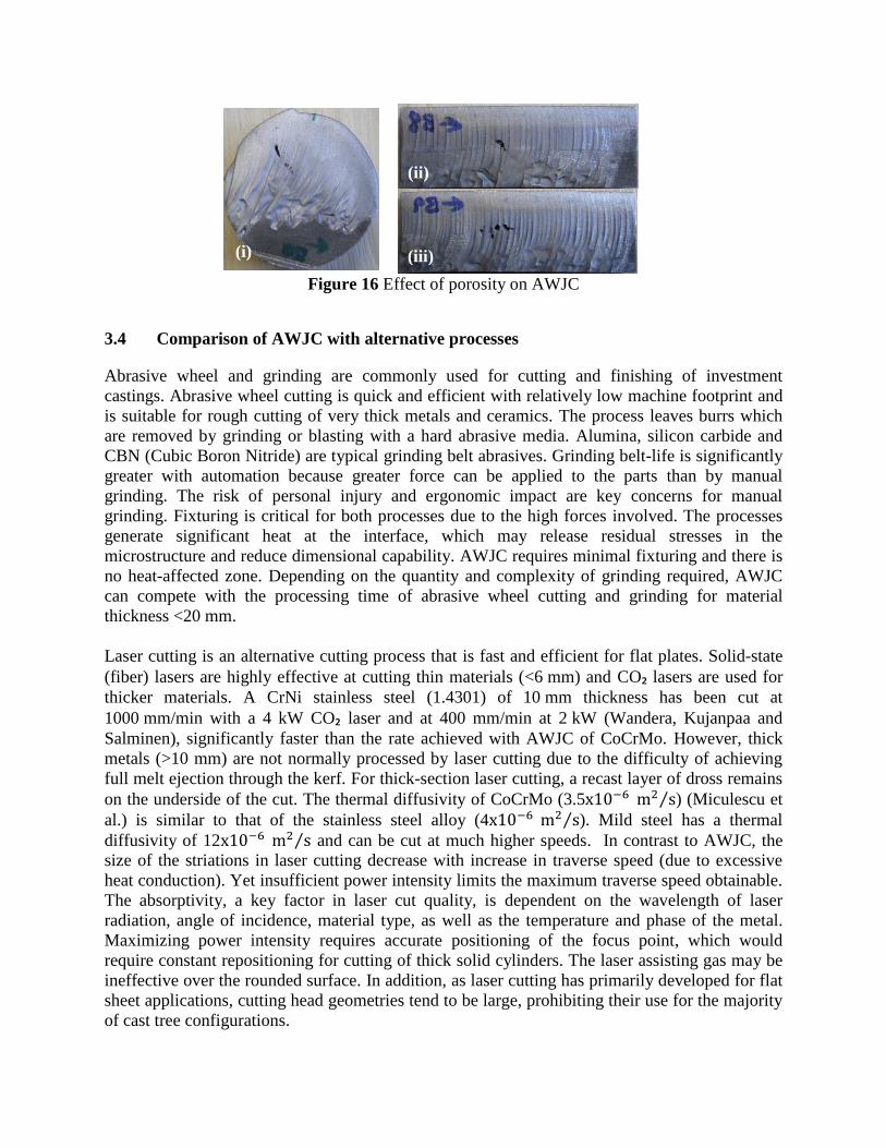
Figure 16 Effect of porosity on AWJC
3.4 Comparison of AWJC with alternative processes
Abrasive wheel and grinding are commonly used for cutting and finishing of investment
castings. Abrasive wheel cutting is quick and efficient with relatively low machine footprint and
is suitable for rough cutting of very thick metals and ceramics. The process leaves burrs which
are removed by grinding or blasting with a hard abrasive media. Alumina, silicon carbide and
CBN (Cubic Boron Nitride) are typical grinding belt abrasives. Grinding belt-life is significantly
greater with automation because greater force can be applied to the parts than by manual
grinding. The risk of personal injury and ergonomic impact are key concerns for manual
grinding. Fixturing is critical for both processes due to the high forces involved. The processes
generate significant heat at the interface, which may release residual stresses in the
microstructure and reduce dimensional capability. AWJC requires minimal fixturing and there is
no heat-affected zone. Depending on the quantity and complexity of grinding required, AWJC
can compete with the processing time of abrasive wheel cutting and grinding for material
thickness <20 mm.
Laser cutting is an alternative cutting process that is fast and efficient for flat plates. Solid-state
(fiber) lasers are highly effective at cutting thin materials (<6 mm) and CO₂ lasers are used for
thicker materials. A CrNi stainless steel (1.4301) of 10 mm thickness has been cut at
1000 mm/min with a 4 kW CO₂ laser and at 400 mm/min at 2 kW (Wandera, Kujanpaa and
Salminen), significantly faster than the rate achieved with AWJC of CoCrMo. However, thick
metals (>10 mm) are not normally processed by laser cutting due to the difficulty of achieving
full melt ejection through the kerf. For thick-section laser cutting, a recast layer of dross remains
on the underside of the cut. The thermal diffusivity of CoCrMo (3.5 ⁄ ) (Miculescu et
al.) is similar to that of the stainless steel alloy (4 ⁄ ). Mild steel has a thermal
diffusivity of 12 ⁄ and can be cut at much higher speeds. In contrast to AWJC, the
size of the striations in laser cutting decrease with increase in traverse speed (due to excessive
heat conduction). Yet insufficient power intensity limits the maximum traverse speed obtainable.
The absorptivity, a key factor in laser cut quality, is dependent on the wavelength of laser
radiation, angle of incidence, material type, as well as the temperature and phase of the metal.
Maximizing power intensity requires accurate positioning of the focus point, which would
require constant repositioning for cutting of thick solid cylinders. The laser assisting gas may be
ineffective over the rounded surface. In addition, as laser cutting has primarily developed for flat
sheet applications, cutting head geometries tend to be large, prohibiting their use for the majority
of cast tree configurations.
(i)
(ii)
(iii)

Electrical discharge machining (EDM) is a highly accurate process whereby an electric current is
used to erode away a conductive material. A charge is passed through a thin wire (approx 1µm
thick) and the conductive material to be cut carries the other part of the charge. The apparatus is
immersed in a dielectric liquid (usually deionised water). When the two charges get close, an
electrical spark jumps the gap and the heat generated melts away tiny particles of the cut
material. The process is suitable for intricate individual parts that require very tight tolerances
(±0.025 mm). Maximum for a 13.6 mm CoCrMo plate was 3.5 mm/min, prohibitively slow
and unsuitable for high-volume cutting applications. As runner system removal often occurs
before complete refractory removal, a robust cutting process should be able to cope with some
remaining ceramic material. EDM is unable to cut non-conductive materials and so could only be
used after thorough refractory removal. Although non-conductive ceramics (zirconia and
alumina) have recently been cut with EDM using an assisting electrode (Hösel, Müller and
Reinecke), this approach would not be feasible for investment castings. One of the advantages of
AWJC is that it can cut through combinations of different materials.
A thorough comparison of the cost of laser and AWJC has been conducted by (Zheng et al.). An
approximate comparison of the three alternative cutting processes is given in table 4. Given that
castings normally have thick, solid round gates and a degree of ceramic normally remains prior
to cutting, laser cutting and EDM are presented with technical challenges and are currently
unsuitable alternatives to the current abrasive wheel cutting and grinding process.
Table 4 Approx. cutting speeds and costs for selected cutting processes
for 13 mm thick
plate
Equipment Cost ($) Running Cost ($/hr)
AWJC 200 mm/min 450,000 70
Laser cutting 400 mm/min 800,000 55
EDM 3.5 mm/min 300,000 2
4. CONCLUSIONS
An empirical formula was generated to estimate for varying for high strength CoCrMo
investment castings. For the same process conditions, flat plates and cylinders achieved an
equivalent cut depth up to the end of the cut. Cylindrical gates are ideal for AWJC as they do not
require reduction towards end of cut to account for waterjet lag effect. The mechanism of
material removal is similar to that of stainless steel and occurs via microchip formation,
ploughing and rubbing.
The technical feasibility and cost considerations of alternative cutting methods for runner system
removal for investment castings were discussed (abrasive wheel and grinding, laser cutting and
EDM). Manual grinding processes carry risk of personal injury and ergonomic concerns. Laser
cutting is unsuitable for cylindrical gates and EDM is prohibitively slow. Both would require
thorough refractory removal prior to cutting. AWJC may be suitable for this process, primarily

depending on the casting tree configuration and gate thickness. Future research will include
refinement and verification of the empirical formula for to include the effect of pressure and
alternative abrasives. Underwater cutting will be investigated as a means to reduce the noise
level.
ACKNOWLEDGEMENTS
The authors would like to acknowledge the EU for the funding support under the Marie Curie
Actions – Industry Academia Partnerships and Pathways, within Framework 7, Grant Agreement
251269, “MEDCAST”, and also for the funding support for FP7 “ConforM-Jet”.
REFERENCES
Arola, D. and Ramulu, M. "Material Removal in Abrasive Waterjet Machining of Metals;
Surface Integrity and Texture." Wear 210 (1997): 50-58. Print.
ASTM. "Astm F75, Standard Specification for Cobalt-28 Chromium-6 Molybdenum Casting
Alloy and Cast Products for Surgical Implants (Uns R30075)." 1998. Print.
Axinte, D. A., et al. "Abrasive Waterjet Cutting of Polycrystalline Diamond: A Preliminary
Investigation." International Journal of Machine Tools and Manufacture 49.10 (2009):
797-803. Print.
Cawley, J., et al. "A Tribological Study of Cobalt Chromium Molybdenum Alloys Used in
Metal-on-Metal Resurfacing Hip Arthroplasty." Wear 255.7–12 (2003): 999-1006. Print.
Gent, M., et al. "Experimental Evaluation of the Physical Properties Required of Abrasives for
Optimizing Waterjet Cutting of Ductile Materials." Wear 284–285.0 (2012): 43-51. Print.
Hlavac, L. M., et al. "Experimental Method for the Investigation of the Abrasive Water Jet
Cutting Quality." Journal of Materials Processing Technology 209.20 (2009): 6190-95.
Print.
Hösel, T., C. Müller, and H. Reinecke. "Spark Erosive Structuring of Electrically Nonconductive
Zirconia with an Assisting Electrode." CIRP Journal of Manufacturing Science and
Technology 4.4 (2011): 357-61. Print.
Miculescu, M., et al. "Thermal Diffusivity of Materials Using Flash Method Applied on Cocr
Alloys." UPB Scientific Bulletin 70.2 (2008): 71-81. Print.
Pon Selvan, M.C. , and N. M. Raju. "An Experimental Investigation on Depth of Cut in
Abrasive Waterjet Cutting of Aluminium." International Journal of Engineering Science
and Technology (IJEST) 3.4 (2011): 2950-54. Print.
Wandera, C., V. Kujanpaa, and A. Salminen. "Laser Power Requirement for Cutting Thick-
Section Steel and Effects of Processing Parameters on Mild Steel Cut Quality."
Proceedings of the Institution of Mechanical Engineers Part B-Journal of Engineering
Manufacture 225.B5 (2011): 651-61. Print.
Zheng, H. Y., et al. "Quality and Cost Comparisons between Laser and Waterjet Cutting."
Journal of Materials Processing Technology 62.4 (1996): 294-98. Print.
NOMENCLATURE
= Coefficient that modifies the limit traverse speed to the value assuring selected quality even
on the worse part of the cutting wall
= Depth of cut (mm)
= Hardness (Vickers)
= Mass flow rate of abrasive particles (g/min)
p = water pressure (MPa)
= surface roughness average (µm)
s = standoff distance (mm)
t = material thickness (mm)
= Traverse speed (mm/min)
θ = Jet impingement angle (˚)
AWJC = Abrasive Water Jet Cutting
DA = Declination Angle, i.e. the angle between the tangent to the striation curve and the
impinging jet axis (˚)
EDM = Electrical Discharge Machining
IDR = Initial Damage Region
SCR = Smooth Cut Region
SEM = Scanning Electron Microscopy
RCR = Rough Cut Region
TC = Through Cut