Embed Size (px)
Citation preview

Abrasive machining of advanced aerospace alloysand compositesKlocke, Fritz; Soo, Sein; Karpuschewski, Bernhard; Webster, John A.; Novovic, Donka; Elfizy,Amr; Axinte, Dragos A.; Tönissen, StefanDOI:10.1016/j.cirp.2015.05.004
License:Creative Commons: Attribution-NonCommercial-ShareAlike (CC BY-NC-SA)
Document VersionPublisher's PDF, also known as Version of record
Citation for published version (Harvard):Klocke, F, Soo, SL, Karpuschewski, B, Webster, JA, Novovic, D, Elfizy, A, Axinte, DA & Tönissen, S 2015,'Abrasive machining of advanced aerospace alloys and composites' CIRP Annals - Manufacturing Technology,vol 64, no. 2, pp. 581-604. DOI: 10.1016/j.cirp.2015.05.004
Link to publication on Research at Birmingham portal
General rightsUnless a licence is specified above, all rights (including copyright and moral rights) in this document are retained by the authors and/or thecopyright holders. The express permission of the copyright holder must be obtained for any use of this material other than for purposespermitted by law.
•Users may freely distribute the URL that is used to identify this publication.•Users may download and/or print one copy of the publication from the University of Birmingham research portal for the purpose of privatestudy or non-commercial research.•User may use extracts from the document in line with the concept of ‘fair dealing’ under the Copyright, Designs and Patents Act 1988 (?)•Users may not further distribute the material nor use it for the purposes of commercial gain.
Where a licence is displayed above, please note the terms and conditions of the licence govern your use of this document.
When citing, please reference the published version.
Take down policyWhile the University of Birmingham exercises care and attention in making items available there are rare occasions when an item has beenuploaded in error or has been deemed to be commercially or otherwise sensitive.
If you believe that this is the case for this document, please contact [email protected] providing details and we will remove access tothe work immediately and investigate.
Download date: 02. Jul. 2018

aryineing
faceith
micsiveials,tooll asthesternceote
areface
the
CIRP Annals - Manufacturing Technology 64 (2015) 581–604
that
and.
gine
r are
ms,
arch
cent
IRP.
Abrasive machining of advanced aerospace alloys and composites
Fritz Klocke (1)a, Sein Leung Soo (2)b,*, Bernhard Karpuschewski (1)c, John A. Webster (1)d,Donka Novovic e, Amr Elfizy f, Dragos A. Axinte (1)g, Stefan Tonissen a
a Laboratory for Machine Tools and Production Engineering, WZL, RWTH Aachen University, Aachen, Germanyb Machining Research Group, School of Mechanical Engineering, University of Birmingham, Birmingham, United Kingdomc Institute of Manufacturing Technology and Quality Management, Otto-von-Guericke-University of Magdeburg, Magdeburg, Germanyd Cool-Grind Technologies, Ashford, CT, United Statese Rolls-Royce plc, Derby, United Kingdomf Pratt and Whitney Canada, Longueuil, QC, Canadag Rolls-Royce University Technology Centre (UTC), Faculty of Engineering, University of Nottingham, Nottingham, United Kingdom
1. Introduction
The worldwide market for civil aircraft is rising in line withincreasing global population and affluence. Growth in newairplane deliveries is expected to be at an average of 3.6% perannum up to 2030 [114]. This naturally translates to a greaterdemand for gas turbine engines, which places significant strains oncurrent as well as future supply chain and production capacity.
Commercial pressures for continuous improvement in aeroen-gine performance and fuel efficiency have driven the development ofmaterials with increasing temperature limits at affordable cost[65]. This is evident from the evolution of materials composition inengines, with the trend moving towards alloys with highertemperature capability (from steels to nickel and titanium alloys)and materials with lower density (aluminium to carbon fibrecomposites). Although not fully mature, ceramic and metal matrixcomposites (CMC and MMC) are showing evidence of replacing someof the high temperature alloys that dominated engines towards theend of the 20th century. The constantly changing state of aeroenginematerials technology is another factor that will considerably stretchthe limits/capability of established manufacturing processes andtherefore further emphasises the critical need to develop more
turbomachinery parts [123], grinding is still one of the primoperations in the finish machining of critical gas turbine engcomponents. This is due to the strict requirement for achievtight dimensional tolerances of <10 mm and superior surfinish with roughness in the order of <0.5 mm Ra together wacceptable workpiece quality/integrity.
The keynote will discuss the latest developments in acaderesearch together with current state-of-the-art relating to abramachinability of key aerospace alloys and composite materfluid delivery and wheel preparation strategies, machine
technologies and innovative process configurations, as welexample case studies and perspectives from practitioners in
aeroengine manufacturing sector. The paper complements a sikeynote to be presented in STC-C relating to the ‘High performacutting of advanced aerospace materials’ as well as the keyndelivered last year (2014) in STC-E [123].
2. Workpiece surface/sub-surface integrity requirements
Aeroengine discs are categorised as critical components andtherefore subject to highly stringent dimensional accuracy, surintegrity and fatigue requirements. It is well documented that
A R T I C L E I N F O
Keywords:
Abrasion
Grinding
Material removal
A B S T R A C T
The aerospace industry has experienced significant growth over the past decade and it is estimated
nearly 30,000 new commercial passenger aircraft will be required by 2030 to meet rising global dem
Abrasive machining is a key material removal process utilised in the production of aeroen
components. Current industrial practice and perspectives relating to grinding in the aerospace secto
presented including general workpiece surface integrity standards/requirements, fluid delivery syste
wheel preparation options and machine tool designs/configurations. Corresponding academic rese
on the machinability of aerospace alloys and composites are critically reviewed together with re
developments involving novel/innovative grinding processes.
� 2015 C
Contents lists available at ScienceDirect
CIRP Annals - Manufacturing Technology
journal homepage: http: / /ees.elsevier.com/cirp/default .asp
s isfaceons
advanced and robust production techniques.Despite the rapid development and increasing acceptance of
non-conventional machining processes for the manufacture of
on50s.the
gies* Corresponding author. Tel.: +44 1214144196.
E-mail address: [email protected] (S.L. Soo (2)).
http://dx.doi.org/10.1016/j.cirp.2015.05.004
0007-8506/� 2015 CIRP.
functional performance of parts subject to machining processestrongly affected by the resulting material surface/subsurintegrity conditions [111]. Publications detailing investigatirelating to the influence of material removal processes
workpiece residual stresses initially appeared in the 19However, Field and Kahles [66] were the first to define
concept of surface integrity and propose associated methodolo

for a[67,
Waccecomdiscmetgrinanomforewouresid
3. A
3.1.
Sengiand
tougcracwer[245hardHY1[245AerMwhisupe
X100
streto
subsas ctemvs =
[245to �whiof uaffecto thcomhighextegrinwhe10 minvosimifeedmacgrinspinutiliof w
3.2.
Ncurrthe ccan
vaneprocstruthro�25
F. Klocke (1) et al. / CIRP Annals - Manufacturing Technology 64 (2015) 581–604582
ssessment, with particular application to machining processes68].
hile specific standards of workpiece surface integrity andptance criteria for aerospace components exist, they aremercially sensitive and closely guarded, which precludes fulllosure in the public domain. Nevertheless, surface integrity/allurgical assessment of the workpiece condition followingding is typically undertaken to confirm the absence of various
alies including cracks, amorphous/recast layers, re-deposited/ign material, contamination and work hardening, none of whichld be acceptable. In addition, the analysis can also encompassual stress measurement and cyclic life assessment.
brasive machinability of aerospace materials
Stainless steels
tainless steel is typically utilised for the manufacture of jetne shafts and aircraft structural components such as fastenerslanding gears requiring elevated strength, high fracture
hness and exceptional ability to withstand stress corrosionking. The first stainless steels employed in the aviation industrye the low-alloy martensitic steels, AISI 4130 and AISI 4340]. In 1978, Little and Machmeier [143] patented the secondaryening ultra-high strength steel AF1410, which was based on80 but with increased toughness and corrosion resistance]. This was further improved through the introduction ofet 100 in the 1990s by Carpenter Technology Corporation,
ch is currently widely utilised in the aviation industry due to itsrior fracture toughness and corrosion stress resistance [245].u et al. [242] studied the abrasive machining of AerMetusing white Al2O3 vitrified grinding wheels. Tensile residual
sses were detected in the top surface layer, which crossed overthe compressive regime when moving deeper into theurface zones. The influence of single and white Al2O3 as wellubic boron nitride (CBN) wheels on resulting force and
perature when surface grinding AerMet 100 (vw = 8–14 m/min,20–30 m/s, ap = 5–25 mm) was assessed by Yao et al.]. Both grinding force (up to �290 N) and temperature (up735 8C) were highest when utilising the single Al2O3 wheel,
le tests with CBN resulted in reduced forces and temperaturesp to �75% and 100% respectively, as well as smaller heatted zones. The superior performance was primarily attributede higher thermal conductivity of the CBN grain (133 W/m K)
pared to Al2O3 (35 W/m K) abrasive. Subsequent trials alsolighted that compressive residual stresses up to �1000 MPanding to a depth of �30 mm was obtained when surfaceding AerMet 100 using CBN wheels at a workpiece feed (vw),el speed (vs) and depth of cut (ap) of 18 m/min, 14 m/s andm respectively [246]. In contrast, the majority of trialslving white Al2O3 wheels exhibited tensile residual stresseslar to that reported by Xu et al. [242]. The feasibility for creep grinding of AISI 420 stainless steel using a vertical high-speedhining centre was demonstrated by Dewes et al. [51]. Despiteding forces of up to 650 N, no problems occurred with regard todle power or vibration/instability. The alumina-based wheelsed achieved a maximum G-ratio of 41, with no apparent signsorkpiece burn.
equiaxed parts. This is because the grain boundaries of DS bladesare aligned along the principal stress direction parallel to the airfoillength [39]. A further 25 8C boost in allowable blade operatingtemperature can be achieved by single crystal (SX) airfoil castings,which do not contain any grain boundaries [189]. While modernhigh-pressure turbine airfoils are either DS or SX cast, the rearsections/cooler stages of the turbines are manufactured fromequiax grained alloys. Structural components such as enginecasings are similarly produced via investment casting whilewrought processes involving cast ingots or consolidated superalloypowder preforms are applied to fabricate turbine discs [180].
Grinding is a key process for the manufacture of blades and vanesas economic machining of cast nickel-based superalloys usingdefined cutting edge operations is difficult. Depending on partdesign, up to 12 distinct abrasive cutting operations are required tomachine a blade, see Fig. 1 [228], including face, plunge, profile andarc grinding. Arguably, the most important feature on a blade is the‘fir tree’ shaped profile at the root that locates it into the rotor [86].
The process of turbine blade grinding in the aeroengineindustry has seen significant evolution over the past 60 years.Use of creep feed grinding (CFG) at low table speeds and largedepths of cut with soft and porous Al2O3 wheels at low cuttingspeeds (15–30 m/s) was predominant in the 1950s. Intermittentdressing using formed diamond rolls was the principal method forwheel preparation. The advent of continuous dress creep feed(CDCF) grinding in the 1980s allowed for much higher materialremoval rates, with roll dresser infeed levels of between 0.5 and2.0 mm/rev preserving wheel profiles and keeping Al2O3 gritssharp. An alternative configuration when operating at wheelspeeds of up to 80 m/s is high-speed continuous dress (HSCD)creep feed grinding. Infeed levels in HSCD are a factor of 5 to10 larger compared to CDCF [166]. Unfortunately, the radicallyfaster wear rate of grinding wheels and dressers when using HSCDhas thus far prevented any widespread industrial application.
Fig. 2 shows a metallographic cross-section of an IN738LCworkpiece following creep feed grinding using an intermittentlydressed Al2O3 wheel. A 5 mm thick white etch layer is clearly
Fig. 1. Ground features on a high-pressure turbine blade [228].
Fig. 2. Machined subsurface of IN738LC following CFG [173].
Nickel based superalloys
ickel based superalloys constitute 40–50% of engine weight inent commercial aircraft and are deployed particularly withinombustor and turbine sections where operating temperaturesexceed 1250 8C [189,201]. Turbine blades and nozzle guides (NGV) are formed through complex investment castingesses capable of precisely controlling the grain boundarycture. Components that contain columnar grains fabricatedugh directionally solidified (DS) casting generally have a 8C higher operational temperature limit compared to

ssesredyerlloyion,tedTf)
(1)
een theeakthe
thatwasUn-nothe-
era-ieceuresedtheurn417hip
F. Klocke (1) et al. / CIRP Annals - Manufacturing Technology 64 (2015) 581–604 583
observed on the machined surface and is devoid of any of thecoarse cuboidal g0 particles present within the bulk material.
This amorphous zone most likely formed due to the elevatedtemperatures generated during the grinding process. Whengrinding with intermittently dressed wheels, the white etch layerwas found to be minimal for a dress overlap rate (Ud) of 3.8. In CDCFgrinding, the depth of the white etch layer was shown to decreasesteadily with increasing dressing infeed velocity [173].
Osterle et al. [174] evaluated the influence of four distinctoperating conditions on workpiece residual stress when creep feedgrinding cast IN738LC; see Fig. 3. Grinding dry resulted in largetensile residual stresses of up to �1800 MPa both parallel andorthogonal to the grinding direction; see Fig. 3(a). The damagedsurface/subsurface region was also characterised by cracking whilethickness of the white etch layer was greatest. The residual stressdepth profile after grinding using an Al2O3 (corundum) wheel withintermittent dressing (single crystal diamond tool) is detailed inFig. 3(b). Surface residual stress was tensile in nature and peaked atabout 5 mm into the subsurface, which corresponds to thethickness of the nanocrystalline white etch layer detailed inFig. 2 [173]. The residual stresses crossed over into the compressiveregion at �15 mm beneath the machined surface, with a maximumof approximately �400 MPa observed at a depth of 50 mm. Thiswas counterbalanced by equivalent tensile residual stresses at adepth of 100–120 mm below the machined surface.
Operating with continuous dressing reduced the magnitude anddepth of tensile residual stresses near the workpiece surface in
depth of 90 mm [174]. The relatively low tensile residual strewere attributed to the high thermal conductivity of CBN compato Al2O3 [173]. Osterle et al. [174] also suggested that white laformation occurred as the melting temperature of the IN738LC awas exceeded during grinding. In order to verify this assumptmaximum temperatures in the grinding zone (Tmax) were calculaas a function of stationary (DTs) and flash temperatures (Daccording to the relationship shown in the following equation:
Tmax ¼ 300 þ DTs þ DT f
Stationary temperatures DTs relates to the difference betwthe overall heat input into the workpiece and heat transfer tocoolant, whereas flash temperatures DTf describe the ptemperature resulting from cutting edges passing over
workpiece material. The temperature calculations indicated
the melting temperature (1427 8C) of the workpiece material
indeed exceeded whenever white layers were formed [173].
fortunately, relevant experimental temperature data was
available to validate the predicted values and associated hypotsis regarding white etch layer formation. Experimental tempture measurements obtained via grindable foil/workpthermocouple-based techniques were reported in the literatwhen surface grinding K417 [240] and DZ4 [40] nickel basuperalloys using conventional abrasives. In contrast to
calculations by Osterle et al. [174], initial signs of workpiece bwere evident at temperatures of 990 8C and 950 8C for the Kand DZ4 workpieces respectively [40,238,240]. The relations
Fig. 3. Influence of creep feed grinding conditions on residual stress depth profiles of IN738LC [174].
ter-
Table 1Relationship between surface colour and maximum temperature [240].
Material K417 Maximum temperature at contact zone, u (8C)
95 990 1215 1440 1600
Colour Normal Beige Brown Puce Hyacinthine
comparison to intermittent dressing, as highlighted in Fig. 3(b) and(c) respectively [174]. A possible explanation for the lower tensileresidual stresses is the significantly smaller specific force whencreep feed grinding with continuous dressing [204]. Compressiveresidual stresses was extended to a depth of �60 mm with amaximum of ��800 MPa recorded 10 mm below the machinedsurface and orthogonal to the grinding direction [174]. The trend inresidual stress variation following CFG using a CBN wheel wassimilar to that when grinding with a continuously dressedconventional wheel. Surface residual stresses were marginallytensile with compressive subsurface residual stresses extending to a
between surface colour and maximum temperatures as demined by Xu et al. [240] for K417 are outlined in Table 1.

Unormusedgenethe
ing
incrsuffilayeplasthe
geneW
abrainclumairequwatoil flelecbaseadheConwithexpeelecand
CBNtemsupesom
AvaricomtermwhepowelevThisas tcons
Uintegrinrepovitrimagwasincrbon
Sgrin(macreewheparagenewheIchidwheconvexhicorrspecSunafor
Mor(5–4inteusin
F. Klocke (1) et al. / CIRP Annals - Manufacturing Technology 64 (2015) 581–604584
pon initiation of workpiece burn, the ratio of tangential andal forces (Ft/Fn) dropped significantly [238], which can be
as an indicator for process monitoring [39,40]. Grinding burnrally leads to subsurface softening (lower microhardness) of
workpiece together with formation of transfer films compris-Ni2O3, Cr2O3, Al2O3 and TiO2 on the machined surface. Witheasing cutting temperatures, the workpiece material becomesciently ductile to weld onto the grinding wheel. The adheredr is then typically re-deposited onto the workpiece surface astically deformed/smeared material in successive revolutions ofgrinding wheel. Consequently, workpiece surface roughnessrally increases at elevated temperatures [238].hen grinding nickel-based superalloys using CBN super-
sives, three different bond systems are normally utilised,ding single layer electroplated, vitrified or brazed wheels. The
n advantage of electroplated wheels is that dressing is notired [86]. Gift et al. [72] compared the performance of three
er-based coolants (emulsion and synthetics) against a straightuid when creep feed grinding a nickel-based superalloy usingtroplated CBN wheels. All of the wheels tested with water-d fluids exhibited rapid failure due to severe clogging fromred chips leading to a drastic increase in cutting forces.
versely, no sign of wheel loading was evident when grinding oil as exemplified by stable force progression over theriment duration. Similarly, Liu et al. [144] observed that
troplated CBN wheels performed poorly when grinding CMSX4Inconel 718 nickel based superalloys with emulsion, as the
grits were prone to react with water especially at elevatedperatures. While electroplated diamond wheels demonstratedrior G-ratios over equivalent CBN wheels, the benefits wereewhat negated by the higher cost of diamond abrasives [145].
further disadvantage of electroplated CBN wheels is that largeations in wheel life and transient grinding behaviour [84] aremonly observed, which imposes considerable challenges ins of effective wheel utilisation and process control. The end of
el life is generally denoted by a sharp increase in grindinger due to grain fracture, pullout and attrition, which leads toated grinding temperatures and risk of white layer formation. can to a degree be mitigated using process control tools suchhe model derived by Guo et al. [77] to predict the powerumption of new and worn wheels.nlike electroplated wheels, vitrified CBN wheels can be
rmittently dressed, which generally leads to more consistentding behaviour. Additionally, water based coolants have beenrted to provide acceptable performance when grinding withfied CBN wheels [85] although wheel life remains an order ofnitude higher when employing straight oil fluid. Wheel life
further enhanced when employing CBN grain coatings, whicheased the adhesion strength between the grains and vitreousd system [223].hi et al. [195,196] identified optimal dressing conditions fording using vitrified wheels. It was found that low depths of cutximum of 0.5 mm) and high work feeds were preferred overp feed conditions in order to increase material removal ratesn utilising vitrified bonded wheels. In addition, grindingmeters for roughing had to be adjusted accordingly to preventration of excessive cutting temperatures for newly dressedels and to suppress chatter when operating with worn wheels.a et al. [103] evaluated the grinding behaviour of Nimonic 80A
tensile (�700 as opposed to 1200 MPa), workpiece roughnessdecreased (to 0.284 from 0.896 mm Ra) with no indication ofmaterial cracking and minimal subsurface microstructural alter-ation (�3 mm) when operating at the lowest depth of cut of 5 mm,see Fig. 4(a). However, when depth of cut was increased to 40 mm,cracking was evident on the machined surface perpendicular to thegrinding direction together with material overlap/smearing asdetailed in Fig. 4(b).
3.3. Titanium alloys
Titanium alloys account for approximately 33% of the weight incivil aircraft engines due to their high specific strength, moderateelevated temperature performance (�350 8C) and good corrosionresistance [27]. The most widely used titanium alloy is the alpha-beta Ti–6Al–4V (Ti-64), which is employed in various fastenercomponents as well as for airfoils, discs and casings in the fan andlow pressure compressor [56,87,202]. Other common alloysinclude Ti–6Al–2Sn–4Zr–2Mo (Ti-6242) and Ti–6Al–2Sn–4Zr–6Mo (Ti-6246), which possess higher strength as well astemperature resistance (up to �400–500 8C) and are thereforeapplied in rear low pressure and front high pressure compressorparts [56,202]. However, conventional titanium alloys canpotentially ignite and burn when subject to temperaturessignificantly above 350 8C [227], which prevents their use in latterstages of the high-pressure compressor where conditions aregenerally beyond the ‘fire line’ [167]. In recent years, alloys withincreased operating temperature limits such as burn resistanttitanium (BuRTi) Ti–25V–15Cr–2Al–0.2C wt% (at least 500 8C) andgamma titanium aluminides (700–750 8C depending on composi-tion) have been proposed as potential replacements for heaviernickel based superalloys in the hotter regions of the engine.Following several decades of research together with limited use inmilitary and land-based gas turbines, gamma titanium aluminide(g-TiAl) turbine blades have recently been implemented withinvarious low-pressure stages of commercial aeroengines [87].
The thermal and mechanical properties of titanium alloyshowever present serious difficulties for abrasive machining. Inparticular, the thermal diffusivity of Ti-based alloys is considerablylower compared to other common engineering materials/alloys;see Table 2 [87,130,194]. For similar energy input levels,temperatures are expected to be 3–4 times greater when grindingtitanium as opposed to nickel alloys [87]. Furthermore, titaniumalloys have a strong affinity for compounds containing nitrogen,oxygen, carbon and halogens, which trigger chemical reactions atelevated temperatures [130].
Fig. 4. SEM micrographs of ground GH4169 nickel based superalloy surfaces at
depths of cut of (a) 5 and (b) 40 mm [247].
Table 2Heat diffusivity of various engineering materials and abrasives [194].
Material Heat diffusivity (kcr)1/2 [103 J/(m2 s1/2 K)]
Carbon steel 15.7
Stainless steel 9.7
Nickel based superalloy 18.9
Aluminium alloy 23.0
Ti-6Al-4V 5.0
g-TiAl 4.0
Diamond 60
CBN 48
Al2O3 12.5
SiC 8.7
n using vitrified bonded ultrafine-crystalline CBN (CBN-U) andentional monocrystalline CBN (CBN-B) wheels. The formerbited a 10-fold increase in wheel G-ratio together withespondingly lower grinding force components (Fn and Ft) andific energy (ec) compared to the CBN-B product. Likewise,rto and Ichida [207] concluded that CBN-U was better suited
grinding applications requiring high dimensional accuracy.e recently, Zeng et al. [247] showed that varying depths of cut0 mm) had a significant influence on workpiece surface
grity when surface grinding GH4169 nickel based superalloyg a Al2O3 wheel. Although surface residual stresses remained

ead,earBNces
undyerandess,rce
theeptnceingvedeelsller
cificeels
zedno-hergergritindingificbly
tive
cup bemi-rnaltity
led
.
F. Klocke (1) et al. / CIRP Annals - Manufacturing Technology 64 (2015) 581–604 585
Much of the fundamental work on abrasive machining of Ti-64was initiated in the 1950s. Several researchers demonstrated thatTi could be successfully ground using conventional aluminiumoxide (Al2O3) and silicon carbide (SiC) abrasives when operatingwith inorganic water soluble coolants and relatively low wheelspeeds of the order of 10 m/s [87,193,209,243]. In belt grindingexperiments, Cadwell et al. [35] showed that SiC was approxi-mately 10 times more effective than Al2O3 under an organic fluidenvironment. This was attributed to the ability of SiC abrasives toform shaper cutting edges in comparison to Al2O3 grains, therebypromoting lower cutting forces at comparable material removalrates [74,89]. Therefore, Olofson et al. [170] recommendedsignificantly lower cutting speeds when grinding Ti with Al2O3
wheels in order to mitigate the risk of workpiece thermal damage.Turley [220] found that Ti workpiece material was more
inclined to adhere onto Al2O3 as opposed to SiC wheels. Whengrinding Ti-64 with SiC abrasives at temperatures between800 and 1140 8C, SiC can react with atmospheric oxygen (O2) toproduce SiO2 and C according to the following equation:
SiC þ O2ðatmosphereÞ ! SiO2þ C (2)
Subsequently, the loose carbon reacts with the titaniumelement to form TiC as detailed in the following equation:
Ti þ C ! TiC (3)
For workpiece temperatures above 500 8C, oxidation of thetitanium can also occur; see the following equation:
Ti þ O2ðatmosphereÞ ! TiO2 (4)
Tang et al. [208] identified the presence of TiC and TiO2 withinthe burnt surface layers of Ti-64 following surface grinding. Theinterfacial diffusion due to the chemical reactions results in strongbonds between the workpiece and SiC grains [79,239,241]. Addi-tionally, the ductility of Ti-64 encourages material adhesion ontothe grain surfaces. Subsequent growth of the adhered layer leads toeventual detachment (due to increasing loading) from the grits,which is re-deposited onto the workpiece surface as a film ofsmeared ‘coating’ [239]. Under high temperature conditions(�1000 8C), the detached layer of material can also result inscarring of the machined surface, as well as corresponding wear ofthe abrasives [239,241].
In the early 1980s, Kumagai et al. [129] demonstrated that thegrinding efficiency of titanium can be enhanced by supplyingcutting fluid at elevated pressure (2 MPa) in combination with useof superabrasive diamond instead of conventional SiC wheels.Results from a comparative evaluation of various resin-bondedsuperabrasives (diamond and CBN) against vitrified SiC wheelsconfirmed the superior performance of diamond for grinding Ti-64,with G-ratios of up to 150 and low specific grinding energies of<30 J/mm3; see Fig. 5 [130]. Furthermore, wheel G-ratio andspecific energy (ec) were also found to be influenced by themechanical properties of the superabrasives, with the mediumtoughness diamond grits (CSG-II and MBG-II) showing enhancedgrinding characteristics over the low toughness RVG-W diamondabrasive; see Fig. 5 [130].
Kumar [130] explained that the poor performance of CBNrelative to diamond was due to the greater tendency of Ti-64 toreact chemically with the former. The principal damage mode ofthe CBN grains was attrition leading to the formation of large wear
low to trigger the chemical reactions detailed in Eqs. (5)–(7). Instthey argued that chemical reactivity was not the dominant wmechanism as adhered material was significantly lower in Ccompared to SiC wheels. Consequently, there were fewer instanof re-deposited material evident on the workpiece surface growith a CBN wheel [241]. Severe adhesion of Ti-chips on single labrazed CBN wheels was also observed when grinding under dry
cryogenic assisted (liquid nitrogen) conditions [213]. Neverthelsubsequent work revealed that both tangential and normal focomponents were typically �25–40% lower when employingCBN over brazed diamond (natural and synthetic) wheels, excwhen operating dry [214]. Li et al. [137] compared the performaof brazed, vitrified and electroplated CBN wheels when grindTi-64. Highest specific material removal rate (Q0w) was achieusing the brazed wheels. Furthermore, monolayer CBN whbrazed with an amalgamated Ag–Cu–Ti + 0.5 wt% lanthanum fiwas shown to provide reduced tangential forces and lower spegrinding energy compared to straight monolayer CBN whbrazed with a pure Ag–Cu–Ti filler [244].
Ding et al. [55] investigated the grinding behaviour of brapolycrystalline cubic boron nitride (PCBN) compared to mocrystalline CBN abrasives. The former demonstrated higmaterial removal rates and lower wheel wear (up to 30% lontool life), as the latter suffered from severe microcrystalline
fracture. Shi and Attia [197] showed that it was feasible to grtitanium alloys with electroplated CBN wheels when applyhigh-pressure wheel cleaning. Under such conditions, the specenergy in creep feed grinding of titanium alloy was consideralower than that of nickel superalloy grinding, due to the effecelimination of wheel loading.
The use of an innovative self-inhaling internal cooling CBN
wheel enabled surface temperatures when grinding Ti-64 toreduced by 30% and 50% when utilising oil and water-based sesynthetic fluid respectively, as opposed to conventional extecooling [139]. Similarly, the application of minimum quanlubrication (MQL) with vegetable and synthetic ester based oils
Fig. 5. Grinding characteristics of superabrasives compared to SiC [130]
henface
ining
wetwasuid
4 isde-
tion
flats, which is indicative of a chemically assisted wear mechanism[130]. The possible chemical reactions that can occur duringgrinding of Ti-64 with CBN are outlined in the following equations:
2BN þ 3=2O2 ! B2O3þ N2 (5)
N2þ 2Ti ! 2TiN (6)
B2O3þ TiO ! TiB2þ 2O2 (7)
However, Xu et al. [241] showed that temperatures whengrinding Ti-64 with CBN were approximately 1000 8C and thus too
to a two-fold decrease in forces compared to flood cooling wgrinding Ti-64, albeit at the cost of increased workpiece surroughness [187]. Conversely, only a marginal reductiontangential forces (�15%) was recorded when surface grindTi-64 under cryogenic cooling environment in contrast to
soluble oil conditions [191]. However, cryogenic cooling
rendered ineffective at higher wheel speeds (25 m/s) as the liqN2 mist failed to penetrate the grit-chip interface.
Another solution reported to improve the grindability of Ti-6the use of wheels treated with solid lubricants such as molybnum disulphide (MoS2) and graphite [208,224]. Here, fric

betwcorrMorablamicrcallywhemicrthe
TasseoperatedagaicreeutiliincrporobothsurfFig.
diamcond
Hworin thcratet awhe1.25BuRensualth
Iof lotougflat
ductturnavairela[15,and
watrepoenersuch
Fi
F. Klocke (1) et al. / CIRP Annals - Manufacturing Technology 64 (2015) 581–604586
een the workpiece and abrasives is minimised resulting in aesponding reduction in grinding force and specific energy.e recently, Butler-Smith et al. [33,34] developed a novel lasertion processing technology in order to produce diamondo-grinding tools with ordered cutting edges. The geometri-
defined superabrasive grits exhibited superior performancen grinding Ti-64 over traditional electroplated diamondo-grinding tools, due to the improvement in chip flow over
grain surface and considerable decrease in wheel loading.he grinding of BuRTi (Ti–25V–15Cr–2Al–0.2C wt%) has beenssed by several researchers using different abrasives andating conditions [91,92,167,202]. Novovic et al. [167] evalu-
the performance of conventional and porous SiC wheelsnst a vitrified bonded diamond superabrasive wheel whenp feed grinding BuRTi. Severe surface burn was apparent whensing the conventional SiC wheel, while high wear rates andeased workpiece surface roughness were characteristic of theus SiC product, see Fig. 6(a). The diamond wheel outperformed SiC wheels and exhibited minimal wheel wear, reduced
ace damage and comparably lower workpiece roughness, see6(b). The considerable improvement when employing theond wheel was attributed primarily to its higher thermaluctivity of up to 2000 W/m K.owever, the presence of brittle TiC particles within the
kpiece microstructure meant that surface/subsurface damagee form of material pullout, smearing, fractured carbides and
er formation remained prevalent, see Fig. 7. Later work by Hoodl. [91,92] revealed that low operating parameters involving ael speed of 15 m/s, feed rate of 150 mm/min and depth of cut of mm were required to obtain crack free surfaces when CFGTi with SiC wheels. Equivalent conditions were necessary tore burn free surfaces using vitrified diamond wheels [202],
ough the corresponding G-ratio was poor (between 2 and 6).ntermetallic g-TiAl alloys are characterised by a combinationw room temperature ductility (typically �2%), low fracturehness (�20 M Pa m1/2), steep crack growth rates and relatively
than BuRTi when using SiC wheels (10-fold increase in wheel G-ratio, 10% lower maximum power, 25% lower specific energy, 28%lower tangential forces and 15% lower average workpiece surfaceroughness) [91,92]. Simao et al. [198] compared the plungegrinding of an orthorhombic TiAl alloy (Ti–23Al–25Nb–0.35Si at%)against Ti-64 and g-TiAl (Ti–48Al–2Mn–2Nb) using a conventionalSiC wheel. Wheel G-ratio when machining the orthorhombic TiAlmaterial was marginally higher compared to Ti-64, but signifi-cantly lower with respect to g-TiAl, see Fig. 8 [19,198].
The performance and selection of different abrasives forgrinding g-TiAl has been discussed in several publications[7,74,90,92,120,160,185,206]. Groning [74] carried out extensivesingle grain planar scratch tests and associated grinding experi-ments to assess the suitability of Al2O3, green SiC, CBN anddiamond abrasives for machining g-TiAl. In terms of conventionalabrasives, SiC generally formed sharper cutting edges compared toAl2O3, which was prone to wear flat formation. This led to lowerthermal and mechanical loads when grinding with SiC. As forsuperabrasives, the CBN grains displayed greater chemical andmechanical wear rates coupled with considerably larger specificforces (F0n) in comparison to diamond. Additionally, surface crackstogether with workpiece tempering/burn were visible even whenoperating at parameters corresponding to low specific materialremoval rates (Q0w = 5 mm3/mm s) when using CBN wheels[74]. This corroborated the results of Hood et al. [94], whoobserved extensive burning and fracture in all trials involving CBN,whereas no visible macro cracking was detected on surfacesground using diamond wheels, see Fig. 9. Stone and Kurfess [206]also reported that workpiece surface damage was most severewhen grinding g-TiAl with CBN. This can be partly explained fromthe higher grinding specific energy of 400 J/mm3 measured forCBN, compared to only 40 J/mm3 for diamond abrasives as outlinedby Razavi et al. [185].
Hood et al. [92] suggested that the preferred wheel speed forCFG of g-TiAl using SiC abrasives is 15 m/s. The higher thermal
g. 6. Surface of BuRTi following CFG with (a) SiC and (b) diamond [167].
Fig. 7. SEM micrographs of BuRTi surface/subsurface damage [167].
Fig. 8. Wheel G-ratio curves when grinding orthorhombic TiAl, g-TiAl and Ti-64
[19,198].
Fig. 9. Micrographs of g-TiAl surfaces produced following grinding using (a)
diamond and (b) CBN wheels [94].
fatigue response [4,18,134,152,192,222]. The low materialility however presents less of a problem for grinding thaning [14]. There is a considerable amount of research literaturelable on the abrasive cutting of g-TiAl, which include studiesting to centreless grinding [112], creep feed grinding93,250], reciprocating surface grinding [16,17,21,162–164]speed-stroke grinding [73,120,121,249], as well as abrasive
erjet machining outlined by Kong and Axinte [125]. It has beenrted that g-TiAl is easier to grind than Ti-64, with specificgies typically 2–4 times lower [14,19]. Equally, g-TiAl alloys
as Ti–45Al–8Nb–0.2C wt% also exhibit better grindability
conductivity of diamond (�2000 W/m K) and CBN (�1300 W/m K)in comparison to SiC grains (�40 W/m K) allowed increments incutting speed up to 50 m/s before onset of surface burn [94,127]. Atypical surface defect that occurs after grinding of g-TiAl is bendingof the lamellae due to mechanical loading, see example in Fig. 10[248]. Zeppenfeld [248] showed using single grain scratch tests,that it was possible for cracks to initiate from regions of bentlamellae and therefore workpiece microstructural deformationshould be minimised as much as possible.
Bentley et al. [16] investigated the influence of single pointdiamond dresser infeed levels (0.1 and 0.3 mm/rev) on cutting

ofmalt at(Fn/eedred/sit-
(C, (C,
nce,resver
anditedSiCnlyuchgedinesand
aveingibitrityoicemicear
orsultzar-ondear
andatesg atentll ashering
h toonsenttheure
onun-
.
F. Klocke (1) et al. / CIRP Annals - Manufacturing Technology 64 (2015) 581–604 587
forces and workpiece surface integrity when surface grinding g-TiAl with SiC wheels. Increasing infeed had no appreciableinfluence on the tangential force and workpiece microhardness,but resulted in lower normal forces and increased surfaceroughness (due to sharper grits). Similar trends were obtainedin trials involving continuous dressing [20].
3.4. Composites
A range of state-of-the-art composite materials encompassingmetal matrix composites (MMC), ceramic matrix composites(CMC) and polymer matrix composites (PMC) are increasinglybeing utilised in aerospace applications [205]. Within the family ofMMCs, particulate metal matrix composites (PMMC) and fibre-reinforced MMCs are the most widely researched [226]. The twomost common metallic elements used as the matrix phase inMMCs are aluminium (Al) and titanium (Ti) [95]. Aluminium basedMMCs that display the greatest potential for aerospace applica-tions are those reinforced with fine SiC particles (<12 mm), whichprovide a good balance of high specific strength, ductility andtoughness. As such, they are viable alternatives to Ti-64 forgingsfor manufacturing static and dynamic vanes, offering a possibleweight reduction of up to �35%. However, the strength and fatigueproperties of Al MMC’s are currently inadequate for bladecomponents [95].
In general, SiC particulate reinforced Al matrix compositesdemonstrate better grindability in comparison to conventionalaluminium alloys [52], despite loading of the wheel by the soft Almaterial remaining the primary failure mode [53]. Initial studieson the grindability of Al-based MMCs were carried out byChandrasekaran and Johansson [36]. Workpiece surface finishwas found to be independent of grinding parameters, withsuperabrasives preferred over conventional abrasives. Similarly,Cook [43] recommended the use of diamond abrasives for grindingMMCs, in particular single layer electroplated wheels whenprocessing low volume fraction MMCs and conversely vitrifiedor resin bonded wheels for formulations having high SiC content(>50%). This contradicted the results by Di Ilio and Paoletti [53],who concluded that open structured, vitrified bonded convention-al SiC and Al2O3 wheels were superior to resinoid bondedsuperabrasives (CBN and diamond) in terms of lower grindingforces, surface roughness and percentage of wear flat area. Laterwork by Zhong and Hung [252] indicated that SiC wheels weremore suitable for roughing followed by fine-grained resin bondeddiamond wheels for finish operations. More recently, empiricalmodels to identify preferred operating conditions and predict theeffect of cutting parameters on surface quality when grinding Albased MMCs have been developed by several researchers [54,131].
of conventional (20 m/s) and high-speed (120 m/s) grindingPTMC using a vitrified CBN wheel, both tangential and norforces were found to be significantly lower in the latter, albeithe expense of higher specific grinding energy and force ratio
Ft) [251]. The surface integrity of PTMC following high spgrinding however was generally characterised by fractucrushed particles, voids and micro-cracks as well as re-depoed/smeared material [80,251], see Fig. 11.
Ceramic matrix composites are composed of ceramic fibresSiC, Al2O3, Al2O3–SiO2, etc.) embedded within a ceramic matrixSiC, Al2O3 etc.). The matrix component provides wear resistatemperature stability and chemical resistance whereas the fibare responsible for increasing damage tolerance and strength ostandard advanced ceramics [69,128]. According to Steffens
Wilhelm [205], the high temperature capability of CMCs is limby the creep endurance of Al2O3 fibres or in case of
reinforcement, its chemical resistance. Therefore, CMCs are osuitable for certain static parts in low-pressure compressors sas trailing edge flaps [205]. Ohnabe et al. [169] however envisaa wider range of potential applications for CMCs in aeroengincluding blisks, nozzle flaps, exhaust nozzles, combustors
turbine nozzle vanes.Although generally classified as a brittle material, CMCs beh
in a more ductile manner than traditional ceramics under grindconditions. Conventional and CBN abrasives typically exhexcessive wear rates when grinding CMCs and hence the majoof literature points to diamond as the best ch[9,110,138,210,235]. Due to the high hardness of the ceramatrix, vitrified and resin bonded diamond grinding wheels wtoo rapidly to be economically efficient. Even galvanicelectroplated bonds are unsuitable for CMC grinding as a reof heavy grain pullout leading to short wheel life [234,235]. Ahoushang [9] recommends the use of metal bonded diamwheels for grinding CMC, due to its superior toughness and wresistance compared to other bond systems [153]. Tawakoli
Azarhoushang [212] showed that increased material removal r(Q0w of up to 10 mm3/mm s) are possible when employinsegmented grinding wheel (T-tool) to grind CMCs. The intermitprocess enhances fluid transport into the grinding zone as wefacilitates favourable chip flow. Surface roughness can be furtimproved by 30–40% through application of spark-out or finishpasses [9,212].
While polymer based composites have exceptional strengtweight ratios and high stiffness, they are limited to applicatiwith operational temperatures below 200 8C. The reinforcemphase is either a carbon, glass or aramid based fibre while
matrix is typically an epoxy resin. The majority of literatinvolving abrasive machining of PMCs has largely focussedcarbon fibre reinforced plastics (CFRP) composites [117,177]. F
Fig. 10. Deformed lamellae of Ti–45Al–2Mn–2Nb + 0.8%TiB2 after surface grinding
[248].
Fig. 11. Workpiece surface following high-speed grinding of PTMC [251]
UD)eenibreajorritytion208FRPRP.
ofUD
Titanium-based MMCs developed for aeroengines are typicallyreinforced with large diameter (�140 mm) SiC monofilaments orTiC and TiB particles. Applications envisaged for such materialsinclude blades, vanes, casings and discs in the compressor sectionof aeroengines. Potential benefits include an estimated weightsaving of 40% should Ti MMC compressor blings (bladed ring)replace conventional Ti alloy blisks (bladed disc) [95]. Miao et al.[156] however reported that TiC and TiB particulate reinforcedTi-matrix composites (PTMC) are generally more difficult to grindthan Ti-64, with a higher ratio of normal to tangential forcecomponents (Fn/Ft) at similar process parameters. In an evaluation
damental research on traditional grinding of unidirectional (and multidirectional (MD) CFRP using Al2O3 wheels has boutlined by Hu and Zhang in several publications [98–101]. Forientation in UD CFRP composites was found to have a minfluence on resulting grinding force and surface integ[98,101]. Forces were higher at the 608 and 908 fibre direcwith severe surface degradation typically observed between 1and 1808 orientation. In general, forces when grinding MD Cincreased with depth of cut and were higher than in UD CFAdditionally, chip morphologies in MD workpieces consistedpowder debris and broken fibres while chip shape in

comand
grincorepresand
rotadiam
Ctrimabrarouttrimworrecesupeby Stypithe
led
grinroug[203trimelec
AapproperperfPCDobsetherproc�50deveabrashowqual
4. F
4.1.
BcateThessynt
F. Klocke (1) et al. / CIRP Annals - Manufacturing Technology 64 (2015) 581–604588
posites varied according to the fibre orientation [100]. QuanZhong [182] reported superior hole quality when drill-
ding CFRP with 4 mm diameter plated and cemented diamond drills over conventional solid twist drills. Use of water or high-sure air blast environment however was critical for coolingchip removal while low feed rates (0.01 mm/rev) and high
tional speeds (>5000 rpm) were recommended for theond plated core drills.
olligan and Ramulu [41] were one of the first to study the edgeming of CFRP laminates using small diameter diamondsive cutters/grinding points as an alternative to traditionaling using end mills. Preliminary results when abrasiveming 25 mm thick CFRP were promising, with no signs ofkpiece delamination in any of the tests performed. Morently, rough and finish edge routing using electroplatedrabrasive (CBN and diamond) grinding points was reportedoo et al. [203]. Tool wear, surface roughness and forces werecally higher when roughing with CBN, predominantly due togreater wear rate compared to diamond, which subsequentlyto heavy wheel loading; see Fig. 12. Furthermore, finishding using diamond abrasives exhibited a 20% lower surfacehness compared to equivalent end milling operations]. Arisawa et al. [2] suggested that the efficiency of edgeming CFRP could be improved by using a special dimpledtroplated diamond tool with chip pockets.n alternative edge trimming strategy involving a two-stepoach was proposed by Geis et al. [70]. A constant depth scoringation using an electroplated diamond tool was initiallyormed, followed by a conventional milling process with a cutter to trim the CFRP laminates. The combined process wasrved to suppress delamination during the milling stage,eby possibly allowing increased feed rates. An innovativeess to enable abrasive cutting of curved profiles (radius up to0 mm) in thin (<10 mm) CFRP components was recentlyloped [83]. The technique involves mounting a stiff circularsive saw onto the spindle of a five-axis machining centre as
oils. The oils utilised in such fluids are generally mineral, vegetableor synthetic based, with each having its own distinct properties.Mineral oils are composed of naphthenic and paraffinic hydro-carbons that are refined from crude oil, while vegetable oils arederived from plants. In contrast, synthetic straight oils arecomprised of compounds such as ester and polyalphaolefins(PAO). The function of the fluid chemistry is to provide a base forother additive molecules to attach themselves in order to refineand hone specific characteristics of the coolant/lubricant. Acommon disadvantage of soluble oils is their poor emulsionstability, which means that they are prone to the oil separating outfrom the solution. Semi-synthetics possess good lubrication formoderate and heavy-duty grinding. Furthermore, they contain lessmineral oil than soluble cutting fluids, but require high-qualitywater as they have a strong tendency to foam very easily. Theformation of foam can inhibit heat transfer as it limits the amountof fluid in contact with the wheel and workpiece. Conversely,synthetics are free of mineral oil and can often be recognised bytheir water-like appearance.
As a general rule, the industry standard when grindingaerospace materials is to employ: (i) water-based fluids incontinuous or non-continuous dress creep feed grinding usingconventional abrasive wheels, where thermal input is high andgood heat transfer is required; (ii) water-based or straight oil fluidswhen operating with vitrified superabrasive wheels and (iii)straight oil fluids for galvanic and metallic bonded superabrasivewheels where high lubricity and minimum wheel clogging isrequired especially for single-layer wheels.
4.2. Nozzle designs, configuration and setup
The relatively low thermal conductivity of high temperaturestrength superalloys (�11 W/m K) means that it is difficult totransfer heat away from the grinding zone. A typical strategyemployed to reduce thermal damage and increase productivitywhen grinding such materials is to improve the efficiency of fluidapplication so that the porosity of the wheel transports the fluidthrough to the chip-forming zone. Where the applied fluid onlyquenches the hot surface following the grinding pass, the resultingintegrity of the finished surface is generally compromised. Inaddition, carrying the fluid through the process allows the extremepressure additives to lubricate the cutting/grinding zone andthereby reduce generation of wear flats on the abrasive grains aswell as minimise clogging/loading of the wheel structure fromchips/debris.
The air boundary layer that surrounds the periphery of arotating grinding wheel can have sufficient energy to deflect a low-pressure stream of fluid delivered from a nozzle, which preventswetting of the wheel [57]. A common technique utilised toovercome the air barrier is to match the fluid jet velocity to thewheel speed [157]. An alternative approach is to ‘peel off’ the airbarrier by directing a high-pressure cleaning jet just prior to themain tangential cooling nozzle.
A number of researchers [29,30,159,230] have advocated theuse of coherent-jet nozzles (an efficient type of free-jet nozzle) fordelivering coolant/cutting fluid in grinding processes. Solid-streamround and flat jets that target the ideal position on the grindingwheel are very effective in wetting the process, at much lowerflowrates and pumping energies than traditional dispersed jets. Cui
Fig. 12. Loading of CBN grinding point following roughing [203].
Fig. 13. Abrasive curved sawing process setup [83].
n in Fig. 13, with preliminary tests demonstrating good edgeity (no delamination) and comparatively high productivity.
luid delivery, cooling and lubrication
Fluid types
lenkowski [25] and Irani et al. [108] defined four cutting fluidgories that are typically used in aerospace grinding processes.e are classed according to their composition and include (i)hetics; (ii) semi-synthetics; (iii) soluble oils; and (iv) straight
and Webster [44] carried out experiments to identify the optimaldesign of coherent-jet nozzles and suggested that a concave shapewas preferable to a convex form. This was because concave nozzlesmaintained a longer coherent jet before breakup, which is similarto the use of special elements placed in front of nozzles thathomogenises the fluid flow.
A high efficiency grinding process known as VIPER (VeryImpressive Performance Extreme Removal), which incorporates aninnovative fluid delivery configuration was developed andpatented by Hill et al. [82] around the need for multi-surfacegrinding of aerospace components in one clamping, where the
dedific
esstingar-rm
ion.in ationrm;(iii)e toonslta-
ohs,els,edeeled.
onsAA,werron,ble
ondsivell asatafor
tingent
tionose
byplesass
allic fory of
on. 16.
F. Klocke (1) et al. / CIRP Annals - Manufacturing Technology 64 (2015) 581–604 589
wheel had to index to several positions. Standard positioning of thenozzle in each case was difficult for clearance reasons and CDCFgrinding was similarly impractical. The VIPER process uses anindexable nozzle to force water-based fluid at 50–70 bar intohighly porous conventional wheel structures ahead of its entry intothe grind zone [158]. The coolant is subsequently ejected bycentrifugal force just at the point of grind, which also expelsembedded chips/swarf, thus cleaning the wheel. Injecting fluidinto the wheel ahead of workpiece contact was common practiceand indexable nozzles have been used on grinding/machiningcentres since the 1980s. However, Hitchiner [86] stated that thenovelty of VIPER was the precise optimised orientation of thenozzle in order to direct the fluid for each operation. Further detailsregarding specific industrial applications of the VIPER processtogether with related machine tool characteristics are outlined inSections 6 and 7 respectively.
Aerospace components often have complex shapes that need tobe ground. Although coherent free-jet nozzles can either be rigidlyconfigured on a common manifold to match the complex form ofthe wheel (see Fig. 14(a)), or rapidly re-configured using swivelnozzles such as that shown in Fig. 14(b), a dedicated nozzlegeometry for each wheel form, mounted to a reusable chamber,can also be used for quicker setup. Examples of such nozzles areshown in Fig. 15(a) and (b). In both cases, the individual round jetsgenerated from each of the small orifices are highly coherent due totheir low Reynolds number (Re). Attempts to form radicallyprofiled jets as a continuous aperture to match the wheel profileare generally unstable at the transition points and often separatebefore hitting the wheel.
4.3. Delivery parameters
With free-jet nozzles, the exit aperture can be determined byconsidering the pressure and flowrate required, as well as theefficiency of the nozzle. Webster et al. [231] advocated matchingthe applied flowrate to the maximum grinding spindle power usingthe mathematical model of 8 to 10 l/min per grinding kilowatt.Higher grinding power therefore equates to increased fluid
18.2 bar. With straight oil fluids, a slightly lower pressure is neecompared to the water-based coolants due to the lower specgravity.
5. Wheel cleaning and dressing techniques
5.1. Introduction
The quality of ground parts and corresponding procproductivity depends not only on the selection of cutparameters, tool design specifications and machine tool chacteristics, but more intimately on the condition (e.g. foaccuracy, cleanliness) of the grinding wheel during operatThe performance of grinding wheels can be maintained withprescribed domain through various conditioning/preparaprocesses including: (i) truing—generation of wheel profile/fo(ii) dressing—refreshing/sharpening of worn wheels and
cleaning—removal of clogged chips from the wheel structurexpose active edges of the abrasive grits. In most situatihowever, dressing and cleaning are usually carried out simuneously in a single operation.
5.2. Current wheel preparation methods and state-of-the-art
As relatively hard abrasive materials (e.g. Al2O3—9.0 MSiC—9.3 Mohs) are used in conventional grinding wheassociated truing/dressing operations are typically performwith diamond tools. For simple (e.g. cylindrical, conic) whgeometries, single point diamond dressers are generally employThese can encompass a wide range of quality grades (specificatican contrast drastically between dresser manufacturers, e.g.
SG, A, NS, BCSG, BC correspond to grain grades from higher to loquality) and are fabricated in various shapes (octaheddodecahedron etc.) [188]. There is extensive literature availaon the performance limits of such dressers in terms of diamwear mechanisms [142,161,199], effects attributable to abraand adhesive wear, grit flattening due to graphitisation as wegrain breakage and splintering. Furthermore, considerable dexists regarding the influence of kinematic parameters,
example depth of cut and feed rate [175,218], on resulconditions (i.e. roughness) of the grinding wheel and subsequfinish quality of the workpiece surface [38].
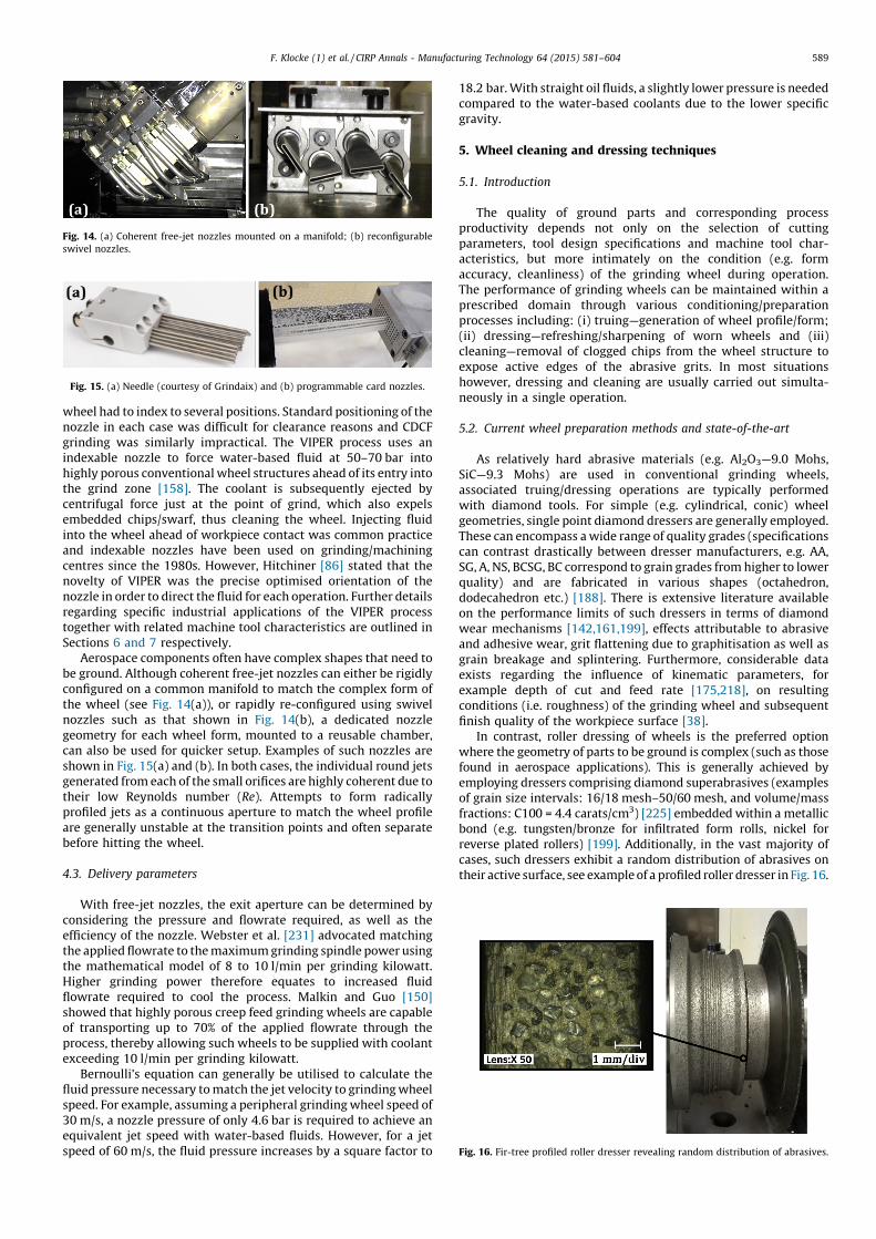
In contrast, roller dressing of wheels is the preferred opwhere the geometry of parts to be ground is complex (such as thfound in aerospace applications). This is generally achievedemploying dressers comprising diamond superabrasives (examof grain size intervals: 16/18 mesh–50/60 mesh, and volume/mfractions: C100 = 4.4 carats/cm3) [225] embedded within a metbond (e.g. tungsten/bronze for infiltrated form rolls, nickelreverse plated rollers) [199]. Additionally, in the vast majoritcases, such dressers exhibit a random distribution of abrasivestheir active surface, see example of a profiled roller dresser in Fig
Fig. 14. (a) Coherent free-jet nozzles mounted on a manifold; (b) reconfigurable
swivel nozzles.
Fig. 15. (a) Needle (courtesy of Grindaix) and (b) programmable card nozzles.
Fig. 16. Fir-tree profiled roller dresser revealing random distribution of abrasives.
flowrate required to cool the process. Malkin and Guo [150]showed that highly porous creep feed grinding wheels are capableof transporting up to 70% of the applied flowrate through theprocess, thereby allowing such wheels to be supplied with coolantexceeding 10 l/min per grinding kilowatt.
Bernoulli’s equation can generally be utilised to calculate thefluid pressure necessary to match the jet velocity to grinding wheelspeed. For example, assuming a peripheral grinding wheel speed of30 m/s, a nozzle pressure of only 4.6 bar is required to achieve anequivalent jet speed with water-based fluids. However, for a jetspeed of 60 m/s, the fluid pressure increases by a square factor to

Nbutily; sdrescy [1dresdresperf
Adiamto
[96,ontoperfmecple/prepwheconsthe w(e.g.conficomtogedresthe
VD >
typirealalter
DconvinteHowtolegrinusuadiamdresnorm
5.3.
Aelemgrinwithparacorroutp[28,aeroand
Mdiffeasso
Fig. 1EHW
F. Klocke (1) et al. / CIRP Annals - Manufacturing Technology 64 (2015) 581–604590
evertheless, roller dressers with controlled/structured distri-on (patterns) of diamond abrasives are available commercial-ee Fig. 17, which have been reported to provide superiorsing performance with improved repeatability and consisten-09,122]. In this respect, research concerning the influence of
ser abrasive size and distribution density on efficiency of thesing operation [140,147] as well as subsequent grinding wheelormance [148] and workpiece quality is well documented.lternative advanced designs of dressers involving CVDond logs oriented at preferential crystallographic directions
augment wear resistance have also been developed104,124]. Similarly, research on incorporating macro-features
the surface of abrasives in order to enhance dressingormance has been reported, particularly in the case of chemicalhanical polishing (CMP) pads for integrated circuits [219]. Sim-plain geometry roller dressers are primarily employed toare wheels used for grinding parts without complex profiles,re the associated kinematics are relatively straightforwardisting of only rotational and translational components alongheel surface. However, the grinding of aerospace components
blade root forms) frequently requires conjugate dressergurations with the process kinematics somewhat more
plicated, requiring simultaneous consideration of rotationther with in-feed motion. With regard to rotation, rollersers can operate under three different regimes, depending onvalue of the dresser-wheel speed ratio (qd= VD/VW): (i) VW/
1; (ii) VW/VD = 1 and (iii) VW/VD < 1 [81]. The roller dresser iscally motor driven (usually at a constant speed); and hence toise the necessary velocity ratios, the grinding wheel speed ised accordingly.ressing to reconstitute the geometry and grit sharpness ofentional abrasive grinding wheels is traditionally performed
rmittently (in order to preserve both dresser and wheel life).ever, due to the stringent surface integrity and dimensional
rance standards of aerospace components, many modernding centres incorporate continuous dress capability, whichlly involves the roller dresser and workpiece arranged in aetric position relative to the grinding wheel. Conversely, the
sing of CBN and diamond superabrasive grinding wheels isally undertaken using non-conventional methods.
Influence of dressing on grinding performance
s previously stated, wheel preparation is a fundamentalent of the grinding process. In order to achieve optimal
finish. An increase in dressing infeed corresponded to a decrease ingrinding forces, while for a dresser-wheel speed ratio of unity, thewheel surface roughness was found to reach a peak value. Suchdata can therefore be used together with empirical models toestimate wheel condition following dressing and consequently theresulting grinding performance.
5.4. Innovative wheel dressing/cleaning processes
The development of innovative wheel dressing and cleaningtechniques is a key research aim for the aerospace industrytowards achieving tighter part tolerances and greater materialremoval rates. Use of (abrasive) waterjets for the truing of grindingwheels with complex geometries [8] has been reported to reducewheel preparation times by a factor of >30, however the extremelyhigh fluid velocities (�1.5 � 343 m/s) required can be detrimentalto general machine tool setups and therefore this method is onlyperformed on specialist waterjet systems.
Dressing and cleaning of grinding wheels can also be achievedthrough the application of localised energy sources such as laser[37,97,229] and electrical-discharge [46,119,233] based processes(see example schematics in Fig. 18), leading to improvements interms of grinding performance. For instance, lower grinding forceswere recorded (up to 1.5 times for the normal component)following laser dressing as opposed to conventional wheel dressing[183]. While such techniques have been successfully demonstrat-ed under research/laboratory conditions, further validation trialswithin semi-industrial environments are imperative to allow formore robust evaluation prior to transfer onto actual productionlines.
6. Industrial perspectives of abrasive machining
Gas turbine engine manufacturers are continuously formulat-ing and introducing new elevated temperature strength alloyssuch as those discussed in Section 3 for realising greater fuelefficiency. This has necessitated the development of moreadvanced manufacturing process technologies and strategies toovercome the increasing difficulty in machining such materials.
6.1. Overview of abrasive machining processes in the aerospace
industry and current practices
Grinding processes are extensively utilised for producingfinished part geometry on a variety of aeroengine components
7. Roller dresser with structured/deterministic grain distribution [courtesy of
A Diamond Ind. Co.].
Fig. 18. Example schematic of (a) laser dressing [97] and (b) wire electrical
discharge dressing/trueing [119].
ding performance, wheel conditioning must be carried out appropriate selection of dresser design and operatingmeters. In this respect, published literature highlights severalelations between the dressing setup and grinding processuts. Despite the development of numerous analytical models
141], dressing process control techniques used in thespace industry are still mainly based on empirical analysisexperimental results.alkin and Murray [147,148] evaluated the influence of
rent abrasive characteristics in rotary dressers together withciated operating parameters on grinding forces and surface
ranging from root and shroud features on turbine/compressorblades to vanes, shafts, seal segments etc., whether in the cast,forged or fabricated state. In addition to demands for achievingtight tolerances, fine surface finish and high surface integrityfollowing machining, efforts are continuously directed towardsincreasing levels of process efficiency, reducing costs andimproving customer satisfaction. Grinding is often the preferredoption over alternative machining methods, due to its consistentability for achieving sub-10 mm accuracies, fine levels of surfacefinish below 1 mm Ra and high stock removal with Q0w generally inexcess of 100 mm3/mm s.

icalsses
oreideslexese
forgu-ucheedBN
nce,ightingany
outhenallyiscskel-lexhin
areionpleicalTheted
Mo
2
n off
F. Klocke (1) et al. / CIRP Annals - Manufacturing Technology 64 (2015) 581–604 591
Apart from geometrical/dimensional and surface qualityrequirements, the as-supplied material condition of the compo-nent has a major effect on grinding process capability. Conse-quently, numerous grinding process modes are utilised, rangingfrom cylindrical, reciprocating, continuous and intermittent dress(CD and ID) creep feed grinding, VIPER grinding, speed strokegrinding as well as other more specific applications such as rotorblade tip grinding, curvic, spline and gear grinding, depending onthe product group and specific manufacturing strategy. The rotorblade tip grinding process is used to grind blade tips of a rotorassembly to a very high precision, enabling a tight fit between therotating blades and the outer sealing components for increasedengine operating efficiency. Grinding of curvic couplings istypically performed using a cup-type grinding wheel mountedon a high precision vertical cylindrical grinding machine. Thesetypes of couplings are commonly used in jet engines for achieving apositive drive, high component centring accuracy and high loadcarrying capacity along the main engine shaft. However, the rangeof equipment used for different components can vary from simple3-axis surface grinders to complex 6-axis integrated grinding cellsas well as bespoke blade tip and curvic grinders. Key characteristicsof machine tools/equipment employed in aerospace grinding arediscussed in Section 7.
The Rolls-Royce plc patented VIPER process [82] is appliedextensively for the manufacture of root profiles and features inturbine blades as well as vanes and other aerospace components;see example in Fig. 19. Precise location of the fluid jet is maintainedthroughout the wheel life by a programmable coolant nozzle (PCN)system, with 2-axis NC driven, 3608 positioning capability. Highstrength bond systems and induced porosity characteristics ofAl2O3/ceramic wheels employed in the VIPER process provideenhanced capacity for chip and coolant retention together withimproved form/profile preservation. The method allows machiningat significantly lower temperatures compared to conventionalcreep feed grinding, reduced mechanical and thermal loads (lowerrisk of workpiece thermal damage), extended wheel life (reducedwheel cost) and scope for operating at more aggressive parameters(larger depth of cut, increased feed rate etc.). This leads to a majorincrease in productivity, with Q0w values of up to 100 mm3/mm sunder intermittent dressing mode, rising to 300 mm3/mm s in CD
configuration, see Table 3 for the benefits, challenges and typspecific material removal rates of the various grinding proceutilised in aerospace applications.
In recent years, use of superabrasives has become mprominent in the aerospace sector, particularly as it provgreater flexibility for low-volume production runs. Compprofiles can be generated with electroplated CBN wheels. Thcan be produced through precision machining of wheel hubsform grinding. Despite being the most widely employed confiration, electroplated CBN grinding has inherent shortcomings sas transient performance, large wheel life variations and the nfor oil-based fluids [84]. In contrast, dress-able vitrified Cwheels offer greater consistency in terms of grinding performawhich is suitable for high-volume applications requiring ttolerances and smooth surfaces. In addition, vitrified CBN grindcan be carried out with water-based coolant without
significant detriment to wheel life [85].
6.2. Workpiece materials and process developments
Achieving acceptable workpiece surface integrity withadverse effects on material properties is a major challenge wgrinding nickel-based superalloy components such as integrbladed rotors (IBR) for high-pressure compressors (HPC) or dfor high-pressure turbines (HPT) within an aeroengine. Nicbased superalloys generally contain fine carbides having compcompositions (mainly WC, MoC and to a lesser degree NbC) wita ductile (Co, Ni, Cr) matrix phase. The fine-grained carbidesusually evenly distributed in the structure, which has low coheswith the matrix and are easily torn off even during sampreparation (polishing and etching), see Fig. 20(a). The typcomposition of a nickel-based superalloy is outlined in Table 4.
hardness of the alloy is �46–47 HRC and results in elevastresses at the tool/workpiece interface during machining.
Fig. 19. VIPER grinding of turbine blades [168].
Table 3Maximum achievable Q0w for different grinding processes employed in aerospace applications together with associated benefits and challenges.
Grinding process Q0w (mm3/mm s) Benefits Challenges
Table 4Typical elemental composition of nickel-based superalloys.
Elemental composition, %
Al Ti Cr Co Ni Nb W Ta
14–18 2.5 12–14 18–20 40–44 1 2.5–3.0 1
Fig. 20. Etched micrographs of nickel-based superalloy core material; (a) tor
carbides; (b) high resolution SEM micrograph.
Surface grinding 10 Low complexity, equipment investment low Low productivity and poor wheel profile holding
Intermittent dress (ID) CFG 20 Low complexity Low productivity and poor wheel profile holding
Continuous dress (CD) CFG 50 High wheel profile holding capability Moderate productivity, high abrasive and dressing
roll consumption
CFG with CBN wheels 20 High wheel profile holding capability Low productivity, high wheel cost and need for
high rigidity equipment
ID VIPER grinding 100 Good productivity, low wheel cost per part, multifunctional
machines
Moderate wheel form holding
CD VIPER grinding 300 Excellent productivity, high wheel profile holding capability.
Multifunctional machines
High equipment investment cost, high abrasive and
dressing roll consumption
Speed stroke grinding 100 High wheel profile holding capability, low cutting forces Very high wheel and table speeds, equipment
maintenance and lifecycle cost

Cto bthe
(Al–highvarigenelife ospee
Tthemprocfullycomleadcarbimpsupemicrperivarythicand
ing
enerspec30 tmat(effi
Tintehighmatals hto tformcostinte
Ccm3
comsignnatecannof C
Fig. 2whee
F. Klocke (1) et al. / CIRP Annals - Manufacturing Technology 64 (2015) 581–604592
onventional machining of nickel-based superalloys has provene challenging as it usually generates WEL (white-etch layer) oncut surface, which is composed of a metal-ceramic compoundW–O). This layer has poor adhesion to the substrate, with very
concentrations of WC particles. The thickness of the WELes depending on the machining speed and amount of heatrated. White-etch layers directly impact the fatigue strength/f critical rotating parts. Fig. 21 shows the influence of cuttingd on the thickness of WEL in a nickel-based superalloy.he relatively high hardness of nickel-based superalloys makes
more favourable to grinding rather than conventional cuttingesses. Cubic boron nitride superabrasives have been success-
utilised to machine various superalloy gas turbine engineponents. The hardness of CBN abrasives (4500 kg/mm2) [149]s to significantly lower wheel wear compared to coatedide milling tools, resulting in reduced tooling cost androved process consistency. Fig. 22 shows a schematic of therabrasive machining (SAM) process [71] together with a SEMograph of a CBN electroplated tool. The CBN abrasives on the
phery of a grinding wheel produce extremely small chips ofing thickness, width and shape. The typical range of chip
kness varies from 2 to 50 mm depending on the wheel grit sizemachining parameters. This can lead to considerable plough-and rubbing (particularly at smaller chip thickness), wheregy is expended without any significant material removal. Theific energy required to grind one cubic millimetre is 10 to
imes higher than that required to machine the same volume oferial under uniform chip thickness and shape conditionscient/consistent chip formation process).he expanding use of composite (e.g. MMCs and CMCs) andrmetallic (e.g. g-TiAl) alloys in the aerospace industry requiresly engineered solutions based on effective integration oferials and manufacturing technology. These advanced materi-ave further driven the application of grinding operations, due
alloys have been successfully ground using a range of grindingmethods (surface, CFG, VIPER, speed-stroke and high efficiencydeep grinding—HEDG) and abrasives (conventional SiC and Al2O3;and superabrasive CBN and diamond), the reported metal removalrates necessary to achieve acceptable part quality are relativelylow (Q0w < 15 mm3/mm s). Similarly, the unique challengesassociated with grinding of CMC materials have led to investiga-tion of alternative methods, such as ultrasonic assisted grindingusing rotary diamond abrasive tools [168]. These are two exampleswhere major improvements in process efficiency and reliability arerequired for grinding to become cost effective.
Despite rapid developments in additive layer manufacturing(ALM) and associated ‘near net shape’ fabrication technologies,finish machining operations such as grinding are still necessary toachieve required component surface roughness and topographytolerances. In such applications, the focus of grinding processdevelopment has primarily centred on stable form/profile genera-tion capability as well as minimising thermal and mechanicalloads, rather than improving stock removal rates.
6.3. Productivity characteristics/costs
The perpetual drive for continuous improvement in grindingperformance is largely aimed at reducing process costs and lead-times, while improving component quality. While the reduction ingrinding lead times is generally reliant on high process/equipmentavailability and reliability, understanding the costs of each processelement allows development activities to be targeted at areas thatprovide maximum returns. Key to achieving predictable anddesirable outputs (component quality, process capability, opera-tional efficiency and cost), is strict control of grinding processinputs that directly influence both the capability and overall cost,which is illustrated in Fig. 23. These include: (i) process parametersand cut strategy; (ii) machine axis alignments (setting variation,environmental impact), accuracy of part alignment to machine tooldatums (loading repeatability, fixture to fixture, part datum andsetting variations); (iii) fixture capability to hold componentsaccurately and rigidly; (iv) coolant application parameters (nozzlegeometry, position, condition, coolant flow, pressure, temperature,concentration) and (v) operator intervention in part, fixture anddresser settings on machines, inspection of repeatability andreproducibility, operator touch-time required to complete process,dresser and wheel wear/life etc.
Recent grinding strategies adopted in the aerospace industry,particularly in high-cost economies, are based on a ‘single machinevisit’ approach, with the aim of minimising the number ofmachining operations, throughput time and operator intervention.This commonly involves fully automated, integrated machiningcells (based on latest generation multifunctional machiningplatforms) and adaptive close loop feedback grinding andinspection processes. An essential part of this strategy is theapplication of advanced high efficiency grinding methods, cut
Fig. 21. Variation of white-etch layer thickness vs. cutting speed.
2. (a) Schematic of SAM process [71]; (b) SEM of CBN grits on an electroplated
l (courtesy of J. Badger).
Fig. 23. Grinding process inputs and outputs (courtesy of Rolls-Royce).
he increased difficulties encountered by alternative chiping processes when trying to achieve high efficiency and
effective machining while maintaining appropriate surfacegrity conditions.haracterised by low density (�2.5 g/cm3 for CMC and �4 g/for TiAl) and high temperature capability, ceramic matrix
posites and Ti-based intermetallics can potentially offerificant performance benefits for gas turbine engines. Unfortu-ly, the advantages of high stock removal grinding processesot be fully exploited here, due to the increased susceptibility
MCs and g-TiAl to machining induced damage. While g-TiAl

tionThes inedsing
lexhlycal-mi-AMh asThe bya isces,d inntlyuce
theTheess
aniple
theandller
temion,lant
ls for
ent;
F. Klocke (1) et al. / CIRP Annals - Manufacturing Technology 64 (2015) 581–604 593
strategies, wheels and dressers, robust intelligent fixturingsolutions, process variable monitoring and control, advancedinspection techniques as well as integrated mechanised edgeprofiling and de-burring operations; see Fig. 24. Such an approachhas been shown to result in significantly improved processcapability, reduced lead times and cost [138].
Future aerospace industry requirements include processimprovements based on minimising total life cycle investmentcosts and establishing a flexible operating environment capable ofmeeting the constantly evolving landscape of the business.
6.4. Industry case studies
Grinding with superabrasives has been successfully utilised as aviable alternative to conventional cutting operations for themanufacture of several components in gas turbine engines. Thefollowing sections detail two industrial examples; (i) SAM ofnickel-based superalloy IBR airfoils previously machined byconventional milling and (ii) turn-grinding of HPC and HPT parts,which replaced conventional turning.
6.4.1. SAM of nickel-based superalloy IBR airfoils
complex-shaped airfoils. An example of a SAM finishing operais shown in Fig. 25(b), which utilises electroplated CBN quills.
quills perform a combination of flank and point SAM operationorder to fabricate the complete airfoil shape. Here, spindle speof up to 120,000 rpm are used to control chip load while achievthe required metal removal rate.
Under multi-axis SAM using wheels and quills with compgeometries, the tool–workpiece contact geometry is higcomplicated and non-uniform, hence difficult to model analytily. A generalised process simulation and multi-constraint optisation technique has been successfully developed for five-axis Sto increase material removal rate while avoiding problems sucdamage to machined surfaces and premature tool failure [78].
tool–workpiece contacts are extracted from a CAM systemgeometrically processing the NC program. The geometric datthen used to predict physical process parameters such as forpower, and temperature using the grinding models as illustrateFig. 26. Multi-constraint optimisation strategies are subsequeapplied to identify preferred process parameters in order to redcycle time.
Spindle monitoring systems play an important role in
success of SAM for manufacturing nickel IBR airfoils.
application of such techniques provides protection against procand machine failures during part production. Fig. 27 showsexample of a spindle monitoring system, which employs multembedded sensors that continuously assess the conditions ofcutting process and spindle. It applies real-time data analysis
decision-making algorithms to provide the machine controwith appropriate corrective measures when necessary. The systracks variables such as power consumption, bearing vibratspindle growth, motor temperature as well as spindle coo
Fig. 24. Holistic approach to grinding process design [168].
Fig. 25. SAM of nickel superalloy IBR airfoils using electroplated CBN (a) whee
roughing; (b) quills for finishing.
Fig. 26. SAM process modelling and simulation of (a) tool-workpiece engagem
(b) cutting forces; (c) tool design optimisation.
Fig. 27. Example schematic of a SAM spindle monitoring system.
Superabrasive machining is an enabling technology for theefficient and economic manufacture of nickel-based superalloy IBRairfoils [63,64], which has been developed as a replacement forconventional milling. Fig. 25(a) shows a single layer electroplatedCBN roughing wheel performing an open pass in-between the rotorairfoils. Cutting speeds of up to 100 m/s are employed to achievespecific metal removal rates of 10 mm3/mm s or higher. Theprocess however requires an oil-based grinding fluid supplied atpressures up to 60 bar, which has proven to be more efficient withelectroplated CBN wheels and quills [72]. A combination of straightand cup-shaped wheels are utilised to allow the production of

temdetecontabnomai
AgeomprogflowfaulmacFig.
macfailuor ldepeprogconfispec
6.4.2
Cfor
advaexcespeeexamof aoperturblife
AvitriFig.
diamwhe
Fig.
conv
F. Klocke (1) et al. / CIRP Annals - Manufacturing Technology 64 (2015) 581–604594
perature and flow. The system has the ability to flag anyrioration in spindle performance and instructs the machineroller to protect the machined part in case of any operationalrmality. It also plays a role in the integrated machine
ntenance system.s the application of SAM progresses from grinding of simpleetries to 5-axis machining of airfoils, the need for intelligent
rammable coolant delivery systems with accurate control of becomes imperative. Similarly, it is critical to monitor for
ts that may occur in the coolant supply system duringhining. The active coolant flow control strategy detailed in28 utilises programmed logic to avoid workpiece and/or
hine destruction due to inefficient fluid supply or hardwarere caused by fire [136]. The system can detect nozzle blockage
eakage where the controller issues various levels of alarmsnding on the severity of the problem. It also allowsrammable coolant nozzle setups to accommodate differentgurations on the machine tool. Each nozzle’s flowrate can beified individually based on functionality and nozzle profile.
. Turn-grinding of HPC and HPT rotors and discs
onventional single point turning has proven to be inefficientthe machining of newly developed materials/alloys withnced mechanical/physical properties. It is characterised byssive tool wear (tip breakage and chipping), low cuttingds/productivity and poor workpiece surface integrity, seeples shown in Figs. 29 and 30. This has led to the development
n abrasive based process known as turn-grinding [60]. Thisation can be used for processing several part families in gasine engines such as HPT and HPC rotors, where the functionalis heavily influenced by the quality of the machined surface.
variety of abrasive wheels such as single layer electroplated orfied CBN or diamond wheels can be used for turn-grinding.31 details a schematic of a turn-grinding operation for innereter machining together with an example of a turn-grinding
el. The wheel is mounted on a spindle, which can produce
peripheral surface speeds of up to 100 m/s. Conversely, theworkpiece rotor is installed on a rotary axis, which is capable ofrotational speeds up to 2000 rpm. The turn-grinding wheel is thentraversed along the workpiece surface to produce the desiredgeometrical feature.
Amongst the principal advantages of abrasive wheels used inturn-grinding compared to single point tools include the higherhardness of the grains, greater number of cutting edges on thewheel circumference and increased speed of chip removal. In turn-grinding, the chip load on each grit is very small, which limits themachining forces and heat generated, resulting in componentswith superior surface quality and lifing characteristics. Further-more, the high cutting speeds employed leads to an optimum shearrate of chips.
Fig. 32 shows the variety of features on a HPT rotor that can beproduced via turn-grinding. Feature dimensions and part geometrylargely determine the wheel size/shape, cutter path and orienta-tion used during machining. Extension shafts can be attached toincrease wheel reach and avoid collisions, with wheel tapersadjusted to clear part geometry. Similarly, wheel tip radius can bemodified to match the required final fillet radii on the workpiece.Typically, wheel diameter is dependent on spindle rotational speedcapacity in the case of outer diameter turn-grinding while for innerdiameter operations, accessibility within the workpiece is thegoverning factor.
Fig. 28. Active coolant flow control system [136].
29. Typical surface defects due to torn and dragged carbides when using
entional turning inserts.
Fig. 31. (a) Schematic of turn-grinding operation; (b) example of turn-grinding
wheel.
Fig. 32. Turn-grinding of HPT rotor.
Fig. 30. Typical failure patterns of conventional turning inserts.
Turn-grinding however requires a more efficient method tofacilitate coolant delivery into the machining zone compared toconventional cutting processes. Fig. 33 shows the application of acentrifuge-assisted, coolant-through superabrasive grindingwheel for turn-grinding of a HPC impeller [59]. The flexible fluiddelivery technique can be applied to wheels with varying shapes/sizes or configuration. Coolant is supplied as close as possible to themachining zone at velocities equal to the wheel circumferentialspeed, which effectively disrupts any air barrier that forms aroundthe wheel. The method also overcomes the limitation ofconventional spray nozzles that require line of sight operation.

set- be
inilityity.eenrialust
ring theur-in-
sedlingino
temtionciseher
jet the
cedich
andtion
ascedeanthatnceaveting
ding
F. Klocke (1) et al. / CIRP Annals - Manufacturing Technology 64 (2015) 581–604 595
Fig. 34 shows sample cross sectional micrographs of nickel-based superalloy surfaces produced following turn-grinding. Theworkpieces were found to be free of surface defects such asdistorted grain structures, WEL or fractured carbides, whichenhanced the fatigue life of gas turbine engine components.
7. Machine tools and related aspects
As discussed previously, the most suitable materials foraerospace applications are those with excellent mechanicalstrength and resistance to surface degradation particularly atelevated temperatures. Such materials however pose considerablechallenges for manufacturing. Grinding is still the most efficientmethod for achieving the tight profile tolerances and accuraciestypically required in aerospace components [216]. In recent years,significant effort has been invested to increase productivity andprocess stability when grinding aerospace alloys, althoughpublished technical information by original equipment manufac-turers (OEM) are rare. With this in mind, the following section willdiscuss the current state-of-the-art relating to dedicated grindingmachine tools in the aerospace industry as well as ideas andmonitoring concepts that advance grinding technology.
7.1. Specific machine tool configurations
In combination with near net shape casting technology, highvolume components such as turbine blades in particular are oftenmachined to final shape via creep feed grinding. The principaloperating characteristic of CFG is the combination of slow tablefeeds and relatively large depths of cut (�1–10 mm). The grindingallowance is generally achieved in a few passes, which enablesincreased specific material removal rates (Q0w) in comparison toreciprocating grinding [116,181]. To stabilise the process andreduce heat generated during grinding (that can result inundesirable thermal fluxes into the workpiece), the wheel profileis constantly maintained during machining using a diamond roller
dressing different grinding wheel topographies and decrease
up times (by up to �75%), a dual-spindle dressing system canimplemented on the machine tool [26,154].
External grinding of complex aeroengine componentsassociation with CDCF configuration increases process versatcombined with an improved Q0w that optimises productivHowever, because of the different engagement conditions betwthe abrasive wheel and workpiece, heat transfer into the matesurface can vary significantly. Therefore, the coolant supply mbe suitably adapted so that the pressure angle of the fluid jet dugrinding is correctly aligned. This ensures the performance ofgrinding process and surface integrity of the workpiece [88]. Fther increase in productivity is possible by incorporating a twwheel concept for turbine blade creep feed grinding [118].
Several machine tool suppliers including Makino have licenthe patented VIPER process [82] that enables simultaneous cooand cleaning of the grinding wheel during operation. The Makmachine incorporates a special programmable nozzle syscapable of accurately controlling fluid direction and orientarelative to the wheel circumference together with preregulation of coolant pressure; see Fig. 36. The design furtallows an appropriate angle of contingence for the coolanthitting the abrasive wheel and hence controls the gap betweenwheel and exit tip of the nozzle [184].
Another dedicated machine tool for grinding advanaerospace materials was recently developed by Blohm, whexploits the combination of high grinding speeds (�160 m/s)
worktable feeds (up to 200 m/min) to reduce heat generaduring operation [249]. This process is commonly referred to‘speed stroke grinding’ (SSG). The original concept was introduin 1988 by Inasaki [105], followed by the first joint Europproject to develop a suitable machine tool platform [215]
initially involved ball screw-nut based table drives. This has sibeen largely replaced by advanced linear direct drives that henabled higher feed speeds as well as increased oscilla
Fig. 33. Centrifuge-assisted coolant-through superabrasive wheel in turn-grinding
of HPC impeller [59].
Fig. 34. Near-surface workpiece microstructure post turn-grinding of a nickel-
based superalloy.
Fig. 35. Example and schematic of continuous dress creep feed (CDCF) grin
operation (courtesy of Blohm).
Fig. 36. VIPER grinding machine tool and operational configuration [184].
in a continuous dress creep feed (CDCF) grinding configuration,which is illustrated in Fig. 35.
The diamond roller is positioned above the wheel and iscontrolled by a separate CNC axis, which removes a thin layer ofabrasives from the active surface of the wheel with each incrementin radial infeed. Consequently, the wheel topography remainseffective and clean. This results in good form accuracy and highstock removal rates coupled with low cycle times as well asreduced heat flux into the component. The CNC control alsoactively compensates for the continuous reduction in grindingwheel diameter [217,232]. In order to achieve greater flexibility for

freqcomminworredutranenerthe
voluabraconv
Aqualzoneup tdefeTherachidimfinismacconsdamthe
acceM
energrinIt wcut acritiwithcorrinitivw rtemelevresidat in
Afeedaeroadvawhenecedowmatsoludiffestormactop
Fig. 3on a
F. Klocke (1) et al. / CIRP Annals - Manufacturing Technology 64 (2015) 581–604596
uencies, which are fundamental requirements for SSG [216]. Inparison to creep feed grinding (typical feed rate of 0.1–1.0 m/) [1], SSG involves much faster feed rates and shorter wheel-kpiece contact lengths. Hence, cutting forces and friction areced while chip thickness increases, which leads to greatersport of heat away from the grinding zone. Consequently, lessgy is conducted into the surface of the component and hence
risk of surface integrity damage even when grinding with lowmes of coolant is reduced [171]. In addition, wear of thesive wheel was reported to be up to 80% lower thanentional CFG processes [107].
further advantage of SSG relates to the resulting surfaceity. Due to the higher amounts of heat generated at the cutting, CDCF grinding can result in workpiece damage that extend
o 80 mm below the machined surface. In contrast, the depth ofcts in surfaces produced by SSG does not exceed 8 mm.efore even under roughing conditions, SSG is capable ofeving relatively close tolerances with respect to the finalension, which minimises the remaining stock allowance forhing and reduces overall process time. Additionally, specialisthine tools designed for SSG such as the Blohm Prokos has beentructed with a mineral cast bed to provide appropriateping characteristics in order to eliminate vibrations caused byhigh dynamic process kinematics, and to absorb high
leration pulses, see Fig. 37 [171].ore recently, Zeppenfeld [248,249] developed tool wear,
gy and crack formation prediction models when speed strokeding of g-titanium aluminide (Ti–45Al–2Mn–2Nb + 0.8% TiB2).as shown that wheel wear was minimised by reducing depth ofnd increasing table feed (vw), with 120 m/min identified as the
cal value. Specific grinding energy was also seen to decrease increasing table feed up to 200 m/min. Additionally,
esponding workpiece surface residual stress shifted from anally tensile mode at vw = 50 m/min to a compressive regime asose above 100 m/min. This was due to the reduction in cuttingperatures as a result of shorter tool-workpiece contact times atated table feeds. However, despite the presence of compressiveual stresses, workpiece cracking was evident when operatingcreasing specific material removal rates.lthough based on contrasting operating principles, both creep
and speed stroke grinding have found their way into industrial
machine tool flexibility, but also substantially reduces cycle andidle times.
A number of grinding centre manufacturers currently offerproduction machines with up to six simultaneous axis operations.Equipped with powerful CNC processors, such systems provide thecapability for precise path controlled contour grinding of complexaeroengine components combined with enhanced productivity.Even parts with larger radii can be ground using a continuous-pathcontrolled grinding cycle as demonstrated in the example shownon the right of Fig. 37 [171].
Fig. 38 shows a customised grinding machine tool designed forthe precision manufacturing of aircraft landing gears. Forged gearstruts are highly unbalanced due to the asymmetric section of thewheel-mounting axis, which requires the installation of counter-weights together with an extremely large working diameter formachining. The grinding machine shown in Fig. 38 allows aswivelling diameter of up to 4 m [49].
The turbine blade tip grinder is another example of a special-purpose grinding system developed for aerospace componentmanufacture [50], with the operating set-up detailed inFig. 39. Here, the machine tool grinds the blade tips as the rotoris rotated at high speed, thereby providing appropriate operatingconditions between the wheel and workpiece feature. The processensures a high degree of accuracy with reported diametrictolerances down to 0.025 mm. This level of precision is deemedessential as the clearance distance between the rotor blade tips andouter housing has a critical bearing on engine performance [50].
Apart from innovative machine tool systems, productivity inaerospace grinding can also be enhanced via efficient abrasivewheel cleaning technology as discussed in Section 5. In severalprocesses, continuous dressing can be substituted with an intervalplunge dressing (IPD) strategy. Consequently, grinding processesthat utilise conventional abrasives such as corundum or siliconcarbide can be improved in terms of optimised material removalrates and lower wheel wear [172]. In addition, environmentalissues relating to abrasive machining in production are importantconsiderations. While reducing energy consumption is an increas-ing priority within the aerospace industry, this must be balancedagainst the specific boundary conditions of precision grindingprocesses [6].
7. Automatic tool changing system and continuous path controlled grinding
Blohm Prokos machine tool (courtesy of Blohm).
Fig. 38. Machine tool for grinding landing gear struts (courtesy of Danobat).
Fig. 39. Machine tool designed for grinding turbine blade tips (courtesy of Danobat).
space manufacturing applications due to their respectiventages described previously. However, the rate of grindingel consumption in both process configurations is considerable,ssitating frequent tool replacement and increases machinen time especially under manual operation. Therefore, auto-ic grinding wheel changing systems were introduced as ation to enhance process productivity. A combination ofrent conventional and CBN grinding wheels are generally
ed in the tool change magazine to facilitate completehining of complex parts in one set up, as highlighted in theleft image of Fig. 37. Indeed, this approach not only improves

ingy inledsedms
ary,up-Forit isn a
theble
beith
tingdelsrorsing
l as to
ratetingssorons,apeion,derfersrger
ckeling.
hassts,es,
rces
F. Klocke (1) et al. / CIRP Annals - Manufacturing Technology 64 (2015) 581–604 597
It is likely that many more specialised machine tools foraerospace grinding applications exists, however as previouslystated, related information in the public domain is limited. This islargely due to the highly competitive nature of the aerospaceindustry where technological developments tend to be proprietaryor classified.
7.2. Work holding and fixturing
Proper part fixturing and work holding during grinding isessential to achieving desired surface finish and component quality.In general, greater workpiece holding rigidity corresponds to higherattainable material removal rates [184]. Therefore, two principalmethods for securing workpieces during machining have beenestablished in recent years. The first is the hardpoint procedure thatrequires a device to clamp the component at various locatingsurfaces while the second technique involves encapsulation of theturbine blade with a specific zinc alloy that subsequently securesthe cast part at defined positions. This allows for easy and precisetransport of cast-in components between different process stations.The latter technique however imposes additional working stepsincluding casting and cleaning of the component [154].
For loading and unloading of the machine, a conveyor system inconjunction with a suspended positioned robot arm represents anefficient approach for workpiece handling. In comparison toconventional solutions, this reduces the need for rigorous safetyregulations. It also improves accessibility to the workspace of themachine and optimises the loading process when employed intandem with a conveyor equipped with video-based componentand fixture recognition. Consequently, the shorter path from theconveyer via robot to the machining area reduces time for loadingand unloading of parts [154].
7.3. Monitoring of aerospace grinding processes
Considering the fact that grinding is a relatively complex anddemanding operation, sensor systems to detect malfunctions areessential. Many of the process monitoring techniques used ingeneral abrasive machining can also be applied to aerospacegrinding applications. The details and characteristics of variousgrinding monitoring systems have been reviewed in several keypublications [106,115].
As with most complex manufacturing operations, the preferredoption for investigating the influence of grinding on resultingproperties of the workpiece material is through direct non-destructive measurement of the machined surface [106]. Unfortu-nately, even to date, there are very few detection systems capableof meeting this demand. Of the available instruments however, thetechnique based on eddy currents has demonstrated the greatestpotential especially for the inspection of fractures in turbineblades. The principle of eddy current measurement is based on thetheory that any cracks present in the workpiece surface (placedwithin the measurement region) will disturb the eddy current fieldgenerated from an alternating-current excited coil. This method-ology is applicable on any electrically conductive workpiecematerial.
Eddy current sensors were first introduced approximately20 years ago to monitor cracks generated during profile surfacegrinding of turbine blade fir-tree roots, see Fig. 40. The system
In addition to surface integrity evaluation, sensors for assesscomplicated geometry features are also available and currentluse. The measurement of blade tips on fast rotating assembturbines (see Fig. 39) can be performed either by laser bamethods [146] or via non-contact capacity based syste[186]. Where a more sophisticated approach is necessmonitoring and control through a model-based simulation sported by in-process measurement is a potential option.
instance, when grinding fir tree profiles on blade root sections,
essential that resulting grinding forces be maintained withicritical threshold during the process in order to avoid damagingspecial coating on the blade airfoils as well as to ensure acceptasurface integrity. Consequently, grinding force and heat flux canindirectly estimated from the recorded spindle power, wdeviations from the normal process signature profile indicapossible process issues [76]. Based on results from grinding motogether with in-process data, it is possible to assess form erthrough correlations between monitored tangential grindforces/power and workpiece material characteristics as welpredictions from finite element (FE) simulations. This leadsenhancement of grinding process stability and quality [133].
8. Innovative abrasive processing operations
8.1. Point grinding of blade root slots in discs
The majority of modern aeroengine designs still incorporotor components with detachable blades. The series of mounslots that locate and secure the blades to the turbine/comprediscs principally comprise two main geometry configuratidovetail and fir-tree [102]. The former is a relatively simple shand can be employed in an axial or circumferential orientatwhile fir-tree profiles are more complex and used primarily unhigh blade loading conditions. The profile of the latter slot ofmultiple areas of contact in order to accommodate much laloads [155].
Industrial production of blade root mounting slots in nibased superalloy discs is currently dominated by broachDespite being a mature and validated technology, the processseveral significant disadvantages including high capital cocomplex and expensive tool design/regrinding, long setup timlarge floor space requirements together with high process fo
Fig. 40. Eddy current crack inspection.
hasich
also
allandnel
byofiting
was
employed a bridge-type measuring gauge equipped with a suitablesensor that scanned over the ground surface [236]. While crackdetection was possible, the apparatus response time wasconsiderably slower compared to the grinding table speed, whichprevented real time assessment and meant that measurementshad to be performed post operation. Furthermore, only cracks onthe ground workpiece surface could be reliably identified.Nevertheless, the concept proved to be valid and has led to thedevelopment of geometry adapted sensors for fir-tree discs, whichare commercially available for fast post-process crack inspection[58], as shown in the bottom right image of Fig. 40.
and poor flexibility. A potential alternative to broaching that
been developed over the past �15 years is point grinding, whemploys profiled superabrasive grinding wheels/points (commonly referred to as quills).
Preliminary research to investigate the feasibility of using smdiameter (15 mm), plain electroplated superabrasive (CBN
diamond) grinding wheels for plunge edge grinding Inco718 and Udimet 720 nickel based superalloys was reportedBurrows et al. [31,32]. The grinding points were held in a retr60,000 rpm spindle mounted on a prismatic high speed machincentre, see Fig. 41. A Taguchi fractional factorial design

empincluand
forc80 NVolurangcondIncoutili
SinteplainAspitionof 13for Urevemeaexteappe(up
Ifatiging
resuthe
wasin F
Fig. 4grind
Fig.
corre
Fig. 4[200]
F. Klocke (1) et al. / CIRP Annals - Manufacturing Technology 64 (2015) 581–604598
loyed to assess the influence of different process variablesding wheel speed, feed rate, depth of cut, grit size, friability
fluid pressure, each at 2 levels. Tangential and normal grindinges were relatively low, which varied between 20–30 N and 60–
when employing new tools, irrespective of grit type.metric material removal achieved at wheel failure howevered between 3.6 and 120 cm3 depending on operatingitions. Workpiece surface roughness down to 1.2 mm Ra on
nel 718 was obtained following spark-out passes whensing fine-grained CBN abrasives.ubsequent work to assess resulting workpiece surfacegrity following machining of Inconel 718 and Udimet 720 using
grinding points were reported by Soo et al. [200] andnwall et al. [3]. The confirmation trial utilising the combina-
of preferred operating parameters achieved a volume removed0 cm3 with a corresponding surface roughness of �1.5 mm Radimet 720. Analysis of workpiece subsurface microstructure
aled minimal plastic deformation, although microhardnesssurements indicated a softened layer at the machined surfacending to a depth of �50 mm; see Fig. 42. This however did notar to affect surface residual stresses, which were compressive
to ��700 MPa) in all of the specimens evaluated [3].nitial 4-point bend trials were undertaken to compare theue performance of point ground surfaces against correspond-high speed milled and polished Inconel 718 samples. Thelts clearly showed that at a maximum stress level of 700 MPa,number of cycles to failure for the ground specimen (1 � 107) 5 times longer than the milled surface (2 � 106); see S–N curveig. 43 [200].
Based on the initial work with plain tools, finishing trialsutilising fir-tree profiled grinding points were carried out byAspinwall et al. [5]. The influence of grit size (B46, B76 and B91),abrasive type (B46 and D46) and spindle rotational speed(60,000 rpm and 90,000 rpm) on wheel wear and workpiecesurface roughness following machining of Udimet 720 withsynthetic PAO oil was investigated. The CBN abrasive showedconsiderably lower wear rates compared to diamond, althoughworkpiece surface roughness improved with the latter. Wear rateof the B46 tool was gradual after an initial spike at trialcommencement, which can be eliminated by ‘pre-conditioning’the wheel prior to use. Workpiece surface roughness typicallydecreased with increasing volume of material removed whileincreasing spindle speed from 60,000 to 90,000 rpm led to areduction in wheel wear rate. Further development of theprocess resulted in surface roughness down to 1 mm Ra afterfinishing, with associated material removal rates up to 860 mm3/min [45]. Curtis et al. [47] proposed a possible machiningstrategy/route for point grinding of fir-tree root slots. Thisinvolves a 4-stage procedure beginning with a plain pre-slotmachined by CFG or an alternative process. A rough pointgrinding operation (large grit size) to generate the fir-tree profileis then carried out, with final sizing and surface finish/integrityrequirements achieved through successive semi-finish and finishpasses using grinding points having appropriate grain sizes anddimensions.
While point grinding is deemed as a viable process for themachining of blade root mounting slots in aeroengine discs, therehave also been parallel developments of competing technologies toaddress this application. Examples include abrasive waterjetcutting [62], wire electrical discharge machining [61,123], millingwith profiled cutters [12,13], abrasive machining with speciallyshaped wheels [132] and other adaptations of the point grindingprocess. The latter is exemplified by numerous patents[75,151,176,190] recently filed by major aeroengine manufac-turers, which suggests a high probability of current industrialapplication of the technology.
8.2. Ultrasonic/vibration assisted CFG of aerospace alloys
The earliest recorded application of ultrasonic actuation forassisting material removal was outlined by Wood and Loomis[237], where ultrasonically vibrated glass rods were employed toetch and rapidly drill glass plates submerged in an oil bath.Subsequent research of the technique led to one of the first patentsgranted to Balamuth [10], after which terms such as ‘ultrasonicmachining’ (USM) or ‘vibration assisted cutting’ were coined andcame into general use. Industrial application/take-up of ultrasonic(vibration frequencies typically in the range of �20 kHz) assistedmachining technology followed in the 1950s, particularly in theUSA, Japan and England [165]. Research on vibration assistedmachining operations have since been extended to a wide range ofconventional (turning, milling, drilling, broaching etc.) as well asnon-conventional (electrical discharge and electrochemical ma-chining) processes [11,135].
The primary benefits of vibration assisted processes relate tolower cutting forces and improved workpiece surface integrity,which translates to the possibility of increasing operating speeds/productivity. The development of ultrasonic assisted abrasive
1. Retrofit high speed spindle on machining centre and plain superabrasive
ing point [32].
42. Cross sectional micrograph of point ground Udimet 720 sample and
sponding microhardness plot [3].
3. Fatigue S–N curve for point ground, high speed milled and polished surfaces
.
machining can be traced back to the mid-1950s, where reportedadvantages included reduced grinding temperatures and work-piece tensile residual stresses [42]. The majority of published workrelating to ultrasonic assisted grinding (UAG) however has largelycentred on hard/brittle materials such as ceramics and glass[179,221], with very limited literature available on UAG of nickelbased superalloys or titanium alloys. Furthermore, much of thestudies on UAG have involved surface grinding configurations withdepth of cut typically limited to �0.3 mm [211], with relatively fewpapers addressing UAG under a creep feed arrangement (depths ofcut �1 mm).

ointrialsm, bet offirstntal
m)fornelingeed
[3].wasofit
wasithbleherent
ted theypeess
beM)ortble
rcesvereaking
sed,aterThetheardmmthein).artswasand
F. Klocke (1) et al. / CIRP Annals - Manufacturing Technology 64 (2015) 581–604 599
More recently, research has been undertaken to assess thefeasibility of ultrasonic assisted creep feed grinding (UACFG) ofaerospace alloys. Bhaduri et al. [22] investigated the influence ofwheel speed (30–40 m/s) and feed rate (200–300 mm/min) whenUACFG Inconel 718 using a porous alumina wheel at a depth of cutof 1 mm. The workpiece samples were clamped onto a bespoketransducer-booster-table sonotrode assembly connected to a highpower ultrasonic generator (1 kW), see Fig. 44. Vibration frequencywas fixed at 20 kHz with corresponding maximum amplitude of�4 mm under no load conditions. In general, grinding forces werelower by �26 to 43% under ultrasonic assisted operation comparedto straight CFG. While a rising trend in cutting forces was observedwith increasing feed rate, this was not apparent when varyingwheel speed. Grinding wheel wear was found to decrease in themajority of trials (G-ratios improved by 7 to 45%), although theground surfaces typically exhibited higher roughness values due togreater smearing, side flow/ploughing and overlapping grit markscompared to standard CFG operation.
Experimental work was further extended to evaluate the effectof varying depth of cut (0.1–1.0 mm) and amplitude of vibration(4 and 8 mm) at constant wheel speed and feed rate of 30 m/s and600 mm/min respectively. Grinding forces were similarly lower byup to �37% when machining in ultrasonic assisted mode, althoughthis led to a drop in wheel G-ratios by 30–60%, which wasattributed to greater mechanical impact on the grits as a result ofthe vibration [23]. Increasing the amplitude of vibration to 8 mmled to a further reduction in forces of �30–43%, albeit at theexpense of surface roughness, which deteriorated by �24%resulting from a higher degree of workpiece smearing/side flowand overlapping cuts, see Fig. 45. A similar process setup was alsoutilised to investigate the UACFG of g-TiAl [24]. Despite thedemonstrated benefits of UACFG for machining aerospace alloys,vibrating the grinding wheel would be the preferred arrangementfrom a production standpoint, in order to accommodate varyingfeature shapes and component dimensions.
8.3. Hybrid electrochemical point grinding (EPG)
to reduce the number of process stages compared to straight pgrinding. The premise works on the fact that the bulk of materemoval will be borne by the electrochemical erosion mechaniwhile slot accuracy and surface integrity requirements willachieved through the profile grinding operation. The concepelectrochemical point grinding (EPG) of root slots were
detailed by Aspinwall et al. [3] based on preliminary experimework carried out on a modified test rig (spindle speed of 5300 rppreviously employed for arc sawing [178]. Initial results
machining a 7 mm wide pre-slot in a 15 mm thick block of Inco718 using a 10 mm diameter plain electroplated CBN grindpoint (depth of cut of 1.5 mm) were promising. A maximum frate of 3 mm/min was attained, giving a slot cut time of �5 min
Design and development of an improved EPG test platform
undertaken on a vertical machining centre with a retr40,000 rpm spindle and commutator assembly [47]. Current
supplied from a 500 A DC generator while an electrolyte tank wappropriate extraction systems was mounted on the work taand machine area, see Fig. 46 for the EPG test rig setup togetwith a schematic of the spindle and commutator arrangem[47,48].
Mainstream experimental testing using plain electroplagrinding points for machining Udimet 720 showed that bothbond system (electroplated, resin and metal) and abrasive t(CBN and diamond) had a significant influence on EPG procperformance [48]. Trials with the metal bonded wheel had toterminated prematurely as no electrochemical machining (ECoccurred (pure grinding) due to the low grit protrusion (shcircuit). In contrast, the resin bonded wheel exhibited staoperation throughout the test duration with relatively low fo(<100 N) indicating a strong ECM action. Wheel G-ratio howewas low (33), which was attributed to the comparatively wresin bond strength. In terms of the electroplated tools, increasforces (up to �300 N) were observed as the experiment progressuggesting reducing ECM contribution possibly due to greabrasive wear (smaller gap size), although G-ratio was 307.
electroplated wheels also showed the largest overcut at
conditions employed, which can have knock-on effects with regto dimensional control. Workpiece surface roughness (�0.8
Ra) was lowest with the metal bonded tool, although
electroplated wheel matched this at high feed rates (16 mm/mIn general, CBN grits outperformed their diamond counterp
by a factor of 3 in terms of G-ratio. Heavy wear flat formation
observed with the diamond abrasives while grit pullout
Fig. 44. Transducer-table sonotrode assembly and UACFG experimental setup [22].
Fig. 45. Surfaces following (a) straight CFG; (b) and (c) UACFG [23].
Fig. 46. EPG test rig and spindle-commutator arrangement [47,48].
Fig. 47. Wear mechanism for (a) diamond and (b) CBN wheels [48].
Electrochemical grinding (ECG) is classed as a hybrid machiningprocess, where material removal is realised through simultaneousabrasive and electrochemical dissolution mechanisms [126]. Fun-damentally, the process involves a metal bonded grinding wheelwith sufficient grit protrusion of non-conductive abrasivesconnected to the cathode (negative pole) of a DC generator, whilethe workpiece is linked to the positive pole (anode). Theelectrolytic circuit is completed via supply of an appropriateelectrolyte between the electrodes.
The application of ECG for the production of blade root slots indiscs was recently proposed as a means to increase productivity or

fracFig.
grinopergoodrounFig.
Ispecbasecapafor
appr150
9. S
Ttechabramataerotemgas
titanto talthgritsConmacis acom
WstraconvincrreplmenformFurtto
comof a
Ack
TassisPeteMagHamAspiDon(WZ
Fig. 4entry
F. Klocke (1) et al. / CIRP Annals - Manufacturing Technology 64 (2015) 581–604600
ture was the primary wear mechanism for the CBN wheels; see47 [48]. Preliminary EPG tests using a fir-tree profiled CBNding point were subsequently performed using appropriateating conditions. Feed forces were low (average of 37 N) with
definition of the formed profile (except for some minording at the edges) and no evidence of burr formation; see48 [48].n similar work, Joslin [113] detailed the development of aial fir tree quill tailored for ECG, with relief specified at the of the tool to avoid ploughing/zero cutting speed and thebility for through tool electrolyte delivery. Reported feed ratesroughing from solid using the new quill design wereoximately 12 mm/min, while finishing was possible up to
mm/min.
ummary and conclusions
he paper provides a comprehensive overview of the currentnology capability and developments with regard to grinding/sive machining of advanced aerospace alloys and compositeerials. Grinding is a key manufacturing process in thespace industry, in particular for the finishing of critical highperature strength nickel-based superalloy components used inturbine engines. The abrasive machining of conventionalium alloys (e.g. Ti-6Al-4V) however remains problematic, due
he material’s affinity for loading/clogging grinding wheels,ough recent advancements in fabricating abrasive tools having
with defined cutting edges appears to be a potential solution.versely, grinding is the most suitable operation for thehining of new generation g-TiAl intermetallic alloys and therelso growing interest in abrasive cutting of polymer matrixposites.
hile enhancement of fluid delivery and wheel cleaningtegies have enabled significant productivity benefits inentional abrasive grinding (e.g. VIPER), there is also an
easing trend towards adopting superabrasive machining toace conventional cutting operations. Machine tool develop-ts have also progressed apace, with specific/bespoke designsulated to support new grinding process configurations.
hermore, there are indications that academic research relatinginnovative/novel grinding operations is translating intomercial applications, as evidenced from the increasing levelsssociated intellectual property registrations by industry.
References
[1] Andrew C, Howes TD, Pearce TRA (1985) Creep Feed Grinding, Rinehart andWinston Ltd, Holt.
[2] Arisawa H, Akama S, Niitani H (2012) High-Performance Cutting and GrindingTechnology for CFRP (Carbon Fiber Reinforced Plastic). Mitsubishi HeavyIndustries Technical Review 49(3):3–9.
[3] Aspinwall DK, Dewes RC, Burrows JM, Bailey M, Soo SL, Cook M (2003) TheUse of Diamond and Cubic Boron Nitride (CBN) Mounted Grinding Points forthe Machining of Nickel Based Superalloys. Proceedings of the InternationalTechnical Conference on Diamond, Cubic Boron Nitride and their Applications(INTERTECH 2003), July 28–August 1, 2003, Vancouver, Canada, CD-ROM.
[4] Aspinwall DK, Dewes RC, Mantle AL (2005) The Machining of g-TiAl Inter-metallic Alloys. Annals of the CIRP 54(1):99–104.
[5] Aspinwall DK, Soo SL, Curtis DT, Mantle AL (2007) Profiled SuperabrasiveGrinding Wheels for the Machining of a Nickel Based Superalloy. CIRPAnnals—Manufacturing Technology 56(1):335–338.
[6] Aurich JC, Linke B, Hauschild M, Carrella M, Kirsch B (2013) Sustainability ofAbrasive Processes. CIRP Annals—Manufacturing Technology 62(2):653–672.
[7] Aust E, Niemann H-R (1999) Machining of g-TiAl. Advanced EngineeringMaterials 1(1):53–57.
[8] Axinte DA, Stepanian JP, Kong MC, McGourlay J (2009) Abrasive WaterjetTurning—An Efficient Method to Profile and Dress Grinding Wheels. Interna-tional Journal of Machine Tools and Manufacture 49(3–4):351–356.
[9] Azarhoushang B (2011) Intermittent Grinding of Ceramic Matrix Composites,Universitat Stuttgart, Stuttgart. (Doctoral Dissertation).
[10] Balamuth L. (1948) Method of Abrading, British Patent, 602801.[11] Balamuth L (1966) Ultrasonic Assistance to Conventional Metal Removal.
Ultrasonics 4(3):125–130.[12] Barnat K., Mullett F.C. (2009) Method of Machining a Turbine Disk, US Patent,
US 2009/0148296 A1.[13] Barnat K. (2011) Method of Machining a Turbine Disk Slot, US Patent, US 2011/
0182685 A1.[14] Bentley SA, Aspinwall DK (1997) A Comparison of the Grinding of IMI318
Titanium Alloy and a Gamma Titanium Aluminide Intermetallic. Proceedingsof the 32nd International MATADOR Conference, July 10–11, 1997, Manchester,UK, 331–336.
[15] Bentley SA, Aspinwall DK (1997) Identification of Significant OperatingFactors when Conventional Abrasive Creep Feed Grinding of a GammaTitanium Aluminide Intermetallic. Proceedings of the Fourth InternationalCharles Parsons Turbine Conference, Advances in Turbine Materials, Designand Manufacturing, Newcastle, UK, 474–488.
[16] Bentley SA, Lim SZ, Aspinwall DK (1999) The Effect of Wheel DressingParameters on the Surface Integrity of a Surface Ground Gamma TitaniumAluminide Intermetallic Alloy. Proceedings of the European Congress on Ad-vanced Materials and Processes (EUROMAT 99), Sept. 27–30, 1999, Munich,Germany, 216–221.
[17] Bentley SA, Goh NP, Aspinwall DK (1999) Reciprocating Surface Grinding ofGamma Titanium Aluminide Intermetallic Alloy. Proceedings of the Interna-tional Conference on Advances in Materials and Processing Technologies (AMPT99), 3–6 Aug, 1999, Dublin, Ireland, 427–435.
[18] Bentley SA, Mantle AL, Aspinwall DK (1999) The Effect of Machining on theFatigue Strength of a Gamma Titanium Aluminide Intermetallic Alloy. Inter-metallics 7:967–969.
[19] Bentley SA (2000) Surface and Creep Feed Grinding of Gamma TitaniumAluminide, University of Birmingham, Birmingham. (PhD Thesis).
[20] Bentley SA, Aspinwall DK (2000) Creep Feed Grinding of g-TiAl.Proceedings of the 33rd International MATADOR Conference, July, Manchester,UK, 439–446.
[21] Bentley SA, Goh NP, Aspinwall DK (2001) Reciprocating Surface Grinding of aGamma Titanium Aluminide Intermetallic Alloy. Journal of Materials Proces-sing Technology 53:22–28.
[22] Bhaduri D, Soo SL, Aspinwall DK, Novovic D, Harden P, Bohr S, Martin D (2012)A Study on Ultrasonic Assisted Creep Feed Grinding of Nickel Based Super-alloys. Procedia CIRP 1:359–364.
[23] Bhaduri D, Soo SL, Novovic D, Aspinwall DK, Harden P, Waterhouse C, Bohr S,Mathieson AC, Lucas M (2013) Ultrasonic Assisted Creep Feed Grinding ofInconel 718. Procedia CIRP 6:615–620.
[24] Bhaduri D (2014) Ultrasonic Assisted Creep Feed Grinding and Dressing ofAdvanced Aerospace Alloys, (PhD thesis) University of Birmingham, Birming-ham.
[25] Blenkowski K (1993) Coolants and Lubricants: Part 1—The Truth. Manufactur-ing Engineering 132(March):90–96.
[26] Blohm Jung GmbH (2013) Profimat MC/RT, Trade Catalog, Blohm Jung GmbH.[27] Boyer RR (1996) An Overview on the Use of Titanium in the Aerospace
Industry. Materials Science and Engineering A 213:103–114.[28] Brinksmeier E, Cinar M (1995) Characterization of Dressing Processes by
Determination of the Collision Number of the Abrasive Grits. Annals of the
8. Fir tree profiled electroplated CBN grinding point and EPG machined slot
[48].
nowledgements
he authors wish to thank the following people for theirtance and support in putting the keynote paper together: Mr.r Oppelt (Blohm), Mr. Florian Schade (IFQ, University ofdeburg), Prof. Wolfgang Hintze (IPMT, Technische Universitatburg), Dr. Fukuo Hashimoto (Timken Company), Prof. Davidnwall and Dr. Richard Hood (University of Birmingham), Mr.ald McIntosh (Pratt & Whitney, Canada), Mr. Matthias RasimL, RWTH Aachen University).
CIRP 44(1):299–304.[29] Brinksmeier E, Heinzel C, Wittmann M (1999) Friction, Cooling and Lubrica-
tion in Grinding. Annals of the CIRP 48(2):581–598.[30] Bruecher T (1996) Kuhlschmierung beim Schleifen keramischer Werkstoffe, TU
Berlin, Berlin. (Doctoral Dissertation).[31] Burrows JM, Dewes RC, Aspinwall DK (2000) Grinding of Inconel 718 and
Udimet 720 using Superabrasive Grinding Points Mounted on a High SpeedMachining Centre. Proceeding of the 33rd International MATADOR Conference,July, Manchester, UK, 447–452.
[32] Burrows JM, Dewes RC, Aspinwall DK (2002) Use of a High Speed MachiningCenter for the CBN and Diamond Grinding of Nickel-Based Superalloys. MetalCutting and High Speed Machining, Kluwer Academic/Plenum Publishers, NewYork267–275.

asivention
Cup
aded
bine
High
po-
s for
atrixFiber
Fibre 14:
rfor-ional
oovetrideering
iden.
ides,
otor
ring CIRP
ding6.ance7(1):
ven-al of
entalding.
sers– K.Gs for
ight-9(1):
g ofining
asive
f thences
re ofCon-ECH
rfah-bH,
r die
ty of22ndblin,
mags of
F. Klocke (1) et al. / CIRP Annals - Manufacturing Technology 64 (2015) 581–604 601
[33] Butler-Smith PW, Axinte DA, Daine M (2011) Ordered Diamond Micro-Arrays for Ultra-Precision Grinding—An Evaluation in Ti–6Al–4V. Interna-tional Journal of Machine Tools and Manufacture 51:54–66.
[34] Butler-Smith PW, Axinte DA, Daine M (2012) Solid Diamond Micro-GrindingTools: From Innovative Design and Fabrication to Preliminary PerformanceEvaluation in Ti–6Al–4V. International Journal of Machine Tools and Manufac-ture 59:55–64.
[35] Cadwell DE, Weisbecker HL, McDonald WJ (1961) Grinding a Titanium Alloywith Coated Abrasives. Wear 4:389–390.
[36] Chandrasekaran H, Johansson JO (1993) The Role of Material and GrindingParameters in Grinding of Alumina Fibre-Reinforced Aluminium Alloys.Proceedings of the Machining of Advanced Materials, 20–22 July, 1993,Gaithersburg, USA.
[37] Chen C, Feng ZM (2003) Effectiveness of Laser Cleaning for Grinding WheelLoading. Key Engineering Materials 238–239:289–294.
[38] Chen X, Rowe WB (1996) Analysis and Simulation of the Grinding Process.Part I: Generation of the Grinding Wheel Surface. International Journal ofMachine Tools and Manufacture 36(8):871–882.
[39] Chen M, Li X, Sun F, Xiang Y, Xue B (2001) Studies on the Grinding Char-acteristics of Directionally Solidified Nickel-Based Superalloy. Journal ofMaterials Processing Technology 116:165–169.
[40] Chen M, Sun FH, Lee YM, Yang SH (2004) Surface Quality Studies with Respectto Grinding Burn of New Typical Nickel-Based Superalloy. Key EngineeringMaterials 259–260:233–238.
[41] Colligan K, Ramulu M (1999) Edge Trimming of Graphite/Epoxy with Dia-mond Abrasive Cutters. Journal of Manufacturing Science and Engineering121:647–655.
[42] Colwell LV (1956) The Effects of High-Frequency Vibrations in Grinding.Transactions of the ASME 78:837–845.
[43] Cook MW (1998) Diamond Grinding and PCD Machining of MMC EngineeringComponents. Powder Metallurgy 41(2):87–89.
[44] Cui C, Webster JA (1994) Experimental Investigation of Coolant Jet Designfor Creep Feed Grinding of Gas Turbine Airfoils. Proceedings of the FifthInternational Gas Turbine Institute of the ASME, October 25–27, 1994, Portland,OR.
[45] Curtis DT, Aspinwall DK, Soo SL, Davis C, Mantle AL (2007) Performance ofElectroplated cBN Grinding Points Machining Udimet 720. Proceedings of thePrecision Grinding and Abrasive Technology Conference (ISAAT2007), Dearborn,MI, USA, 383–389.
[46] Curtis DT, Aspinwall DK, Soo SL, Kitchin D, Wilson M (2007) In-ProcessElectrical Discharge Dressing (IEDD) of Metal Bonded Superabrasive GrindingWheels. Proceedings of the 15th International Symposium on Electro-Machining(ISEMXV), April 23–27, 2007, Pittsburgh, USA, 591–596.
[47] Curtis DT, Soo SL, Aspinwall DK, Huber C, Fuhlendorf J, Grimm A (2008)Production of Complex Blade Mounting Slots in Turbine Disks Using NovelMachining Techniques. Proceedings of the Third International Conference onHigh Performance Cutting-CIRP HPC, June, Dublin, Ireland, 219–228.
[48] Curtis DT, Soo SL, Aspinwall DK, Sage C (2009) Electrochemical SuperabrasiveMachining of a Nickel-Based Aeroengine Alloy Using Mounted GrindingPoints. CIRP Annals—Manufacturing Technology 58(1):173–176.
[49] Danobat Group (2014) Horizontal Grinding Machine for Special Applications-DANUNI. hhttp://www.danobatgroup.com/en/grinding-machines/horizontal/special-applications/danunii (accessed 26.09.2014).
[50] Danobat Group (2014) Horizontal Grinding Machine for Special Applications-DANTIP. hhttp://www.danobatgroup.com/en/grinding-machines/horizontalspecial-applications/dantipi (accessed 26.09.2014).
[51] Dewes RC, Aspinwall DK, Yonezawa K, Aspinwall EM (2002) Creep FeedGrinding of Nickel-Based Superalloy and Stainless Steel on a High-SpeedMachining Centre. Proceedings of the Fifth International Conference on Behav-iour of Materials in Machining, 12–13 Nov, 2002, Chester, UK, IOM Commu-nications, 261–268.
[52] Di Ilio A, Paoletti A, Tagliaferri V, Veniali F (1995) An Experimental Study onGrinding of Silicon Carbide Reinforced Aluminium Alloys. International Jour-nal of Machine Tools and Manufacture 36(6):673–685.
[53] Di Ilio A, Paoletti A (2000) A Comparison between Conventional Abrasivesand Superabrasives in Grinding SiC–Aluminium Composites. InternationalJournal of Machine Tools and Manufacture 40:173–184.
[54] Di Ilio A, Paoletti A, D’Addona D (2009) Characterization and Modelling ofGrinding Process of Metal Matrix Composites. CIRP Annals—ManufacturingTechnology 58:291–294.
[55] Ding WF, Xu JH, Chen ZZ, Su HH, Fu YC (2011) Grain Wear of BrazedPolycrystalline CBN Abrasive Tools During Constant-Force Grinding Ti–6Al–4V Alloy. International Journal of Advanced Manufacturing Technology52:969–976.
[56] Eblinger J, Helm D (2004) Titanium in Aero Engines. Proceedings of the 10thWorld Conference on Titanium, Ti-2003, 13–18 July, 2004, Hamburg, Germany,2845–2852.
[57] Ebbrell S, Woolley NH, Tridimas YD, Allanson DR, Rowe WB (1997) An
[62] El-Wardany T.I., Smith P.G., Reynolds W., Ng E., Adams K.V. (2013) AbrWaterjet Machining and Method to Manufacture a Curved Rotor Blade ReteSlot, US Patent, US 8,439,724 B2.
[63] Erickson R.E. (2011) Method of Machining between Contoured Surfaces withShaped Tool, US Patent Pending US2011/0189924 A1.
[64] Erickson R.E., Faughnan Jr. P.R. (2011) Method of Machining Integral BlRotors for a Gas Turbine Engine, US Patent 7,967,659 B2.
[65] Fecht H, Furrer D (2000) Processing of Nickel Based Superalloys for TurDisc Applications. Advanced Engineering Materials 2(12):777–787.
[66] Field M, Kahles JF (1964) The Surface Integrity of Machined and Ground
Strength Steels. DMIC Report 210:54–77.[67] Field M, Kahles JF (1971) Review of Surface Integrity of Machined Com
nents. Annals of the CIRP 20(2):153–163.[68] Field M, Kahles JF, Cammett JT (1972) A Review of Measuring Method
Surface Integrity. Annals of the CIRP 21(2):219–238.[69] Gadow R, Kern F, Ulutas H (2005) Mechanical Properties of Ceramic M
Composites with Siloxane Matrix and Liquid Phased Coated Carbon
Reinforcement. Journal of the European Ceramic Society 25:221–225.[70] Geis T, Klingelholler C, Hintze W (2014) Constant Depth Scoring of
Reinforced Plastic Structures to Prevent Delamination. Procedia CIRP205–210.
[71] Ghosh A, Chattopadhyay AK (2007) Experimental Investigation on Pemance of Touch-Dressed Single-Layer Brazed cBN Wheels. InternatJournal of Machine Tools and Manufacture 47:1206–1213.
[72] Gift Jr FC, Misiolek WZ, Force IIE (2004) Fluid Performance Study for GrGrinding a Nickel-Based Superalloy using Electroplated Cubic Boron Ni(CBN) Grinding Wheels. Journal of Manufacturing Science and Engine126:451–458.
[73] Groning H, Klocke F, Weiß M (2009) Schleifen von gamma-Titanaluminwt werkstattstechnik online 99(6):403–408.
[74] Groning HA (2014) Surface Grinding of Intermetallic Titanium AluminRWTH Aachen, Aachen. (Doctoral Dissertation).
[75] Guo C., Smith T.S. (2014) Method for Machining a Slot in a Turbine Engine RDisk, US Patent, US 8,689,441 B2.
[76] Guo C, Campomanes M, McIntosh D, Becze C (2004) Model-Based Monitoand Control of Continuous Dress Creep-Feed Form Grinding. Annals of the53(1):263–266.
[77] Guo C, Shi Z, Attia H, McIntosh D (2007) Power and Wheel Wear for GrinNickel Alloy with Plated CBN Wheels. Annals of the CIRP 56(1):343–34
[78] Guo C, Ranganath S, McIntosh D, Elfizy A (2008) Virtual High PerformGrinding with CBN Wheels. CIRP Annals—Manufacturing Technology 5325–328.
[79] Guo G, Liu Z, An Q, Chen M (2011) Experimental Investigation on Contional Grinding of Ti–6Al–4V Using SiC Abrasive. International JournAdvanced Manufacturing Technology 57:135–142.
[80] He J, Ding WF, Miao Q, Zhao B, Liu ZW, Liang YM (2013) ExperimInvestigation on Surface Topography for PTMCs During High Speed GrinApplied Mechanics and Materials 423–426:699–703.
[81] Helletsberger H (2003) Grindology Paper C4–Diamond Roller DresInfluences, Formulas, Diagrams, Tyrolit Schleifmittelwerke Swarovski.
[82] Hill C.P.R., Watkins J.R., Ray C., Ray S. (1999) Method and ApparatuGrinding, European Patent Application, EP 0924028 A2.
[83] Hintze W, Klingelholler C, Langhof O (2015) Curved Sawing of Thin Lweight Components. Production Engineering—Research and Development
51–59.[84] Hitchiner M (1999) Technological Advances in Creep Feed Grindin
Aerospace Alloys with CBN. Proceedings of the 3rd SME International Machand Grinding Conference, Oct. 4–7, Cincinnati, OH, 627–652.
[85] Hitchiner M (1999) Grinding of Aerospace Alloys with Vitrified CBN. AbrMagazine ;(Dec. 1998/Jan, 1999)25–32.
[86] Hitchiner M (2007) Grinding in the Aerospace Industry. Proceedings oPrecision Grinding and Abrasive Technology Conference (ISAAT2007)—Advain Abrasive Technology X, Dearborn, MI, USA, 491–497.
[87] Hitchiner M (2013) The Current Status of Grinding in the ManufactuTitanium Alloy Components. Proceedings of the International Technical
ference on Diamond, Cubic Boron Nitride and Their Applications (INTERT2013), 6–8 May, 2013, Baltimore, MD, USA (CD-ROM).
[88] Hoffmeister H-W, Machanova I, Maiz K (2005) Bogenschleifen im CD-Veren Jahrbuch Schleifen Honen Lappen und Polieren, 62. Vulkan-Verlag GmEssen 159–168.
[89] Hohnscheid W (1972) Schleifen der Titanlegierung TiAl6V4, Bericht ube1. Arbeitstagung Bearbeitung schwer zerspanbarer Werkstoffe.
[90] Hood R, Aspinwall DK, Voice W (2005) A Review of the MachinabiliGamma Titanium Aluminide Intermetallic Alloys. Proceedings of the
International Manufacturing Conference (IMC22), Aug 31–Sept 2, 2005, DuIreland, 315–323.
[91] Hood R, Aspinwall DK, Voice W (2006) Creep Feed Grinding of a GamTitanium Aluminide Intermetallic Alloy Using SiC Abrasives. Proceedin
, July
g ofg SiC7(9):
maate-
dingdingech-
Investigation into Coolant Application in Grinding. Advances in ManufacturingTechnology—XIII (Proceedings of the 13th Conference on Manufacturing Results),Sept. 9–11, 1997, Taylor & Francis.
[58] Eddyfi NDT Inc. (2013) Inspecting Turbine Dovetails with Eddy Current ArrayTechnology, Application Note, Eddyfi NDT Inc., Quebec City, Canada.
[59] Elfizy A. (2013) Centrifuge-Assisted Coolant-Through Superabrasive GrindingWheel, US Patent Pending PA-0027658-US.
[60] Elfizy A., Gagnon L., Jette S. (2013) Method of Machining Surfaces ofRotor Disc and Grinding Machine Therefor, US Patent Pending 2013/0294919 A1.
[61] El-Wardany T.I., Zadrozny G.P., Hoffman L.A., Smith P.G., Wysocki J.B. (2009)EDM Machining and Method to Manufacture a Curved Rotor Blade Retention Slot,US Patent, US 2009/0320285 A1.
the Advances in Materials and Processing Technologies (AMPT) (CD ROM)30–August 3, 2006, Las Vegas, NV, USA.
[92] Hood R, Aspinwall DK, Voice W (2007) Creep Feed GrindinGamma Titanium Aluminide and Burn Resistant Titanium Alloys UsinAbrasive. International Journal of Machine Tools and Manufacture 41486–1492.
[93] Hood R, Aspinwall DK, Voice W (2007) Creep Feed Grinding of a GamTitanium Aluminide Intermetallic Alloy Using SiC Abrasives. Journal of Mrials Processing Technology 191(1–3):210–214.
[94] Hood R, Aspinwall DK, Voice W, Dando P, Tuffy K (2007) Creep Feed Grinof g-TiAl Using Superabrasive Wheels. Proceedings of the Precision Grinand Abrasive Technology Conference (ISAAT2007)—Advances in Abrasive Tnology X, Dearborn, MI, USA, 397–403.

[95]
[96]
[97]
[98]
[99]
[100]
[101]
[102]
[103]
[104]
[105]
[106]
[107]
[108]
[109][110]
[111]
[112]
[113]
[114]
[115]
[116]
[117]
[118]
[119]
[120]
[121]
[122]
[123]
[124]
[125]
[126]
[127]
[128][129]
[130]
F. Klocke (1) et al. / CIRP Annals - Manufacturing Technology 64 (2015) 581–604602
Hooker JA, Doorbar PJ (2000) Metal Matrix Composites for Aeroengines.Materials Science and Technology 16(7–8):725–731.
Horn M. (2003) Dressing Roll for Grinding Wheels, European Patent EP1336456A1.
Hosokawa A, Ueda T, Yunoki T (2006) Laser Dressing of Metal BondedDiamond Wheel. CIRP Annals—Manufacturing Technology 55(1):329–332.
Hu NS, Zhang LC (2001) Grindability of Unidirectional Carbon Fibre Rein-forced Plastics. Proceedings of the 13th International Conference on CompositeMaterials, June, 2001, Beijing, China, ID 1343.
Hu NS, Zhang LC (2002) A Study on the Surface Quality Assessment of GroundCFRP Components. Proceedings of the JSME/ASME International Conference onMaterials and Processing 2002—The 10th JSME Materials and Processing Con-ference, Honolulu, USA, October 2002, 113–118.
Hu NS, Zhang LC (2003) A Study on the Grindability of MultidirectionalCarbon Fibre-Reinforced Plastics. Journal of Materials Processing Technology140:152–156.
Hu NS, Zhang LC (2004) Some Observations in Grinding UnidirectionalCarbon Fibre-Reinforced Plastics. Journal of Materials Processing Technology152:333–338.
Hunecke K (1997) Jet Engines: Fundamentals of Theory, Design and Application,sixth ed. Airlife Publishing, Shrewsbury, England.
Ichida Y, Sato R, Morimoto Y, Inoue Y (2006) Profile Grinding of Superalloyswith Ultrafine-Crystalline CBN Wheels. JSME International Journal Series CMechanical Systems Machine Elements and Manufacturing 49(1):94–99.
Imai T., Nogimori T. (2007) Rotary Diamond Dresser, European Patent,EP1779973 A1.
Inasaki I (1988) Speed-Stroke Grinding of Advanced Ceramics. Annals of theCIRP 37/1:299–302.
Inasaki I, Karpuschewski B (2001) Abrasive Processes. Sensors in Manufactur-ing, Wiley-VCH, Weinheim–New York236–272.
Industrie Anzeiger (2014) Schneller Schliff lasst der Warme keine Zeit. hhttp://www.industrieanzeiger.de/home/-/article/12503/11825151/i (accessed26.09.2014).
Irani RA, Bauer RJ, Warkentin A (2005) A Review of Cutting Fluid Applicationin the Grinding Process. International Journal of Machine Tools and Manufac-ture 45:1696–1705.
Jackson MJ, Davim JP (2011) Machining with Abrasives, Springer, New York. Jansen T (2005) Bohrungsbearbeitung hochharter faserverstarkter Keramik
mit Schleifstiften. Spanende Fertigung 4:156–162. Jawahir IS, Brinksmeier E, M’Saoubi R, Aspinwall DK, Outerio JC, Meyer D,
Umbrello D, Jayal AD (2011) Surface Integrity in Material Removal Processes:Recent Advances. CIRP Annals—Manufacturing Technology 60(2):603–626.
Jones PE, Smits D, Eylon D, Smits C (1995) Centerless Grinding of TiAl UsingConventional Grinding Wheels. Proceedings of the International Symposium onGamma Titanium Aluminide (ISTGA 95).
Joslin F. (2009) Electro Chemical Grinding (ECG) Quill and Method to Manufac-ture a Rotor Blade Retention Slot, US Patent, US 2009/0260994 A1.
Kappmeyer G, Hubig C, Hardy M, Witty M, Busch M (2012) Modern Machin-ing of Advanced Aerospace Alloys—Enabler for Quality and Performance.Procedia CIRP 1:28–43.
Karpuschewski B, Inasaki I (2006) Monitoring Systems for Grinding. Condi-tioning Monitoring and Control for Intelligent Manufacturing. Springer Series inAdvanced Manufacturing, Springer, London 83–106.
Kim NK, Guo C, Malkin S (1997) Heat Flux Distribution and Energy Partitionin Creep-Feed Grinding. Annals of the CIRP 46/1:227–230.
Kim PJ, Li DG, Choi JK (2000) Grinding Characteristics of Carbon FiberEpoxy Composite Hollow Shafts. Journal of Composite Materials 34(23):2016–2035.
Kim J-S, Hwang J-D, Jung Y-G (2011) Development of Twin Wheel Creep-FeedGrinding Machine Using Continuous Dressing for Machining of AircraftRotary Wing. Journal of Central South University of Technology 18:704–710.
Klink A (2010) Wire Electro Discharge Trueing and Dressing of Fine GrindingWheels. CIRP Annals—Manufacturing Technology 59(1):235–238.
Klocke F, Zeppenfeld C, Groning H (2006) Schleifen von gamma-Titanalu-miniden. Untersuchung der Leistungsfahigkeit unterschiedlicher Kornwerk-stoffe. wt werkstattstechnik online 96(6):384–390.
Klocke F, Zeppenfeld C, Nachmani Z (2007) Advanced Grinding of TitaniumAluminides. International Journal of Manufacturing Technology and Manage-ment 12(1–3):60–71.
Klocke F (2009) Manufacturing Processes 2—Grinding, Honing, Lapping, Spring-er, Berlinp. 141.
Klocke F, Klink A, Veselovac D, Aspinwall DK, Soo SL, Schmidt M, Schilp J, LevyG, Kruth JP (2014) Turbomachinery Component Manufacture by Applicationof Electrochemical, Electro-Physical and Photonic Processes. CIRP Annals—Manufacturing Technology 63/2:703–726.
Kobayashi Y., Yoshida A. (2000) Single-crystalline Diamond Tip for Dresser andDresser Employing the Same, European Patent EP0776732 B1.
Kong MC, Axinte D (2009) Response of Titanium Aluminide Alloy to Abrasive
[131] Kwak JS, Kim YS (2008) Mechanical Properties and Grinding Performance onAluminium-Based Metal Matrix Composites. Journal of Materials ProcessingTechnology 201:596–600.
[132] Lanes G. (2007) Cup Shape Grinding Wheel in Particular for Turbine Root SlotGrinding, World Patent, WO2007/096295 A1.
[133] Lange D, Kappmeyer G (1997) Verfahren zur Erhohung der Prozesssicherheitinnerhalb der Prozessketten Kolbenlaufbahn- und Turbinenschaufel-bearbeitungJahrbuch Schleifen Honen Lappen und Polieren, 58. Vulkan-Verlag GmbH, Essen
410–422.[134] Larsen JM, Worth BD, Balsone SJ, Jones JW (1995) An Overview of the
Structural Capability of Available Gamma Titanium Aluminide Alloys, Gam-ma Titanium Aluminides. Proceedings of TMS 95:812–834.
[135] Lauwers B, Klocke F, Klink A, Tekkaya AE, Neugebauer R, McIntosh D (2014)Hybrid Processes in Manufacturing. CIRP Annals—Manufacturing Technology63/2:561–583.
[136] Leishman J., Elfizy A. (2014) Active Coolant Flow Control for Machining Pro-cesses, US Patent 8,821,212 B2.
[137] Li HY, Tian L, Fu Y, Liu G (2013) Experimental Studies on Forces and SpecificEnergy in High Speed Grinding of Titanium Alloy Ti6Al4V. Advanced MaterialsResearch 797:112–117.
[138] Li ZC, Jiao Y, Deines TW, Pei ZJ, Treadwell C (2005) Rotary UltrasonicMachining of Ceramic Matrix Composites: Feasibility Study and DesignedExperiments. International Journal of Machine Tools and Manufacture 45:1402–1411.
[139] Li X, Chen Z, Chen W (2011) Suppression of Surface Burn in GrindingTitanium Alloy TC4 Using a Self-Inhaling Internal Cooling Wheel. ChineseJournal of Aeronautics 24:96–101.
[140] Linke B (2006) The Effect of Dressing Parameters and Grit Size Selection forVitrified Superabrasive Wheels for High Specific Grinding Energy Applica-tions—A Discussion on the Effect of the Parameters Governing the KinematicQuantities in the Dressing of Porous Vitrified. Industrial Diamond Review2:59–63.
[141] Linke B (2008) Dressing Process Model for Vitrified Bonded Grinding Wheels.CIRP Annals—Manufacturing Technology 57(1):345–348.
[142] Linke B, Klocke F (2010) Temperatures and Wear Mechanisms in Dressing ofVitrified Bonded Grinding Wheels. International Journal of Machine Tools andManufacture 50(6):552–558.
[143] Little C.D., Machmeier P.M. (1978) High Strength Fracture Resistant WeldableSteels, US Patent No. 4,076,525.
[144] Liu Q, Chen X, Gindy N (2007) Assessment of Al2O3 and Superabrasive Wheelsin Nickel-Based Alloy Grinding. International Journal of Advanced Manufactur-ing Technology 33:940–951.
[145] Liu Q, Chen X, Gindy N (2008) Robust Design and Optimization of AerospaceAlloy Grinding by Different Abrasive Wheels. International Journal of Ad-vanced Manufacturing Technology 39:1125–1135.
[146] Lizarralde R, Maranon JA, Mendikute A, Urreta H (2009) High PerformanceGrinding Machines. in Lopez de Lacalle LN, Lamikiz , (Eds.) Machine Tools forHigh Performance Machining, Springer, London279–305.
[147] Malkin S, Murray T (1978) Mechanics of Rotary Dressing of Grinding Wheels.Journal of Engineering for Industry 100(1):95–102.
[148] Malkin S, Murray T (1978) Effects of Rotary Dressing on Grinding WheelPerformance. Journal of Engineering for Industry 100(3):297–302.
[149] Malkin S (1989) Grinding Technology: Theory and Application of Machining withAbrasives, Society of Manufacturing Engineers, Dearborn.
[150] Malkin S, Guo C (2007) Thermal Analysis of Grinding. Annals of the CIRP 56/2:760–782.
[151] Mantel B.M. (2005) Slot Machining, US Patent, US 2005/0015983 A1.[152] Mantle AL, Aspinwall DK (1996) Surface Integrity and Fatigue Life of Turned
Gamma Titanium Aluminide. Journal of Materials Processing Technology72:413–420.
[153] Marinescu ID, Hitchiner M, Uhlmann E, Rowe WB, Inasaki I (2007) Handbookof Machining with Grinding Wheels, CRC Press, Boca Raton.
[154] Maschinenmarkt—Das Industrie Portal (2013) Strategien zum wirtschaftlichenSchleifen von Turbinenschaufeln. hhttp://www.maschinenmarkt.vogel.de/the-menkanaele/produktion/zerspanungstechnik/articles/400183i (accessed29.09.2014i.
[155] Meguid SA, Kanth PS, Czekanski A (2000) Finite Element Analysis of Fir-TreeRegion in Turbine Discs. Finite Elements in Analysis and Design 35(4):305–317.
[156] Miao Q, Ding WF, Zhao B, Xu J, Liu Z, He J (2014) Grinding Experiments onPTMCs with Vitrified CBN Wheel. Key Engineering Materials 579–580:153–166.
[157] Mindek Jr RB, Webster JA (1994) Minimizing Thermal Damage of AerospaceComponents Using Coolant Nozzle and Coolant System Optimization.Proceedings of the fifth International Gas Turbine Institute of the ASME, October25–27, 1994, Portland, OR.
[158] Mohr H (2000) Abgrenzung Verschiedener Flachschleifverfahren Mit Ergeb-nissen Beim Vollschnittschleifen. Moderne Schleiftechnologie. Seminar, 4/13/
Waterjet Cutting. Proceedings of the Institution of Mechanical Engineers BJournal of Engineering Manufacture 223:20–42.
Kozak J, Rajurkar KP (2000) Hybrid Machining Process Evaluation andDevelopment. Proceedings of the Second International Conference on Machiningand Measurements of Sculptured Surfaces, 501–536Krakow, Poland.
Krar SF, Rattermann E (1990) Superabrasives: Grinding and Machining withCBN and Diamond, McGraw Hill, New York, NY.
Krenkel W (2008) Ceramic Matrix Composites, Wiley-VCH Verlag, Weinheim. Kumagai N, Kamei K, Inoue S (1984) Grinding of Titanium with Jet Infusion of
Grinding Fluid. Proceedings of the Fifth International Conference on TitaniumScience and Technology, 10–14 Sept, 1984, Munich, Germany.
Kumar KV (1990) Superabrasive Grinding of Titanium Alloys. SME TechnicalPaper Code: MR90-505 1–17.
2000, Germany, 8.1–8.37.[159] Morgan M, Baines-Jones V (2009) On the Coherent Length of Fluid Nozzles in
Grinding. Key Engineering Materials 404:61–67.[160] Murtagian GR (2004) Surface Integrity on Grinding of Gamma Titanium Alu-
minide Intermetallic Compounds, Georgia Institute of Technology, Atlanta.(Doctoral Dissertation).
[161] Nabhani F (2001) Wear Mechanisms of Ultra-Hard Cutting Tools Materials.Journal of Materials Processing Technology 115(3):402–412.
[162] Nelson L (1997) Subsurface Damage in the Abrasive Machining of TitaniumAluminide, Georgia Institute of Technology, Atlanta. (Doctoral Dissertation).
[163] Nelson L, Xu HHK, Danyluk S, Jahanmir S (1997) Subsurface Damage inGrinding Titanium Aluminide. Machining Science and Technology 1(2):289–297.

ckel-asive
with
llingeed-004,
Size
ng of
andals—
Feedeels.26.
rfor-rbonuring
ys of
ngs-sfor-hen.
rfacement
lloysering
ove-f the
. DryLon-
ng of
atrixional
ilityding622.
ce ofium.
von, 58.
cess and
Back,ens/
g ofal of
ssingTools
ium
onicering
tigueides.
CBNnical
F. Klocke (1) et al. / CIRP Annals - Manufacturing Technology 64 (2015) 581–604 603
[164] Nelson L, Kurfess T, Razavi HA, Danyluk S (1999) Generating and ModellingSubsurface Damage in Grinding Gamma Ti48Al. American Society of Me-chanical Engineers, Manufacturing Engineering Division, MED. Proceedings ofthe ASME International Mechanical Engineering Congress and Exhibition10(1):467–472.
[165] Nishimura G, Jimbo Y, Shimakawa S (1954) Ultrasonic Machining (Part 1).Journal of the Faculty of Engineering University of Tokyo 24(3):65–100.
[166] Noichl H (2000) CBN Grinding of Nickel Alloys in the Aerospace Industry.Proceedings of the International Technical Conference on Diamond, Cubic BoronNitride and their Applications (INTERTECH 2000), July 17–20, 2000, Vancouver,Canada.
[167] Novovic D, Aspinwall DK, Dewes RC, Voice W, Bowen P (2004) The SurfaceIntegrity of a Burn Resistant Titanium Alloy (Ti–25V–15Cr–2Al–0.2C wt%)After High Speed Milling and Creep Feed Grinding. Proceedings of the 10thWorld Conference on Titanium, Ti-2003, 13–18 July, 2004, Hamburg, Germany,2817–2824.
[168] Novovic D (2012) Challenges in Machining of Turbine Blades and Vanes inModern Aero Engines. Proceedings of the New Manufacturing Technologies inAerospace Industry—Third Machining Innovations Conference, IFW, 14–15 Nov,2012, Hannover, Germany, 181–194.
[169] Ohnabe H, Masaki S, Onuzuka M, Miyahara K, Sasa T (1999) PotentialApplication of Ceramic Matrix Composites to Aero-Engine Components.Composites: A 30:489–496.
[170] Olofson CT, Bougler FW, Gurklis JA (1965) Machining and Grinding ofTitanium and its Alloys. NASA Technical Memorandum, Huntsville.
[171] Oppelt P (2007) Low Friction and Low Temperatures, Special Reprint fromWerkstatt + Betrieb 4/2007, Carl Hanser Verlag, Munchen.
[172] Oppelt P (2013) High-Performance Grinding Processes with Efficient Grind-ing Wheel Cleaning Technology. Proceedings of the 4th European Conference onGrinding, ECG, 2013 Bremen, 3-6-3-8.
[173] Osterle W, Li PX (1997) Mechanical and Thermal Response of a Nickel-BaseSuperalloy Upon Grinding with High Removal Rates. Materials Science andEngineering A 238:357–366.
[174] Osterle W, Li PX, Nolze G (1999) Influence of Surface Finishing on ResidualStress Depth Profiles of a Coarse-Grained Nickel-Base Superalloy. MaterialsScience and Engineering A 262:308–311.
[175] Pacitti V, Rubenstein C (1972) The Influence of the Dressing Depth of Cut onthe Performance of a Single Point Diamond Dressed Alumina Grinding Wheel.International Journal of Machine Tool Design and Research 12(4):267–279.
[176] Packman A.B., Vailette B.D. (2010) Process for Machining Axial Blade Slots inTurbine Disks for Jet Engines, US Patent, US 7,761,992 B2.
[177] Park KY, Lee DG, Nakagawa T (1995) Mirror Surface Grinding Characteristicsand Mechanism of Carbon Fiber Reinforced Plastics. Journal of MaterialsProcessing Technology 52(2–4):386–398.
[178] Paul MA, Hodkinson NC, Aspinwall DK (1999) Arc Sawing of Nickel BasedSuperalloys in Aqueous Electrolytes. Journal of Materials Processing Technolo-gy 92–93:274–280.
[179] Peng Y, Liang Z, Wu Y, Guo Y, Wang C (2012) Characteristics of Chip Generationby Vertical Elliptic Ultrasonic Vibration-Assisted Grinding of Brittle Materials.International Journal of Advanced Manufacturing Technology 62:563–568.
[180] Pollock TM, Tin S (2006) Nickel-Based Superalloys for Advanced TurbineEngines: Chemistry, Microstructure and Properties. Journal of Propulsion andPower 22(2):361–374.
[181] Pu XF, Xu HJ, Hu XF, Zhang YZ (1988) Workpiece Burn and its Prediction inCreep Feed Grinding—Experimental Research of the Temperature VarianceProcess in Contact Zone. Annals of the CIRP 37/1:541–544.
[182] Quan Y, Zhong W (2009) Investigation on Drilling–Grinding of CFRP. Frontiersof Mechanical Engineering in China 4(1):60–63.
[183] Rabiey M, Walter C, Kuster F, Stirnimann J, Pude F, Wegener K (2012)Dressing of Hybrid Bond CBN Wheels Using a Short-Pulse Fiber Laser.Strojniski vestnik—Journal of Mechanical Engineering 58(7–8):462–469.
[184] Radical Departures—Advanced Techniques in Aerospace from Makino (2014)Grinding Roughs Out a New Niche hhttp://www.radical-departures.net/arti-cles/grinding-roughs-out-a-new-nichei (accessed 24.09.2014) in press.
[185] Razavi HA, Kurfess TR, Danyluk S (2003) Force Control Grinding of GammaTitanium Aluminide. International Journal of Machine Tools and Manufacture44:50–56.
[186] Rotadata (2014) Blade Tip Grind Measurement System (ROTAGAGE), Rotadata.hhttp://www.rotadata.com/pages/products/rotagage.phpi (accessed24.09.2014).
[187] Sadeghi MH, Haddad MJ, Tawakoli T, Emami M (2009) Minimum QuantityLubrication-MQL in Grinding of Ti–6Al–4V Titanium Alloy. InternationalJournal of Advanced Manufacturing Technology 44:487–500.
[188] Saint-Gobain (2014) Diamond and CBN Superabrasives, Norton, Worcester.[189] Schafrik R, Sprague R (2004) Saga of Gas Turbine Materials—Part III. Advanced
Materials & Processes 162(May (5)):29–33.[190] Schwartz B.J., Grady D.F., Wright D.J. (2006) Point Superabrasive Machining of
Nickel Alloys, US Patent 7,144,307 B2.
[196] Shi Z, Elfizy A, St-Pierre B, Attia H (2012) Grinding Characteristics of a NiBased Alloy Using Vitrified CBN Wheels. International Journal of AbrTechnology 5(1):1–16.
[197] Shi Z, Attia H (2013) Feasibility Study on Grinding of Titanium Alloys
Electroplated CBN Wheels. Advanced Materials Research 797:73–78.[198] Simao JMT, Aspinwall DK, Dewes RC, Voice WE (2004) High Speed Mi
and Surface Grinding of an Orthorhombic TiAl Alloy Ti–23Al–25Nb. Procings of the 10th World Conference on Titanium, Ti-2003, 13–18 July, 2Hamburg, Germany, 2185–2192.
[199] Sin H, Saka N, Suh NP (1979) Abrasive Wear Mechanisms and the GritEffect. Wear 55(1):163–190.
[200] Soo SL, Ng EG, Dewes RC, Aspinwall DK, Burrows JM (2002) Point GrindiSuperalloys. Industrial Diamond Review 62(2):109–116.
[201] Soo SL, Hood R, Aspinwall DK, Voice WE, Sage C (2011) MachinabilitySurface Integrity of RR1000 Nickel Based Superalloy. CIRP AnnManufacturing Technology 60:89–92.
[202] Soo SL, Hood R, Lannette M, Aspinwall DK, Voice WE (2011) Creep
Grinding of Burn Resistant Titanium (BuRTi) Using Superabrasive WhInternational Journal of Advanced Manufacturing Technology 53:1019–10
[203] Soo SL, Shyha IS, Barnett T, Aspinwall DK, Sim WM (2012) Grinding Pemance and Workpiece Integrity When Superabrasive Edge Routing CaFibre Reinforced Plastic (CFRP) Composites. CIRP Annals—ManufactTechnology 61/1:295–298.
[204] Spur G, Niewelt W (1994) Creep Feed Grinding of Nickel-Based AlloIndustrial Gas Turbines. Production Engineering 1(2):23–26.
[205] Steffens K, Wilhelm H (2000) Werkstoffe, Oberflachentechnik und Fertiguverfahren fur die nachste Generation von Flugtriebwerken—Welche Herauderungen kommen nach 2000 auf uns zu?MTU Aero Engines GmbH, Munchwww.mtu.dei.
[206] Stone W, Kurfess T (2007) Grinding Titanium Aluminide: SubsuDamage. International Journal of Manufacturing Technology and Manage12(1–3):200–224.
[207] Sunarto. Ichida Y (2001) Creep Feed Grinding of Ni-Based Superawith Ultrafine-Polycrystalline cBN Abrasive Grits. Precision Engine25:274–283.
[208] Tang JS, Pu XF, Xu HJ, Zhang YZ (1990) Studies on Mechanisms and Imprment of Workpiece Burn During Grinding of Titanium Alloys. Annals oCIRP 37/1:353–356.
[209] Tarasov LP (1952) How to Grind Titanium. American Machinist 96:135[210] Tashiro T, Fujiwara J, Takenaka Y (2007) Grinding of C/C–SiC Composite in
Method. Towards Synthesis of Micro-/Nano-systems: Part 3, Springer,
don351–352.[211] Tawakoli T, Azarhoushang B, Rabiey M (2009) Ultrasonic Assisted Grindi
Soft Steel. Industrial Diamond Review 1:40–44.[212] Tawakoli T, Azarhoushang B (2011) Intermittent Grinding of Ceramic M
Composites (CMCs) Utilizing a Developed Segmented Wheel. InternatJournal of Machine Tools and Manufacture 51:112–119.
[213] Teicher U, Ghosh A, Chattopadhyay AB, Kunanz K (2006) On the Grindabof Titanium Alloy by Brazed Type Monolayered Superabrasive GrinWheels. International Journal of Machine Tools and Manufacture 46:620–
[214] Teicher U, Kunanz K, Ghosh S, Chattopadhyay AB (2008) PerformanDiamond and CBN Single-Layered Grinding Wheels in Grinding TitanMaterials and Manufacturing Processes 23:224–227.
[215] Tonshoff HK, Karpuschewski B, Meyer T (1997) SchnellhubschleifenHochleistungskeramik Jahrbuch Schleifen Honen Lappen und PolierenVulkan-Verlag Essen. 184–204.
[216] Tonshoff HK, Karpuschewski B, Mandrysch T (1998) Grinding ProAchievements and Their Consequences on Machine Tools—ChallengesOpportunities. Annals of the CIRP 47/2:651–668.
[217] Tooling and Production (2014) Continuous Dress Grinding is Creeping
Tooling and Production . hwww.toolingandproduction.com/cms/tap/oparticleview.php?nid=3&bid=16i (accessed 23.09.2014).
[218] Torrance AA, Badger JA (2000) Relation between the Traverse DressinVitrified Grinding Wheels and Their Performance. International JournMachine Tools and Manufacture 40(12):1787–1811.
[219] Tsai MT, Chen ST, Liao YS, Sung J (2009) Novel Diamond Conditioner DreCharacteristics of CMP Polishing Pad. International Journal of Machine
and Manufacture 49(9):722–729.[220] Turley DM (1985) Factors Affecting Surface Finish When Grinding Titan
and A Titanium Alloy (Ti–6Al–4V). Wear 104:323–335.[221] Uhlmann E, Sammler C (2010) Influence of Coolant Conditions in Ultras
Assisted Grinding of High Performance Ceramics. Production EngineResearch and Development 4:581–587.
[222] Vaidya WV, Schwalbe K-H, Wagner R (1995) Understanding the FaResistance of Gamma Titanium Aluminide, Gamma Titanium AluminProceedings of TMS 95:867–874.
[223] Varghese B, Kumar K, Kim C, Fiecoat J (2003) Performance of VitrifiedWheels in Grinding Superalloys. Proceedings of the International Tech
ECH
Solid.ork,
al on
10thany,
feln.
[191] Setti D, Yadav NK, Ghosh S (2014) Grindability Improvement of Ti–6Al–4VUsing Cryogenic Cooling. Proceedings of the Institution of Mechanical EngineersB: Journal of Engineering Manufacturing 228:1131–1137.
[192] Sharman ARC, Aspinwall DK, Dewes RC, Clifton D, Bowen P (2001) The Effectsof Machined Workpiece Surface Integrity on the Fatigue Life of g-TiAl.International Journal of Machine Tools and Manufacture 41:1681–1685.
[193] Shaw MC, Yang CT (1956) Inorganic Grinding Fluids for Titanium Alloys.Journal of Engineering for Industry 78:861–868.
[194] Shaw MC (1996) Principles of Abrasive Processing, Oxford Science Publishers,Oxford.
[195] Shi Z, Elfizy A, St-Pierre B, Attia H (2011) Experimental Study on Grinding of aNickel-Based Alloy Using Vitrified CBN Wheels. Advanced Materials Research325:134–139.
Conference on Diamond, Cubic Boron Nitride and their Applications (INTERT2003), 28 July–1 Aug, 2003, Vancouver, Canada (CD-ROM).
[224] Vemula VV, Khan TA (2012) Study on Grindability of Ti–6Al–4V Using
Lubricants. International Journal of Emerging Technologies 3(1):109–114[225] Venkatesh VC, Izman S (2008) Precision Engineering, McGraw-Hill, New Y
NY.[226] Vijayaraghavan L (2007) Machining of Composites: An Overview. Journ
Design and Manufacturing Technologies 1(1):16–23.[227] Voice W (2004) Burn Resistant Titanium Alloy (BuRTi). Proceedings of the
World Conference on Titanium, Ti-2003, 13–18 July, 2004, Hamburg, Germ2727–2735.
[228] Wagner T., Neues Konzept fur die Schleifbearbeitung von TurbinenschauMTU Aero Engines, Munchen (www.mtu.de).

[229]
[230]
[231]
[232]
[233]
[234]
[235]
[236]
[237]
[238]
[239]
[240]
F. Klocke (1) et al. / CIRP Annals - Manufacturing Technology 64 (2015) 581–604604
Walter C, Rabiey M, Warhanek M, Jochum N, Wegener K (2012) Dressing andTruing of Hybrid Bonded CBN Grinding Tools Using a Short-Pulsed FibreLaser. CIRP Annals—Manufacturing Technology 61(1):279–282.
Webster JA, Cui C, Mindek Jr RB. (1995) Grinding Fluid Application SystemDesign. Annals of the CIRP 44/1:333–338.
Webster J, Brinksmeier E, Heinzel C, Wittmann M, Thoens K (2002) Assess-ment of Grinding Fluid Effectiveness in Continuous-Dress Creep Feed Grind-ing. Annals of the CIRP 51/1:235–240.
Wegener K, Hoffmeister HW, Karpuschewski B, Kuster F, Hahmann W-C,Rabiey M (2011) Conditioning and Monitoring of Grinding Wheels. CIRPAnnals—Manufacturing Technology 60/2:603–626.
Wei C, Hu D, Xu K, Ni J (2011) Electrochemical Discharge Dressing ofMetal Bond Micro-Grinding Tools. International Journal of Machine Toolsand Manufacture 51(2):165–168.
Weinert K, Jansen T (2007) Bohrungsfertigung mit Schleifstiften—faserver-starkte Keramik effizient bearbeiten. Industrie Diamanten Rundschau 41(1):48–50.
Weinert K, Jansen T (2008) Machining Aspects for the Drilling of C/C–SiCMaterials. Ceramic Matrix Composites, Wiley-VCH Verlag, Weinheim287–301.
Westkamper E (1994) Prozessintegrierte Qualitatsprufung beim Profilschleifenhochbeanspruchter Triebwerksbauteile, Arbeits- und Ergebnisbericht des SFB326, Universitat Hannover und TU Braunschweig: 299–362.
Wood RW, Loomis AL (1927) The Physical and Biological Effects of High-Frequency Sound-Waves of Great Intensity. Philosophical Magazine and Jour-nal of Science 7th Series 4(22):417–436.
Xu X, Yu Y (2002) XPS and SEM Characterization of Wheel/WorkpieceInterface in Grinding Superalloy. Surface and Interface Analysis 33:343–350.
Xu X, Yu Y (2002) Adhesion at Abrasive-Ti6Al4V Interface withElevated Grinding Temperatures. Journal of Materials Science Letters 21:1293–1295.
Xu XP, Yu YQ, Xu HJ (2002) Effect of Grinding Temperatures on the SurfaceIntegrity of Nickel-Based Superalloy. Journal of Materials Processing Technol-ogy 129:359–363.
[241] Xu X, Yu Y, Huang H (2003) Mechanisms of Abrasive Wear in the Grinding ofTitanium (TC4) and Nickel (K417) Alloys. Wear 255:1421–1426.
[242] Xu YQ, Zhang T, Bai YM (2012) Analysis of the Surface Residual Stress inGrinding Aermet100. Materials Science Forum 704–705:318–324.
[243] Yang CT, Shaw MC (1955) Grinding of Titanium Alloys. Journal of Engineeringfor Industry 77:645–660.
[244] Yang C, Xu J, Ding W (2012) Grinding Force in Creep Feed Grinding ofTitanium Alloy with Monolayer Brazed CBN Wheels. Advanced MaterialsResearch 565:94–99.
[245] Yao C, Wang T, Xiao W, Huang X, Ren J (2014) Experimental Study onGrinding Force and Grinding Temperature of Aermet 100 Steel in SurfaceGrinding. Journal of Materials Processing Technology 214:2191–2199.
[246] Yao C, Wang T, Ren J, Xiao W (2014) A Comparative Study of ResidualStress and Affected Layer in Aermet 100 Steel Grinding with Alumina andcBN Wheels. International Journal of Advanced Manufacturing Technology74:25–137.
[247] Zeng Q, Liu G, Liu L, Qin Y (2015) Investigation into Grindability of aSuperalloy and Effects of Grinding Parameters on its Surface Integrity.Proceedings of the Institution of Mechanical Engineers B Journal of EngineeringManufacture 229(2):238–250.
[248] Zeppenfeld C (2005) Schnellhubschleifen von g-Titanaluminiden, RWTHAachen, Aachen. (Doctoral Dissertation).
[249] Zeppenfeld C (2006) Speed Stroke Grinding of g-Titanium Aluminides. Annalsof the CIRP 55/1:333–339.
[250] Zhang H, Mantle AL, Wise MLH (1995) Investigation of Surface and Subsur-face Damage of g-Titanium Aluminide after Creep Feed Grinding. Proceedingsof the eighth World Conference on Titanium, 22–26 Oct, 1995, Birmingham, UK,497–503.
[251] Zhao B, Ding WF, Dai JB, Xi XX, Xu JH (2014) A Comparison betweenConventional Speed Grinding and Super-High Speed Grinding of (TiCp + -TiBw)/Ti–6Al–4V Composites Using Vitrified CBN Wheel. International Jour-nal of Advanced Manufacturing Technology 72:69–74.
[252] Zhong Z, Hung NP (2002) Grinding of Alumina/Aluminium Composites.Journal of Materials Processing Technology 123:13–17.


![[PPT]Abrasive Waterjet Machining - Southern Illinois …scho/index_files/Abrasive Waterjet.ppt · Web viewTitle Abrasive Waterjet Machining Author Academic Computing Last modified](https://img.pdfslide.us/doc/110x75/5aa4961d7f8b9ac8748c252d/pptabrasive-waterjet-machining-southern-illinois-schoindexfilesabrasive.jpg)