Embed Size (px)
Citation preview

20e Congrès de maîtrise des risques et de sûreté de fonctionnement - Saint-Malo 11-13 octobre 2016
About resilience of Aircraft Safety function during commercial aircraft development
Résilience de la fonction Safety lors du développement d’un avion commercial
Grégoire Savary, Frédéric Deschamps Aircraft Safety specialists LGM Management & Conseil Inc. Dok Station – Bureau 302 - 1176 rue Bishop MONTREAL (Québec) - H3G 2E3 [email protected] [email protected]
Michael Game CSeries System Safety Section Chief Bombardier Aerospace Mirabel Plant, 12655 Henri Fabre Blvd MIRABEL (Québec) - J7N 1E1 [email protected]
Résumé Cette communication a pour objectif d’analyser quelques caractères de résilience de la fonction « Safety » d’un programme de développement aéronautique de type 14CFR/CS.25. Ces caractères sont étudiés vis-à-vis de conditions adverses (« menaces ») multiples dans le cadre d’un contexte complexe tant sur les plans réglementaire et technique que sur le plan humain. Cette analyse s’intéresse à ce contexte ainsi qu’aux spécificités, aux forces et vulnérabilités de cette fonction. En lui appliquant à elle-même ses propres outils de modélisation et d’identification des risques, elle cherche à identifier les points critiques sur lesquels l’efficacité de la fonction « Safety » peut être fondée; ces points critiques sont de nature technique mais également organisationnelle et managériale. Bien que largement adaptée au contexte aéronautique, cette analyse pourra par ailleurs être utilisée dans d’autres secteurs. Abstract This paper aims to analyze current RMAS Safety function as part of a commercial aircraft development program. Focus is oriented on the resilience of this function to external threats in a very complex context, should it be from a regulation, technical or human point of view. To achieve that goal, this analysis identifies the context, specificities, strengths and weaknesses of this Safety function, applying its own modeling tools on itself, in order to highlight requirements and approaches that allow the function to reach a better efficiency. These approaches address both technical and management levels and can be at least partly applicable to other industries.
Introduction In this communication, the “Safety function” (or discipline) is defined as a portion of the aircraft development organization, involving several teams and individuals from several economic entities, their processes and results over the development timeline, and their interactions with other specialties. The common point to all elements of this function - and the best way to identify if an element belongs to it - is the responsibility to ensure the aircraft and its systems meet the 25.1309(b) ([1], [2]) certification requirement.
The Safety function is included in the aircraft development organization, a temporary structure which aim is to design, develop, test, certify and sell a commercial aircraft. This organization, which several examples can be found among the rough dozen of major airframers in activity today, exists since the beginning of the aerospace industry, with two major evolutions:
A significant (and increasing) technical and regulatory complexity, as the aircraft product itself embeds more and more complex technologies (for example: evolution to more electrical aircraft, Fly-By-Wire, enhanced vision and integrated avionics suites);
A significant (and increasing) organizational process complexity, (1) as an aircraft is today a product developed by heavily multi-country, multi-cultural teams from all over the world (more than 130 different supplying entities for Bombardier CSeries, as per [3]), (2) as more and more airframers emerge on all aircraft type segments, leading to the need to compress schedule and reduce costs in a harder than ever competition.
Safety remains the highest priority in the aerospace industry, so the continuous ability of the Safety function to meet its objectives is more important than ever. However, the complexity increases described above are expected to make these objectives harder to meet. Technical complexity can easily be expected to increase analysis time, required resources and individual skills (and ability to decompose more complex problems back to simple sub-elements). A number of papers already focus on tools that are able to support process and that are designed to address these points, for example through model-based architecture safety optimization [4]. Organizational complexity is interesting as well, because it is linked to a singularity of the Safety function: intrinsically the function does not tend toward better performing or less expensive architectures - on the contrary, more expensive designs and operational limitations may be required to meet safety requirements. The Safety function may therefore, in some cases, not directly be understood as being “cost-effective”, and be challenged to validate the cheapest, least operationally limited design, as fast and efficiently as possible.
This communication chooses to identify these two (technical and organizational) complexity increases, and associated pressures, as “threats” that may lead, if not well managed, the Safety function to fail its objectives. This choice allows to define the Safety function “resilience” as the ability to keep a progression commensurate with the performance of objectives despite those pressures (translated in terms of adverse events or conditions). This definition allows to associate the notion of “recovery against adversity through adaptation” with time-continuous property of the adverse condition (ie long term condition instead of punctual event only).
Communication 7D /1 page 1/10

20e Congrès de maîtrise des risques et de sûreté de fonctionnement - Saint-Malo 11-13 octobre 2016
In what follows, a combination of organizational complexity, work object complexity and challenging function position are therefore considered an adverse environment to the achievement of the Safety function objectives. Doing so, the different constraints induced by this environment can be seen as causes of failures, inducing these failures within the Safety function architecture and allowing the analysis of these failures through the application of ARP4754 [5] and ARP4761 [6] process defined for dysfunctional analysis of complex systems. Said otherwise, the Safety function and architecture are considered analyzable like any aircraft complex system. Expected results of this approach are to identify points of interest for strengthening the function, and enhance its resilience against that environment.
The objective of this paper is to show that this approach is relevant: 1) by showing it is applicable to that context (applicability) and 2) by reaching some practical results on some example (usefulness). Of course, this approach is challenging and would be impractical without the support of lessons learned from the field. For these, authors take advantage of their involvement in the recent Canadian CSeries aircraft development, which lessons are reflected in all three main sections below: analysis process presentation in section 1, light hazard analysis of the Safety function providing some intermediate results in section 2, and finally development and discussion on some more developed examples in section 3.
1. Approach of Safety function resilience - use of Failure Analysis
The approach chosen here is to perform a resilience analysis based on a failure analysis of the Safety function, with two main properties:
Use of the usual RMAS dysfunctional (or failure) analysis: functional analysis, top level hazard identification (using an APR (Analyse Préliminaire des Risques) - or ARP’s FHA) and architecture modeling (using FMEA and / or FTA) to connect these top level hazards to more basic causal failures;
Inclusion of the resilience concept in the analysis by the modeling of each basic failure as a combination between a fragility and an external threat.
In the second bullet, the fragility is an identifiable intrinsic property of the Safety function making it prone to fail when encountering the threat, which is itself an external environment condition or event. It should be noted that changing the environment is not considered the best option to enhance the resilience of the Safety function, and so the recommendations should focus on correcting the identified fragilities.
Application of this approach is provided in the following section 2.
Note: what follows is based on ARP4754A [5] and 4761 [6] process and methods to which the reader is expected to be initiated.
2. Safety Function Failure Analysis
This section is structured as follows: Safety function external description - standing for the Functional Analysis and the FHA - is provided in section 2.01. Internal modeling and failure analysis are provided in sections 2.02 and 2.03 and concluded in section 2.04.
2.01 Function external description and analysis (FA, FHA) The following graph shows the two major objectives of the Safety function with the associated required effort (qualitative evaluation without unit) depending on the aircraft development timeline.
Essentially, the safety function has two objectives that can be transformed into functions. The first objective (#1) is to “Ensure that the aircraft design is safe”, by applying requirement 1309 of the certification regulations ([1], [2]). This is accomplished via the V&V process of ARP4754 [5] and the safety process of ARP4761 [6], and leads to the definition, validation and flow down of requirements (AFHA, SFHA, PSSA), then the verification of the architecture against those requirements (SSA, PRA, ASA). The verification that all the requirements are met allows to expect the aircraft is safe against the complete requirement 1309. The second objective / function (#2) of the Safety function is to “Convince the certification authorities of the level of safety achieved”. This is done through written reports of all the assessments above and incorporates analyses, tests, design reviews, engineering decisions and other accepted means of compliance for both validation and verification.
To these two objectives / functions one additional can be identified (#3), which is scarcely documented but fairly dimensioning: “Support A/C design by capturing relevant failure paths and scenarios”. More clearly, this consists in answering, out of objective #1 and #2, to “what happens if…” questions from design teams: typically “what happens to safety compliance if I change this design to that?” or “what happens if this AFM procedure is modified in that context?” or again “what happens if I want to (is it possible to) have this item included in the MMEL list?”. The deep integration of Safety function within the development organization is hereby highlighted through frequent reception of requests or questions addressing impact checks or validation of exploratory modifications. This creates a significant requirement for flexibility, quick context understanding and reactivity from the Safety function actors.
Main functional hazards (or “TLF” for Top Level Failures) associated with these functions are identified in following Table 1.
t
Certification
First flight Critical design review
1# Ensure design safety 2# Assess safety of the design
effort
Figure 1 - Safety function objectives over time
Communication 7D /1 page 2/10

20e Congrès de maîtrise des risques et de sûreté de fonctionnement - Saint-Malo 11-13 octobre 2016
Obj. Fail.
Failure of Safety function (TLF) Failure effects and criticality
#1 #1-1 Failure to define / verify all requirements needed for A/C safety (missing or poorly defined requirement, or incomplete verification)
Worst case: aircraft is not safe at Certification or EIS (partial safeguard: design teams also analyze the design)
#1 #1-2 Definition of too restrictive requirements regarding A/C safety
A/C is unnecessarily too expensive or its development is delayed (economic impact only)
#2 #2-1 Failure to assess and document the design safety (assuming the design itself is safe)
A/C Certification / EIS is delayed due to rejection by authorities (economic impact only)
#3 #3-1 Failure to support properly the modeling description required by other teams (no answers or inappropriate answers to questions or requests)
Design is driven towards poor choices, or design team has to perform Safety function work on its own to reach correct answers.
Table 1 : FHA summary for Safety function
2.02 Function internal description Safety function performance of all three objectives is realized taking into account the complexity of the aircraft, especially a significant number of integrated systems (Avionics suite, Flight Controls, Landing Gear, Powerplant, etc.), provided by a large number of primary suppliers, each of them having a safety team (internal or sub-contracted). This leads to a star configuration organization as depicted in Figure 2 (in this figure, architecture for one system is fully developed on the left).
Figure 2 - An overview of Safety architecture
Notes on generic responsibilities: Aircraft Safety team (airframer only) usually takes care of AFHA, PASA, ASA and PRAs; System safety focuses on System level reports such as PSSAs and SSAs, and work more closely with System suppliers and System design and integration teams.
This architecture is the one performing objectives #1, #2 and #3, with the following interesting properties. First it has to run for several years (lifetime of the function), between the start of the development and its final reorganization to fleet support team architecture around EIS, which is around ~5 to ~8 years. This duration is long enough to impact the availability individuals on the program. It can also be observed that, mostly for intellectual property reasons, relevant knowledge is not redundant but split between the airframer-supplier technical layers: roughly, system supplier teams ensure a deep knowledge of their systems, internal equipment and software embedded logic, while the airframer focal focuses on the knowledge of how the system interacts with other parts of the aircraft (both on functional and physical integration aspects). And finally, one last interesting point is the broad diversity among (including within) the different teams, which members may show very different experience, educational background and sensibility to the different aspects of the RMAS discipline.
2.03 Function failure analysis (applied process and some results) ARP4754A introduces the activities of the Safety function process, the links between them and the associated expected results. During A/C development, these activities (FHA, PSSA, SSA, CMA…) are instantiated per system and usually per development milestone (with an increase in maturity at each new phase). This creates what can be defined as “tasks” (ex: CMA at PDR level or SSA FTA for Certification milestone).
Communication 7D /1 page 3/10

20e Congrès de maîtrise des risques et de sûreté de fonctionnement - Saint-Malo 11-13 octobre 2016
Figure 3 - Generic task I/O diagram
All these activities can be modeled as an adaptation of Figure 3 with:
Failure of the task associated to inadequate Output data and Result output flows; Task failure causes related to either input data or objectives (insufficiency, clarity), time or context constraints (other
tasks popping up), of owner intrinsic properties (process, skills, knowledge, availability for the task).
Note1: the Output data of most tasks are the Input ones of other tasks in the process.
Note2: process (methodological material and “vision”) and human individual are gathered into the “Owner” item.
The PASA (Preliminary Aircraft Safety Assessment, to which [5] gives the objective to “Establish the aircraft or item safety requirements and provide a preliminary indication that the anticipated aircraft or system architectures can meet those safety requirements”) can be modeled as such task. Following the modeling above, the PASA task owner uses input data (AFHA Failure Conditions and aircraft architecture of systems, among other possibilities discussed in section 3.01) to perform PASA objective (to flow down accurately and exhaustively safety requirements from aircraft level to systems level), timely and taking its context (evolving A/C architecture, evolving systems architecture and evolving list of AFHA Failure Conditions) into consideration. This results in production of output data (a list of Safety requirements per system). Failure to produce adequate output data from this task can be modeled using a top-down approach down to the causes related to the items, including combinations (eg. Incorrect modeling and failure of the owner to auto-correct).
This first generic task failure analysis is then populated with a resilience analysis layer below each failure: for each failure cause, the combination threat vs fragility (as defined in section 1) is applied. A simple example about PASA input data (failure = failure to include a given AFHA Failure Condition in the PASA) can be the combination of the “evolution of AFHA due to the addition of functionalities to the A/C product” (=threat) and “failure to track AFHA change and include automatically these changes into PASA” (=fragility - of the PASA task against environmental evolution through AFHA). This example highlights a general observation that at task level, threats would come from input data and requirements elements (outside of the task) whereas the fragility is related to owner (intrinsic, either on the human or the process side or both). Time and context are in between, as they may be either threats (when modified by an external factor in an adverse way) or fragility (considering duration required by the process for the task or time management by the focal). As well, time and context can be reverted as elements of resilience when they are well managed (task allocation, anticipated planning slips, etc.).
This modeling has been used by the authors for lessons learned based discussions over Safety function resilience. Expanding to a full failure analysis of everything that can happen to the Safety function tasks is not possible in the scope of this communication. Therefore some examples are discussed in section 3 whereas the following Table 2 provides a broader list of failures, threats and fragilities that were identified during discussions and which may be interesting to be analyzed later on.
Communication 7D /1 page 4/10

20e Congrès de maîtrise des risques et de sûreté de fonctionnement - Saint-Malo 11-13 octobre 2016
# Threat (external) Fragility (internal) Failure and remarks
1
Diversity of work object in general - diversity of systems, suppliers, system complexity, safety strategies, technologies, etc.
Limitations of generic decisions (impacting all scopes - such as SSA template elaboration) within the hands of too few individuals.
Possibility for the decision (SSA template in the example) not to address properly the diversity of the work objects and making assessment difficult to design in some cases. (TLF #2-1)
2 Owner limited story-telling and/or technical writing skills
Possibility for the reports to be difficult to understand, read or review, increasing probability to miss a relevant point (missing verification or description, etc.). (TLF #1-1,#1-2,#2-1)
3 Inability to anticipate the spreading impact of task errors induced by process integration.
Task errors able to impact several scopes, reports and conclusions. This will be discussed in section 3. (TLF #1-1,#1-2,#2-1)
4
Management requirement to limit the number of discussion (“comments) loops for a given report at given phases.
Inability to anticipate the full extent of the workload to drive the task output to required maturity.
Significant work leftovers up to the last phases of the program, increasing expected workload and potentially leading to failures in verification or assessment. (TLF #1-1,#1-2,#2-1)
5
Design teams reviewers of safety reports (including authority teams) may not fully understand specificities of RMAS tools and approaches
Owner limited story-telling and/or technical writing skills
Possibility for the reports to be difficult to understand or read, increasing probability to miss a relevant point (missing verification or description, etc.). (TLF #2-1)
6 Owner individual leaving (turnover)
Inability to keep knowledge within the function teams.
Loss of knowledge potentially impacting ability to require, verify or assess safety objectives. (TLF #1-1,#1-2,#2-1)
7
Some other specialties use the Safety outcomes without fully understanding the process (which is normal) but do not anticipate this type of requirement.
Inability to adapt efficiently the outcomes of the process to consumer needs in input data.
Either: - Need to update the Safety process at the last minute to provide required outcomes (leading to have less time on other tasks, with potential contribution on TLF #1-1,#1-2,#2-1). - Provision of poor input data to consumers, leading iteration loops, potential time lost for everybody, and/or erroneous results (TLF #1-1,#1-2,#2-1,#3-1)
Table 2 : Some failures, threats and fragilities of the Safety function
This list is itself non exhaustive, as several other themes may be included and developed (Quality and ARP process constraints, practical application of ARP4761 analyses, optimization of communication with design teams, test teams, airworthiness or authorities, day-to-day to long-term task management, etc.). However the fragilities identified above can already be gathered to identify generic recommendations, as follows in a -once again- non-exhaustive list:
Need for the Safety function process to fully understand its “support” property: Safety function teams shall be able to work on flexible data sets able to be worked and “bent” to produce as much extensive results possibilities as possible without the need of significant duration for adaptation.
Need for special attention given to storytelling within the safety assessments. The failure scenarios are usually complex, with the impact of failures, human reaction and potentially “exotic” conditions (flight phase, already existing failure, etc.), and the description of these case is important for understanding the purpose and ability to make design teams or authorities focus on real safety-impacting cases.
Need for the Safety teams to have buy-in possibilities for all decisions impacting them: this includes for example the safety plan, the templates of the safety reports and processes for all shared subjects (such as AFHA, PASA, ASA intersystem safety analyses for examples).
2.04 Conclusion The twofold process proposed above - failure analysis followed by a causal failure resilience (threats vs fragility) analysis in conjunction with lessons learned support - has shown its ability to produce some results on the Safety function, hence meeting the applicability objective given in the introduction. It is understood however that the organizational recommendations (improve storytelling, anticipate, etc.) may also be found out of any other analysis of the function, and so that the full process could be of limited interest - except its identification as a systematic way to store lessons learned. The next section 3 addresses this point by providing further analysis of cases and providing recommendations that could really require the current approach to be identified.
3. Cases analyses This section provides the discussion of an example analyzed using the process described in section 2 and integrating field lessons learned. This example allows to discuss several aspects of the Safety function resilience and its objective is to produce relevant examples of recommendations to increase that resilience.
The example starting point is the failure to identify a safety requirement for a given system “A” (i.e. the requirement is necessary but not identified properly). This failure is directly contributing to TLF #1-1 identified in FHA Table 1, as we can assume that not defining this requirement well may lead system A not to be designed to meet the requirement, though it is necessary to overall A/C safety.
Communication 7D /1 page 5/10

20e Congrès de maîtrise des risques et de sûreté de fonctionnement - Saint-Malo 11-13 octobre 2016
This example is dealt with using different approaches in the next sub-sections 3.01 to 3.03. Each approach identifies a fragility contributing to the failure, examines causes, threats and fragilities, and extracts recommendations. An additional sub-section 3.04 discuss more general topics and recommendations identified to be relevant throughout all the aspects of the Safety function activities.
3.01 Intrinsic fragility of decomposed process used for an integrated work object The primary issue here is an identified fragility of the Safety function to threats related to the highly integrated nature of its activities, already briefly introduced as item #3 in Table 2. It is assumed - and validated through observation - that when an error occurs somewhere in the process, the Safety function is prone to have this error spreading through the full Safety process impact several results, similarly as a single hardware failure might echo within several systems in the A/C.
That situation applied to the failure to identify a safety requirement is described by a FTA modeling in Figure 4 below for a generic path of interacting systems A, B and C. To provide a more visual example, these three systems may be Landing Gear (A) using actuation pressure from Hydraulics (B) which needs power from Electrical distribution (C) to run its own pumps. Of course, this is a simplified example, as all three systems may also be impacted by other interfaces (refer to [7] for further description). Numerous other examples of “interfacing paths” can be found over the A/C architecture.
Figure 4 - FTA for the failure to identify all requirements for a system
Assuming that system C uses a resource (data, command or energy) from system B which uses resource from system A, C will require availability to B, which flows down a subsequent requirement for availability to A (note: also works for integrity). Usually these interfaces requirement are identified by systems PSSAs.
Therefore, the failure to identify all requirements to be allocated to A (gate A_REQ_FAIL) - besides the failure to gather direct requirements from A/C level through ARP4761 [6] AFHA-PASA or SFHA activities (gates AFHA_PASA and A_SFHA) - is induced by the failure of Systems B and C PSSAs to identify properly their interface requirements (gate A_INTERFACES)
Note: Gate A_INTERFACES can be populated with all system A interfaces, and as well, undeveloped gate C_INTERFACES could be developed with all requirements from other systems to system C. For some very integrated systems, interfacing systems may appear several times (for different interfaces) in a same tree.
A direct outcome of that FTA is that the number of contributors to the top gate increases in parallel of the number of interfaces requiring to be taken into account in the requirement definition activity for System A. This result - straightforward by itself - underlies Safety function fragility introduced at the beginning of this section: the possibility for failure of a given task to spread among the other tasks and impact several results. More visually, should the team (airframer focal and supplier team) responsible for System C make a mistake in requiring to the system B interface (event C_INTERFACE), this mistake may be reflected in the set of requirements of System A, two steps downstream in the process (gate A_INTERFACE).
The three following contextual points enhance the possibility for such failure to have consequences:
Potential impossibility for System A team to understand thoroughly the context of the primary requirement at System C level, for knowledge limitation reasons and as Systems A and C have no direct interfaces - which is a fragility of the overall Safety function architecture;
Intrinsic complexity of the requirement data itself: far from being restricted to a failure rate, requirements extend to several types (rates for different mission types (ETOPS), latency times, FDAL, IDAL, etc.) - this is a threat induced by the multiplicity of requirements the Safety function has to deal with.
Potentiality to have different suppliers delivering their PSSAs with a diverse level of quality, exhaustivity and detail, on a large time-scale, and as “standalone” reports with limitation of the flexibility of inclusion of the interface input data.
In theory, these failures are dealt with by the requirement validation activities. However it can be assumed that statistically, because of the three points above to which can be added the “threat” of continuous evolution of inter-system and systems architectures during development, at least some requirements may be erroneous, hence impacting the full set as described, and causing problems when detected (usually, such discrepancies are identified later at the Verification level - SSAs, ASA - when conducting bottom-up safety analyses from systems to A/C level).
From the problem description above, the fragilities are selected to be the object of a resilience related recommendation.
Communication 7D /1 page 6/10
20e Congrès de maîtrise des risques et de sûreté de fonctionnement - Saint-Malo 11-13 octobre 2016
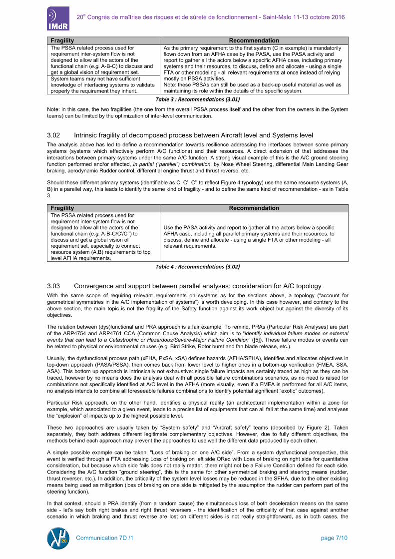
Fragility Recommendation The PSSA related process used for requirement inter-system flow is not designed to allow all the actors of the functional chain (e.g. A-B-C) to discuss and get a global vision of requirement set.
As the primary requirement to the first system (C in example) is mandatorily flown down from an AFHA case by the PASA, use the PASA activity and report to gather all the actors below a specific AFHA case, including primary systems and their resources, to discuss, define and allocate - using a single FTA or other modeling - all relevant requirements at once instead of relying mostly on PSSA activities. Note: these PSSAs can still be used as a back-up useful material as well as maintaining its role within the details of the specific system.
System teams may not have sufficient knowledge of interfacing systems to validate properly the requirement they inherit.
Table 3 : Recommendations (3.01)
Note: in this case, the two fragilities (the one from the overall PSSA process itself and the other from the owners in the System teams) can be limited by the optimization of inter-level communication.
3.02 Intrinsic fragility of decomposed process between Aircraft level and Systems level The analysis above has led to define a recommendation towards resilience addressing the interfaces between some primary systems (systems which effectively perform A/C functions) and their resources. A direct extension of that addresses the interactions between primary systems under the same A/C function. A strong visual example of this is the A/C ground steering function performed and/or affected, in partial (“parallel”) combination, by Nose Wheel Steering, differential Main Landing Gear braking, aerodynamic Rudder control, differential engine thrust and thrust reverse, etc.
Should these different primary systems (identifiable as C, C’, C’’ to reflect Figure 4 typology) use the same resource systems (A, B) in a parallel way, this leads to identify the same kind of fragility - and to define the same kind of recommendation - as in Table 3.
Fragility Recommendation The PSSA related process used for requirement inter-system flow is not designed to allow all the actors of the functional chain (e.g. A-B-C/C’/C’’) to discuss and get a global vision of requirement set, especially to connect resource system (A,B) requirements to top level AFHA requirements.
Use the PASA activity and report to gather all the actors below a specific AFHA case, including all parallel primary systems and their resources, to discuss, define and allocate - using a single FTA or other modeling - all relevant requirements.
Table 4 : Recommendations (3.02)
3.03 Convergence and support between parallel analyses: consideration for A/C topology With the same scope of requiring relevant requirements on systems as for the sections above, a topology (“account for geometrical symmetries in the A/C implementation of systems”) is worth developing. In this case however, and contrary to the above section, the main topic is not the fragility of the Safety function against its work object but against the diversity of its objectives.
The relation between (dys)functional and PRA approach is a fair example. To remind, PRAs (Particular Risk Analyses) are part of the ARP4754 and ARP4761 CCA (Common Cause Analysis) which aim is to “identify individual failure modes or external events that can lead to a Catastrophic or Hazardous/Severe-Major Failure Condition” ([5]). These failure modes or events can be related to physical or environmental causes (e.g. Bird Strike, Rotor burst and fan blade release, etc.).
Usually, the dysfunctional process path (xFHA, PxSA, xSA) defines hazards (AFHA/SFHA), identifies and allocates objectives in top-down approach (PASA/PSSA), then comes back from lower level to higher ones in a bottom-up verification (FMEA, SSA, ASA). This bottom up approach is intrinsically not exhaustive: single failure impacts are certainly traced as high as they can be traced, however by no means does the analysis deal with all possible failure combinations scenarios, as no need is raised for combinations not specifically identified at A/C level in the AFHA (more visually, even if a FMEA is performed for all A/C items, no analysis intends to combine all foreseeable failures combinations to identify potential significant “exotic” outcomes).
Particular Risk approach, on the other hand, identifies a physical reality (an architectural implementation within a zone for example, which associated to a given event, leads to a precise list of equipments that can all fail at the same time) and analyses the “explosion” of impacts up to the highest possible level.
These two approaches are usually taken by “System safety” and “Aircraft safety” teams (described by Figure 2). Taken separately, they both address different legitimate complementary objectives. However, due to fully different objectives, the methods behind each approach may prevent the approaches to use well the different data produced by each other.
A simple possible example can be taken; "Loss of braking on one A/C side”. From a system dysfunctional perspective, this event is verified through a FTA addressing Loss of braking on left side ORed with Loss of braking on right side for quantitative consideration, but because which side fails does not really matter, there might not be a Failure Condition defined for each side. Considering the A/C function “ground steering”, this is the same for other symmetrical braking and steering means (rudder, thrust reverser, etc.). In addition, the criticality of the system level losses may be reduced in the SFHA, due to the other existing means being used as mitigation (loss of braking on one side is mitigated by the assumption the rudder can perform part of the steering function).
In that context, should a PRA identify (from a random cause) the simultaneous loss of both deceleration means on the same side - let’s say both right brakes and right thrust reversers - the identification of the criticality of that case against another scenario in which braking and thrust reverse are lost on different sides is not really straightforward, as in both cases, the
Communication 7D /1 page 7/10

20e Congrès de maîtrise des risques et de sûreté de fonctionnement - Saint-Malo 11-13 octobre 2016
outcome is always Loss of braking on one side combined with Loss of reverse thrust on one side. As a result, a new criticality validation activity has to be required and performed, delaying the PRA result if not anticipated beforehand. The non-anticipation of that kind of case is identified as fragility of the Safety function against the threat associated to the inclusion of the PRA objective and the bottom-up process within an overall “top-down” failure scenario modeling.
Thinking of the high complexity and usual asymmetry of aircraft network implementations (EWIS and pipe positions, data mapping to different wires and network nodes, asymmetry of threat sources, timing asymmetry of control units, etc.), the conclusion of importance of account for A/C topology towards PRA impact assessment correctness and completeness is identified, as well as the significance of the associated fragility.
This leads to the following recommendation.
Fragility Recommendation The design of FHA-xSA dysfunctional process is not optimized to support “multi-failure bottom-up” process (used especially by PRAs) in terms of account for A/C topology and implementation.
Account for the expected A/C topology (right/left; forward/aft.) of system implementations from the FHA Failure Condition level in order to anticipate potential PRA needs.
Table 5 : Recommendations (3.03)
Note: it can be argued that separation and independence of PRA and FHA/xSA activities contributes to the overall Safety function coverage. To this it is answered that this recommendation does not lead the dysfunctional approach to modify the PRA process itself, but only to provide more adapted usable data.
3.04 Priority management and anticipation aspects In supplement to the technical process-oriented sections above, this section closes section 3 by discussing organizational topics identified to be relevant throughout all the aspects of the Safety function activities, related to specific function objective #3 from section 2.01 and considered interesting.
In the context of its inclusion within a complex frame of different other functions, the Safety function efficiency against its own objectives can be threatened by requests for support activity. In that, its resilience can be measured by its ability to absorb these external loads - not necessarily anticipated by other functions - without being prevented or delayed in the achievement of its own objectives. This challenge associated with the status of “support” function carried by Safety, which is also the main point of involvement of the function management, is the object of this section.
As a reminder, support requirements - besides the issuance of safety analyses themselves which may be constrained by Airworthiness function planning - can cover a broad list of subjects such as MMEL, maintenance errors analysis, flight tests and associated problem solving, AFM design, ARP4754 (among others listed below Table 2), each of them showing a high level of priority during critical phases. Additionally, the safety process itself shows a high level of overlapping activities, roughly LRU level FMEAs feeding system level FMEA, itself an output to FTAs which then have to be validated by CMAs, for example.
Two paths are proposed to enhance Safety function resilience against unexpected workload related problems: the ability to anticipate these workloads and the ability to momentarily decrease the workload on Safety primary tasks. These paths are applicable both at airframer and system supplier levels.
Anticipation of the external workload includes the following management-oriented proposals, aiming to restrict the time passed out of primary Safety related activities by increasing efficiency on side tasks:
First, to have a complete knowledge of all external activities in which Safety focals are to be involved in. As already listed, this includes understanding other activities that Safety may require input data from (and have to review and validate: SFHA Failure Conditions criticalities validation activities from other specialties are an example) or deliver some data to (and so constraint: LRU criticality definition out of [1], [2] requirements 1316 & 1317 regarding HIRF and Lightning is an example).
To produce a complete list of activities and provide it to focals so they can anticipate the potential requirements they might have at their own level. It has to be noted that because of certification program scarcity and potential use of young engineers and/or contractors, focals cannot all have enough experience of aircraft certification to identify which tasks are time demanding and / or expected. Therefore, give the teams the sense of what is required - by listing tasks and describing the processes, or periodically provide anticipated activities technical presentations - is considered an important first step to be able to manage top-level activity planning.
To define side activity processes ahead of their performance, which is obvious, but also include practical constraints as soon as possible in such processes: how the requirements will be transmitted, under which format, and the data needed to timely answer to the request are some subjects to be tackled. Because the management cannot have an accurate view of practical issues that may arise when answering to the requirement, focals should be involved in that kind of discussion - creating a “subject task force” is potentially the best way to proceed.
It can be noted that at airframer level, this activity may include to define some data delivery requirements to suppliers, which leads to specific management issues.
In a general way, to define technical process rules to deal with a specific subject. As an example, an activity such as a derived requirements review cannot be initiated without having defined the rules to apply to define a requirement as safety related - otherwise the identification of safety derived requirements may show a fair deal of inconsistency between different focals along with delaying the focals in performing the activity itself.
Now considering that a focal has to switch momentarily out of his safety analysis to another subject, the following proposals are suggested, which can prevent that switch from impacting the timeframe of that safety analysis too much:
Communication 7D /1 page 8/10

20e Congrès de maîtrise des risques et de sûreté de fonctionnement - Saint-Malo 11-13 octobre 2016
A double-system double-focal team (e.g. having two focals on both Braking System and Landing Gear System insteadof one focal on Braking System and another on Landing Gear System) is an asset to limit ramp-up time following anactivity transfer.
To make this transfer easy, and also allow an easier “ramp-back-up” of the focal once the activity is finished, it isrecommended to gather all relevant information, data and open points list at the same location. An ideal one can be thedraft report of the (P)SSA/PRA/ASA itself because, as the final report to be provided considering the stage of theprogram, this report identifies the process and gathers the results in terms of data: should these results not be there, the“hole” is directly identified and a task can be associated.
To support that, it is recommended to initiate reports in the final (certification) form and structure as soon as possible, toinitiate the mind’s orientation towards that objective.
Finally, and without originality, this recommendation addresses the classification of each activity's tasks per priority orcriticality: the more critical the task is, the more accurate the activity transfer needs to be. The main point here is toanticipate focal unavailability and continuously identify which tasks are critical among the activities he performs andshare that critical knowledge with the other focal(s) of the team. Depending on task criticality, the knowledge to beshared may cover, in increasing order of criticality: the what (this task is being done), the how (this task is being done,like this) and then the why (this task is being done like this, because of that context, so don’t try doing otherwise).
Note: experience shows that the most critical tasks are often the ones that involve communication with externalsuppliers in order to obtain input data, as they give room to misinterpretation, difficulty to manage delay, quality issues,and many other causes of delay. It is therefore recommended to prioritize such activities over ones performed internally.
Another possible lever to allow the focal to move to another activity scope without losing much time is to initiate asupplier activity that will run during his absence, by sending all requirements and inputs before leaving. This implies tobe able to transfer requirements and data quickly to suppliers (ECM is the most flexible tools to do so), and implies alsoto be able to get supplier performing good quality work under minimal supervision.
The previous point allows to highlight a last remark in this communication, which is the necessity for each technical focalto have trustful relationships with his supplier counterpart; this sounds obvious but can be challenging considering thecomplexity of the tasks, the cultural diversity of the different stakeholders (anyone having led a meeting involving peoplewith more than 30 years of experience range, five different nationalities and more than 15 hours of time range willunderstand) and the potential existing tensions between organizations induced by that kind of ambitious context.
3.05 Conclusion Recommendations from Table 3, Table 4 and Table 5, not really obvious from an effort-management point of view, but supported by other recommendations from last section 3.04, show to be very specific and are identified as relevant to optimizethe efficiency of the Safety function by enhancing its resilience to issues caused by its own complexity as well as by external factors. Therefore, they validate the fact that the approach described in section 1 and proposed by this communication can be relevant and produce interesting results.
Communication 7D /1 page 9/10

20e Congrès de maîtrise des risques et de sûreté de fonctionnement - Saint-Malo 11-13 octobre 2016
Conclusion As stated in the introduction of this communication, full resilience analysis of the Safety function cannot be achieved easily: all the points left aside in this paper assess this lack of exhaustivity. The activity described in this communication has nevertheless reached two conclusions. The first one is that proposed approach is applicable and relevant for the analysis of a complex organizational function such as an Aircraft development Safety function. Applicability and potential to reach significant results are showed respectively in sections 2 and 3 and some further development of topics not developed here might lead to extend the list of recommendations towards resilience - and efficiency - enhancement.
The second conclusion lies on the identified results themselves. Today’s Safety process can be considered huge, both in terms of workload, scope and timeframe, which may prevent the individuals applying it to get enough global picture to identify properly process fragilities. The fact that this resilience analysis has identified - quite directly - some of these fragilities must remind the Safety function actors be vigilant and question further the implication of their results and how they reach them, in order to prevent process mistakes that may indirectly impact the function’s overall objectives. The authors will try to expand the identification of such possibilities of mistakes in their activities to come.
References [1] Code of Federal Regulation Title 14 Part 25 (14CFR25) - Airworthiness Standards: Transport Category Airplanes, US
Federal Aviation Authorities [2] Certification Specifications and Acceptable Means of Compliance for Large Aeroplanes (CS25), European Aviation Safety
Agency [3] Airframer.com, CSeries major suppliers list,
http://www.airframer.com/aircraft_detail.html?model=CSeries [4] F.Deschamps, 2016, Optimisation d'architectures de systèmes aéronautiques certifiables basée sur l'approche modèle,
Lambda-Mu 20 [5] ARP4754, Guidelines for Development of Civil Aircraft and Systems, Revision A, SAE Aerospace group [6] ARP4761, Guidelines and Methods for conducting the Safety Assessment process on civil airborne systems and equipment,
Revision --, SAE Aerospace group [7] FAA Aviation Maintenance Technician Handbook, FAA-H-8083-31, Ch.12 - Airframe Hydraulic and Pneumatic Power
Systems, and Ch.13 Aircraft Landing Gear Systems (http://www.faa.gov/regulations_policies/handbooks_manuals/aircraft/amt_airframe_handbook )
Acronyms A/C: Aircraft; ACMP: Alternate Current Motor Pump; AFHA: Aircraft Functional Hazard Analysis; AFM: Aircraft Flight Manual; APR (fr): Analyse Préliminaire des Risques (= FHA); ARP: Aerospace Recommended Practices; ASA: Aircraft Safety Assessment; CCMR: Candidate Certification Maintenance Interval; CMA: Common Mode Analysis; ECM: Engineering Coordination Memo; e.g.: exempli gratia; EICAS: Engine Indicating and Crew Alerting System; EIS: Entry Into Service; ETOPS: Extended-range Twin engine Operation Performance Standards; FA: Functional Analysis; FDAL: Functional Development Assurance Level; FHA: Functional Hazard Analysis; FTA: Fault Tree Analysis; HIRF: High Intensity Radiated Fields; IDAL: Item Development Assurance Level; IMA: Integrated Modular Avionics; I/O: Input/Output; LRU: Line Replaceable Unit; MMEL: Master Minimum Equipment List; PASA: Preliminary Aircraft Safety Analysis; PDR: Preliminary Design Review; PRA: Particular Risk Analysis; PSSA: Preliminary System Safety Analysis; RMAS: Reliability, Maintainability, Availability & Safety; SFHA: System Functional Hazard Analysis; SSA: System Safety Assessment; TLF: Top Level Failures; vs: versus; V&V: Validation & Verification.
Communication 7D /1 page 10/10