Embed Size (px)
Citation preview

© Fraunhofer IKTS
1
OMICS Group International is an amalgamation of Open Access publications and worldwide international science conferences and events. Established in the year 2007 with the sole aim of making the information on Sciences and technology ‘Open Access’, OMICS Group publishes 400 online open access scholarly journals in all aspects of Science, Engineering, Management and Technology journals. OMICS Group has been instrumental in taking the knowledge on Science & technology to the doorsteps of ordinary men and women. Research Scholars, Students, Libraries, Educational Institutions, Research centers and the industry are main stakeholders that benefitted greatly from this knowledge dissemination. OMICS Group also organizes 300 International conferences annually across the globe, where knowledge transfer takes place through debates, round table discussions, poster presentations, workshops, symposia and exhibitions.
About OMICS Group

© Fraunhofer IKTS
2
OMICS Group International is a pioneer and leading science event organizer, which publishes around 400 open access journals and conducts over 300 Medical, Clinical, Engineering, Life Sciences, Pharma scientific conferences all over the globe annually with the support of more than 1000 scientific associations and 30,000 editorial board members and 3.5 million followers to its credit.
OMICS Group has organized 500 conferences, workshops and national symposiums across the major cities including San Francisco, Las Vegas, San Antonio, Omaha, Orlando, Raleigh, Santa Clara, Chicago, Philadelphia, Baltimore, United Kingdom, Valencia, Dubai, Beijing, Hyderabad, Bengaluru and Mumbai.
About OMICS Group Conferences

© Fraunhofer IKTS
3
{
Ceramics for combustion
engines and turbines
Energy Harvesting
(Piezoceramics, TEG)
Fuel Cells
Photovoltaics Storage Technology
Membranes for Filtration
Oxyfuel / Power to Gas
Li-Battery
Supercup
Na-NiCl
SOEC -
(Electrolysis
)
Smart advanced ceramic materials for energy and environmental technology
Alexander Michaelis, Fraunhofer IKTS
© Fraunhofer IKTS
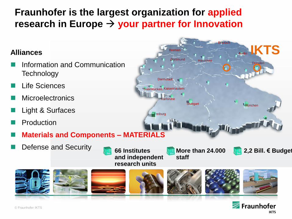
66 Institutes and independent research units
More than 24.000 staff
2,2 Bill. € Budget
Dortmund
Darmstadt
Dresden
Bremen
Hannover
Karlsruhe
Saarbrücken
München Stuttgart
Berlin
Rostock
Freiburg
Kaiserslautern
Alliances
Information and Communication
Technology
Life Sciences
Microelectronics
Light & Surfaces
Production
Materials and Components – MATERIALS
Defense and Security
IKTS
Fraunhofer is the largest organization for applied
research in Europe your partner for Innovation

© Fraunhofer
5
Fraunhofer worldwide
Subsidiary Center
Representative Office
Dubai
Bangalore
Jakarta
Beijing Seoul
Tokyo
Boston Plymouth
East
Lansing San José Newark
Maryland
Cairo
Selangor
Senior Advisor
Project Center / Strategic Cooperation
Santiago de Chile
Singapore
Cambridg
e
Brussel
s
Porto
Vienna
Bolzano Gra
z
Paris Budapest
Wrocław
Gothenburg
Thessaloniki
Sydney

© Fraunhofer
6
Fraunhofer Institute of Ceramic Technologies and Systems: IKTS
Mio € IKTS MD
NDE IKTS HD Staff: 650

© Fraunhofer
7
Structural ceramics
Functional ceramics
Sintering / Materials -
Diagnostics and NDE (non
destructive evaluation)
Energy
systems and
life science
Materials
Processes and
Components
Environmental
Engineering Electronics / Smart
Microsystems
Industry 4.0 Additive Manufacturing
Smart advanced ceramic materials energy and environmental technology
Alexander Michaelis Fraunhofer Institute of Ceramic Technologies and Systems IKTS
TEG
© Fraunhofer
8
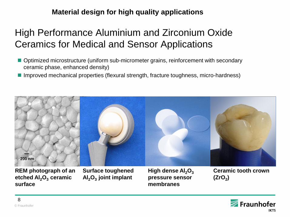
High Performance Aluminium and Zirconium Oxide
Ceramics for Medical and Sensor Applications
Optimized microstructure (uniform sub-micrometer grains, reinforcement with secondary
ceramic phase, enhanced density)
Improved mechanical properties (flexural strength, fracture toughness, micro-hardness)
REM photograph of an
etched Al2O3 ceramic
surface
Surface toughened
Al2O3 joint implant
High dense Al2O3
pressure sensor
membranes
Ceramic tooth crown
(ZrO2)
200 nm
Material design for high quality applications

© Fraunhofer
Veranstaltung
Vortragstitel Ort, Datum
9
Reaching physical limits
IKTS-Mosaik-window
81 ceramic-tiles

© Fraunhofer
Example (by IKTS): Real in-line transmission ~83%
(at 4 mm thickness)
Discs in photos: 4 mm thick, 0.6 µm grain size, hardness
HV10 ~ 14.5 GPa
Fraunhofer IKTS
Polycrystalline Ceramic
Very hard (equivalent to sapphire) scratch resistant
Excellent in-line transparency (at any thickness, any background)
(A. Krell et al., Int. J.
Appl.
Ceram.
Technol.
2011,
1108-1114; Opt.
Mater. 2014,
61-74)
ceramic: scratchproof as sapphire, but not as prone to cracks
Source: Future Technologies
Shen Ye

© Fraunhofer
IKTS sintered transparent ceramics outperforms sapphire !!
ceramics can be manufactured near-net-shape
Minimum finishing (grinding, cutting) effort
IKTS is world leading in optical / mechanical quality (own IP)
cost advantage
© Fraunhofer
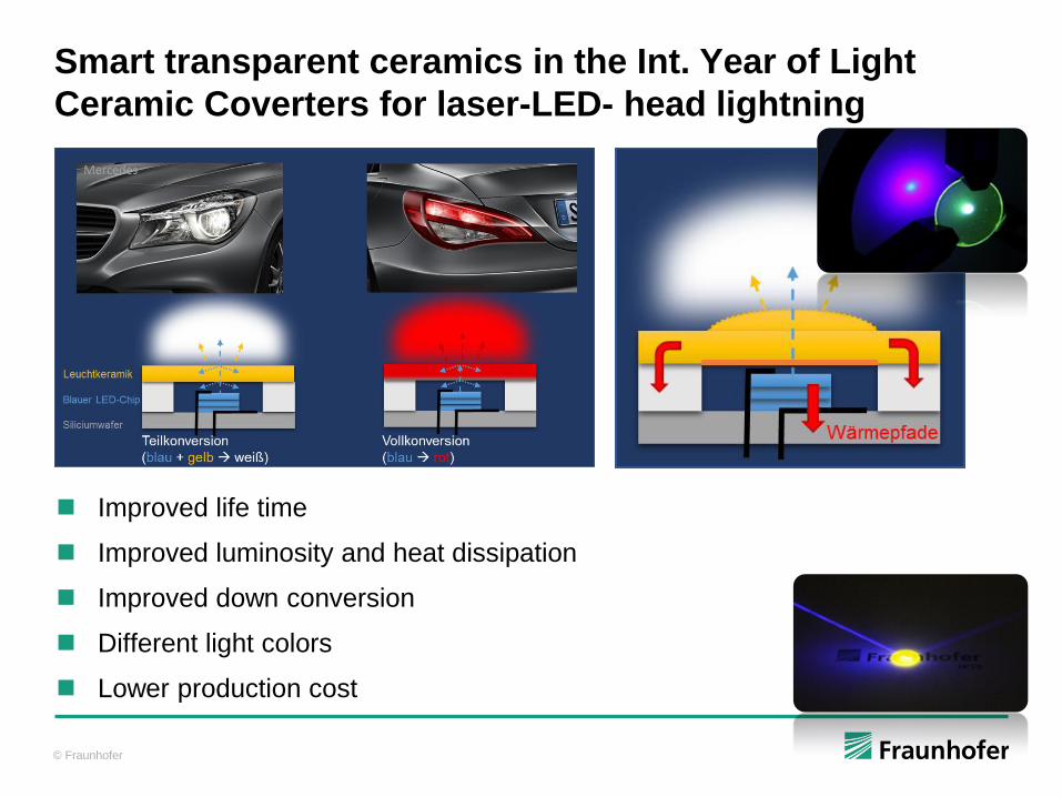
Improved life time
Improved luminosity and heat dissipation
Improved down conversion
Different light colors
Lower production cost
Smart transparent ceramics in the Int. Year of Light
Ceramic Coverters for laser-LED- head lightning

© Fraunhofer IKTS
13
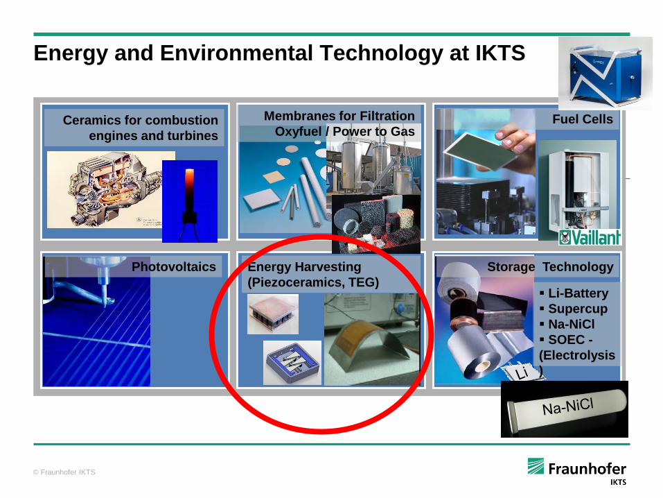
{ Energy and Environmental Technology at IKTS
Ceramics for combustion
engines and turbines
Energy Harvesting
(Piezoceramics, TEG)
Fuel Cells
Photovoltaics Storage Technology
Membranes for Filtration
Oxyfuel / Power to Gas
Li-Battery
Supercup
Na-NiCl
SOEC -
(Electrolysis
)

© Fraunhofer IKTS 14 WAC Forum 2012 / Perugia
Ceramic Membranes Supercaps Ceramic Foams
Design of pores in inorganic membranes for efficient
separation of liquids and gases
Dense Membranes

© Fraunhofer Slide 15/28
39th ICACC, 25-30 Jan 2015, Daytona Beach, Florida
Membrane thickness as thick
as necessary to avoid defects and
to get mechanical strength
Membrane thickness as thin
as possible to get high flux (m3/(m2h)
or (m3/(m2hbar)
Small pore size (micropores < 2 nm)
to separate on a molecular level
Narrow pore size distribution
to get high retention
as well as selectivity
Membrane
Intermediate layers
Support
Requirements for high performance membranes

© Fraunhofer IKTS 16 WAC Forum 2012 / Perugia
Colloidal oxide particles
Particle size: 5-10nm
Nanocrystalline after sintering
Pores between particles (crystals)
Pore size: 3-5nm
Ti + H 2 O Ti-O-Ti
O C 3 H 7
H 7 C 3 O O C 3 H 7
O C 3 H 7
H O O H
H O
H O
O H
O H
o o
- C 3 H 7 OH
Intermediate layer by colloidal sol-gel technique
Amorphous oxide membranes

© Fraunhofer Slide 17/28
39th ICACC, 25-30 Jan 2015, Daytona Beach, Florida
Amorphous oxide membranes
n Ti + 2nH2O Ti-O-Ti
OC3H7
H7C3OOC3H7
OC3H7 OC3H7
OC3H7
O
H7C3O
H7C3O-2n C3H7OH
(H+)
Mixture of Ti(i-OPr)4 and Zr(n-OPr)4
Longchain polymers
Structural pores („free volume“)
Pore size: < 1nm
Important: clean room conditions and humidity control
n/2
Polymer sol-gel technique
S. Zeidler, P. Puhlfürß, U. Kätzel, I. Voigt, J. Membr. Sci. 470 (2014) 421-430

© Fraunhofer Slide 18/28
39th ICACC, 25-30 Jan 2015, Daytona Beach, Florida
W & Au
Amorphous oxide membranes
100 nm
Material: amorphous TiO2(ZrO2)
Molecular weight cut-off MWCO:
a) 450 g/mol or b) 200 g/mol
Water flux: a) 20 l/(m2·h·bar)
b) 9 l/(m2·h·bar)
Membrane thickness: 50 nm
Pore size: a) 0.9 nm, b) 0.8nm
Open porosity: 30 %
Temperature stability: 350 °C
Pressure stability: 60 bar
High chemical stability
(2 mol/l HCl, 4 mol/l NaOH)
I. Voigt et al., 12th ICIM, 09-13 July 2012, Enschede, The Netherlands
Nanofiltration membranes

© Fraunhofer
Coloration Washing
Remaining
color bath
Colored
textile waste
water
Colored
cloth Gray cloth
Color bath Fresh water
COD: 60…6600 mg/l
pH: 3…12
Temp.: 20…90°C
Hydrogen peroxyde!
Amorphous oxide membranes
Waste water from textile industry

© Fraunhofer
Cathodic
reduction
Colorless
waste water
Coloration Washing
Remaining
color bath
Colored
cloth Gray cloth
Color bath Fresh water
Nanofiltration
Concentrate
Permeate Colored
textile waste
water
COD: 60…6600 mg/l
pH: 3…12
Temp.: 20…90°C
Hydrogen peroxyde!
Amorphous oxide membranes
Waste water from textile industry

© Fraunhofer Slide 21/28
39th ICACC, 25-30 Jan 2015, Daytona Beach, Florida
Membrane replacement 2012
Operating life: 10 years!
Commission: May 2002
Operation mode: feed & bleed
Concentration factor: 10...20
Membrane area: 25 m2
TMP: 15 bar
Cross flow velocity: 5 m/s
Permeate flux: 5 m3/h (200 l/(m2·h))
Amorphous oxide membranes
Waste water from textile industry

© Fraunhofer Slide 22/28
39th ICACC, 25-30 Jan 2015, Daytona Beach, Florida
Challenges: ingredients of „produced water“
Particles (abrasion)
Oil and tar (high fouling)
Salts (high scaling)
Ceramic membranes
Separation of oil droplets by microfiltration
Partial desalination by nanofiltration
Both together with one step nanofiltration
Amorphous oxide membranes
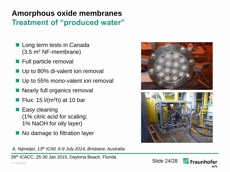
Treatment of “produced water”
“Produced water”: byproduct in oil and gas industry
(water flooding of oil reservoirs to increase yield, oil sand refinery, fracking)

© Fraunhofer Slide 23/28
39th ICACC, 25-30 Jan 2015, Daytona Beach, Florida
FEED PERMEATE RETENTATE
Amorphous oxide membranes
Treatment of “produced water”
Water treatment from oil sand refinery (Shell, Canada)
A. Nijmeijer, 13th ICIM, 6-9 July 2014, Brisbane, Australia
© Fraunhofer Slide 24/28
39th ICACC, 25-30 Jan 2015, Daytona Beach, Florida
Long term tests in Canada
(3.5 m2 NF-membrane)
Full particle removal
Up to 80% di-valent ion removal
Up to 55% mono-valent ion removal
Nearly full organics removal
Flux: 15 l/(m2h) at 10 bar
Easy cleaning
(1% citric acid for scaling;
1% NaOH for oily layer)
No damage to filtration layer
A. Nijmeijer, 13th ICIM, 6-9 July 2014, Brisbane, Australia
Amorphous oxide membranes
Treatment of “produced water”

© Fraunhofer IKTS
The American Ceramic Society`s 2015 Corporation
Environmental Achievement Award
Ceramic nanofiltration membranes for efficient water
treatment
Winners of the last years: Murata Electronics, Toyota Central Research,
OSRAM SYLVANIA Products, Pilkington Technology Management
Limited, SCHOTT North America
100 nm

© Fraunhofer
26
Environmental and Process Engineering
Ceramic Membrane Materials
Amorphous
Ceramic
Membranes
Carbon
MIECs
Zeolites Me
O-R
R-O
R-O
Me
O-R
O-R R-O
O Me
O-R
R-O
R-O
Me
O-R
O-R R-O
O
Structure of ceramic
membranes

© Fraunhofer
27
Environmental and Process Engineering
Amorphous
Carbon
MIECs
Zeolites
Examples of Application
Ceramic
Membranes
Wast water
cleaning
Bioethanol
dewatering
Biogas
purification
Oxygen separation

© Fraunhofer
28
Environmental and Process Engineering
Amorphous
Carbon
MIECs
Zeolites
Examples of Application
Ceramic
Membranes
Wast water
cleaning
Bioethanol
dewatering
Biogas
purification
Oxygen separation

© Fraunhofer IKTS
29
{ Energy and Environmental Technology at IKTS
Ceramics for combustion
engines and turbines
Energy Harvesting
(Piezoceramics, TEG)
Fuel Cells
Photovoltaics Storage Technology
Membranes for Filtration
Oxyfuel / Power to Gas
Li-Battery
Supercup
Na-NiCl
SOEC -
(Electrolysis
)

© Fraunhofer
AFC
80 °C PEM
80 °C
PAFC
200 °C
MCFC
650 °C
SOFC
850 °C
O2 O2 H2O O2 H2O CO2 O2 O2 Luft exhaust
current
load
Oxidation-
gas
Cathode
Electrolyte
Anode
Fuelgas exhaust
H2 H2O H2 H2 H2 H2O H2O H2
CO CO CO2 CO2
Alkaline
FC
Polymer
Electrolyte
Membrane
FC
phosphoric
acid FC
Molten
carbonate
FC
Solid
electrolyte
FC
OH-
H+ H+
CO3-
- O-
-
Multiple Fuel capable.
Simple Reforming = conventional
Hydrocarbon fuels can be used no Pt !
MCFC +
SOFC
optimum
systems for
CCHP
Fuel Cell Types MCFC: > 250 kW
SOFC: < 250 kW

© Fraunhofer
Material
MEA
System
Smart Ceramcs for Solid Oxide Fuel Cells (SOFC) at IKTS
3YSZ matrix LSC catalyst
Stack

© Fraunhofer eneramicby Fraunhofer
â
IKTS Fuel Cell System Competence
hydrogen
Ethanol
PEFC
Propane
Tubular
SOFC
LPG
Ethanol
SOFC
NG
SOFC
Biogas + NG
SOFC
Elektrolyse
Biogas + NG
MCFC
1 W 10 W 10 kW 1 MW 100 W 1 kW
portable portable portable stationary stationary

© Fraunhofer IKTS
- 33 -
Demonstration / Fieldtest
HotBox Core Module
100 Wel, LPG-fueled Portable Power Generator
Heatexchanger
SOFC stack
Start-
burner
CPOx
Reformer
Burner
Systemintegration
eneramicby Fraunhofer
â

© Fraunhofer IKTS
- 34 -
Lifetime Test (ongoing) Hotbox Testing incl. Reformer / HEX

© Fraunhofer IKTS
- 35 -
Cycleability Hotbox Containing all Hot Components

© Fraunhofer IKTS
- 36 -
simple
add-up
Mikro-CHP for base load power
supply in single family homes
Typical 24/7 power demand in
single family home

© Fraunhofer IKTS
37
MCFC: Market proven!
300MW Fuel Cell power in operatoion
Maritime applications
More than 80 Direct FuelCell® plants are running in the field

© Fraunhofer IKTS 38
Structure of ceramic
membranes
Morphology of Carbonate Fuel Cell
Membrane
Intermediate
layers
Substrate
(Support)
Anode,
a
Electrolyte,
e
Cathode,
c
Design of the cell active components ensures that:
Matrix pores are filled with electrolyte (via capillary force)
during entire operation
Large pores in anode and cathode (gas-diffusion electrodes)
remain unfilled with electrolyte

© Fraunhofer IKTS
39

© 2012-14 FuelCell Energy Solutions GmbH 40 December 2014
Versatile Applications
Heat
Ultra-clean
Electricity
Tri-generation DFC-H2 Hydrogen Fueling Station/Pipeline
Hydrogen
Carbon-Neutral Renewable Hydrogen
Renewable biogas from wastewater
treatment facility
Example: DFC 1500H: 1.1MWel – 0.44MWth – 635Kg H2/Day or alternatively 1.3MWel – 0.64MWth – 100Kg H2/Day - ratio can be adjusted in operation - H2 in 5*9 Quality

© Fraunhofer IKTS
41
{ Energy and Environmental Technology at IKTS
Ceramics for combustion
engines and turbines
Energy Harvesting
(Piezoceramics, TEG)
Fuel Cells
Photovoltaics Storage Technology
Membranes for Filtration
Oxyfuel / Power to Gas
Li-Battery
Supercup
Na-NiCl
SOEC -
(Electrolysis
)

© Fraunhofer
The Energy future – as we see it
Supercap Li-Ion NaNiCl Redox-Flow
SOEC
Power
to Gas (Fuel)
Solar MCFC
SOFC Solar Wind
residential commercial Small grid
6 .. 7
Grid
Base load Industry
Power generation
technology
Sca
le
SOFC
Range
extender
Sto
rag
e
tec
hn
olo
gy
Application
kWh TWh
Biogas
PtG
e-mobility
Conventional and
carbon based energy conversion
approaching real decentralized (no-grid) solutions

© Fraunhofer IKTS
Li-Ion Battery value chain
Material and
electrode
characterization
Sophisticated
spectro-
electrochemical
characterization
(impedance,
Raman,…)
Electrical and
thermal
characterization of
commercial cells
Stationary and
dynamic modeling
of battery cell
performance
Powder synthesis
and modification
Methods for
analysis and
optimization of
thermal process
Methods for
characterization of
powders (FESEM,
XRD; Raman;
thermal properties;
particle size )
Development of
an adapted slip
compositions for
the coating
process
Sophisticated
methods of slurry
characterization
and optimization
Efficient methods
for slurry mixing
Development of
technologies for
coating of
electrode films
Powder synthesis Slurry Mixing Electrode
manufacturing
Cell assembly &
packaging Cell testing

© Fraunhofer IKTS 44
Tap density
Capacity
Processing Discharge current
Cycle stabilty Power density
Life time Safety
Ceramic technology determines performance of batteries

© Fraunhofer
45
Efficient manufacturing methods for high-performance
lithium ion batteries: From Lab. to Fab.
Battery assembly Slurry mixing Electrode
manufacturing Cell testing
Cell assembly +
packaging
Development of optimized
manufacturing methods along the entire
value chain of lithium ion cell production
Pilot scale production of
Li-Ion-Batteries
TKSY IKTS

© Fraunhofer IKTS - 46 -
Example: Electromobility
BMW i3
150 km Reichweite
Tesla Model S
Ca. 500 km Reichweite
~ 8000 Zellen
je 3,4 Ah
96 Zellen
je 60 Ah

© Fraunhofer IKTS - 47 -
LiNi0,5Mn1,5O4/Li4Ti5O12 – Bipolar battery
VERTRAULICH

© Fraunhofer IKTS
48 - confidential -
Operation principle (Zebra)
NiCl2 + 2Na Ni + 2NaCl, E0 = 2,58 V
Electrolyte Na-ß“-aluminate (ceramics)
Cathode: Ni, common salt (NaCl), NiCl2, NaAlCl4
Anode: Na (melt)
Operation temperature: 270 – 350 °C
Na/NiCl2 solid state electrolyte batteries for stationary applications
+ -
Na
Na - ß“ - aluminate
electrode case
lid (Al2O3)
Na +
Ni NaCl
NaAlCl 4
NiCl 2

© Fraunhofer IKTS
49 - confidential -
Material costs: NaNiCl (long run marginal costs)
2004 2014
13 $
52 $ Ni-prize
2004 - 2014
source: Fiamm

© Fraunhofer IKTS
50
reduction of production cost by factor 10
Flat substrates
20 bis 30 mm,
thickness 0,5 to 2 mm
Beakers 20 mm,
wall thickness. 1,5 mm,
length 150 mm
Extrusion Dry pressing
Isostatic pressing
Tubes 20 bis 60 mm,
wall. 1,5 mm, legth up
to 600 mm
cost-
reduction:
factor 10

© Fraunhofer IKTS
51
Na-Battery Li-Battery
+ 50°C
- 30°C 300 °C
40 °C
DT = 250°C
DT = 330°C DT = 70°C
DT = -10°C
Cell cost : 100 € / kWh
System : 300 € / kWh
Inherently safe !
Marginal electronics / BMS
Radiation self cooling
Thermal insulation not dependent
on environment
cell: 300 € / kWh
System: 1200 € / kWh
Not safe (external efforts required)
BMS and Symmetrisierung
Active heating/cooling required
Life time depends on environment
Example: stationary battery / Na-Batterie vs. Li-
Batterie
cost-reduction: factor 10

© Fraunhofer
MATERIALS AND PROCESSES
MECHANICAL AND VEHICLE ENGINEERING
ELECTRONICS AND MICRO SYSTEMS
ENERGY MATERIAL- AND PROCESS ANALYSIS
OPTICS
BIO- AND MEDICAL TECHNOLOGIES
ENVIRONMENTAL ENGINEERING
Advanced Ceramics for product innovations at IKTS
NDE
© Fraunhofer
Backup
© Fraunhofer IKTS
Energy and Environmental Technology at IKTS
Ceramics for combustion
engines and turbines
Energy Harvesting
(Piezoceramics, TEG)
Fuel Cells
Photovoltaics Storage Technology
Membranes for Filtration
Oxyfuel / Power to Gas
Li-Battery
Supercup
Na-NiCl
SOEC -
(Electrolysis
)

© Fraunhofer
TEG: state of the art (thermoelectric converters)
Bi2Te3 200°C
ZT 0,8….1,5
SiGe
PbTe 400°C
Skutterudite (Co,Ni)Sb3

© Fraunhofer
some thermoelectric ceramic material
candidates
ZT
0,9
leve
l o
f s
em
ico
nd
uc
tive
TE
Ceramic thermoelectrics
(Zn
1-yM
gy) 1
-xA
l xO
, Tso
bo
ta 1
99
8
SrT
i 0,8N
b0,2
O3,
Le
e 2
00
7
ZT at 400°C
Sr 0
,9D
y0,1T
iO3,
Mu
ta 2
003
TiO
1,9
4, Tsu
yu
mo
to 2
006
Bi 2
Sr 2
Co
2O
x,
Fu
na
ha
shi 2000
B13C
2,
We
rhe
it 2
006
B13C
2,
We
rhe
it 2
006
at
1600°C

© Fraunhofer
Potential of ceramic thermoelectrics, TiOx
disadvantage advantage

© Fraunhofer
Titanium suboxide as a thermoelectric material
Why titanium suboxide?
Large quantities available
good chemical stability (except for oxidation)
Low costs compared to other thermoelectrics (< 20 €/kg, TiOx)

© Fraunhofer
Titanium suboxide as thermoelectric material
Thermoelectric potential of TiOx?
Calculations for single phase Magneli phases predict ZT < 0.2 confirmed
Nanostructure, mixed phases, composite (TiN,…) - effects ? ZT 0.5…1 ?
TE data found experimentally
Seebeck-
Coefficient
electrical
conductivity
thermal
conductivity
220
40
800
80
6
1
µV
/K
S·c
m
W/m
K
ZT range: 0.0016 … 2,3 reasonable ZT goal: 0.4 … 1.0
M. Backhaus-Ricoult, J.Electr.Mat. 41 (2012)
DOI:10.1007/s11664-012-2019-4
IKTS
figures

© Fraunhofer
Magnéli phases Ti4O7 and Ti8O15 and their carbon nanocomposites via the thermal decomposition-precursor route
•S. Conzea, , , I. Veremchukb, M. Reiboldc, B. Mattheya, A. Michaelisa, Yu. Grinb, I. Kinskia, Journal Solid State Chemistry 2015 (235)
0.0
1.0
2.0
3.0
4.0
5.0
6.0
0 200 400 600 800 1000
therm
al
co
nd
ucti
vit
y (
W/m
K)
temperature (°C)
TiO1,90precursor
TiO2 (He)
precursor derived Ti-O for micro-structure optimization
bench mark process
for lowest thermal conductivity

© Fraunhofer
Target process
material
processing
pressureless
sintering
manufacture
of TE-legs
manufacture
of modules
assembly
technologies
Cutting
Oxidation
protection
TEG module fabrication by established (low cost)
ceramic processing

Material development
Development of sintered TiOx by different technologies
Reached maximum ZT770 °C = 0,22
Upscaling of material production to ~ 100 kg TiOx
Assembley- and joining technology
Low cost SiN substrates
Oxidation protection for TiOx by glass coating
low contact resistance by active filler brazing
Metallization of substrates with Cu, Ni
.
Thermoelectric modules
successful development of uni-leg modules
Optimised process integration
use of industrial components
application testing ongoing
TiOx thermoelectrical generators

© Fraunhofer IKTS
ICC6 August 21–25, 2016 (Dresden, Germany)

© Fraunhofer
MATERIALS AND PROCESSES
MECHANICAL AND VEHICLE ENGINEERING
ELECTRONICS AND MICRO SYSTEMS
ENERGY MATERIAL- AND PROCESS ANALYSIS
OPTICS
BIO- AND MEDICAL TECHNOLOGIES
ENVIRONMENTAL ENGINEERING
Advanced Ceramics for product innovations at IKTS
NDE
© Fraunhofer IKTS
Backup

© 2012-14 FuelCell Energy Solutions GmbH 66 December 2014
Co-Production of Renewable Hydrogen in California
66
• Site load ~ 6 MW; up to 300 kW provided from fuel cell
• Engines on biogas reduced from 13 MW to <4 MW – due to NOx constraints
• Potential using biogas fuel cell: 20 MW + 20 MW of peak power and
kVAR support

© Fraunhofer IKTS
67 - confidential -
H2 Power to Gas
Power to Liquid
NaNiCl2 Batteries – Application range
CAES: Compressed Air Energy Storage
H2: Hydrogen (Electrolysis)
Min
ute
s
Se
co
nd
s
Ho
urs
D
ays
1 kW 10 kW 100 kW 1 MW 10 MW 100 MW 1.000 MW
Electrochemical Batteries
Redox-Flow-Batteries Pumped
Hydro
Time Shift /
Energy Management
Wind
Turbine
on-shore
Wind
off-shore
Medium
PV Farm
Residential
Power
Quality
Bridging
Power
Li-Ion
NaNiCl2
Lead Acid
VRB ZnBr
(Thermo-) Mechanical Storage
Electrochemical Storage
Chemical Storage
Commercial /
Infrastructure
Building
Community
Storage
Power to Heat
(to Power)
CAES

© Fraunhofer
Process optimisation
T= 300 K
1.5
k
W/mK
T= 300 K
2.5
k
sintering temperature 1300°C / SPS
sintering temperature 1300°C / pressureless sintering
Precursor route
powder route
no C contamination
low cost process ZT ~ 0.2
bench mark process for lowest thermal conductivity