Embed Size (px)
Citation preview
® Australian Railway Kits ABN: 27 416 246 418
Incorporating Main West Models
Manufacturers, Wholesalers and Retailers of Quality Australian Model Railways
PO Box 252 Warwick, Queensland, 4370 Australia
Phone/Fax: 617 4667 1351 Website: www.arkits.com Email: [email protected]
NSWGR C38 (Streamlined)
Locomotive and Tender Kit E201 Manufactured Exclusively for AR Kits by DJH Engineering from Patterns owned by AR Kits
PLEASE READ INSTRUCTIONS THOROUGHLY BEFORE COMMENCING ASSEMBLY
CONSTRUCTION
It is important to ensure that all parts are clean, free of "flash" (excess metal on castings) and fit properly. The "flash line" is easily removed
from most areas by scraping gently with a sharp hobby knife - a round blade is more effective than a straight pointed type. Pull the blade
along the "flash line" - several light strokes are better than a single one. Some areas are better cleaned up with 6" jewellers' files. Take care
not to flatten round parts by filing too heavily. All locating holes for detail fittings should be pre-drilled to the size specified in the
instructions. Sometimes it is necessary to clean out these holes with a "rat tail" file; take care not to snap off the tip of the file. Gently wash
the castings in warm soapy water to remove mould release residue.
Etched brass items are best removed from the fret by placing the fret on a scrap piece of hard timber (eg Pyneboard) and cutting the tabs with
a large Stanley knife '- cut the tab at the point furthest away from the part, then trim the tab off close to the part with a small pair of quality
side cutters. Hold small parts with a pair of flat nosed (not serrated jaws) pliers while cleaning up with jewellers' files. Be careful not to
distort the etchings; they are difficult to straighten if bent or twisted. Drill all required holes before assembly, noting the spigot sizes of the
fittings, because some holes will be difficult to drill after parts are assembled.
As with all classes of NSWGR locomotives, individual C38s varied in minor details from time to time in their life. Modellers are therefore
advised to check photographs of the particular locomotive they have chosen to model.
These kits are designed to give many years of operating pleasure. A little extra time taken during construction will ensure that your kit will do
this. It cannot be emphasised too strongly that the basis of a smoothly operating model is care when constructing the chassis and valve gear,
ie you must double check every step. Check that the axles turn freely in their bearings, check again with the coupling rods on, then again with
the connecting rods on, etc, etc.
Assembly methods
The two main construction methods are:
(a) Low melt solder - Low melt solder is an excellent medium for use with white metal kits. It is quick and easy providing a stronger joint
than can be achieved with glue. It has the added advantage of easily repairing minor casting flaws, and because of the relatively low
temperature, many parts can be held in the fingers while soldering. Brass to white metal joints can also be made by "tinning" the brass first
with normal solder. Low melt soldering requires the correct type of soldering iron (e.g. Dick Smith T2200). These irons have temperature
control, as low melt solder only requires between 70 degrees and 200 degrees Celsius. You must use special low melting point solder, such
as that available from AR Kits.
IT IS ADVISABLE NOT TO ATTEMPT TO SOLDER ANY CASTINGS WITH A STANDARD SOLDERING IRON
(b) Glue - Superglue and Plastibond are two types of glues suitable for use with this kit. Some modellers prefer to superglue major joints first
then "fillet" the joint with Plastibond. Small detail parts are best glued with Superglue. Glue is not recommended for those parts needing good
electrical contact, such as the tender bogies. Whichever method you choose, "dry fit" parts first to ensure a good fit.
Page 1
Electrical Pickup
The electrical system used on these kits is called "half live". Looking from the top facing forward the locomotive chassis collects current
from the live wheels on the right-hand side, shown as LS (live side) on the drawings. The tender is insulated from the locomotive and current
is collected from the wheels on the left-hand side of the tender.
Cleaning up/Painting
On completion, any areas which were soldered should be washed using a soft brush and methylated spirits. An excellent pressure pack flux
remover is also available from Dick Smith stores. Then wash thoroughly in warm soapy water. Rinse with clean water and allow to dry
thoroughly before applying a suitable self-etch primer.
Spare Parts
Spare parts are available on a replacement basis. Should any part be missing or damaged contact AR Kits for a replacement. Should you
have any problems with the Mashima motor please do not attempt to repair it yourself - return the motor to us. Mashima will not replace
motors which have been tampered with.
Should you have any queries or problems with construction please drop us a note and we will do our best to advise. Likewise we would be
pleased to hear any suggestions you may have for improving the kits or instructions.
General
The following drill sizes are required: 0.4mm, 0.5mm, 0.6mm, 0.7mm, 0.8mm, 0.9mm,l.Omm, l.lmm,l.2mm,1.4mm, 1.5mm, 1.6mm, 1.7mm,
1.8mm, 1.9mm, 2.Omm, 2.9mm and 3.7mm.
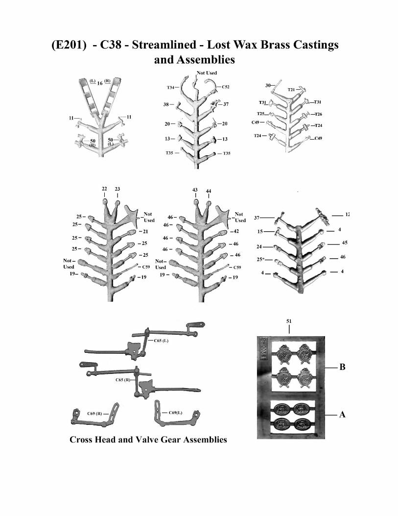
During construction refer to the drawings at all times. A number of parts are quite similar, so double check if in doubt. Note that attached to
the instructions is a photocopy of the lost wax brass castings sprues with each part numbered for easy identification. In the general
instructions the part numbers are shown in brackets.
The instructions sometimes refer to the right hand (R/H) and left hand (L/H) side. This is taken as viewing the model from above and looking
forward.
Where parts or assemblies are joined together, usually by wire or screws, often they cannot be shown close to each other on the drawing. In
such cases an asterisk (*) is used to identify the linking parts. For example, in Drawing 8 the single (*) shown against the expansion link
assembly (C69) denotes that this joins to the motion bracket (C37) which also has a single(*) against it. Similarly, the three(***) shown
against the slide bars (C46) denote that they join to the cylinders (C40) also shown with the asterisks (***).
Sometimes parts join to others which are shown on a different drawing. This is indicated by showing the linked drawing number in a circle.
For example, in Drawing 1 the holes in the tender base (Tl) link with the tender bolsters and bogies in Drawing 3: this is indicated by the 3 in
Drawing 1, and the 1 in Drawing 3.
To minimise the risk of losing parts, do not remove them from the etched fret or the plastic packing until you are ready to use them. We
recommend that you start construction with the tender.
Safety First
These models are not toys and are not suitable for young children. White metal castings contain lead and modellers are advised to
wash their hands after working with unpainted white metal castings. When using superglue, solder or when spray painting, ensure
your work area is well ventilated`
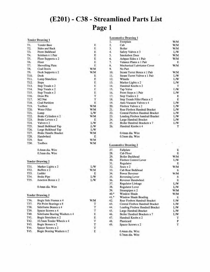
Tender Drawings T1, T2 & T3 (Parts Tl - T45)
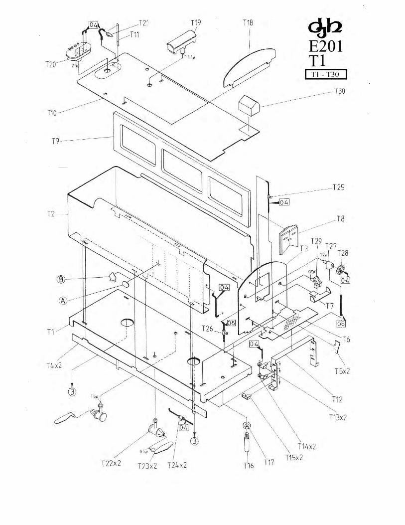
Take the tender base (Tl). At the front, fold the small side tabs down before folding the front down as shown on the drawing. At the rear of
the tender base fold the small side tabs down before folding the buffer beam down, then fold the coupler base so that the small tab locates in
the tender base. Take the tender back and sides (T2) and fold the bottom of the sides under as shown in the drawing before folding the three
small tabs on each side (these locate in the tender base). Now fold the tender back and sides (T2) to form rounded corners front and back,
note that the corners
Page 2
have a series of lines etched on the inside of the corners to facilitate rounded corners; fold the corners carefully to form a radiused corner,
not a sharp one. At this point solder the bogie centre pivots (T43x2) to the underside of the tender floor (Tl). Now fix the back and sides onto
the tender floor (Tl).
Fit the front bulkhead (T3) in position, then add sole bars (T4xpair) to the tender base (Tl) noting that they fix behind the small flaps at the
ends of the tender base - solder from inside the tender. Fix the floor (T6) to the front bulkhead (T3) followed by the floor supports (TSx2).
Fold and fit the shovelling plate (T7) note that the rear flap on the shovelling plate folds down to facilitate fitting. Before fitting the white
metal coal doors (T8), fit small bulkhead tap (T25) using 0.4mm wire, large bulkhead tap (T26) using O.5mm wire, brake handle bracket
(T27) using 0.5mm wire, hand wheel (T28) and seat (T29). Now fit the coal doors (T8).
Fold and fit the steps (T12) before adding step treads (T13x2), (T14x2) and (T15x2). Fit the drawbar pin (T16) using M2 nut (T17). Detail
the bottom of the tender fitting brake cylinders (T22x2), brake levers (T23x2) and valves (T24x2) using 0.4mm wire.
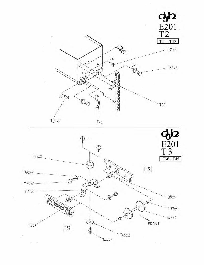
At the rear of the tender, fold and fit the grab handle (0.4mm wire) followed by the marker lights (T31x2), the junction boxes (T35x2), the
brake pipe (T34) and the buffers (T32x2). Fold and fit the ladder (T33) after the tender deck has been fitted.
Fit the deck supports (T9x2) to the inside face of the tender sides making sure that they locate on the tender base. Fix the coal partition (T18)
to the deck (T10), followed by lamp stanchion (T11) and lamp (T21) using 0.4mm wire, soldering from underneath the tender deck. Now test
fit the tender deck (T10) to the tender body from the rear of the tender, slipping it in between the tender sides. Check that it is a neat fit inside
the tender (and level) before fixing in place - we recommend a small amount of Superglue on the top of the deck supports to retain the deck
in place.
Using 0.4mm wire add two handles to the water filler (T20) before fixing the assembly to the tender deck. Test fit the toolbox (T30) - you
may need to file lightly for a neat fit, before fixing flush against the curve of the tender side. Fit toolbox (T19).
Fix the turned brass side frame mounts (T38x4) to the bogie side frames (T36x4). For good electrical pickup low melt solder is recommended
here. The bogie stretchers (T41x2) are on the etched nickel silver valve gear fret -remove them and check that the holes either side fit over the
brass side frame mounts (T38), you may need to enlarge the hole slightly. Fold the stretchers as per Drawing 3, using a pair of flat nosed
(non-serrated) pliers.
Push the brass wheel bearings (T37x8) in the bogie side frames using low melt solder if necessary, and attach the side frames to the stretcher
with brass spacer screws (T39x4) and washers (T40x4) also from the nickel silver fret.
Tighten the screws, then gently ease the side frames apart to fit the wheel sets (T42x4) in place, making sure the insulated wheels are on the
same side for each bogie - see drawing 1. Place the bogie on a piece of flat track and test run, some "fine tuning" may be necessary.
Take the bogie mounting screws (T4x2) and attach the assembled bogies to the tender (insulated wheels on the R/H side) using the washers
(T45x2).
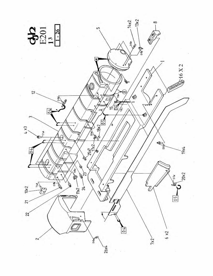
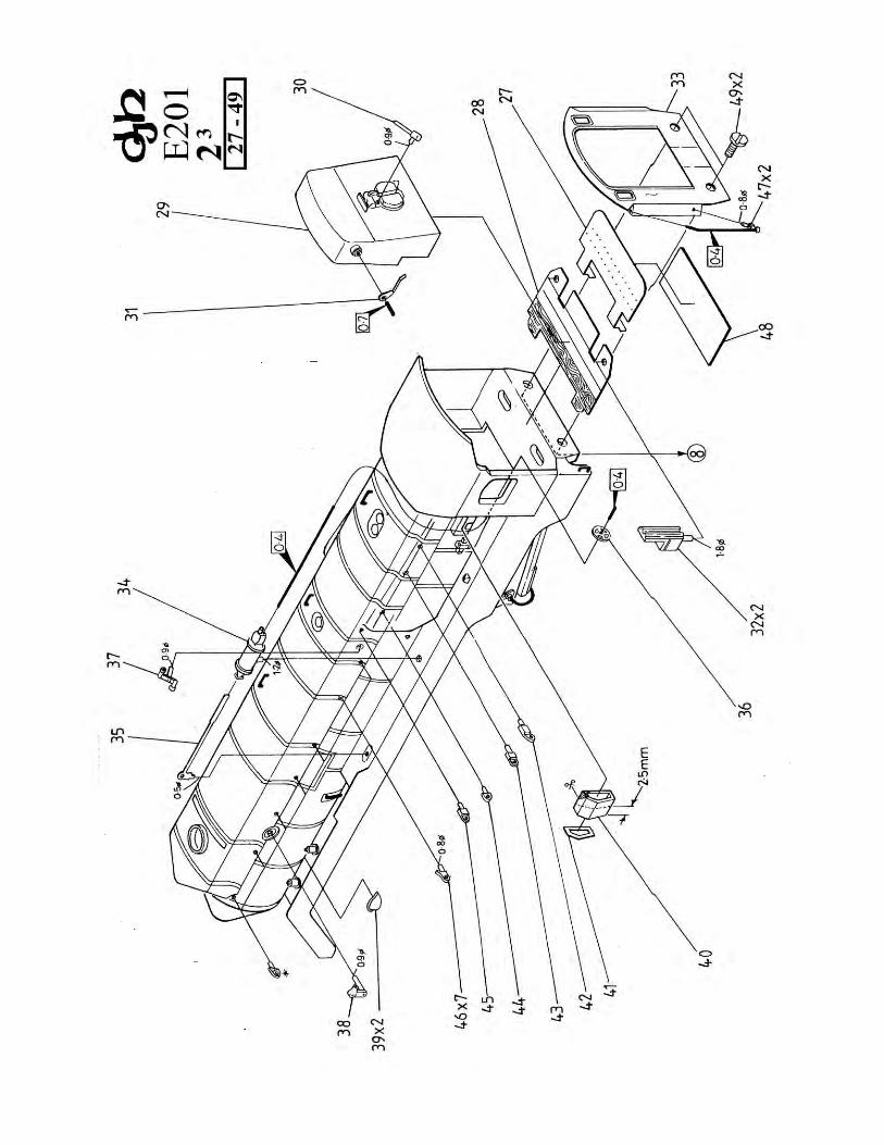
Locomotive Drawings 1 & 2 (Parts 1 - 49)
As mentioned previously all holes shown on the drawings should be drilled prior to assembly.
Clean up the footplate (1) and remove any feed sprues from the centre cutout under the boiler - take care not to remove the four valance
support lugs. Fix the smokebox/boiler/firebox (3) to the footplate (1) by low melt soldering inside the smokebox and at the bottom edge of
each side of the firebox.
Fit the cab (2) to the firebox (3). Fold the tabs on the rear of the valance plates (1lxpair) as shown. Using "standard" solder lightly "tin" the
back of the valance plates (7xpair) and fix to the footplate (1) using "low melt" solder, ensuring that they are level with the top of the
footplate.
Take the fall plate (27) and fold the tabs down 90 degrees, then glue the plasticard (48) to the underside, trimming it so that it overlaps the
three outside faces by 0.8mm to prevent it shorting out against the tender. Fit the tabs on the fall plate into the slots in the base of the cab, and
retain the fall plate in position by adding the cab floor (28). Detail the boiler back head (29), adding firebox control lever (30) and regulator
(31) using 0.7mm wire. Fit the back head assembly into the cab and fix in place. Trim the locating spigots on the bottom of the seats (32x2)
and fix to the cab floor (28). Take the cab rear bulkhead (33) and fold the sides as shown in Drawing 5, with the two "triangles" at the top of
the sides folded down slightly. Test fit the cab rear bulkhead to the back of the cab and adjust folds if necessary. Using "standard" solder,
lightly "tin" the top and bottom edges of the cab rear bulkhead. Position the cab rear bulkhead against the cab and join the two using "low
melt" solder. Fit the ash pan sides (6xpair) to the bottom of the footplate.
Fix the smokebox (5) door in place noting that the line on the top of the smokebox door (5) aligns with the point of the cowling. Add marker
lamps (13 x 2) to the smokebox door. Detail the locomotive body, adding the safety valves (4x3) steam turret boxes (10xpair), steam turret
valves (11 x pair), whistle (12) using 0.4mm wire and tap valve (15) using 0.4mm wire. Make up steps using step treads (17x2) and step tread
Page 3
fillet plates (18x2) and fit to the boiler. Using 0.5mm wire, fit the small pipes either side of the boiler between the footplate and boiler (just
behind the smokebox), before fitting the mechanical lubricator cover (8) to the L/H side of the footplate - you may need to make a small
cutout in it to clear the 0.5mm wire; note that the cover plate is aligned with the raised section on the top of the valance. Now fit the anti-
vacuum valves (19x4) followed by the firebox valves (20x2) using 0.5mm wire. Note that the front steps (16xpair) will be fitted later.
The detailing goes on... Add power reverser (34) and reversing lever (35). Solder reverser hand wheel (36) to a length of 0.4mm wire, and
pass the end of the wire through the cab front to locate in the power reverser (34). Add the regulator linkage (37), regulator lever (38), steam
pipes (39x2). If fitting the optional driver's window shade, trim the window shade (40) to a length of 2.5mm, add window shade beading (41)

and fix the assembly in place.
On the L/H side of the locomotive fit handrail brackets (42 through to 46x7) as shown in the drawing, and slip one handrail knob (14x2) onto
the handrail after shaping. The handrails should be added after the pipe work, as shown in Drawing 6 - refer to photographs for assistance
with pipe detailing. On the R/H side, because the handrail is continuous, you will find it easier to shape the handrail, then slip the handrail
brackets (21 through to 25x7) and one handrail knob (14x2) onto the wire before fitting the assembly to the body. Fit handrail knobs (26x4)
to the front of the cab and add 0.4mm wire. Add handrail knobs (47x2) to the cab rear bulkhead (33) and using 0.4mm wire, fit cab handrails
and grab handles as shown in Drawing 6.
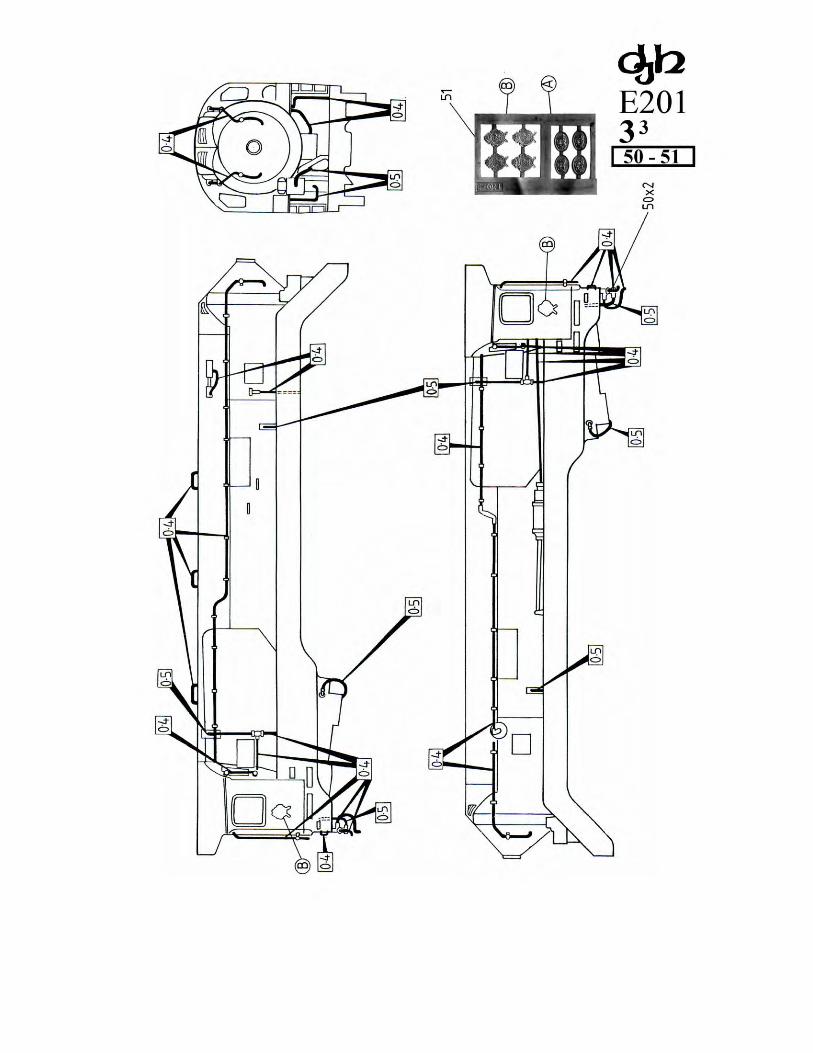
Locomotive Drawing 3 (Parts 50 - 51)
Fit the injectors (5O x pair) and add 0.5mm wire. Complete piping and handrails as shown in Drawing 6. The etched fret containing the
builder's plates (51) has the Clyde builder's plates at the top (B in Drawing 6) for the streamlined locomotives (and tenders) 3801- 3805. The
bottom oval plates (A in Drawing 6) are for the standard locomotives (and tenders) 3806 - 3830.
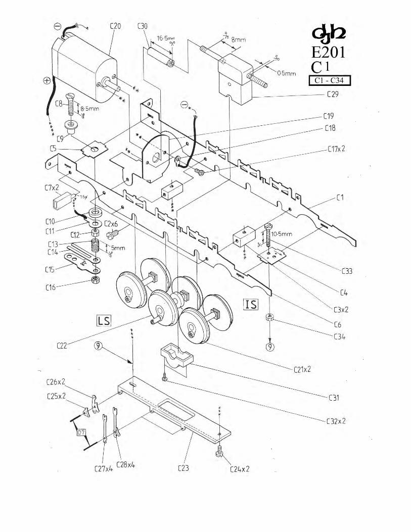
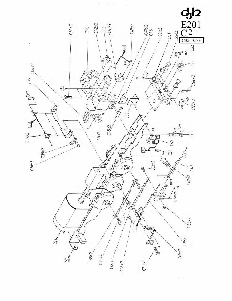
Locomotive Drawings C1 & C2 (Parts Cl - C73)
Take the L/H frame (C l) and R/H frame (C6) and fold the rear tabs as shown in the drawing. Secure the two frames together using the
spacers (C3x2) and four spacer screws (C2x6), tightening these screws only enough to allow fitting of the cylinder mounting plate (C4) -
etched arrow on top facing forward, and insulator mounting plate (CS). Align the spacers (C3x2) so that the cross-hole is vertical and tighten
the spacer screws (C2x6). If you find the frame does not fully tighten against the spacer, remove the spacer and, using a large drill (around
5.Omm dia), slightly chamfer the holes in the spacers. Solder the plates (C4) and (CS) to the frames.
Now fit drawbar/tender pickup placing the insulated bush (C9) on the M2 screw (C8) - cut to 8.Smm and pass this through the insulator
mounting plate (CS). Add the insulated washer (C10), power tag (C11), M2 nut (C12), spring (C13) - cut to 5.Omm, spring plate (C14),
coupling arm (C15) and M2 nut (C16). Before fitting the motor mounting plate (C19) using two spacer screws (C2x6), reinforce the fold in
the motor mounting plate with a fillet of solder.
Fit pony support beams (7x2) to the rear of the frames. Cut the M2 screw (C33) to a length of 10.5mm and fit to the cylinder mounting plate
(C4) using M2 nut (C34).
Fit the front pilot deck (C51) to the chassis. Makeup the cylinders using cylinder block (C40), front cylinder covers (C41x2), front valve
covers (C42x2), lubricator tank (C43), valve crosshead guides (C44), rear cylinder covers (C45x2), cylinder drain cocks (C47x2) and
cylinder drain cock covers (48x2). Before fitting the completed assembly to the chassis, using 12BA screws (C50x2), drill the valve
crosshead guides (C44x2) 0.8mm, the rear cylinder covers (C45x2) 1.0mm at the top, and 1.Omm in the centre. Also drill the front cylinder
covers (C41x2) 0.7mm as shown, fit the cylinder anti-vacuum valves (C49), and add 0.5mm wire.
Before folding the motion bracket (C37) add motion bracket detail plates (C38x2), you may find this easier by pushing a short length of
1.0mm wire into a piece of timber and placing the etches on this to align them while you solder the two parts together. Fit the assembly to the
chassis then add reversing brackets (C39x2) and reversing link (C67) using 0.7mm wire - use sufficient wire to allow later fitting of valve
gear. Fit the slide bar support brackets (C62x2) to the chassis.
Before fitting the driving wheels (C21x2) and (C22) note that the insulated wheels are on the L/H side as viewed from the top facing forward.
The insulated driving wheels can be identified by the thin insulation strip between the tyre and the wheel.
Fit the driving wheels (C21x2) and (22), note that the horn blocks are a "snap" fit into the chassis, and should not be soldered in place. Check
that all axles rotate freely in the horn blocks.
Make up the brakes using brake shoes (C25xpair) and rear brake hangers (C26x2), and brake hanger detail plates (27x4) and brake hangers
(C27x4). You may find this easier by pushing a short length of 0.7mm wire into a piece of timber and placing the etches on this to align them
while you solder the two parts together. Fit the completed assemblies to the keeper plate (C23) using 0.7mm wire - the brake shoe assemblies
should be around 20.Omm apart. Fit the completed keeper plate/brake assembly to the chassis using spacer screws (C24x2).
Page 4
Fit the coupling rods (C35xpair) to the driving wheels using crankpin screws (C36x4). Trim the crosshead (C65xpair) to a length of 16.5mm
as shown then test fit the crosshead into the slidebars (C46x2) - make sure it is a smooth sliding fit. With the crosshead on the slidebars, fold
the vertical tab on the slidebars down as shown. Fix the connecting rod (C64xpair) to the crosshead using the 14BA screw (C63x2) and 14BA
nut (C66x2). Use a pair of flat nosed pliers to firmly push the end of the slidebars into the cylinder block and place a crankpin spacing washer
(C72x2) on the centre crankpin followed by the connecting rod (C64ypair). Take the end of the crosshead assembly (C65xpair), place it on
the 0.7mm wire (previously fitted to the motion bracket (C37)) and use the 14BA screw (C68x2) and nut (C70x2) to attach the expansion link
assembly (C69xpair). Attach the expansion link assembly to the crankpin on the centre driver using 12BA screw (C71x2). Note that the
return crank has a small lug which locates into the driving wheel to set the correct angle of the return crank. Check that the wheels and valve
gear operate freely.
We recommend that the front steps (24xpair) be fitted at this stage - to do this, tin the outside face of the steps with "standard" solder. So you
can align the steps correctly, place the locomotive body on the chassis and, holding the steps in position with a pair of tweezers, use
"lowmelt" solder to "tack" the steps to the valance - remove the body and complete "low melt" soldering the steps.

Detail the front pilot deck (C51) adding brake pipe (C52), dummy coupler (C53), guard irons (C54x2), steps (C55x2), buffers (C56x2) and
handrail poles (C59x2). Fold the pump bracket fillets (C58) and fit it to the pump bracket (C57), then fit the assembly to the front pilot deck
(C51). Add the pump (C60) to the pump bracket then add pump air filter (C61) using 0.5mm wire.
Fit the motor (C20) to the motor mounting plate (C19) with motor mounting fixing screws (C17x2) and power clip (C18). When attaching
pickup wires to the motor note the polarity as shown on the drawing.
Assemble the gearbox (C29) as per the accompanying instructions. Trim the gearbox shaft as shown, taking care to remove any burrs from
the motor end of the shaft, and add a 16.5mm length of silicone rubber tubing (C30). Fit the gearbox to the chassis using gearbox keeper plate
(C31) and gearbox screws (C32x2)- note because the gearbox screws are "self tapping", screw the keeper plate screws (C32x2) in and out of
the gearbox to cut a thread before fitting the gearbox to the chassis.
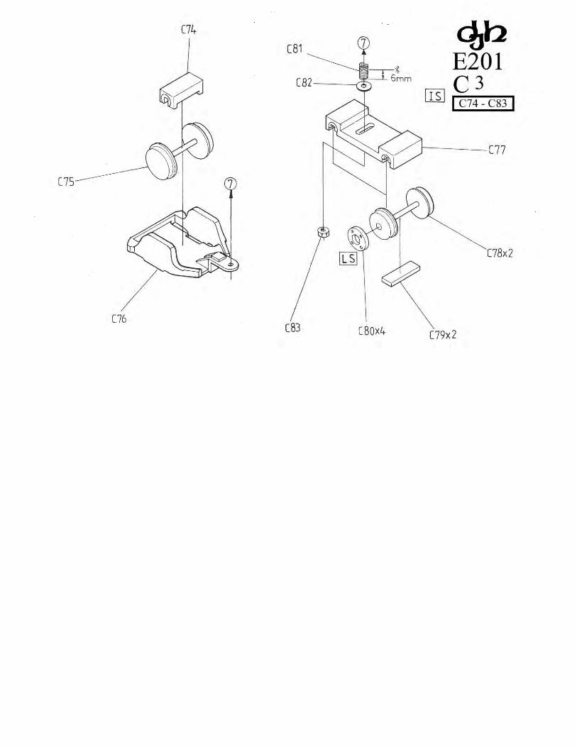
Locomotive Drawing C3 (C74 - C83)
Assemble the rear bogie (C76) using 12mm bogie wheel (C75) and mounting block (C74). Attach the bogie assembly to the chassis using the
spacer screw (C24x2) - this is the rear screw securing the keeper plate.
Assemble the front bogie (C77) using 10.5mm wheels (C78x2) fitted with wheel inserts (C80x4), and keeper plates (C79x2). Attach the front
bogie assembly to the chassis using spring (C81) -cut to 6.Omm, bearing washer (C82) and M2 nut (C83). The front bogie mounts on the M2
screw (C33) previously attached to the cylinder mounting plate (C4) - and should be fitted after the body has been fitted to the chassis.
Fit the locomotive body to the chassis using spacer screws (49x2) at the rear - see Drawing 5, and M2 screw (C73) at the front - see Drawing
C2.
Lightly oil the mechanism and test run, checking for electrical "shorts" on sharp curves etc. Also check that the motor does not overheat due
to chassis binding or stiffness.
Page 5