Embed Size (px)
Citation preview

Corresponding author: Carlo Menon E-mail: [email protected]
Journal of Bionic Engineering 11 (2014) 1–17
Abigaille-III: A Versatile, Bioinspired Hexapod for Scaling Smooth Vertical Surfaces
Michael Henrey1, Ausama Ahmed1, Paolo Boscariol1, Lesley Shannon2, Carlo Menon1
1. MENRVA Laboratory, School of Engineering Science, Simon Fraser University, Burnaby, BC, V5A 1S6 Canada 2. Reconfigurable Computing Lab, School of Engineering Science, Simon Fraser University, Burnaby, BC, V5A 1S6, Canada
Abstract This paper presents a novel, legged robot, Abigaille-III, which is a hexapod actuated by 24 miniature gear motors. This
robot uses dual-layer dry adhesives to climb smooth, vertical surfaces. Because dry adhesives are passive and stick to various surfaces, they have advantages over mechanisms such as suction, claws and magnets. The mechanical design and posture of Abigaille-III were optimized to reduce pitchback forces during vertical climbing. The robot’s electronics were designed around a Field Programmable Gate Array, producing a versatile computing architecture. The robot was reconfigured for vertical climbing with both 5 and 6 legs, and with 3 or 4 motors per leg, without changes to the electronic hardware. Abigaille-III demonstrated dexterity through vertical climbing on uneven surfaces, and by transferring between horizontal and vertical sur-faces. In endurance tests, Abigaille-III completed nearly 4 hours of continuous climbing and over 7 hours of loitering, showing that dry adhesive climbing systems can be used for extended missions.
Keywords: biologically-inspired robots, climbing robots, dry adhesive, legged robots Copyright © 2014, Jilin University. Published by Elsevier Limited and Science Press. All rights reserved. doi: 10.1016/S1672-6529(14)60015-9
1 Introduction
The ability for geckos and jumping spiders to climb vertical surfaces is aided by dry adhesion, a form of adhesion relying primarily on van der Waals forces[1–4]. This ability is of interest to scientists and engineers, and over the last two decades many successful attempts have been made to fabricate synthetic dry adhesives[5–8].
One application of dry adhesives is for climbing robots (see Fig. 1). Using dry adhesives for climbing[9–23] has potential advantages over other mechanisms in-cluding suction[24–28], magnets[29,30], and spines or claws[31,32]. Power consumption is low because dry ad-hesives are passive devices: no additional pumps or heavy systems are required for attachment. In addition, geckos have self-cleaning feet[33]; the potential exists for self-cleaning adhesives[34] and the ability to adhere to any surface like the gecko and spider.
Systems using dry adhesives may also have ad-vantages over other types of climbers when operating in specific environments. In space applications, for exam-
ple, where there are few ferromagnetic surfaces for magnets to adhere to, and there is insufficient ambient
Fig. 1 Abigaille-III, a hexapod robot, using gecko-inspired dry adhesives to climb a smooth vertical whiteboard.

Journal of Bionic Engineering (2014) Vol.11 No.1 2
pressure to allow a vacuum or suction based robot to function, a legged robot with dry adhesives could feasi-bly traverse the outside of a spacecraft for inspection or repair.
Recently prototyped climbing robots that use dry adhesion employ one of three major methods of loco-motion: tank-tracks[9–11,21], wheel-leg hybrids[12–15,22] or legs[16–20]. Besides climbing vertical surfaces, some ro-bots are also capable of transitioning between surfaces. This means that the robot can start on a horizontal sur-face and move to a vertical surface or vice-versa. Robots may also be capable of turning while travelling. While some robots can overcome small obstacles while climbing[9], climbing robots using dry adhesives that are designed to traverse uneven terrain have not yet been developed.
Successful examples of tank-tracked robots were Tankbot[9], MaTBot[21] and TBCP[10,11]. Tankbot was a tank-tracked robot that used flat or patterned elastomers to adhere to a surface[9]. In addition, it was reported to transition between surfaces, and loiter on a wall or be inverted on the ceiling. MaTBot was capable of climbing 60 degree slopes with dry adhesives, or vertical slopes with magnets[21]. TBCP-I and TBCP-II were examples of tank-tracked robots, which used Polydimethylsilox-ane (PDMS) as the substrate for their dry-adhesives[10,11]. TBCP-II was capable of climbing smooth, flat surfaces, and transferring between horizontal and vertical surfaces. Instead of using a tail to preload the adhesives, it was designed with two stages connected with a center joint.
Examples of wheel-leg hybrid robots include Waalbot[12,13] and Mini-Whegs robots[14,15] and the work by Peyvandi et al.[22]. Waalbot was capable of climbing walls and transitioning between surfaces. The second generation, Waalbot II, had strategies for detecting when its adhesion was getting close to a critical point, and recovering adhesion by rocking side to side. Waalbot-II also had an improved foot design for creating consistent preloading pressures[13]. The Mini-Whegs robots used a foot design that rotated, and held flaps of either Pressure Sensitive Adhesives (PSAs), or dry adhesives in contact with the wall[14]. This style of robot was capable of in-side transitions, and with the addition of a body joint[15], outside corner transitions. The work by Peyvandi et al. demonstrated wheel-legs that rotated out of phase with each other to self-preload[22].
Legged robots have the potential to be more dex-
terous than other styles of robot. Legged robots have an inherent safety factor during climbing[32], because if one leg loses adhesion, the other legs may still be able to hold the robot on a surface. Preliminary prototypes of legged climbing robots relying on adhesion were the Rigid Gecko Robot (RGR) and Compliant Gecko Robot (CGR) prototypes, which mimicked the gait of a climbing gecko[16]. The next example of a legged robotic platform using dry adhesion was Geckobot[17], which was also designed in the shape of a gecko. Innovations included a method of peeling its adhesives from the surface, and a method of distributing the total load through the use of an active tail. A more recent example of a legged robot using dry adhesion was Stickybot[18], a legged platform designed to mimic the gait, form, and posture of a vertically climbing gecko. Stickybot could climb a variety of surfaces with smooth to moderate roughness, including wooden doors and painted metals. Stickybot was able to climb rapidly (4 cm·s 1), however it was not reported to transfer between horizontal and vertical surfaces. Abigaille-I[19] and Abigaille-II[20] were two other preliminary prototypes which proved the fea-sibility of operating hexapod climbing robots relying on adhesion.
While Abigaille-II[20], and Abigaille-III (the present work), share a name, they are completely different ro-bots. Abigaille-II employed passive, trajectory-based methods for attaching and detaching its adhesives. In contrast, Abigaille-III has one dedicated motor per leg for active detachment, enabling a strongly preloaded foot to be detached. No data was taken on Abigaille-II’s failure rate, and observed climbing speeds underper-formed predicted speeds by four times. To reliably keep Abigaille-III on the wall, its mechanical design was optimized to reduce detaching forces on its adhesives during vertical climbing. Larger motors, bulkier struc-tural elements, and stronger preload forces allowed Abigaille-III to reliably scale vertical walls without slipping.
Following lessons learned from previous Abigaille robots, the control system of Abigaille-III was designed from scratch to maximize flexibility. Abigaille-III has a parallel control architecture implemented on a FPGA, with a separate processor and custom software for each leg. The ability to use custom software allowed the de-velopment of an open-loop torque controller used during preloads. The parallel control architecture allowed fast

Henrey et al.: Abigaille-III: A Versatile, Bioinspired Hexapod for Scaling Smooth Vertical Surfaces 3
response times and simplified the addition or removal of legs from the robot. Changing the number of motors per leg was also tested in this project. Abigaille-III replicated the climbing and transferring abilities of Abigaille-II. With superior reliability and flexibility, Abigaille-III also demonstrated climbing on uneven surfaces, and with various numbers of legs, feats that have not been reported by previous dry adhesive, climbing robots.
Section 2 introduces the configuration of the robot, including its adhesives and control system. Section 3 presents the mechanical design and analysis of the ro-bot’s posture. Section 4 presents a methodology for climbing a vertical surface, and section 5 presents a methodology for the robot to transfer between horizontal and vertical surfaces. The paper concludes with a dis-cussion of the results obtained in various climbing tests in section 6, as well as an overview of Abigaille-III’s capabilities in section 7.
2 Body, foot and control system
The implemented prototype of Abigaille-III (see Fig. 1) had six legs and 24 active Degrees of Freedom (DOF). A Computer Aided Design (CAD) model of its hexapod configuration is shown in Fig. 2a. Each leg, shown in Fig. 2b, had three active joints (2 DOF for the hip and 1 DOF for the knee), while the ankle had a 1 DOF passive revolute joint. All of the legs contained an additional motor on the foot for the purpose of detaching the adhesive from the wall during climbing (see Fig. 2c). Because the ankle joint was passive, an elastic band (see Fig. 3) was used to bring the foot parallel to the surface before attachment. The body of the robot was made from a (Poly)methyl methacrylate (PMMA) frame cut on a laser cutter (VersaLASER VLS 3.60). The holes on the frame allowed the leg positions to be changed. A Printed Circuit Board (PCB) is mounted to this frame. In pre-vious work, optimizing the static posture of a climbing hexapod to minimize its adhesive requirements (in a least-squares sense) was studied[20]. The optimal posture was found to be four legs forward, contacting the ground at an equal height on the wall, and two legs rearward (the position assumed in Fig. 1 and Fig. 2a). Using a rec-tangular body shape allowed Abigaille’s legs to be mounted close to the optimal configuration, while cre-ating a compact frame around the rectangular PCB. The robot’s leg structures were comprised of three-dimen-
sional (3D) printer plastic (InVision HR). The joint ranges selected for the leg structures of this robot are given in Table 1. The active joints were actuated by 150:1 gear motors (Pololu, Micro Metal Gearmotor HP), chosen for their small size and preferable torque-to-mass ratio. Joint positions for each leg seg-ment were measured using linear taper rotary potenti-ometers. Physical parameters of the robot are summa-rized in Table 2.
1
(a)
2 34
56
(b) (c)
5 cm
3 cm
B
A
C
D
Fig. 2 (a) CAD schematic of Abigaille-III on a wall; (b) details of a single leg; and (c) foot pad. Numbers beside legs on the CAD model indicate leg assignments used throughout this paper. In (b), joints A and B are the hip joints, C is the knee joint and D is the ankle.
Fig. 3 Detailed view of Abigaille-III’s foot showing the adhesive micro-posts (SEM micrograph) mounted on macro-posts (sche-matic) and the rigid plastic foot (photo). The detaching mecha-nism is also shown, and consists of a cam, IR sensor and detaching motor. An elastic band brings the foot parallel to the surface dur-ing attachment.
Table 1 Range of motion for Abigaille-III
Joint Range ( )
Hip, front legs 135
Hip, middle and rear legs 110
Knee 110
Ankle (passive) 105

Journal of Bionic Engineering (2014) Vol.11 No.1 4
Table 2 Physical parameters of Abigaille III
Parameter Value
Robot’s total mass 634.6 g
FPGA and PCB 105.0 g
24 motors and sensors 249.6 g
Leg structure and frame 117.4 g
Cables, fasteners and glue 162.6 g
Body envelope 0.20 m 0.21 m 0.09 m
First leg segment length 0.03 m Second leg segment length
(front and middle legs) 0.03 m
Second leg segment length (rear legs) 0.05 m
PC
5 V power supply
Coordinatingprocessor
FPGA
Leg
1Pr
oces
sor
Leg
2Pr
oces
sor
Leg
6Pr
oces
sor
PCB
Comparators and motor drivers
Leg
1
Leg
2
Leg
6
Fig. 4 Block diagram showing connections between the system components required to operate the robot. 2.1 Adhesive system
Dry adhesive foot pads held Abigaille-III to the wall during climbing. The holding strength of a synthetic dry adhesive is proportional to the preload force[35]. While a strong preload improves safety and reliability of the robot, and is thus desirable for a platform that is expected to encounter varied terrain, a method of de-taching the adhesives was needed. For this reason, the foot structure of Abigaille-III consisted of two main subsystems: the hierarchical dry adhesive, and a de-taching mechanism. A hierarchical design was used for the dry adhesive because it supports more force than a single layer design[36].
The hierarchical dry adhesive had three compo-nents: an array of PDMS micro-posts, an array of PDMS macro-posts[36] and a rigid substrate. The micro-posts were 10 m in diameter and 20 m tall, with 16 m diameter mushroom caps, which served to maximize the
contact surface area. To manufacture the micro-posts, Sylgard 184 (PDMS) was mixed by 10:1, degassed and poured onto a mould. The moulds were manufactured according to the method described in Ref. [37]. The dry adhesive was kept at 80 C for three hours before de-molding to ensure it was fully cured. This process cre-ated a 100 mm sheet of dry adhesive micro-posts.
The macro-posts were manufactured according to Ref. [36] and had a diameter of 0.8 mm, height of 1.5 mm and inter-post spacing of 1.0 mm. Once demolded, the array was a 50 mm by 100 mm continuous sheet.
The rigid substrate was a plastic foot made on a 3D printer. To assemble the hierarchical dry adhesive, the three layers (plastic foot, PDMS macro-posts, and PDMS micro-posts) were bonded together using silicone (Dow Corning 732 Multi Purpose Sealant). After curing for 24 hours, the micro and macro-post layers were trimmed to be the same size as the rigid plastic foot, creating the hierarchical design shown in Fig. 3.
The detaching mechanism consisted of a motor (Pololu, Micro Metal Gearmotor HP), an IR sensor and a cam (see Fig. 3). The motor rotated the cam into and out of contact with the wall, in order to detach the adhesive. The IR sensor on the foot detected when the cam was out of contact with the wall; this solution ensured that the cam did not interfere with the preloading process. The elastic band returned the ankle joint to its nominal angle after detachment. 2.2 Electronics and control system design
The complexity of Abigaille-III’s mechanical sys-tem created control architecture challenges. A comput-ing system with a high pin count and the ability to si-multaneously operate 24 sensor-actuator pairs was re-quired. The objective of changing the number of legs on the robot and the number of motors per leg required a flexible and versatile control architecture.
A FPGA (Xilinx Spartan 3A, Humandata devel-opment board) was selected to host the control system because it is reconfigurable and therefore a natural choice when versatility is desired. A parallel and multi-processor architecture (see Fig. 4) was imple-mented. The FPGA contained seven processors, one for each of the six robot legs and one to coordinate move-ments. The multi-processor architecture reduced the computing demand on each processor. One feature of this architecture was scalability: to use more or fewer

Henrey et al.: Abigaille-III: A Versatile, Bioinspired Hexapod for Scaling Smooth Vertical Surfaces 5
than six legs, the corresponding number of leg proces-sors were instantiated on the FPGA. A second feature of this architecture was that control loop speeds were not affected by adding or removing a leg from the robot, because the processing for each leg’s control system was independent and parallel. User Input/Ouput (IO) pins on the FPGA were configured to act as Pulse Width Modulation (PWM) outputs and Analog to Digital Converter (ADC) inputs to communicate to the sensors and actuators.
A Personal Computer (PC), shown in Fig. 4 com-municated with the FPGA in order to download a bit-stream, software and trajectory tables to Abigaille-III. This connection was only needed for configuration, and was removed during climbing.
A custom PCB (see Fig. 4) interfaced between the FPGA and the sensors and actuators on each robot leg. Motor drivers provided power to the motors according to PWM signals from the FPGA. Comparators were used by the ADCs to convert potentiometer and IR output signals to digital values. The PCB also distributed power to the FPGA, sensors and actuators.
The software on each leg processor (see Fig. 4) was responsible for the PID control loop on each joint. The coordinating processor software was responsible for managing communication and ensuring se-quence-dependent actions occurred in the proper manner. For example, it checked that a leg had detached from the wall before attempting to swing it through the air to a new position, otherwise the motor torque on the still-attached limb would cause neighbouring legs to also detach. The software and sensors are not presently ca-pable of detecting falls or the strength of each adhesive footpad.
3 Mechanical design and posture 3.1 Pitch-back failure
A climbing gecko pulls its head towards the wall to counteract the tendency to pitch-back[38]. In a similar fashion, we define a pitch-back failure as a fall caused by the front or middle feet of the robot detaching during vertical climbing.
To minimize the risk of a pitch-back failure when Abigaille-III climbed vertically, a kinematic analysis was performed to identify the climbing configuration that minimized the tension forces at the front and middle feet. This goal differs from previous force distribution
problems studied by Vidoni and Gasparetto[39], who investigated the minimization of joint torques for an eight-legged spider robot, and Mahfoudi et al.[40] who investigated a hexapod relying on friction (instead of adhesion) for locomotion. The kinematic analysis is performed assuming all of Abigaille’s legs are contact-ing the ground. Because risk of detachment increases when one leg is lifted, a safety factor is applied when adhesive preloads are designed (section 4.1).
The equation of static equilibrium is
,Gf w (1)
where f is the set of forces at the robots feet, G is the grasp matrix, and w is the wrench:
T[1 3] [1 3][ ] ,B Bw f M (2)
where fB and MB are, respectively, the external forces and moments acting on the robot’s body.
The vector f has eighteen elements, consisting of the forces at the robot’s feet, which can be separated into components along each of coordinate axis (see reference frame in Fig. 5a):
T[1 6] [1 6] [1 6][ ] .x y zf f f f (3)
where each of fx, fy and fz are vectors containing one element for each foot on the robot, (eg. fx1, fx2, …, fx6), as
fx5
fz5
dx5
dx4
dx3fz4
fz3
fx3
fx4
H
fB
COM
dx4
fx3
fz3
fy3
dy4
dz4
xy
z xz
(a) (b)
Fig. 5 Diagram of the robot on the wall, in 3D (a) and 2D (b). For clarity, in the 3D schematic, only forces for leg 3 and distances from the COM for leg 4 are shown. Distances towards the rear of the robot (i.e. dx5) are considered to be negative in this notation.

Journal of Bionic Engineering (2014) Vol.11 No.1 6
shown in Fig. 5a. Referencing this figure, which shows the displacements for a single leg, the grasp matrix for the entire robot is given by
[1 6] [1 6] [1 6]
[1 6] [1 6] [1 6]
[1 6] [1 6] [1 6][6 18]
[1 6] [1 6] [1 6]
[1 6] [1 6] [1 6]
[1 6] [1 6] [1 6]
1 0 0
0 1 00 0 1
,0
00
z y
z x
y x
Gd d
d dd d
(4)
where dx is the vector of all six displacements from the Centre of Mass (COM) of the robot to the feet in the x direction (dx1, dx2,…, dx6), and dy and dz are the vectors of six displacements in the y and z directions respectively.
When investigating the pitch-back forces, analysis was done in 2D due to Abigaille-III’s symmetry. In this case, the forces in the y axis and moments around the x and z axes are neglected, and the displacements and forces at legs 3, 4 and 5 are equal to those at legs 2, 1 and 6 respectively (see Fig. 5b). In this simplification, f is reduced to a six by one vector:
T
[1 3] [1 3] ,x zf f f (5)
where fx and fz consist of the forces only on three legs (e.g. fx3, fx4 and fx5). G simplifies to a three row by six column matrix:
[1 3] [1 3]
[1 3] [1 3]
[1 3] [1 3]
1 00 1 ,
x z
Gd d
(6)
and w simplifies to a one by three matrix:
T
[1 3] .B Bw f M (7)
The external force, fB, on the robot body (see Fig. 5b) is separated into two components: fBN, which is normal to the wall and fBF, which is parallel to the wall. Assuming that the robot is climbing vertically, the ex-ternal force due to gravity is in the direction of fBF, yielding
,BFf mg (8)
0,BNf (9)
where m is the robot’s mass and g is the acceleration due to gravity. There is assumed to be no net torque on the
body, giving the external wrench vector, w, in 2D:
T0 0 .mgw (10)
The robot’s body was assumed to be parallel to the wall, so that the distance from each leg to the wall is constant. The variables dz3, dz4 and dz5 are therefore equal, and for the rest of this section they are referred to as the height H. Eq. (1) has infinite solutions, as the rank of G is less than the number of columns in G[41]. One method of solving Eq. (1) involves minimizing the maximum detaching foot force, however we choose to compute an analytical solution, which instead provides general insights into legged robot design. The Moore-Penrose Pseudoinverse is used to compute an analytical solution:
† ,f G w (11)
which yields
T
1 2 3 ,3 3 3
mg mg mg Hmga Hmga Hmgaf (12)
3 4 51
0.5( 2 ),x x xd d d
aD
(13)
3 4 52
0.5( 2 ),x x xd d d
aD
(14)
3 4 53
0.5( 2 ),x x xd d d
aD
(15)
2 2 23 4 3 5 4 5 3 4 5.x x x x x x x x xD d d d d d d d d d (16)
Eqs. (12)–(16) represent the shear, fx, and normal, fz, forces at each foot of the climbing robot in Fig. 5b. The forces at each foot in the normal direction (fz3, fz4, and fz5) are functions of the values dx3, dx4, dx5, and H.
It can be shown that the denominator, D, of Eqs. (13)–(15) is always less than or equal to zero. Without loss of generality, the relationship Eq. (17) was assumed:
3 4 5.x x xd d d (17)
The following re-parameterizations were made using two new dummy variables A and B:
4 3 ,x xd d A (18)
5 3 .x xd d B (19)
Substituting Eq. (18) and Eq. (19) into Eq. (16) and simplifying, Eq. (20) was obtained as

Henrey et al.: Abigaille-III: A Versatile, Bioinspired Hexapod for Scaling Smooth Vertical Surfaces 7
2( ) .D A B AB (20)
From Eq. (17), both A and B are greater than zero, so the denominator, D, is less than or equal to zero. D equal to zero corresponds to all the feet placed at the same position, which is not feasible on this robot. Since dx5 is of the opposite sign to dx3 and dx4 (the rear foot is placed on the opposite side of the COM to the front and middle feet), and the denominator is less than zero, a3 is always negative. The consequence is that the rear foot is always in compression during vertical climbing.
To reduce the tension forces in the normal direction for the middle feet, which are the forces that can cause the foot to detach from the wall, a1 and a2 can be reduced, H can be reduced or a combination of the two can be performed. These observations guided the selection of gait and mechanical design of the robot. Specifically, to reduce H, Abigaille-III’s gait was designed to keep the COM close to the surface while climbing. The elec-tronics, which constitute a significant fraction of the robot’s mass, were mounted below the body, further reducing the distance of the COM to the surface. In addition, to reduce a1 and a2, the placement of the ro-bot’s feet while climbing was considered. From Eq. (13) and Eq. (14), moving the rear feet further rearward (de-creasing dx5) decreases a1 and a2 (and correspondingly the magnitude of tension force that each foot experi-ences). This is a similar principle to the function of the tail of a climbing gecko, which stretches behind the gecko to prevent it from falling[38]. With the rear feet stretched rearward, the position of the front feet and middle feet was compared to the maximum tension force at the front and middle feet. As seen in Fig. 6, the tension force is minimized when the feet are at the same distance from the COM, and when they are stretched forwards. The position used for Abigaille-III is marked on the plot (see point marked 1), and corresponded to a maximum tension force of 0.29 N. This specific position was se-lected as increasing the foot placement distances from the COM, which would have decreased the tension forces, would have required a larger body frame size or longer leg segment. Increasing the body frame size was undesirable because it would have increased the mass and size of the entire robot. A detailed discussion on the design of the leg segments is presented in the next sub-section.
Front foot distance to COM (m)0.05 0.06 0.07 0.08 0.09 0.10 0.11 0.12 0.13
0.33 N0.05
0.06
0.07
0.08
0.09
0.10
0.11
0.12
0.130.23 N
Mid
dle
foot
dis
tanc
e to
CO
M (m
)
1
Fig. 6 Contour lines showing the maximum tension forces ap-plied to the feet of a robot on the wall as a function of the front and middle foot placements (relative to the COM). The point marked 1 is the design point chosen for this robot (0.29 N). 3.2 Leg segment lengths
Both the length of a robot’s step and the mass that its motors can support while climbing or walking depend on the robot’s leg segment length. To determine appro-priate segment lengths for this robot, a kinematic analysis was performed in 2D. It was assumed the robot had its optimal configuration, namely four legs forward and two legs rearward, as previously discussed.
For a single serial manipulator[42], the Jacobian, J, relates the force, f, and torque, , according to:
T 1( ) ,f J (21)
where f is comprised of fx and fz as in Eq. (5). To obtain the Jacobian for each leg of this robot, first the forward position kinematics for a single leg are written as
1 1 2 1 2
1 1 2 1 2
cos( ) cos( ).
sin( ) sin( )l lx
z l l (22)
Taking the partial derivatives of these equations gives the Jacobian of a single leg:
1 1 2 1 2 2 1 2
1 1 2 1 2 2 1 2
sin( ) sin( ) sin( ).
cos( ) cos( ) cos( )l l l
l l lJ (23)
In a 2D case, as in the previous subsection, f is a vector comprised of fx, the shear direction force, and fz, the normal direction force. To simplify the analysis, it

Journal of Bionic Engineering (2014) Vol.11 No.1 8
was assumed that the weight of the robot was equally distributed over each foot. This means each leg must support:
,x zmgf fn
(24)
where n is the number of legs on the robot. For Abi-gaille-III, which is a hexapod, n is six. Eq. (23) and Eq. (24) were substituted into Eq. (21), and then solved for l1 and l2, which, due to the inequality in Eq. (24), were the maximum lengths of leg segments which support the robot’s mass.
The minimum values of leg segment lengths were determined by considering the robot’s typical gait. Fig. 7, which schematically represents a leg, was used to compute the minimum leg segment lengths for the robot. The leg had two segments: the first segment had length l1 and second segment had length l2. The angles 1 and 2 were the joint angles. Two constraints were imposed on the gait: the step length was d, and the joint attachment to ground distance was at least h in order to keep the robot’s body off the ground.
During a forward step, the second segment moved from position P1 to position P2, which had a separation of d (see Fig. 7). At P1, the angle of the second joint was represented as a nominal angle 2 with an offset of – (see Fig. 7). Similarly at P2, the angle was 2+ . An equation relating the height of the robot to the joint lengths and angles is written as
1 1 2 1 2sin( ) sin( ) 0.l l h (25)
The step length and second segment length are re-lated by
2 sin( ) 0.2dl (26)
In the case of 1+ 2 = 270 , which is typical for Abigaille-III’s gait, Eqs. (25) and (26) give two equa-tions with three unknowns which can be solved for l1:
1 21 2
1 ( cos(asin( ))).sin( ) 2
dl h ll
(27)
From Eq. (27) l2 must be at least d/2 due to the bounds on the arcsine function, which corresponds to the minimum segment length to produce a step of length d.
In the specific case of Abigaille-III, a 0.01 m minimum step size, d, was selected, and h had a value of
0.021 m. Typical motor torques were 18.0 g·m (found experimentally when characterizing the motors) and typical joint angles of 1 = 10 and 2 = 260 were used. These parameters were used with Eq. (21) and Eq. (27) to generate the feasible space for the leg lengths, shown as the region inside the solid line in Fig. 8. Segments A and B result from Eq. (21), while segments C and D result from Eq. (27). Once the theoretical limits were obtained, the set of feasible sizes was further reduced by fabrication constraints: a mechanical analysis showed that segments longer than 0.07 m would have exceeded the yield point of the material once loaded, and segments shorter than 0.01 m would have been of insufficient length to construct the joint. The fabrication constraints,
Fig. 7 Diagram used for computing minimum leg segment lengths.
L 2 (c
m)
Fig. 8 The feasible region of leg segment lengths is the region inside both the dotted and solid lines. Contours of equal force are labelled on the graph, and design points I (rear legs) and II (front and middle legs) are marked. Forces marked are the magnitude of the force that a leg can generate.

Henrey et al.: Abigaille-III: A Versatile, Bioinspired Hexapod for Scaling Smooth Vertical Surfaces 9
represented by the dotted line in Fig. 8, were obtained empirically. The grey lines on this plot represent con-tours of equal force that the robot can apply at its foot, and are computed using Eq. (21) with typical motor torques of 18.0 g·m and the Jacobian in Eq. (23).
The region inside both the solid and dotted lines therefore represents the feasible space. For the front and middle legs, 0.03 m segments were used (design point II in Fig. 8), and for the rear legs, a 0.03 m first segment and a 0.05 m second segment (design point I in Fig. 8) were used. Because lines A and B are sensitive to the assumption in Eq. (24), points far from these boundaries were selected. The longer second segment of the rear leg allowed this leg to extend further and better counteract the tendency to pitch-back, as analyzed in section 3.1. This analysis also justifies the tailless design: the rear legs replace the functionality of the tail, and as shown in Fig. 6, proper positioning of the legs keeps pitch-back forces low. While this optimization considers climbing on a smooth surface, this robot will also be tested while climbing on uneven surfaces, transferring and turning. Maximum step length is slightly reduced when travers-ing uneven surfaces because the leg workspace is limited. Empirically, joint range of motion was found to be most important for turning and transitioning capabilities.
4 Methodology of climbing
To climb a wall, Abigaille-III moved each foot in succession, preloading it once in place. Keeping at least five feet on the ground at a time (pentapedal gait) maximized the adhesive area in contact with the ground. Following the movement of each foot, the entire body was shifted and kept parallel to the wall during climbing.
In this work, preloading a single foot of Abi-gaille-III during vertical climbing was obtained by syn-ergistically actuating the other feet. Without a preloading control strategy, the robot was empirically observed to fall before taking a full step upwards. Finding the correct pushing or pulling forces for each foot to apply was critical – an insufficient preload could cause a pitchback failure (see section 3.1), but excessive pulling forces could also cause detachment of the feet. It should also be noted that, since the rear feet are typically in compres-sion against the wall (see Eq. (20)), it was only necessary to preload the front and middle feet. From the remainder of this section, the analysis is therefore performed on the front and middle feet (feet 1–4).
The design methodology, which was used for pre-loading the feet, is presented in Fig. 9. The goal of this method was to simplify the preloading process by con-structing an open loop torque controller which could preload each foot to a desired adhesion. Each of the steps presented in Fig. 9 is discussed in the following subsec-tions.
4.1 Step 1: Adhesion experiments
An experiment was conducted using Abigaille-III’s adhesive feet to find the relationship between preload and pull-off. A load cell was mounted on a linear stage. An adhesive foot was attached to the load cell. Using the stage, the adhesive foot was preloaded against a clean PMMA sheet. The adhesive foot remained in contact for 2 seconds and then was detached at 1 mm·s 1.
Five trials were taken at each of eight preload levels (1 N to 8 N), and four different feet were tested. Fig. 10a
Fig. 9 Methodology of determining an open loop preloading strategy.
Time (s)0 2 4 6
Forc
e (N
)
–4–3–2–1
01
345
A
D
E
CB
Nominal preload (N)0 1 2 3 4 5 6 7 8
0.0
0.5
1.0
1.5
2.0
2.5
Pull-
off t
o pr
eloa
d ra
tio
Sample 1Sample 2Sample 3Sample 4Average fit
(a) (b)
2
Fig. 10 Results from preload-pull-off tests. (a) shows a single representative trial on sample 1. Point A is where the sample comes into contact with the substrate, B is the maximum preload of 4 N, C is start of detachment 2 s later, D is the maximum pull-off force and E is when the sample is fully pulled off the substrate. Positive forces are tension, while negative forces rep-resent compressions. The combined results of trials on 4 samples are given in (b).

Journal of Bionic Engineering (2014) Vol.11 No.1 10
shows a representative preload-pull-off cycle. Fig. 10b gives a summary of the results for each sample, showing how the ratio of pull-off to preload decreased with higher preloads. Higher variance was seen at low pre-loads than higher preloads. The variance between sam-ples was likely due to minor manufacturing differences.
From Fig. 6, the theoretical static tension force on Abigaille-III’s feet was 0.29 N. However it was expected that during dynamic motions and when not all the feet were in contact with the surface, the forces at the feet would be larger. To ensure a safety factor, 4 N was se-lected as a target preload for Abigaille-III’s feet. 4.2 Step 2: Optimization of foot forces
An optimization was conducted to find the set of static forces at the robot’s feet that preloaded one adhe-sive and minimized the maximum tension force on any adhesive (see Fig. 9). The robot’s COM was assumed to be at the geometric centre of the body because a sig-nificant portion of the mass was due to the electronics, which were located near the geometric centre.
To find this optimum, the static equilibrium of forces for a robot climbing a vertical wall (see Eq. (1)) was used as an equality constraint. The notation in this section follows the 3D schematic presented in Fig. 5a.
To preload foot j, where j is one of the front or middle feet (j 1, 2, …, 4) the optimization problem was formulated as follows:
min(max( )), [1,6],zif i i j (28)
such that Eq. (1) is satisfied.
Inequality constraints were applied to limit the frictional and shear forces that a single foot could ex-perience to ±5 N:
5 5, [1,6],xif i (29)
5 5, [1,6],yif i (30)
and an equality constraint was applied to the leg to be preloaded, requiring it to have 4 N of preloading force (the target preload from section 4.1):
4.zjf (31)
A pattern search algorithm[43] was used to solve this problem, and a genetic algorithm[44] was used to verify the results. The output of this optimization is a set of optimal foot forces, f, which has the components defined
in Eq. (3). 4.3 Steps 3 and 4: Jacobian and motor experiments
By using the Jacobian, Eq. (23), and inverting Eq. (21), the joint torques, , that could apply the optimal foot forces, f, were found (as shown in Fig. 9).
.Jf (32)
Because the goal was to implement a torque con-troller, and the robot’s motors were controlled with PWM, it was necessary to find a mapping between joint torques and PWM duty cycles. The gear motors on Abigaille-III were characterized experimentally to find this relationship through the use of a torque sensor. Fig. 11 is a summary of the results. A linear mapping was used to relate motor torques to duty cycles. To find the desired PWM duty cycles, , to preload the feet, the following relationship was used:
,k c (33)
where k is the slope of the line in Fig. 11 (19.8 g·cm·% 1), is the torque found from applying the Jacobian to the
result of the foot force optimization, and c is an offset (116.4 g·cm). The computed duty cycles that map to the optimal torques obtained from Eq. (32) are tabulated in the “Theoretical duty cycles” section (top half) of Table 3. As previously mentioned, only legs 1 to 4 are con-sidered because the rear legs are assumed to be in com-pression during climbing. 4.4 Implementation
Obtaining the duty cycles to preload the robot was the final step in the methodology shown in Fig. 9. To preload the robot, the duty cycles listed in Table 3 were applied to the motors. Because the motor only behaved linearly between 20% and 80% duty cycles, duty cycles below 20% were rounded down to 0% (off) or up to 20%. The duty cycles were then tuned, and the tuned results
Duty cycle (%)0 20 40 60 80 100
500
0
1000
1500
2000
Torq
ue (g
·cm
)
150:1 Gear motorLinear fit
Fig. 11 Duty cycle and torque relationship in a 150:1 gear motor.

Henrey et al.: Abigaille-III: A Versatile, Bioinspired Hexapod for Scaling Smooth Vertical Surfaces 11
Table 3 Theoretical and tuned duty cycles for preloading
Theoretical duty cycles (%) Leg 1 Leg 2 Leg 3 Leg 4 MH MK MH MK MH MK MH MK
Leg 1 50 4 38 11 32 5 22 31Leg 2 41 40 47 25 25 38 36 25Leg 3 36 25 25 38 47 25 41 40Leg 4 22 31 32 5 38 11 50 4
Tuned duty cycles (%) Leg 1 Leg 2 Leg 3 Leg 4 MH MK MH MK MH MK MH MK
Leg 1 54 0 36 20 36 0 18 27Leg 2 36 36 54 27 27 36 36 27Leg 3 36 27 27 36 54 27 36 36
Leg
to b
e pr
eloa
ded
Leg 4 20 27 36 0 36 20 54 0
MH and MK refer to the hip and knee motors, respectively. Duty cycles are expressed as a percent, where 100 refers to a fully “on” motor.
Start Lift foot 3
Lift foot 1
Lift foot 4 Lift foot 2Place foot 4Place foot 3
Place foot 1Place foot 2 Move foot 6 Move foot 5 Final position Fig. 12 Sequence of steps Abigaille III takes to climb a wall. CAD schematics are used to highlight the motions for clarity.
Dis
tanc
e fr
om jo
int
(mm
)
Fig. 13 Workspaces for the robot’s front (a), middle (b), and rear (c) legs, generated through an iterative algorithm. are presented in the “Tuned duty cycles” section (lower half) of Table 3. Discrepancies are due to simplifications applied when modelling the system (eg. the COM loca-
tion) and manufacturing imperfections (eg. variances between adhesives and wear on the joints). The Root-Mean-Square Error (RMSE) between the theo-retical and tuned duty cycles is 6%. While the strategy was optimal for climbing, the preloading strategy also worked and was applied for transferring and other climbing motions (discussed later).
In Fig. 12, the robot is shown in its quasi-static positions during a complete walking cycle. The feet were each detached, lifted from the surface, and then replaced and preloaded 10 mm (the step size, d, used when computing the optimal leg segment lengths) for-ward of their original position to move between the start and final positions. Then the robot shifted its body to the start position, and commenced another climbing cycle. Each cycle moved the body 10 mm up the wall.
5 Methodology of transferring from hori-zontal to vertical surfaces The method used to generate the set of feasible
paths, which enabled Abigaille-III to transfer from a horizontal surface to a vertical surface, is discussed in the following three subsections. 5.1 Workspace generation
The workspace of each of Abigaille-III’s legs, which is shown in Fig. 13, was generated using the method proposed by Hansen et al.[45]. Each workspace had two limits: the inner limit was the set of positions the foot could attain that were closest to the body (dotted lines in Fig. 13), and the outer limit was the set of posi-tions the foot could attain that were furthest from the body (solid lines in Fig. 13). The hollow circles in Fig. 13 indicate where the leg was attached to the body. 5.2 Path of the COM
Abigaille-III was assumed to rotate about only one axis during a transfer, as illustrated in Fig. 14, allowing calculations to be performed in 2D. As a result, Abi-gaille-III’s body position at each point during the trans-fer (represented in Fig. 14 as a beam) has three coordi-nates: (xCM, yCM, ), where (xCM, yCM) is the location of the COM, and is the angle of the body with respect to the horizontal direction. To simulate the transfer nu-merically, was discretized into m angles:
i [0 90 ], i = 1,…, m. (34)
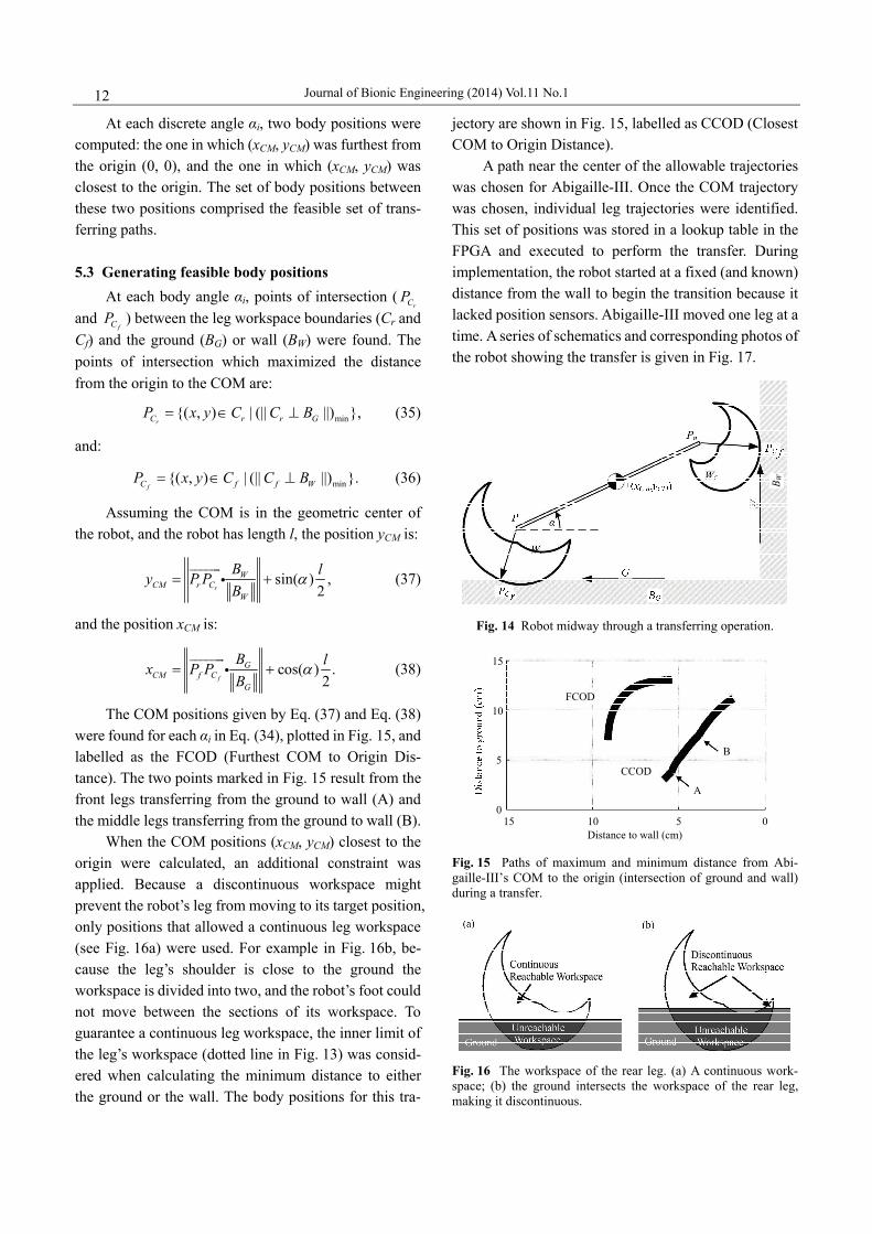
Journal of Bionic Engineering (2014) Vol.11 No.1 12
At each discrete angle i, two body positions were computed: the one in which (xCM, yCM) was furthest from the origin (0, 0), and the one in which (xCM, yCM) was closest to the origin. The set of body positions between these two positions comprised the feasible set of trans-ferring paths.
5.3 Generating feasible body positions
At each body angle i, points of intersection (rCP
and fCP ) between the leg workspace boundaries (Cr and
Cf) and the ground (BG) or wall (BW) were found. The points of intersection which maximized the distance from the origin to the COM are:
min{( , ) | (|| ||) },rC r r GP x y C C B (35)
and:
min{( , ) | (|| ||) }.fC f f WP x y C C B (36)
Assuming the COM is in the geometric center of the robot, and the robot has length l, the position yCM is:
sin( ) ,2r
WCM r C
W
B ly P PB
(37)
and the position xCM is:
cos( ) .2f
GCM f C
G
B lx P PB
(38)
The COM positions given by Eq. (37) and Eq. (38) were found for each i in Eq. (34), plotted in Fig. 15, and labelled as the FCOD (Furthest COM to Origin Dis-tance). The two points marked in Fig. 15 result from the front legs transferring from the ground to wall (A) and the middle legs transferring from the ground to wall (B).
When the COM positions (xCM, yCM) closest to the origin were calculated, an additional constraint was applied. Because a discontinuous workspace might prevent the robot’s leg from moving to its target position, only positions that allowed a continuous leg workspace (see Fig. 16a) were used. For example in Fig. 16b, be-cause the leg’s shoulder is close to the ground the workspace is divided into two, and the robot’s foot could not move between the sections of its workspace. To guarantee a continuous leg workspace, the inner limit of the leg’s workspace (dotted line in Fig. 13) was consid-ered when calculating the minimum distance to either the ground or the wall. The body positions for this tra-
jectory are shown in Fig. 15, labelled as CCOD (Closest COM to Origin Distance).
A path near the center of the allowable trajectories was chosen for Abigaille-III. Once the COM trajectory was chosen, individual leg trajectories were identified. This set of positions was stored in a lookup table in the FPGA and executed to perform the transfer. During implementation, the robot started at a fixed (and known) distance from the wall to begin the transition because it lacked position sensors. Abigaille-III moved one leg at a time. A series of schematics and corresponding photos of the robot showing the transfer is given in Fig. 17.
B W
Fig. 14 Robot midway through a transferring operation.
Distance to wall (cm)1015 5 0
0
5
10
15
FCOD
CCOD
A
B
Fig. 15 Paths of maximum and minimum distance from Abi-gaille-III’s COM to the origin (intersection of ground and wall) during a transfer.
Fig. 16 The workspace of the rear leg. (a) A continuous work-space; (b) the ground intersects the workspace of the rear leg, making it discontinuous.

Henrey et al.: Abigaille-III: A Versatile, Bioinspired Hexapod for Scaling Smooth Vertical Surfaces 13
6 Results
6.1 Climbing and loitering tests First the versatility of the control system was vali-
dated. Three configurations were tested: 18 motors (6 legs 3 motors per leg), 24 motors (6 legs 4 motors per leg, see Fig. 18a) and 20 motors (5 legs 4 motors per leg, see Fig. 18b). The ability for the robot to operate in all three configurations validated the control system versatility. The rest of the tests were conducted with 6 legs and 4 motors per leg.
Two endurance tests were conducted to test the endurance of Abigaille-III’s adhesives. In the first test, the robot was commanded to climb for approximately 0.5 m (20 minutes) up a whiteboard, and subsequently replaced at the bottom to immediately recommence climbing (without cleaning of the adhesives or white-board). Abigaille-III climbed a total of 3 hours and 55 minutes before adhesive detachment (approximately 6 m of distance travelled). This test showed that the pre-loading controller of Abigaille-III could function as the adhesion decreased, however once the adhesives had become contaminated with debris, the system failed.
A loitering endurance test was conducted by plac-ing Abigaille-III on the wall, and allowing the robot to take five steps upwards to self-preload. Then Abi-gaille-III was commanded to hold its position, which it successfully did without detachment for seven hours. After seven hours, the test was stopped with no signs of adhesive degradation or failure noted.
Tests were also conducted to show the dexterity of the robot. Abigaille-III climbed vertically along a ledge of 18 mm height in two different configurations, as shown in Fig. 19. In Fig. 20, Abigaille-III is shown climbing along a ditch and a ridge, both of 18 mm height. While ascending a vertical wall (Fig. 21), Abigaille-III
Fig. 17 Snapshots of the robot’s transferring sequence, with schematics above for clarity. In total, 31 steps are required to perform the transfer.
climbed onto a ledge protruding 5 mm from the wall. The rate of motion for some representative tests is
given in Table 4. For example, Abigaille-III was ob-served to climb 510 mm up a whiteboard in 1150 seconds, giving a rate of 0.44 mm·s 1. When climbing
Fig. 18 Abigaille-III in a 6 legged (a) and 5 legged (b) configu-ration. For the 5 legged configuration, only one rear leg is used, and it is centred.
Fig. 19 Abigaille-III climbing along a ledge with one foot (schematic (a) and photo (b)) and with two feet on the ledge (schematic (c) and photo (d)).
(b) (d)
z
y
x
y
z
Fig. 20 Abigaille-III climbing along a ditch (schematic (a) and photo (b)) and ridge (schematic (c) and photo (d)).

Journal of Bionic Engineering (2014) Vol.11 No.1 14
Fig. 21 A schematic (a) and a photo (b) of Abigaille-III climbing onto a ledge while ascending a vertical wall.
Table 4 Robot’s performance for various manoeuvres
Test Performance
Walking: tripod gait 1.08 mm·s 1
Walking: tripod gait, ledge 1.02 mm·s 1
Climbing: 6 legs 0.44 mm·s 1
Climbing: 6 legs, ledge 0.35 mm·s 1
Climbing: 5 legs 0.34 mm·s 1
Transferring from horizontal to vertical 60 s
Climbing: endurance 3 h 55 min
Loitering: endurance 7 h
Adh
esio
n fo
rce
(N)
Fig. 22 Adhesion force measured over 2000 cycles for a single foot of Abigaille-III, showing a 12% adhesive degradation over this time.
with only five legs, the climbing rate is slightly slower (0.34 mm·s 1) because a safer gait was used, with a slightly shorter step length. Abigaille-III was also capa-ble of walking on a horizontal surface with a tripod gait at 1.08 mm·s 1, along a horizontal ledge with a tripod gait at 1.02 mm·s 1 and rotating while on a vertical sur-face (up to 20 degrees from the vertical without de-tachment). Transferring from a horizontal to vertical surface took one minute. 6.2 Failure modes during climbing
Adhesive degradation were observed to occur with PDMS adhesives by other authors[46]. A controlled ex-periment was conducted on a single foot of Abigaille-III to examine adhesive degradation. The experiment setup was similar to the one described in section 4.1: using a linear stage, one foot of Abigaille-III was pressed against a glass slide 2000 times to a preload of about 2.0 N while recording the peak preload and adhesion forces with a load cell. The adhesion force was plotted against the cycle number in Fig. 22, showing only 12% degradation in strength during the test. Because during our longest endurance test (see section 6.1) the robot took an estimated 570 steps before adhesive failure, we believe that debris accumulation on the robot’s feet caused faster adhesive degradation in the endurance test than in the 2000 cycle single-foot test.
Failures while climbing were observed to fall into two broad categories: adhesive and mechanical. Adhe-sive failures generally resulted in the robot pitching back off the wall, and mechanical failures included joints or parts failing under stress. For 19 trials in which failures were observed, failures were categorized into time of occurrence and type of failure, presented in Fig. 23. Adhesive failures early into a test (0 to 2 minutes) re-sulted from poor initial climbing conditions, for example dirty adhesives or climbing surface. Mechanical failures became more common after the robot had operated for some time, and stress caused parts to fail. 6.3 Force measurements during climbing
To validate the preloading strategy, forces gener-ated at each of the front and middle feet during the climbing cycle were measured. A part of a PMMA climbing wall was cut out and replaced with a load cell (Futek LCM300) capable of measuring tensile and compressive forces up to 445 N as the robot passed over

Henrey et al.: Abigaille-III: A Versatile, Bioinspired Hexapod for Scaling Smooth Vertical Surfaces 15
Failu
res p
er m
inut
e of
ope
ratio
n
Fig. 23 Failure rates at different time periods for mechanical and adhesive failures.
Table 5 Stages of the climbing cycle
Stage Letter Stage Letter
Detach foot 3 A Preload foot 2 I Contact foot 3 with
surface B Detach foot 1 J
Preload foot 3 C Contact foot 1 with surface K
Detach foot 4 D Preload foot 1 L Contact foot 4 with
surface E Contact foot 5 M
Preload foot 4 F Contact foot 6 N
Detach foot 2 G Shift body O Contact foot 2 with
surface H
Time (s)Time (s) Time (s) Time (s)0 5 10 15 20 0 5 10 15 20 0 5 10 15 20 0 5 10 15 20
–5–4–3–2
012345 (a) Normal force on foot 1
Second cycleNormal force on foot 2Second cycle
Normal force on foot 3Second cycle
Normal force on foot 4Second cycle(b) (c) (d)
–5–4–3–2–1
012345
–5–4–3–2–1
012345
–5–4–3–2–1
012345
Forc
e (N
)
–1 Forc
e (N
)
Forc
e (N
)
Forc
e (N
)
Fig. 24 Normal forces in foot 1 (a), foot 2 (b), foot 3 (c) and foot 4 (d). The cycle in grey is a second shown to indicate the degree of repeatability of forces in each foot. Letters indicate different attaching and detaching motions as given Table 5.
it. The robot was made to climb over the load cell mul-tiple times in different positions to capture the forces at each foot.
The forces in the normal direction of the front and middle feet are shown in Fig. 24. This test showed the repeatability of the forces during a climbing step, and verified the effectiveness of the preloading strategy. Each stage of the climbing cycle and the corresponding letter are given in Table 5. The front feet (2 and 3) gen-erally supported a larger range of forces than the middle feet (1 and 4). When a foot detached, it preloaded the adjacent feet (for example A in Fig. 24a); when a foot was preloaded, it caused a detaching force at the nearby feet (for example C in Fig. 24a). Moving the feet at the rear (5 and 6) had a very minimal effect on the forces observed at the front and middle feet.
7 Conclusion
Abigaille-III is a highly versatile climbing robot. Contributions of this work include mechanical optimi-zation, a flexible FPGA based control architecture, an open loop preloading controller and a robot demon-
strating more dexterity than previous work. The robot’s leg lengths, foot placements and foot design were opti-mized for vertical climbing. These optimizations con-tributed towards nearly 4 hours of continuous climbing and 7 hours of loitering in endurance tests. Abi-gaille-III’s dexterity was demonstrated through climbing tests on uneven surfaces. With the ability to attach its feet to surfaces at different heights from the robot’s body, Abigaille-III could traverse terrain that would be diffi-cult or impossible for a tank-track or wheeled robot to traverse. The custom control system architecture al-lowed Abigaille-III to climb vertically with either 5 or 6 legs. An open-loop preloading controller was designed and its performance was validated with measurements of the normal forces at the robot’s feet while climbing. Paths for Abigaille-III to transfer from a horizontal to vertical surface were identified, and these trajectories were implemented on the robot. The use of passive ad-hesion (dry adhesives) gives Abigaille-III potential en-ergy savings over other climbing robots. By climbing with only 5 of 6 legs, Abigaille-III demonstrated a safety margin: in the future this safety margin could instead be

Journal of Bionic Engineering (2014) Vol.11 No.1 16
used to carry a battery for fully autonomous operation.
Acknowledgment
The authors thank Jeff Krahn, Yasong Li and Juan Pablo Díaz Téllez in the MENRVA Laboratory for their support in manufacturing adhesives and moulds, thoughtful discussions, and advice. This work was supported financially by NSERC, the European Space Agency (ESA), and Xilinx.
References
[1] Autumn K, Peattie A M. Mechanisms of adhesion in geckos. Integrative and Comparative Biology, 2002, 42, 1081–1090.
[2] Kesel A B, Martin A, Seidl T. Getting a grip on spider attachment: An AFM approach to microstructure adhesion in arthropods. Smart Materials and Structures, 2004, 13, 512–518.
[3] Seidl T, Vidoni R. Adhesion to flat surfaces: From spiders to stickers. Spider Ecophysiology, Springer, 2013, 463–473.
[4] Zhou M, Pesika N, Zeng H, Tian Y, Israelachvili J. Recent advances in gecko adhesion and friction mechanisms and development of gecko-inspired dry adhesive surfaces. Friction, 2011, 1, 114–129.
[5] Yu J, Chary S, Das S, Tamelier J, Pesika N S, Turner K L, Israelachvili J N. Gecko-inspired dry adhesive for robotic applications. Advanced Functional Materials, 2011, 21, 3010–3018.
[6] Murphy M P, Aksak B, Sitti M. Gecko-inspired directional and controllable adhesion. Small, 2009, 5, 170–175.
[7] Kwak M K, Jeong H E, Kim T, Yoon H, Suh K Y. Bio-inspired slanted polymer nanohairs for anisotropic wetting and directional dry adhesion. Soft Matter, 2010, 6, 1849–1857.
[8] Sameoto D, Menon C. A low-cost, high-yield fabrication method for producing optimized biomimetic dry adhesives. Journal of Micromechanics and Microengineering, 2009, 19, 115002.
[9] Unver O, Sitti M. Tankbot: A palm-size, tank-like climbing robot using soft elastomer adhesive treads. The International Journal of Robotics Research, 2010, 29, 1761–1777.
[10] Krahn J, Liu Y, Sadeghi A, Menon C. A tailless timing belt climbing platform utilizing dry adhesives with mushroom caps. Smart Materials and Structures, 2011, 20, 1–11.
[11] Gittens C, Goundar D, Law D, Minor J, Menon C. TBCP-I: towards the development of a timine belt based climbing platform. Proceedings of the IEEE/RA/EMB/IFMBE International Conference on Applied Bionics and
Biomechanics, Venice, Italy, 2010. [12] Murphy M P, Sitti M. Waalbot: An agile small-scale
wall-climbing robot utilizing dry elastomer adhesives. IEEE/ASME Transactions on Mechatronics, 2007, 12, 330–338.
[13] Murphy M P, Kute C, Menguc Y, Sitti M. Waalbot II: Adhesion recovery and improved performance of a climbing robot using fibrillar adhesives. The International Journal of Robotics Research, 2010, 30, 118.
[14] Daltorio K, Wei T E, Gorb S N, Ritzmann R E, Quinn R D. Passive foot design and contact area analysis for climbing Mini-Whegs. Proceedings of the IEEE International Conference on Robotics and Automation, Roma, Italy, 2007, 1274–1279.
[15] Daltorio K A, Witushynsky T C, Wile G D, Palmer L R, Malek A A, Ahmad M R, Southard L, Gorb S N, Ritzmann R E, Quinn R D. A body joint improves vertical to horizontal transitions of a wall-climbing robot. Proceedings of the IEEE International Conference on Robotics and Automation, Pasedena, USA, 2008, 3046–3051.
[16] Menon C, Sitti M. A biomimetic climbing robot based on the gecko. Journal of Bionic Engineering, 2006, 3, 115–125.
[17] Unver O, Uneri A, Aydemir A, Sitti M. Geckobot: A gecko inspired climbing robot using elastomer adhesives. Proceedings of the IEEE International Conference on Robotics and Automation, Orlando, Florida, 2006, 2329–2335.
[18] Kim S, Spenko M, Trujillo S, Heyneman B, Mattoli V, Cutkosky M R. Whole body adhesion: Hierarchical, directional and distributed control of adhesive forces for a climbing robot. Proceedings of the IEEE International Conference on Robotics and Automation, Roma, Italy, 2007, 1268–1273.
[19] Menon C, Li Y, Sameoto D, Martens C. Abigaille-I: Towards the development of a spider-inspired climbing robot for space use. Proceedings of the 2nd IEEE RAS & EMBS International Conference on Biomedical Robotics and Biomechatronics, Scottsdale, USA, 2008, 384–389.
[20] Li Y, Ahmed A, Sameoto D, Menon C. Abigaille II: Toward the development of a spider-inspired climbing robot. Robotica, 2012, 30, 79–89.
[21] Fremerey M, Gorb S, Heepe L, Kasper D, Witte H. MaTBot: A Magnetoadhesive track robot for the inspection of artificial smooth substrates. International Symposium on Adaptive Motion of Animals and Machines, Awaji, Japan, 2011, 19–20.
[22] Peyvandi A, Soroushian P, Lu J. A new self-loading locomotion mechanism for wall climbing robots employing

Henrey et al.: Abigaille-III: A Versatile, Bioinspired Hexapod for Scaling Smooth Vertical Surfaces 17
biomimetic adhesives. Journal of Bionic Engineering, 2013, 10, 12–18.
[23] Boscariol P, Henrey M, Li Y, Menon C. Optimal gait for bioinspired climbing robots using dry adhesives: A quasi-static investigation. Journal of Bionic Engineering, 2013, 10, 1–11.
[24] Zhang H, Zhang J, Zong G, Wang W, Liu R. Sky Cleaner 3: A real pneumatic climbing robot for glass-wall cleaning. IEEE Robotics & Automation Magazine, 2006, 13, 32–41.
[25] Qian Z Y, Zhao Y Z, Fu Z, Cao Q X. Design and realization of a non-actuated glass-curtain wall-cleaning robot prototype with dual suction cups. The International Journal of Advanced Manufacturing Technology, 2006, 30, 147–155.
[26] Shang J, Sattar T, Chen S, Bridge B. Design of a climbing robot for inspecting aircraft wings and fuselage. Industrial Robot: An International Journal, 2007, 34, 495–502.
[27] Elkmann N, Felsch T, Sack M, Böhme T, Hortig J, Saenz J. Modular climbing robot for service-sector applications. Industrial Robot: An International Journal, 1999, 26, 460–465.
[28] Luk B L, Cooke D S, Galt S, Collie A A, Chen S. Intelligent legged climbing service robot for remote maintenance applications in hazardous environments. Robotics and Autonomous Systems, 2005, 53, 142–152.
[29] Xu Z, Ma P. A wall-climbing robot for labelling scale of oil tank’s volume. Robotica, 2002, 20, 209–212.
[30] Shen W, Gu J, Shen Y. Permanent magnetic system design for the wall-climbing robot. Applied Bionics and Biomechanics, 2006, 3, 151–159.
[31] Palmer L R, Diller E D, Quinn R D. Design of a wall-climbing hexapod for advanced maneuvers. Proceedings of the IEEE/RSJ International Conference on Intelligent Robots and Systems, St. Louis, USA, 2009, 625–630.
[32] Spenko M J, Haynes G C, Saunders J A, Cutkosky M R, Rizzi A A, Full R J, Koditschek D E. Biologically inspired climbing with a hexapedal robot. Journal of Field Robotics, 2008, 25, 223–242.
[33] Hansen W R, Autumn K. Evidence for self-cleaning in gecko setae. Proceedings of the National Academy of
Sciences of the United States of America, 2005, 102, 385–389.
[34] Lee J, Fearing R S. Contact self-cleaning of synthetic gecko adhesive from polymer microfibers. Langmuir, 2008, 24, 10587–10591.
[35] Greiner C, del Campo A, Arzt E. Adhesion of bioinspired micropatterned surfaces: Effects of pillar radius, aspect ratio, and preload. Langmuir, 2007, 23, 3495–3502.
[36] Li Y, Sameoto D, Menon C. Enhanced compliant adhesive design and fabrication with dual-level hierarchical structure. Journal of Bionic Engineering, 2010, 7, 228–234.
[37] Krahn J, Sameoto D, Menon C. Controllable biomimetic adhesion using embedded phase change material. Smart Materials and Structures, 2011, 20, 015014.
[38] Jusufi A, Goldman D I, Revzen S, Full R J. Active tails enhance arboreal acrobatics in geckos. Proceedings of the National Academy of Sciences of the United States of America, 2008, 105, 4215–4219.
[39] Vidoni R, Gasparetto A. Efficient force distribution and leg posture for a bio-inspired spider robot. Robotics and Autonomous Systems, 2011, 59, 142–150.
[40] Mahfoudi C, Djouani K, Rechak S, and Bouaziz M. Optimal force distribution for the legs of a hexapod robot. Proceedings of the International Conference on Control Applications, Istanbul, Turkey, 2003, 657–663.
[41] Vujicuc M. Linear Algebra Throughly Explained, 1st ed, Springer, Berlin, 2007.
[42] Craig J J. Introduction to Robotics: Mechanics and Control, 3rd ed, Pearson Education, Upper Saddle River, 2005.
[43] Audet C, Dennis J E. Analysis of Generalized Pattern Searches. SIAM Journal of Optimization, 2003, 13, 889–903.
[44] Mitchell M. An Introduction to Genetic Algorithms, MIT Press, Cambridge, 1998.
[45] Hansen J A, Gupta K C, Kazerounian S M K. Generation and evaluation of the workspace of a manipulator. The International Journal of Robotics Research, 1983, 2, 22–31.
[46] Kroner E, Maboudian R, Arzt E. Adhesion characteristics of PDMS surfaces during repeated pull-off force measurements. Advanced Engineering Materials, 2010, 12, 398–404.

![FLUID POWER/POWER TRANSMISSION High Frequency Hexapod Testing · [] High Frequency Hexapod Testing C ontrol refinements to a six degree of freedom hydraulic hexapod used for automobile](https://img.pdfslide.us/doc/110x75/5b3facbc7f8b9a4b3f8c68da/fluid-powerpower-transmission-high-frequency-hexapod-high-frequency-hexapod.jpg)