Embed Size (px)
Citation preview
Aa
Ma
b
a
ARA
KAAAEC
C
1d
Renewable and Sustainable Energy Reviews 15 (2011) 2061–2072
Contents lists available at ScienceDirect
Renewable and Sustainable Energy Reviews
journa l homepage: www.e lsev ier .com/ locate / rser
utomobile adsorption air-conditioning system using oil palm biomass-basedctivated carbon: A review
ohammad Omar Abdullaha,∗, Ivy Ai Wei Tana, Leo Sing Limb
Department of Chemical Engineering and Energy Sustainability, Faculty of Engineering, Universiti Malaysia Sarawak, 94300 Kota Samarahan, MalaysiaEnergy Research Group Laboratory, Faculty of Engineering, Universiti Malaysia Sarawak, 94300 Kota Samarahan, Malaysia
r t i c l e i n f o
rticle history:eceived 27 October 2010ccepted 24 January 2011
eywords:dsorptionir-conditioningutomobilexhaust gas
a b s t r a c t
Refrigeration and air-conditioning technology are required to evolve in accordance to Montreal Proto-col adopted in 1987 and Kyoto Protocol in 1997. This regulation concerns about the climate change inan attempt to phase-out chlorofluorocarbons (CFCs), followed by hydro-chlorofluorocarbons (HCFCs)and then moving to 1,1,1,2-tetrafluoroethane (HFC-134a) starting 2011. This trend leads to a strongdemand of new systems for air-conditioning, especially in automobile. Adsorption cooling system, amongother proposed cooling technologies, has a very good potential for automobile applications. Hence, thereexists a need for a creative design and innovation to allow adsorption technology to be practical for air-conditioning in automobile in a near future. Oil palm shell-based activated carbon has been widely applied
oefficient of performance (COP) in various environmental pollution control technologies, mainly due to its high adsorption performanceyet low cost. However, limited studies have been carried out on the characteristics and application ofoil palm shell-based activated carbon in adsorption air-conditioning system. This paper is to present acomprehensive review on the past efforts in the field of adsorption air-conditioning systems for automo-bile. This work also aims to investigate the physicochemical properties of oil palm shell-based activatedcarbon and its feasibility for application in adsorption air-conditioning system. Some of the limitations
are outlined and suggestions for future improvements are pointed out.© 2011 Elsevier Ltd. All rights reserved.
ontents
1. Introduction . . . . . . . . . . . . . . . . . . . . . . . . . . . . . . . . . . . . . . . . . . . . . . . . . . . . . . . . . . . . . . . . . . . . . . . . . . . . . . . . . . . . . . . . . . . . . . . . . . . . . . . . . . . . . . . . . . . . . . . . . . . . . . . . . . . . . . . . . . 20622. Activated carbon . . . . . . . . . . . . . . . . . . . . . . . . . . . . . . . . . . . . . . . . . . . . . . . . . . . . . . . . . . . . . . . . . . . . . . . . . . . . . . . . . . . . . . . . . . . . . . . . . . . . . . . . . . . . . . . . . . . . . . . . . . . . . . . . . . . . . 2062
2.1. Properties and structures of activated carbon . . . . . . . . . . . . . . . . . . . . . . . . . . . . . . . . . . . . . . . . . . . . . . . . . . . . . . . . . . . . . . . . . . . . . . . . . . . . . . . . . . . . . . . . . . . . . . . 20632.2. Types of activated carbon . . . . . . . . . . . . . . . . . . . . . . . . . . . . . . . . . . . . . . . . . . . . . . . . . . . . . . . . . . . . . . . . . . . . . . . . . . . . . . . . . . . . . . . . . . . . . . . . . . . . . . . . . . . . . . . . . . . . 20632.3. Oil palm shell-derived activated carbon . . . . . . . . . . . . . . . . . . . . . . . . . . . . . . . . . . . . . . . . . . . . . . . . . . . . . . . . . . . . . . . . . . . . . . . . . . . . . . . . . . . . . . . . . . . . . . . . . . . . . 20632.4. Preparation and characterization of activated carbon . . . . . . . . . . . . . . . . . . . . . . . . . . . . . . . . . . . . . . . . . . . . . . . . . . . . . . . . . . . . . . . . . . . . . . . . . . . . . . . . . . . . . . . 2063
2.4.1. Surface area and pore characteristics . . . . . . . . . . . . . . . . . . . . . . . . . . . . . . . . . . . . . . . . . . . . . . . . . . . . . . . . . . . . . . . . . . . . . . . . . . . . . . . . . . . . . . . . . . . . . . 20642.4.2. Particle size distribution . . . . . . . . . . . . . . . . . . . . . . . . . . . . . . . . . . . . . . . . . . . . . . . . . . . . . . . . . . . . . . . . . . . . . . . . . . . . . . . . . . . . . . . . . . . . . . . . . . . . . . . . . . . . 20642.4.3. Surface morphology . . . . . . . . . . . . . . . . . . . . . . . . . . . . . . . . . . . . . . . . . . . . . . . . . . . . . . . . . . . . . . . . . . . . . . . . . . . . . . . . . . . . . . . . . . . . . . . . . . . . . . . . . . . . . . . . 20642.4.4. Proximate analysis . . . . . . . . . . . . . . . . . . . . . . . . . . . . . . . . . . . . . . . . . . . . . . . . . . . . . . . . . . . . . . . . . . . . . . . . . . . . . . . . . . . . . . . . . . . . . . . . . . . . . . . . . . . . . . . . . . 20642.4.5. Surface chemistry . . . . . . . . . . . . . . . . . . . . . . . . . . . . . . . . . . . . . . . . . . . . . . . . . . . . . . . . . . . . . . . . . . . . . . . . . . . . . . . . . . . . . . . . . . . . . . . . . . . . . . . . . . . . . . . . . . . 2064
2.5. Classification of adsorption . . . . . . . . . . . . . . . . . . . . . . . . . . . . . . . . . . . . . . . . . . . . . . . . . . . . . . . . . . . . . . . . . . . . . . . . . . . . . . . . . . . . . . . . . . . . . . . . . . . . . . . . . . . . . . . . . . 20652.6. Adsorption isotherms . . . . . . . . . . . . . . . . . . . . . . . . . . . . . . . . . . . . . . . . . . . . . . . . . . . . . . . . . . . . . . . . . . . . . . . . . . . . . . . . . . . . . . . . . . . . . . . . . . . . . . . . . . . . . . . . . . . . . . . . 20652.7. Adsorption kinetics . . . . . . . . . . . . . . . . . . . . . . . . . . . . . . . . . . . . . . . . . . . . . . . . . . . . . . . . . . . . . . . . . . . . . . . . . . . . . . . . . . . . . . . . . . . . . . . . . . . . . . . . . . . . . . . . . . . . . . . . . . . 20652.8. Adsorption thermodynamics . . . . . . . . . . . . . . . . . . . . . . . . . . . . . . . . . . . . . . . . . . . . . . . . . . . . . . . . . . . . . . . . . . . . . . . . . . . . . . . . . . . . . . . . . . . . . . . . . . . . . . . . . . . . . . . . . 2065
3. Adsorption versus vapour compression systems in automobile . . . . . . . . . .4. Theoretical consideration of adsorption air-conditioning. . . . . . . . . . . . . . . . .
4.1. Adsorption cycle . . . . . . . . . . . . . . . . . . . . . . . . . . . . . . . . . . . . . . . . . . . . . . . . . . . .4.1.1. Basic of adsorption . . . . . . . . . . . . . . . . . . . . . . . . . . . . . . . . . . . . . . . .
∗ Corresponding author. Tel.: +60 82 583280.E-mail addresses: [email protected], [email protected] (M.O. Abdullah).
364-0321/$ – see front matter © 2011 Elsevier Ltd. All rights reserved.oi:10.1016/j.rser.2011.01.012
. . . . . . . . . . . . . . . . . . . . . . . . . . . . . . . . . . . . . . . . . . . . . . . . . . . . . . . . . . . . . . . . . . . . . . . . . . 2065. . . . . . . . . . . . . . . . . . . . . . . . . . . . . . . . . . . . . . . . . . . . . . . . . . . . . . . . . . . . . . . . . . . . . . . . . . 2066. . . . . . . . . . . . . . . . . . . . . . . . . . . . . . . . . . . . . . . . . . . . . . . . . . . . . . . . . . . . . . . . . . . . . . . . . . 2066. . . . . . . . . . . . . . . . . . . . . . . . . . . . . . . . . . . . . . . . . . . . . . . . . . . . . . . . . . . . . . . . . . . . . . . . . 2066
2
1
tjaet12totnatorwdiofsmbsawhtcfp
tmaapioc[hca
osttatc
062 M.O. Abdullah et al. / Renewable and Sustainable Energy Reviews 15 (2011) 2061–2072
4.1.2. Ideal adsorption cycle . . . . . . . . . . . . . . . . . . . . . . . . . . . . . . . . . . . . . . . . . . . . . . . . . . . . . . . . . . . . . . . . . . . . . . . . . . . . . . . . . . . . . . . . . . . . . . . . . . . . . . . . . . . . . . 20664.1.3. Thermodynamic analysis of adsorption cycle . . . . . . . . . . . . . . . . . . . . . . . . . . . . . . . . . . . . . . . . . . . . . . . . . . . . . . . . . . . . . . . . . . . . . . . . . . . . . . . . . . . . . . 2067
4.2. Adsorbent–adsorbate pairs . . . . . . . . . . . . . . . . . . . . . . . . . . . . . . . . . . . . . . . . . . . . . . . . . . . . . . . . . . . . . . . . . . . . . . . . . . . . . . . . . . . . . . . . . . . . . . . . . . . . . . . . . . . . . . . . . . . 20674.3. Performance analysis . . . . . . . . . . . . . . . . . . . . . . . . . . . . . . . . . . . . . . . . . . . . . . . . . . . . . . . . . . . . . . . . . . . . . . . . . . . . . . . . . . . . . . . . . . . . . . . . . . . . . . . . . . . . . . . . . . . . . . . . . 2068
5. Application of adsorption technologies in automobile air-conditioning. . . . . . . . . . . . . . . . . . . . . . . . . . . . . . . . . . . . . . . . . . . . . . . . . . . . . . . . . . . . . . . . . . . . . . . . . . . . 20686. Outlook of automobile adsorption air-conditioning . . . . . . . . . . . . . . . . . . . . . . . . . . . . . . . . . . . . . . . . . . . . . . . . . . . . . . . . . . . . . . . . . . . . . . . . . . . . . . . . . . . . . . . . . . . . . . . . 20707. Conclusions . . . . . . . . . . . . . . . . . . . . . . . . . . . . . . . . . . . . . . . . . . . . . . . . . . . . . . . . . . . . . . . . . . . . . . . . . . . . . . . . . . . . . . . . . . . . . . . . . . . . . . . . . . . . . . . . . . . . . . . . . . . . . . . . . . . . . . . . . . 2071
Acknowledgements . . . . . . . . . . . . . . . . . . . . . . . . . . . . . . . . . . . . . . . . . . . . . . . . . . . . . . . . . . . . . . . . . . . . . . . . . . . . . . . . . . . . . . . . . . . . . . . . . . . . . . . . . . . . . . . . . . . . . . . . . . . . . . . . . . 2071References . . . . . . . . . . . . . . . . . . . . . . . . . . . . . . . . . . . . . . . . . . . . . . . . . . . . . . . . . . . . . . . . . . . . . . . . . . . . . . . . . . . . . . . . . . . . . . . . . . . . . . . . . . . . . . . . . . . . . . . . . . . . . . . . . . . . . . . . . . . 2071
. Introduction
In general, automobile air-conditioning systems are designedo provide comfort for the driver and the passengers during aourney. The conventional electrical-driven compression systemsre widely used in almost all of the automobiles today. How-ver, air-conditioning technology is required to evolve due tohe new environmental regulations, notably Montreal Protocol in987, Kyoto Protocol in 1997 and European Commission Regulation037/2000. These regulations are concerning about the depletion ofhe ozone layer and also global warming, which decided to phase-ut CFCs and followed by HCFCs and HFC-134a. As a result, thisrend has led to a strong demand for a new air-conditioning tech-ology. Among the existing air-cooling technologies, adsorptionir-cooling system has good energy-saving potential. The advan-ages of this system are: it can be powered by using waste heatr solar, long lasting, low maintenance cost, used non-pollutingefrigerants and friendly to environment [1]. Unfortunately, noorking prototype has been practically run in present automobilesue to various restrictions, due to sizing and cooling capacity lim-
tations. Adsorption refrigeration cycle powered by solar energyr waste heat exhausted from engines has been successfully usedor ice making and cold production. For example, carbon–ammoniaolar refrigerator for vaccine cooling [2], solar adsorption iceaker [3], silica gel–water adsorption refrigeration cycle driven
y waste heat of near-ambient temperature [4], zeolite–waterolar cold storage system [5] and a combined solar thermoelectric-dsorption cooling system using activated carbon–methanolorking pair [6]. Based on the cited literatures, extensive researchas been performed on adsorption refrigeration, but research onhe possibility of applying this technology for automobile air-onditioning purposes is still rare. Therefore this review paperocuses on the adsorption system for automobile air-conditioningurpose.
Activated carbons have been tested with various adsorbates ashe working pair in adsorption cooling system [7–10], however,
ost of the activated carbons studied were commercially avail-ble activated carbons which were synthesized from expensivend non-renewable materials. Activated carbon derived from oilalm shell has been widely used in various applications especially
n environmental control technologies such as for the adsorptionf methane [11], hexavalent chromium [12], copper ions [13], 4-hloroguaiacol [14], phenol [15] and treatment of landfill leachate16]. Oil palm shell-based activated carbon has been proved to giveigh adsorption performance, however limited studies have beenarried out on the application of this activated carbon in adsorptionir-conditioning systems.
Besides, not many studies have been carried out on the physic-chemical properties of activated carbon which are the mostignificant parameters affecting the adsorption performance and
adsorbent–adsorbate behaviour and on an exact understanding ofthe influence of operating conditions and the working pair char-acteristics on the performance, including the evaluation of theadsorption capacity and rate of adsorption of the activated carbonon the adsorbate [7].
2. Activated carbon
Activated carbon encompasses a broad range of amorphouscarbon-based materials having high degrees of porosity and exten-sive surface areas. The properties of each finished activated carbonare influenced by the starting materials used and by the condi-tions of activation. The result is a myriad of activated carbons,each having a specific utility. The method most frequently usedfor preparation of activated carbon involves carbonization of theprecursors at high temperature in an inert atmosphere followedby activation. There are mainly two different methods for acti-vation, namely physical and chemical. Physical activation processcomprises treatment of the char obtained from carbonization withsome oxidizing gases, generally steam or carbon dioxide at hightemperature. The porous structure is created due to the elimi-nation of volatile matter during pyrolysis and the carbon on thechar is removed during activation. The main function of gasi-fication is to widen the pores, creating large mesoporosity. Inchemical activation, a chemical agent is impregnated to the pre-cursors prior to heat treatment in an inert atmosphere. The poresare developed by dehydration and oxidation reactions of the chem-icals.
Activated carbons find wide applications as adsorbents, catalystor catalyst supports. Activated carbon is one of the most importantadsorbents from an industrial point of view. The main applica-tion of this adsorbent is for separation and purification of gaseousand liquid phase mixtures. In general, activated carbons can bedivided into gas-adsorbing and liquid-phase carbons. The maindistinction between gas-adsorbing and liquid-phase carbons liesin the pore size distribution. Basically, the structure of activatedcarbons containing pores are classified according to the Interna-tional Union of Pure and Applied Chemistry [17] classification intothree groups, micropores (pore size < 2 nm), mesopores (pore size2–50 nm) and macropores (pore size > 50 nm). Gas-adsorbing car-bons usually have the most pore volume in the micropore andmacropore ranges, whereas liquid-phase carbons have significantpore volume in the mesopore or transitional pore range, permittingready access of liquids to the micropore structure which resultsin rapid attainment of adsorption equilibrium for smaller adsor-bates.
Activated carbons concern many industries as diverse as foodprocessing, pharmaceuticals, chemical, petroleum, nuclear andautomobile, because of their adsorptive properties due to highavailable surface area which is presented in their extensive internal
he cooling efficiency of an adsorption cooling system. Adsorp-ion characteristics of activated carbon can be determined by thedsorption isotherms, kinetics and mechanism. It is of impor-ance to precisely analyze the performance of an adsorptionooling system, based on an accurate determination of the
pore structure. The high porosity of activated carbons is a function
of both the precursor as well as the scheme of activation. Activatedcarbons are now frequently used in environmental processes forremoving toxic gases and in wastewater as well as potable watertreatments.
inable
2
rcvTepia[
tTmsalob[ngista
2
saoiab
•
•
Gaet
rllpi
2
ctttcqc
M.O. Abdullah et al. / Renewable and Susta
.1. Properties and structures of activated carbon
Activated carbon has specific properties depending on the mate-ial source and the mode of activation. In both physical andhemical activation processes, knowledge of different variables isery important in developing the porosity of the activated carbon.he adsorption capacity of an activated carbon is related to its prop-rties such as surface area, pore volume, pore size distribution andore structure. The development of micropores and mesopores is
mportant as it allows the activated carbon to adsorb large amountsnd various types of adsorbates either from gas or liquid streams18].
Activated carbons are materials having complex porous struc-ures with associated energetic as well chemical inhomogeneities.heir structural heterogeneity is a result of existence of micropores,esopores and macropores of different sizes and shapes [19]. The
tructure of an activated carbon is comprised of carbon atoms thatre ordered in parallel stacks of hexagonal layers, extensively cross-inked and tetrahedrally bonded. Several heteroatoms includingxygen, hydrogen, nitrogen and others can be found in the car-on matrix in the form of single atoms and/or functional groups20]. The large surface area of an activated carbon is associated withear-molecular size pores and capillaries formed within the carbonranules by selective burning and oxidation of raw material dur-ng activation. Commercial activated carbons typically have totalurface area in the range from 450 to 1500 m2/g as measured byhe nitrogen adsorption method. The pore volumes of commercialctivated carbons normally range from 0.5 to 1.5 cm3/g [21].
.2. Types of activated carbon
A challenge in activated carbon production is to produce verypecific carbons with particular characteristics. The forms and char-cteristics of the activated carbons prepared are highly dependentn the precursors and the activation methods used. Different phys-cal forms of activated carbons are produced depending on theirpplications [22]. The most common forms by which activated car-ons can be found are:
granular activated carbon (GAC) to be used in adsorptioncolumns, andpowdered activated carbon (PAC) for use in batch adsorption fol-lowed by filtration.
GAC can be prepared from hard material such as coconut shell.AC is commonly used as column filler for gas or liquid treatmentsnd can be regenerated after use. However, one of the problemsncountered in the application of adsorption processes to waterreatment is the slow intraparticular diffusion in GAC.
In contrast, PAC is obtained when small particles compose theaw material such as wood sawdust and normally mixed with theiquid to be treated and afterwards disposed off. PAC presents aarge external surface and a small diffusion distance, therefore itrovides faster adsorption velocities and is preferred for adsorption
n liquid phase.
.3. Oil palm shell-derived activated carbon
Wood, bituminous coal, lignite, peat, petroleum residues andoconut shell are some of the conventional starting materials usedo produce activated carbons. The selection of the precursor essen-
ially determines the range of adsorptive and physical propertieshat can be attained in the activated carbon. The choice of pre-ursor is largely dependent on its availability, cost, consistency ofuality and purity [23]. In fact, any cheap material with high carbonontent and low inorganics can be used as a raw material for theEnergy Reviews 15 (2011) 2061–2072 2063
production of activated carbon. Due to the high cost of commer-cial activated carbons that limits their wide use, currently focushas been given on production of activated carbons from cheapand renewable materials such as agricultural wastes. Agriculturalby-products have been proved to be promising raw materials forthe production of activated carbons because of their availability atlow price and they can be used to produce activated carbons witha high adsorption capacity and considerable mechanical strength[24]. Agricultural biomass is considered to be very important feed-stock in virtue of especially two facts: they are renewable sourcesand low cost materials. Besides, this biomass contains high concen-tration of volatiles and low ash content which is ideal for creatinghighly porous structures within the activated carbon matrix [25]. InMalaysia, agricultural by-products are the most abundant biomassresources, exceeding 70 million tonnes annually. The high produc-tion rate of biomass throughout the year is mainly due to the highsunlight intensity/time and high rainfall. Palm oil industry is themain contributor of agricultural biomass in Malaysia, generating94% of the total agricultural biomass [26].
One significant problem faced by the agricultural industries cur-rently is the managing of the by-products and wastes produced. Thedisposal of the by-products in large quantity is difficult and expen-sive to the industries. At present, some agricultural by-products arebeing used as boiler fuel, however large portion of the wastes areeither burnt using open burning or dumped aside which will causeenvironmental pollution as well as harboring pests and diseases.This will result not only in wastage, but also severe economic setback to the industries and the country. Therefore in order to makebetter use of these abundant agricultural by-products, they needto be utilized effectively to the point that they can be consideredas valuable products that will serve as raw materials to supportanother industry. For this purpose, it is proposed to convert the neg-ative value agricultural by-products into valuable products such asactivated carbons. The use of agricultural wastes for the produc-tion of activated carbons is very attractive from the point of viewof their contribution to decrease the cost of waste disposal, hencehelping in environmental protection.
Malaysia is one of the largest palm oil producing countriesin the world. One of the significant problems in the palm fruitprocessing is managing of the wastes generated during the pro-cesses. Every year, the oil palm industry generates about 10 milliontonnes of solid wastes and this is expected to continue to increase.Palm oil mills in Malaysia produce about 4.3 million tonnes of shellannually [27]. Oil palm shell has been successfully converted intoactivated carbon and characterized by previous researchers, mainlyfor removal of gaseous pollutants [28–32]. Recently, oil palm shell-based activated carbon has been commercialized and widely used,e.g. for the adsorption of methane [11], hexavalent chromium [12],copper ions [13], 4-chloroguaiacol [14], phenol [15] and treatmentof landfill leachate [16], due to the high adsorption performance.However, the application of this activated carbon in adsorption air-conditioning systems is still limited and hence its potential to beused as the adsorbent in automobile adsorption air-conditioningsystems worth to be investigated.
2.4. Preparation and characterization of activated carbon
Basically, there are two main steps in the preparation andmanufacture of activated carbon: the carbonization of the carbona-ceous raw material in the absence of oxygen to break down thecross-linkage between carbon atoms, followed by the activation
of the carbonized product, known as char, for further pore devel-opment [24]. Carbonization is a process by which solid residueswith increasing content of the element carbon are formed fromorganic material, usually by pyrolysis in an inert atmosphere. Thepores formed during carbonization stage are normally narrowed,
2 inable
cdtmtstba
acfistbtrtocaittt
dapavsuaTiomotlaomap
2
amacr[lplit
mbp
064 M.O. Abdullah et al. / Renewable and Susta
onstricted or even blocked by deposited tarry substances. Theeposition process occurs while the volatiles are diffusing out ofhe pore structure into the gas mainstream. Some of the substances
ay collide with the pore walls, which may lead to hydrocrackinghat result in carbon deposition [33]. The study of utilizing guavaeed-based activated carbon to adsorb methylene blue revealedhat carbonization alone yielded a poor adsorbing activated car-on due to the incomplete decomposition of organic constituentss the pores were blocked by carbonization by-products [34].
Activated carbons are commonly characterized by the mode ofctivation. Knowledge of different variables during activation pro-ess is very important in developing the porosity of carbon soughtor a given application. Activation is needed to enhance the poros-ty and to clean out the pores as during carbonization, the poretructures are filled with tar products which decompose and blockhe pores [35]. Activation process can be divided into three stagesased on the variation activity of different parts of the carbon struc-ure. At the initial stage, tarry materials that cause pore clogging areemoved thus exposing the surface of the elementary carbon crys-al to the activating agent. The second stage involves the burningf elementary crystal followed with disordered and parallel grouprystals. This reaction will be terminated when the single crystalsre burnt out or when adjoining crystal of the proper orientations exhausted. The third stage involves deep oxidation which leadso a reduction in the total micropore volume due to the burning ofhe walls between the neighbouring pores. The process results inhe formation of wider pores as a consequence of collapsing walls.
The adsorption performance of an activated carbon is depen-ent on its properties and characteristics. Therefore, both physicalnd chemical characterizations need to be carried out on the pre-ared activated carbons following the standard methods in order tossure its accuracy and consistency. Physical characterization pro-ides technical aspects in terms of surface area, pore volume, poreize distribution and surface morphology. Activated carbon has anique surface property due to its non-polar or slightly polar natures a result of the surface oxide groups and inorganic impurities.his has given activated carbon several advantages, such as thatt is used to perform separation and purification processes with-ut requiring prior stringent moisture removal. Besides, it adsorbsore non-polar and weakly polar organic molecules compared to
ther sorbents, due to its large and accessible internal surface. Fur-hermore, the heat of adsorption on activated carbon is generallyower because only non-specific Van der Waals forces are avail-ble as the main forces for adsorption. Consequently, the strippingf adsorbed molecules is easier, resulting in lower energy require-ent for the regeneration of the activated carbon [36]. Proximate
nalysis and surface chemistry are some of the important chemicalroperties of an activated carbon.
.4.1. Surface area and pore characteristicsIn order to determine the surface area and pore characteristics of
ctivated carbons, nitrogen adsorption–desorption isotherms areonitored at 77 K in the relative pressure range of 10−6 to 1 Torr on
n automatic adsorption instrument [37]. The most commonly usedharacterization method to measure the surface area of a mate-ial is the BET method suggested by Brunaeur, Emmett and Teller38]. This method is based on adsorption of gas such as nitrogen atow temperatures and conditions which allow adsorption throughurely physical forces. The amount of gas required to form a mono-
ayer is obtained from the slope and intercept of the adsorptionsotherm. By knowing the probable area occupied by each molecule,
he probable area of an adsorbent can then be calculated [39].Pore volume and the distribution of micropores, mesopores andacropores determine the adsorptive properties of activated car-
ons. Small pore size will not trap large adsorbates whereas largeores may not be able to retain small adsorbates. Precursors with
Energy Reviews 15 (2011) 2061–2072
a greater content of lignin will develop activated carbons withmacroporous structure whereas materials with a higher contentof cellulose will produce activated carbons with a predominantlymicroporous structure [40]. Pore widening was found to take placeas a result of wall burning between micropores, which led to anincrease in internal porosity and reduction in micropores associ-ated with high surface area. It is well recognized that micropores arecharacterized by high surface area due to their tremendous num-ber and depth in the activated particles, whereas they constitutea lower fraction of internal porosity which is the pore volume incomparison to mesopores [41].
2.4.2. Particle size distributionParticle size is one of the important properties of an activated
carbon as it can influence the adsorption rate of a particular adsor-bate on the activated carbon where the adsorption rate variesreciprocally with the square of the particle diameter [42]. The par-ticle size of activated carbon was found to depend on the typeof precursor used as well as the application of the activated car-bon.
2.4.3. Surface morphologyScanning electron microscopy (SEM) is widely used to study the
surface morphology, including the pore structure, surface structureand pore arrangement on a material surface. In activated carbonproduction, SEM analysis can be used to verify the presence ofporosity and pore development during pyrolysis and activationprocesses. From the SEM results obtained [43], the surface of rawpistachio-nut shell was dense without any pores except for someoccasional cracks, however after pyrolysis at 500 ◦C for 2 h, manythin sheets or layers were seen within the char structure, betweenwhich were some rudimentary pores due to the release of volatiles.After CO2 activation at 800 ◦C for 2.5 h, clear and well-developedpore structure was obtained. In preparing activated carbons fromjackfruit peel waste by H3PO4 chemical activation, Prahas et al. [44]found from the SEM micrographs that the carbon produced fromjackfruit peel waste at 350 ◦C were non-porous carbons, while theactivated carbons produced at 450 ◦C had cavities on their externalsurface, which were resulted from the evaporation of the activatingagent during carbonization, leaving the space previously occupiedby the activating agent.
2.4.4. Proximate analysisProximate analysis provides the information on the content of
moisture, volatile matter, fixed carbon and ash of a material. Ashcontent in an activated carbon is considered as impurity, as it mayinterfere with the carbon adsorption through competitive adsorp-tion and catalysis of adverse reactions [45]. Oil palm shell-basedactivated carbon was reported to have 1.0–22.6% of volatile matter,71.5–89.5% of fixed carbon and 5.9–9.5% of ash content [28].
2.4.5. Surface chemistryBesides pore structure, adsorption characteristics of activated
carbons are also determined by the surface chemistry (kind andquality of surface-bound heteroatomic functional groups). TheFourier transform infrared (FTIR) spectroscopy in its various formsis an important and forceful technique which can give useful infor-mation about structures. It can provide basic spectra of activatedcarbons, especially for determination of types and intensities oftheir surface functional groups. The existence of functional groupssuch as carboxyls, phenols, lactones, aldehydes, ketones, quinones,
hydroquinones and anhydrides on activated carbon surfaces hasbeen postulated. These functional groups determine the acid-basecharacter of activated carbons. The acidic and basic propertiesare caused by the oxygen-containing groups [36]. Chemical struc-ture of an activated carbon was found to be influenced by the
inable
acwluadsawvcaab[
2
(aWaibrwftptciip
ttSiarscstcibei
2
csbrtamast
M.O. Abdullah et al. / Renewable and Susta
ctivation scheme followed. El-Hendawy [20] observed significanthanges in the chemical structure of date pit under carbonizationhere aromatic structures were developed and accompanied by
osing most of aliphatic C–H species in the intermediate char prod-ct whereas the activated carbons possessed aromatic C C bondsnd oxygen groups. Increasing the activation temperature led toestruction of C O and C–O species by promoted polyaromatictructures. The main functional groups present in char surfacere carbonyl groups (e.g. ketone and quinine) and aromatic ringshereas for carbon activated at high temperature and long acti-
ation time, only aromatic rings are remained [18]. The electricalharge of the surface groups may also enhance or decrease thedsorption of the targeted molecules on the carbon surface. If thedsorbate has the same electrostatic charge as that of the car-on surface, repulsion occurs, leading to decrease in adsorption46].
.5. Classification of adsorption
Adsorption can be classified into physical adsorptionphysisorption) and chemical adsorption (chemisorption). Physicaldsorption occurs when weak interpartical bonds such as Van deraals, hydrogen and dipole–dipole exist between the adsorbate
nd adsorbent whereas chemical adsorption occurs when strongnterparticle bonds are present between the adsorbate and adsor-ent due to an exchange of electrons [22]. Physical adsorptionesults from molecular condensation in the capillaries of the solidhich usually occurs in gas phase adsorption. There is a rapid
ormation of an equilibrium interfacial concentration, followed byhe rate of diffusion of the solute molecules within the capillaryores of the carbon particles. The rate varies reciprocally withhe square of the particle diameter, increases with increasingoncentration of solute and temperature, but decreases withncreasing molecular weight of the solute [42]. Physical adsorptions a relatively weak adsorptive interaction which is assumed toroceed with zero or negligible activation energy [47].
Chemical adsorption on the other hand results in the forma-ion of a monomolecular layer of the adsorbate on the surfacehrough forces of residual valence of the surface molecules [42].uch interactions are often characterized by a high degree of chem-cal reaction or molecular configuration, specificity between thedsorbent and the adsorbate that involve specific functional groupeactions [47]. It is the result of chemical interaction between theolid and the solute. The strength of the chemical bond may varyonsiderably and identifiable chemical compounds in the usualense may not actually form. The adhesive force is generally greaterhan that found in physisorption and the heat liberated duringhemisorption is usually large in sequence of the order of the chem-cal reaction heat. Chemisorption occurs when strong interparticleonds are present between adsorbate and adsorbent due to anxchange of electrons. Examples of such bonds are covalent andonic bonds [22].
.6. Adsorption isotherms
Adsorption is the accumulation of a mass transfer process thatan generally be defined as material at the interface betweenolid and liquid phases. Equilibrium relationships between sor-ent and sorbate are described by sorption isotherms, usually theatio between the quantity sorbed and that remaining in the solu-ion at a fixed temperature at equilibrium. Isotherm data should
ccurately fit into different isotherm models to find a suitableodel that can be used for the design process. The equilibriumdsorption isotherm is of importance in the design of adsorptionystems. Adsorption isotherms are usually developed to evaluatehe capacity of activated carbons for the adsorption of a particu-
Energy Reviews 15 (2011) 2061–2072 2065
lar molecule [48]. Adsorption isotherms are useful for describingadsorption capacity to facilitate evaluation of the feasibility of theprocess for a given application, for selection of the most appropriateadsorbent and for preliminary determination of adsorbent dosagerequirements. The isotherm also plays a crucial functional role inpredictive modelling procedures for analysis and design of adsorp-tion systems. Several equilibrium models have been developed todescribe adsorption isotherm relationships. From the literature,it was found that different adsorbent–adsorbate systems showeddifferent adsorption behaviours where the adsorption data wererepresented by different isotherm models.
2.7. Adsorption kinetics
In order to design a fast and effective model, investigationsare made on adsorption rate. For examination of the controllingmechanisms of adsorption process such as chemical reaction, dif-fusion control and mass transfer, several kinetic models are usedto test the experimental data, adsorption rates are thus sufficientfor practical operation [49]. The kinetics of adsorption describesthe rate at which the adsorbate is adsorbed on the activated car-bon. The adsorption kinetics is required for selecting optimumoperating conditions for the full-scale batch process. The kineticparameter is also helpful for the prediction of adsorption rate, giv-ing important information for designing and modelling the process.The prediction of batch sorption kinetics is necessary for the designof industrial sorption columns. The nature of the sorption pro-cess will depend on physical and chemical characteristics of theadsorbent system and also on the system conditions [50]. From theliterature, it was found that most of the kinetic data fitted wellto either the pseudo-first-order or pseudo-second-order kineticmodels whereas some other adsorbent–adsorbate systems werereported to follow intraparticle diffusion model and Elovich equa-tion.
2.8. Adsorption thermodynamics
The concept of thermodynamic assumes that in an isolated sys-tem where energy cannot be gained or lost, the entropy changeis the driving force. The thermodynamic parameters that must beconsidered to determine the adsorption processes were changes instandard enthalpy, standard entropy and standard free energy dueto transfer of unit mole of solute from solution onto the solid–liquidinterface, as well activation energy of adsorption. Adsorption reac-tions are normally exothermic, thus the extent of adsorptiongenerally increases with decreasing temperature. The change inthe heat content of a system in which adsorption occurs, the totalamount of heat evolved in the adsorption of a defined quantityof adsorbate on an adsorbent, is termed the heat of adsorption�H◦. While the temperature dependence of equilibrium capacityfor adsorption if defined by the parameter �H◦, the dependenceof the rate of adsorption is expressed in terms of the activationenergy E. Rate of adsorption is related to the activation energy foradsorption by the Arrhenius equation [7].
3. Adsorption versus vapour compression systems inautomobile
Typically, adsorption system has some features in commonwith the conventional vapour-compression system (Fig. 1) but dif-fer in a few aspects. The main different between both systems is
that the mechanical compressor in vapour-compression system isreplaced by a thermally driven adsorption compressor. Hence, theability to be driven by heat during the desorption process makesadsorption system an attractive solution for electric energy savers.Another different between these two systems is that heat source
2066 M.O. Abdullah et al. / Renewable and Sustainable
Fb
mvduwt
pesmttvop(vwcpssoatts
4
csmakCwpbla
TC
ig. 1. Schematic diagram of conventional vapour-compression system in automo-ile.
ust be introduced in adsorption system to retrieve the refrigerantapour from the adsorbent before the refrigerant enters the con-enser. While conventional automobile air-conditioner normallyses shaft work of the engine to drive a mechanical compressor,hich increase the engine load and thus rise the engine operating
emperature and also fuel consumption.Adsorption system can be operated without any moving
arts other than magnetic valve when fixed adsorbents bed ismployed. This means that adsorption system is mechanicallyimple, low vibration, high reliability, and long lifetime. Two orore adsorbers are needed and operated intermittently in adsorp-
ion system to produce a continuously flow of refrigerant intohe evaporator, while only one mechanical compressor is use inapour-compression cycle. During the operation of the continu-us adsorption cooling system, one of the adsorber is in heatinghase (regeneration) while the other(s) is/are in cooling phaseadsorption) and vice versa. The primary drawback of conventionalapour-compression system is that it still uses HCFC refrigerants,hich can contribute to depletion of the Earth’s ozone layer. In
ountries adhering to the Montreal Protocol, HCFCs are due to behased out and going to replace by ozone-friendly HFCs. However,ystems using HFC refrigerants tend to be slightly less efficient thanystems using HCFCs. Also it is to be noted that although HFCs arezone-friendly, it still poses large GWP because they remain in thetmosphere for many years and capable to trap heat more effec-ively than carbon dioxide. Table 1 shows the differences betweenhe conventional vapour-compression system and the adsorptionystem.
. Theoretical consideration of adsorption air-conditioning
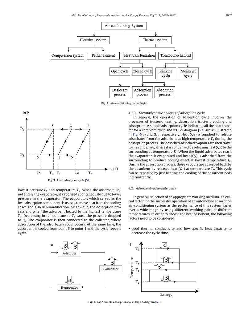
Generally, air-conditioning system can be classified as electri-al system and thermal system, as illustrated in Fig. 2. Electricalystem consists of vapour-compression system and peltier ele-ent, whereas thermal system consists of heat transformation
nd thermo-mechanical process. Heat transformation, which alsonown as sorption system, includes closed and open cycles.losed cycles are referred to absorption and adsorption cycles,
hile open cycles are referred to desiccant cycle. This reviewaper will focus only on the adsorption cycle mainly for automo-ile air-conditioning purpose due to the fact this cycle requiredow regeneration heat compared to absorption cycle. In general,dsorption cycle can be categorized into two main cycles; namely
able 1omparison between vapour-compression system and the adsorption system.
Vapour-compression system
• Mechanical compressor is used to compress the refrigerant vapour betweenthe evaporator and the condenser.
• Mechanical compressor is driven by the shaft powered by the engine.• CFC and HCFC are usually used as refrigerant.• Compressor failure can be due to wear.
Energy Reviews 15 (2011) 2061–2072
intermittent cycle and continuous cycle. Intermittent cycle seemsnot suitable to be employed in automobile application due to thefact that it cannot provide continuous cooling as needed. Thus, acontinuous cycle could be adopted here to generate continuouscooling effect by using two or more adsorbers that operate inter-mittently.
4.1. Adsorption cycle
4.1.1. Basic of adsorptionGenerally, adsorption is a process where molecules of a gas
or liquid contact and adhere to a solid surface. This process isalways exothermic, where heat is liberated. The substrate on whichadsorption take place is called as adsorbent, whereas the materialconcentrated on the surface of the adsorbent is called as adsor-bate. Adsorbents are the matters that contain a lot of minisculeinternal pores as small as nanometres. Adsorption mechanisms canbe categorized into two types; namely physical adsorption andchemical adsorption. Physical adsorption is the type of adsorp-tion in which the forces involved are intermolecular forces or Vander Waals forces. Chemical adsorption, on the other hand, is thetype of adsorption in which the forces involved are covalence orionic forces between the adsorbing molecules and the adsorbent.As covalence or ionic bonding is normally greater than Van derWaals bonding, more heat is liberated when chemical adsorptionoccurred. Besides, the process of physical adsorption is reversible,while chemical adsorption process is irreversible. Typically, anadsorption cycle applied in air-conditioning or refrigeration doesnot use any mechanical energy, but only heat energy from wasteheat, solar or any means of heat. Adsorption unit usually consists ofone or several adsorbers, a condenser, an evaporator and associatedto the heat source. This cycle is basically an intermittent becausecold production proceeds only during part of the cycle if only oneadsorber is utilized. Nevertheless, when more than one adsorberis used, this cycle can be operated out of phase and generate aquasi-continuous cooling effect. For situation where all the energyrequired for heating the adsorber is provided by the heat source,the cycle is called as single effect cycle. Likewise, double effect cyclecan be processed by using two or more adsorbers. In double effectcycles some heat is internally recovered between the adsorbers,which enhance the cycle performance. Various types of adsorp-tion cycles have been studied extensively by Wang [51]. Some ofthe common adsorption cycles are basic cycle, mass recovery cycle,continuous heat recovery cycle, thermal wave cycle, cascade multieffect cycle, and hybrid heating and cooling cycle.
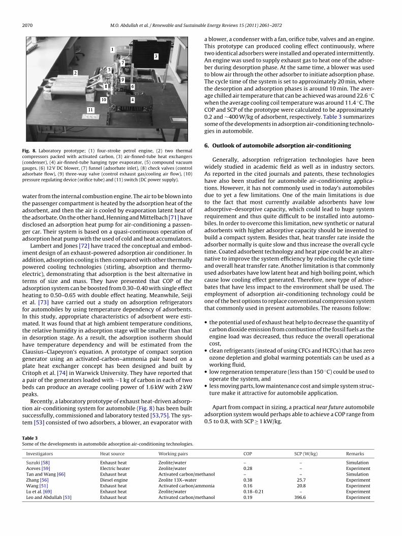
4.1.2. Ideal adsorption cycleBasically, an ideal adsorption cycle can be well represented by
using Clapeyron diagram [52], as shown in Fig. 3. At point 1, theideal adsorption cycle start under low pressure P5 and low temper-ature T1. The adsorbent and adsorbate is then heated from point 1
to point 2 at higher pressure P3. Continue heating of the adsorbentand adsorbate from point 2 to point 4 will cause some adsor-bate vapour to be desorbed from the adsorber and then condensedthrough a condenser at point 3. After that, the adsorbate in liq-uid form is flowed into the evaporator from point 3 to point 5 atAdsorption system
• Thermal compressor is used to compress the adsorbate by adsorbing anddesorbing adsorbate vapour.• Waste heat from the automobile engine can be utilized to operate the system.• Water, methanol or other alternative clean refrigerant can be used.• Less moving parts.
M.O. Abdullah et al. / Renewable and Sustainable Energy Reviews 15 (2011) 2061–2072 2067
Fig. 2. Air-conditionin
luphscTtaaa
Fig. 3. Ideal adsorption cycle [52].
owest pressure P5 and temperature T5. When the adsorbate liq-id enters the evaporator, it vaporized spontaneously due to lowerressure in the evaporator. The evaporator, which serves as theeat absorption component, is uses to remove heat from the coolingpace and also dehumidification. Meanwhile, the desorption pro-ess end when the adsorbent heated to the highest temperature
4. Decreasing in temperature to T6 cause the pressure droppedo P5. The evaporator is then connected to the collector, wheredsorption of the adsorbate vapour occurs. At the same time, thedsorbent is cooled from point 6 to point 1 and the cycle repeatsgain.Fig. 4. (a) A simple adsorption c
g technologies.
4.1.3. Thermodynamic analysis of adsorption cycleIn general, the operation of adsorption cycle involves the
processes of isosteric heating, desorption, isosteric cooling andadsorption. A simple adsorption cycle indicating all the heat trans-fer for a complete cycle and its T-S diagram [53] are as illustratedin Fig. 4(a) and (b), respectively. Heat (Qd) is supplied to releaseadsorbates from the adsorbent at high temperature Td during thedesorption process. The desorbed adsorbate vapours are then travelto the condenser, where it is condensed by releasing heat (Qc) to thesurrounding at temperature Tc. When the liquid adsorbates reachthe evaporator, it evaporated and heat (Qe) is adsorbed from thesurrounding to produce cooling effect at lowest temperature Te.During the adsorption process, these vapours are adsorbed back bythe adsorbent by released heat (Qa) at temperature Ta. This cyclecan be repeated by just heating and cooling of the adsorbent bedsintermittently.
4.2. Adsorbent–adsorbate pairs
In general, selection of an appropriate working medium is a cru-cial factor for the successful operation of an automobile adsorptionair-conditioning system as the performance of this system variesover a wide range by using different working pairs at differenttemperatures. In order to choose the best adsorbent, the following
factors need to be considered:• good thermal conductivity and low specific heat capacity todecrease the cycle time,
ycle; (b) T-S diagram [53].

2068 M.O. Abdullah et al. / Renewable and Sustainable Energy Reviews 15 (2011) 2061–2072
Table 2Some adsorbent–adsorbate pair and their heat of adsorption [54].
Adsorbent Adsorbate Heat of adsorption(kJ/kg)
Silica gelWater 2800Methyl alcohol 1000–1500
Zeolite (variousgrades)
Water 3300–4200Carbon dioxide 800–1000Methanol 2300–2600Ammonia 4000–6000
Activated alumina Water 3000
Activated carbon
Ethene 1000–2000Ethanol 1200–1400Methanol 1800–2000Water 2300–2600
•
••
a
••••
tmczmw
4
bmtp
C
wad
a
S
w
ccs
Ammonia 2000–2700
Calcium chloride Methanol –
high adsorption and desorption capacity to achieve higher cool-ing effect,no chemical reaction with the adsorbate used, andwidely available and also low cost.
While the preferable adsorbate should have the following desir-ble thermodynamics and heat transfer properties:
high latent heat per unit volume to increase the cooling effect,high thermal conductivity to decrease the cycle time,chemically stable within the working temperature range, andnon-toxic and non-corrosive.
Suitable adsorbate must be choosing carefully in ordero achieve high performance of the adsorption system. The
ost common adsorbate–adsorbent pairs utilized are activatedarbon–methanol, activated carbon–ammonia, zeolite–water,eolite–organic refrigerants, silica gel–water, salts–ammonia,etal–hydrogen, etc. Some of the common working pairs togetherith their heat of adsorption [54] are as listed in Table 2.
.3. Performance analysis
The performance of the adsorption system is usually assessedy using two performance factors; namely coefficient of perfor-ance (COP) and specific cooling power (SCP). COP is defines as
he amount of cooling produced by the adsorption cooling systemer unit heat supplied [55,56] as given below:
OP = Qe
Qd(1)
here Qe is the quantity of heat transferred through the evaporator,nd Qd is the quantity of heat adsorbed by the adsorber duringesorption phase.
While SCP is defined as the ratio between the cooling productionnd the cycle time per unit of adsorbent weight, as given follow:
CP = Qe
tcma(2)
here tc is the cycle time, and ma is mass of the adsorbent.
Since SCP is correlates to both the mass of adsorbent and theooling power, it determines the size of the system. For a smallooling load, higher SCP values indicate the compactness of theystem.
Fig. 5. Schematic diagram of adsorption air-conditioning system for electric vehicle[59].
5. Application of adsorption technologies in automobileair-conditioning
Duran [57] has disclosed an apparatus employed chemisorp-tions principle as a vehicle air-conditioner. Chemisorptions arethe type of adsorption in which the forces involved are covalenceor ionic forces between the adsorbing molecules and the adsor-bent. The drawback of such system is that very high temperatureis needed during regeneration process to release the adsorbate. Apreliminary study has been carried out by Suzuki [58] to elucidatethe technological limits associated with the application of adsorp-tion cooling systems to automobiles. The working pair used in thestudy was zeolite-water and exhaust heat as the thermal energyinput to the system. Suzuki study showed that a cooling capacityof 2800 W/kg per one unit of adsorbent bed is expected if the UA of100 kW/(mK) could be achieved and adsorption–desorption cyclesof 60–60 s could be adopted. However, the author just did somesimulations study and no experimental work being carried out toverify his claimed.
Aceves [59] has carried out an experimental analysis of theapplicability of an adsorption system for electric vehicle air con-ditioning, as shown in Fig. 5. The COP of the system, with zeoliteand water as a working pair, was approximately 0.28. His stud-ies indicated that conventional compression air conditioners weresuperior to adsorption systems due to their higher COP and aremore compact. The drawback of using zeolite–water as a workingpair is that a very low operating pressure is needed. Meanwhile,Bhatti et al. [60] have disclosed the use of zeolite to dehumidify theair by using desiccant wheel. This wheel consists of two sections;the first section dehumidified the air before supply to the evapora-tor of the conventional compression air-conditioning system whileregeneration of the saturated zeolite by using heated air is takeplace in another section simultaneously. Unfortunately, these sys-tems are not currently used because the wheel is too large to beinstalled in a typical automobile.
Sato et al. [61] have presented a multiple-stage adsorption air-conditioning system for vehicle. They also reveal that two or moreadsorbers are utilized during adsorption and regeneration pro-cesses, respectively. Although the efficiency of the multiple-stageadsorption system improved, the size of the system also increasedand thus adds complexity to its control system. Denniston [62]has disclosed dehumidification systems to dehumidification andhumidification of air prior to its entry into the vehicle interior.In addition, he also disclosed various bed configurations to dehu-midify the air and regeneration the bed by utilizing heat from theengine. The application of electric heating element to regeneratethe adsorbent was disclosed by Kirol and Rockenfeller [63] and
Tanaka et al. [64]. Although their system may be effective dur-ing regeneration process, the utilization of electric heating elementadds complexity to the adsorption system. This is because the heat-ing element must be properly mounted to the adsorbent bed in
M.O. Abdullah et al. / Renewable and Sustainable Energy Reviews 15 (2011) 2061–2072 2069
for bu
ot
prcfceWiefititatwtr
dpitapaitdeevfutvcfctttt
refrigerator is used to control the temperature of the air to be blowninto a passenger compartment of the vehicle. The adsorbent gen-erates adsorption heat when the adsorbent adsorbs the adsorbate,and desorbs the adsorbate when the adsorbent is heated by coolant
Fig. 6. Schematic diagram of adsorption air conditioner
rder to create a better heat transfer between the adsorbent andhe heating element. Besides, a proper wiring is needed.
Li and Ling [65] have presented a numerical study of the dynamicerformance of an adsorption cooling for automobile waste heatecovery. It was found that the SCP is more sensitive to parameterhanges than the COP and by improving the overall heat trans-er coefficient is the most effective way to increase SCP. Structuralharacteristics of the adsorption air conditioning system driven byxhausted gas in automobiles have been presented by Tan andang [66]. They found that the heat pipe effect is apparent in
sosteric heating and isosteric cooling stages, which can greatlynhance the heat transfer effectiveness. They also discussed severalactors that influence the performance of the system, such as work-ng conditions and physical characteristics of adsorbent. Besides,hey concluded that by enhancing the effective thermal conductiv-ty of the absorber and decreasing the contact resistance are the keyechnologies in this system. Meanwhile, Zhang [56] has describedn experimental intermittent adsorption cooling system driven byhe waste heat of a diesel engine. Zeolite 13X–water is used as theorking pair and a finned double-tube heat exchanger is used as
he adsorber. The COP and SCP of the system are 0.38 and 25.7 W/kg,espectively.
Wang [51] has reported an adsorption air conditioning for a busriven by using waste heat from exhausted gases. The workingair for this system is activated carbon-ammonia with the cool-
ng power of 2.58 kW and COP of 0.16. The design configuration ofhe overall system was shown in Fig. 6, which consisted of twodsorbers (Adsorber A and Adsorber B). The activated carbon isressurized to the density of about 900 kg/m in order to fill moredsorbent into the adsorber. The total weight of the two adsorberss about 248 kg and occupied about 1.0 m2. The disadvantages ofhis system are it is bulky and heavy. Nagatomo et al. [67] haveescribed a vehicular adsorption type air-conditioner capable ofnhancing the heat radiation performance of an outdoor unit andnhancing the cooling capacity. The outdoor unit is installed on aehicle roof top. Much more fresh air not affected by exhaust heatrom an engine or the ground heat is allowed to flow in the outdoornit. Thus, the temperature of liquid refrigerant passing throughhe outdoor unit can be dropped and the cooling capacity of theehicular adsorption type air-conditioner can be enhanced. As aontinuation part, Nagatomo et al. [68] have disclosed a methodor saving the water feeding power based on the temperature of
ooling liquid and heat transfer fluid in the vehicular adsorptionype air-conditioner. The air-conditioner comprises a fourth pumpo allow cooling water heated by an engine to flow into a desorp-ion step of an adsorber. First and second pumps drive second heatransfer fluid cooled by an outdoor unit to flow into an adsorp-ses driven by the waste heat from exhausted gases [51].
tion step of the adsorber. A third pump drive third heating transferfluid cooled by the evaporator to flow into an indoor unit. Watertemperature sensors detect temperature of the second heat trans-fer medium and the third heat transfer fluid. The first to fourthpumps are controlled to adjust the water feeding power based ontemperature information detected by the water temperature sen-sors. However, the utilization of pumps in vehicular adsorption typeair-conditioner adds the complexity of the system and also causedsystem malfunction due to pump failure.
Experimental studies on the practical performance of an adsorp-tion air conditioning system powered by exhausted heat froma diesel locomotive have been presented by Lu et al. [69]. Thesystem (Fig. 7) was incorporated with one adsorbent bed and uti-lizes zeolite-water as a working pair to provide chilled water forconditioning the air in the driver’s cab of the locomotive. Theirexperimental results showed that the adsorption system is techni-cally feasible and can be applied for space air conditioning. Undertypical running conditions, the average refrigeration power rangingfrom 3.0 to 4.2 kW has been obtained. However, this system maynot suitable to be mounted on automobile due to its size and alsohigh temperature is required during regeneration process. Mean-while, Inoue et al. [70] have described a system, which used coolingwater from internal combustion engine that includes a compressiverefrigerator and an adsorption type refrigerator. The compressive
Fig. 7. Schematic diagram of locomotive driver cabin air-conditioner [69].
2070 M.O. Abdullah et al. / Renewable and Sustainable
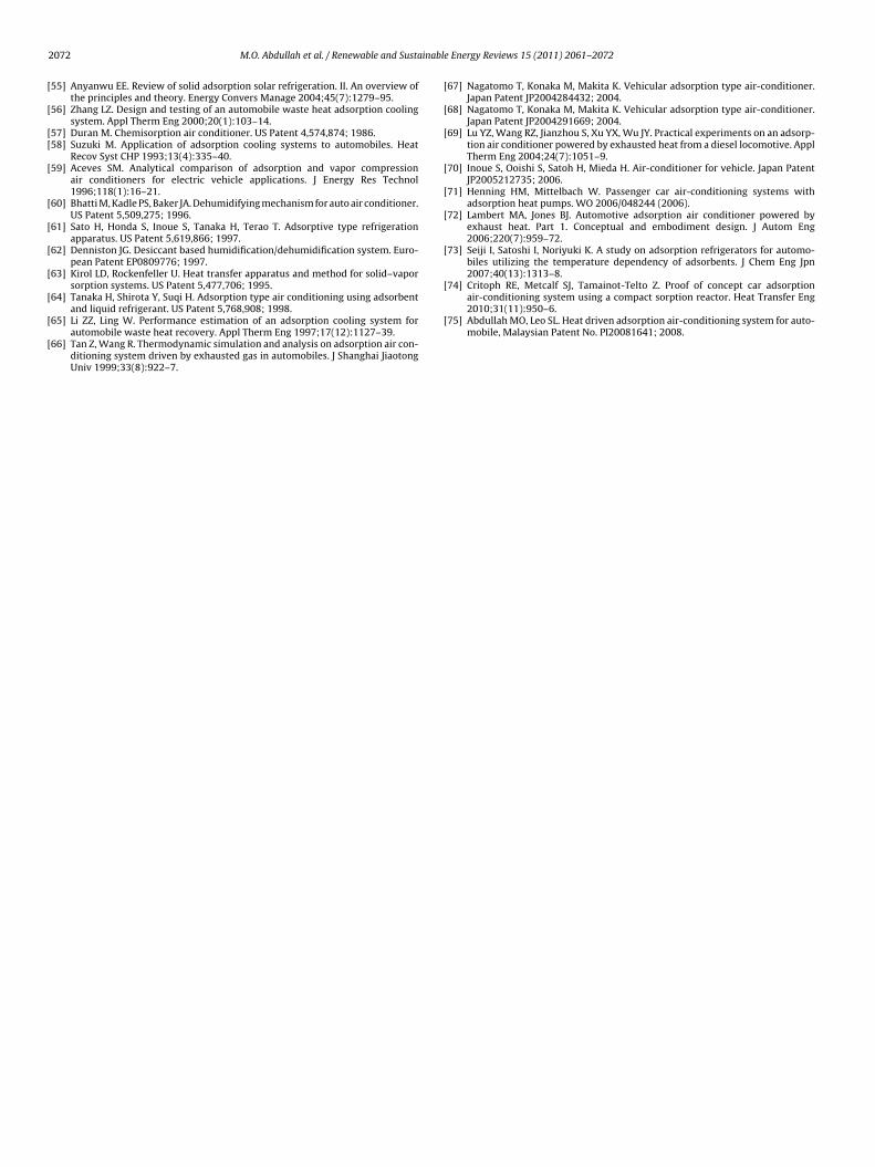
Fig. 8. Laboratory prototype; (1) four-stroke petrol engine, (2) two thermalcompressors packed with activated carbon, (3) air-finned-tube heat exchangers(gap
wtatdga
iapetahefImtihCgpCabp
tst
TS
condenser), (4) air-finned-tube hanging type evaporator, (5) compound vacuumauges, (6) 12 V DC blower, (7) funnel (adsorbate inlet), (8) check valves (controldsorbate flow), (9) three-way valve (control exhaust gas/cooling air flow), (10)ressure regulating device (orifice tube) and (11) switch (DC power supply).
ater from the internal combustion engine. The air to be blown intohe passenger compartment is heated by the adsorption heat of thedsorbent, and then the air is cooled by evaporation latent heat ofhe adsorbate. On the other hand, Henning and Mittelbach [71] haveisclosed an adsorption heat pump for air-conditioning a passen-er car. Their system is based on a quasi-continuous operation ofdsorption heat pump with the used of cold and heat accumulators.
Lambert and Jones [72] have traced the conceptual and embod-ment design of an exhaust-powered adsorption air conditioner. Inddition, adsorption cooling is then compared with other thermallyowered cooling technologies (stirling, absorption and thermo-lectric), demonstrating that adsorption is the best alternative inerms of size and mass. They have presented that COP of thedsorption system can be boosted from 0.30–0.40 with single effecteating to 0.50–0.65 with double effect heating. Meanwhile, Seijit al. [73] have carried out a study on adsorption refrigeratorsor automobiles by using temperature dependency of adsorbents.n this study, appropriate characteristics of adsorbent were esti-
ated. It was found that at high ambient temperature conditions,he relative humidity in adsorption stage will be smaller than thatn desorption stage. As a result, the adsorption isotherm shouldave temperature dependency and will be estimated from thelausius–Clapeyron’s equation. A prototype of compact sorptionenerator using an activated-carbon–ammonia pair based on alate heat exchanger concept has been designed and built byritoph et al. [74] in Warwick University. They have reported thatpair of the generators loaded with ∼1 kg of carbon in each of twoeds can produce an average cooling power of 1.6 kW with 2 kW
eaks.Recently, a laboratory prototype of exhaust heat-driven adsorp-ion air-conditioning system for automobile (Fig. 8) has been builtuccessfully, commissioned and laboratory tested [53,75]. The sys-em [53] consisted of two adsorbers, a blower, an evaporator with
able 3ome of the developments in automobile adsorption air-conditioning technologies.
Investigators Heat source Working pairs
Suzuki [58] Exhaust heat Zeolite/waterAceves [59] Electric heater Zeolite/waterTan and Wang [66] Exhaust heat Activated carbon/methZhang [56] Diesel engine Zeolite 13X–waterWang [51] Exhaust heat Activated carbon/ammLu et al. [69] Exhaust heat Zeolite/waterLeo and Abdullah [53] Exhaust heat Activated carbon/meth
Energy Reviews 15 (2011) 2061–2072
a blower, a condenser with a fan, orifice tube, valves and an engine.This prototype can produced cooling effect continuously, wheretwo identical adsorbers were installed and operated intermittently.An engine was used to supply exhaust gas to heat one of the adsor-ber during desorption phase. At the same time, a blower was usedto blow air through the other adsorber to initiate adsorption phase.The cycle time of the system is set to approximately 20 min, wherethe desorption and adsorption phases is around 10 min. The aver-age chilled air temperature that can be achieved was around 22.6 ◦Cwhen the average cooling coil temperature was around 11.4 ◦C. TheCOP and SCP of the prototype were calculated to be approximately0.2 and ∼400 W/kg of adsorbent, respectively. Table 3 summarizessome of the developments in adsorption air-conditioning technolo-gies in automobile.
6. Outlook of automobile adsorption air-conditioning
Generally, adsorption refrigeration technologies have beenwidely studied in academic field as well as in industry sectors.As reported in the cited journals and patents, these technologieshave also been studied for automobile air-conditioning applica-tions. However, it has not commonly used in today’s automobilesdue to yet a few limitations. One of the main limitations is dueto the fact that most currently available adsorbents have lowadsorptive–desorptive capacity, which could lead to huge systemrequirement and thus quite difficult to be installed into automo-biles. In order to overcome this limitation, new synthetic or naturaladsorbents with higher adsorptive capacity should be invented tobuild a compact system. Besides that, heat transfer rate inside theadsorber normally is quite slow and thus increase the overall cycletime. Coated adsorbent technology and heat pipe could be an alter-native to improve the system efficiency by reducing the cycle timeand overall heat transfer rate. Another limitation is that commonlyused adsorbates have low latent heat and high boiling point, whichcause low cooling effect generated. Therefore, new type of adsor-bates that have less impact to the environment shall be used. Theemployment of adsorption air-conditioning technology could beone of the best options to replace conventional compression systemthat commonly used in present automobiles. The reasons follow:
• the potential used of exhaust heat help to decrease the quantity ofcarbon dioxide emission from combustion of the fossil fuels as theengine load was decreased, thus reduce the overall operationalcost,
• clean refrigerants (instead of using CFCs and HCFCs) that has zeroozone depletion and global warming potentials can be used as aworking fluid,
• low regeneration temperature (less than 150 ◦C) could be used tooperate the system, and
• less moving parts, low maintenance cost and simple system struc-
ture make it attractive for automobile application.Apart from compact in sizing, a practical near future automobileadsorption system would perhaps able to achieve a COP range from0.5 to 0.8, with SCP ≥ 1 kW/kg.
COP SCP (W/kg) Remarks
– – Simulation0.28 – Experiment
anol – – Simulation0.38 25.7 Experiment
onia 0.16 20.8 Experiment0.18–0.21 – Experiment
anol 0.19 396.6 Experiment

inable
7
tbpoaoAblapap
A
SPlMtt
R
[
[
[
[
[
[
[
[
[
[
[
[
[
[
[
[
[
[
[
[
[
[
[
[
[
[
[
[
[
[
[
[
[
[
[
[
[
[
[
[
[
[
[
M.O. Abdullah et al. / Renewable and Susta
. Conclusions
Recent research has shown that new evolvement in adsorptionechnology has a promising potential to be adopted in automo-ile air-conditioning purpose. The technology is expected to beractical when further improvements are done to overcome somef the limitations mentioned above. Using clean refrigerants indsorption air-conditioning systems will reduces the productionf unwanted ozone depleting substances, such as CFCs and HCFCs.s such, adsorption air-conditioning system for automobile shoulde seriously looked into. Besides it being environmentally friendly,
ow maintenance cost could be expected. By implementing thedsorption air-conditioning system powered by waste heat mayrovide a comfort for the driver and/or passengers by lowering their temperature level and also for air ventilation during driving orarking.
cknowledgements
The present study was supported by the Universiti Malaysiaarawak’s Special Project Grant No. DI/04/2007/(04) and Danaenyelidikan Khas UNIMAS-DPK/01/2010. The third author wouldike to thank the Ministry of Science, Technology and Innovation of
alaysia for the MOSTI fellowship award. The authors would likeo thank all staff for their continuous encouragements throughouthis project.
eferences
[1] Dieng AO, Wang RZ. Literature review on solar adsorption technologies forice-making and air conditioning purposes and recent developments in solartechnology. Renew Sust Energy Rev 2001;5(4):313–42.
[2] Critoph RE. An ammonia carbon solar refrigerator for vaccine cooling. RenewEnergy 1994;5:502–8.
[3] Boubakri A, Guilleminot JJ, Meunier F. Adsorptive solar powered ice maker:experiments and model. Sol Energy 2000;69(3):249–63.
[4] Saha BB, Akisawa A, Kashiwagi T. Solar/waste heat driven two-stage adsorptionchiller: the prototype. Renew Energy 2001;23(1):93–101.
[5] Lu YZ, Wang RZ, Zhang M, Jiangzhou S. Adsorption cold storage system withzeolite–water working pair used for locomotive air conditioning. Energy Con-vers Manage 2003;44(10):1733–43.
[6] Abdullah MO, Ngui JL, Hamid KA, Leo SL, Tie SH. Cooling performance of acombined solar thermoelectric-adsorption cooling system: an experimentalstudy. Energy Fuels 2009;23:5677–83.
[7] Al-Ghouti MA, Yousef I, Ahmad R, Ghrair AM, Al-Maaitah AA. Characteriza-tion of diethyl ether adsorption on activated carbon using a novel adsorptionrefrigerator. Chem Eng J 2010;162(1):234–41.
[8] Banker ND, Prasad M, Dutta P, Srinivasan K. Development and transient per-formance results of a single stage activated carbon–HFC 134a closed cycleadsorption cooling system. Appl Therm Eng 2010;30(10):1126–32.
[9] El-Sharkawy II, Saha BB, Koyama S, He J, Ng KC, Yap C. Experimental investi-gation on activated carbon–ethanol pair for solar powered adsorption coolingapplications. Int J Refrig 2008;31(8):1407–13.
10] Zhao H, Zhang M, Zhenyan L, Yanling L, Xiaodong M. Mechanical andexperimental study on freeze proof solar powered adsorption coolingtube using active carbon/methanol working pair. Energy Convers Manage2008;49(8):2434–8.
11] Arami-Niya A, Daud WMAW, Mjalli FS. Using granular activated carbon pre-pared from oil palm shell by ZnCl2 and physical activation for methaneadsorption. J Anal Appl Pyrol 2010;89(2):197–203.
12] Owlad M, Aroua MK, Daud WMAW. Hexavalent chromium adsorption onimpregnated palm shell activated carbon with polyethyleneimine. BioresourTechnol 2010;101(14):5098–103.
13] Issabayeva G, Aroua MK, Sulaiman NM. Study on palm shell activated carbonadsorption capacity to remove copper ions from aqueous solutions. Desalina-tion 2010;262(1–3):94–8.
14] Hamad BK, Noor AM, Afida AR, Mohd Asri MN. High removal of 4-chloroguaiacolby high surface area of oil palm shell-activated carbon activated with NaOHfrom aqueous solution. Desalination 2010;257(1–3):1–7.
15] Lua AC, Jia Q. Adsorption of phenol by oil-palm-shell activated carbons in a
fixed bed. Chem Eng J 2009;150(2–3):455–61.16] Lim YN, Shaaban MG, Yin CY. Treatment of landfill leachate using palm shell-activated carbon column: axial dispersion modeling and treatment profile.Chem Eng J 2009;146(1):86–9.
17] IUPAC. IUPAC manual of symbols and terminology. Pure Appl Chem1972;31:587.
[
[
Energy Reviews 15 (2011) 2061–2072 2071
18] Wu FC, Tseng RL, Hu CC. Comparisons of pore properties and adsorption per-formance of KOH-activated and steam-activated carbons. Micropor MesoporMater 2005;80:95–106.
19] Sudaryanto Y, Hartono SB, Irawaty W, Hindarso H, Ismadji S. High surface areaactivated carbon prepared from cassava peel by chemical activation. BioresourTechnol 2006;97:734–9.
20] El-Hendawy ANA. Surface and adsorptive properties of carbons prepared frombiomass. Appl Surf Sci 2005;252:287–95.
21] Yehaskel A. Activated carbon: manufacture regeneration. USA: Noyes Data Cor-poration; 1978.
22] Allen SJ, Koumanova B. Decolourisation of water/wastewater using adsorption(review). J Univ Chem Technol Metall 2005;40:175–92.
23] Girgis BS, El-Hendawy ANA. Porosity development in activated carbonsobtained from date pits under chemical activation with phosphoric acid. Micro-por Mesopor Mater 2002;52:105–17.
24] Ioannidou O, Zabaniotou A. Agricultural residues as precursors for activatedcarbon production: a review. Renew Sust Energy Rev 2007;11:1966–2005.
25] Dias JM, Alvim-Ferraz MCM, Almeida MF, Rivera-Utrilla J, Sanchez-Polo M.Waste materials for activated carbon preparation and its use in aqueous-phasetreatment: a review. J Environ Manage 2007;85:833–46.
26] Hassan MA, Yacob S. Biomass utilization in Malaysia: current status of conver-sion of biomass into bioproducts; 2007.
27] Husain Z, Zainal ZA, Abdullah MZ. Analysis of biomass-residue-based cogener-ation system in palm oil mills. Biomass Bioenerg 2003;24:117–24.
28] Guo J, Lua AC. Characterization of adsorbent prepared from oil-palm shell byCO2 activation for removal of gaseous pollutants. Mater Lett 2002;55:334–9.
29] Guo J, Lua AC. Textural and chemical properties of adsorbent prepared frompalm shell by phosphoric acid activation. Mater Chem Phys 2003;80:114–9.
30] Daud WMAW, Ali WSW. Comparison on pore development of activated carbonproduced from palm shell and coconut shell. Bioresour Technol 2004;93:63–9.
31] Lua AC, Lau FY, Guo J. Influence of pyrolysis conditions on pore developmentof oil-palm-shell activated carbons. J Anal Appl Pyrol 2006;76:96–102.
32] Adinata D, Wan Daud WMA, Aroua MK. Preparation and characterization ofactivated carbon from palm shell by chemical activation with K2CO3. BioresourTechnol 2007;98:145–9.
33] Kamishita M, Mahajan OP, Walker PL. Effect of carbon deposition on porosityand reactivity of lignite char. Fuel 1977;56:444–50.
34] Rahman IA, Saad B B. Utilization of guava seeds as a source of activated car-bon for removal of methylene blue from aqueous solution. Malays J Chem2003;5:8–14.
35] Turmuzi M, Daud WRW, Tasirin SM, Takriff MS, Iyuke SE. Production of acti-vated carbon from candlenut shell by CO2 activation. Carbon 2004;42:453–5.
36] Yang RT. Adsorbents: fundamentals and applications. New York: John Wileyand Sons Inc.; 2003.
37] Guo Y, Rockstraw DA. Physicochemical properties of carbons prepared frompecan shell by phosphoric acid activation. Bioresour Technol 2007;98:1513–21.
38] Gregg SJ, Sing KSW. Adsorption surface area and porosity. London: AcademicPress; 1982.
39] Hassler JW. Purification with activated carbon: industrial commercial environ-mental. New York: Chemical Publishing Co Inc.; 1974.
40] Savova D, Apak E, Ekinci F, Yardim F, Petrov N, Budinova T. Biomass conversionto carbon adsorbents and gas. Biomass Bioenerg 2001;21:133–42.
41] Girgis BS, Yunis SS, Soliman AM. Characteristics of activated carbon from peanuthulls in relation to conditions of preparation. Mater Lett 2002;57:164–72.
42] Eckenfelder WW. Industrial water pollution control. U.S.A.: McGraw-Hill Com-panies Inc.; 2000.
43] Yang T, Lua AC. Characteristics of activated carbons prepared from pistachio-nut shells by physical activation. J Colloid Interface Sci 2003;267:408–17.
44] Prahas D, Kartika Y, Indraswati N, Ismadji S. Activated carbon from jackfruitpeel waste by H3PO4 chemical activation: pore structure and surface chemistrycharacterization. Chem Eng J 2008;140:32–42.
45] Ahmedna M, Marshall WE, Rao RM. Production of granular activated carbonsfrom select agricultural by-products and evaluation of their physical, chemicaland adsorption properties. Bioresour Technol 2000;71:113–23.
46] Aygün A, Yenisoy-Karakas S, Duman I. Production of granular activated carbonfrom fruit stones and nutshells and evaluation of their physical, chemical andadsorption properties. Micropor Mesopor Mater 2003;66:189–95.
47] Mattson JS, Mark HB. Activated carbon: surface chemistry and adsorption fromsolution. New York: Marcell Dekker Inc.; 1971.
48] Moreno-Castilla C. Adsorption of organic molecules from aqueous solutions oncarbon materials. Carbon 2004;42:83–94.
49] Senthilkumaar S, Varadarajan PR, Porkodi K, Subbhuraam CV. Adsorption ofmethylene blue onto jute fiber carbon: kinetics and equilibrium studies. J Col-loid Interface Sci 2005;284:78–82.
50] Vadivelan V, Kumar KV. Equilibrium, kinetics, mechanism, and process designfor the sorption of methylene blue onto rice husk. J Colloid Interface Sci2005;286:90–100.
51] Wang RZ. Adsorption refrigeration research in Shanghai Jiao Tong University.Renew Sust Energy Rev 2001;5(1):1–37.
52] Ruthven DM. Principles of adsorption and adsorption processes. New York:
Wiley; 1984.53] Leo SL, Abdullah MO. Experimental study of an automobile exhaust heat-drivenadsorption air-conditioning laboratory prototype by using palm activatedcarbon–methanol. HVAC&R Res 2010;16(2):221–31.
54] Sumathy K, Yeung KH, Yong L. Technology development in solar adsorptionrefrigeration systems. Prog Energy Combust Sci 2003;29(4):301–27.
2 inable
[
[
[[
[
[
[
[
[
[
[
[
[
[
[
[
[
[
[
2007;40(13):1313–8.[74] Critoph RE, Metcalf SJ, Tamainot-Telto Z. Proof of concept car adsorption
air-conditioning system using a compact sorption reactor. Heat Transfer Eng
072 M.O. Abdullah et al. / Renewable and Susta
55] Anyanwu EE. Review of solid adsorption solar refrigeration. II. An overview ofthe principles and theory. Energy Convers Manage 2004;45(7):1279–95.
56] Zhang LZ. Design and testing of an automobile waste heat adsorption coolingsystem. Appl Therm Eng 2000;20(1):103–14.
57] Duran M. Chemisorption air conditioner. US Patent 4,574,874; 1986.58] Suzuki M. Application of adsorption cooling systems to automobiles. Heat
Recov Syst CHP 1993;13(4):335–40.59] Aceves SM. Analytical comparison of adsorption and vapor compression
air conditioners for electric vehicle applications. J Energy Res Technol1996;118(1):16–21.
60] Bhatti M, Kadle PS, Baker JA. Dehumidifying mechanism for auto air conditioner.US Patent 5,509,275; 1996.
61] Sato H, Honda S, Inoue S, Tanaka H, Terao T. Adsorptive type refrigerationapparatus. US Patent 5,619,866; 1997.
62] Denniston JG. Desiccant based humidification/dehumidification system. Euro-pean Patent EP0809776; 1997.
63] Kirol LD, Rockenfeller U. Heat transfer apparatus and method for solid–vaporsorption systems. US Patent 5,477,706; 1995.
64] Tanaka H, Shirota Y, Suqi H. Adsorption type air conditioning using adsorbent
and liquid refrigerant. US Patent 5,768,908; 1998.65] Li ZZ, Ling W. Performance estimation of an adsorption cooling system forautomobile waste heat recovery. Appl Therm Eng 1997;17(12):1127–39.
66] Tan Z, Wang R. Thermodynamic simulation and analysis on adsorption air con-ditioning system driven by exhausted gas in automobiles. J Shanghai JiaotongUniv 1999;33(8):922–7.
[
Energy Reviews 15 (2011) 2061–2072
67] Nagatomo T, Konaka M, Makita K. Vehicular adsorption type air-conditioner.Japan Patent JP2004284432; 2004.
68] Nagatomo T, Konaka M, Makita K. Vehicular adsorption type air-conditioner.Japan Patent JP2004291669; 2004.
69] Lu YZ, Wang RZ, Jianzhou S, Xu YX, Wu JY. Practical experiments on an adsorp-tion air conditioner powered by exhausted heat from a diesel locomotive. ApplTherm Eng 2004;24(7):1051–9.
70] Inoue S, Ooishi S, Satoh H, Mieda H. Air-conditioner for vehicle. Japan PatentJP2005212735; 2006.
71] Henning HM, Mittelbach W. Passenger car air-conditioning systems withadsorption heat pumps. WO 2006/048244 (2006).
72] Lambert MA, Jones BJ. Automotive adsorption air conditioner powered byexhaust heat. Part 1. Conceptual and embodiment design. J Autom Eng2006;220(7):959–72.
73] Seiji I, Satoshi I, Noriyuki K. A study on adsorption refrigerators for automo-biles utilizing the temperature dependency of adsorbents. J Chem Eng Jpn
2010;31(11):950–6.75] Abdullah MO, Leo SL. Heat driven adsorption air-conditioning system for auto-
mobile, Malaysian Patent No. PI20081641; 2008.