Embed Size (px)
Citation preview
ABCD matrix for reflection and refraction ofGaussian light beams at surfaces of hyperboloidof revolution and efficiency computation for laserdiode to single-mode fiber coupling by way of ahyperbolic lens on the fiber tip
Sankar Gangopadhyay and Somenath Sarkar
We report the formulation of an ABCD matrix for reflection and refraction of Gaussian light beams at thesurfaces of the hyperboloid of revolution that separate media of different refractive indices. The analysisincludes an arbitrary angle of incidence and is based on matching the optical phase at the interface.Finally, we deduce expressions for spot sizes and wave-front radii and use them to obtain the ABCDmatrix. Based on the formulated ABCD matrix for refraction under paraxial approximation, we alsoreport a simple theoretical investigation of the coupling efficiency of a laser diode to a single-mode fiberwith a hyperbolic lens formed on its tip. © 1997 Optical Society of America
1. Introduction
Recently much interest has been generated for fabri-cation of hyperbolic microlenses on a fiber tip to max-imize the source to single-mode fiber couplingefficiency.1,2 However, theoretical calculations forcomputing the coupling optics involve cumbersomenumerical integrations3 because there is no ABCDmatrix for hyperbolic lenses. We report the formu-lation of an ABCD matrix for reflection and refractionof a Gaussian laser beam at the surface of a hyper-boloid of revolution that separates media of differentrefractive indices. We use the prescribed ABCD ma-trix for the simple case of refraction of paraxial raysby a hyperbolic interface to study the source to single-mode fiber coupling with a hyperbolic lens on the tipof a fiber. Such a matrix has been reported for el-lipsoidal surfaces at an arbitrary angle of incidence.4We assume4 that the beam diameter is always small
When this research was performed the authors were with theDepartment of Electronic Science, University of Calcutta, 92A.P.C. Road, Calcutta 700009, India. S. Gangopadhyay is nowwith the Department of Physics, Surendranath College, 24-2 M. G.Road, Calcutta 700009, India.
Received 21 October 1996; revised manuscript received 5 May1997.
0003-6935y97y338582-05$10.00y0© 1997 Optical Society of America
8582 APPLIED OPTICS y Vol. 36, No. 33 y 20 November 1997
compared with the radii of curvature of the wavefronts and the optical surface. This led us to con-sider, at most, the quadratic variation of the relevantwave-front parameters along the transverse coordi-nates. In addition, our second assumption restrictsone of the principal axes of the hyperboloidal surfaceto lie in the plane of incidence.
We also prefer4 to derive our analytical resultsbased on matching the transverse phase and ampli-tude variations of incident, reflected, and refractedwaves along the hyperboloidal boundary between twomedia of refractive indices n1 and n2 instead of com-plicated ray-tracing techniques5 or a generalized ap-proach6 that involves a vector Taylor series but lackssuitable examples with respect to the use of formal-ism.
2. Analysis
A. ABCD Matrix for a Hyperboloid of Revolution
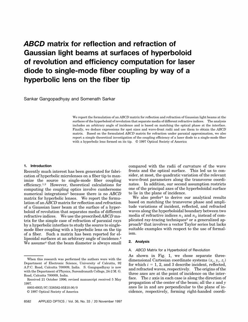
As shown in Fig. 1, we chose separate three-dimensional Cartesian coordinate systems ~xi, yi, zi!for which i 5 1, 2, and 3 describe incident, reflected,and refracted waves, respectively. The origins of thethree axes are at the point of incidence on the inter-face. The z axis in each case is along the direction ofpropagation of the center of the beam; all the x and yaxes lie in and are perpendicular to the plane of in-cidence, respectively, forming right-handed coordi-
nate systems. Here the interface is represented by ahyperboloid of revolution in an X–Y–Z coordinate sys-tem. In Fig. 1, u1 and u2 are, respectively, the anglesof incidence and refraction on the interface that sep-arates media of refractive indices n1 and n2. Be-cause of the principal axis restriction, the interface isconsidered to be a hyperboloid of revolution about theZ axis, with the X–Z plane corresponding to the planeof incidence. In the X–Y–Z coordinate system, thehyperboloid surface is represented by
Z2
a2 2X2 1 Y2
b2 5 1, (1)
where a and b are the lengths of the semi-axes of thehyperboloid of revolution. The transformationequations from XYZ to the incident wave coordinatesare given by
X 5 x1 1 A tan u1, Y 5 y1, Z 5 z1 1 a, (2)
where A 5 b2ya under paraxial approximation. Us-ing Eq. ~2! in Eq. ~1!, the hyperboloidal surface can bedescribed precisely as
~z1 1 a!2
a2 2~x1 1 A tan u1!
2 1 y12
b2 5 1. (3)
Solving for z1 on the interface, accurate to secondorder in transverse variables x1 or y1 and first orderin tan u1, we get
z1 5 x1 tan u1 1 ~x12 1 y1
2!y2A. (4)
Fig. 1. Coordinate systems for a hyperboloid interface and forincident, reflected, and refracted beams.
Now the fields in the three beams are given by
Ui~xi, yi, zi! 5 Ai exp@2jfi~xi, yi, zi!#, i 5 1, 2, 3, (5)
where the phase is given by
fi~xi, yi, zi! 5 kizi 1ki
2 Sxi2
qTi1
yi2
qSiD . (6)
Here, T and S refer to tangential and sagittal planes,respectively, with i 5 1, 2, 3 corresponding to inci-dent, reflected, and refracted beams, respectively.We also have
k1 5 2pn1yl0 5 k2, k3 5 2pn2yl0,
1yqi 5 1yRi 2 jl0ypniwi2. (7)
Here, l0 represents the wavelength in free space andthe complex wave parameter qi combines the wave-front radius of curvature Ri ~positive for a divergingbeam! and the beam radius wi.
Using Eq. ~4! in Eq. ~6!, we can write the phase ofthe incident wave on the interface in terms of x1 andy1 as
f1~x1, y1! 5 k1~x1 tan u1! 1k1x1
2
2 S 1qT1
11AD
1k1y1
2
2 S 1qS1
11AD . (8)
Because the complex phase variation of the wavesmust match exactly on the interface, we obtain
f1~x1, y1! 5 f2~x1, y1! 5 f3~x1, y1!, (9)
and therefrom we derive the important relationsamong different q parameters.
We first consider the refracted wave that can beused to formulate the ABCD matrix.
1. Refracted WaveThe following coordinate transformations are usedfor a refracted wave:
x3 5 x1 cos~u1 2 u2! 1 z1 sin~u1 2 u2!,
y3 5 y1,
z3 5 z1 cos~u1 2 u2! 2 x1 sin~u1 2 u2!. (10)
Now f3~x3, y3, z3! can be expressed in the ~x1, y1, z1!system in terms of x1, y1 on the interface, and usingEqs. ~10! in Eq. ~6! we get
f3~x1, y1! 5 k3$x1@tan u1 cos~u1 2 u2! 2 sin~u1 2 u2!#%
1k3x1
2
2 F 1qT3
1cos~u1 2 u2!
A
1sin 2~u1 2 u2!tan u1
qT3G
1k3y1
2
2 F 1qS3
1cos~u1 2 u2!
A G . (11)
20 November 1997 y Vol. 36, No. 33 y APPLIED OPTICS 8583
Following Eq. ~9! we can equate coefficients of x12 and
y12 in Eqs. ~11! and ~8! to get
1qT3,S3
51
nqT1,S11
1 2 n cos~u1 2 u2!
nA, (12)
where n 5 n2yn1. Using Snell’s law obtained byequating coefficients of x1 in Eqs. ~11! and ~8! andmaking use of a paraxial approximation, we modifiedEq. ~12! as follows:
1qT3,S3
51
nqT1,S11
1 2 n cos u1
nA. (13)
The w and R parameters of the refracted wave arethen given in matrix form as
1wT3,S3
wT3,S3
RT3,S32 5 1 1
1 2 n cos u1
nb2ya
01n21wT1,S1
wT1,S1
RT1,S12 . (14)
We obtained identical ABCD matrices for refractionat the surface of a hyperboloid of revolution at anarbitrary angle of incidence in both the sagittal andtangential planes.
2. Reflected WaveFor a reflected beam, we used the following coordi-nate transformations:
x2 5 2x1 cos 2u1 2 z1 sin 2u1,
y2 5 y1,
z2 5 x1 sin 2u1 2 z1 cos 2u1. (15)
Using Eqs. ~15! and ~6! we obtained phase f2~x1, y1!for a reflected beam on the interface as
f2~x1, y1! 5 k1x1 tan u1 1k1x1
2
2 S 1qT2
2cos 2u1
A D1
k1y12
2 S 1qS2
2cos 2u1
A D . (16)
Now using f1~x1, y1! 5 f2~x1, y1! on the interface, andequating coefficients of x1
2 and y12, we obtain
1qT2,S2
51
qT1,S11
2 cos2 u1
A. (17)
From Eq. ~17! we get spot sizes and wave-front radiithat can be put in matrix form as follows:
1wT2,S2
wT2,S2
RT2,S22 5 1 1
2 cos2 u1
b2ya
0121wT1,S1
wT1,S1
RT1,S12 . (18)
Therefore, in both the tangential and sagittal planes,we obtained identical ABCD matrices for reflectionfrom the surface of a hyperboloid of revolution at anarbitrary angle of incidence.
Our analysis presents a simple, explicit, and intu-itive derivation specific to hyperboloids. One anal-ysis5 contains a description of Gaussian beam
8584 APPLIED OPTICS y Vol. 36, No. 33 y 20 November 1997
propagation through optical systems by tracing com-plex rays, but this abstract approach lacks the for-mulation of a curvature matrix of the interface. It isrelevant to note that the curvature matrix can befound by creating a vector Taylor series expansionabout the point of intersection of the optic axis andthe surface. Another analysis6 that involves appli-cations of such a vector Taylor series is not simpleenough for the system users who prefer conventionaltechniques. We now apply our simple theory to ahyperbolic lensed fiber.
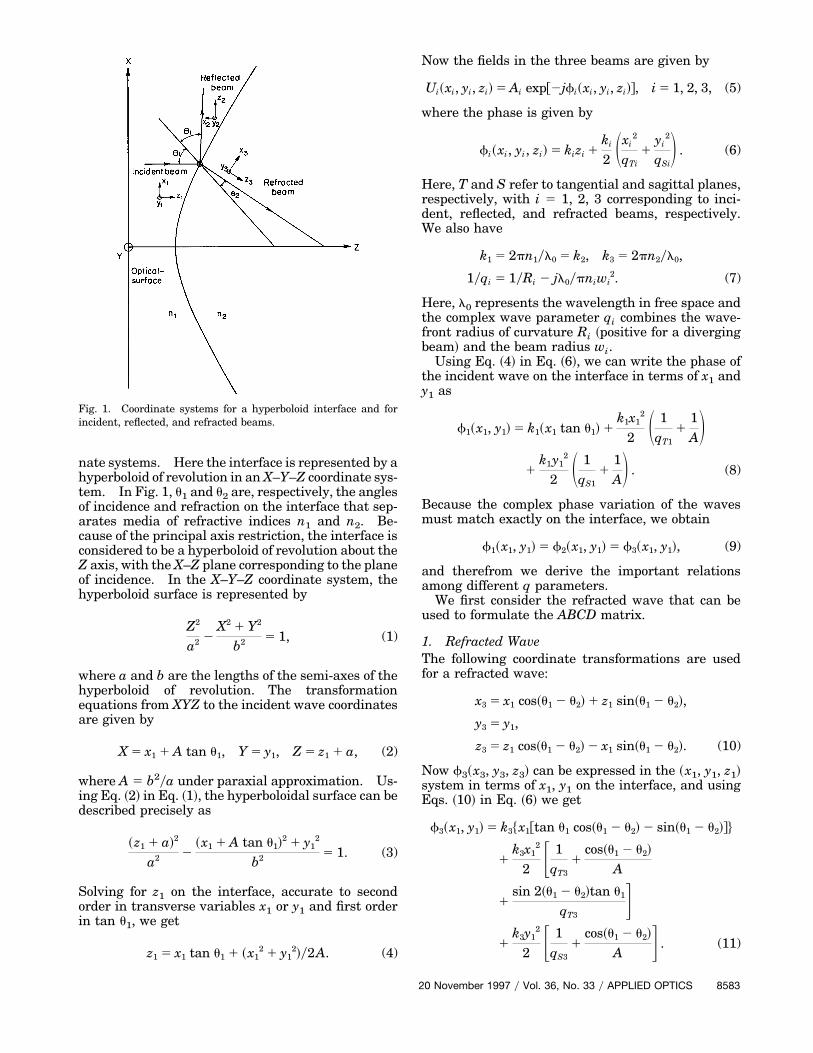
B. Coupling Efficiency
The coupling scheme that we studied is shown in Fig.2. The hyperbolic lens on the tip of the fiber shouldmatch the modes of the laser diode and the single-mode fiber. The laser diode is known to emit opticalbeams that possess an elliptical intensity profile.The intensity profiles are approximated by a Gauss-ian function of spot sizes w1x and w1y along two mu-tually perpendicular directions, one perpendicularand the other parallel to the junction planes. Thelaser field cu at a distance u from the lens surface canbe given by7
cu 5 exp@2~x2yw1x2 1 y2yw1y
2!#
3 exp@2~ jk1!~x2 1 y2!y2R1#. (19)
The fundamental mode in the single-mode circularcore fiber is also represented by a Gaussian function7:
cf 5 exp@2~x2 1 y2!ywf2#, (20)
where the spot size wf can be approximated8 as
wf 5 r~0.65 1 1.619yv1.5 1 2.879yv6!, (21)
where r is the core radius and v is the normalizedfrequency given by k0r~nco
2 2 ncl2!1y2, where nco and
ncl are the refractive indices of the core and the clad-ding, respectively, and k0 is the free space wave num-ber.
The lens-transformed laser field cv on fiber plane 2is given by
cv 5 exp@2~x2yw3x2 1 y2yw3y
2!#
3 exp@~2jk3!~x2yR3x 1 y2yR3y!y2#, (22)
Fig. 2. Geometry of an optical beam emitted from input plane 1 ofa laser diode ~L.D.! and refracted through a hyperbolic lens ontoplane 2, which is the end face of a single-mode fiber ~S.M.F.!.
where w3x and w3y represent transformed spot sizesand R3x and R3y are transformed radii of curvature inthe x and y directions, respectively. Again, we showbelow how w3x,3y and R3x,3y can be found in terms ofw1x,1y and R1 with the help of Eqs. ~7! along with therelation q3 5 ~Aq1 1 B!y~Cq1 1 D!, where A, B, C, Dare found from Eq. ~14! under the condition of parax-ial approximation and the laser diode distance fromthe hyperbolic lens ~maximum depth d! being equalto its focal length f for no spherical aberration.1
The ray matrix M for the hyperbolic lens of refrac-tive index n on the fiber tip is clearly given by
M 5 SAC
BDD
5 S10
d1DS 1
~1 2 n!y~nb2ya!0
1ynDS10
f1D . (23)
The transformed beam spot sizes and radii of curva-ture can be expressed as
w3x,3y2 5
A12w1x,1y
2 1 ~l12B2!yw1x,1y
2
n~A1D 2 BC1!,
1R3x,3Y
5A1C1w1x,1y
2 1 ~l12BD!yw1x,1y
2
A12w1x,1y
2 1 ~l12B2!yw1x,1y
2 , (24)
where l1 5 lyp, l 5 l0yn1, A1 5 A 1 ByR1, and C15 C 1 DyR1.
Again, the source to fiber coupling efficiency with ahyperbolic lens on the fiber tip is expressed in termsof the well-known overlap integral9
h 5
U** cvcf*dxdyU2
** ucvu2dxdy ** ucf u2dxdy
. (25)
Using Eqs. ~20! and ~22! in Eq. ~25! we get
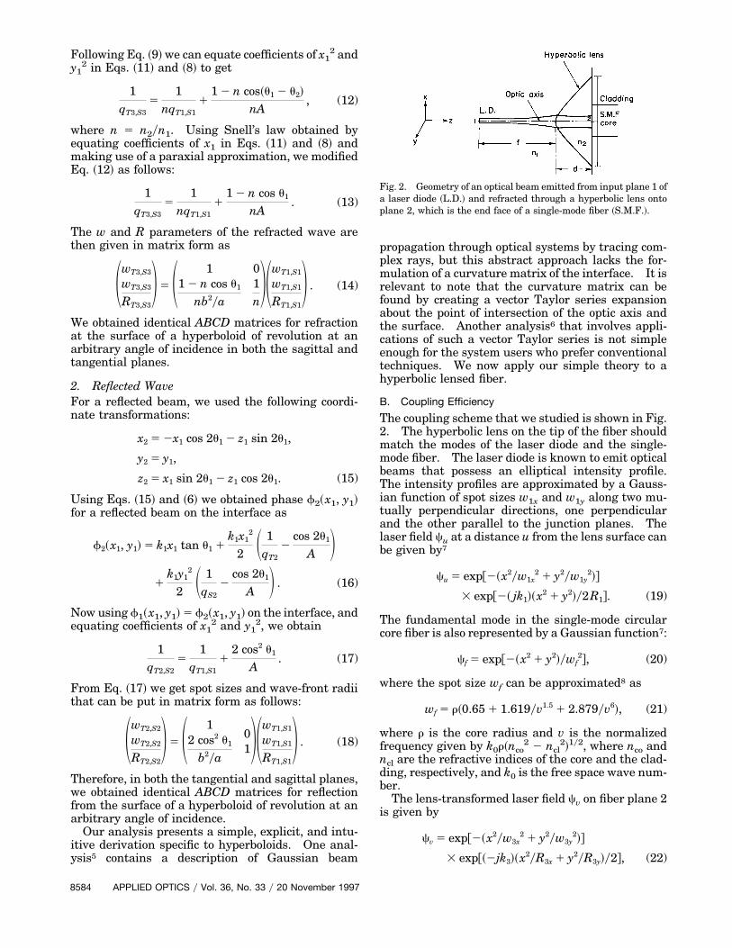
d 5 6 mm, and a single-mode fiber core diameter of 7.3mm. In Fig. 3 the solid curve represents the varia-tion of maximum coupling efficiency calculated withthe ABCD matrix versus the effective focal length ofthe lens. We used the input beam from the laserfacet as a spherical wave front, and compared it withtwo theoretical curves3: dotted curve, the planarwave model for the incident wave front; the dashedcurve, the spherical wave model for the incident wavefront. Our model gives 96.14% efficiency for thesame optimum focal length value.3 The cross in Fig.3 represents the only published experimentalpoint1,10 with a coupling efficiency of 90%. Note thatthe highest known coupling efficiency of any match-ing device reported to date corresponds to an exper-imentally determined value of 90% efficiency without
Fig. 3. Variation of maximum coupling efficiency with the effec-tive focal length of a hyperbolic lens on the tip of a fiber. Com-parison of our theoretical results with the results in Refs. 1, 3, and10: 3, published experimental point1,10; solid curve, our theorybased on an ABCD matrix; dotted curve, theory3 derived with theplanar wave model; dashed curve, theory3 derived with the spher-ical wave model.
h 54w3xw3y~wf!
2
@~wf2 1 w3x
2!2 1 ~k32wf
4w3x4!y~4R3x
2!#0.5@~wf2 1 w3y
2!2 1 ~k32wf
4w3y4!y~4R3y
2!#0.5 . (26)
3. Results and Discussion
We present an ABCD matrix for reflection and refrac-tion of a Gaussian beam from a hyperboloid of revo-lution at an arbitrary angle of incidence. Then weapply this matrix under paraxial approximation tocalculate the coupling efficiency for laser diode tosingle-mode fiber excitation with a hyperbolic lens onthe tip of the fiber. This method simplifies the cal-culations to the extent that only a pocket calculator isnecessary. For comparison of our analysis, we referto an earlier study3 in which the theoretical modeltakes care of the phase shift on the lens surface. Weused similar parameters,3 namely, l 5 1.3 mm, w1x 51.081 mm, w1y 5 1.161 mm, wf 5 4.794 mm, n 5 1.55,
coating. Figure 3 also shows that for the sphericalwave model for an incident wave front, the maximumtheoretical efficiency calculated by the ABCD matrix,and also the maximum theoretical efficiency calculatedby the phase shift technique3 together with the maxi-mum experimental efficiency occur at a particular fo-cal length value. Taking into account the obviouslack of agreement between the two theoretical curves,3our curve based on a simple ABCD formalism evenunder paraxial approximation predicts coupling effi-ciency sufficiently accurately in the neighborhood ofoptimum focal length. Since our region of interestcenters around the optimum focal length of 12.3 mm,we can justify the accuracy of our model and recom-mend its application for related coupling optics.
20 November 1997 y Vol. 36, No. 33 y APPLIED OPTICS 8585
4. Conclusion
The ABCD matrix for reflection and refraction of aGaussian laser beam at an arbitrary angle of inci-dence from a hyperboloidal interface between differ-ent dielectric media has been formulated by matchingthe optical phase at the interface. Using these ma-trices, a variety of practical problems that involvesuch surfaces can be readily solved. To illustratethe applicability of the matrix, we use the refractionmatrix under paraxial approximation for the calcu-lation of coupling efficiency of a source to single-modefiber excitation with a hyperbolic lens formed on itstip. The excellent agreement of our results with theavailable theoretical and experimental results veri-fies the validity of the formulated matrix and justifiesour simple technique that can be used even with apocket calculator. The technique should be usefulfor designing microlenses on fiber tips for maximumcoupling efficiency.
The financial support of the Council of Scientificand Industrial Research, India, is gratefully acknowl-edged. The authors are grateful to an anonymousreviewer for constructive suggestions and also toP. K. Basu of the Department of Radio Physics andElectronics, Calcutta University, for his help in pro-curing two references suggested by the reviewer.
8586 APPLIED OPTICS y Vol. 36, No. 33 y 20 November 1997
References1. H. M. Presby and C. A. Edwards, “Near 100% efficient fibre
microlenses,” Electron. Lett. 28, 582–584 ~1992!.2. C. A. Edwards, H. M. Presby, and C. Dragone, “Ideal micro-
lenses for laser to fiber coupling,” J. Lightwave Technol. 11,252–257 ~1993!.
3. J. John, T. S. M. Maclean, H. Ghafouri-Shiraz, and J. Niolett,“Matching of single-mode fibre to laser diode by microlenses at1.5 mm wavelength,” IEE Proc. Optoelectron. 141, 178–184~1994!.
4. G. A. Massey and A. E. Siegman, “Reflection and refraction ofGaussian light beams at tilted ellipsoidal surfaces,” Appl. Opt.8, 975–978 ~1969!.
5. G. A. Deschamps, “Ray techniques in electromagnetics,” Proc.IEEE 60, 1022–1035 ~1972!.
6. S. Solimeno, B. Crosignani, and P. Diporto, Guiding, Diffrac-tion and Confinement of Optical Radiation ~Academic, NewYork, 1986!, Chap. 2, pp. 81–89.
7. S. Sarkar, K. Thyagarajan, and A. Kumar, “Gaussian approx-imation of the fundamental mode in single-mode elliptical corefibers,” Opt. Commun. 49, 178–183 ~1984!.
8. D. Marcuse, “Loss analysis of single-mode fibre splices,” BellSyst. Tech. J. 56, 703–718 ~1977!.
9. S. N. Sarkar, B. P. Pal, and K. Thyagarajan, “Lens coupling oflaser diodes to monomode elliptic core fibers,” J. Opt. Commun.7, 92–96 ~1986!.
10. H. M. Presby and C. A. Edwards, “Efficient coupling of polari-sation maintaining fibre to laser diodes,” IEEE Photon. Tech-nol. Lett. 4, 897–899 ~1992!.