Embed Size (px)
Citation preview
abcd
5
Issue : 7 Date : March 04Fitting : ZA 180 Series of 203mm (8”) dia. High Intensity, Inset
Runway Lights.Author : ALL
Ref : L:\Avd\IMM CURRENT\document1 Page :1 of 28©2004 ALSTOM Ltd ALSTOM Power Conversion Ltd
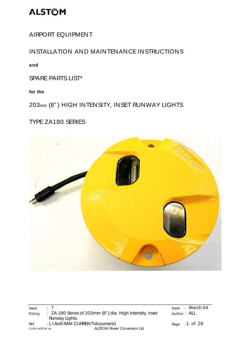
AIRPORT EQUIPMENT
INSTALLATION AND MAINTENANCE INSTRUCTIONS
and
SPARE PARTS LIST*
for the
203MM (8”) HIGH INTENSITY, INSET RUNWAY LIGHTS
TYPE ZA180 SERIES
abcd
5
Issue : 7 Date : March 04Fitting : ZA 180 Series of 203mm (8”) dia. High Intensity, Inset
Runway Lights.Author : ALL
Ref : L:\Avd\IMM CURRENT\document1 Page :2 of 28©2004 ALSTOM Ltd ALSTOM Power Conversion Ltd
CONTENTS
ISSUE RECORD, SAFETY ADVICE NOTICE, TOOLS & CONSUMABLES .......................3
ZA 180 SERIES HIGH INTENSITY, INSET RUNWAY LIGHT............................................4
1. INTRODUCTION.....................................................................................................4
2. PREPARE SITE FOR INSTALLATION OF ZM181 SEATING POT...............................4
3. INSTALLATION INTO ZM181 SEATING POT OR ADAPTOR..................................53.1 PERIODIC CHECK OF THE INSTALLATION................................................6
4 REMOVE A FITTING FROM A SEATING POT..........................................................6
5. MAINTENANCE ON SITE........................................................................................7
6. WORKSHOP MAINTENANCE .................................................................................86.1 POLICY........................................................................................................86.2 PREPARE TO DIS-ASSEMBLE........................................................................86.3 DIS-ASSEMBLE BODY ASSEMBLY & BOTTOM COVER ASSEMBLY.............86.4 MAINTAIN THE BODY ASSEMBLY ..............................................................96.5 MAINTAIN BOTTOM COVER ASSEMBLY..................................................126.6 RE-ASSEMBLE BOTTOM COVER AND BODY CASTING..........................18
7. SPARES FOR ZA181, ZA182 & ZA183 FITTINGS..................................................197.1 ZA181 CENTRELINE & TDZ FITTING ORDERING CODE .........................197.2 ZA182 RUNWAY END FITTING ORDERING CODE .................................207.3 ZA183 RUNWAY EDGE FITTING ORDERING CODE ...............................217.4 SPARE PARTS ORDERING..........................................................................22
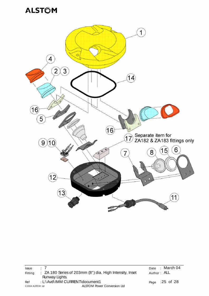
EXPLODED VIEW ..........................................................................................................25
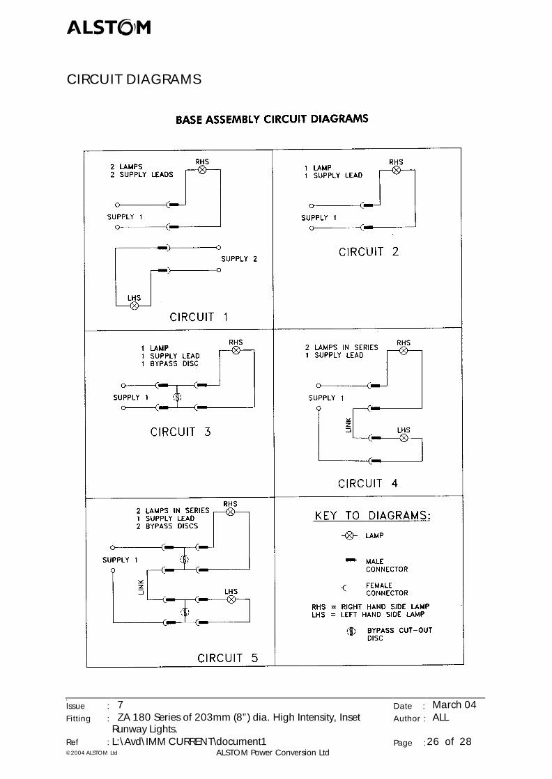
CIRCUIT DIAGRAM ......................................................................................................26
APPENDIX 'A' - SAFETY ADVICE ...................................................................................27
1. COMPLIANCE WITH INSTRUCTIONS IN THIS MANUAL .....................................27
2. GUIDANCE NOTES FOR USERS ON THE SAFETY OF PERSONNEL ....................27
3. INSTALLATION, OPERATION AND MAINTENANCE............................................27
4. VOLTAGES GREATER THAN 50V A.C./120V D.C................................................28
5. APPARATUS SUPPLIED AS LOOSE ITEMS, CHASSIS ETC......................................28
6. ACCESS TO THE APPARATUS DESCRIBED IN THIS MANUAL ..............................28
abcd
5
Issue : 7 Date : March 04Fitting : ZA 180 Series of 203mm (8”) dia. High Intensity, Inset
Runway Lights.Author : ALL
Ref : L:\Avd\IMM CURRENT\document1 Page :3 of 28©2004 ALSTOM Ltd ALSTOM Power Conversion Ltd
ISSUE RECORD
Issue Status
ISSUE: 5 6 7
DATE: Sept. 2003 Oct. 2003 March 2004
AUTHOR: A L Landless A L Landless A L Landless
AUTHORISED: P M Humber P M Humber P M Humber
SAFETY ADVICE NOTICE
Please ensure that personnel are made aware of all safety aspects. Appendix ‘B’ containssafety advice. This appendix can be copied and used to record authorised personnel.
TOOLS AND CONSUMABLES
• 11mm A/F Hex. socket
• Torque wrench.
• 5mm A/F Hex. Allen key.
• Ambersil 10008A black sealant.
• 17mm A/F Hex. socket.
• Loctite 648.
• Low voltage Multi-meter.
• 1/8th BSP adaptor, for air pressure test.
• Compressed Air line capable 30 PSI. or Alstom portable Air Pressure Test Equipment.
abcd
5
Issue : 7 Date : March 04Fitting : ZA 180 Series of 203mm (8”) dia. High Intensity, Inset
Runway Lights.Author : ALL
Ref : L:\Avd\IMM CURRENT\document1 Page :4 of 28©2004 ALSTOM Ltd ALSTOM Power Conversion Ltd
ZA180 SERIES, 203MM (8”) DIAMETER HIGH INTENSITY, INSETRUNWAY LIGHTS
1. INTRODUCTION
The ZA180 series, high intensity, inset runway fittings are designed to meet ICAOrequirements for Categories I, II and III, all weather operation lighting systems. Thefittings are designated as follows:
ZA181 Runway Centreline and Touch Down Zone (TDZ).ZA182 Runway End.ZA183 Runway Edge.
Fittings are supplied with 1 or 2 long life, low energy reflector lamp(s) and 1 or 2, 'B'type (L823) plug lead(s). 2 leads are used on switchable, bi-directional fittings.
When required, an internal lamp by-pass device is available as an option.
The fittings are lightweight and robust due to their predominantly aluminium alloyconstruction that also provides excellent protection against corrosion. The glassprisms or blanks are accurately located in the main body casting, secured by analuminium alloy retaining clamp without the need for sealing compounds.
The optical system employed is completely free of adjustment, either at the installationor in service, thus simplifying installation and maintenance procedures.
The fitting is suitable for installation into a 203mm (8”) diameter ZM181 seating pot,either ‘dry’ or ‘wet’ version.
A range of PSA and FAA style adaptors are also available to fit 305mm (12") and394mm (15.5") diameter mountings.
Seating pots and adaptors are supplied separately to order.
2. PREPARE SITE FOR INSTALLATION OF ZM181 SEATING POT
Prior to the installation of the seating pot, the runway pavement surface must becorrectly prepared.
• Pre-form or trepan a hole, 250mm in diameter and minimum depth of 160mm, atthe correct location in the runway in accordance with the site plan.
When bottom cable entry is required, a ‘wet’ Seating Pot is supplied with an entry holein the base.
• Excavate a further hole, not greater than 130mm in diameter, beneath the seatingpot.
Note. When a side cable entry is to be employed no additional storage space needs tobe provided beneath the seating pot to accommodate cables and connectors.
abcd
5
Issue : 7 Date : March 04Fitting : ZA 180 Series of 203mm (8”) dia. High Intensity, Inset
Runway Lights.Author : ALL
Ref : L:\Avd\IMM CURRENT\document1 Page :5 of 28©2004 ALSTOM Ltd ALSTOM Power Conversion Ltd
• Install the seating pot in accordance with Alstom Installation and MaintenanceInstructions ‘imm-zm-seating-pots-3’.
3. INSTALLATION INTO ZM181 SEATING POT OR ADAPTOR
At this stage the seating pot and transformer secondary socket lead(s) are installed.
See Appendix ‘A’ for power supply convention used with twin lead fittings.
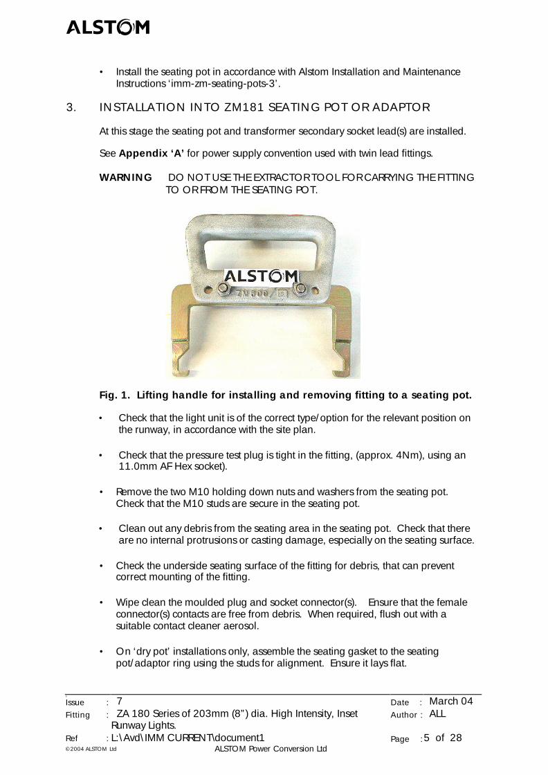
WARNING DO NOT USE THE EXTRACTOR TOOL FOR CARRYING THE FITTINGTO OR FROM THE SEATING POT.
Fig. 1. Lifting handle for installing and removing fitting to a seating pot.
• Check that the light unit is of the correct type/option for the relevant position onthe runway, in accordance with the site plan.
• Check that the pressure test plug is tight in the fitting, (approx. 4Nm), using an11.0mm AF Hex socket).
• Remove the two M10 holding down nuts and washers from the seating pot.Check that the M10 studs are secure in the seating pot.
• Clean out any debris from the seating area in the seating pot. Check that thereare no internal protrusions or casting damage, especially on the seating surface.
• Check the underside seating surface of the fitting for debris, that can preventcorrect mounting of the fitting.
• Wipe clean the moulded plug and socket connector(s). Ensure that the femaleconnector(s) contacts are free from debris. When required, flush out with asuitable contact cleaner aerosol.
• On ‘dry pot’ installations only, assemble the seating gasket to the seatingpot/adaptor ring using the studs for alignment. Ensure it lays flat.
abcd
5
Issue : 7 Date : March 04Fitting : ZA 180 Series of 203mm (8”) dia. High Intensity, Inset
Runway Lights.Author : ALL
Ref : L:\Avd\IMM CURRENT\document1 Page :6 of 28©2004 ALSTOM Ltd ALSTOM Power Conversion Ltd
• Connect the plug from secondary lead(s) into the appropriate transformer socketon the secondary lead(s), in accordance with the site layout plan. Take care toobserve the correct pin polarisation.
• Install the light unit into the seating pot, oriented correctly to the site plan, using theextractor tool recommended for this purpose, (ALSTOM type SLC21226). Take carenot to trap any leads between mating surfaces.
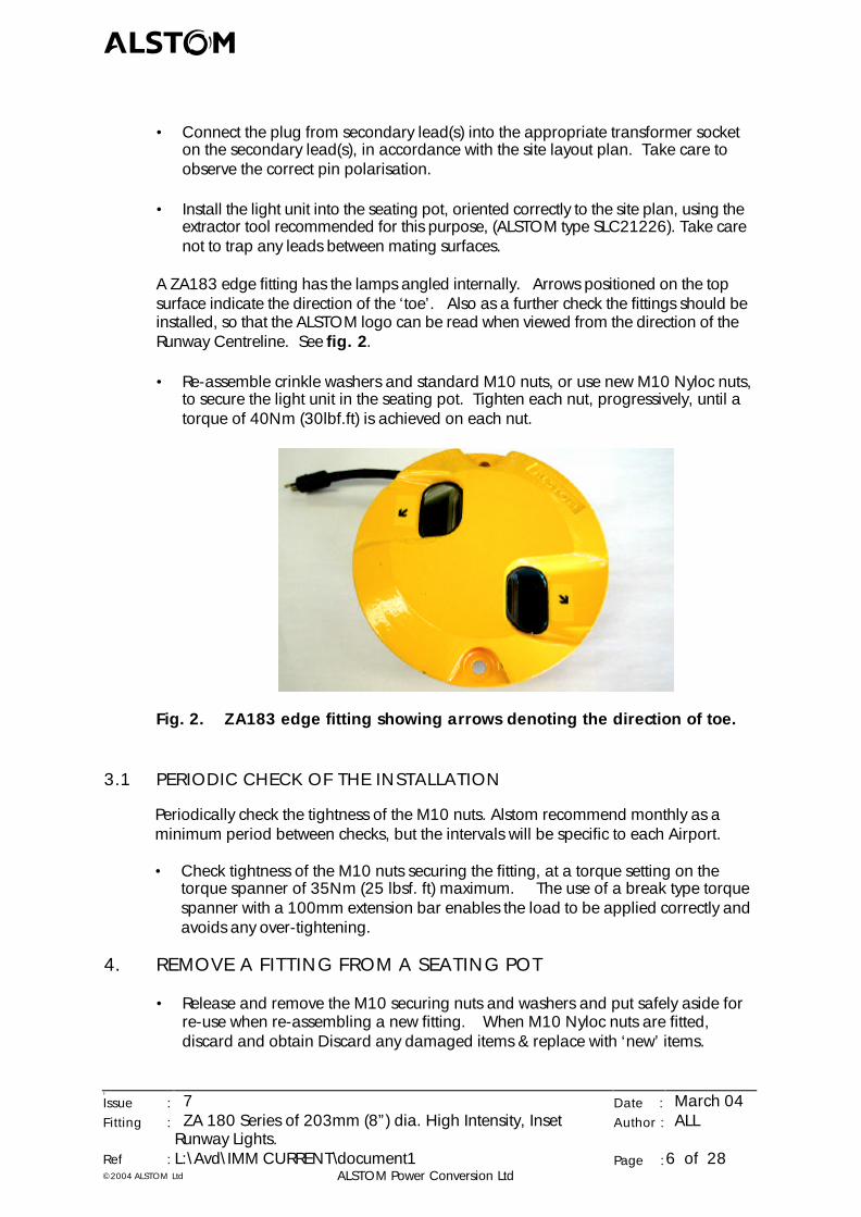
A ZA183 edge fitting has the lamps angled internally. Arrows positioned on the topsurface indicate the direction of the ‘toe’. Also as a further check the fittings should beinstalled, so that the ALSTOM logo can be read when viewed from the direction of theRunway Centreline. See fig. 2.
• Re-assemble crinkle washers and standard M10 nuts, or use new M10 Nyloc nuts,to secure the light unit in the seating pot. Tighten each nut, progressively, until atorque of 40Nm (30lbf.ft) is achieved on each nut.
Fig. 2. ZA183 edge fitting showing arrows denoting the direction of toe.
3.1 PERIODIC CHECK OF THE INSTALLATION
Periodically check the tightness of the M10 nuts. Alstom recommend monthly as aminimum period between checks, but the intervals will be specific to each Airport.
• Check tightness of the M10 nuts securing the fitting, at a torque setting on thetorque spanner of 35Nm (25 lbsf. ft) maximum. The use of a break type torquespanner with a 100mm extension bar enables the load to be applied correctly andavoids any over-tightening.
4. REMOVE A FITTING FROM A SEATING POT
• Release and remove the M10 securing nuts and washers and put safely aside forre-use when re-assembling a new fitting. When M10 Nyloc nuts are fitted,discard and obtain Discard any damaged items & replace with ‘new’ items.
abcd
5
Issue : 7 Date : March 04Fitting : ZA 180 Series of 203mm (8”) dia. High Intensity, Inset
Runway Lights.Author : ALL
Ref : L:\Avd\IMM CURRENT\document1 Page :7 of 28©2004 ALSTOM Ltd ALSTOM Power Conversion Ltd
• Remove the fitting from the seating pot using the extractor tool recommended forthis purpose, (ALSTOM type SLC21226).
WARNING DO NOT USE THE EXTRACTOR TOOL FOR CARRYING THE FITTINGTO OR FROM THE SEATING POT.
5. MAINTENANCE ON SITE
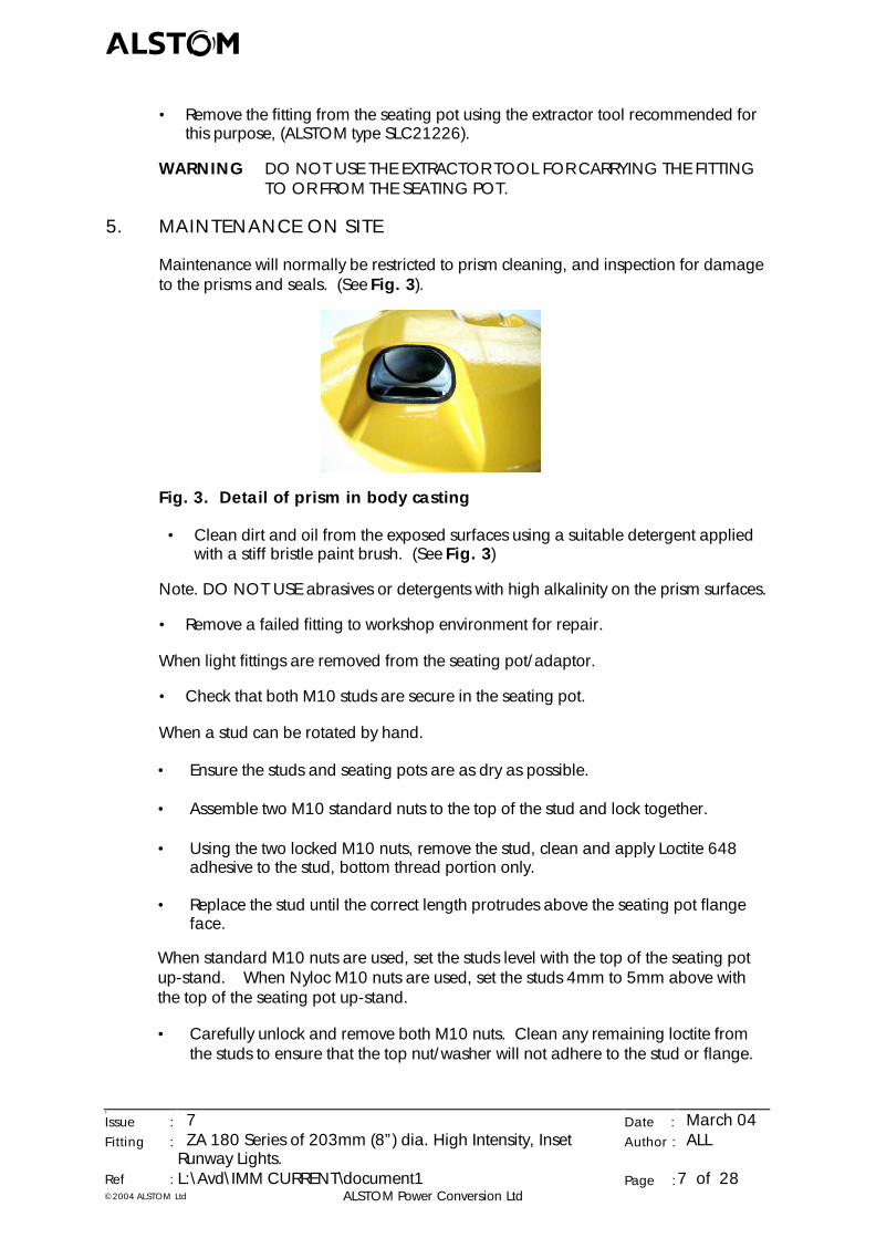
Maintenance will normally be restricted to prism cleaning, and inspection for damageto the prisms and seals. (See Fig. 3).
Fig. 3. Detail of prism in body casting
• Clean dirt and oil from the exposed surfaces using a suitable detergent appliedwith a stiff bristle paint brush. (See Fig. 3)
Note. DO NOT USE abrasives or detergents with high alkalinity on the prism surfaces.
• Remove a failed fitting to workshop environment for repair.
When light fittings are removed from the seating pot/adaptor.
• Check that both M10 studs are secure in the seating pot.
When a stud can be rotated by hand.
• Ensure the studs and seating pots are as dry as possible.
• Assemble two M10 standard nuts to the top of the stud and lock together.
• Using the two locked M10 nuts, remove the stud, clean and apply Loctite 648adhesive to the stud, bottom thread portion only.
• Replace the stud until the correct length protrudes above the seating pot flangeface.
When standard M10 nuts are used, set the studs level with the top of the seating potup-stand. When Nyloc M10 nuts are used, set the studs 4mm to 5mm above withthe top of the seating pot up-stand.
• Carefully unlock and remove both M10 nuts. Clean any remaining loctite fromthe studs to ensure that the top nut/washer will not adhere to the stud or flange.
abcd
5
Issue : 7 Date : March 04Fitting : ZA 180 Series of 203mm (8”) dia. High Intensity, Inset
Runway Lights.Author : ALL
Ref : L:\Avd\IMM CURRENT\document1 Page :8 of 28©2004 ALSTOM Ltd ALSTOM Power Conversion Ltd
• When fitted in a ‘dry pot’ application, re-assemble the gasket to the seating pot.
• Re-assemble the fitting to the seating pot, re-assemble M10 nuts and crinklewashers. Only hand tighten the M10 nuts at this stage.
• Allow at least 30 minutes for the Loctite 648 adhesive to cure.
• Torque tighten the fitting into seating pot, to 40Nm (30lbsf.ft) maximum.
6. WORKSHOP MAINTENANCE
6.1 POLICY
To minimise future failures in service, initially.
• Establish an efficient spares holding policy.
• Generate a record of the status of fittings and major components kept.
6.2 PREPARE TO DIS-ASSEMBLE
When a light fitting is to be dis-assembled, either for lamp changing or at plannedmaintenance intervals, clean any dirt or oil from the exterior of the fitting, to avoidinternal contamination when the fitting is dis-assembled.
• Clean the fitting externally using a suitable household detergent applied with astiff bristle paint brush. Finally wash in clean water and dry with a lint free cloth.
DO NOT USE compressed air directly onto the prism faces. DO NOT clean theprisms with any abrasive substances or detergents with high alkalinity.
• Transport the fitting to a workshop environment, that is clean, free from dustand/or atmospheric pollutants likely to cause contamination of prism, lamp andreflector surfaces.
6.3 DIS-ASSEMBLE BODY ASSEMBLY FROM BOTTOM COVER ASSEMBLY
The main tool required for stripping the fitting down to its component parts is a 5mmA/F Allen key. During dis-assembly, discard any damaged items and replace with‘new’ items. Store all items safely for re-assembly.
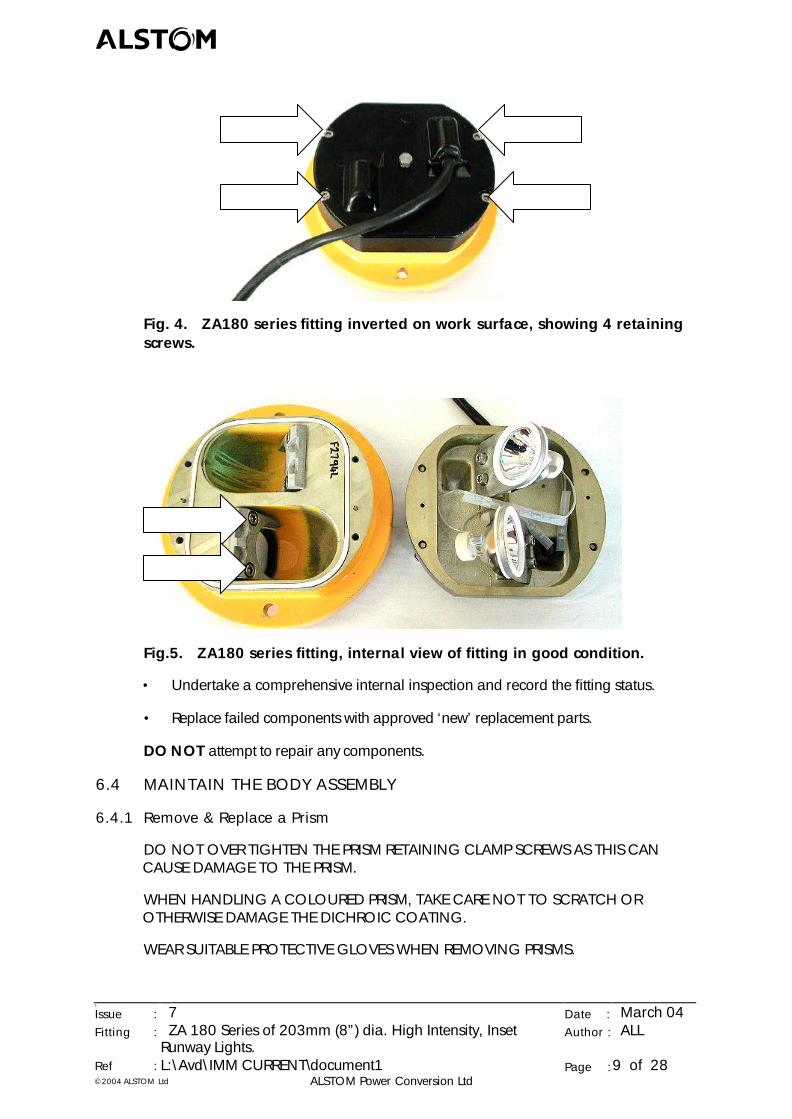
• Place the light fitting on a clean, flat, work surface with its bottom coveruppermost. (See Fig. 4.)
• Release the two M6 cap head screws attaching the base casting to the bodycasting. (See Fig. 4).
• Carefully lift off the bottom cover assembly and place ‘bottom down’ on the worksurface. (See Fig. 5).
abcd
5
Issue : 7 Date : March 04Fitting : ZA 180 Series of 203mm (8”) dia. High Intensity, Inset
Runway Lights.Author : ALL
Ref : L:\Avd\IMM CURRENT\document1 Page :9 of 28©2004 ALSTOM Ltd ALSTOM Power Conversion Ltd
Fig. 4. ZA180 series fitting inverted on work surface, showing 4 retainingscrews.
Fig.5. ZA180 series fitting, internal view of fitting in good condition.
• Undertake a comprehensive internal inspection and record the fitting status.
• Replace failed components with approved ‘new’ replacement parts.
DO NOT attempt to repair any components.
6.4 MAINTAIN THE BODY ASSEMBLY
6.4.1 Remove & Replace a Prism
DO NOT OVER TIGHTEN THE PRISM RETAINING CLAMP SCREWS AS THIS CANCAUSE DAMAGE TO THE PRISM.
WHEN HANDLING A COLOURED PRISM, TAKE CARE NOT TO SCRATCH OROTHERWISE DAMAGE THE DICHROIC COATING.
WEAR SUITABLE PROTECTIVE GLOVES WHEN REMOVING PRISMS.
abcd
5
Issue : 7 Date : March 04Fitting : ZA 180 Series of 203mm (8”) dia. High Intensity, Inset
Runway Lights.Author : ALL
Ref : L:\Avd\IMM CURRENT\document1 Page :10 of 28©2004 ALSTOM Ltd ALSTOM Power Conversion Ltd
• Release the two M6 socket head screws and dis-assemble the prism clamp & prismclamp gasket. (See Fig. 5).
• Check prism front and rear optical surfaces, for contamination and physicaldamage.
• Check sealing around prisms for obvious evidence of water ingress.
When removing a prism/prism gasket assembly that is intact. (i.e. the prism is notbroken).
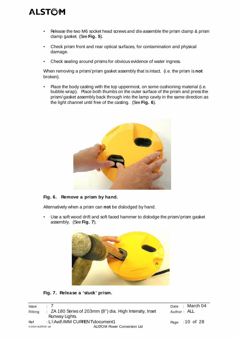
• Place the body casting with the top uppermost, on some cushioning material (i.e.bubble wrap). Place both thumbs on the outer surface of the prism and press theprism/gasket assembly back through into the lamp cavity in the same direction asthe light channel until free of the casting. (See Fig. 6).
Fig. 6. Remove a prism by hand.
Alternatively when a prism can not be dislodged by hand.
• Use a soft wood drift and soft faced hammer to dislodge the prism/prism gasketassembly. (See Fig. 7).
Fig. 7. Release a ‘stuck’ prism.
abcd
5
Issue : 7 Date : March 04Fitting : ZA 180 Series of 203mm (8”) dia. High Intensity, Inset
Runway Lights.Author : ALL
Ref : L:\Avd\IMM CURRENT\document1 Page :11 of 28©2004 ALSTOM Ltd ALSTOM Power Conversion Ltd
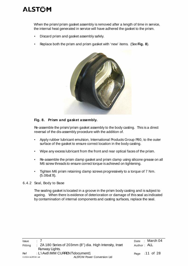
When the prism/prism gasket assembly is removed after a length of time in service,the internal heat generated in service will have adhered the gasket to the prism.
• Discard prism and gasket assembly safely.
• Replace both the prism and prism gasket with ‘new’ items. (See Fig. 8).
Fig. 8. Prism and gasket assembly.
Re-assemble the prism/prism gasket assembly to the body casting. This is a directreversal of the dis-assembly procedure with the addition of.
• Apply rubber lubricant emulsion, International Products Group P80, to the outersurface of the gasket to ensure correct location in the body casting.
• Wipe any excess lubricant from the front and rear optical faces of the prism.
• Re-assemble the prism clamp gasket and prism clamp using silicone grease on allM6 screw threads to ensure correct torque is achieved on tightening.
• Tighten M6 prism retaining clamp screws progressively to a torque of 7 Nm.(5.0lbsf.ft).
6.4.2 Seal, Body to Base
The sealing gasket is located in a groove in the prism body casting and is subject toageing. When there is evidence of deterioration or damage of this seal as indicatedby contamination of internal components and casting surfaces, replace the seal.
abcd
5
Issue : 7 Date : March 04Fitting : ZA 180 Series of 203mm (8”) dia. High Intensity, Inset
Runway Lights.Author : ALL
Ref : L:\Avd\IMM CURRENT\document1 Page :12 of 28©2004 ALSTOM Ltd ALSTOM Power Conversion Ltd
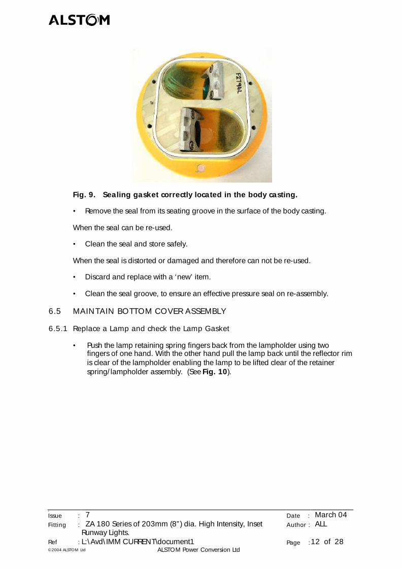
Fig. 9. Sealing gasket correctly located in the body casting.
• Remove the seal from its seating groove in the surface of the body casting.
When the seal can be re-used.
• Clean the seal and store safely.
When the seal is distorted or damaged and therefore can not be re-used.
• Discard and replace with a ‘new’ item.
• Clean the seal groove, to ensure an effective pressure seal on re-assembly.
6.5 MAINTAIN BOTTOM COVER ASSEMBLY
6.5.1 Replace a Lamp and check the Lamp Gasket
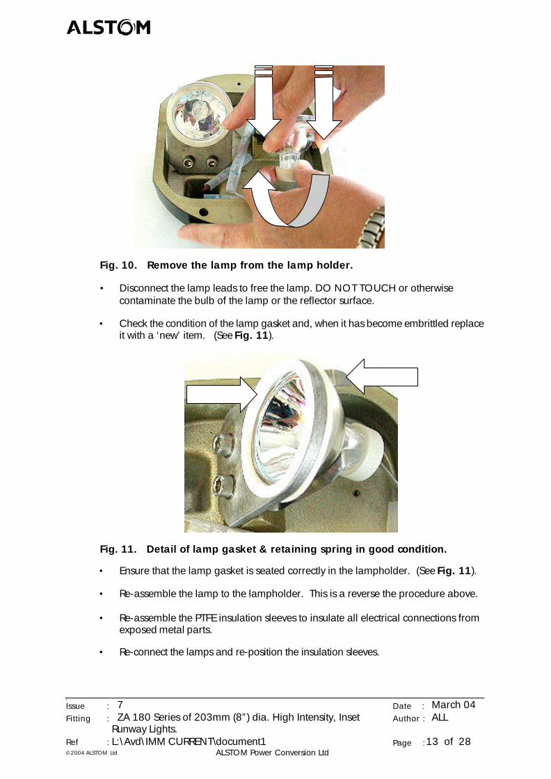
• Push the lamp retaining spring fingers back from the lampholder using twofingers of one hand. With the other hand pull the lamp back until the reflector rimis clear of the lampholder enabling the lamp to be lifted clear of the retainerspring/lampholder assembly. (See Fig. 10).
abcd
5
Issue : 7 Date : March 04Fitting : ZA 180 Series of 203mm (8”) dia. High Intensity, Inset
Runway Lights.Author : ALL
Ref : L:\Avd\IMM CURRENT\document1 Page :13 of 28©2004 ALSTOM Ltd ALSTOM Power Conversion Ltd
Fig. 10. Remove the lamp from the lamp holder.
• Disconnect the lamp leads to free the lamp. DO NOT TOUCH or otherwisecontaminate the bulb of the lamp or the reflector surface.
• Check the condition of the lamp gasket and, when it has become embrittled replaceit with a ‘new’ item. (See Fig. 11).
Fig. 11. Detail of lamp gasket & retaining spring in good condition.
• Ensure that the lamp gasket is seated correctly in the lampholder. (See Fig. 11).
• Re-assemble the lamp to the lampholder. This is a reverse the procedure above.
• Re-assemble the PTFE insulation sleeves to insulate all electrical connections fromexposed metal parts.
• Re-connect the lamps and re-position the insulation sleeves.
abcd
5
Issue : 7 Date : March 04Fitting : ZA 180 Series of 203mm (8”) dia. High Intensity, Inset
Runway Lights.Author : ALL
Ref : L:\Avd\IMM CURRENT\document1 Page :14 of 28©2004 ALSTOM Ltd ALSTOM Power Conversion Ltd
6.5.2 Lampholder/Lamp Retaining Spring
• Check the lampholder condition and the lamp retaining spring for lack of springpressure. (See Fig. 11).
When lack of spring pressure, or damage is evident.
• Release two M6 cap head screws and remove the lampholder and retainingspring.
• Re-assemble ‘new’ item(s) and secure with M6 screws torque tightened to 7Nm(5.0lbs,ft.).
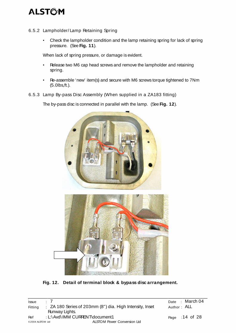
6.5.3 Lamp By-pass Disc Assembly (When supplied in a ZA183 fitting)
The by-pass disc is connected in parallel with the lamp. (See Fig. 12).
Fig. 12. Detail of terminal block & bypass disc arrangement.
abcd
5
Issue : 7 Date : March 04Fitting : ZA 180 Series of 203mm (8”) dia. High Intensity, Inset
Runway Lights.Author : ALL
Ref : L:\Avd\IMM CURRENT\document1 Page :15 of 28©2004 ALSTOM Ltd ALSTOM Power Conversion Ltd
• Check the female receptacles and male tabs on the connector block for signs ofcontamination or arcing, (due to water ingress or loose connections).
• Dis-assemble the bypass disc from under the retaining spring on the terminalblock and check for any surface contamination, (which could prevent the electricalbypass activating during a future lamp failure).
• Wipe the bypass disc with a clean lint free cloth to remove any contamination.
When contamination cannot be wiped off.
• Discard the bypass disc and replace with a ‘new’ bypass disc.
• Inspect the disc mating surfaces of the terminal block and, when required, cleancontact surfaces using a fine grade of emery paper (or similar).
• Check that the disc is not in a short circuit condition, using a low voltage multi-meter. When it is shorted out discard and replace it with a ‘new’ item of the samevalue. (100W).
• Assemble a ‘new’ disc to the terminal block.
When fittings have a lamp by-pass facility supplied, which is not being used.
• Assemble an insulation disc under the retaining spring on the terminal block.
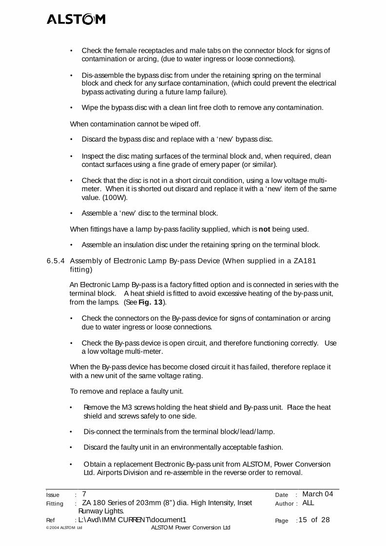
6.5.4 Assembly of Electronic Lamp By-pass Device (When supplied in a ZA181fitting)
An Electronic Lamp By-pass is a factory fitted option and is connected in series with theterminal block. A heat shield is fitted to avoid excessive heating of the by-pass unit,from the lamps. (See Fig. 13).
• Check the connectors on the By-pass device for signs of contamination or arcingdue to water ingress or loose connections.
• Check the By-pass device is open circuit, and therefore functioning correctly. Usea low voltage multi-meter.
When the By-pass device has become closed circuit it has failed, therefore replace itwith a new unit of the same voltage rating.
To remove and replace a faulty unit.
• Remove the M3 screws holding the heat shield and By-pass unit. Place the heatshield and screws safely to one side.
• Dis-connect the terminals from the terminal block/lead/lamp.
• Discard the faulty unit in an environmentally acceptable fashion.
• Obtain a replacement Electronic By-pass unit from ALSTOM, Power ConversionLtd. Airports Division and re-assemble in the reverse order to removal.
abcd
5
Issue : 7 Date : March 04Fitting : ZA 180 Series of 203mm (8”) dia. High Intensity, Inset
Runway Lights.Author : ALL
Ref : L:\Avd\IMM CURRENT\document1 Page :16 of 28©2004 ALSTOM Ltd ALSTOM Power Conversion Ltd
• Re-assemble the heat shields and secure with M3 screws, to ensure that the LampBy-pass does not become overheated thus shortening its operating life.
Fig. 13. Detail of Electronic Bypass arrangement. (Arrow shows heatshield covering the electronic by-pass device).
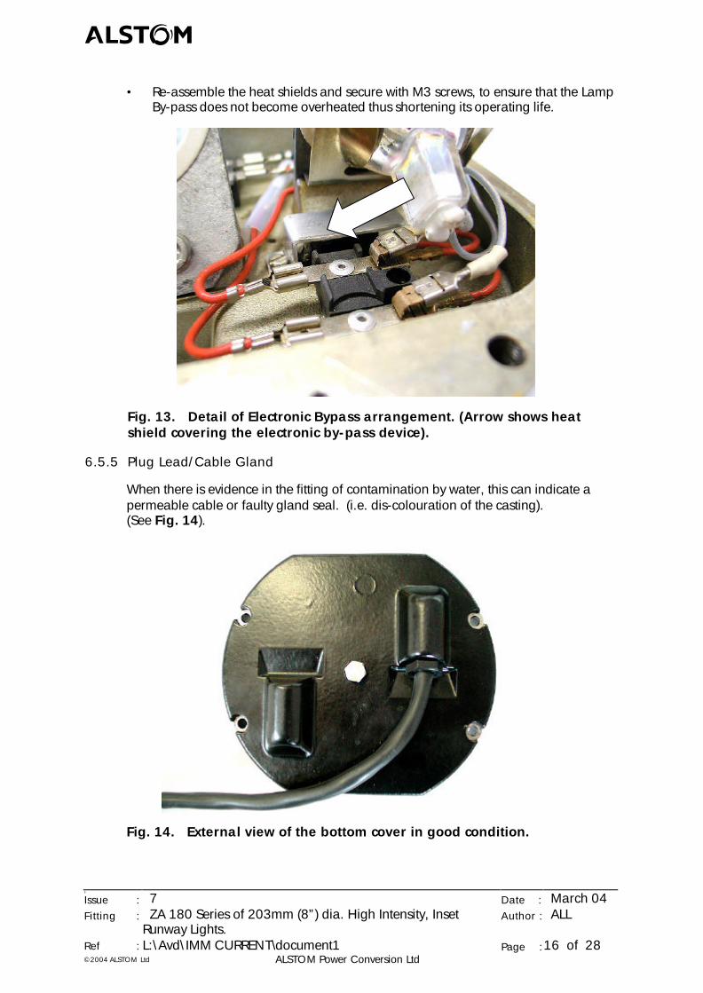
6.5.5 Plug Lead/Cable Gland
When there is evidence in the fitting of contamination by water, this can indicate apermeable cable or faulty gland seal. (i.e. dis-colouration of the casting).(See Fig. 14).
Fig. 14. External view of the bottom cover in good condition.
abcd
5
Issue : 7 Date : March 04Fitting : ZA 180 Series of 203mm (8”) dia. High Intensity, Inset
Runway Lights.Author : ALL
Ref : L:\Avd\IMM CURRENT\document1 Page :17 of 28©2004 ALSTOM Ltd ALSTOM Power Conversion Ltd
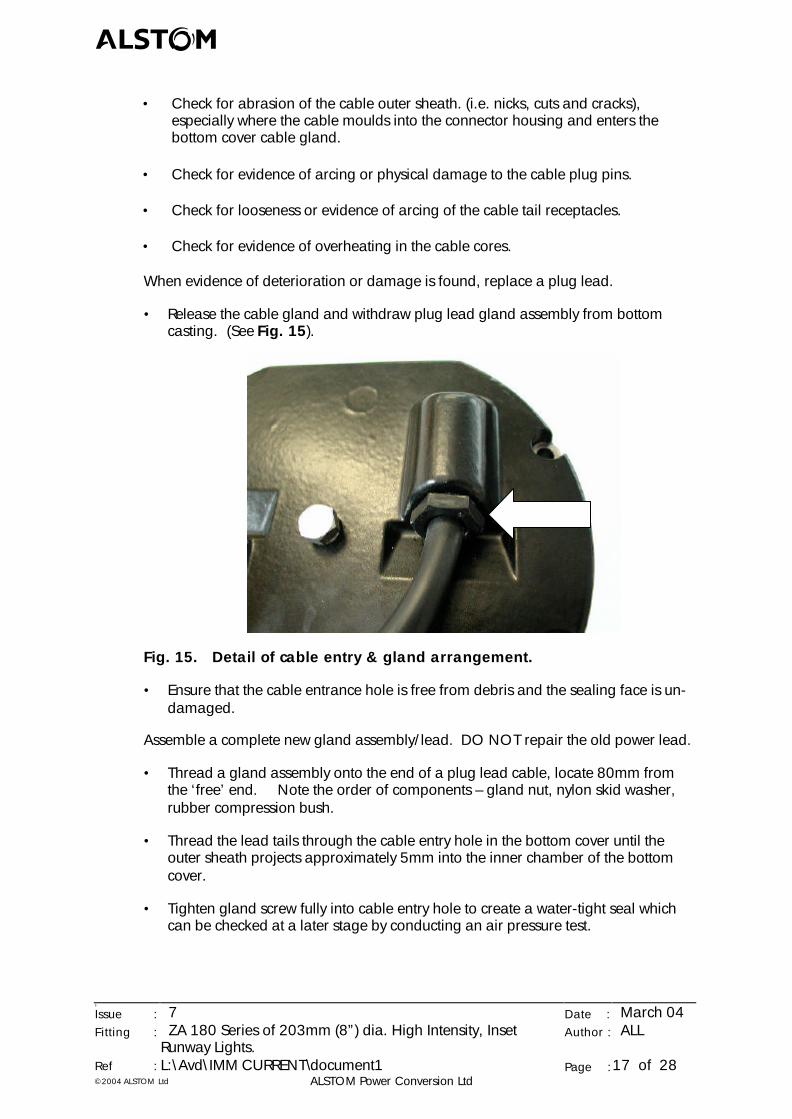
• Check for abrasion of the cable outer sheath. (i.e. nicks, cuts and cracks),especially where the cable moulds into the connector housing and enters thebottom cover cable gland.
• Check for evidence of arcing or physical damage to the cable plug pins.
• Check for looseness or evidence of arcing of the cable tail receptacles.
• Check for evidence of overheating in the cable cores.
When evidence of deterioration or damage is found, replace a plug lead.
• Release the cable gland and withdraw plug lead gland assembly from bottomcasting. (See Fig. 15).
Fig. 15. Detail of cable entry & gland arrangement.
• Ensure that the cable entrance hole is free from debris and the sealing face is un-damaged.
Assemble a complete new gland assembly/lead. DO NOT repair the old power lead.
• Thread a gland assembly onto the end of a plug lead cable, locate 80mm fromthe ‘free’ end. Note the order of components – gland nut, nylon skid washer,rubber compression bush.
• Thread the lead tails through the cable entry hole in the bottom cover until theouter sheath projects approximately 5mm into the inner chamber of the bottomcover.
• Tighten gland screw fully into cable entry hole to create a water-tight seal whichcan be checked at a later stage by conducting an air pressure test.
abcd
5
Issue : 7 Date : March 04Fitting : ZA 180 Series of 203mm (8”) dia. High Intensity, Inset
Runway Lights.Author : ALL
Ref : L:\Avd\IMM CURRENT\document1 Page :18 of 28©2004 ALSTOM Ltd ALSTOM Power Conversion Ltd
6.6 RE-ASSEMBLE BOTTOM COVER AND BODY CASTING
All faulty components are replaced and re-connected correctly as described inprevious sections.
• Place the prism body casting flat on a clean work surface, top surface downwards.Note. One of the two locating spiral pins is offset from the centreline of the fitting.
• Re-assemble the body to base seal in the body casting groove.
• Re-assemble the bottom cover assembly such that the offset location hole in thebottom cover mates with the corresponding offset spiral pin in the body casting.
• Re-assemble 4 off M6 cap head screws and crinkle washers, progressively tightento a torque of 9Nm (7.0 lbf.ft), on each screw.
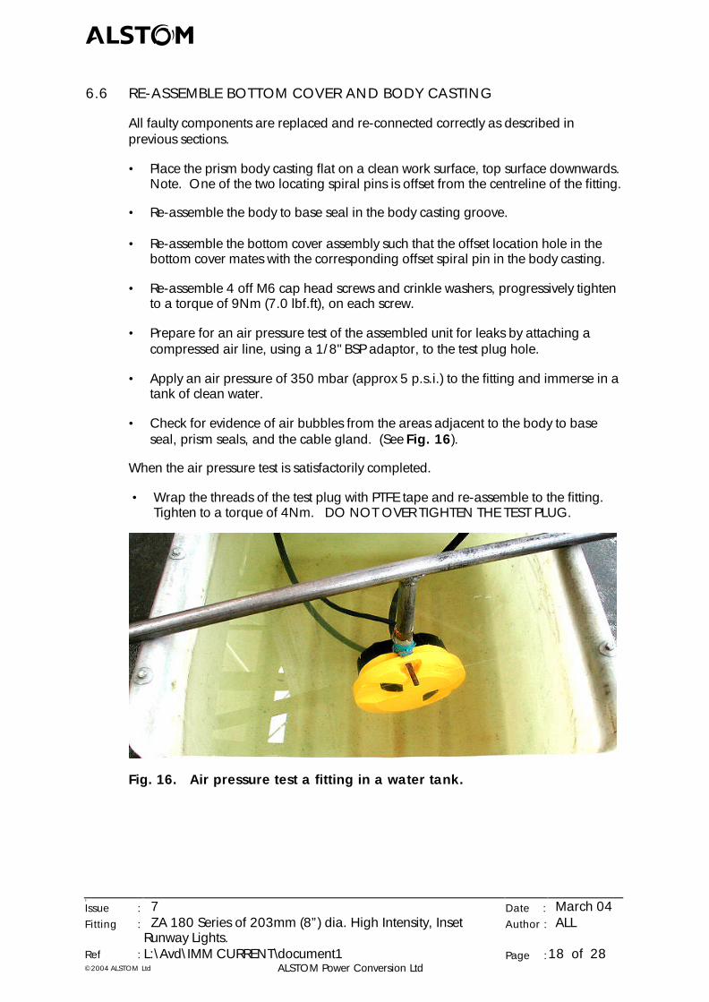
• Prepare for an air pressure test of the assembled unit for leaks by attaching acompressed air line, using a 1/8" BSP adaptor, to the test plug hole.
• Apply an air pressure of 350 mbar (approx 5 p.s.i.) to the fitting and immerse in atank of clean water.
• Check for evidence of air bubbles from the areas adjacent to the body to baseseal, prism seals, and the cable gland. (See Fig. 16).
When the air pressure test is satisfactorily completed.
• Wrap the threads of the test plug with PTFE tape and re-assemble to the fitting.Tighten to a torque of 4Nm. DO NOT OVER TIGHTEN THE TEST PLUG.
Fig. 16. Air pressure test a fitting in a water tank.
abcd
5
Issue : 7 Date : March 04Fitting : ZA 180 Series of 203mm (8”) dia. High Intensity, Inset
Runway Lights.Author : ALL
Ref : L:\Avd\IMM CURRENT\document1 Page :19 of 28©2004 ALSTOM Ltd ALSTOM Power Conversion Ltd
7. SPARES FOR ZA181, ZA182 & ZA183 FITTINGS
When ordering spare FITTINGS identify your requirement by using the followingordering code:
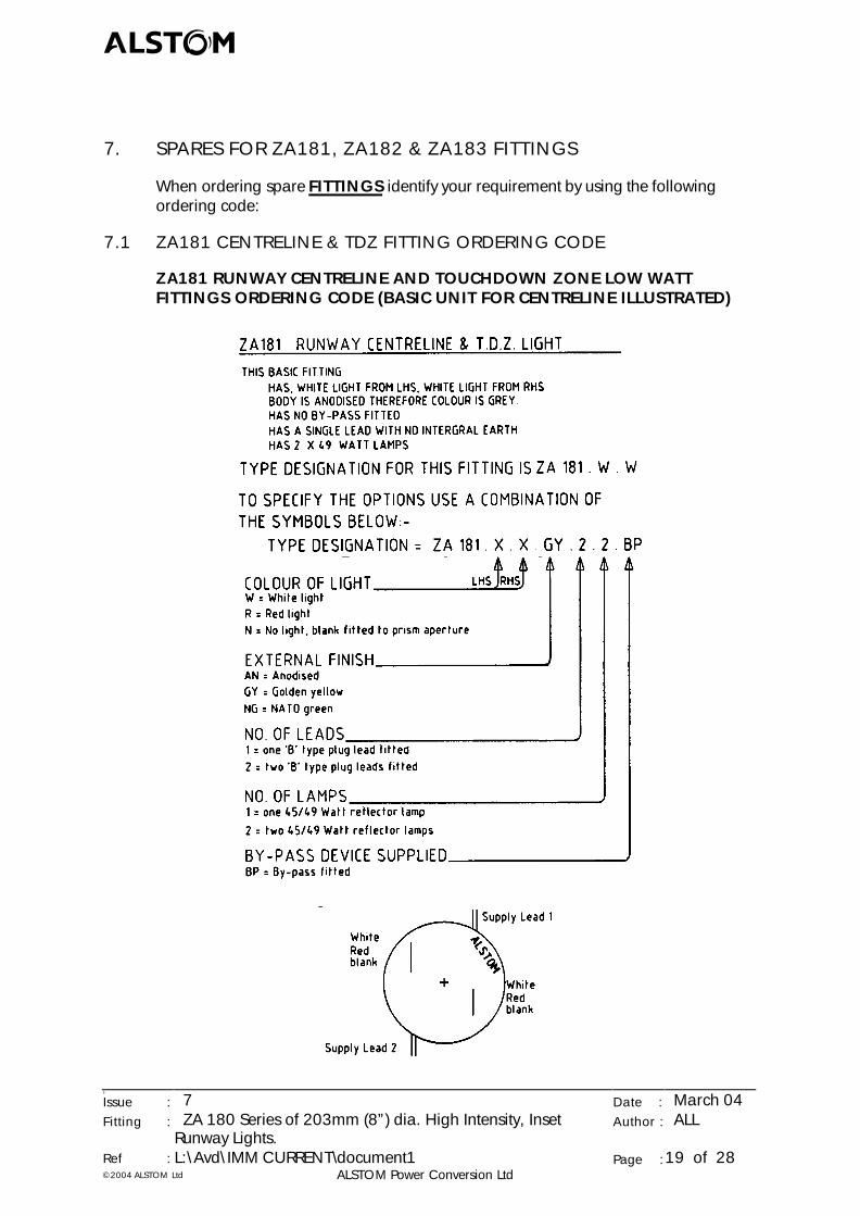
7.1 ZA181 CENTRELINE & TDZ FITTING ORDERING CODE
ZA181 RUNWAY CENTRELINE AND TOUCHDOWN ZONE LOW WATTFITTINGS ORDERING CODE (BASIC UNIT FOR CENTRELINE ILLUSTRATED)
abcd
5
Issue : 7 Date : March 04Fitting : ZA 180 Series of 203mm (8”) dia. High Intensity, Inset
Runway Lights.Author : ALL
Ref : L:\Avd\IMM CURRENT\document1 Page :20 of 28©2004 ALSTOM Ltd ALSTOM Power Conversion Ltd
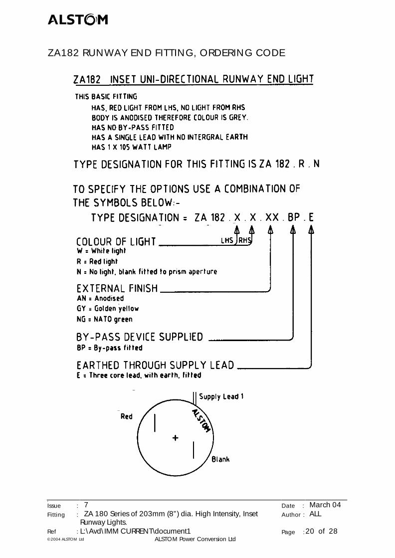
ZA182 RUNWAY END FITTING, ORDERING CODE
abcd
5
Issue : 7 Date : March 04Fitting : ZA 180 Series of 203mm (8”) dia. High Intensity, Inset
Runway Lights.Author : ALL
Ref : L:\Avd\IMM CURRENT\document1 Page :21 of 28©2004 ALSTOM Ltd ALSTOM Power Conversion Ltd
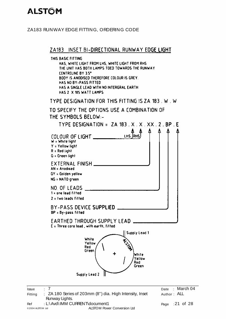
ZA183 RUNWAY EDGE FITTING, ORDERING CODE
abcd
5
Issue : 7 Date : March 04Fitting : ZA 180 Series of 203mm (8”) dia. High Intensity, Inset
Runway Lights.Author : ALL
Ref : L:\Avd\IMM CURRENT\document1 Page :22 of 28©2004 ALSTOM Ltd ALSTOM Power Conversion Ltd
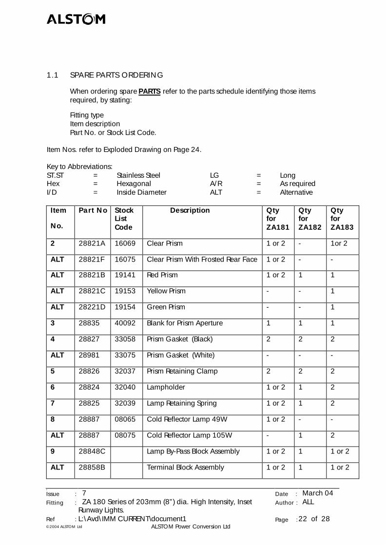
1.1 SPARE PARTS ORDERING
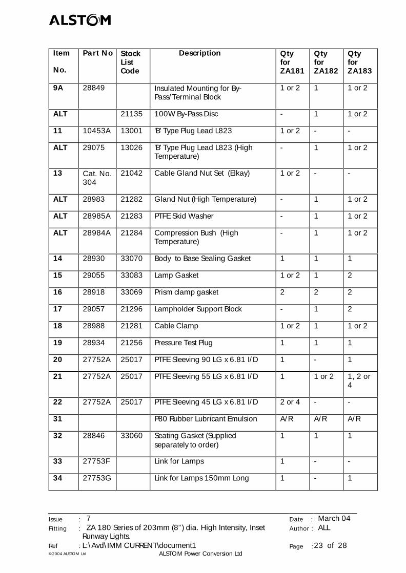
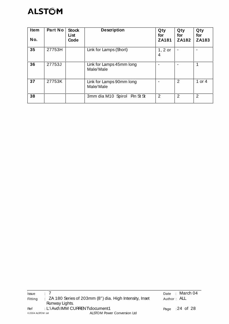
When ordering spare PARTS refer to the parts schedule identifying those itemsrequired, by stating:
Fitting typeItem descriptionPart No. or Stock List Code.
Item Nos. refer to Exploded Drawing on Page 24.
Key to Abbreviations:ST.ST = Stainless Steel LG = LongHex = Hexagonal A/R = As requiredI/D = Inside Diameter ALT = Alternative
Item
No.
Part No StockListCode
Description QtyforZA181
QtyforZA182
QtyforZA183
2 28821A 16069 Clear Prism 1 or 2 - 1or 2
ALT 28821F 16075 Clear Prism With Frosted Rear Face 1 or 2 - -
ALT 28821B 19141 Red Prism 1 or 2 1 1
ALT 28821C 19153 Yellow Prism - - 1
ALT 28221D 19154 Green Prism - - 1
3 28835 40092 Blank for Prism Aperture 1 1 1
4 28827 33058 Prism Gasket (Black) 2 2 2
ALT 28981 33075 Prism Gasket (White) - - -
5 28826 32037 Prism Retaining Clamp 2 2 2
6 28824 32040 Lampholder 1 or 2 1 2
7 28825 32039 Lamp Retaining Spring 1 or 2 1 2
8 28887 08065 Cold Reflector Lamp 49W 1 or 2 - -
ALT 28887 08075 Cold Reflector Lamp 105W - 1 2
9 28848C Lamp By-Pass Block Assembly 1 or 2 1 1 or 2
ALT 28858B Terminal Block Assembly 1 or 2 1 1 or 2
abcd
5
Issue : 7 Date : March 04Fitting : ZA 180 Series of 203mm (8”) dia. High Intensity, Inset
Runway Lights.Author : ALL
Ref : L:\Avd\IMM CURRENT\document1 Page :23 of 28©2004 ALSTOM Ltd ALSTOM Power Conversion Ltd
Item
No.
Part No StockListCode
Description QtyforZA181
QtyforZA182
QtyforZA183
9A 28849 Insulated Mounting for By-Pass/Terminal Block
1 or 2 1 1 or 2
ALT 21135 100W By-Pass Disc - 1 1 or 2
11 10453A 13001 'B' Type Plug Lead L823 1 or 2 - -
ALT 29075 13026 'B' Type Plug Lead L823 (HighTemperature)
- 1 1 or 2
13 Cat. No.304
21042 Cable Gland Nut Set (Elkay) 1 or 2 - -
ALT 28983 21282 Gland Nut (High Temperature) - 1 1 or 2
ALT 28985A 21283 PTFE Skid Washer - 1 1 or 2
ALT 28984A 21284 Compression Bush (HighTemperature)
- 1 1 or 2
14 28930 33070 Body to Base Sealing Gasket 1 1 1
15 29055 33083 Lamp Gasket 1 or 2 1 2
16 28918 33069 Prism clamp gasket 2 2 2
17 29057 21296 Lampholder Support Block - 1 2
18 28988 21281 Cable Clamp 1 or 2 1 1 or 2
19 28934 21256 Pressure Test Plug 1 1 1
20 27752A 25017 PTFE Sleeving 90 LG x 6.81 I/D 1 - 1
21 27752A 25017 PTFE Sleeving 55 LG x 6.81 I/D 1 1 or 2 1, 2 or4
22 27752A 25017 PTFE Sleeving 45 LG x 6.81 I/D 2 or 4 - -
31 P80 Rubber Lubricant Emulsion A/R A/R A/R
32 28846 33060 Seating Gasket (Suppliedseparately to order)
1 1 1
33 27753F Link for Lamps 1 - -
34 27753G Link for Lamps 150mm Long 1 - 1
abcd
5
Issue : 7 Date : March 04Fitting : ZA 180 Series of 203mm (8”) dia. High Intensity, Inset
Runway Lights.Author : ALL
Ref : L:\Avd\IMM CURRENT\document1 Page :24 of 28©2004 ALSTOM Ltd ALSTOM Power Conversion Ltd
Item
No.
Part No StockListCode
Description QtyforZA181
QtyforZA182
QtyforZA183
35 27753H Link for Lamps (Short) 1, 2 or4
- -
36 27753J Link for Lamps 45mm longMale/Male
- - 1
37 27753K Link for Lamps 90mm longMale/Male
- 2 1 or 4
38 3mm dia M10 Spirol Pin St St 2 2 2
abcd
5
Issue : 7 Date : March 04Fitting : ZA 180 Series of 203mm (8”) dia. High Intensity, Inset
Runway Lights.Author : ALL
Ref : L:\Avd\IMM CURRENT\document1 Page :25 of 28©2004 ALSTOM Ltd ALSTOM Power Conversion Ltd
abcd
5
Issue : 7 Date : March 04Fitting : ZA 180 Series of 203mm (8”) dia. High Intensity, Inset
Runway Lights.Author : ALL
Ref : L:\Avd\IMM CURRENT\document1 Page :26 of 28©2004 ALSTOM Ltd ALSTOM Power Conversion Ltd
CIRCUIT DIAGRAMS
abcd
5
Issue : 7 Date : March 04Fitting : ZA 180 Series of 203mm (8”) dia. High Intensity, Inset
Runway Lights.Author : ALL
Ref : L:\Avd\IMM CURRENT\document1 Page :27 of 28©2004 ALSTOM Ltd ALSTOM Power Conversion Ltd
APPENDIX ‘A’ - SAFETY ADVICE
1. COMPLIANCE WITH INSTRUCTIONS IN THIS MANUAL
The purchaser/user is advised to comply with the instructions and information in thismanual and ensure that all personnel to be associated with the apparatus under thiscontract are made familiar with the information contained herein.
2. GUIDANCE NOTES FOR USERS ON THE SAFETY OF PERSONNEL
Every employer shall ensure that his employees are informed, trained and supervisedand use a safe system of work to ensure their safety. He is advised to comply with theinformation provided, to maintain the plant in a safe condition.
Electrically skilled personnel may have to gain access to apparatus which is notcompletely isolated. The burden of responsibility, for the safety of such personnelcarrying out the work, rests on those under whose authority they act.
3. INSTALLATION, OPERATION AND MAINTENANCE
The purchaser/user is advised to ensure that each piece of apparatus supplied to thepurchaser's order is correctly installed, in a suitable location, by technically qualifiedand competent persons experienced in the class of work involved. The rules forensuring the safety of personnel can be summarised as follows:-
During normal use, ensure that plant operators:-
l are fully conversant with all controls, particularly those for emergency shutdown,
l comply with safety warning notices and keep all enclosures shut,
l are trained to recognise signs of mal-operation and know what action to takein the event of trouble or difficulty.
During Maintenance, Testing etc., ensure that only suitably skilled persons arepermitted to carry out work and that they:-
l comply with user's safe system of work and safe working procedures,
l isolate the apparatus completely, where possible, before opening enclosuresand starting work,
l are conversant with the information provided particularly on measures relatingto their safety,
l recognise the hazards which can arise when working on live apparatus andtake all the necessary precautions,
l comply with all local safety regulations.
abcd
5
Issue : 7 Date : March 04Fitting : ZA 180 Series of 203mm (8”) dia. High Intensity, Inset
Runway Lights.Author : ALL
Ref : L:\Avd\IMM CURRENT\document1 Page :28 of 28©2004 ALSTOM Ltd ALSTOM Power Conversion Ltd
4. VOLTAGES GREATER THAN 50V A.C./120V D.C.
The purchaser/user is advised to ensure that apparatus operating on a voltage greaterthan 50V a.c./120V d.c. is isolated and made safe before any work is carried outupon it.
5. APPARATUS SUPPLIED AS LOOSE ITEMS, CHASSIS ETC.
The purchaser/user responsible for installing such apparatus is advised that, whenlive, it could constitute a safety hazard and relevant safety procedures are necessary.
6. ACCESS TO THE APPARATUS DESCRIBED IN THIS MANUAL
It is the purchaser's/user's responsibility to ensure that all personnel obtaining accessto the apparatus are competent and work in accordance with the user's safe systemof work.
Record of Personnel made aware of Safety Advice.
Position/Job Title: ………………………………………………….
Signature: ………………………………………………….
Date: ………………………………………………….