Embed Size (px)
Citation preview

Abbreviated Structure Geotechnical Report
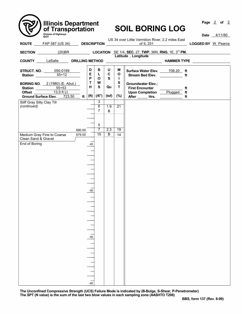
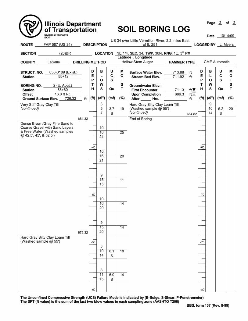
Original Report Date: 5/9/14 Proposed SN: 050-0257 Route: US 34, FAP 587 Revised Date: 7-7-14 Existing SN: 050-0189 Section: (20)BR Geotechnical Engineer: Terry McCleary of McCleary Engineering County: LaSalle Structural Engineer: Lori Sommer of Zroka Engineering PC Contract: 66853 Indicate the proposed structure type, substructure types, and foundation locations (attach plan and elevation drawing): Single span structure, 80.67 ft. in total length from back to back of abutments. The superstructure will be a concrete deck on steel beams and supported by integral abutments with no piers. The factored loadings are estimated to be near 1438 kips and the foundation width was estimated to be near 49 ft. Please refer to the draft TSL drawing for a more accurate picture of what is to be constructed. The recommended foundation is a driven Metal Shell piling or H-piling. See the attached piling discussion. Discuss the existing boring data, existing plans foundation information, new subsurface exploration and need for any additional exploration to be provided with SGR Technical Memo (attach all data and subsurface profile plot): Four borings exist for this structure, two from 1980 and two from 2009. In general, all the borings show similar soil stratification and the 2009 east abutment boring (B-2) is representative of the other borings and is therefore described here. This boring showed soft clay soils down to an approximate depth of 15 ft. where a hard Silty Clay Loam (TILL) was encountered. This soil continues to an approximate depth of 42 ft. where the soils switch to a dense fine Sand to coarse Gravel with N-values as high as 42. This material continues to an approximate depth of 54 ft. where the hard Silty Clay Loam (TILL) was encountered again. The borings ended in this hard TILL material. See the attached boring logs and profile for more detailed descriptions of the subsurface conditions. Each of the existing abutments rest on two rows of driven metal shell piling. The lengths and capacities are shown in the attached pile driving data sheets attached to this abbreviated SGR. At this time I see no need for additional investigation.
Provide the location and maximum height of any new soil fill or magnitude of footing bearing pressure. Estimate the amount and time of the expected settlement. Indicate if further testing, analysis, and/or ground improvement/treatment is necessary: At the time of this report it is my understanding that less than 1.0 ft. of fill will be placed behind the abutments. This fill will likely be in the form of HMA mixtures and aggregate base course. No settlement is expected. Any settlement from the fill placed as widening for the sidewalk is estimated to be minor and will have no effect on the performances of the bridge. No ground improvement beyond normal construction practices is expected at this site therefore no further testing or analysis is proposed at this time. Identify any new cuts or fill slope angles and heights. Estimate the factor of safety against slope failure. Indicate if further testing, analysis or ground improvement/treatment is necessary. Minimal grade change is expected. The end slope on the stream side of the abutment will remain a 1:2(V:H) slope with a slope height near 10 ft. The short term FOS is estimated to be 4.51. We estimate the long term FOS to be 1.53. These factors of safety were estimated using the commercially available software SLIDE 6.0. No further analysis, testing or ground improvement is expected for this project. Indicate at each substructure, the 100-year and 500-year total scour depths in the Hydraulics Report, the non-granular scour depth reduction, the proposed ground surface, and the recommended foundation design scour elevations. No scour was accounted for at the abutments per IDOT policy. The bottom of the west abutment elevation is 720.28 ft. and the bottom of the east abutment is 720.28 ft. These are considered the depth of scour elevations. There are no piers planned for his structure. Determining the seismic soil site class, the seismic performance zone, the 0.2 and 1.0 second design spectral accelerations and indicate if the soils are liquefiable. This site has is in a seismic performance zone, SPZ=1 and has a seismic soil site class of “C”, an SDs = 0.120 and an SD1=0.066. Because of the SPZ a liquefaction analysis was not performed.
cc: Bureau of Bridges and Structures BBS 132 (09/15/11)
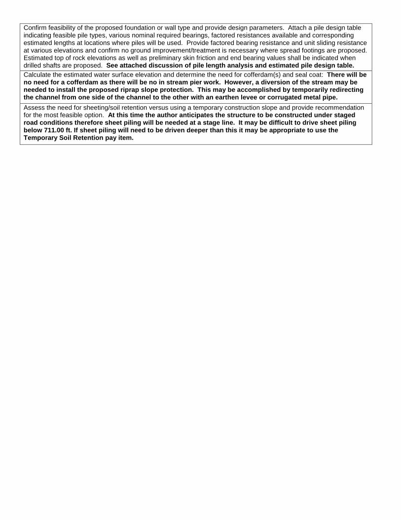
Confirm feasibility of the proposed foundation or wall type and provide design parameters. Attach a pile design table indicating feasible pile types, various nominal required bearings, factored resistances available and corresponding estimated lengths at locations where piles will be used. Provide factored bearing resistance and unit sliding resistance at various elevations and confirm no ground improvement/treatment is necessary where spread footings are proposed. Estimated top of rock elevations as well as preliminary skin friction and end bearing values shall be indicated when drilled shafts are proposed. See attached discussion of pile length analysis and estimated pile design table.
Calculate the estimated water surface elevation and determine the need for cofferdam(s) and seal coat: There will be no need for a cofferdam as there will be no in stream pier work. However, a diversion of the stream may be needed to install the proposed riprap slope protection. This may be accomplished by temporarily redirecting the channel from one side of the channel to the other with an earthen levee or corrugated metal pipe.
Assess the need for sheeting/soil retention versus using a temporary construction slope and provide recommendation for the most feasible option. At this time the author anticipates the structure to be constructed under staged road conditions therefore sheet piling will be needed at a stage line. It may be difficult to drive sheet piling below 711.00 ft. If sheet piling will need to be driven deeper than this it may be appropriate to use the Temporary Soil Retention pay item.

Piling Discussion
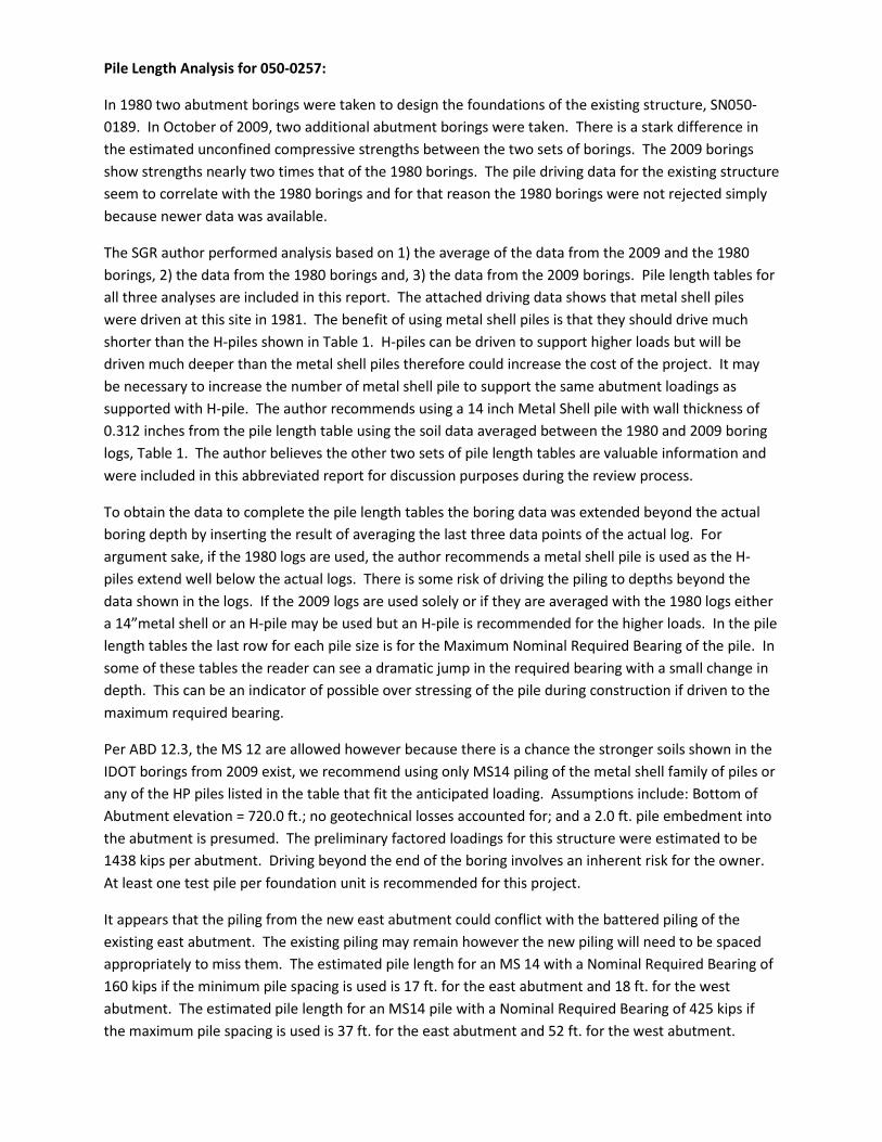
Pile Length Analysis for 050-0257:
In 1980 two abutment borings were taken to design the foundations of the existing structure, SN050-0189. In October of 2009, two additional abutment borings were taken. There is a stark difference in the estimated unconfined compressive strengths between the two sets of borings. The 2009 borings show strengths nearly two times that of the 1980 borings. The pile driving data for the existing structure seem to correlate with the 1980 borings and for that reason the 1980 borings were not rejected simply because newer data was available.
The SGR author performed analysis based on 1) the average of the data from the 2009 and the 1980 borings, 2) the data from the 1980 borings and, 3) the data from the 2009 borings. Pile length tables for all three analyses are included in this report. The attached driving data shows that metal shell piles were driven at this site in 1981. The benefit of using metal shell piles is that they should drive much shorter than the H-piles shown in Table 1. H-piles can be driven to support higher loads but will be driven much deeper than the metal shell piles therefore could increase the cost of the project. It may be necessary to increase the number of metal shell pile to support the same abutment loadings as supported with H-pile. The author recommends using a 14 inch Metal Shell pile with wall thickness of 0.312 inches from the pile length table using the soil data averaged between the 1980 and 2009 boring logs, Table 1. The author believes the other two sets of pile length tables are valuable information and were included in this abbreviated report for discussion purposes during the review process.
To obtain the data to complete the pile length tables the boring data was extended beyond the actual boring depth by inserting the result of averaging the last three data points of the actual log. For argument sake, if the 1980 logs are used, the author recommends a metal shell pile is used as the H-piles extend well below the actual logs. There is some risk of driving the piling to depths beyond the data shown in the logs. If the 2009 logs are used solely or if they are averaged with the 1980 logs either a 14”metal shell or an H-pile may be used but an H-pile is recommended for the higher loads. In the pile length tables the last row for each pile size is for the Maximum Nominal Required Bearing of the pile. In some of these tables the reader can see a dramatic jump in the required bearing with a small change in depth. This can be an indicator of possible over stressing of the pile during construction if driven to the maximum required bearing.
Per ABD 12.3, the MS 12 are allowed however because there is a chance the stronger soils shown in the IDOT borings from 2009 exist, we recommend using only MS14 piling of the metal shell family of piles or any of the HP piles listed in the table that fit the anticipated loading. Assumptions include: Bottom of Abutment elevation = 720.0 ft.; no geotechnical losses accounted for; and a 2.0 ft. pile embedment into the abutment is presumed. The preliminary factored loadings for this structure were estimated to be 1438 kips per abutment. Driving beyond the end of the boring involves an inherent risk for the owner. At least one test pile per foundation unit is recommended for this project.
It appears that the piling from the new east abutment could conflict with the battered piling of the existing east abutment. The existing piling may remain however the new piling will need to be spaced appropriately to miss them. The estimated pile length for an MS 14 with a Nominal Required Bearing of 160 kips if the minimum pile spacing is used is 17 ft. for the east abutment and 18 ft. for the west abutment. The estimated pile length for an MS14 pile with a Nominal Required Bearing of 425 kips if the maximum pile spacing is used is 37 ft. for the east abutment and 52 ft. for the west abutment.

Draft TSL Drawing


Soil Profile

El. 720.28
Boring 1
Sta. 54+55
14' Lt.
Elev. 726.32
Augered Bit. shldr.,brn. coarse Agg. fill
Very stiff blk. Silty Clay fill w/conc. debris
(large pieces, auger refusal-moved 5' west,
old bridge?)
Stiff blk./gray Silty Clay Loam/Silty Loam
alluvial slackwater deposits
Medium gray Loamy Fine Sand to coarse Gravel w/free water
Hard gray Silty Clay Loam Till
Hard gray Clay Till
Very stiff gray Clay Till
Hard to very stiff gray Silt, Silty Clay & Clay interbedded >1" thick
Medium gray Silty Clay Loam/Clay Till
Very loose gray fine to coarse Sand
Hard gray Silty Clay Loam Till
Hard brn. Silty Clay Loam Till
End of Boring
41-3.0P-25
9-3.0P-24
5-2.0P-40
5-1.5P-26
4-1.5P-19
11- -15
11-4.5S-15
12-4.8S-14
17-5.4S-17
19-5.6S-17
17-5.4S-17
8-3.3B-19
7-3.3B-21
7-3.3B-21
19-4.2S-21
9-3.1S-21
6-1.2B-19
6-1.7B-18
2- -17
6- -22
12-4.1B-18
14-4.1B-18
17-4.6B-19
28-6.1S-16
18-4.1S-14
28-6.6S-13
22-6.2S-12
24-6.4S-12
Boring 2
Sta. 55+60
16' Rt.
Elev. 726.32
Augered Bit. Shldr, brn. coarse Agg. Fill, white Silica Sand Fill
Medium white Silica Sand Fill w/gray Clay pieces
Soft gray/green Silty Clay/Silty Clay Loam alluvial deposits w/Silt & Sand layers
Hard gray Silty Clay Loam Till
Hard gray Clay Till
Very stiff Gray Clay Till
Dense brn./gray fine Sand to coarse Gravel w/Sand layers & free water
(washed samples @ 42.5',45', & 52.5')
Hard gray Silty Clay Loam Till
(washed sample @ 55')
End of Boring
9- -17
3-0.5P-28
4-1.0P-31
7-1.0P-19
8-4.1B-14
16-5.4S-20
19-6.1S-15
19-5.9S-18
17-5.7S-16
16-5.4S-28
14-4.2S-29
10-3.6B-22
9-3.4B-23
11-3.7B-23
12-3.7B-19
42- -25
37- -20
30- -11
36- -14
35- -14
24-6.1S-18
26-6.0S-14
RouteSection County
Scale =______
Sheet ____ of _______Sta. ____________ to Sta.________
Bridge number: __________________________
Designed by:
Drawn by:
Checked by:
Date:
Date:
Date:
ME
Clearyngineering
cMLL
3/27/14
1 1
U.S. 34 Bridge East of Mendota
LaSalle
050-0189
US 34

Pile Length Tables
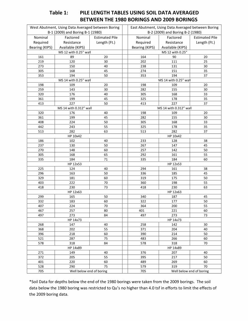
Table 1: PILE LENGTH TABLES USING SOIL DATA AVERAGED BETWEEN THE 1980 BORINGS AND 2009 BORINGS
*Soil Data for depths below the end of the 1980 borings were taken from the 2009 borings. The soil data below the 1980 boring was restricted to Qu’s no higher than 4.0 tsf in efforts to limit the effects of the 2009 boring data.
West Abutment, Using Data Averaged between Boring B-1 (2009) and Boring B-1 (1980)
East Abutment, Using Data Averaged between Boring B-2 (2009) and Boring B-2 (1980)
Nominal Required
Bearing (KIPS)
Factored Resistance
Available (KIPS)
Estimated Pile Length (Ft.)
Nominal Required
Bearing (KIPS)
Factored Resistance
Available (KIPS)
Estimated Pile Length (Ft.)
MS 12 with 0.25” wall MS 12 with 0.25” 161 89 20 164 90 20 219 120 30 202 111 25 273 150 40 238 131 30 305 168 45 274 151 35 353 194 50 353 194 37
MS 14 with 0.25” wall MS 14 with 0.25” wall 198 109 20 198 109 20 259 143 30 282 155 30 320 176 40 305 168 33 361 199 45 325 178 35 413 227 50 413 227 37
MS 14 with 0.312” wall MS 14 with 0.312” wall 320 176 40 198 109 20 361 199 45 282 155 30 408 224 50 305 168 33 442 243 55 325 178 35 513 282 63 513 282 37
HP 10x42 HP 10x42 186 102 40 233 128 38 237 130 50 267 147 45 270 148 60 257 142 50 305 168 65 292 161 55 335 184 71 335 184 60
HP 12x53 HP 12x53 225 124 40 294 161 38 296 163 50 336 185 45 329 181 60 319 175 50 403 222 70 360 198 55 418 230 73 418 230 63
HP 12x63 HP 12x63 299 165 50 340 187 45 332 183 60 322 177 50 407 224 70 364 200 55 467 257 80 401 221 60 497 273 84 497 273 73
HP 14x73 HP 14x73 268 147 40 258 142 30 368 202 55 371 204 40 396 218 60 390 214 50 521 287 75 483 266 60 578 318 84 578 318 70
HP 14x89 HP 14x89 271 149 40 376 207 40 372 205 55 395 217 50 401 220 60 489 269 60 528 290 75 579 319 70 705 Well below end of boring 705 Well below end of boring

Table 2: PILE LENGTH TABLES USING SOIL DATA from Borings taken in 2009
*Below the bottom of the boring data.
West Abutment, Using Boring B-1 (2009) East Abutment, Using Boring B-2 (2009) Nominal Required
Bearing (KIPS)
Factored Resistance Available
(KIPS)
Estimated Pile Length
(Ft.)
Nominal Required
Bearing (KIPS)
Factored Resistance Available
(KIPS)
Estimated Pile Length
(Ft.)
MS 12 with 0.25” wall MS 12 with 0.25” 250 138 30 171 94 20 293 161 35 209 115 25 312 172 41 248 137 30 341 188 45 302 166 36 353 194 48 353 194 37
MS 14 with 0.25” wall MS 14 with 0.25” wall 298 164 30 209 115 20 347 191 35 251 138 25 367 202 41 295 162 30 404 222 45 359 197 36 413 227 47 413 227 37
MS 14 with 0.312” wall MS 14 with 0.312” wall 298 164 30 209 115 20 347 191 35 251 138 25 367 202 41 295 162 30 404 222 45 359 197 36 513 283 54 513 283 37
HP 10x42 HP 10x42 177 98 30 246 135 40 213 117 41 269 148 45 262 144 50 275 151 50 314 173 55 314 173 56 335 185 59 335 185 59*
HP 12x53 HP 12x53 221 122 30 308 170 40 260 143 41 339 187 45 324 178 50 345 190 50 391 215 55 392 215 56 418 229 59 418 229 59*
HP 12x63 HP 12x63 223 123 30 312 171 40 262 144 41 343 189 45 327 180 50 348 192 50 388 213 58 396 218 56 497 273 67 497 273 68*
HP 14x73 HP 14x73 272 149 30 320 176 35 313 172 41 381 210 40 396 218 50 427 235 50 468 257 58 482 265 56 578 318 66 578 318 66*
HP 14x89 HP 14x89 317 174 41 324 178 35 401 221 50 387 213 40 551 303 61 433 238 50 645 355 71 489 269 56 705 387 77* 705 387 80*

Table 2: PILE LENGTH TABLES USING SOIL DATA from Borings taken in 1980
*Below the bottom of the boring data.
West Abutment, Using Boring B-1 (1980) East Abutment, Using Boring B-2 (1980) Nominal Required
Bearing (KIPS)
Factored Resistance Available
(KIPS)
Estimated Pile Length
(Ft.)
Nominal Required
Bearing (KIPS)
Factored Resistance Available
(KIPS)
Estimated Pile Length
(Ft.)
MS 12 with 0.25” wall MS 12 with 0.25” 188 104 31 198 109 31 223 123 36 229 126 36 347 191 41 267 147 42 287 158 50 296 163 48* 353 194 51 353 194 58*
MS 14 with 0.25” wall MS 14 with 0.25” wall 265 146 36 271 149 36 427 235 41** 315 173 42 363 200 45 349 192 48* 338 186 50 382 210 53* 413 227 51 413 227 58*
MS 14 with 0.312” wall MS 14 with 0.312” wall 265 146 36 271 149 36 427 235 41 315 173 42 363 200 45 349 192 48* 338 186 50 416 229 58* 513 283 51 513 283 72*
HP 12x53 HP 12x53 331 182 80* 229 126 43 339 187 85* 276 152 53* 348 191 90* 322 177 63* 356 196 95* 368 202 73* 418 229 >100* 418 229 84*
HP 12x63 HP 12x63 334 184 80* 255 140 48* 343 189 85* 301 166 58* 351 193 90* 348 191 68* 360 198 95* 395 217 78* 497 Well below bottom of boring 497 Well below bottom of boring
HP 14x73 HP 14x73 276 152 50 252 138 38 356 196 55 305 168 48* 367 202 60* 360 198 58* 397 218 75* 415 228 68* 578 Well below bottom of boring 578 Well below bottom of boring
HP 14x89 HP 14x89 280 154 50 284 156 42 361 198 55 309 170 48* 372 205 60* 337 185 53* 402 221 75* 392 215 63* 705 Well below bottom of boring 705 Well below bottom of boring

Complete Pile Length Output Using Boring Data Averaged Between
1980 and 2009 Logs

Pile Design Table for West abut. utilizing Boring #1 (Ave. of 1980 & 2009)Nominal Factored Estimated Nominal Factored Estimated Nominal Factored EstimatedRequired Resistance Pile Required Resistance Pile Required Resistance PileBearing Available Length Bearing Available Length Bearing Available Length(Kips) (Kips) (Ft.) (Kips) (Kips) (Ft.) (Kips) (Kips) (Ft.)
Metal Shell 12"Φ w/.179" walls Steel HP 10 X 57 Steel HP 14 X 73161 89 20 159 87 30 130 71 18172 94 23 171 94 33 167 92 20195 107 25 189 104 40 199 110 23204 112 28 191 105 43 221 122 28219 120 30 198 109 45 235 129 30236 130 33 242 133 50 253 139 33
Metal Shell 12"Φ w/.25" walls 254 140 55 268 147 40161 89 20 272 150 58 269 148 43172 94 23 275 151 60 283 156 45195 107 25 298 164 63 366 201 50204 112 28 312 171 65 368 202 55219 120 30 323 178 68 396 218 60236 130 33 337 185 70 434 239 63261 143 35 349 192 73 453 249 65273 150 38 362 199 75 469 258 68273 150 40 374 206 78 487 268 70284 156 43 387 213 80 503 277 73305 168 45 400 220 83 521 287 75
Metal Shell 14"Φ w/.25" walls 413 227 85 539 297 78165 91 18 426 234 88 557 307 80198 109 20 439 241 90 575 316 83207 114 23 452 248 93 Steel HP 14 X 89234 129 25 Steel HP 12 X 53 133 73 18242 133 28 165 91 23 171 94 20259 143 30 181 99 28 203 112 23279 154 33 192 106 30 224 123 28310 171 35 207 114 33 238 131 30320 176 40 225 124 40 256 141 33333 183 43 226 124 43 271 149 40361 199 45 236 130 45 272 149 43
Metal Shell 14"Φ w/.312" walls 296 163 50 286 157 45165 91 18 304 167 55 371 204 50198 109 20 327 180 58 372 205 55207 114 23 329 181 60 401 220 60234 129 25 358 197 63 439 242 63242 133 28 374 206 65 459 252 65259 143 30 388 213 68 474 261 68279 154 33 403 222 70 493 271 70310 171 35 417 230 73 509 280 73320 176 40 Steel HP 12 X 63 528 290 75333 183 43 141 77 20 546 300 78361 199 45 168 93 23 564 310 80
Steel HP 8 X 36 182 100 28 582 320 83157 86 45 194 107 30 600 330 85186 102 50 209 115 33 618 340 88200 110 55 227 125 40 637 350 90213 117 58 228 125 43 655 360 93217 120 60 238 131 45 Steel HP 14 X 102233 128 63 299 165 50 136 75 18244 134 65 307 169 55 174 95 20254 140 68 330 182 58 205 113 23265 146 70 332 183 60 227 125 28275 151 73 361 199 63 241 132 30285 157 75 378 208 65 259 142 33
Steel HP 10 X 42 391 215 68 274 151 40156 86 30 407 224 70 274 151 43167 92 33 421 232 73 289 159 45186 102 40 436 240 75 376 207 50187 103 43 452 248 78 376 207 55194 107 45 467 257 80 405 223 60237 130 50 482 265 83 445 245 63249 137 55 Steel HP 12 X 74 464 255 65266 147 58 143 79 20 480 264 68270 148 60 170 94 23 499 274 70291 160 63 185 102 28 515 283 73305 168 65 197 108 30 534 294 75316 174 68 212 117 33 552 304 78329 181 70 230 126 40 571 314 80
231 127 43 589 324 83241 133 45 607 334 85304 167 50 626 344 88311 171 55 644 354 90335 184 58 662 364 93336 185 60 Steel HP 14 X 117366 201 63 140 77 18383 211 65 177 98 20397 218 68 209 115 23413 227 70 230 126 28427 235 73 244 134 30442 243 75 262 144 33458 252 78 277 152 40473 260 80 277 153 43489 269 83 292 161 45504 277 85 381 209 55520 286 88 410 225 60535 294 90 450 247 63551 303 93 470 258 65
Steel HP 12 X 84 486 267 68146 80 20 505 277 70172 95 23 521 287 73188 103 28 540 297 75200 110 30 559 307 78215 118 33 577 317 80232 128 40 596 328 83234 128 43 614 338 85244 134 45 633 348 88309 170 50 651 358 90316 174 55 670 368 93340 187 58 Precast 14"x 14"341 188 60 162 89 15371 204 63 210 115 18388 214 65 252 139 20402 221 68 264 145 23418 230 70 Timber Pile 433 238 73 147 81 23448 247 75464 255 78480 264 80496 273 83511 281 85527 290 88543 298 90558 307 93

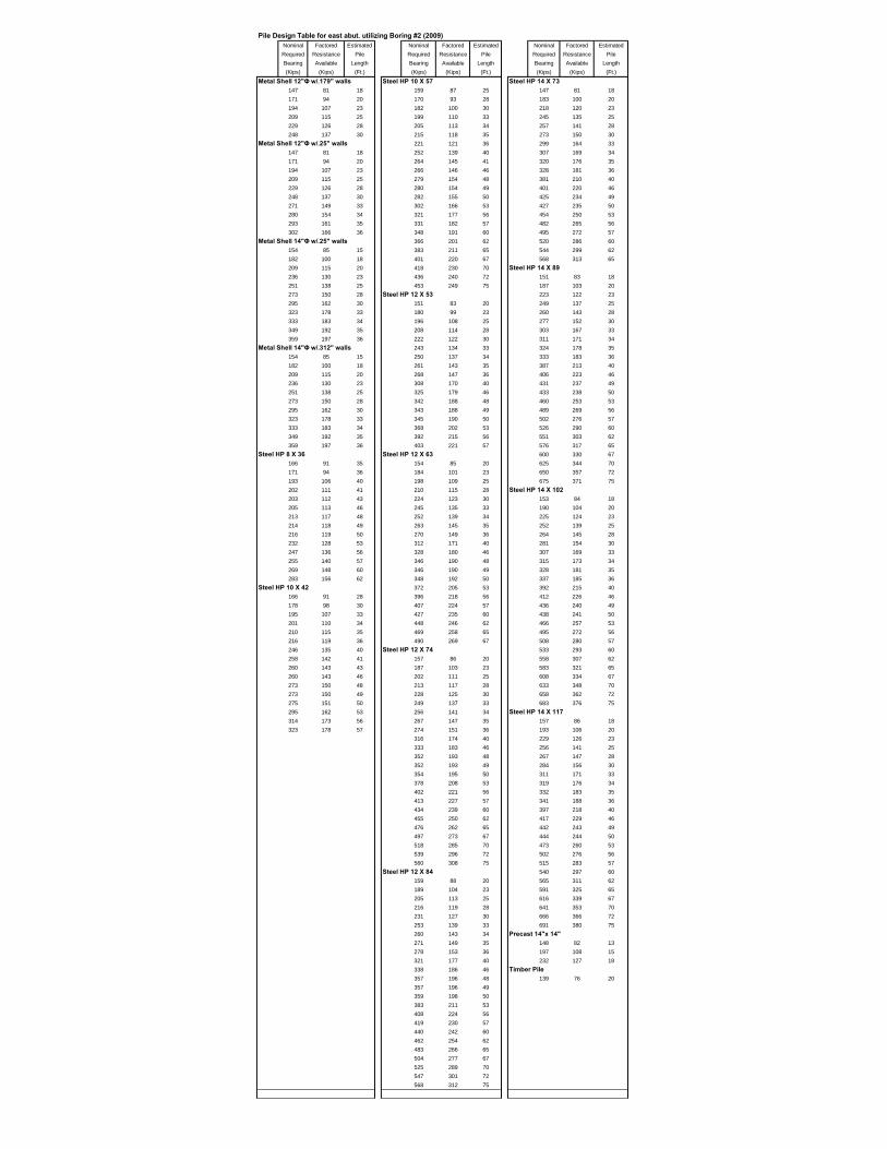
Pile Design Table for east abut. utilizing Boring #2 (Ave. of 1980 & 2009)Nominal Factored Estimated Nominal Factored Estimated Nominal Factored EstimatedRequired Resistance Pile Required Resistance Pile Required Resistance PileBearing Available Length Bearing Available Length Bearing Available Length(Kips) (Kips) (Ft.) (Kips) (Kips) (Ft.) (Kips) (Kips) (Ft.)
Metal Shell 12"Φ w/.179" walls Steel HP 10 X 57 Steel HP 14 X 73164 90 20 162 89 28 156 86 18186 102 23 173 95 30 190 105 20202 111 25 181 99 32 219 121 23220 121 28 187 103 33 226 124 25238 131 30 195 107 34 242 133 28249 137 32 198 109 35 258 142 30
Metal Shell 12"Φ w/.25" walls 205 113 37 268 147 32164 90 20 239 131 38 278 153 33186 102 23 245 134 40 289 159 34202 111 25 258 142 41 292 161 35220 121 28 260 143 44 302 166 37238 131 30 263 145 50 365 201 38249 137 32 282 155 53 371 204 40257 141 33 298 164 55 390 214 50268 148 34 314 173 58 416 229 53274 151 35 330 182 60 439 241 55285 157 37 346 190 63 461 254 58
Metal Shell 14"Φ w/.25" walls 362 199 65 483 266 60144 79 15 378 208 68 505 278 63176 97 18 394 217 70 528 290 65198 109 20 410 226 73 550 303 68223 123 23 Steel HP 12 X 53 572 315 70240 132 25 157 87 20 Steel HP 14 X 89262 144 28 175 96 23 159 87 18282 155 30 183 100 25 194 107 20295 162 32 197 108 28 223 122 23305 168 33 210 116 30 229 126 25318 175 34 219 120 32 245 135 28325 178 35 227 125 33 261 144 30337 185 37 236 130 34 271 149 32
Metal Shell 14"Φ w/.312" walls 239 132 35 281 155 33144 79 15 248 136 37 292 161 34176 97 18 294 161 38 296 163 35198 109 20 299 165 40 306 168 37223 123 23 317 174 41 370 204 38240 132 25 318 175 44 376 207 40262 144 28 319 175 50 395 217 50282 155 30 341 188 53 422 232 53295 162 32 360 198 55 444 244 55305 168 33 379 208 58 467 257 58318 175 34 398 219 60 489 269 60325 178 35 416 229 63 512 281 63337 185 37 Steel HP 12 X 63 534 294 65
Steel HP 8 X 36 160 88 20 557 306 68160 88 37 177 98 23 579 319 70182 100 38 185 101 25 602 331 73187 103 40 199 109 28 Steel HP 14 X 102196 108 41 212 117 30 161 89 18199 110 44 221 122 32 196 108 20204 112 46 229 126 33 226 124 23205 112 50 238 131 34 232 127 25220 121 53 242 133 35 248 137 28233 128 55 250 138 37 264 145 30245 135 58 297 163 38 275 151 32258 142 60 303 166 40 285 157 33271 149 63 321 176 41 296 163 34284 156 65 322 177 44 299 165 35
Steel HP 10 X 42 322 177 50 310 170 37158 87 28 345 190 53 375 206 38169 93 30 364 200 55 381 209 40177 97 32 383 210 58 400 220 50183 101 33 401 221 60 427 235 53191 105 34 420 231 63 450 247 55194 107 35 439 242 65 472 260 58201 111 37 458 252 68 495 272 60233 128 38 477 263 70 518 285 63239 131 40 496 273 73 541 297 65252 138 41 Steel HP 12 X 74 563 310 68254 140 44 163 90 20 586 322 70257 142 50 180 99 23 609 335 73276 152 53 187 103 25 Steel HP 14 X 117292 161 55 202 111 28 165 91 18307 169 58 215 119 30 199 110 20323 178 60 224 123 32 229 126 23
233 128 33 235 129 25242 133 34 251 138 28245 135 35 268 147 30254 140 37 278 153 32301 166 38 289 159 33307 169 40 300 165 34326 179 41 303 167 35327 180 50 314 173 37350 192 53 380 209 38369 203 55 386 212 40388 213 58 405 223 50407 224 60 432 238 53426 235 63 455 250 55446 245 65 478 263 58465 256 68 501 276 60484 266 70 524 288 63503 277 73 547 301 65
Steel HP 12 X 84 570 314 68165 91 20 593 326 70183 101 23 616 339 73190 105 25 Precast 14"x 14"205 113 28 149 82 13219 120 30 183 101 15228 125 32 225 124 18236 130 33 252 139 20245 135 34 Timber Pile 249 137 35 141 78 20258 142 37306 168 38312 172 40331 182 41331 182 50355 195 53374 206 55394 216 58413 227 60432 238 63452 249 65471 259 68491 270 70510 281 73

Complete Pile Length Output Using Boring Data from 1980 Logs

Pile Design Table for west abut. utilizing Boring #1 (1980)Nominal Factored Estimated Nominal Factored Estimated Nominal Factored EstimatedRequired Resistance Pile Required Resistance Pile Required Resistance PileBearing Available Length Bearing Available Length Bearing Available Length(Kips) (Kips) (Ft.) (Kips) (Kips) (Ft.) (Kips) (Kips) (Ft.)
Metal Shell 12"Φ w/.179" walls Steel HP 10 X 57 Steel HP 14 X 73
154 85 23 164 90 36 155 85 21172 95 26 167 92 38 182 100 23178 98 28 180 99 43 187 103 28188 104 31 181 99 44 194 107 31202 111 33 182 100 45 210 116 33223 123 36 182 100 46 243 133 38233 128 38 183 101 48 261 144 43
Metal Shell 12"Φ w/.25" walls 187 103 49 262 144 44154 85 23 191 105 50 264 145 45172 95 26 194 107 51 264 145 46178 98 28 231 127 52 266 146 48188 104 31 232 128 53 271 149 49202 111 33 233 128 54 276 152 50223 123 36 235 129 55 281 155 51233 128 38 236 130 55 350 192 52276 152 48 243 134 60 352 193 53282 155 49 250 138 65 354 195 54287 158 50 257 141 70 356 196 55292 161 51 264 145 75 357 196 55
Metal Shell 14"Φ w/.25" walls 272 149 80 367 202 60127 70 16 279 153 85 377 207 65169 93 18 286 157 90 387 213 70178 98 21 293 161 95 397 218 75185 102 23 Steel HP 12 X 53 407 224 80205 113 26 161 88 31 417 229 85210 116 28 173 95 33 427 235 90222 122 31 199 109 36 437 241 95238 131 33 200 110 38 Steel HP 14 X 89
265 146 36 216 119 43 159 87 21275 151 38 217 119 44 184 101 23
Metal Shell 14"Φ w/.312" walls 218 120 45 189 104 28127 70 16 219 120 46 197 108 31169 93 18 220 121 48 213 117 33178 98 21 224 123 49 246 135 38185 102 23 229 126 50 265 146 43205 113 26 233 128 51 265 146 44210 116 28 282 155 52 267 147 45222 122 31 284 156 53 268 147 46238 131 33 286 157 54 269 148 48265 146 36 287 158 55 275 151 49275 151 38 288 159 55 280 154 50326 179 48 297 163 60 285 157 51332 182 49 305 168 65 354 195 52338 186 50 314 173 70 357 196 53344 189 51 322 177 75 359 197 54
Steel HP 8 X 36 331 182 80 361 198 55153 84 51 339 187 85 362 199 55177 97 52 348 191 90 372 205 60178 98 53 356 196 95 382 210 65179 98 54 Steel HP 12 X 63 392 216 70180 99 55 162 89 31 402 221 75181 99 55 175 96 33 413 227 80186 103 60 201 110 36 423 233 85192 106 65 202 111 38 433 238 90198 109 70 218 120 43 443 244 95204 112 75 219 120 44 Steel HP 14 X 102
210 115 80 220 121 45 161 89 21215 118 85 221 121 46 187 103 23221 122 90 222 122 48 191 105 28227 125 95 226 125 49 199 109 31
Steel HP 10 X 42 231 127 50 215 119 33163 90 38 235 129 51 249 137 38176 97 43 285 157 52 268 147 43177 97 44 287 158 53 269 148 44178 98 45 289 159 54 270 148 45178 98 46 290 160 55 271 149 46180 99 48 291 160 55 273 150 48183 101 49 300 165 60 278 153 49187 103 50 308 170 65 283 156 50190 105 51 317 174 70 288 159 51225 124 52 326 179 75 359 198 52227 125 53 334 184 80 361 199 53228 125 54 343 189 85 363 200 54229 126 55 351 193 90 365 201 55230 127 55 360 198 95 367 202 55237 130 60 Steel HP 12 X 74 377 207 60244 134 65 164 90 31 387 213 65251 138 70 178 98 33 397 219 70258 142 75 204 112 36 408 224 75265 146 80 205 113 38 418 230 80273 150 85 221 122 43 428 236 85280 154 90 222 122 44 439 241 90287 158 95 223 123 45 449 247 95
224 123 46 Steel HP 14 X 117
225 124 48 164 90 21230 126 49 190 104 23234 129 50 194 107 28238 131 51 201 111 31290 159 52 218 120 33291 160 53 252 138 38293 161 54 271 149 43295 162 55 272 149 44296 163 55 273 150 45305 167 60 274 151 46313 172 65 276 152 48322 177 70 281 155 49331 182 75 286 157 50339 187 80 292 160 51348 191 85 364 200 52357 196 90 366 201 53365 201 95 368 203 54
Steel HP 12 X 84 370 204 55160 88 28 371 204 55167 92 31 382 210 60180 99 33 392 216 65207 114 36 403 221 70208 114 38 413 227 75224 123 43 423 233 80225 124 44 434 239 85226 124 45 444 244 90227 125 46 455 250 95228 126 48 Precast 14"x 14"
233 128 49 162 89 16237 130 50 215 118 18242 133 51 226 124 21294 162 52 236 130 23296 163 53 261 144 26298 164 54 Timber Pile
300 165 55 137 75 23300 165 55309 170 60318 175 65327 180 70336 185 75344 189 80353 194 85362 199 90371 204 95

Pile Design Table for east abut. utilizing Boring #2 (1980)Nominal Factored Estimated Nominal Factored Estimated Nominal Factored EstimatedRequired Resistance Pile Required Resistance Pile Required Resistance PileBearing Available Length Bearing Available Length Bearing Available Length(Kips) (Kips) (Ft.) (Kips) (Kips) (Ft.) (Kips) (Kips) (Ft.)
Metal Shell 12"Φ w/.179" walls Steel HP 10 X 57 Steel HP 14 X 73154 85 23 166 91 36 141 78 18167 92 26 173 95 38 168 92 21181 99 28 191 105 43 173 95 23198 109 31 211 116 48 182 100 26213 117 33 230 127 53 194 106 28229 126 36 250 137 58 215 118 31241 133 38 269 148 63 230 126 33
Metal Shell 12"Φ w/.25" walls 289 159 68 245 134 36154 85 23 309 170 73 252 138 38167 92 26 328 180 78 278 153 43181 99 28 348 191 83 305 168 48198 109 31 367 202 88 333 183 53213 117 33 387 213 93 360 198 58229 126 36 407 224 98 387 213 63241 133 38 426 234 103 415 228 68267 147 42 446 245 108 442 243 73268 147 43 Steel HP 12 X 53 469 258 78296 163 48 159 87 28 497 273 83325 179 53 175 96 31 524 288 88
Metal Shell 14"Φ w/.25" walls 188 103 33 551 303 93143 79 18 201 110 36 Steel HP 14 X 89173 95 21 208 114 38 144 79 18184 101 23 229 126 43 171 94 21198 109 26 253 139 48 175 96 23214 118 28 276 152 53 184 101 26235 129 31 299 164 58 196 108 28253 139 33 322 177 63 217 120 31271 149 36 345 190 68 232 128 33285 157 38 368 202 73 248 136 36315 173 42 391 215 78 255 140 38315 173 43 414 228 83 281 155 43349 192 48 Steel HP 12 X 63 309 170 48382 210 53 160 88 28 337 185 53
Metal Shell 14"Φ w/.312" walls 177 97 31 364 200 58143 79 18 190 104 33 392 215 63173 95 21 202 111 36 419 231 68184 101 23 210 115 38 447 246 73198 109 26 232 127 43 475 261 78214 118 28 255 140 48 502 276 83235 129 31 278 153 53 530 292 88253 139 33 301 166 58 558 307 93271 149 36 325 179 63 585 322 98285 157 38 348 191 68 613 337 103315 173 42 371 204 73 641 352 108315 173 43 395 217 78 668 368 113349 192 48 418 230 83 696 383 118382 210 53 441 243 88 Steel HP 14 X 102416 229 58 464 255 93 145 80 18449 247 63 488 268 98 173 95 21482 265 68 Steel HP 12 X 74 177 98 23
Steel HP 8 X 36 162 89 28 187 103 26166 91 48 180 99 31 199 109 28181 100 53 193 106 33 220 121 31197 108 58 205 113 36 235 129 33213 117 63 213 117 38 251 138 36228 126 68 235 129 43 258 142 38244 134 73 258 142 48 285 157 43260 143 78 282 155 53 313 172 48275 151 83 306 168 58 340 187 53
Steel HP 10 X 42 329 181 63 368 203 58162 89 36 353 194 68 396 218 63169 93 38 376 207 73 424 233 68187 103 43 400 220 78 452 249 73206 113 48 423 233 83 480 264 78225 124 53 447 246 88 508 279 83245 135 58 471 259 93 536 295 88264 145 63 494 272 98 564 310 93283 156 68 518 285 103 592 326 98302 166 73 541 298 108 620 341 103321 177 78 565 311 113 648 356 108
588 324 118 676 372 113Steel HP 12 X 84 704 387 118
165 91 28 732 402 123182 100 31 760 418 128195 107 33 787 433 133208 115 36 Steel HP 14 X 117216 119 38 147 81 18238 131 43 175 96 21262 144 48 180 99 23286 157 53 189 104 26310 170 58 201 111 28334 183 63 223 123 31357 197 68 238 131 33381 210 73 254 140 36405 223 78 261 144 38429 236 83 288 158 43453 249 88 316 174 48477 262 93 344 189 53501 275 98 373 205 58524 288 103 401 221 63548 302 108 429 236 68572 315 113 457 252 73596 328 118 486 267 78620 341 123 514 283 83644 354 128 542 298 88
570 314 93599 329 98627 345 103655 360 108683 376 113711 391 118740 407 123768 422 128796 438 133824 453 138853 469 143
Precast 14"x 14"166 92 16182 100 18220 121 21234 129 23252 139 26
Timber Pile 141 78 23

Complete Pile Length Output Using Boring Data from 2009 Logs

Pile Design Table for west abut. utilizing Boring #1 (2009)Nominal Factored Estimated Nominal Factored Estimated Nominal Factored EstimatedRequired Resistance Pile Required Resistance Pile Required Resistance PileBearing Available Length Bearing Available Length Bearing Available Length(Kips) (Kips) (Ft.) (Kips) (Kips) (Ft.) (Kips) (Kips) (Ft.)
Metal Shell 12"Φ w/.179" walls Steel HP 10 X 57 Steel HP 14 X 73152 83 18 154 85 25 154 85 18179 98 20 168 92 28 191 105 20203 111 23 182 100 30 226 125 23210 116 25 204 112 38 233 128 25230 127 28 213 117 43 252 139 28250 138 30 220 121 45 272 149 30
Metal Shell 12"Φ w/.25" walls 251 138 48 292 161 38152 83 18 268 147 50 300 165 43179 98 20 289 159 53 314 172 45203 111 23 319 175 58 374 205 48210 116 25 363 200 61 396 218 50230 127 28 381 209 63 429 236 53250 138 30 394 217 66 468 257 58278 153 33 412 226 68 543 299 61293 161 35 431 237 71 568 312 63296 163 38 441 242 72 Steel HP 14 X 89312 172 41 Steel HP 12 X 53 158 87 18320 176 43 157 87 20 195 107 20341 188 45 187 103 23 231 127 23351 193 48 188 104 25 236 130 25
Metal Shell 14"Φ w/.25" walls 205 113 28 256 141 28149 82 15 221 122 30 275 151 30186 102 18 243 134 38 295 162 38218 120 20 252 139 43 303 167 43245 135 23 262 144 45 317 174 45251 138 25 305 168 48 378 208 48274 151 28 324 178 50 401 221 50298 164 30 350 193 53 434 239 53332 182 33 384 211 58 474 260 58347 191 35 Steel HP 12 X 63 551 303 61347 191 38 161 89 20 575 316 63367 202 41 190 105 25 592 326 66376 207 43 207 114 28 617 339 68404 222 45 223 123 30 645 355 71
Metal Shell 14"Φ w/.312" walls 246 135 38 658 362 72149 82 15 254 140 43 678 373 74186 102 18 264 145 45 698 384 76218 120 20 308 169 48 Steel HP 14 X 102245 135 23 327 180 50 160 88 18251 138 25 354 194 53 197 109 20274 151 28 388 213 58 234 128 23298 164 30 446 245 61 240 132 25332 182 33 467 257 63 259 143 28347 191 35 482 265 66 279 153 30347 191 38 Steel HP 12 X 74 299 164 38367 202 41 163 90 20 306 168 43376 207 43 193 106 25 321 176 45404 222 45 210 116 28 383 211 48417 229 48 227 125 30 406 224 50445 245 50 249 137 38 440 242 53478 263 53 257 142 43 479 264 58
Steel HP 8 X 36 268 147 45 558 307 61162 89 38 312 172 48 583 320 63170 94 43 332 183 50 600 330 66175 96 45 359 197 53 624 343 68195 107 48 394 217 58 653 359 71208 114 50 453 249 61 666 367 72224 123 53 474 261 63 686 378 74248 136 55 489 269 66 706 388 76249 137 58 511 281 68 726 399 78280 154 61 534 294 71 746 410 80
Steel HP 10 X 42 546 300 72 766 421 82164 90 28 562 309 74 786 432 84177 98 30 579 319 76 806 443 86200 110 33 Steel HP 12 X 84 Steel HP 14 X 117200 110 38 166 91 20 164 90 18209 115 43 196 108 23 201 111 20216 119 45 196 108 25 238 131 23246 135 48 213 117 28 243 134 25262 144 50 230 127 30 263 144 28282 155 53 252 139 38 283 155 30312 172 58 261 143 43 302 166 38
271 149 45 309 170 43317 174 48 324 178 45337 185 50 388 213 48364 200 53 412 226 50399 220 58 445 245 53460 253 61 485 267 58481 265 63 565 311 61497 273 66 590 325 63518 285 68 607 334 66542 298 71 632 348 68553 304 72 662 364 71571 314 74 675 371 72588 323 76 695 382 74605 333 78 715 393 76622 342 80 735 404 78639 351 82 755 415 80656 361 84 776 427 82
796 438 84816 449 86836 460 88
Precast 14"x 14"147 81 13190 104 15237 130 18
Timber Pile 147 81 20
Pile Design Table for east abut. utilizing Boring #2 (2009)Nominal Factored Estimated Nominal Factored Estimated Nominal Factored EstimatedRequired Resistance Pile Required Resistance Pile Required Resistance PileBearing Available Length Bearing Available Length Bearing Available Length(Kips) (Kips) (Ft.) (Kips) (Kips) (Ft.) (Kips) (Kips) (Ft.)
Metal Shell 12"Φ w/.179" walls Steel HP 10 X 57 Steel HP 14 X 73147 81 18 159 87 25 147 81 18171 94 20 170 93 28 183 100 20194 107 23 182 100 30 218 120 23209 115 25 199 110 33 245 135 25229 126 28 205 113 34 257 141 28248 137 30 215 118 35 273 150 30
Metal Shell 12"Φ w/.25" walls 221 121 36 299 164 33147 81 18 252 139 40 307 169 34171 94 20 264 145 41 320 176 35194 107 23 266 146 46 328 181 36209 115 25 279 154 48 381 210 40229 126 28 280 154 49 401 220 46248 137 30 282 155 50 425 234 49271 149 33 302 166 53 427 235 50280 154 34 321 177 56 454 250 53293 161 35 331 182 57 482 265 56302 166 36 348 191 60 495 272 57
Metal Shell 14"Φ w/.25" walls 366 201 62 520 286 60154 85 15 383 211 65 544 299 62182 100 18 401 220 67 568 313 65209 115 20 418 230 70 Steel HP 14 X 89236 130 23 436 240 72 151 83 18251 138 25 453 249 75 187 103 20273 150 28 Steel HP 12 X 53 223 122 23295 162 30 151 83 20 249 137 25323 178 33 180 99 23 260 143 28333 183 34 196 108 25 277 152 30349 192 35 208 114 28 303 167 33359 197 36 222 122 30 311 171 34
Metal Shell 14"Φ w/.312" walls 243 134 33 324 178 35154 85 15 250 137 34 333 183 36182 100 18 261 143 35 387 213 40209 115 20 268 147 36 406 223 46236 130 23 308 170 40 431 237 49251 138 25 325 179 46 433 238 50273 150 28 342 188 48 460 253 53295 162 30 343 188 49 489 269 56323 178 33 345 190 50 502 276 57333 183 34 368 202 53 526 290 60349 192 35 392 215 56 551 303 62359 197 36 403 221 57 576 317 65
Steel HP 8 X 36 Steel HP 12 X 63 600 330 67166 91 35 154 85 20 625 344 70171 94 36 184 101 23 650 357 72193 106 40 198 109 25 675 371 75202 111 41 210 115 28 Steel HP 14 X 102203 112 43 224 123 30 153 84 18205 113 46 245 135 33 190 104 20213 117 48 252 139 34 225 124 23214 118 49 263 145 35 252 139 25216 119 50 270 149 36 264 145 28232 128 53 312 171 40 281 154 30247 136 56 328 180 46 307 169 33255 140 57 346 190 48 315 173 34269 148 60 346 190 49 328 181 35283 156 62 348 192 50 337 185 36
Steel HP 10 X 42 372 205 53 392 215 40166 91 28 396 218 56 412 226 46178 98 30 407 224 57 436 240 49195 107 33 427 235 60 438 241 50201 110 34 448 246 62 466 257 53210 115 35 469 258 65 495 272 56216 119 36 490 269 67 508 280 57246 135 40 Steel HP 12 X 74 533 293 60258 142 41 157 86 20 558 307 62260 143 43 187 103 23 583 321 65260 143 46 202 111 25 608 334 67273 150 48 213 117 28 633 348 70273 150 49 228 125 30 658 362 72275 151 50 249 137 33 683 376 75295 162 53 256 141 34 Steel HP 14 X 117314 173 56 267 147 35 157 86 18323 178 57 274 151 36 193 106 20
316 174 40 229 126 23333 183 46 256 141 25352 193 48 267 147 28352 193 49 284 156 30354 195 50 311 171 33378 208 53 319 176 34402 221 56 332 183 35413 227 57 341 188 36434 239 60 397 218 40455 250 62 417 229 46476 262 65 442 243 49497 273 67 444 244 50518 285 70 473 260 53539 296 72 502 276 56560 308 75 515 283 57
Steel HP 12 X 84 540 297 60159 88 20 565 311 62189 104 23 591 325 65205 113 25 616 339 67216 119 28 641 353 70231 127 30 666 366 72253 139 33 691 380 75260 143 34 Precast 14"x 14"271 149 35 148 82 13278 153 36 197 108 15321 177 40 232 127 18338 186 46 Timber Pile 357 196 48 139 76 20357 196 49359 198 50383 211 53408 224 56419 230 57440 242 60462 254 62483 266 65504 277 67525 289 70547 301 72568 312 75

Slope Stability Results

4.5094.509
WW
4.5094.509
Material Name Color Unit Weight(lbs/ 3) Strength Type Cohesion
(psf)Phi(deg) Water Surface Hu Type
So Silty Clay 120 Mohr‐Coulomb 800 0 Water Surface Constant
V. S ff Clay TILL 120 Mohr‐Coulomb 2500 0 Water Surface Constant
Dense Sand with Gravel 120 Mohr‐Coulomb 0 38 Water Surface Constant
Medium S ff SiCL (FILL) 120 Mohr‐Coulomb 1500 0 Water Surface Constant
Medium Stiff SiCL (FILL)
Soft Silty Clay
V. Stiff Clay TILL
Dense Sand with Gravel
Safety Factor0.0000.2500.5000.7501.0001.2501.5001.7502.0002.2502.5002.7503.0003.2503.5003.7504.0004.2504.5004.7505.0005.2505.5005.7506.000+
740
720
700
680
-20 0 20 40 60 80
Analysis Description Bishop Undrained Conditions (Short Term)Company McCleary EngineeringDrawn By TLMFile Name East Abutment Short Term.slimDate 4/16/2014, 11:16:54 AM
Project
US 34 over Vermilion River in Mendota, SN050-0257
SLIDEINTERPRET 6.025

1.5361.536
W
W
1.5361.536
Material Name Color Unit Weight(lbs/ 3) Strength Type Cohesion
(psf)Phi(deg) Water Surface Hu Type
So Silty Clay 120 Mohr‐Coulomb 0 25 Water Surface Constant
V. S ff Clay TILL 120 Mohr‐Coulomb 0 32 Water Surface Constant
Dense Sand with Gravel 120 Mohr‐Coulomb 0 38 Water Surface Constant
Medium S ff SiCL (FILL) 120 Mohr‐Coulomb 0 30 Water Surface Constant
Medium Stiff SiCL (FILL)
Soft Silty Clay
V. Stiff Clay TILL
Dense Sand with Gravel
Safety Factor0.0000.2500.5000.7501.0001.2501.5001.7502.0002.2502.5002.7503.0003.2503.5003.7504.0004.2504.5004.7505.0005.2505.5005.7506.000+
740
730
720
710
700
690
680
-10 0 10 20 30 40 50 60 70 80
Analysis Description Bishop Drained Conditions (Long Term)Company McCleary EngineeringDrawn By TLMFile Name East Abutment Long Term.slimDate 4/16/2014, 11:16:54 AM
Project
US 34 over Vermilion River in Mendota, SN050-0257
SLIDEINTERPRET 6.025
Seismic Site Class Determination

Modified on 12/10/10
PROJECT TITLE=====
Substructure 1 Substructure 2 Substructure 3 Substructure 4 Base of Substruct. Elev. (or ground surf for bents) 720.28 ft. Base of Substruct. Elev. (or ground surf for bents) 720.28 ft. Base of Substruct. Elev. (or ground surf for bents) ft. Base of Substruct. Elev. (or ground surf for bents) ft.Pile or Shaft Dia. 12 inches Pile or Shaft Dia. 12 inches Pile or Shaft Dia. inches Pile or Shaft Dia. inchesBoring Number West B-1 exist Boring Number east B-2 exist Boring Number Boring NumberTop of Boring Elev. 726.32 ft. Top of Boring Elev. 726.32 ft. Top of Boring Elev. ft. Top of Boring Elev. ft.
Approximate Fixity Elev. 714.28 ft. Approximate Fixity Elev. 714.28 ft. Approximate Fixity Elev. 0 ft. Approximate Fixity Elev. 0 ft.
Individual Site Class Definition: Individual Site Class Definition: Individual Site Class Definition: Individual Site Class Definition:
N (bar): 13 (Blows/ft.) Soil Site Class E N (bar): 20 (Blows/ft.) Soil Site Class D N (bar): 0 (Blows/ft.) NA N (bar): 0 (Blows/ft.) NA Nch (bar): NA (Blows/ft.) NA Nch (bar): 36 (Blows/ft.) Soil Site Class D <----Controls Nch (bar): 0 (Blows/ft.) NA Nch (bar): 0 (Blows/ft.) NA
su (bar): 3.84 (ksf) Soil Site Class C <----Controls su (bar): 4.21 (ksf) Soil Site Class C su (bar): 0 (ksf) NA su (bar): 0 (ksf) NA
Seismic Bot. Of Layer Seismic Bot. Of Layer Seismic Bot. Of Layer Seismic Bot. Of LayerSoil Column Sample Sample Description Soil Column Sample Sample Description Soil Column Sample Sample Description Soil Column Sample Sample Description
Depth Elevation Thick. N Qu Boundary Depth Elevation Thick. N Qu Boundary Depth Elevation Thick. N Qu Boundary Depth Elevation Thick. N Qu Boundary(ft) (ft.) (tsf) B (ft) (ft.) (tsf) B (ft) (ft.) (tsf) B (ft) (ft.) (tsf) B
0 0.0 723.8 2.50 B 0 0.0 721.3 5.00 B 0 0.0 0.0 0 0.0 0.00 0.0 721.8 2.00 0 0.0 719.3 2.00 9 B 0 0.0 0.0 0 0.0 0.00 0.0 719.3 2.50 9 3.00 0 0.0 716.8 2.50 3 0.50 0 0.0 0.0 0 0.0 0.00 0.0 716.8 2.50 5 2.00 B 0 0.0 714.3 2.50 4 1.00 0 0.0 0.0 0 0.0 0.00 0.0 714.3 2.50 5 1.50 0 3.0 711.3 3.00 7 1.00 B 0 0.0 0.0 0 0.0 0.00 3.0 711.3 3.00 4 1.50 B 0 5.0 709.3 2.00 8 4.10 0 0.0 0.0 0 0.0 0.00 5.0 709.3 2.00 11 B 0 7.5 706.8 2.50 16 5.40 0 0.0 0.0 0 0.0 0.00 7.5 706.8 2.50 11 4.50 0 10.0 704.3 2.50 19 6.10 B 0 0.0 0.0 0 0.0 0.00 10.0 704.3 2.50 12 4.80 B 0 12.5 701.8 2.50 19 5.90 0 0.0 0.0 0 0.0 0.00 12.5 701.8 2.50 17 5.40 0 15.0 699.3 2.50 17 5.70 0 0.0 0.0 0 0.0 0.00 15.0 699.3 2.50 19 5.60 0 17.5 696.8 2.50 16 5.40 0 0.0 0.0 0 0.0 0.00 17.5 696.8 2.50 17 5.40 B 0 20.0 694.3 2.50 14 4.20 B 0 0.0 0.0 0 0.0 0.00 20.0 694.3 2.50 8 3.30 0 22.5 691.8 2.50 10 3.60 0 0.0 0.0 0 0.0 0.00 22.5 691.8 2.50 7 3.30 0 25.0 689.3 2.50 9 3.40 0 0.0 0.0 0 0.0 0.00 25.0 689.3 2.50 7 3.30 B 0 27.5 686.8 2.50 11 3.70 0 0.0 0.0 0 0.0 0.00 27.5 686.8 2.50 19 4.20 0 30.0 684.3 2.50 12 3.70 B 0 0.0 0.0 0 0.0 0.00 30.0 684.3 2.50 9 3.10 B 0 32.5 681.8 2.50 42 0 0.0 0.0 0 0.0 0.00 33.0 681.3 3.00 6 1.20 0 35.0 679.3 2.50 37 0 0.0 0.0 0 0.0 0.00 35.5 678.8 2.50 6 1.70 B 0 37.5 676.8 2.50 30 0 0.0 0.0 0 0.0 0.00 37.5 676.8 2.00 2 0 40.0 674.3 2.50 36 0 0.0 0.0 0 0.0 0.00 40.0 674.3 2.50 6 B 0 42.0 672.3 2.00 35 B 0 0.0 0.0 0 0.0 0.00 42.5 671.8 2.50 12 4.10 0 45.0 669.3 3.00 24 6.10 0 0.0 0.0 0 0.0 0.00 45.0 669.3 2.50 14 4.10 0 47.5 666.8 2.50 26 6.00 0 0.0 0.0 0 0.0 0.00 47.5 666.8 2.50 17 4.60 0 50.0 664.3 2.50 24 6.20 B 0 0.0 0.0 0 0.0 0.00 50.0 664.3 2.50 28 6.10 B 0 100.0 614.3 50.00 25 6.05 B 0 0.0 0.0 0 0.0 0.00 53.0 661.3 3.00 18 4.10 0 0.0 0.0 0 0.0 0.0 0 0.0 0.00 56.0 658.3 3.00 28 6.60 0 0.0 0.0 0 0.0 0.0 0 0.0 0.00 60.0 654.3 4.00 22 6.20 0 0.0 0.0 0 0.0 0.0 0 0.0 0.00 64.5 649.8 4.50 24 6.40 B 0 0.0 0.0 0 0.0 0.0 0 0.0 0.00 100.0 614.3 35.50 24 6.40 B 0 0.0 0.0 0 0.0 0.0 0 0.0 0.00 0.0 0.0 0 0.0 0.0 0 0.0 0.0 0 0.0 0.00 0.0 0.0 0 0.0 0.0 0 0.0 0.0 0 0.0 0.00 0.0 0.0 0 0.0 0.0 0 0.0 0.0 0 0.0 0.00 0.0 0.0 0 0.0 0.0 0 0.0 0.0 0 0.0 0.00 0.0 0.0 0 0.0 0.0 0 0.0 0.0 0 0.0 0.00 0.0 0.0 0 0.0 0.0 0 0.0 0.0 0 0.0 0.00 0.0 0.0 0 0.0 0.0 0 0.0 0.0 0 0.0 0.00 0.0 0.0 0 0.0 0.0 0 0.0 0.0 0 0.0 0.00 0.0 0.0 0 0.0 0.0 0 0.0 0.0 0 0.0 0.00 0.0 0.0 0 0.0 0.0 0 0.0 0.0 0 0.0 0.00 0.0 0.0 0 0.0 0.0 0 0.0 0.0 0 0.0 0.0
1.00 1.00 0.00 0.00Global Site Class Definition: Substructures 1 through 2
N (bar): 17 (Blows/ft.) Soil Site Class D Nch (bar): 0 (Blows/ft.) NA, H < 0.1*H (Total)
su (bar): 4.02 (ksf) Soil Site Class C <----Controls
S E I S M I C S I T E C L A S S D E T E R M I N A T I O NI.D.O.T. BBS FOUNDATIONS AND GEOTECHNICAL UNIT

1981 Pile Driving Data


1980 Boring Logs

722.50
719.00
714.00
711.50
709.00
706.50
699.00
694.00
686.50
684.00
212
224
223
127
357
457
79
15
81015
81115
69
12
68
10
457
345
346
469
Medium Dark Brown Sand &Gravel Shoulder - Auger Sample
Stiff Mottled Dark Brown toYellow/Brown Silty Clay
Soft Brown to Dark Gray SiltyLoam to Silty Clay Loam - StrongOrganic Smell
Medium Black Silty Clay - VeryStrong Organic Odor - WoodFragments
Very Stiff Light Brown Silty ClayLoam Till - First encounteredwater at 12.0'
Stiff Light Gray Silty Loam Till
Hard Gray/Brown Clay Loam Till
Hard Gray/Brown Clay Loam Till(continued)
* No Recovery
Very Stiff Gray Brown Silty ClayTill
Stiff Gray/Brown Silty Clay Till -Slightly Stratified
Very Stiff Gray Clay - Possibly aLake Deposit
Stiff Gray/Brown Silty Clay Till
1.3P
0.3P
0.5B
0.8S
2.5B
1.9B
5.8B
6.8B
*
3.1B
2.9B
1.5B
1.3B
1.6B
2.7B
21
32
39
55
14
12
12
15
17
19
20
22
21
27
MOIST
(tsf)
UCS
Qu
(/6")
BLOWS
(%)(ft)
DEPTH
-5
-10
-15
-20
Groundwater Elev.:
HAMMER TYPE
708.20
1
After
ft ft
First Encounter
SOIL BORING LOG
ft ft ft
Upon CompletionHrs.
DRILLING METHOD
The Unconfined Compressive Strength (UCS) Failure Mode is indicated by (B-Bulge, S-Shear, P-Penetrometer)The SPT (N value) is the sum of the last two blow values in each sampling zone (AASHTO T206)
BBS, form 137 (Rev. 8-99)
Surface Water Elev.Stream Bed Elev.
711.5
SECTION
FAP 587 (US 34)
(20)BR
LaSalle
050-0189
1 (1980) (W. Abut.)54+89
13.0 ft Rt.723.50
Station
COUNTY
Station
Ground Surface Elev.
BORING NO.
LOGGED BYROUTE
Offset ft
55+12
2
4/10/80
W. PearceUS 34 over Little Vermilion River, 2.2 miles East
of IL 251
STRUCT. NO.
DESCRIPTION
Page
Date
of
LOCATION
Illinois Departmentof TransportationDivision of HighwaysIDOT
NE 1/4, SEC. 34, TWP. 36N, RNG. 1E, 3rd PM,Latitude , Longitude
MOIST
(tsf)
UCS
Qu
(/6")
BLOWS
(%)(ft)
DEPTH
-25
-30
-35
-40

681.00
679.50
674.50
670.50
667.00
468
41013
212830
131721
101721
Stiff Gray/Brown Silty Clay Till(continued)
Medium Brown Gravel
Medium Clean Gray Sand
** Sand in Augers - Could notContinue. Boring was continuedon 4/22/1980
Dense Gray Very Fine Sand to Silt
Hard Gray Silty Loam Till
End of Boring
1.8B
**
NoSample
NoSample
1.8P
5.9S
5.4B
26
22
21
16
16
MOIST
(tsf)
UCS
Qu
(/6")
BLOWS
(%)(ft)
DEPTH
-45
-50
-55
-60
Groundwater Elev.:
HAMMER TYPE
708.20
2
After
ft ft
First Encounter
SOIL BORING LOG
ft ft ft
Upon CompletionHrs.
DRILLING METHOD
The Unconfined Compressive Strength (UCS) Failure Mode is indicated by (B-Bulge, S-Shear, P-Penetrometer)The SPT (N value) is the sum of the last two blow values in each sampling zone (AASHTO T206)
BBS, form 137 (Rev. 8-99)
Surface Water Elev.Stream Bed Elev.
711.5
SECTION
FAP 587 (US 34)
(20)BR
LaSalle
050-0189
1 (1980) (W. Abut.)54+89
13.0 ft Rt.723.50
Station
COUNTY
Station
Ground Surface Elev.
BORING NO.
LOGGED BYROUTE
Offset ft
55+12
2
4/10/80
W. PearceUS 34 over Little Vermilion River, 2.2 miles East
of IL 251
STRUCT. NO.
DESCRIPTION
Page
Date
of
LOCATION
Illinois Departmentof TransportationDivision of HighwaysIDOT
NE 1/4, SEC. 34, TWP. 36N, RNG. 1E, 3rd PM,Latitude , Longitude

719.00
714.00
711.50
708.50
706.50
701.50
694.00
691.50
684.00
224
332
724
456
468
799
667
655
47
10
1179
367
567
458
357
358
Medium Black & Yellow/BrownSilty Clay Loam (Fill)
Medium Yellow/Brown & BlackSilty Clay Loam with Gravel andsome Sand (not natural)
* No Recovery
Very Stiff Brown Silty Clay LoamTill
Very Stiff Gray Silty Clay Loam Till
Medium Gray Fine Sand to Silt inSilty Loam Till
Very Stiff Gray Silty Clay Loam Tillto Silty Loam Till with Layers ofFine Sand & Silt
Very Stiff Gray Silty Clay Loam Tillto Silty Loam Till with Layers ofFine Sand & Silt (continued)
Very Stiff Gray Silty Clay Till
* No Recovery
Stiff Gray Silty Clay Till with SiltLayer 3" @ 31.4'
Very Stiff Gray Silty Clay Till
Stiff Gray Silty Clay Till
1.5P
0.8B
*
2.5B
2.7B
2.5P
3.9S
2.7B
3.5B
2.3B
*
1.9B
2.3B
2.3B
2.3B
22
17
14
15
13
11
13
18
18
16
18
21
21
MOIST
(tsf)
UCS
Qu
(/6")
BLOWS
(%)(ft)
DEPTH
-5
-10
-15
-20
Groundwater Elev.:
HAMMER TYPE
708.20
1
After
ft ft
First Encounter
SOIL BORING LOG
ft ft ft
Upon CompletionHrs.
DRILLING METHOD
The Unconfined Compressive Strength (UCS) Failure Mode is indicated by (B-Bulge, S-Shear, P-Penetrometer)The SPT (N value) is the sum of the last two blow values in each sampling zone (AASHTO T206)
BBS, form 137 (Rev. 8-99)
Surface Water Elev.Stream Bed Elev.
Plugged
SECTION
FAP 587 (US 34)
(20)BR
LaSalle
050-0189
2 (1980) (E. Abut.)55+53
13.0 ft Lt.723.50
Station
COUNTY
Station
Ground Surface Elev.
BORING NO.
LOGGED BYROUTE
Offset ft
55+12
2
4/11/80
W. PearceUS 34 over Little Vermilion River, 2.2 miles East
of IL 251
STRUCT. NO.
DESCRIPTION
Page
Date
of
LOCATION
Illinois Departmentof TransportationDivision of HighwaysIDOT
SE 1/4, SEC. 27, TWP. 36N, RNG. 1E, 3rd PM,Latitude , Longitude
MOIST
(tsf)
UCS
Qu
(/6")
BLOWS
(%)(ft)
DEPTH
-25
-30
-35
-40
680.00
679.50
367
57
15
Stiff Gray Silty Clay Till(continued)
Medium Gray Fine to CoarseClean Sand & Gravel
End of Boring
1.9B
2.3B
21
19
14
MOIST
(tsf)
UCS
Qu
(/6")
BLOWS
(%)(ft)
DEPTH
-45
-50
-55
-60
Groundwater Elev.:
HAMMER TYPE
708.20
2
After
ft ft
First Encounter
SOIL BORING LOG
ft ft ft
Upon CompletionHrs.
DRILLING METHOD
The Unconfined Compressive Strength (UCS) Failure Mode is indicated by (B-Bulge, S-Shear, P-Penetrometer)The SPT (N value) is the sum of the last two blow values in each sampling zone (AASHTO T206)
BBS, form 137 (Rev. 8-99)
Surface Water Elev.Stream Bed Elev.
Plugged
SECTION
FAP 587 (US 34)
(20)BR
LaSalle
050-0189
2 (1980) (E. Abut.)55+53
13.0 ft Lt.723.50
Station
COUNTY
Station
Ground Surface Elev.
BORING NO.
LOGGED BYROUTE
Offset ft
55+12
2
4/11/80
W. PearceUS 34 over Little Vermilion River, 2.2 miles East
of IL 251
STRUCT. NO.
DESCRIPTION
Page
Date
of
LOCATION
Illinois Departmentof TransportationDivision of HighwaysIDOT
SE 1/4, SEC. 27, TWP. 36N, RNG. 1E, 3rd PM,Latitude , Longitude

2009 Boring Logs

723.82
716.82
711.32
709.32
704.32
696.82
689.32
341
345
123
123
222
156
456
457
57
10
58
11
57
10
335
234
234
79
10
Augered Bituminous Shoulder,Brown Coarse Aggregate Fill
Very Stiff Black Silty Clay Fill withConcrete Debris (Large pieces,Auger refusal - moved 5' west)(Old Bridge?)
Stiff Black & Gray Silty ClayLoam/Silty Loam AlluvialSlackwater Deposits
Medium Gray Loamy Fine Sand toCoarse Gravel with Free Water
Hard Gray Silty Clay Loam Till
Hard Gray Silty Clay Loam Till(continued)
Hard Gray Clay Till
Very Stiff Gray Clay Till
Hard to Very Stiff Gray Silt, SiltyClay & Clay Interbedded > 1' thick
3.0P
3.0P
2.0P
1.5P
1.5P
4.5S
4.8S
5.4S
5.6S
5.4S
3.3B
3.3B
3.3B
4.2S
25
24
40
26
19
15
15
14
17
17
17
19
21
21
21
MOIST
(tsf)
UCS
Qu
(/6")
BLOWS
(%)(ft)
DEPTH
-5
-10
-15
-20
Groundwater Elev.:
HAMMER TYPE
713.88712.72
1
After
ft ft
First Encounter
SOIL BORING LOG
ft ft ft
Upon CompletionHrs.
DRILLING METHOD
The Unconfined Compressive Strength (UCS) Failure Mode is indicated by (B-Bulge, S-Shear, P-Penetrometer)The SPT (N value) is the sum of the last two blow values in each sampling zone (AASHTO T206)
BBS, form 137 (Rev. 8-99)
Surface Water Elev.Stream Bed Elev.
711.3714.3
CME AutomaticHollow Stem Auger
SECTION
FAP 587 (US 34)
(20)BR
LaSalle
050-0189 (Exist.)
1 (W. Abut.)54+55
14.0 ft Lt.726.32
Station
COUNTY
Station
Ground Surface Elev.
BORING NO.
LOGGED BYROUTE
Offset ft
55+12
2
10/13/09
L. MyersUS 34 over Little Vermilion River, 2.2 miles East
of IL 251
STRUCT. NO.
DESCRIPTION
Page
Date
of
LOCATION
Illinois Departmentof TransportationDivision of HighwaysIDOT
SE 1/4, SEC. 27, TWP. 36N, RNG. 1E, 3rd PM,Latitude , Longitude
MOIST
(tsf)
UCS
Qu
(/6")
BLOWS
(%)(ft)
DEPTH
-25
-30
-35
-40

684.32
678.82
674.32
664.32
649.82
345
224
224
whwh2
224
357
468
689
71216
68
10
71216
78
14
88
16
Hard to Very Stiff Gray Silt, SiltyClay & Clay Interbedded > 1' thick(continued)
Medium Gray Silty ClayLoam/Clay Till
Very Loose Gray Fine to CoarseSand
Hard Gray Silty Clay Loam Till
Hard Gray Silty Clay Loam Till(continued)
Hard Brown Silty Clay Loam Till
End of Boring
3.1S
1.2B
1.7B
4.1B
4.1B
4.6S
6.1S
4.1S
6.6S
6.2S
6.4S
21
19
18
17
22
18
18
19
16
14
13
12
12
MOIST
(tsf)
UCS
Qu
(/6")
BLOWS
(%)(ft)
DEPTH
-45
-50
-55
-60
Groundwater Elev.:
HAMMER TYPE
713.88712.72
2
After
ft ft
First Encounter
SOIL BORING LOG
ft ft ft
Upon CompletionHrs.
DRILLING METHOD
The Unconfined Compressive Strength (UCS) Failure Mode is indicated by (B-Bulge, S-Shear, P-Penetrometer)The SPT (N value) is the sum of the last two blow values in each sampling zone (AASHTO T206)
BBS, form 137 (Rev. 8-99)
Surface Water Elev.Stream Bed Elev.
711.3714.3
CME AutomaticHollow Stem Auger
SECTION
FAP 587 (US 34)
(20)BR
LaSalle
050-0189 (Exist.)
1 (W. Abut.)54+55
14.0 ft Lt.726.32
Station
COUNTY
Station
Ground Surface Elev.
BORING NO.
LOGGED BYROUTE
Offset ft
55+12
2
10/13/09
L. MyersUS 34 over Little Vermilion River, 2.2 miles East
of IL 251
STRUCT. NO.
DESCRIPTION
Page
Date
of
LOCATION
Illinois Departmentof TransportationDivision of HighwaysIDOT
SE 1/4, SEC. 27, TWP. 36N, RNG. 1E, 3rd PM,Latitude , Longitude
MOIST
(tsf)
UCS
Qu
(/6")
BLOWS
(%)(ft)
DEPTH
-65
-70
-75
-80

721.32
719.32
711.32
704.32
694.32
554
112
222
143
144
579
68
11
78
11
689
579
468
446
345
456
Augered Bituminous Shoulder,Brown Coarse Agregate Fill,White Silica Sand Fill
Medium White Silica Sand Fillwith some Gray Clay Pieces
Soft Gray/Green Silty Clay/SiltyClay Loam Alluvial Deposits withSilt & Sand Layers
Hard Gray Silty Clay Loam Till
Hard Gray Silty Clay Loam Till(continued)
Hard Gray Clay Till
Very Stiff Gray Clay Till
0.5P
1.0P
1.0P
4.1B
5.4S
6.1S
5.9S
5.7S
5.4S
4.2S
3.6B
3.4B
3.7B
17
28
31
19
14
20
15
18
16
28
29
22
23
23
MOIST
(tsf)
UCS
Qu
(/6")
BLOWS
(%)(ft)
DEPTH
-5
-10
-15
-20
Groundwater Elev.:
HAMMER TYPE
713.88711.92
1
After
ft ft
First Encounter
SOIL BORING LOG
ft ft ft
Upon CompletionHrs.
DRILLING METHOD
The Unconfined Compressive Strength (UCS) Failure Mode is indicated by (B-Bulge, S-Shear, P-Penetrometer)The SPT (N value) is the sum of the last two blow values in each sampling zone (AASHTO T206)
BBS, form 137 (Rev. 8-99)
Surface Water Elev.Stream Bed Elev.
711.3686.3
CME AutomaticHollow Stem Auger
SECTION
FAP 587 (US 34)
(20)BR
LaSalle
050-0189 (Exist.)
2 (E. Abut.)55+60
16.0 ft Rt.726.32
Station
COUNTY
Station
Ground Surface Elev.
BORING NO.
LOGGED BYROUTE
Offset ft
55+12
2
10/14/09
L. MyersUS 34 over Little Vermilion River, 2.2 miles East
of IL 251
STRUCT. NO.
DESCRIPTION
Page
Date
of
LOCATION
Illinois Departmentof TransportationDivision of HighwaysIDOT
NE 1/4, SEC. 34, TWP. 36N, RNG. 1E, 3rd PM,Latitude , Longitude
MOIST
(tsf)
UCS
Qu
(/6")
BLOWS
(%)(ft)
DEPTH
-25
-30
-35
-40
684.32
672.32
664.82
357
101824
101621
91515
101620
91520
81014
81115
91014
Very Stiff Gray Clay Till(continued)
Dense Brown/Gray Fine Sand toCoarse Gravel with Sand Layers& Free Water (Washed samples@ 42.5', 45', & 52.5')
Hard Gray Silty Clay Loam Till(Washed sample @ 55')
Hard Gray Silty Clay Loam Till(Washed sample @ 55')(continued)
End of Boring
3.7B
6.1S
6.0S
6.2S
19
25
20
11
14
14
18
14
20
MOIST
(tsf)
UCS
Qu
(/6")
BLOWS
(%)(ft)
DEPTH
-45
-50
-55
-60
Groundwater Elev.:
HAMMER TYPE
713.88711.92
2
After
ft ft
First Encounter
SOIL BORING LOG
ft ft ft
Upon CompletionHrs.
DRILLING METHOD
The Unconfined Compressive Strength (UCS) Failure Mode is indicated by (B-Bulge, S-Shear, P-Penetrometer)The SPT (N value) is the sum of the last two blow values in each sampling zone (AASHTO T206)
BBS, form 137 (Rev. 8-99)
Surface Water Elev.Stream Bed Elev.
711.3686.3
CME AutomaticHollow Stem Auger
SECTION
FAP 587 (US 34)
(20)BR
LaSalle
050-0189 (Exist.)
2 (E. Abut.)55+60
16.0 ft Rt.726.32
Station
COUNTY
Station
Ground Surface Elev.
BORING NO.
LOGGED BYROUTE
Offset ft
55+12
2
10/14/09
L. MyersUS 34 over Little Vermilion River, 2.2 miles East
of IL 251
STRUCT. NO.
DESCRIPTION
Page
Date
of
LOCATION
Illinois Departmentof TransportationDivision of HighwaysIDOT
NE 1/4, SEC. 34, TWP. 36N, RNG. 1E, 3rd PM,Latitude , Longitude
MOIST
(tsf)
UCS
Qu
(/6")
BLOWS
(%)(ft)
DEPTH
-65
-70
-75
-80