Embed Size (px)
Citation preview
Western Bridge Engineers’ SeminarSeptember 24-26, 2007 1
AASHTO LRFD Guide Specifications
forSeismic Design of Highway Bridges
Roy A. Imbsen
Western Bridge Engineers’ SeminarSeptember 24-26, 2007 2
Presentation Topics ♦Background-AASHTO LRFD Guide Specifications♦Excerpts selected from the Guide Specifications♦AASHTO T-3 Committee recent activities
supporting adoption as a Guide Specification♦Current status♦Planned activities post-adoption♦Conclusions
Western Bridge Engineers’ SeminarSeptember 24-26, 2007 3
AASHTO T-3 Working Group that defined the objectives and directed the project
♦ Rick Land, CA (Past chair)♦ Harry Capers, NJ (Past Co-chair)♦ Richard Pratt, AK (Current chair)♦ Kevin Thompson, CA (Current Co-chair)♦ Ralph Anderson, IL♦ Jugesh Kapur, WA♦ Ed Wasserman, TN♦ Paul Liles, GA

Western Bridge Engineers’ SeminarSeptember 24-26, 2007 4
Project Phases♦ 2002 AASHTO T-3 Committee Meeting ♦ 2003 MCEER/FHWA
– Task F3-4 Road Map– Task F3-5 Suggested Approach
♦ 2004 NCHRP 20-07/Task 193 AASHTO Guide Specifications for LRFD Seismic Bridge Design
♦ AASHTO T-3 Committee and Volunteer States– 2006 Trial Designs– 2007 Technical Review
♦ 2007 AASHTO Adoption as a Guide Specification with the continuous support and guidance of the T-3 Committee
Western Bridge Engineers’ SeminarSeptember 24-26, 2007 5
Overall T-3 Project Objectives
♦Assist T-3 Committee in developing a LRFD Seismic Design Specification using available specifications and current research findings
♦Develop a specification that is user friendly and implemental into production design
♦Complete six tasks specifically defined by the AASHTO T-3 Committee, which were based on the NCHRP 12-49 review comments
Western Bridge Engineers’ SeminarSeptember 24-26, 2007 6
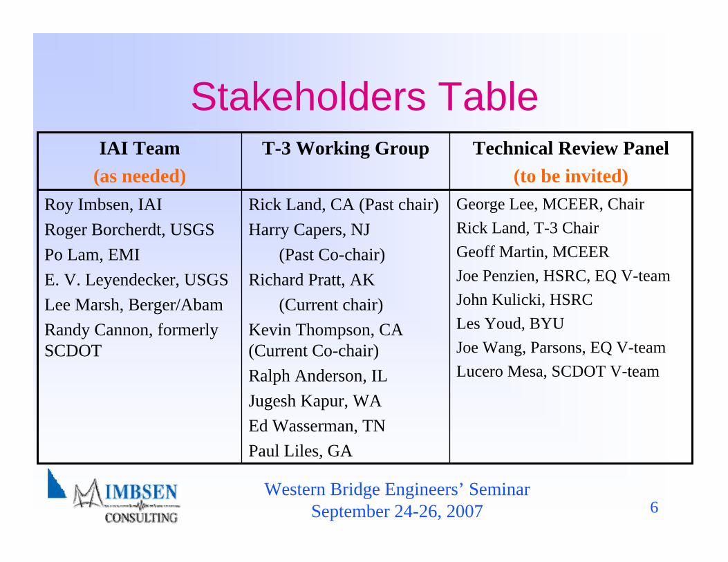
Stakeholders Table
George Lee, MCEER, ChairRick Land, T-3 ChairGeoff Martin, MCEERJoe Penzien, HSRC, EQ V-teamJohn Kulicki, HSRCLes Youd, BYUJoe Wang, Parsons, EQ V-teamLucero Mesa, SCDOT V-team
Rick Land, CA (Past chair)Harry Capers, NJ
(Past Co-chair)Richard Pratt, AK
(Current chair)Kevin Thompson, CA (Current Co-chair)Ralph Anderson, ILJugesh Kapur, WAEd Wasserman, TNPaul Liles, GA
Roy Imbsen, IAIRoger Borcherdt, USGSPo Lam, EMIE. V. Leyendecker, USGS Lee Marsh, Berger/AbamRandy Cannon, formerly SCDOT
Technical Review Panel(to be invited)
T-3 Working GroupIAI Team(as needed)
Western Bridge Engineers’ SeminarSeptember 24-26, 2007 7
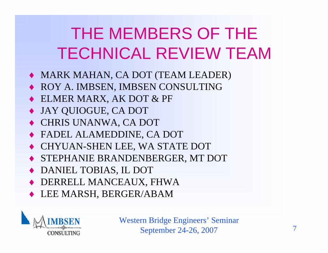
THE MEMBERS OF THE TECHNICAL REVIEW TEAM
♦ MARK MAHAN, CA DOT (TEAM LEADER)♦ ROY A. IMBSEN, IMBSEN CONSULTING♦ ELMER MARX, AK DOT & PF♦ JAY QUIOGUE, CA DOT♦ CHRIS UNANWA, CA DOT♦ FADEL ALAMEDDINE, CA DOT♦ CHYUAN-SHEN LEE, WA STATE DOT♦ STEPHANIE BRANDENBERGER, MT DOT♦ DANIEL TOBIAS, IL DOT♦ DERRELL MANCEAUX, FHWA♦ LEE MARSH, BERGER/ABAM
Western Bridge Engineers’ SeminarSeptember 24-26, 2007 8
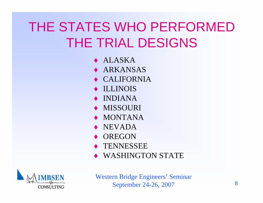
THE STATES WHO PERFORMED THE TRIAL DESIGNS
♦ ALASKA♦ ARKANSAS♦ CALIFORNIA♦ ILLINOIS♦ INDIANA♦ MISSOURI♦ MONTANA♦ NEVADA♦ OREGON♦ TENNESSEE♦ WASHINGTON STATE
Western Bridge Engineers’ SeminarSeptember 24-26, 2007 9
Support
♦MCEER/FHWA “Seismic Vulnerability of the Highway System” Task F3-4 AASHTO T-3 Support
♦NCHRP 20-07/Task 193 Updating “Recommended LRFD Guidelines for Seismic Design of Highway Bridges”
♦AASHTO T-3 Committee
Western Bridge Engineers’ SeminarSeptember 24-26, 2007 10
Background-NCHRP 20-07 Task 6 Report (1.1)
♦ Review Reference Documents♦ Finalize Seismic Hazard Level♦ Expand the Extent of the No-Analysis Zone♦ Select the Most Appropriate Design Procedure for
Steel Bridges♦ Recommend Liquefaction Design Procedure♦ Letter Reports for Tasks 1-5 (Ref. NCHRP 20-07/Task
193 Task 6 Report for Updating “Recommended LRFD Guidelines for Seismic Design of Highway Bridges” Imbsen & Associates, Inc., of TRC )
Western Bridge Engineers’ SeminarSeptember 24-26, 2007 11
Western Bridge Engineers’ SeminarSeptember 24-26, 2007 12
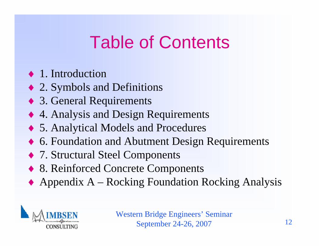
Table of Contents♦ 1. Introduction♦ 2. Symbols and Definitions♦ 3. General Requirements♦ 4. Analysis and Design Requirements♦ 5. Analytical Models and Procedures♦ 6. Foundation and Abutment Design Requirements♦ 7. Structural Steel Components♦ 8. Reinforced Concrete Components♦ Appendix A – Rocking Foundation Rocking Analysis
Western Bridge Engineers’ SeminarSeptember 24-26, 2007 13
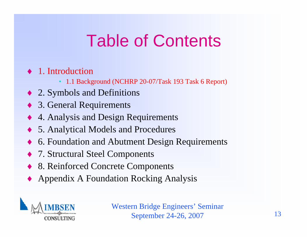
Table of Contents♦ 1. Introduction
• 1.1 Background (NCHRP 20-07/Task 193 Task 6 Report)
♦ 2. Symbols and Definitions♦ 3. General Requirements♦ 4. Analysis and Design Requirements♦ 5. Analytical Models and Procedures♦ 6. Foundation and Abutment Design Requirements♦ 7. Structural Steel Components♦ 8. Reinforced Concrete Components♦ Appendix A Foundation Rocking Analysis
Western Bridge Engineers’ SeminarSeptember 24-26, 2007 14
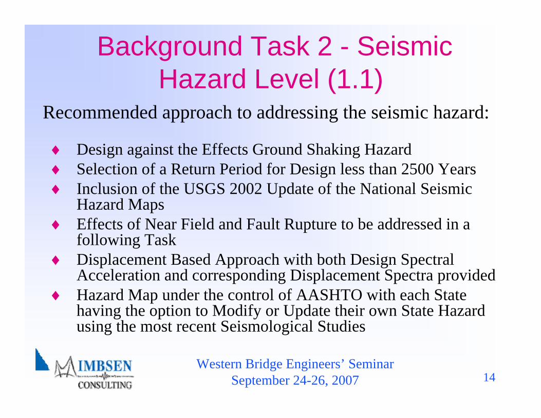
Background Task 2 - Seismic Hazard Level (1.1)
♦ Design against the Effects Ground Shaking Hazard♦ Selection of a Return Period for Design less than 2500 Years♦ Inclusion of the USGS 2002 Update of the National Seismic
Hazard Maps♦ Effects of Near Field and Fault Rupture to be addressed in a
following Task♦ Displacement Based Approach with both Design Spectral
Acceleration and corresponding Displacement Spectra provided♦ Hazard Map under the control of AASHTO with each State
having the option to Modify or Update their own State Hazard using the most recent Seismological Studies
Recommended approach to addressing the seismic hazard:
Western Bridge Engineers’ SeminarSeptember 24-26, 2007 15
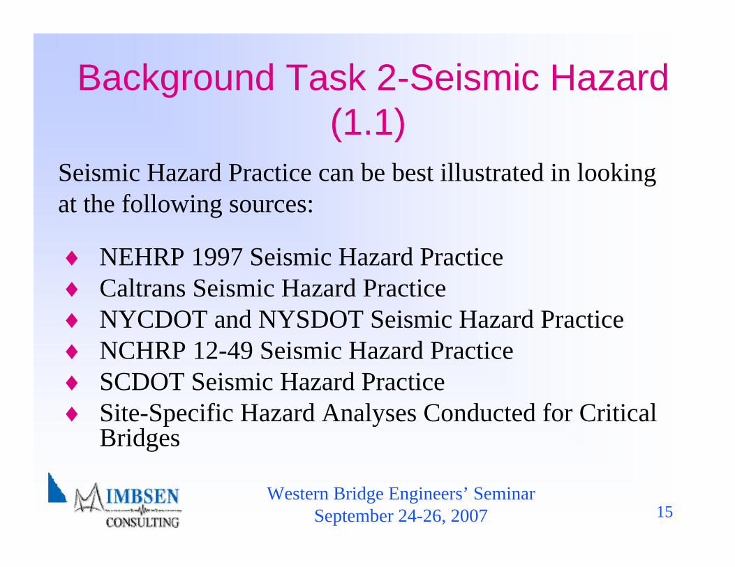
Background Task 2-Seismic Hazard (1.1)
♦ NEHRP 1997 Seismic Hazard Practice♦ Caltrans Seismic Hazard Practice♦ NYCDOT and NYSDOT Seismic Hazard Practice♦ NCHRP 12-49 Seismic Hazard Practice♦ SCDOT Seismic Hazard Practice♦ Site-Specific Hazard Analyses Conducted for Critical
Bridges
Seismic Hazard Practice can be best illustrated in looking at the following sources:

Western Bridge Engineers’ SeminarSeptember 24-26, 2007 16
Background Seismic Hazard for Normal Bridges (1.1)
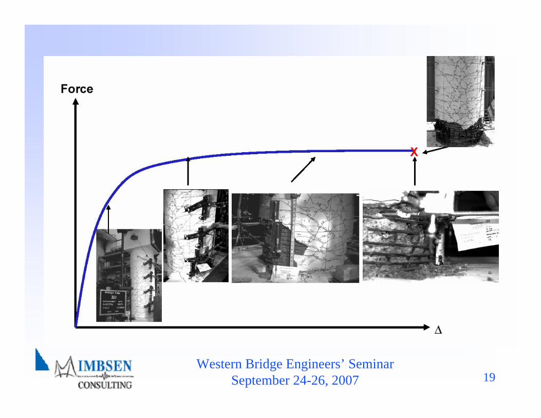
♦ Selection of a lower return period for Design is made such that Collapse Prevention is not compromised when considering large historical earthquakes.
♦ A reduction can be achieved by taking advantage of sources of conservatism not explicitly taken into account in current design procedures.
♦ The sources of conservatism are becoming more obvious based on recent findings from both observations of earthquake damage and experimental data.
Western Bridge Engineers’ SeminarSeptember 24-26, 2007 17
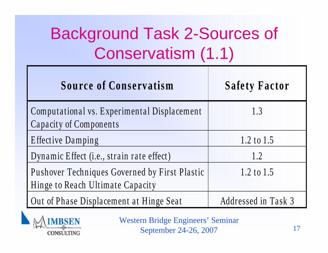
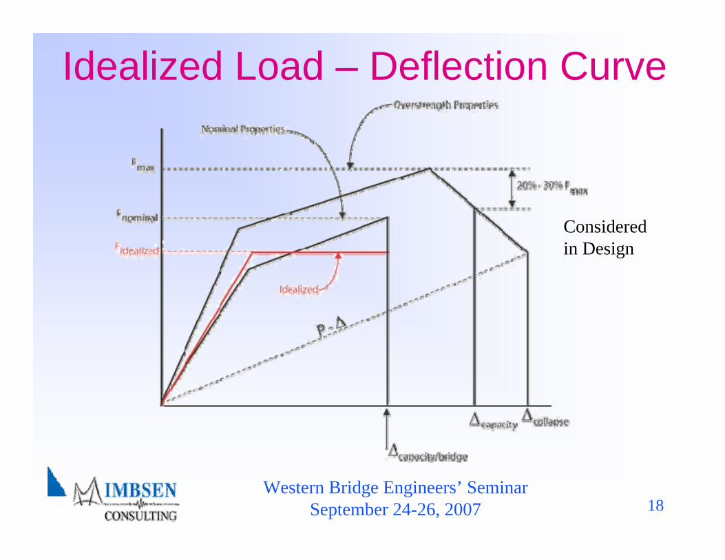
Background Task 2-Sources of Conservatism (1.1)
Sou rce of Conservatism Safe ty Factor
Computa t iona l vs. Exper imenta l Displacement Capacity of Components
1.3
Effect ive Damping 1.2 to 1.5 Dynamic Effect (i.e., st ra in ra te effect ) 1.2 Pushover Techniques Governed by F irst Plast ic Hinge to Reach Ult imate Capacity
1.2 to 1.5
Out of Phase Displacement a t Hinge Sea t Addressed in Task 3
Western Bridge Engineers’ SeminarSeptember 24-26, 2007 18
Idealized Load – Deflection Curve
Considered in Design
Western Bridge Engineers’ SeminarSeptember 24-26, 2007 19
Western Bridge Engineers’ SeminarSeptember 24-26, 2007 20
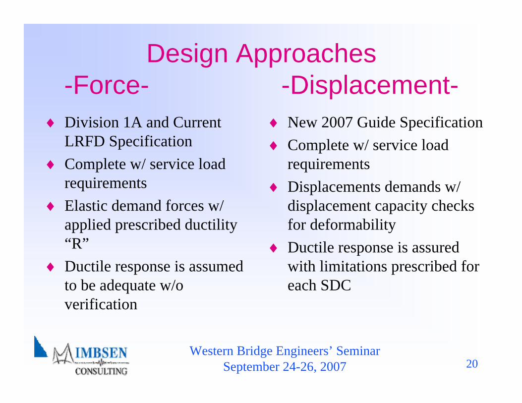
Design Approaches-Force- -Displacement-
♦ Division 1A and Current LRFD Specification
♦ Complete w/ service load requirements
♦ Elastic demand forces w/ applied prescribed ductility “R”
♦ Ductile response is assumed to be adequate w/o verification
♦ New 2007 Guide Specification♦ Complete w/ service load
requirements♦ Displacements demands w/
displacement capacity checks for deformability
♦ Ductile response is assured with limitations prescribed for each SDC
Western Bridge Engineers’ SeminarSeptember 24-26, 2007 21
Background Seismic Hazard Normal Bridges (1.1)
♦ An appropriate method to design adequate seat width(s) considering out of phase motion.
♦ An appropriate method to design the ductile substructure components without undue conservatism
Two distinctly different aspects of the design process need to be provided:
These two aspects are embedded with different levels of conservatism that need to be calibrated against the single level of hazard considered in the design process.

Western Bridge Engineers’ SeminarSeptember 24-26, 2007 22
Background Task 3 Expand the No-Analysis Zone (1.1)
P −Δ
♦ At a minimum, maintain the number of bridges under the “Seismic Demand Analysis” by comparing Proposed Guidelines to AASHTO Division I-A.
♦ Develop implicit procedures that can be used reduce the number of bridges where “Seismic Capacity Analysis” needs to be performed, This objective is accomplished by identifying a threshold where an implicit procedures can be used (Drift Criteria, Column Shear Criteria).
♦ Identify threshold where “Capacity Design” shall be used. This objective is achieved in conjunction with the “Seismic Capacity Analysis” requirements.
Western Bridge Engineers’ SeminarSeptember 24-26, 2007 23
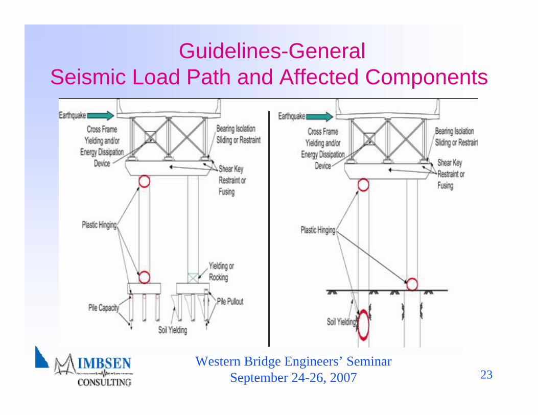
Guidelines-General Seismic Load Path and Affected Components

Western Bridge Engineers’ SeminarSeptember 24-26, 2007 24
Guidelines Performance Criteria
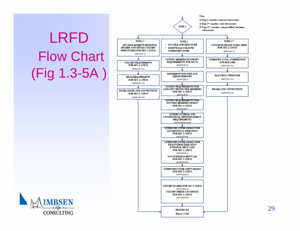
♦ Type 1 – Design a ductile substructure with an essentially elastic superstructure.
♦ Type 2 – Design an essentially elastic substructure with a ductile superstructure.
♦ Type 3 – Design an elastic superstructure and substructure with a fusing mechanism at the interface between the superstructure and the substructure.
Western Bridge Engineers’ SeminarSeptember 24-26, 2007 25
GuidelinesPerformance Criteria
♦ For Type 3 choice, the designer shall assess the overstrength capacity for the fusing interface including shear keys and bearings, then design for an essentially elastic superstructure and substructure.
♦ The minimum overstrength lateral design force shall be calculated using an acceleration of 0.4 g or the elastic seismic force whichever is smaller.
♦ If isolation devices are used, the superstructure shall be designed as essentially elastic.
Western Bridge Engineers’ SeminarSeptember 24-26, 2007 26
Table of Contents♦ 1. Introduction
– 1.3 Flow Charts♦ 2. Symbols and Definitions♦ 3. General Requirements♦ 4. Analysis and Design Requirements♦ 5. Analytical Models and Procedures♦ 6. Foundation and Abutment Design Requirements♦ 7. Structural Steel Components♦ 8. Reinforced Concrete Components♦ Appendix A – Rocking Foundation Rocking Analysis
Western Bridge Engineers’ SeminarSeptember 24-26, 2007 27
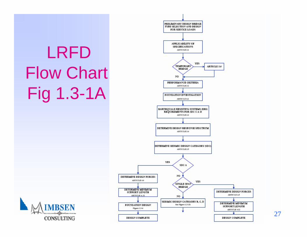
LRFD Flow Chart Fig 1.3-1A
Western Bridge Engineers’ SeminarSeptember 24-26, 2007 28
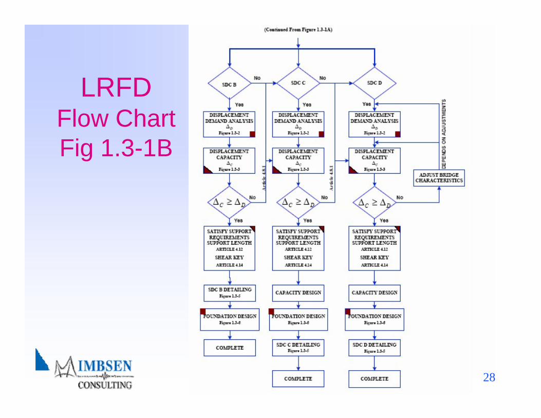
LRFD Flow Chart Fig 1.3-1B
Western Bridge Engineers’ SeminarSeptember 24-26, 2007 29
LRFDFlow Chart
(Fig 1.3-5A )
Western Bridge Engineers’ SeminarSeptember 24-26, 2007 30
Western Bridge Engineers’ SeminarSeptember 24-26, 2007 31
Table of Contents♦ 1. Introduction♦ 2. Symbols and Definitions♦ 3. General Requirements♦ 4. Analysis and Design Requirements♦ 5. Analytical Models and Procedures♦ 6. Foundation and Abutment Design Requirements♦ 7. Structural Steel Components♦ 8. Reinforced Concrete Components♦ Appendix A – Rocking Foundation Rocking Analysis

Western Bridge Engineers’ SeminarSeptember 24-26, 2007 32
Applicability (3.1)
♦Design and Construction of New Bridges♦Bridges having Superstructures Consisting of:
– Slab– Beam– Girder– Box Girder
♦Spans less than 500 feet

Western Bridge Engineers’ SeminarSeptember 24-26, 2007 33
Performance Criteria (3.2)
♦One design level for life safety♦Seismic hazard level for 7% probability of
exceedance in 75 years (i.e.,1000 year return period)
♦Low probability of collapse♦May have significant damage and disruption to
service
Western Bridge Engineers’ SeminarSeptember 24-26, 2007 34
Table of Contents♦ 1. Introduction♦ 2. Symbols and Definitions♦ 3. General Requirements
3.3 Earthquake Resisting Systems♦ 4. Analysis and Design Requirements♦ 5. Analytical Models and Procedures♦ 6. Foundation and Abutment Design Requirements♦ 7. Structural Steel Components♦ 8. Reinforced Concrete Components♦ Appendix A – Rocking Foundation Rocking Analysis
Western Bridge Engineers’ SeminarSeptember 24-26, 2007 35
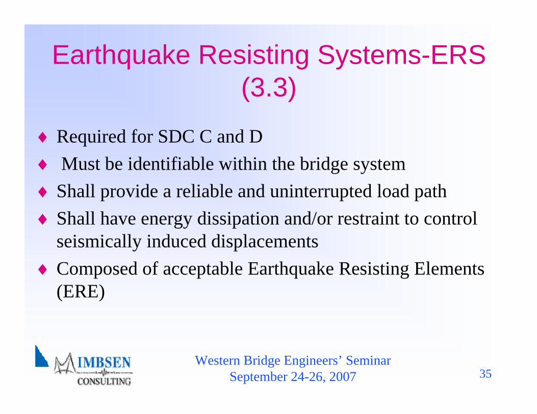
Earthquake Resisting Systems-ERS (3.3)
♦ Required for SDC C and D♦ Must be identifiable within the bridge system♦ Shall provide a reliable and uninterrupted load path♦ Shall have energy dissipation and/or restraint to control
seismically induced displacements♦ Composed of acceptable Earthquake Resisting Elements
(ERE)
Western Bridge Engineers’ SeminarSeptember 24-26, 2007 36
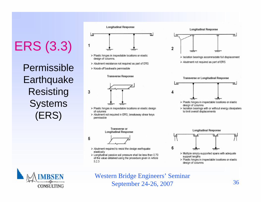
Permissible Earthquake Resisting Systems (ERS)
ERS (3.3)

Western Bridge Engineers’ SeminarSeptember 24-26, 2007 37
Permissible Earthquake Resisting
Elements that Require Owner’s
Approval
ERS (3.3)
Western Bridge Engineers’ SeminarSeptember 24-26, 2007 38
Table of Contents♦ 1. Introduction♦ 2. Symbols and Definitions♦ 3. General Requirements
Seismic Ground Shaking Hazard♦ 4. Analysis and Design Requirements♦ 5. Analytical Models and Procedures♦ 6. Foundation and Abutment Design Requirements♦ 7. Structural Steel Components♦ 8. Reinforced Concrete Components♦ Appendix A – Rocking Foundation Rocking Analysis
Western Bridge Engineers’ SeminarSeptember 24-26, 2007 39
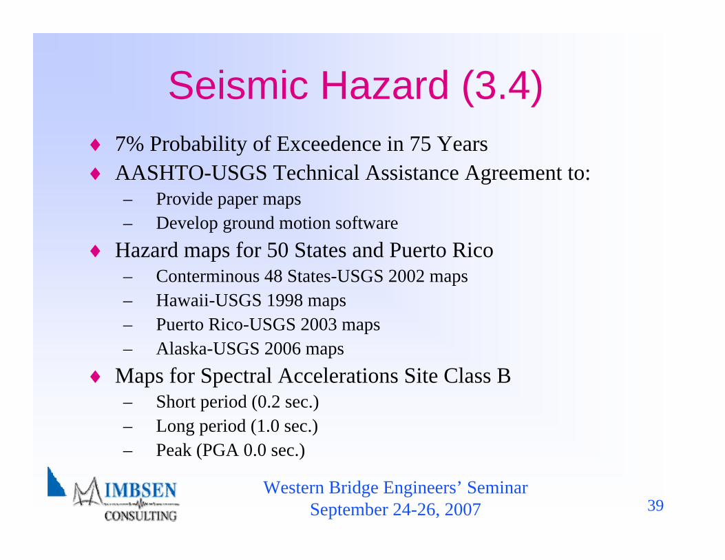
Seismic Hazard (3.4) ♦ 7% Probability of Exceedence in 75 Years ♦ AASHTO-USGS Technical Assistance Agreement to:
– Provide paper maps– Develop ground motion software
♦ Hazard maps for 50 States and Puerto Rico– Conterminous 48 States-USGS 2002 maps– Hawaii-USGS 1998 maps– Puerto Rico-USGS 2003 maps– Alaska-USGS 2006 maps
♦ Maps for Spectral Accelerations Site Class B– Short period (0.2 sec.)– Long period (1.0 sec.)– Peak (PGA 0.0 sec.)

Western Bridge Engineers’ SeminarSeptember 24-26, 2007 40
Design Spectrum,
Figure 3.4.1-1
Seismic Hazard 2-Point Method
for Design Spectrum
Construction (3.4)
Western Bridge Engineers’ SeminarSeptember 24-26, 2007 41
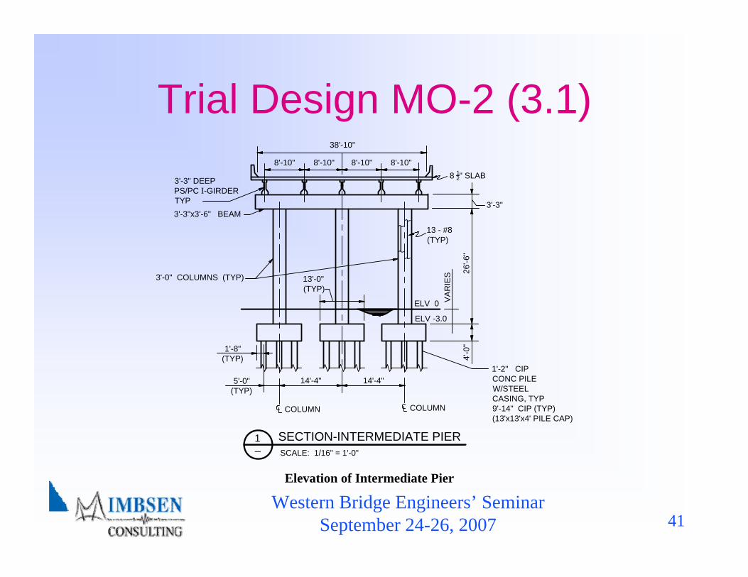
Trial Design MO-2 (3.1)38'-10"
8'-10" 8'-10" 8'-10" 8'-10"
3'-3" DEEPPS/PC I-GIRDERTYP3'-3"x3'-6" BEAM
3'-0" COLUMNS (TYP) 13'-0" (TYP)
8 12" SLAB
3'-3"
26'-6
"4'
-0"
VA
RIE
S
ELV -3.0
13 - #8(TYP)
1'-8"(TYP)
5'-0"(TYP)
COLUMN
1'-2" CIPCONC PILEW/STEELCASING, TYP9'-14" CIP (TYP)(13'x13'x4' PILE CAP)
SECTION-INTERMEDIATE PIER1_
SCALE: 1/16" = 1'-0"
Elevation of Intermediate Pier
14'-4" 14'-4"
ELV 0
COLUMN
Western Bridge Engineers’ SeminarSeptember 24-26, 2007 42
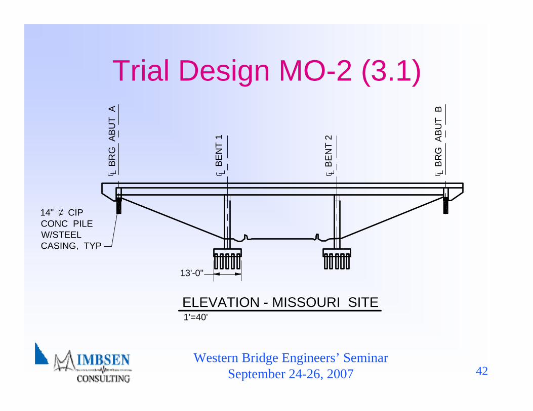
Trial Design MO-2 (3.1)B
RG
AB
UT
A
BE
NT
1
BE
NT
2
BR
G A
BU
T B
14" CIPCONC PILEW/STEELCASING, TYP
13'-0"
ELEVATION - MISSOURI SITE1'=40'

Western Bridge Engineers’ SeminarSeptember 24-26, 2007 43
Figure 3.4.1-2a Peak Horizontal Ground Acceleration for the Conterminous United States (Western) With 7 Percent Probability of Exceedance in 75 Years (Approx. 1000 Year Return Period).
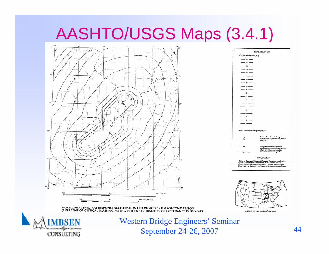
AASHTO/USGS Maps
(3.4.1)
Western Bridge Engineers’ SeminarSeptember 24-26, 2007 44
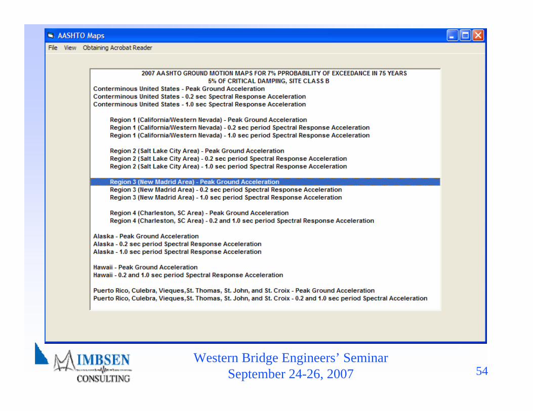
AASHTO/USGS Maps (3.4.1)
Western Bridge Engineers’ SeminarSeptember 24-26, 2007 45
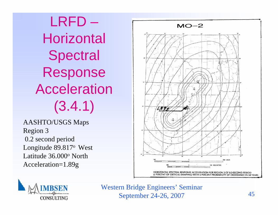
LRFD –Horizontal Spectral
Response Acceleration
(3.4.1)AASHTO/USGS Maps Region 30.2 second periodLongitude 89.817o WestLatitude 36.000o NorthAcceleration=1.89g
Western Bridge Engineers’ SeminarSeptember 24-26, 2007 46
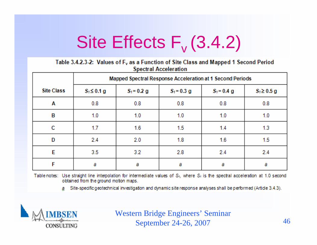
Site Effects Fv (3.4.2)
Western Bridge Engineers’ SeminarSeptember 24-26, 2007 47
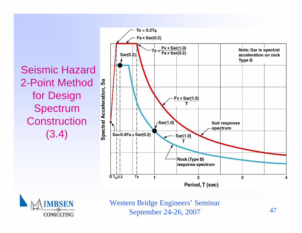
Seismic Hazard 2-Point Method
for Design Spectrum
Construction (3.4)
Western Bridge Engineers’ SeminarSeptember 24-26, 2007 48
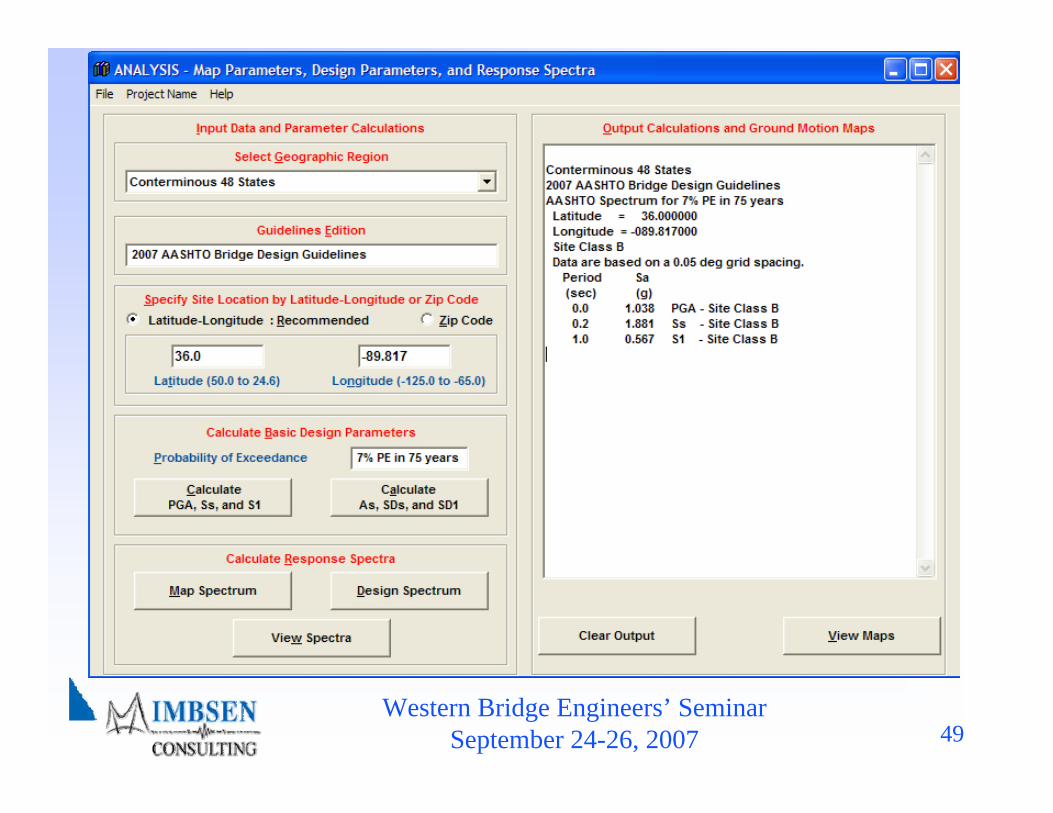
Western Bridge Engineers’ SeminarSeptember 24-26, 2007 49
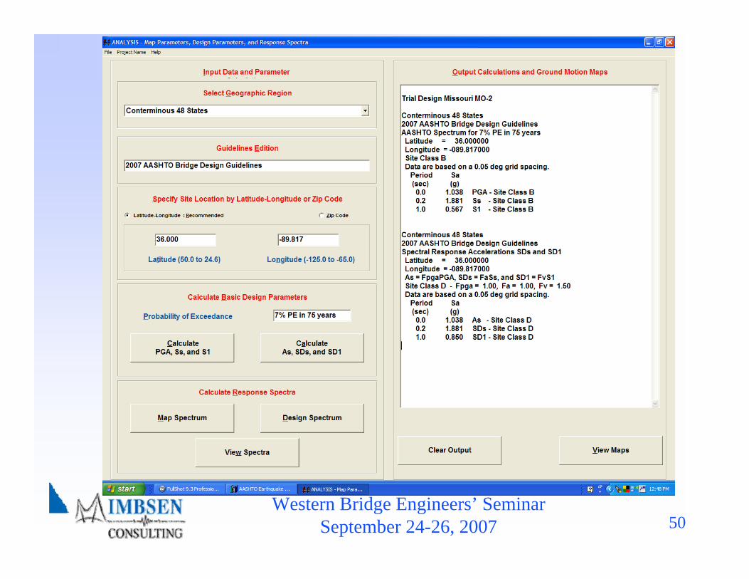
Western Bridge Engineers’ SeminarSeptember 24-26, 2007 50
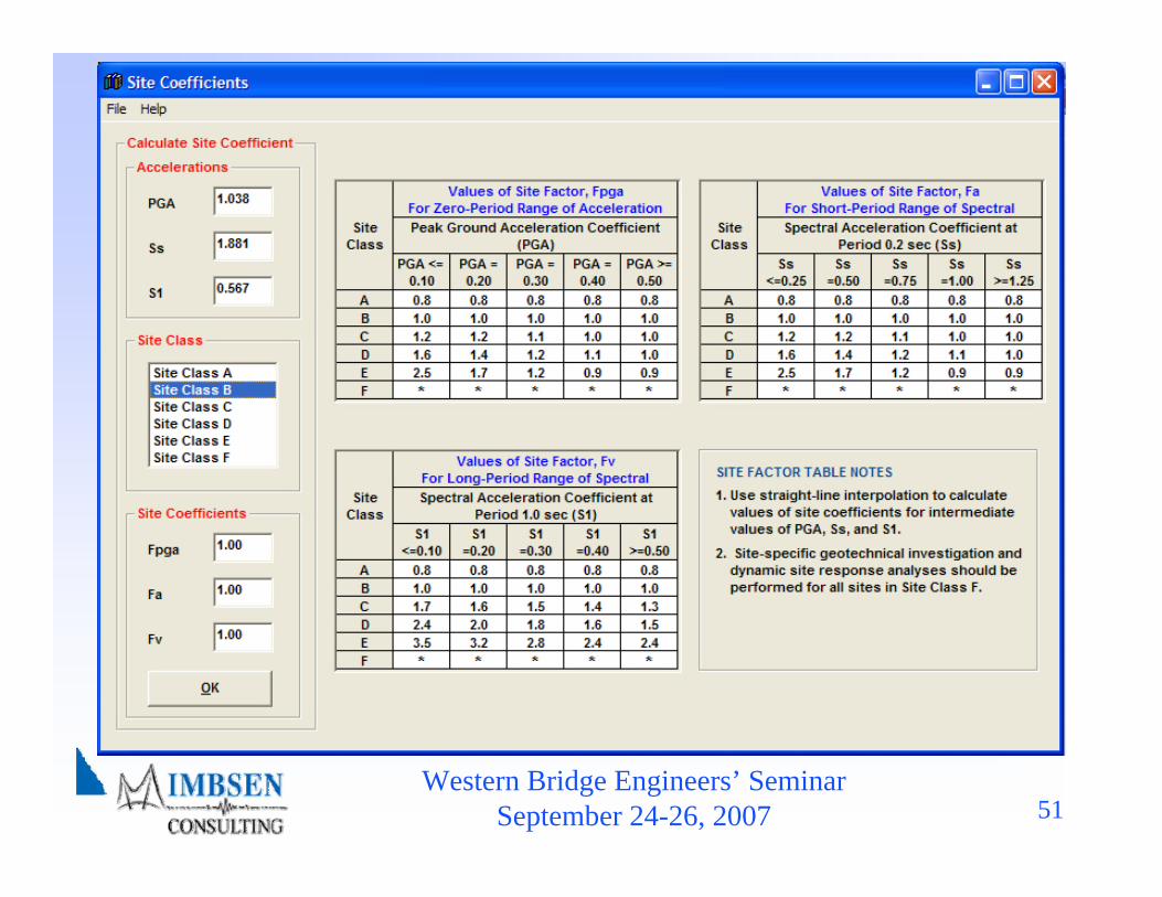
Western Bridge Engineers’ SeminarSeptember 24-26, 2007 51

Western Bridge Engineers’ SeminarSeptember 24-26, 2007 52
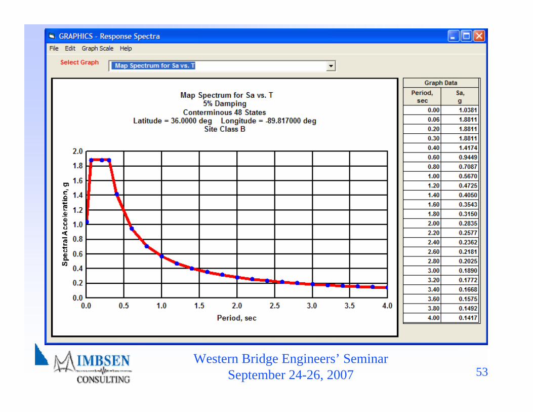
Western Bridge Engineers’ SeminarSeptember 24-26, 2007 53
Western Bridge Engineers’ SeminarSeptember 24-26, 2007 54

Western Bridge Engineers’ SeminarSeptember 24-26, 2007 55

Western Bridge Engineers’ SeminarSeptember 24-26, 2007 56
Table of Contents♦ 1. Introduction♦ 2. Symbols and Definitions♦ 3. General Requirements
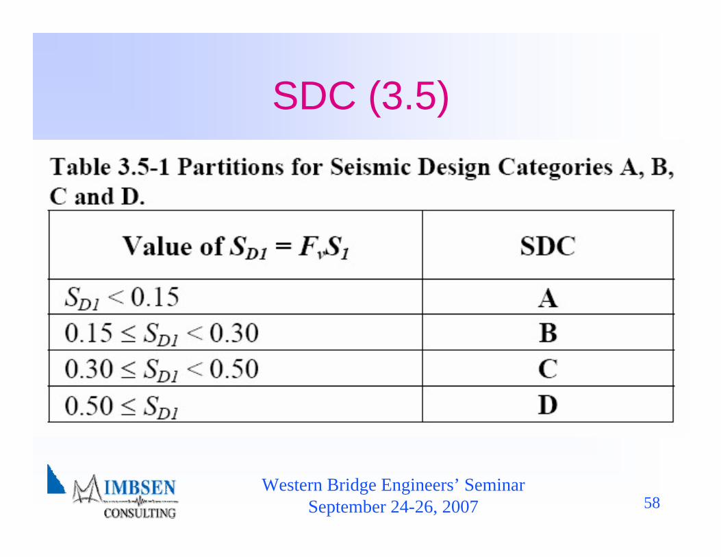
3.5 Seismic Design Category♦ 4. Analysis and Design Requirements♦ 5. Analytical Models and Procedures♦ 6. Foundation and Abutment Design Requirements♦ 7. Structural Steel Components♦ 8. Reinforced Concrete Components♦ Appendix A – Rocking Foundation Rocking Analysis

Western Bridge Engineers’ SeminarSeptember 24-26, 2007 57
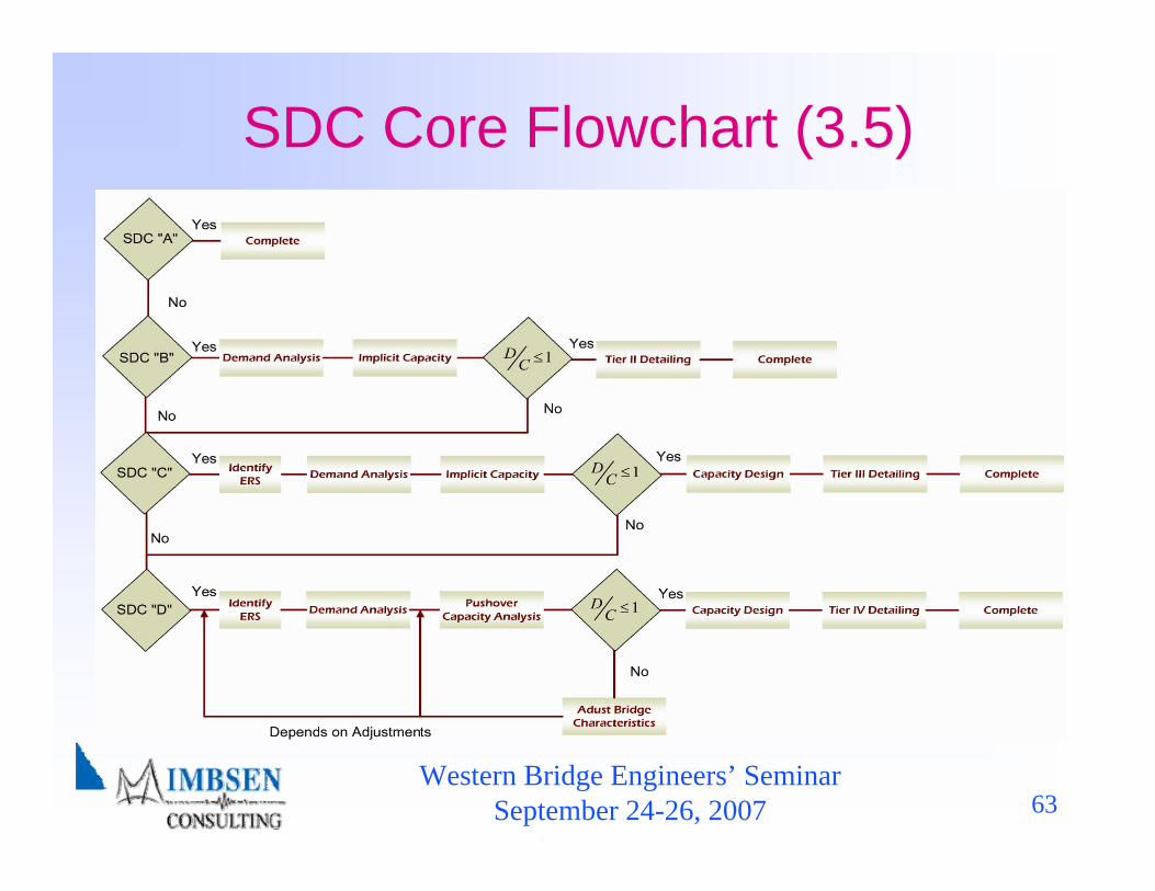
SDC Range of Applicable Analysis (3.5)
♦ Seismic Demand Analysis requirement♦ Seismic Capacity Analysis requirement♦ Capacity Design requirement♦ Level of seismic detailing requirement including four
tiers corresponding to SDC A, B, C and D♦ Earthquake Resistant System
Four Seismic Design Categories (SDC) A, B, C and D encompassing requirements for:
Western Bridge Engineers’ SeminarSeptember 24-26, 2007 58
SDC (3.5)

Western Bridge Engineers’ SeminarSeptember 24-26, 2007 59
SDC A (3.5)
Western Bridge Engineers’ SeminarSeptember 24-26, 2007 60
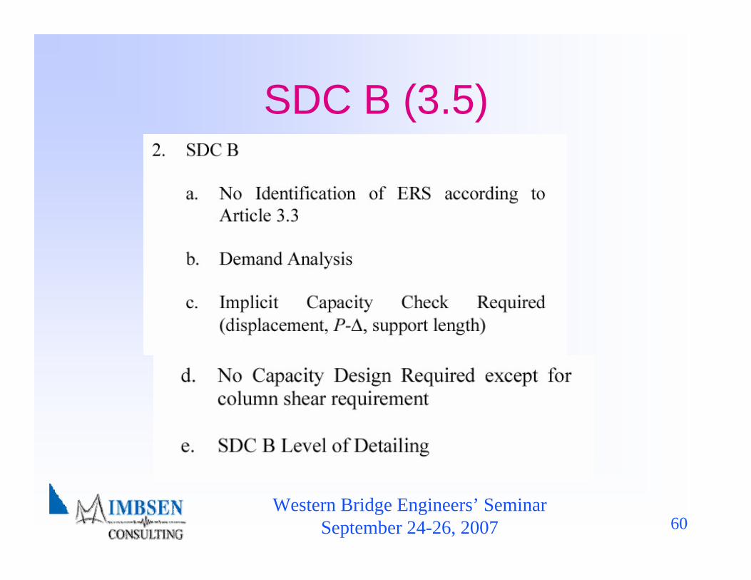
SDC B (3.5)

Western Bridge Engineers’ SeminarSeptember 24-26, 2007 61
SDC C (3.5)
Western Bridge Engineers’ SeminarSeptember 24-26, 2007 62
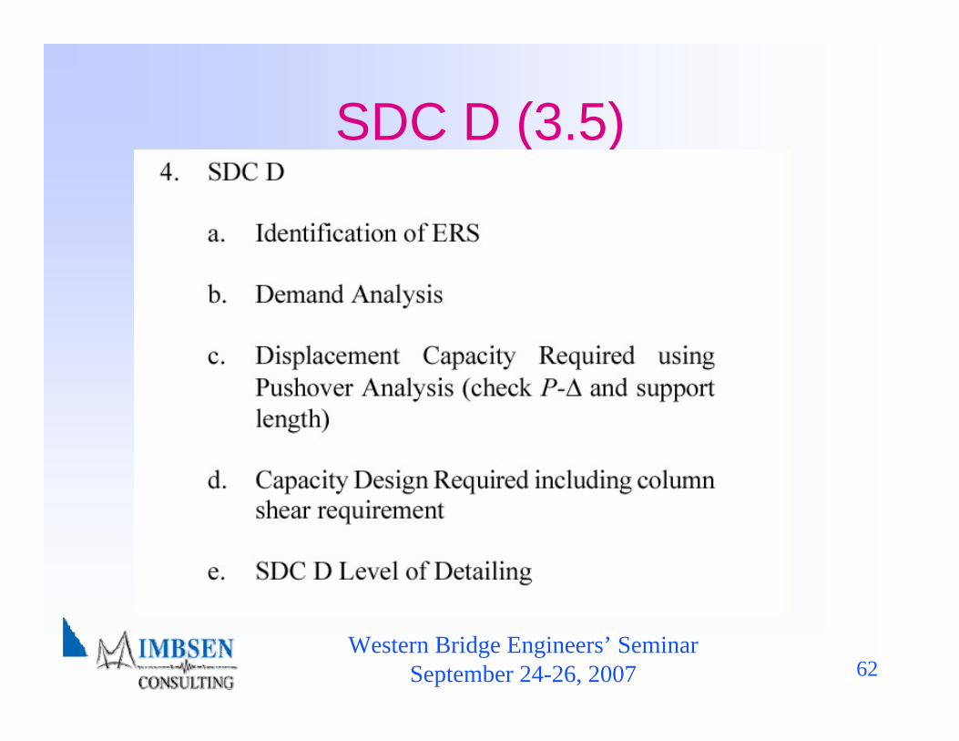
SDC D (3.5)
Western Bridge Engineers’ SeminarSeptember 24-26, 2007 63
SDC Core Flowchart (3.5)

Western Bridge Engineers’ SeminarSeptember 24-26, 2007 64
Table of Contents♦ 1. Introduction♦ 2. Symbols and Definitions♦ 3. General Requirements♦ 4. Analysis and Design Requirements♦ 5. Analytical Models and Procedures♦ 6. Foundation and Abutment Design Requirements♦ 7. Structural Steel Components♦ 8. Reinforced Concrete Components♦ Appendix A – Rocking Foundation Rocking Analysis

Western Bridge Engineers’ SeminarSeptember 24-26, 2007 65
Balanced Stiffness
Recommendation (4.1)
Western Bridge Engineers’ SeminarSeptember 24-26, 2007 66
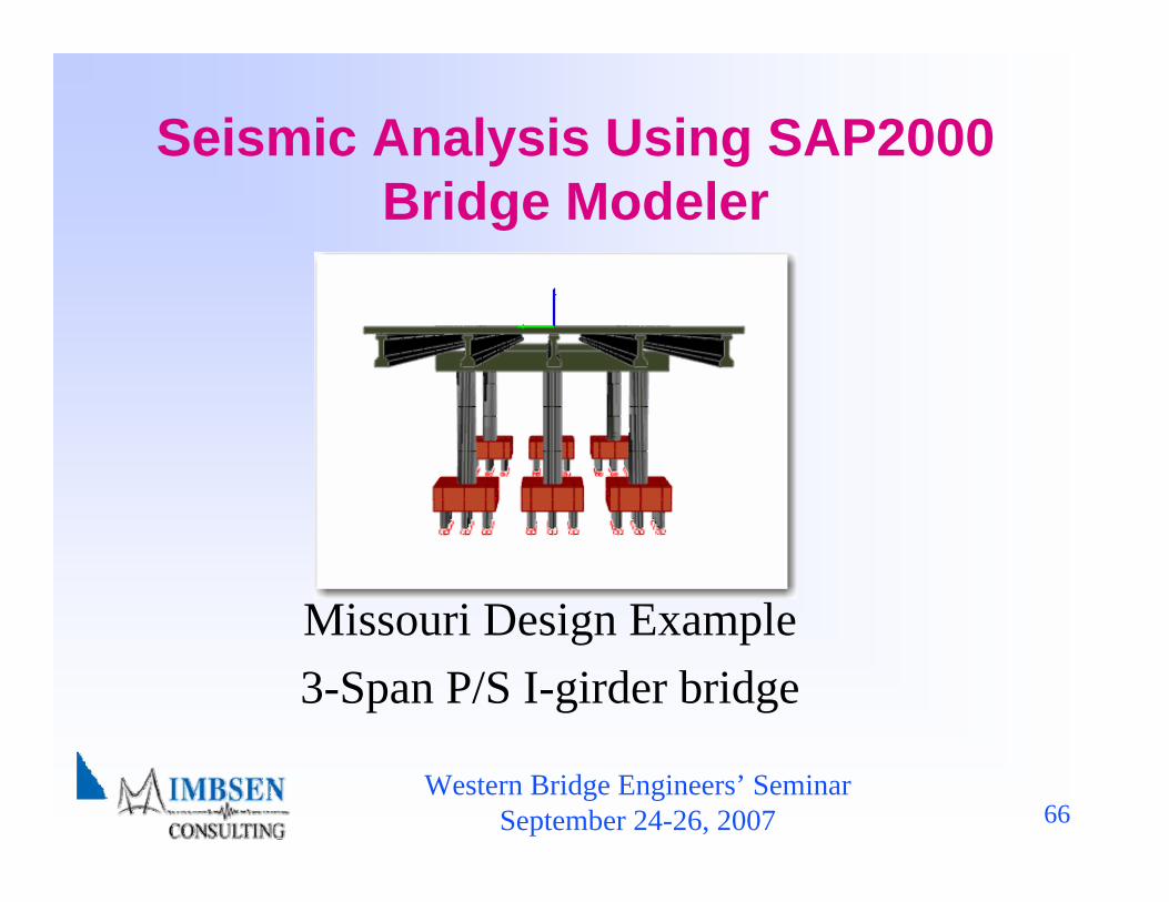
Seismic Analysis Using SAP2000 Bridge Modeler
Missouri Design Example 3-Span P/S I-girder bridge
Western Bridge Engineers’ SeminarSeptember 24-26, 2007 67
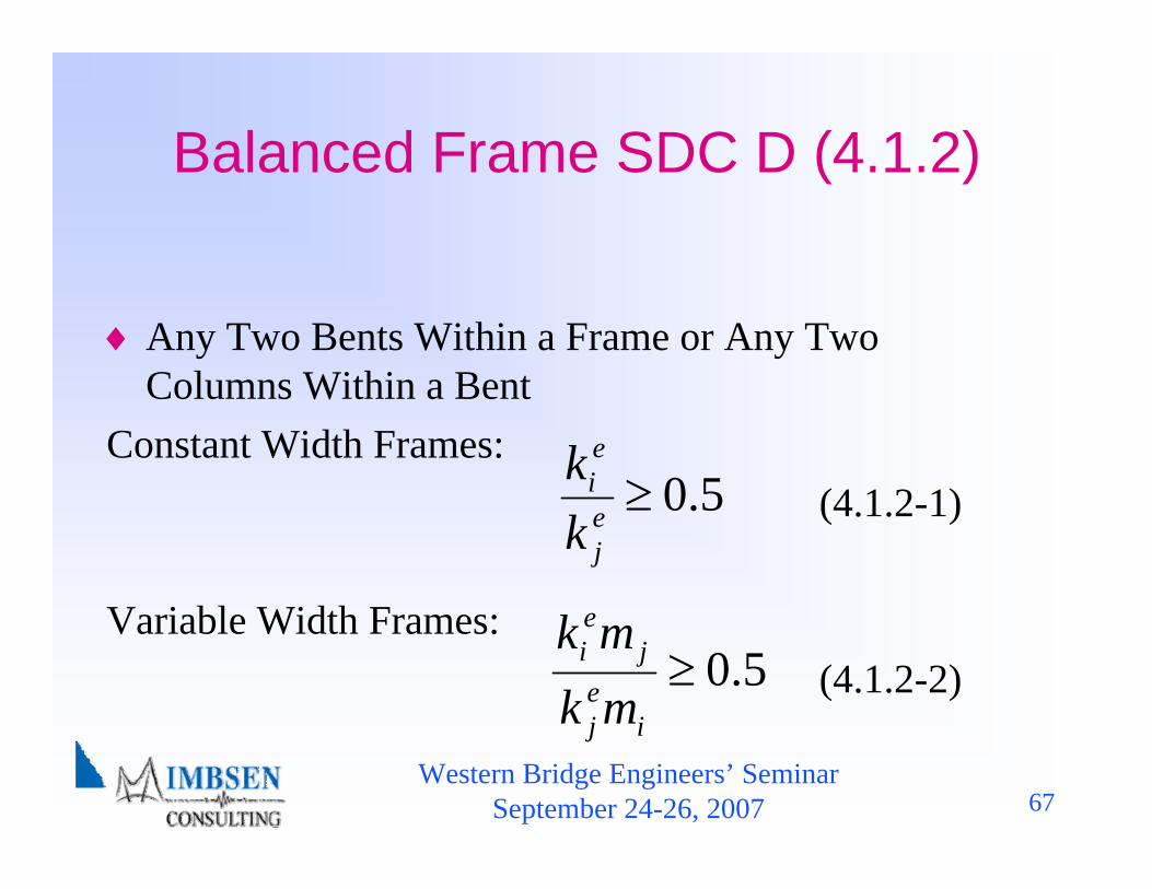
Balanced Frame SDC D (4.1.2)
♦ Any Two Bents Within a Frame or Any Two Columns Within a Bent
Constant Width Frames:(4.1.2-1)
Variable Width Frames:(4.1.2-2)
5.0≥ej
ei
kk
5.0≥i
ej
jei
mkmk
Western Bridge Engineers’ SeminarSeptember 24-26, 2007 68
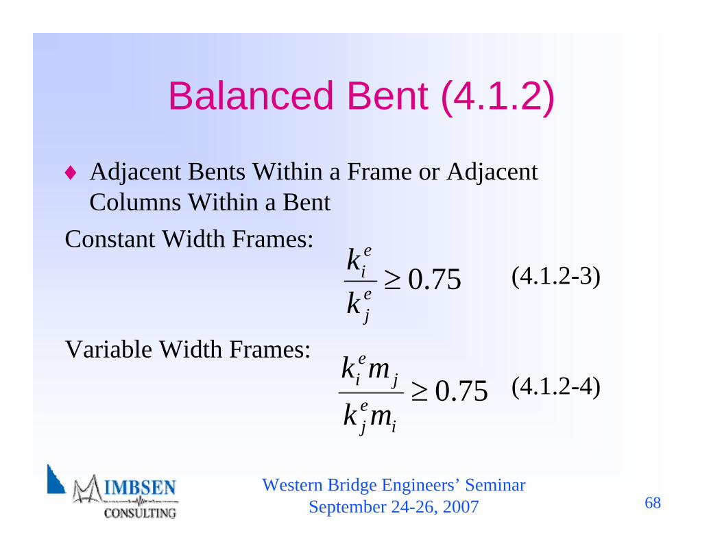
Balanced Bent (4.1.2)
♦ Adjacent Bents Within a Frame or Adjacent Columns Within a Bent
Constant Width Frames:(4.1.2-3)
Variable Width Frames:(4.1.2-4)
75.0≥ej
ei
kk
75.0≥i
ej
jei
mkmk
Western Bridge Engineers’ SeminarSeptember 24-26, 2007 69
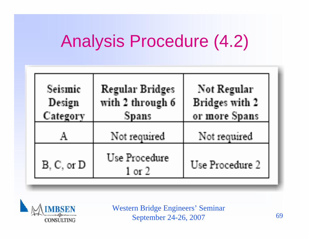
Analysis Procedure (4.2)

Western Bridge Engineers’ SeminarSeptember 24-26, 2007 70
Displacement Demands (4.3)
♦Horizontal ground motions for SDC B,C, & D determined independently along two axes and combined
♦Displacement modification for other than 5% damped bridges having energy dissipation at abutments
♦Displacement magnification for short period short period structures
Western Bridge Engineers’ SeminarSeptember 24-26, 2007 71
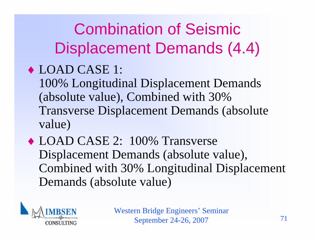
Combination of Seismic Displacement Demands (4.4)
♦LOAD CASE 1: 100% Longitudinal Displacement Demands (absolute value), Combined with 30% Transverse Displacement Demands (absolute value)
♦LOAD CASE 2: 100% Transverse Displacement Demands (absolute value), Combined with 30% Longitudinal Displacement Demands (absolute value)
Western Bridge Engineers’ SeminarSeptember 24-26, 2007 72
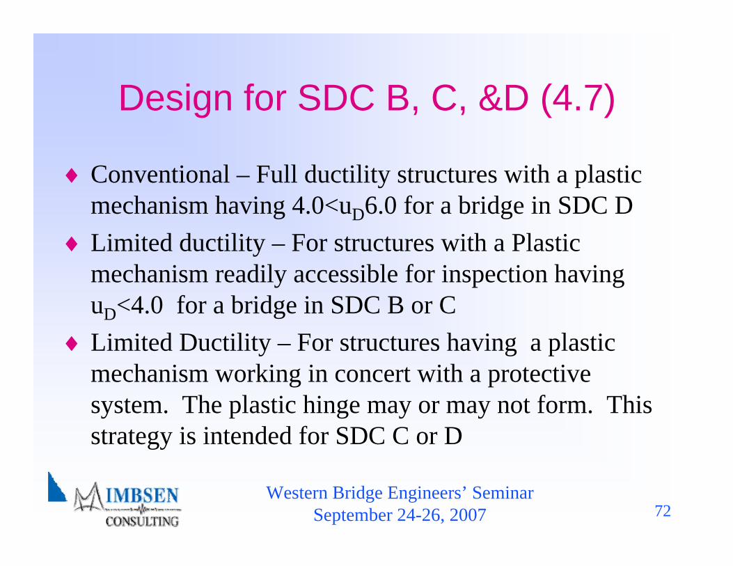
Design for SDC B, C, &D (4.7)
♦ Conventional – Full ductility structures with a plastic mechanism having 4.0<uD6.0 for a bridge in SDC D
♦ Limited ductility – For structures with a Plastic mechanism readily accessible for inspection having uD<4.0 for a bridge in SDC B or C
♦ Limited Ductility – For structures having a plastic mechanism working in concert with a protective system. The plastic hinge may or may not form. This strategy is intended for SDC C or D
Western Bridge Engineers’ SeminarSeptember 24-26, 2007 73
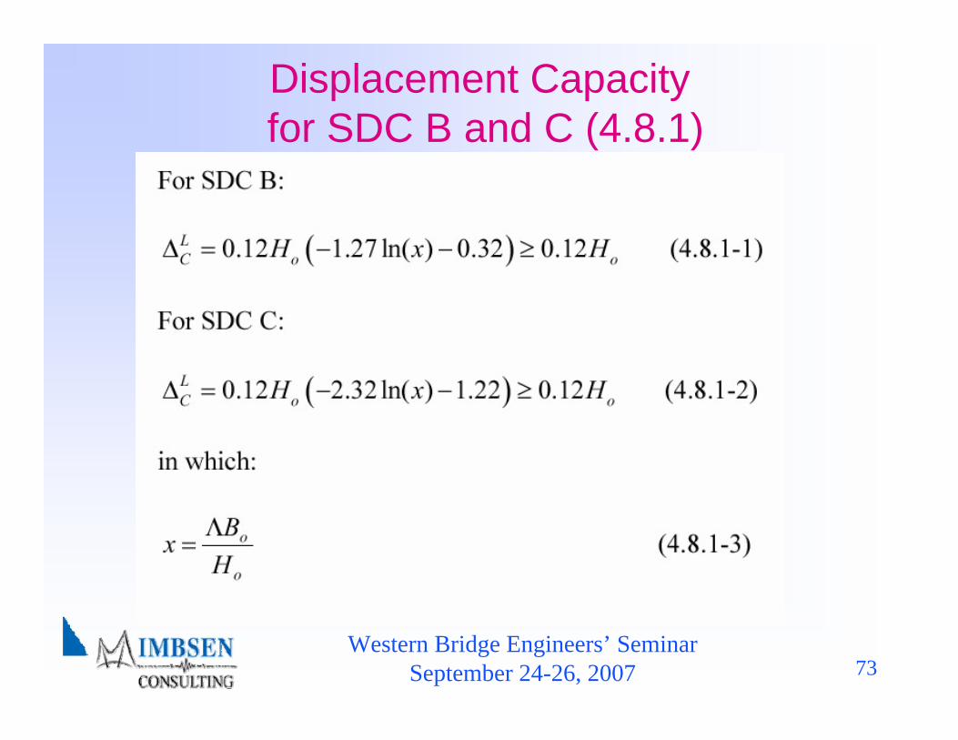
Displacement Capacityfor SDC B and C (4.8.1)

Western Bridge Engineers’ SeminarSeptember 24-26, 2007 74
Displacement Capacity for SDC D (4.8.2)
♦ Inelastic Quasi-Static Pushover analysis (IQPA) is required to determine realistic displacement capacities as it reaches it’s limit states
♦ IQPA is an incremental linear analysis which captures the overall nonlinear behavior of the structure and it’s elements through each limit state
♦ The IQPA model includes the redistribution of forces as each limit state is reached
♦ Foundation effects may also be included in the model
Western Bridge Engineers’ SeminarSeptember 24-26, 2007 75
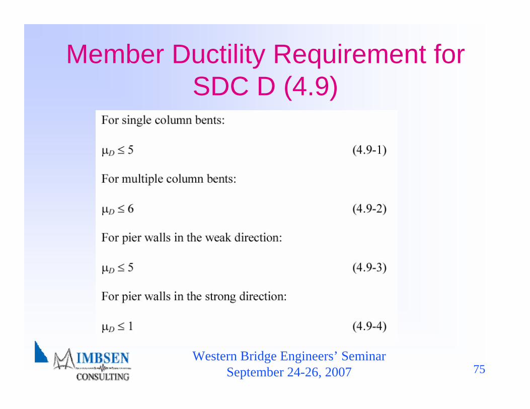
Member Ductility Requirement for SDC D (4.9)
Western Bridge Engineers’ SeminarSeptember 24-26, 2007 76
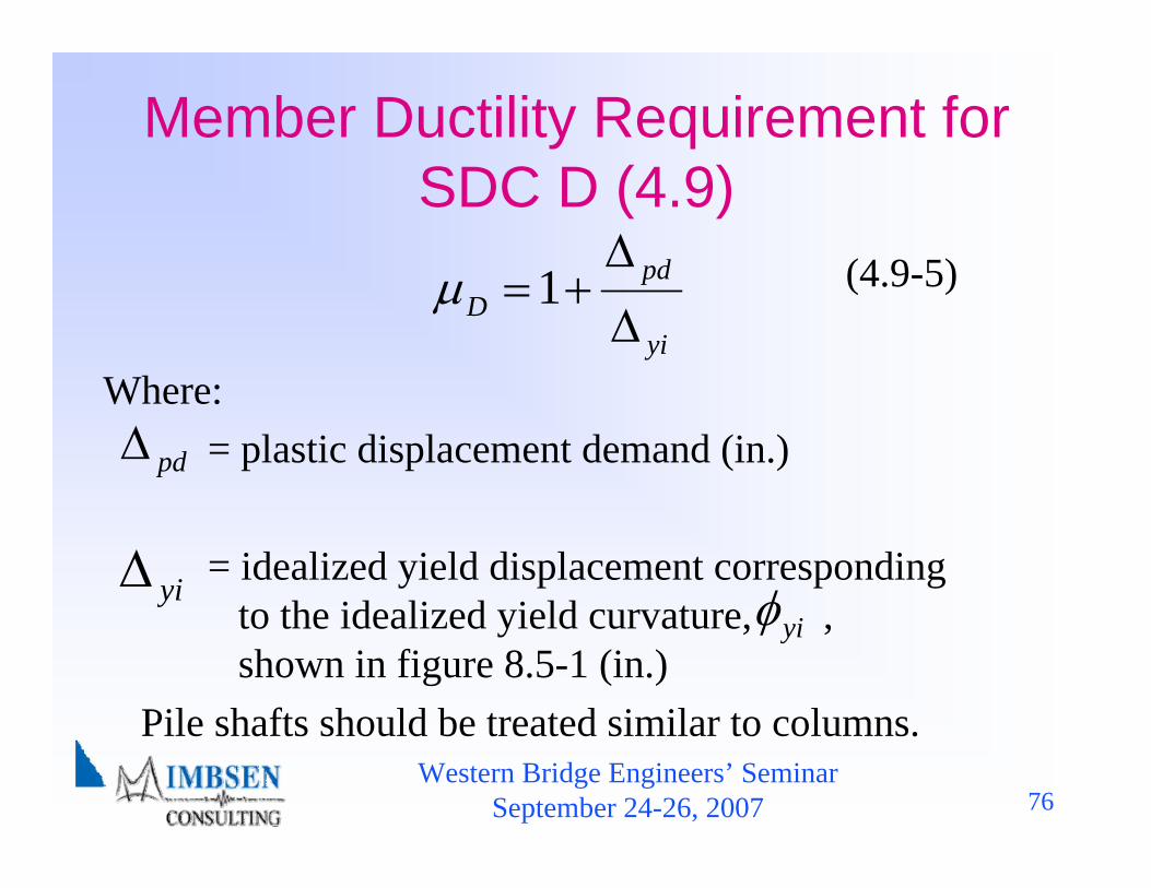
(4.9-5)
Where:= plastic displacement demand (in.)
= idealized yield displacement corresponding to the idealized yield curvature, ,shown in figure 8.5-1 (in.)
Pile shafts should be treated similar to columns.
Member Ductility Requirement for SDC D (4.9)
yiΔ
pdΔ
yi
pdD Δ
Δ+=1μ
yiφ
Western Bridge Engineers’ SeminarSeptember 24-26, 2007 77
Capacity Design Requirement for SDC C & D
♦ Capacity protection is required for all members that are not participating as part of the energy dissipating system
♦ Capacity protected members include:– Superstructures– Joints and cap beams– Spread footings– Pile caps– Foundations
Western Bridge Engineers’ SeminarSeptember 24-26, 2007 78
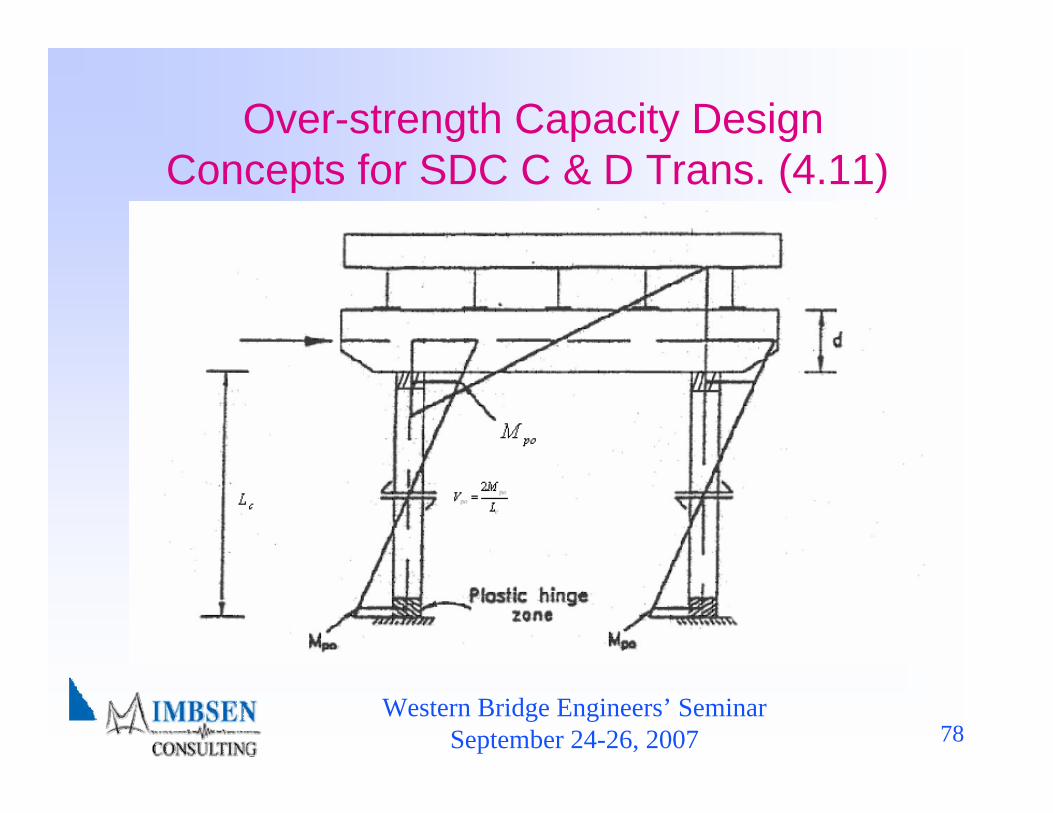
Over-strength Capacity Design Concepts for SDC C & D Trans. (4.11)
Western Bridge Engineers’ SeminarSeptember 24-26, 2007 79
Minimum Support LengthRequirements (4.12)
♦ Minimum edge distance♦ Other movement attributed to prestress shortening,
creep, shrinkage, and thermal expansion or contraction♦ Skew effect♦ Relative hinge displacement
The calculation for a hinge seat width involves four components:

Western Bridge Engineers’ SeminarSeptember 24-26, 2007 80
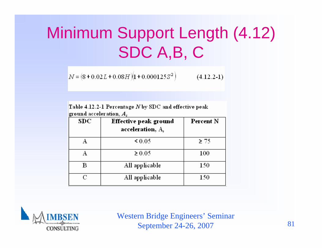
Minimum Support Length (4.12)SDC A, B, C & D
Western Bridge Engineers’ SeminarSeptember 24-26, 2007 81
Minimum Support Length (4.12)SDC A,B, C
Western Bridge Engineers’ SeminarSeptember 24-26, 2007 82
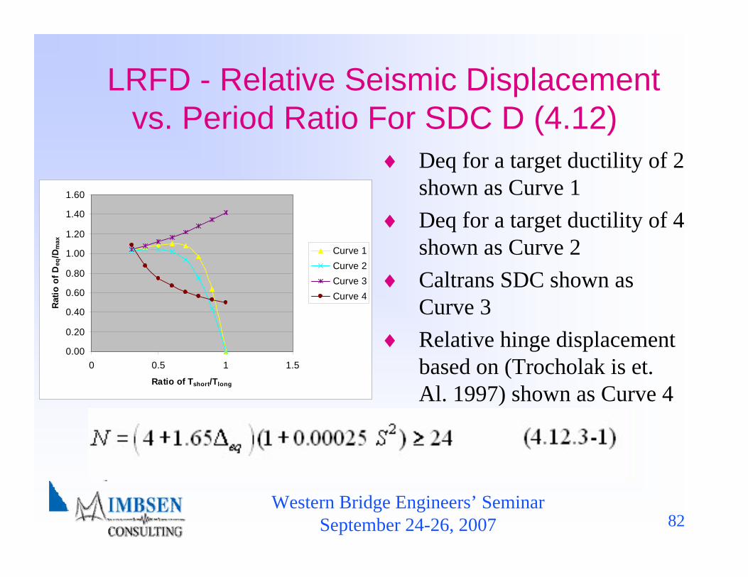
LRFD - Relative Seismic Displacement vs. Period Ratio For SDC D (4.12)
0.00
0.20
0.40
0.60
0.80
1.00
1.20
1.40
1.60
0 0.5 1 1.5
Ratio of Tshort/Tlong
Rat
io o
f Deq
/Dm
ax
Curve 1Curve 2Curve 3Curve 4
♦ Deq for a target ductility of 2 shown as Curve 1
♦ Deq for a target ductility of 4 shown as Curve 2
♦ Caltrans SDC shown as Curve 3
♦ Relative hinge displacement based on (Trocholak is et. Al. 1997) shown as Curve 4
Western Bridge Engineers’ SeminarSeptember 24-26, 2007 83
Table of Contents♦ 1. Introduction♦ 2. Symbols and Definitions♦ 3. General Requirements♦ 4. Analysis and Design Requirements♦ 5. Analytical Models and Procedures♦ 6. Foundation and Abutment Design Requirements♦ 7. Structural Steel Components♦ 8. Reinforced Concrete Components♦ Appendix A – Rocking Foundation Rocking Analysis
Western Bridge Engineers’ SeminarSeptember 24-26, 2007 84
Ductility Demand on a Column or Pier is a Function of
♦ Earthquake characteristics, including duration, frequency content and near-field (or pulse) effects.
♦ Design force level♦ Periods of vibration of the bridge♦ Shape of the inelastic hysteresis loop of the columns,
and hence effective hysteretic damping♦ Elastic damping coefficient♦ Contribution of foundation and soil conditions to
structural flexibility♦ Spread of plasticity (plastic hinge length) in the column

Western Bridge Engineers’ SeminarSeptember 24-26, 2007 85
Plastic Moment Capacity SDC B, C & D (8.5)
♦ Moment-Curvature Analyses♦ Expected Material Properties♦ Axial Dead Load Forces with Overturning♦ Curve Idealized as Elastic Perfectly Plastic♦ Elastic Portion of the Curve Pass through the point of
marking the first reinforcing bar yield♦ Plastic moment capacity determined from equal areas
of idealized and actual
M φ−
M φ−

Western Bridge Engineers’ SeminarSeptember 24-26, 2007 86
Figure 8.5-1 Moment-Curvature Model

Western Bridge Engineers’ SeminarSeptember 24-26, 2007 87
Force Demands on Capacity Protected Members
(8.5-1)
where:= idealized plastic moment capacity of reinforced
concrete member based upon expected material properties (kip-ft)
= overstrength plastic moment capacity (kip-ft)
= overstrength magnifier1.2 for ASTM A 706 reinforcement1.4 for ASTM A 615 Grade 60 reinforcement
po mo pM Mλ=
pM
poM
moλ
Western Bridge Engineers’ SeminarSeptember 24-26, 2007 88
Shear Demand & Capacity (8.6.1)
♦ SDC B is the lesser of :– Force obtained from linear elastic seismic analysis– Force, , corresponding to plastic hinging with
overstrength
♦ SDC C and D, is the shear demand force, with the overstrength moment and corresponding plastic shear
poMVμ
uV
poV
Western Bridge Engineers’ SeminarSeptember 24-26, 2007 89
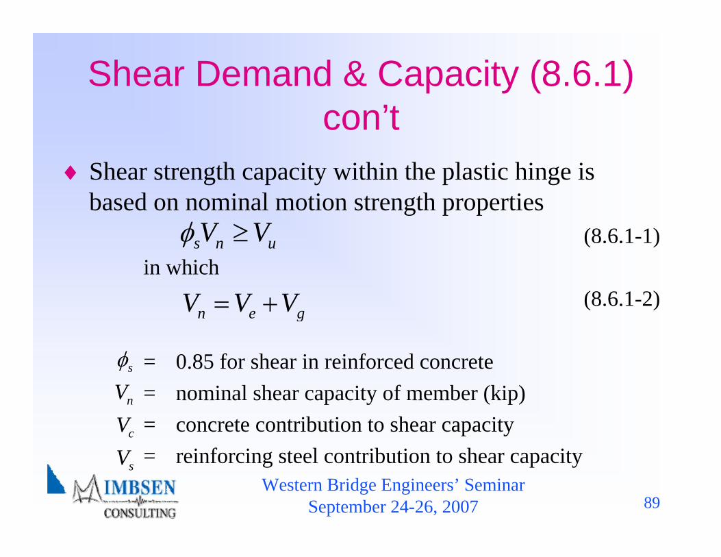
(8.6.1-1)in which
(8.6.1-2)
= 0.85 for shear in reinforced concrete= nominal shear capacity of member (kip)= concrete contribution to shear capacity= reinforcing steel contribution to shear capacity
Shear Demand & Capacity (8.6.1) con’t
♦ Shear strength capacity within the plastic hinge is based on nominal motion strength properties
n e gV V V= +
s n uV Vφ ≥
sφ
nV
cV
sV

Western Bridge Engineers’ SeminarSeptember 24-26, 2007 90
Concrete Shear Capacity SDC B, C & D (8.6.2)
(8.6.2-1)
(8.6.2-2)If Pc is compressive then
(8.6.2-3)Otherwise (i.e., not compression)
(8.6.2-4)
0.8e gA A=
c c eV v A=
0cv =
0.110.032 {1 }
2 0.047cu
c cg c
fPv fA f
αα
⎧ ⎫′⎧ ⎫⎪ ⎪ ⎪ ⎪′ ′= + ≤⎨ ⎬ ⎨ ⎬′⎪ ⎪ ⎪ ⎪⎩ ⎭ ⎩ ⎭
Western Bridge Engineers’ SeminarSeptember 24-26, 2007 91
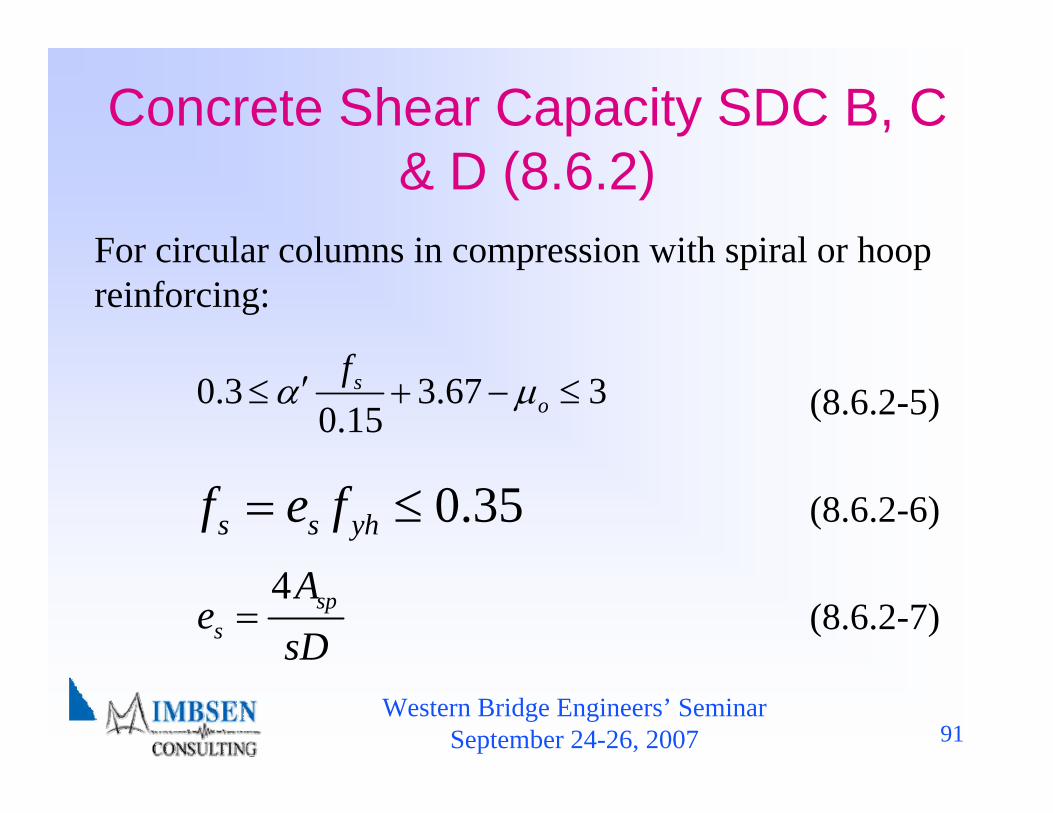
Concrete Shear Capacity SDC B, C & D (8.6.2)
For circular columns in compression with spiral or hoop reinforcing:
(8.6.2-5)
(8.6.2-6)
(8.6.2-7)4 sp
s
Ae
sD=
0.3 3.67 30.15
so
fα μ′≤ + − ≤
0.35s s yhf e f= ≤
Western Bridge Engineers’ SeminarSeptember 24-26, 2007 92
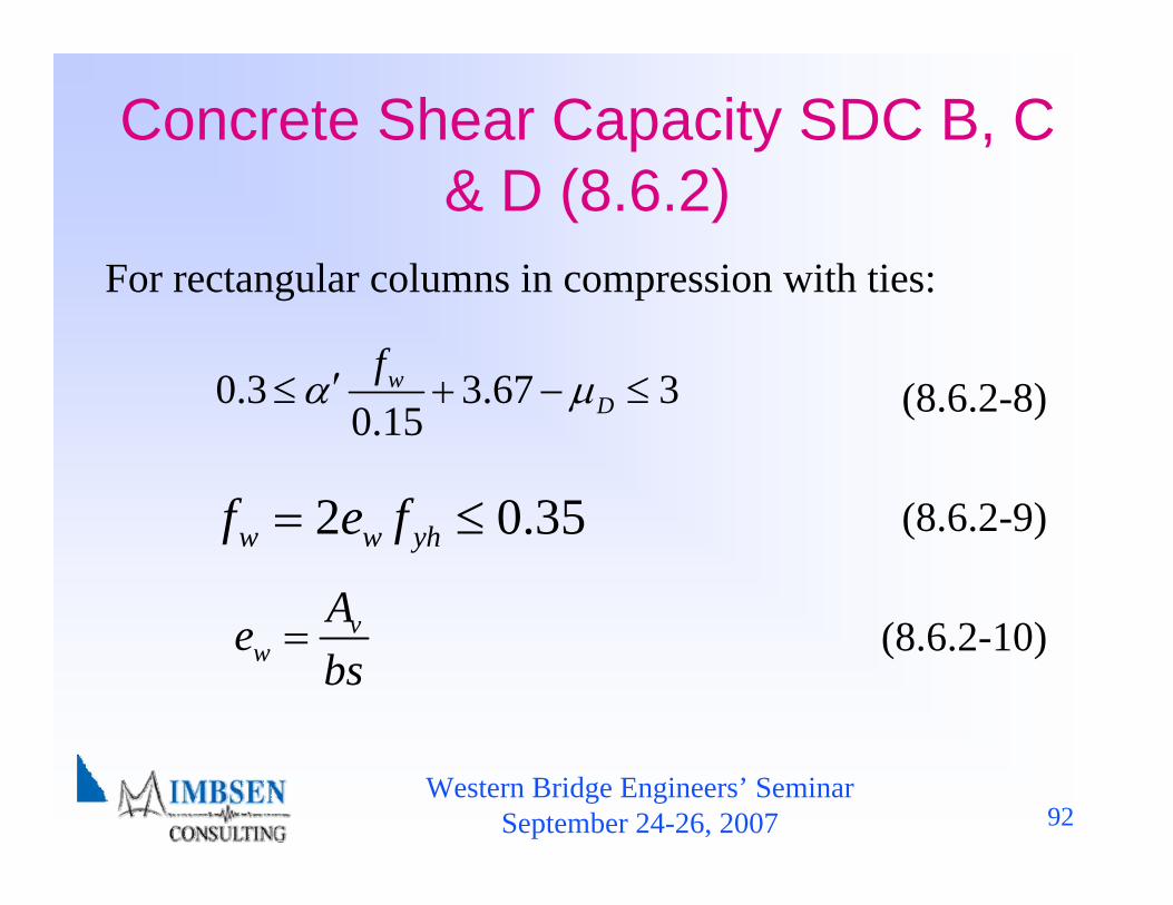
Concrete Shear Capacity SDC B, C & D (8.6.2)
For rectangular columns in compression with ties:
(8.6.2-8)
(8.6.2-9)
(8.6.2-10)vw
Aebs
=
0.3 3.67 30.15
wD
fα μ′≤ + − ≤
2 0.35w w yhf e f= ≤
Western Bridge Engineers’ SeminarSeptember 24-26, 2007 93
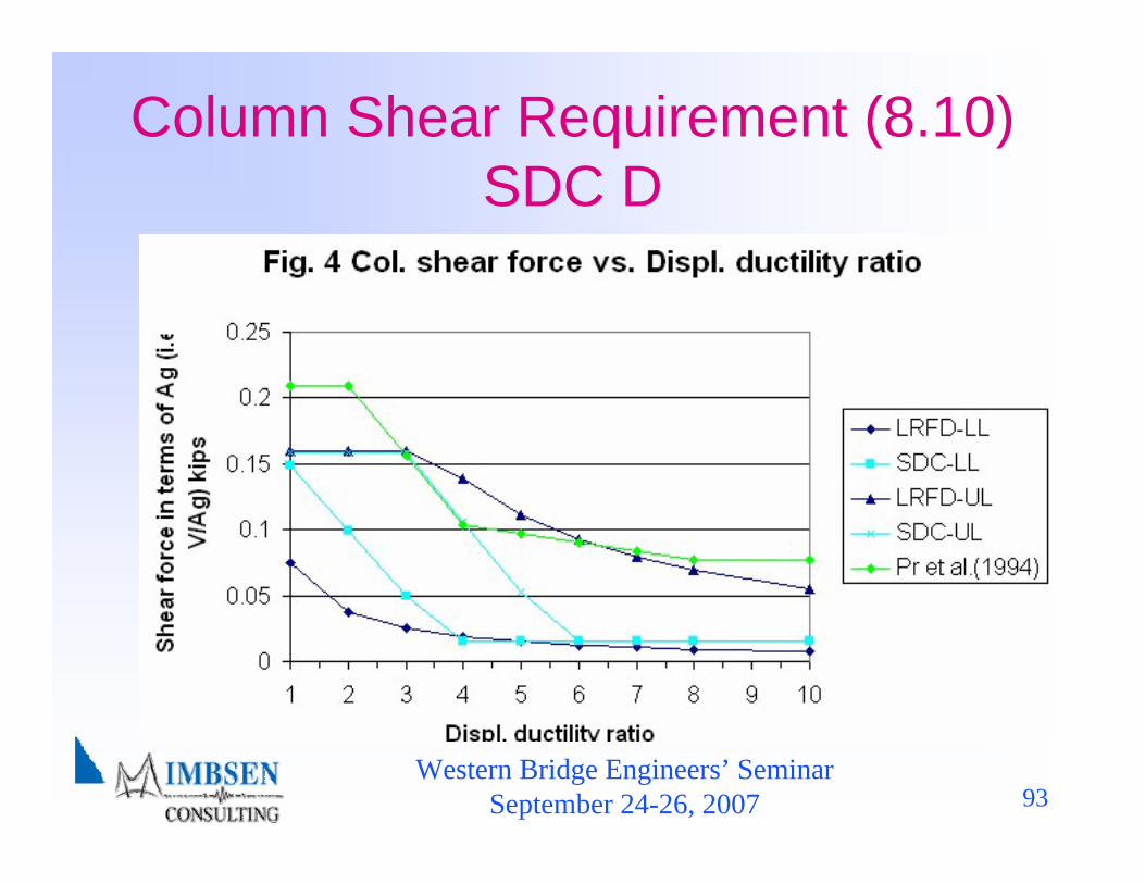
Column Shear Requirement (8.10) SDC D
Western Bridge Engineers’ SeminarSeptember 24-26, 2007 94
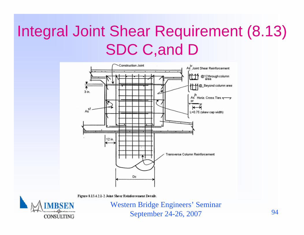
Integral Joint Shear Requirement (8.13) SDC C,and D
Western Bridge Engineers’ SeminarSeptember 24-26, 2007 95
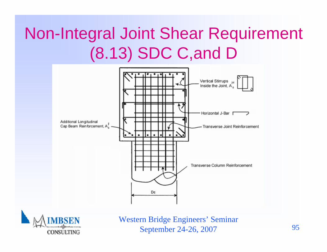
Non-Integral Joint Shear Requirement (8.13) SDC C,and D
Western Bridge Engineers’ SeminarSeptember 24-26, 2007 96
Presentation Topics ♦Background-AASHTO LRFD Guide Specifications♦Excerpts selected from the Guide Specifications♦AASHTO T-3 Committee recent activities
supporting adoption as a Guide Specification♦Current status♦Planned activities post-adoption♦Conclusions
Western Bridge Engineers’ SeminarSeptember 24-26, 2007 97
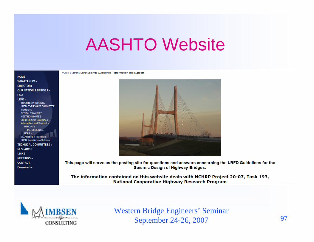
AASHTO Website

Western Bridge Engineers’ SeminarSeptember 24-26, 2007 98
Presentation Topics ♦Background-AASHTO LRFD Guide Specifications♦Excerpts selected from the Guide Specifications♦AASHTO T-3 Committee recent activities
supporting adoption as a Guide Specification♦Current status♦Planned activities post-adoption♦Conclusions
Western Bridge Engineers’ SeminarSeptember 24-26, 2007 99
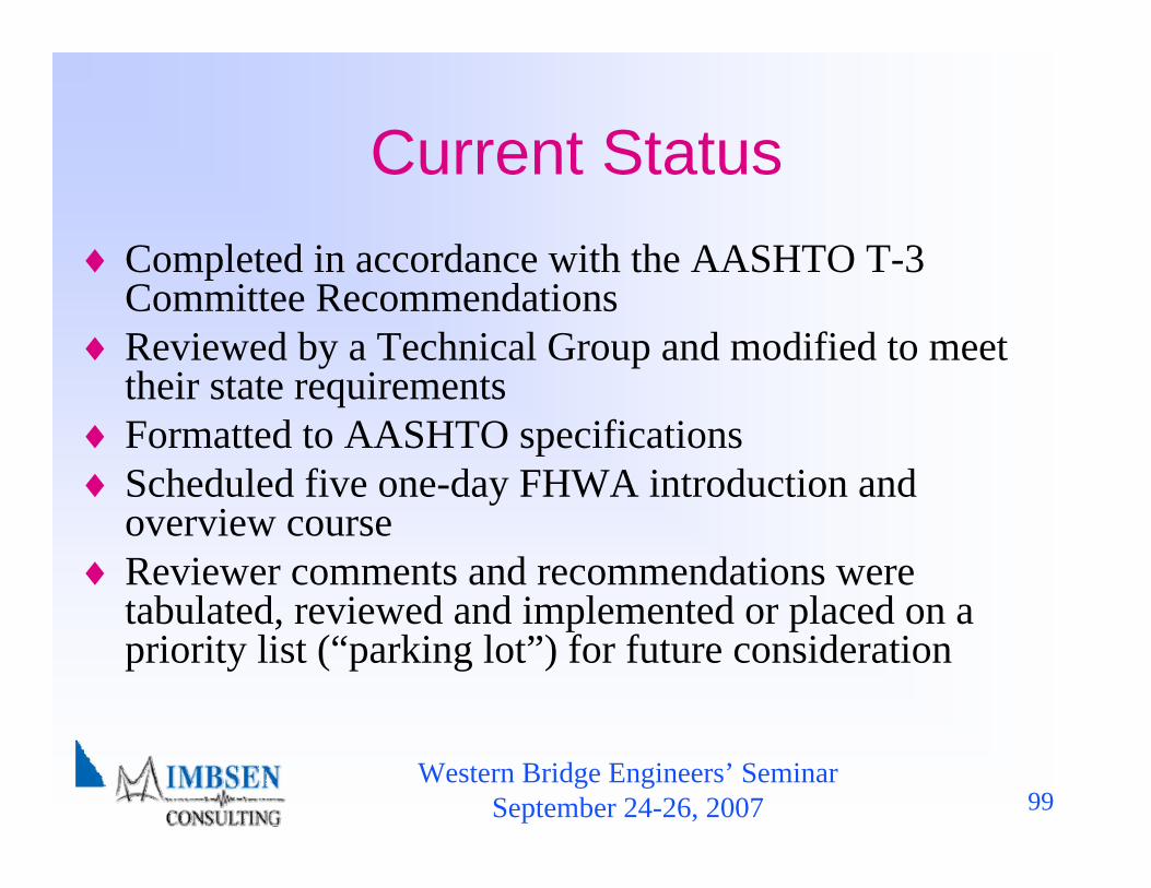
Current Status♦ Completed in accordance with the AASHTO T-3
Committee Recommendations♦ Reviewed by a Technical Group and modified to meet
their state requirements♦ Formatted to AASHTO specifications♦ Scheduled five one-day FHWA introduction and
overview course♦ Reviewer comments and recommendations were
tabulated, reviewed and implemented or placed on a priority list (“parking lot”) for future consideration
Western Bridge Engineers’ SeminarSeptember 24-26, 2007 100
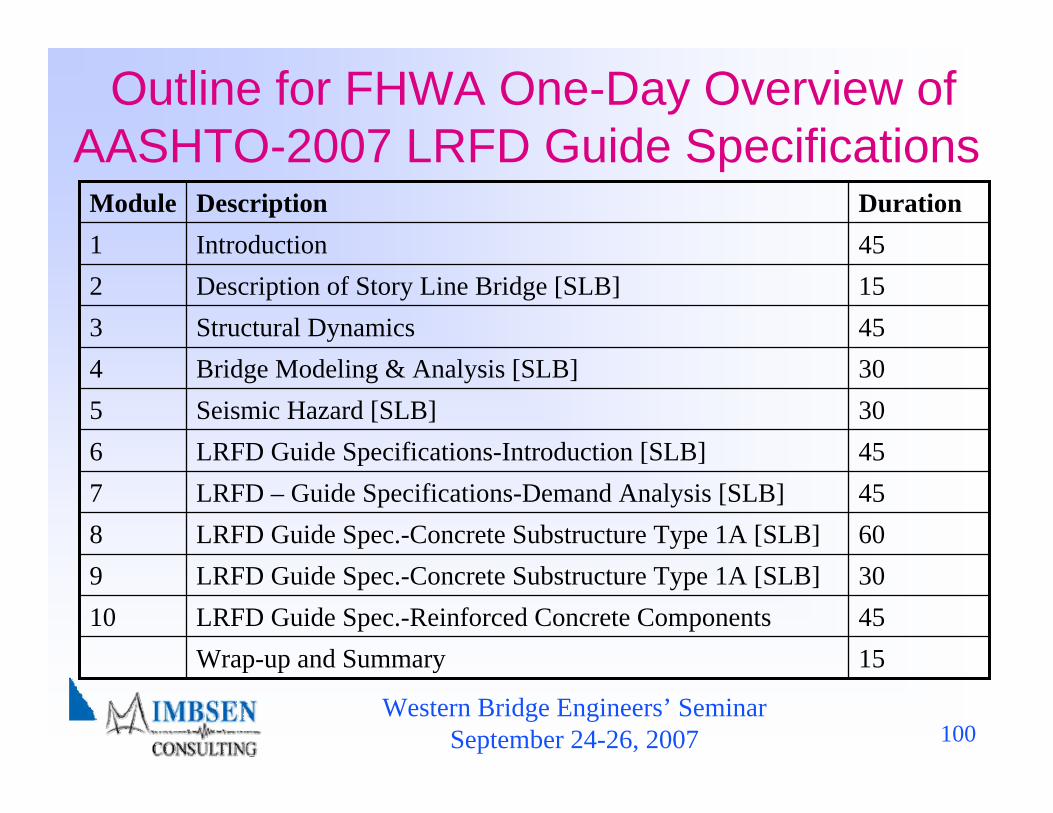
Outline for FHWA One-Day Overview of AASHTO-2007 LRFD Guide Specifications
15Wrap-up and Summary45LRFD Guide Spec.-Reinforced Concrete Components1030LRFD Guide Spec.-Concrete Substructure Type 1A [SLB]960LRFD Guide Spec.-Concrete Substructure Type 1A [SLB]845LRFD – Guide Specifications-Demand Analysis [SLB]745LRFD Guide Specifications-Introduction [SLB]630Seismic Hazard [SLB]530Bridge Modeling & Analysis [SLB]445Structural Dynamics315Description of Story Line Bridge [SLB]245Introduction1DurationDescriptionModule
Western Bridge Engineers’ SeminarSeptember 24-26, 2007 101
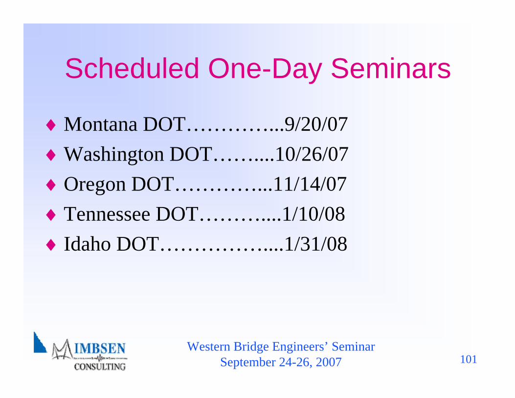
Scheduled One-Day Seminars
♦Montana DOT…………...9/20/07♦Washington DOT……....10/26/07♦Oregon DOT…………...11/14/07♦Tennessee DOT………....1/10/08♦Idaho DOT……………....1/31/08
Western Bridge Engineers’ SeminarSeptember 24-26, 2007 102
Planned Activities-Post Adoption
♦Development of an FHWA funded training manual and course geared toward practicing engineer
♦Review of the geotechnical issues addressed in the comments and recommendations
♦Address tabulated comments and recommendations placed in a “parking lot” as funding becomes available
Section 5.3

Western Bridge Engineers’ SeminarSeptember 24-26, 2007 103
Conclusions♦ Adopted as a Guide Specifications ♦ Developed a specification that is user friendly and implemental
into production design♦ Logical progression from the current AASHTO force-based
seismic design criteria to a displacement-based criteria♦ Technical reviewers were focused on making adjustments to
bridge the gap between the seismic design approaches to ease the implementation of the displacement-based approach
♦ Computer software is available to assist the designer, Computers& Structures Inc. (CSI) is enhancing SAP 2000 to be used with the new 2007 Guide Specifications
♦ Lets do it !!!!!!!!