Embed Size (px)
Citation preview

8/23/2019 AAR Intermodal Interchange Rules
http://slidepdf.com/reader/full/aar-intermodal-interchange-rules 1/224
Association of American Railroads
Safety and Operations425 Third Street SW
Washington, DC 20024
Governing the Interchange of, Repairs to, andSettlement for, Units Used in
Intermodal Service
Effective November 1, 2010
AAR Intermodal Interchange Rules
Including Billing and Repair Procedures

8/23/2019 AAR Intermodal Interchange Rules
http://slidepdf.com/reader/full/aar-intermodal-interchange-rules 2/224

8/23/2019 AAR Intermodal Interchange Rules
http://slidepdf.com/reader/full/aar-intermodal-interchange-rules 3/224
Changes incorporated in the November 1, 2010, version of the Intermodal Interchange Rules arelisted below:
Restored numbers to ranges of vacant rules throughout book and included them in Contents. ....iRule 2—added paragraph............................................................................................................. 1Rule 3b—Revised......................................................................................................................... 1
Rule 11—Deleted reference to Appendix B.................................................................................. 4Rule 27b(7)—Deleted ................................................................................................................... 8Rule 27b(8)—Renumbered to 27b(7) ........................................................................................... 8Rule 27b(9)—Renumbered to 27b(8) ........................................................................................... 8Rule 81h—Added........................................................................................................................ 18Rule 82e through 82h—Added ................................................................................................... 18Rule 121—Moved definition of recorded image to Appendix C .................................................. 27Rule 122a(5)—Revised............................................................................................................... 28Rule 122c—Deleted.................................................................................................................... 28Rule 136—Revised..................................................................................................................... 39Rule 138—Revised..................................................................................................................... 39Rule 139—Revised..................................................................................................................... 40
Rule 156a—Added paragraph .................................................................................................... 43Rule 156b—Revised; added Table 1: Depreciated Value Table ................................................ 43Rule 156c—Revised ................................................................................................................... 45Rule 157—Revised..................................................................................................................... 45Rule 171b—Revised................................................................................................................... 51Rule 171c—Added...................................................................................................................... 51Rule 173a—Revised................................................................................................................... 56Rules 182 through 184—Titles and paragraph numbers added to text to retain consistency withother sections; revised Web site URLs. ...................................................................................... 61Rule 185—Added title and paragraph number above existing text to retain consistency with other sections....................................................................................................................................... 63Rules 185a through 185f—Revised............................................................................................ 63Rule A10—Added Why Made Codes.......................................................................................... 71Figure B-21—Clarified dimensions ........................................................................................... 115Rule B14c—Added ................................................................................................................... 127Rule C1—Added; renumbered subsequent paragraphs........................................................... 133Rule C1—Added new term "Recorded Image" ......................................................................... 133Rule C4—Revised term "Diaphragm" ....................................................................................... 140
Appendix F—Added introductory text and updated throughout................................................ 151

8/23/2019 AAR Intermodal Interchange Rules
http://slidepdf.com/reader/full/aar-intermodal-interchange-rules 4/224
8/23/2019 AAR Intermodal Interchange Rules
http://slidepdf.com/reader/full/aar-intermodal-interchange-rules 5/224
11/1/2010 –i–
AAR Intermodal Interchange Rules
Contents
Preamble .................................................................................................................................... xiiiPreface ....................................................................................................................................... xiii
SECTION A—GENERAL CONDITIONS GOVERNING ACCEPTANCE AND DELIVERYOF UNITS IN INTERCHANGE......................................................................................................1
1. Equipment Specifications.............................................................................................1
2. Hazmat Placarding.......................................................................................................1
3. Loading Practices ........................................................................................................1
4. Clearance Profile .........................................................................................................1
5. Weight Restrictions......................................................................................................1
6. Electrical Connector.....................................................................................................1
7. Lights ...........................................................................................................................2
8. Tank Containers...........................................................................................................3
a. Compliance Certification....................................................................................3
b. Loading Conditions ............................................................................................3
c. Tank Data Plate..................................................................................................3
d. Tank and Safety Relief Valve .............................................................................3
e. Inspection ..........................................................................................................3
9. Tank Trailers (“Cargo Tanks”) Carrying Materials ........................................................3
10. Document Holder .........................................................................................................3
11. Tires.............................................................................................................................4
12. Landing Gear ...............................................................................................................4
13. Licensing......................................................................................................................4
14. Interchange Placement................................................................................................4
a. Rail Interchange.................................................................................................4
b. Rubber Interchange ...........................................................................................4
15. Defective Units.............................................................................................................4
16. Vacant ..........................................................................................................................4
17. Gasoline/LPG Refrigeration Units................................................................................4
18. Portable Heater Units...................................................................................................5
19. Equipment Registration and Reporting........................................................................5
a. Equipment Initial/Number ..................................................................................5
b. TRAIN II and UMLER Reporting........................................................................5
20. Kingpin Wear Limits .....................................................................................................5
21. to 25. Vacant ................................................................................................................5
SECTION B—TIRES AND TUBES...............................................................................................7
26. Conditions at Time of Acceptance and in Interchange ................................................7
a. Presence of Tires and Wheel Lugs....................................................................7
b. Suitability of Tires and Rims ..............................................................................7
c. Tire Markings .....................................................................................................7
d. Lack of Foreign Objects.....................................................................................7
e. Inflation and Mating ...........................................................................................7
27. Maintenance, Repair, and Replacement......................................................................7
a. Trailer or Chassis Owner Responsibility ............................................................7
b. Handling Line Responsibility..............................................................................7

8/23/2019 AAR Intermodal Interchange Rules
http://slidepdf.com/reader/full/aar-intermodal-interchange-rules 6/224 –ii– 11/1/2010
AAR Intermodal Interchange Rules
(1) Maintenance...........................................................................................8
(2) Unserviceable Tires................................................................................8
(3) Rims .......................................................................................................8
(4) Serviceable Tubes..................................................................................8
(5) Unserviceable Tubes..............................................................................8
(6) Booting, Sectioning, or Vulcanizing........................................................8
(7) Exchanging of Tires................................................................................8
(8) Multiple Renewals and Replacement at Terminals and byContracted Vendors................................................................................8
c. Repair, Renewal, and Replacement Procedures ...............................................8
(1) Tire Repair Billing Form..........................................................................9
(2) Inspection and Collection of Unserviceable Tires...................................9
(3) Retention Period.....................................................................................9
28. to 40. Vacant ................................................................................................................9
SECTION C—LANDING GEARS...............................................................................................11
41. Conditions at Time of Acceptance and in Interchange ..............................................11a. Load Support ...................................................................................................11
b. Condition and Securement .............................................................................. 11
c. Clearances.......................................................................................................11
42. Maintenance and Operation ......................................................................................11
a. Maintenance, Repairs, and Lubrication ........................................................... 11
b. Raising Landing Gear ......................................................................................11
c. Lowering Landing Gear....................................................................................11
43. to 54. Vacant ..............................................................................................................11
SECTION D—REFRIGERATION AND HEATING .....................................................................13
55. Conditions at Time of Acceptance and in Interchange for Mechanical Units.............13a. Stenciling/Fuel type .........................................................................................13
b. Satisfactory Operating Condition.....................................................................13
c. Sufficient Oil and fuel .......................................................................................13
56. Vacant........................................................................................................................13
57. Maintenance ..............................................................................................................13
58. Portable Units ............................................................................................................13
59. to 70. Vacant ..............................................................................................................13
SECTION E—ACCESSORIES AND SPECIAL EQUIPMENT ...................................................15
71. Removable Items/Stenciling ......................................................................................15
72. Delivering Carrier Responsibility................................................................................1573. Handling Carrier Responsibility .................................................................................15
a. Securement of Equipment ...............................................................................15
b. Tarpaulins and Bows—Loaded Trailers ...........................................................15
c. Equipment—Empty Trailers .............................................................................16
74. to 80. Vacant ..............................................................................................................16
SECTION F—HANDLING CARRIER RESPONSIBILITY ..........................................................17
81. Damage—By Causes ................................................................................................17
82. Damage—Evidential..................................................................................................18
83. Losses .......................................................................................................................18

8/23/2019 AAR Intermodal Interchange Rules
http://slidepdf.com/reader/full/aar-intermodal-interchange-rules 7/224
11/1/2010 –iii–
AAR Intermodal Interchange Rules
84. Contamination Commodities......................................................................................18
a. Loading Restriction ..........................................................................................18
b. Reporting Contaminating Loadings..................................................................19
85. Temporary Repairs.....................................................................................................19
86. Damage by Non-AAR Member ..................................................................................19
a. Railroad-Owned or Leased Units.....................................................................19
b. Non-Railroad-Owned or Leased Units.............................................................19
87. Vacant ........................................................................................................................19
SECTION G—ORDINARY MAINTENANCE ..............................................................................21
88. Owner Responsibility .................................................................................................21
89. to 94. Vacant ..............................................................................................................22
SECTION H—REPAIRS AND BILLING .....................................................................................23
95. Detailed Procedures ..................................................................................................23
96. Repairs Exceeding $450............................................................................................23
97. Handling Line Responsibility......................................................................................2398. Repair Cost Limit .......................................................................................................23
99. Standards for Repair ..................................................................................................23
100. Safety—Conditioning for Loading ..............................................................................23
101. Repairs Requiring Authorization ................................................................................23
102. Citations.....................................................................................................................24
103. to 109. Vacant ............................................................................................................24
SECTION I—ADJUSTMENT OR TRANSFER OF TRAILERS AND/OR LADING ....................25
110. Delivering Carrier Responsibility................................................................................25
a. Compliance with Loading Rules ......................................................................25
b. Adjustment/Transfer of Units and Lading.........................................................25(1) Shifted Contents/Improper Loading ......................................................25
(2) Defective Trailer or Container...............................................................25
(3) Defective Car/Attachment.....................................................................25
111. Originating Carrier Responsibility ..............................................................................25
a. Transfer—Clearance Violation.........................................................................25
b. Transfer and Delivery—Overload ....................................................................25
c. Damage—Overload .........................................................................................25
112. to 119. Vacant ............................................................................................................25
SECTION J—FORMS AND REPORTS......................................................................................27
120. General Instructions...................................................................................................27121. Unit Interchange and Safety Inspection Report, Form J-1.........................................27
122. Unit Damage Responsibility Report, Form J-2...........................................................27
a. Preparation and Use of Form...........................................................................27
(1) Damage Form and Distribution.............................................................27
(2) Recorded Image ...................................................................................27
(3) Interchange with Unrepaired Damage Not Covered by Form...............27
(4) Time Limit for Repair ............................................................................28
(5) Associated Damage .............................................................................28
b. Exception to Form............................................................................................28

8/23/2019 AAR Intermodal Interchange Rules
http://slidepdf.com/reader/full/aar-intermodal-interchange-rules 8/224 –iv– 11/1/2010
AAR Intermodal Interchange Rules
c. Provision of Rebill Authority .............................................................................28
123. Authority for Adjustment or Transfer of Unit or Lading, Form J-3 ..............................28
a. Preparation and Use of Form ..........................................................................28
b. Expense Responsibility....................................................................................28
124. Vacant........................................................................................................................29
125. Authority for Counterbilling, Form J-5 ........................................................................29
a. Purpose ...........................................................................................................29
b. Completion of Form .........................................................................................29
126. FHWA-PI Certification, Form J-6 ...............................................................................29
127. FHWA-PI Certification Acknowledgment, Form J-7...................................................30
128. AAR Flat File Format .................................................................................................30
129. to 135. Vacant ............................................................................................................30
SECTION K—SETTLEMENT OF DISPUTES AND REVISION OF RULES..............................39
136. Arbiter of Rules..........................................................................................................39
137. Interpretation of Rules ...............................................................................................39
138. Formal Arbitration ......................................................................................................39
a. Material to be Submitted..................................................................................39
(1) Both Parties Agree to Arbitration..........................................................39
(2) One Party Declines to Submit to Arbitration.........................................39
b. Procedures ......................................................................................................40
(1) Roles ....................................................................................................40
(2) Statements............................................................................................40
(3) Presence of Principals..........................................................................40
(4) Finality ..................................................................................................40
139. Rules Revisions.........................................................................................................40
140. to 155. Vacant ............................................................................................................41
...................................................................................................................................42
SECTION L—SETTLEMENT FOR DESTROYED, BADLY DAMAGED, ORSTOLEN UNITS—HANDLING CARRIER RESPONSIBILITY ...................................................43
156. Destroyed, Badly Damaged, or Stolen Units .............................................................43
a. Notification, Depreciated Value, and Disposition .............................................43
b. Repair Costs Over Limit...................................................................................43
c. Salvage Value ..................................................................................................45
157. Handling Line Repair .................................................................................................45
158. Units Requested Home for Repairs ...........................................................................45
159. Equipment Types.......................................................................................................45
a. Van...................................................................................................................45b. Insulated Van ...................................................................................................45
c. Open Top .........................................................................................................45
d. Platform ...........................................................................................................45
e. Flat Bed ...........................................................................................................45
f. Extendable........................................................................................................45
g. Reefer/Heater ..................................................................................................45
h. Other................................................................................................................46
i. Container ..........................................................................................................46
j. Chassis .............................................................................................................46

8/23/2019 AAR Intermodal Interchange Rules
http://slidepdf.com/reader/full/aar-intermodal-interchange-rules 9/224
11/1/2010 –v–
AAR Intermodal Interchange Rules
k. Extendable Chassis .........................................................................................47
l. Bogie.................................................................................................................47
m. Axle Assemblies .............................................................................................47
n. Wheel Assemblies ...........................................................................................47
o. Rail-Compatible Trailer ....................................................................................47
p. Tank Containers ...............................................................................................47
q. Tank Trailer ......................................................................................................47
r. Genset ..............................................................................................................47
160. to 164. Vacant ............................................................................................................48
SECTION M—SETTLEMENT FOR DEFECTIVE UNITS—OWNER’S RESPONSIBILITY........49
165. Notification .................................................................................................................49
166. Disposition .................................................................................................................49
a. Return Home ...................................................................................................49
(1) Dispute .................................................................................................49
b. Disposal ...........................................................................................................49
167. to 170. Vacant ............................................................................................................49
SECTION N—LOCATIONS, MARKINGS, AND AEI..................................................................51
171. Location Designations ...............................................................................................51
a. Front/Rear.......................................................................................................51
b. Sides and Top ..................................................................................................51
c. Tires and Axles ................................................................................................51
172. Stenciling—Weight, Height, Capacity ........................................................................52
a. Alteration of Stencils ........................................................................................52
b. Included in Empty Weight ................................................................................52
173. Reporting Marks and Numbers..................................................................................56
a. Trailers or Containers ......................................................................................56b. Bogies and Chassis .........................................................................................56
c. Non-Satisfactory Markings...............................................................................56
d. Short Term Leasing..........................................................................................56
e. Change in Status .............................................................................................56
174. Hazardous Placards...................................................................................................56
175. Automatic Equipment Identification............................................................................57
176. to 179. Vacant ............................................................................................................57
...................................................................................................................................58
SECTION O—CONDITIONS OF ACCEPTANCE.......................................................................59
180. Vacant ........................................................................................................................59181. Acceptance of Rules..................................................................................................59
SECTION P—SUBSCRIPTION TO THE INTERMODAL INTERCHANGE RULES...................61
183. Subscription ...............................................................................................................61
184. Availability ..................................................................................................................61
SECTION Q—PROPOSED CHANGES TO AAR INTERMODAL INTERCHANGE RULES .....63
185. Procedure for Proposing Changes.............................................................................63
APPENDIX A—BILLING PROCEDURES ..................................................................................65
8/23/2019 AAR Intermodal Interchange Rules
http://slidepdf.com/reader/full/aar-intermodal-interchange-rules 10/224 –vi– 11/1/2010
AAR Intermodal Interchange Rules
A1. Required Documents.................................................................................................65
a. Form J-2 ..........................................................................................................65
b. FHWA Inspections ...........................................................................................65
A2. Repair Records..........................................................................................................65
a. Generation and Retention................................................................................65b. Required Information .......................................................................................65
A3. Billing Categories.......................................................................................................65
A4. Billing Formats...........................................................................................................66
A5. Mechanized Billing.....................................................................................................66
d. Required Information: ......................................................................................66
A6. Vacant........................................................................................................................67
A7. Exceptions .................................................................................................................67
A8. No Bills.......................................................................................................................67
A9. Handling of Bills .........................................................................................................68
a. Calculation Date of Charges............................................................................68
b. Owner Responsibility.......................................................................................68c. J-2 Repairs.......................................................................................................68
d. Consolidation of Charges ................................................................................68
e. Time Limits ......................................................................................................68
f. Corrections/Counterbilling ................................................................................68
g. Lost Bills ..........................................................................................................69
h. Units Retired vs. Repaired...............................................................................70
A10. Condition, Why Made, Responsibility, and Location Codes ......................................70
A11. Organization of Job Codes ........................................................................................74
a. 1000–1999—Tires/Rims ..................................................................................74
b. 2000–2799—Suspension and Tandems..........................................................74
c. 2800–2999—Air Ride.......................................................................................74
d. 3000–3999—Unders Construction—Below Floor, Except Tandem .................74
e. 4000–4999—Body Construction......................................................................74
f. 5000–5099—Chassis Frame............................................................................74
g. 5100–5299—Chassis Rack .............................................................................74
h. 5300–5399—Containers..................................................................................74
i. 5400–5899—Miscellaneous..............................................................................74
j. 5900–5999—Vacant .........................................................................................74
k. 6000–6299—Mechanical Refrigeration/Heater Units.......................................74
l. 6300–6499—Vacant .........................................................................................74
m. 6500–6799—Tank Containers ........................................................................74
n. 6800–6990—Vacant ........................................................................................74
o. 6991–6999—Taxes..........................................................................................74
p. 7000–7999—Reserved for Expansion.............................................................74
q. 8000–9999—Reserved for Individual Railroads ..............................................74
APPENDIX B—CORRECT UNIT REPAIR PROCEDURES.......................................................75
B1. Introduction................................................................................................................75
a. Preface ............................................................................................................75
b. Proper Repairs.................................................................................................75
c. Equipment Component Compatibility...............................................................75

8/23/2019 AAR Intermodal Interchange Rules
http://slidepdf.com/reader/full/aar-intermodal-interchange-rules 11/224
11/1/2010 –vii–
AAR Intermodal Interchange Rules
d. Owner’s Requirements ....................................................................................75
e. Tamper Evidence Requirement .......................................................................75
B2. General Trailer/Container Repairs .............................................................................76
a. Post and Panel Damage..................................................................................76
b. Joining Dissimilar Materials .............................................................................76(1) Joining Aluminum to Unfinished Steel or Stainless Steel......................76
(2) Joining Aluminum and Wood Components...........................................76
(3) Joining Metal to FRP Panels ................................................................77
B3. Body Repairs (Side Panels).......................................................................................77
a. Mating of Panels..............................................................................................77
b. Patching Body Panels of Sheet and Post Trailers and Containers..................77
c. Patching Body Panel of Steel Container ..........................................................79
(1) Straightening.........................................................................................79
(2) Straightening and Welding....................................................................79
(3) Inserting................................................................................................79
d. Panel Replacement of Sheet and Post Trailers and Containers......................80e. ) Panel Replacement of Steel Box Containers.................................................81
f. FRP Panel Damage..........................................................................................81
(1) General.................................................................................................81
(2) Damage Categories..............................................................................81
(3) Non-Puncture Damage Repair .............................................................82
(4) Surface Repair......................................................................................82
(5) Replacement of Damaged Section.......................................................82
B4. General Interior Repairs.............................................................................................84
a. Floors...............................................................................................................84
(1) Floor Structure and Damage ................................................................84
(2) Flooring Repairs ...................................................................................85b. Side Liners.......................................................................................................86
c. Scuff Liner........................................................................................................86
d. Roof .................................................................................................................87
B5. Trailer or Chassis Support Repairs............................................................................87
a. Landing Legs ...................................................................................................87
(1) Description............................................................................................87
(2) Defects .................................................................................................90
(3) Repair Comparability Required.............................................................90
(4) Component Replacement vs. Leg Replacement ..................................90
(5) Landing Gear Mounting Bracket...........................................................90
(6) Sand Shoes, Dolly Wheels, and Axles .................................................90(7) Landing Gear Crank Handle.................................................................91
(8) Cross Shaft...........................................................................................91
B6. Roof Repairs ..............................................................................................................91
a. General ............................................................................................................91
b. Patching Roof Sheet........................................................................................92
c. Roof Sheet Breaks More Than 6 Inches..........................................................93
d. Roof Replacement—Aluminum (Dry Van or Container)...................................94
e. Roof Bows .......................................................................................................94
B7. Rear Doors and Rear Frame .....................................................................................94

8/23/2019 AAR Intermodal Interchange Rules
http://slidepdf.com/reader/full/aar-intermodal-interchange-rules 12/224 –viii– 11/1/2010
AAR Intermodal Interchange Rules
a. General ............................................................................................................94
b. Repair Procedures...........................................................................................97
(1) Rear Doors ...........................................................................................97
(2) Security Hardware................................................................................97
(3) Rear Door Frame..................................................................................98
B8. Splicing of Side Rails and Protectors.........................................................................98
a. Repair Procedures...........................................................................................98
(4) Splice Plates.........................................................................................98
(7) Stretch Trailers .....................................................................................98
b. Definitions........................................................................................................99
(1) Top Rail Protectors ...............................................................................99
(2) Lift Pads (Bottom Rail Protectors) ......................................................100
B9. Riveting....................................................................................................................102
a. General ..........................................................................................................102
b. Inspection Procedures for Locating Defective or Loose Rivets .....................102
c. Proper Riveting Procedures...........................................................................103(2) Tools ...................................................................................................103
B10. Axles, Bearings, and Brakes....................................................................................107
a. General ..........................................................................................................107
b. Brakes............................................................................................................107
(1) Brake Inspection.................................................................................107
(2) Brake Adjustments .............................................................................107
(3) Spring Brake Chambers .....................................................................108
(4) Brake Liners .......................................................................................108
B11. Upper Coupler and Kingpin .....................................................................................112
a. Kingpin...........................................................................................................112
(1) Repair Restriction............................................................................... 112(2) Kingpin Wear Limits............................................................................112
b. Upper Coupler ............................................................................................... 113
B12. Subassembly ........................................................................................................... 117
a. Locking Mechanisms .....................................................................................118
(1) Types..................................................................................................118
(2) Safety Requirement............................................................................118
b. Guide and Hold-Down Brackets .................................................................... 118
c. Maintenance ..................................................................................................118
d. Air Rides ........................................................................................................ 119
B13. Electrical and Air Systems.......................................................................................122
a. Electrical System ...........................................................................................122(1) Lighting System..................................................................................122
(2) Protective Coating ..............................................................................122
(3) Welding...............................................................................................122
b. Air System .....................................................................................................123
(1) Air Relay Valve Replacement.............................................................123
(2) Drain Cock Manual Replacement.......................................................123
(3) Glad Hand Placement ........................................................................123
B14. Tires.........................................................................................................................126
a. Safety Precautions.........................................................................................126

8/23/2019 AAR Intermodal Interchange Rules
http://slidepdf.com/reader/full/aar-intermodal-interchange-rules 13/224
11/1/2010 –ix–
AAR Intermodal Interchange Rules
b. Inflation ..........................................................................................................127
c. Slid Flat Tires .................................................................................................127
d. Minimum Standard for Retreading and Repairing Bias Ply Tires...................127
(1) Purpose ..............................................................................................127
(2) Scope .................................................................................................127
(3) Definitions...........................................................................................127
(4) Casing Inspection and Selection for Retreading ................................127
(5) Processing..........................................................................................128
(6) Final Inspection ..................................................................................130
(7) Finished Product.................................................................................130
B15. DOT Underride Guard..............................................................................................131
APPENDIX C—GLOSSARY.....................................................................................................133
C1. General Terms .........................................................................................................133
C2. Trailer Component Glossary ....................................................................................133
C3. Container Component Glossary...............................................................................137C4. Tire Glossary............................................................................................................139
APPENDIX D—FLAT FILE FORMAT.......................................................................................147
D1. Introduction ..............................................................................................................147
D2. J File Format............................................................................................................147
D3. J2 Format.................................................................................................................147
a. Header Fields ................................................................................................147
b. Line Item Fields .............................................................................................148
D4. Reading The File .....................................................................................................148
APPENDIX E—SUBSCRIBERS TO THE INTERMODAL INTERCHANGE AGREEMENT ....149E1. Railroad Companies ................................................................................................149
E2. Non-Railroad Companies.........................................................................................150
APPENDIX F—COMPLETE MATRIX.......................................................................................151...................................................................................................................................................151

8/23/2019 AAR Intermodal Interchange Rules
http://slidepdf.com/reader/full/aar-intermodal-interchange-rules 14/224 –x– 11/1/2010
AAR Intermodal Interchange Rules

8/23/2019 AAR Intermodal Interchange Rules
http://slidepdf.com/reader/full/aar-intermodal-interchange-rules 15/224
11/1/2010 –xi–
AAR Intermodal Interchange Rules
List of Figures
Figure 1 — Connector Socket ...........................................................................................................2
Figure 2 — Form J-1 — Unit Interchange and Safety Inspection Form ..........................................31
Figure 3 — Form J-2 — Intermodal Equipment Damage Report ....................................................32Figure 4 — Vacant...........................................................................................................................33
Figure 5 — Form J-3 — Authority for Transfer or Adjustment of Intermodal Equipment or Intermodal Lading.........................................................................................................34
Figure 6 — Vacant...........................................................................................................................35
Figure 7 — Form J-5 — Counterbilling Authority.............................................................................36
Figure 8 — Form J-6 — Federal Highway Administration Periodic Inspection (Sample)................37
Figure 9 — Form J-7 (Sample)........................................................................................................38
Figure 10 — Tank Container............................................................................................................48
Figure 11 — Quad Axle Diagram.....................................................................................................53
Figure 12 — Tri- and Double-Axle Diagram ....................................................................................54
Figure 13 — Axle Diagram (Side)....................................................................................................55Figure 14 — Association of American Railroads Unit Repair Billing Form ......................................72
Figure 15 — Association of American Railroads Tire Repair Billing Form ......................................73
Figure B-1 — Patching Panels ........................................................................................................77Figure B-1a — Patching Panels ......................................................................................................78
Figure B-2 — Panel Insert ...............................................................................................................79
Figure B-3 — Panel Overlay............................................................................................................80
Figure B-4 — Floor Repairs.............................................................................................................85
Figure B-5 — Leg Assembly, Driver ................................................................................................88
Figure B-6 — Support Frames and Supports ..................................................................................89
Figure B-7 — Roof Sheet Edge Treatment......................................................................................92
Figure B-8 — Rear Door Assembly .................................................................................................95Figure B-9 — Rear Frame Assembly ..............................................................................................96
Figure B-10 — “Rule of Thumb” for Trailer Splicing.........................................................................99Figure B-10a — Trailer Lift Pads (Bottom Rail Protectors)............................................................100
Figure B-11 — Splicing of Top Rails ..............................................................................................101
Figure B-12 — Splicing of Bottom Rails ........................................................................................102
Figure B-13 — Proper Rivet Length ..............................................................................................103
Figure B-14 — Good and Bad Rivet Heads ..................................................................................105
Figure B-15 — Solid Rivet Chart — Sizes and Ratings.................................................................106
Figure B-16 — Axle Assembly.......................................................................................................109
Figure B-17 — Axle/Brake Assembly ............................................................................................110
Figure B-17a — Acceptable and Unacceptable Cracks in Shoes .................................................111Figure B-18 — Kingpin Wear Limits ..............................................................................................114
Figure B-19 — Kingpin Nicks, Burrs, Gouges ...............................................................................114
Figure B-20 — Inspection of Kingpin Diameters Using One Type of Gauge.................................115
Figure B-21 — Kingpin Length and Squareness Check Using One Type of Gauge .....................115
Figure B-22 — Front Frame ..........................................................................................................116
Figure B-23 — Floorbed and Frame Assembly .............................................................................117
Figure B-24 — Subframe Assembly, Lower—FS Slider ................................................................120
Figure B-25 — Spring Assembly ...................................................................................................121
Figure B-26 — Air Connections.....................................................................................................124
Figure B-27 — Air Actuation Brake System ..................................................................................125

8/23/2019 AAR Intermodal Interchange Rules
http://slidepdf.com/reader/full/aar-intermodal-interchange-rules 16/224 –xii– 11/1/2010
AAR Intermodal Interchange Rules
Figure C-1 — Trailer Components—Front/Side ............................................................................143
Figure C-2 — Trailer Components—Rear .....................................................................................144
Figure C-3 — Retread Casing—Tubeless Type............................................................................145
Figure C-4 — Buffed Casing—Bias Tubed Type...........................................................................146

8/23/2019 AAR Intermodal Interchange Rules
http://slidepdf.com/reader/full/aar-intermodal-interchange-rules 17/224
11/1/2010 –xiii–
AAR Intermodal Interchange Rules
PREAMBLE
The latest published edition of the Intermodal Interchange Rules shall supersede any previouseditions, updates, circulars, actions, publications and/or dockets intended for inclusion in and/or relating to the Intermodal Interchange Rules
PREFACE
The rules contained herein do not foreclose AAR members from entering into other agreementswhich may be contrary to these rules.
These rules are formulated to provide a means for fair and proper adjustments of questions arisingbetween unit owners and handling companies, with the intent of:
• Making the unit owner responsible for, and therefore chargeable with, repairs to its units,necessitated by ordinary wear and tear in fair service, by safety requirements, by thestandards of the Association of American Railroads, and by the requirements of the variousregulatory agencies controlling highway movement of such equipment.
• Placing responsibility and providing a means of settlement for damage to any unit occurringthrough improper handling or improper protection by the handling company.
• Providing that inspection of unit for interchange will be in accordance with the Code of Rules.
• Assuring that settlement of disputes occurring under other arrangements not invoking theseRules must be settled in accordance with the terms of the agreement or contract betweenthe parties involved.
AAR members agree to accept equipment that is in compliance with these rules, and may accept
other equipment at their individual discretion.
Where the term "units" appears in these rules, it includes all equipment which is designed for use in TOFC/COFC Service, including trailers, containers, and chassis, as defined in Rule 159.
Where the term "owner" appears in these rules, it shall be interpreted to include "lessee," but inany case will be the owner or lessee of record as identified on unit.
Where the term "handling line," or "handling carrier," appears in these rules, it applies to thecarrier in possession of the unit.
Where the term "originating carrier" appears in these rules, it applies to the carrier on which the
unit originates.
Where the term "delivering carrier" appears in these rules, it applies to the carrier, which offersthe unit to another carrier in interchange, at the point of interchange.
Where the term "receiving carrier" appears in these rules, it applies to the carrier, whichaccepts the unit from another carrier in interchange, at the point of interchange.
Where reference to physical documents is made, electronic versions thereof may besubstituted by mutual agreement.

8/23/2019 AAR Intermodal Interchange Rules
http://slidepdf.com/reader/full/aar-intermodal-interchange-rules 18/224 –xiv– 11/1/2010
AAR Intermodal Interchange Rules
THIS PAGE LEFT BLANK INTENTIONALLY

8/23/2019 AAR Intermodal Interchange Rules
http://slidepdf.com/reader/full/aar-intermodal-interchange-rules 19/224
11/1/2010 –1–
AAR Intermodal Interchange Rules
SECTION AGENERAL CONDITIONS
SECTION A
GENERAL CONDITIONS GOVERNING ACCEPTANCE AND DELIVERYOF UNITS IN INTERCHANGE
1. Equipment Specifications
All units shall conform to applicable AAR or ISO Specifications (See AAR Intermodal StandardsM-930, 931, 962, and AAR.600). Units not in conformance with AAR or ISO Specifications in effectas of the date of manufacture may be refused in interchange service.
Should a conflict arise between the AAR and ISO specifications, the AAR specification will takeprecedence.
2. Hazmat Placarding
Trailers and containers containing hazardous materials shall be properly placarded in accordancewith the Hazardous Materials Regulations of the Department of Transportation and such other regulations governing safe transportation.
No surface material of previous placards is acceptable in interchange. Painted-over placards arenot acceptable.
3. Loading Practices
a. Lading shall be properly distributed, secured and blocked, and in compliance with the AAR Intermodal Loading Guide for Products in Closed Trailers and Containers and the AAR Mechanical Section 7 Rules Governing the Loading of Commodities on Open Top Trailers/ Containers to be Handled in Trailer/Container-on-Flat-Car (TOFC/COFC) Service. It is notintended that closed trailers or containers be opened for interior inspection of loads unlessthe trailer or container shows exterior evidence of distress, apparently due to ladingconditions, or unless there is reason to believe that the trailer or container has not beenproperly loaded.
b. Loading of units on rail cars shall be in compliance with the AAR Intermodal CommitteeLoading Capabilities Guide, available on the AAR website (www.aar.org).
4. Clearance Profile
Units shall conform to published railroad clearances to final destination and to published highwayclearances where units are handled off-rail.
5. Weight Restrictions
The weight of the unit and lading shall conform to all regulations governing the varioustransportation services to final destination.
6. Electrical Connector
Trailers and chassis shall be equipped with a conventional (7 conductor) electrical connector socket, wired and installed as shown in Figure 1. The voltage marking shall be shown adjacent tothe socket in not less than 1-inch-high letters, only if it is different than 12 volts.

8/23/2019 AAR Intermodal Interchange Rules
http://slidepdf.com/reader/full/aar-intermodal-interchange-rules 20/224 –2– 11/1/2010
AAR Intermodal Interchange Rules
SECTION A GENERAL CONDITIONS
Figure 1 Connector Socket
7. Lights
a. Trailers and chassis shall be equipped with properly operating stop lights, tail lights, flashingturn signals, clearance and marker lights, reflectors, and other parts and accessories asrequired by governmental regulatory agencies.
b. Units shall be equipped with conspicuity tape as required by governmental regulatoryagencies. Chassis also shall have conspicuity tape applied to the front bolster.
Conductor Number Wire Color Lamp and Signal Circuits
1 White Ground return to towing vehicle
2 Black DOT-required marker and clearance lamps
3 Yellow Left-hand directional signal
4 Red Stop lamps and anti-lock devices5 Green Right-hand directional signal
6 Brown Tail lamps, three-bar marker lamps, and clearance or
marker lamps other than DOT-required
7 Blue Anti-lock brake system.
The standard receptacle shall be constructed as a flush-mounted unit and provided with a
cover, and shall be mechanically attached to the connector socket or external housing.
Cover shall make the connector socket weather tight when the cable plug is not inserted in
the socket.

8/23/2019 AAR Intermodal Interchange Rules
http://slidepdf.com/reader/full/aar-intermodal-interchange-rules 21/224
11/1/2010 –3–
AAR Intermodal Interchange Rules
SECTION AGENERAL CONDITIONS
8. Tank Containers
Tank containers must comply with applicable Department of Transportation regulations and with AAR 600, Specifications for the Acceptability of Tank Containers.
a. Compliance Certification
Tank containers must be marked “AAR 600” to indicate that the owner has certified compliancewith the requirements of the AAR Specifications.
TOFC loading of tank containers must be on certified AAR M-943 chassis.
b. Loading Conditions
Tank containers must comply with applicable DOT regulations, including 49 CFR 174, and therequirements of AAR 600 for interchange movement under these rules. Additionally, onconventional single-unit COFC cars, end-of-car cushioning and positive lock securementdevices meeting the requirements of AAR Specification M-952, latest revision, are required.
Cushioning protection is not required on multi-unit spine cars and other slackless intermodalequipment. Tank containers may be moved in the well of single- or multi-unit double-stack cars,but no other container may be loaded above the tank container placarded “Hazmat.” In single-or multi-unit double-stack cards, neither cushioning nor positive lock securement is required.
c. Tank Data Plate
Tank data plate(s) must be affixed to the tank or frame.
d. Tank and Safety Relief Valve
Tank and safety relief valve, if installed, must have a retest interval no greater than 5 years.
Retest and test due dates must be marked or stenciled on the tank or on an appropriate plate.
e. Inspection
Tank containers must be inspected for leakage before acceptance for shipment.
9. Tank Trailers (“Cargo Tanks”) Carrying Materials
Tank trailers carrying hazardous materials are prohibited in TOFC service, except AAR M-931specification tank trailers as may be allowed by Department of Transportation regulation.
10. Document Holder
A waterproof container for necessary papers and documents to accompany the trailer shall beattached to the exterior of the trailer, on the nose end, as near the side and bottom of the trailer aspractical. The same type container shall be attached to the main rail of the chassis near the VINplate.

8/23/2019 AAR Intermodal Interchange Rules
http://slidepdf.com/reader/full/aar-intermodal-interchange-rules 22/224 –4– 11/1/2010
AAR Intermodal Interchange Rules
SECTION A GENERAL CONDITIONS
11. Tires
Trailers and chassis shall be equipped with tires conforming to requirements of Section B of theserules.
12. Landing Gear
Trailers and chassis shall be equipped with landing gear conforming to requirements of Section C of these rules.
13. Licensing
Trailers and chassis shall be equipped with valid license plates of the state of registry. It is theresponsibility of the originating carrier to ensure that trailers and chassis are properly licensed andregistered.
14. Interchange Placement
A unit offered in interchange shall be considered as accepted by the receiving carrier.
a. Rail Interchange
When the car with the unit is placed on a track agreed upon and designated as the interchangetrack for such delivery, and is accompanied or preceded by proper data for forwarding and toensure delivery.
b. Rubber Interchange
When a trailer that is interchanged by street or highway is placed in a yard or at a point agreedupon and designated as the interchange point for such delivery, accompanied or preceded byproper data for forwarding and to ensure delivery, and unit inspection form or recorded imagehas been completed.
15. Defective Units
A unit offered in interchange with defects as defined in Section F may be rejected by the receivingcarrier.
16. Vacant
17. Gasoline/LPG Refrigeration Units
Trailers or containers using gasoline or liquefied petroleum gas to operate refrigeration units must
be permanently stenciled, “Gasoline Driven Refrigeration Unit” or “Liquefied Petroleum DrivenRefrigeration Unit” in accordance with Section D, Rule 55 of these rules.

8/23/2019 AAR Intermodal Interchange Rules
http://slidepdf.com/reader/full/aar-intermodal-interchange-rules 23/224
11/1/2010 –5–
AAR Intermodal Interchange Rules
SECTION AGENERAL CONDITIONS
18. Portable Heater Units
Trailer/container equipment with portable heating units may be refused in interchange service.
19. Equipment Registration and Reporting
a. Equipment Initial/Number
Each unit shall have an assigned reporting mark of its owner or lessee and the number of theunit appearing thereon, as provided in Rule 173.
b. TRAIN II and UMLER Reporting
Effective July 1, 1999, to facilitate tracking and accounting of equipment, equipment ownersshall register all trailers, containers, and chassis in the Universal Machine Language EquipmentRegister (UMLER), as specified in the UMLER Specification Manual .
Effective July 1, 1999, to facilitate tracking and accounting of equipment, handling lines shall
report all trailer, container, and chassis interchanges and movements to TRAIN II, as specifiedin the TRAIN II User’s Manual .
Where the term “unit” appears in these rules, it includes all railroad-owned and privateequipment that is used in TOFC/COFC service contained in Rule 159.
20. Kingpin Wear Limits
Trailers and chassis offered in interchange may be refused by the receiving carrier if wear limitsexceed those prescribed by SAE J-2228, latest revision [see Appendix B, Section B11(a].
21. to 25. Vacant
8/23/2019 AAR Intermodal Interchange Rules
http://slidepdf.com/reader/full/aar-intermodal-interchange-rules 24/224 –6– 11/1/2010
AAR Intermodal Interchange Rules
SECTION A GENERAL CONDITIONS
THIS PAGE LEFT BLANK INTENTIONALLY

8/23/2019 AAR Intermodal Interchange Rules
http://slidepdf.com/reader/full/aar-intermodal-interchange-rules 25/224
11/1/2010 –7–
AAR Intermodal Interchange Rules
SECTION BTIRES AND TUBES
SECTION B
TIRES AND TUBES
26. Conditions at Time of Acceptance and in Interchange
The following are conditions at time of acceptance and in interchange.
a. Presence of Tires and Wheel Lugs
Tires and all wheel lugs must be in place on all wheels in service.
b. Suitability of Tires and Rims
Tires and rims must be in suitable condition for safe movement to final destination and mustconform to requirements of governmental regulatory agencies.
c. Tire Markings
At the time of inspection, the company tire brand, if any, or manufacturer’s serial number andtire size must be in evidence.
d. Lack of Foreign Objects
Tires must be free of visible foreign objects such as nails, etc., imbedded in or protruding fromtire, as well as defects listed in Rule 27.
e. Inflation and Mating
Tires must be properly inflated and mated by physical size on the same axle.
27. Maintenance, Repair, and Replacement
a. Trailer or Chassis Owner Responsibility
Repairs, renewals, or replacement of tires and/or tubes shall be at the expense of the trailer or chassis owner, except as otherwise provided in Section F. The trailer or chassis owner shall beresponsible for renewal of tires and tubes when necessary, due to the following causes:
(1) Tread depth 2/32 inch or less. Measurement must be made in tread grooves only, notto include tire tread tie bars.
(2) Separation of tread
(3) Visible blisters or knots
(4) Worn out, deteriorated tube
(5) Pulled valve stem, cut tube, when not associated with Section F damage to tire
b. Handling Line Responsibility
8/23/2019 AAR Intermodal Interchange Rules
http://slidepdf.com/reader/full/aar-intermodal-interchange-rules 26/224 –8– 11/1/2010
AAR Intermodal Interchange Rules
SECTION B TIRES AND TUBES
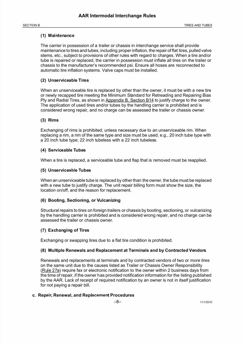
(1) Maintenance
The carrier in possession of a trailer or chassis in interchange service shall providemaintenance to tires and tubes, including proper inflation, the repair of flat tires, pulled valvestems, etc., subject to provisions of other rules with regard to charges. When a tire and/or
tube is repaired or replaced, the carrier in possession must inflate all tires on the trailer or chassis to the manufacturer’s recommended psi. Ensure all hoses are reconnected toautomatic tire inflation systems. Valve caps must be installed.
(2) Unserviceable Tires
When an unserviceable tire is replaced by other than the owner, it must be with a new tireor newly recapped tire meeting the Minimum Standard for Retreading and Repairing BiasPly and Radial Tires, as shown in Appendix B, Section B14 to justify charge to the owner.The application of used tires and/or tubes by the handling carrier is prohibited and isconsidered wrong repair, and no charge can be assessed the trailer or chassis owner.
(3) Rims
Exchanging of rims is prohibited, unless necessary due to an unserviceable rim. Whenreplacing a rim, a rim of the same type and size must be used, e.g., 20 inch tube type witha 20 inch tube type; 22 inch tubeless with a 22 inch tubeless.
(4) Serviceable Tubes
When a tire is replaced, a serviceable tube and flap that is removed must be reapplied.
(5) Unserviceable Tubes
When an unserviceable tube is replaced by other than the owner, the tube must be replacedwith a new tube to justify charge. The unit repair billing form must show the size, thelocation on/off, and the reason for replacement.
(6) Booting, Sectioning, or Vulcanizing
Structural repairs to tires on foreign trailers or chassis by booting, sectioning, or vulcanizingby the handling carrier is prohibited and is considered wrong repair, and no charge can beassessed the trailer or chassis owner.
(7) Exchanging of Tires
Exchanging or swapping tires due to a flat tire condition is prohibited.
(8) Multiple Renewals and Replacement at Terminals and by Contracted Vendors
Renewals and replacements at terminals and by contracted vendors of two or more tireson the same unit due to the causes listed as Trailer or Chassis Owner Responsibility(Rule 27a) require fax or electronic notification to the owner within 2 business days fromthe time of repair, if the owner has provided notification information for the listing publishedby the AAR. Lack of receipt of required notification by an owner is not in itself justificationfor not paying a repair bill.
c. Repair, Renewal, and Replacement Procedures

8/23/2019 AAR Intermodal Interchange Rules
http://slidepdf.com/reader/full/aar-intermodal-interchange-rules 27/224
11/1/2010 –9–
AAR Intermodal Interchange Rules
SECTION BTIRES AND TUBES
(1) Tire Repair Billing Form
The Tire Repair Billing Form to the owner must show the tire size and manufacturer’s DOTtire identification number for each new tire applied or the recapper’s DOT tire identificationnumber for each recapped tire applied to justify charge. The same information must also
be shown for each tire removed, if available. Billing must also show tire location and thereason for replacement to justify charge. All information pertaining to DOT identificationcodes, both on new or recap tires, must follow federal regulations, in accordance with TireIdentification and Recordkeeping Regulation, 49 CFR Part 574 (36 F.R. 1196).
(2) Inspection and Collection of Unserviceable Tires
The inspection and collection of unserviceable tire(s) shall be a matter of mutual agreementbetween involved parties as to procedures.
(3) Retention Period
When tires are removed from a trailer or chassis at an intermodal facility or at an outsiderepair facility authorized by the railroad, the tire must be maintained at the facility for at least7 days or as otherwise agreed. Tire(s) must be marked identifying the trailer or chassisinitial and number, date, wheel position, and circle defect. The Why Made Code and treaddepth must also be indicated.
28. to 40. Vacant

8/23/2019 AAR Intermodal Interchange Rules
http://slidepdf.com/reader/full/aar-intermodal-interchange-rules 28/224 –10– 11/1/2010
AAR Intermodal Interchange Rules
SECTION B TIRES AND TUBES
THIS PAGE LEFT BLANK INTENTIONALLY

8/23/2019 AAR Intermodal Interchange Rules
http://slidepdf.com/reader/full/aar-intermodal-interchange-rules 29/224
11/1/2010 –11–
AAR Intermodal Interchange Rules
SECTION CLANDING GEARS
SECTION C
LANDING GEARS
41. Conditions at Time of Acceptance and in Interchange
The following are conditions at time of acceptance and in interchange:
a. Load Support
The landing gear must be in suitable condition to properly support the trailer or chassis load.
b. Condition and Securement
The landing gear must be properly secured to trailer or chassis, complete as to componentparts, and in satisfactory operating condition.
c. Clearances
The landing gear of the trailer or chassis while loaded on a railcar must clear the car floor andother fixed obstructions at all times by not less than 2 inches, to prevent damage.
42. Maintenance and Operation
a. Maintenance, Repairs, and Lubrication
The carrier in possession of the trailer shall provide good maintenance to the landing gear,including minor repairs and lubrication.
b. Raising Landing Gear
The landing gear must be raised sufficiently above the car floor or ground before movingthe trailer or chassis, to prevent damage.
c. Lowering Landing Gear
The trailer or chassis landing gear must be properly lowered before disconnecting the tractor from the trailer or chassi.
43. to 54. Vacant

8/23/2019 AAR Intermodal Interchange Rules
http://slidepdf.com/reader/full/aar-intermodal-interchange-rules 30/224 –12– 11/1/2010
AAR Intermodal Interchange Rules
SECTION C LANDING GEARS
THIS PAGE LEFT BLANK INTENTIONALLY

8/23/2019 AAR Intermodal Interchange Rules
http://slidepdf.com/reader/full/aar-intermodal-interchange-rules 31/224
11/1/2010 –13–
AAR Intermodal Interchange Rules
SECTION DREFRIGERATION AND HEATING
SECTION D
REFRIGERATION AND HEATING
55. Conditions at Time of Acceptance and in Interchange for Mechanical Units
The following are conditions at time of acceptance and in interchange:
a. Stenciling/Fuel type
Trailers or containers equipped with mechanical units shall be stenciled in letters not less than1 inch high to indicate the type of fuel used to drive the unit and the capacity of the fuel tank.Stenciling shall be located adjacent to the unit or fuel tank filler cap. The type of fuel used for operating the mechanical unit is subject to the restrictions provided in Section A, Rule 17.
b. Satisfactory Operating Condition
At the time of interchange of a loaded trailer or container under heat or refrigeration, themechanical unit shall be in satisfactory operating condition. Where evidence indicates adefective mechanical unit or improper inside air temperature, the trailer or container may berefused in interchange.
c. Sufficient Oil and fuel
At the time of interchange of a loaded trailer or container under heat or refrigeration, themechanical unit shall have sufficient oil and fuel to ensure 24 hours’ continuous operation.
56. Vacant
57. Maintenance
The carrier in possession of the trailer or container shall provide proper maintenance to the heatingand/or refrigeration unit, including any immediate repair necessary to maintain lading protection.The cost of repairs made as a result of such maintenance may be billed against the owner, exceptthat fuel applied is at no expense to the owner. Where Division Sheet or contracts provideotherwise, the provisions of this rule do not apply.
58. Portable Units
Trailer/container equipment with portable units may be refused in interchange service.
59. to 70. Vacant

8/23/2019 AAR Intermodal Interchange Rules
http://slidepdf.com/reader/full/aar-intermodal-interchange-rules 32/224 –14– 11/1/2010
AAR Intermodal Interchange Rules
SECTION D REFRIGERATION AND HEATING
THIS PAGE LEFT BLANK INTENTIONALLY

8/23/2019 AAR Intermodal Interchange Rules
http://slidepdf.com/reader/full/aar-intermodal-interchange-rules 33/224
11/1/2010 –15–
AAR Intermodal Interchange Rules
SECTION E ACCESSORIES AND SPECIAL EQUIPMENT
SECTION E
ACCESSORIES AND SPECIAL EQUIPMENT
71. Removable Items/Stenciling
The name and number of removable items accompanying open top, platform, or flatbed trailersmust be stenciled in not less than 1 inch figures in a suitable location of the trailer (preferably thefront portion of the bulkhead).
Removable items include:
a. Chains, binders, cables and tie-down devices
b. Tarpaulins, including securements
c. Tarpaulin bows
d. Rear header bar (high-side open top)
e. Bulkhead
72. Delivering Carrier Responsibility
The delivering carrier shall be responsible for any removable items listed in Rule 71, and sostenciled on trailer, that are missing when the trailer is offered in interchange.
73. Handling Carrier Responsibility
a. Securement of EquipmentThe proper replacement and securement on the trailer of tarpaulins, tarpaulin bows, rear header bar, side sections, end gates, etc., that were removed to facilitate loading or unloading is theresponsibility of the carrier in possession of the trailer.
b. Tarpaulins and Bows—Loaded Trailers
When a loaded open top trailer is offered in interchange and is equipped with tarpaulins andbows, the tarpaulin and bows must be in their proper position with the tarpaulin spread andsecured.
In the event the lading is of such nature that the tarpaulin and bows cannot be applied, they
must be placed in the proper storage receptacle where the trailer is so equipped or accompanythe load, if possible. If the equipment cannot be forwarded in either manner, provision shouldbe made to ship same to the trailer owner, properly identified, at the expense of the carrier returning the equipment.

8/23/2019 AAR Intermodal Interchange Rules
http://slidepdf.com/reader/full/aar-intermodal-interchange-rules 34/224 –16– 11/1/2010
AAR Intermodal Interchange Rules
SECTION E ACCESSORIES AND SPECIAL EQUIPMENT
c. Equipment—Empty Trailers
When an empty open top or platform type trailer is offered in interchange and is equipped withtarpaulin and bows, side and end gates, etc., the tarpaulin and bows, side and end gates, etc.,must be in proper place and secured on the trailer or placed in the proper storage receptacle
(where the trailer is so equipped) or be secured to the headboard or deck of the trailer.
When side and end gates are in an upright position on the trailer, the bows must also be inproper position, and the tarpaulin must be properly stored.
Chains, binders, cables, and tie-downs devices must not be laced or allowed to hang over rubrails of flatbed trailers.
74. to 80. Vacant
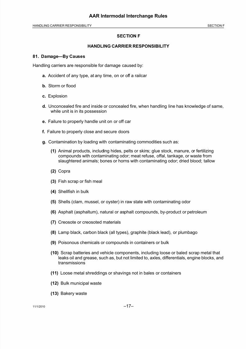
8/23/2019 AAR Intermodal Interchange Rules
http://slidepdf.com/reader/full/aar-intermodal-interchange-rules 35/224
11/1/2010 –17–
AAR Intermodal Interchange Rules
SECTION FHANDLING CARRIER RESPONSIBILITY
SECTION F
HANDLING CARRIER RESPONSIBILITY
81. Damage—By Causes
Handling carriers are responsible for damage caused by:
a. Accident of any type, at any time, on or off a railcar
b. Storm or flood
c. Explosion
d. Unconcealed fire and inside or concealed fire, when handling line has knowledge of same,while unit is in its possession
e. Failure to properly handle unit on or off car
f. Failure to properly close and secure doors
g. Contamination by loading with contaminating commodities such as:
(1) Animal products, including hides, pelts or skins; glue stock, manure, or fertilizingcompounds with contaminating odor; meat refuse, offal, tankage, or waste fromslaughtered animals; bones or horns with contaminating odor; dried blood; tallow
(2) Copra
(3) Fish scrap or fish meal
(4) Shellfish in bulk
(5) Shells (clam, mussel, or oyster) in raw state with contaminating odor
(6) Asphalt (asphaltum), natural or asphalt compounds, by-product or petroleum
(7) Creosote or creosoted materials
(8) Lamp black, carbon black (all types), graphite (black lead), or plumbago
(9) Poisonous chemicals or compounds in containers or bulk
(10) Scrap batteries and vehicle components, including loose or baled scrap metal thatleaks oil and grease, such as, but not limited to, axles, differentials, engine blocks, andtransmissions
(11) Loose metal shreddings or shavings not in bales or containers
(12) Bulk municipal waste
(13) Bakery waste

8/23/2019 AAR Intermodal Interchange Rules
http://slidepdf.com/reader/full/aar-intermodal-interchange-rules 36/224 –18– 11/1/2010
AAR Intermodal Interchange Rules
SECTION F HANDLING CARRIER RESPONSIBILITY
h. Repair and servicing to brakes and brake system components due to accumulation of iceand snow
82. Damage—Evidential
Handling carriers are responsible for damage as follows:
a. Metal door, gate, sheet, post, crossmember, brace, or support cut or torn through thicknessof metal, including such cuts or tears covered by tape, caulk, and/or tar
b. Metal door, gate, sheet, post, crossmember, brace, or support bent, where proper operationor function of unit is impaired, except when caused by deterioration due to corrosion or decay
c. Clean Interior
d. DOT Under Ride Guard missing or bent/cut per Appendix B, Section B15
e. Tire sidewall cut/punctured through one or more plies of fabric
f. Tire shoulder and/or tread cut/punctured through one or more plies of fabric, when such injuryis larger than 1/4 inch. When the tire shoulder and/or tread is punctured through the tire,causing a hole 1/4 inch in diameter or less, the injury must be patched prior to reuse.
g. Damage to tires and tubes as a result of being slid flat. Any tire is considered to be “slid flat”if a flat spot occurs and removes 4/32 inches of tread or rubber (when compared to the re-maining tread). It is not necessary for the tire to have a loss of air.
h. Damage to tires and tubes as a result of being run flat. To prevent run-flat damage, tires
should be inflated as per Appendix B, Section B14.
83. Losses
Handling carriers are responsible for loss as follows:
a. Theft of trailer, container, chassis, or bogie, or known theft of parts thereof
b. Door or gate missing
c. Removable side or section missing
d. Missing tire, tube, or rim
e. Missing assigned equipment, as outlined in Rule 71, that accompanied trailer at time of interchange
f. Missing component parts essential for the operation of mechanical units for refrigeration or heating.
84. Contamination Commodities
a. Loading Restriction

8/23/2019 AAR Intermodal Interchange Rules
http://slidepdf.com/reader/full/aar-intermodal-interchange-rules 37/224
11/1/2010 –19–
AAR Intermodal Interchange Rules
SECTION FHANDLING CARRIER RESPONSIBILITY
Trailers or containers must not be loaded with contaminating commodities unless the trailer or container is stenciled by the owner “Contaminate Loading Only” on the front of the vehicle in notless than 4 inch letters and is identified in the Official Intermodal Equipment Register , or asotherwise specifically authorized by owner.
b. Reporting Contaminating Loadings
Where the handling carrier is not responsible for a contaminating loading, it shall furnishinformation on the unit inspection form to indicate the originating carrier, who shall beresponsible to the owner for reconditioning of the trailer or container.
85. Temporary Repairs
Handling carriers shall be responsible for correction of temporary repairs as outlined in Rule 101b.
86. Damage by Non-AAR Member
a. Railroad-Owned or Leased Units
When a railroad-owned or leased unit is damaged or destroyed while in the possession of anon-AAR member to the Intermodal Interchange Rules, the AAR member delivering the unit tosuch non-AAR member shall be responsible to the owner for damage to or destruction of theunit while in the possession of the non-AAR member.
b. Non-Railroad-Owned or Leased Units
When a non-railroad-owned or leased unit is damaged or destroyed while in the possession of a non-AAR member to the Intermodal Interchange Rules, responsibility and settlement for damage or destruction will be in accordance with individual contract.
87. Vacant

8/23/2019 AAR Intermodal Interchange Rules
http://slidepdf.com/reader/full/aar-intermodal-interchange-rules 38/224 –20– 11/1/2010
AAR Intermodal Interchange Rules
SECTION F HANDLING CARRIER RESPONSIBILITY
THIS PAGE LEFT BLANK INTENTIONALLY
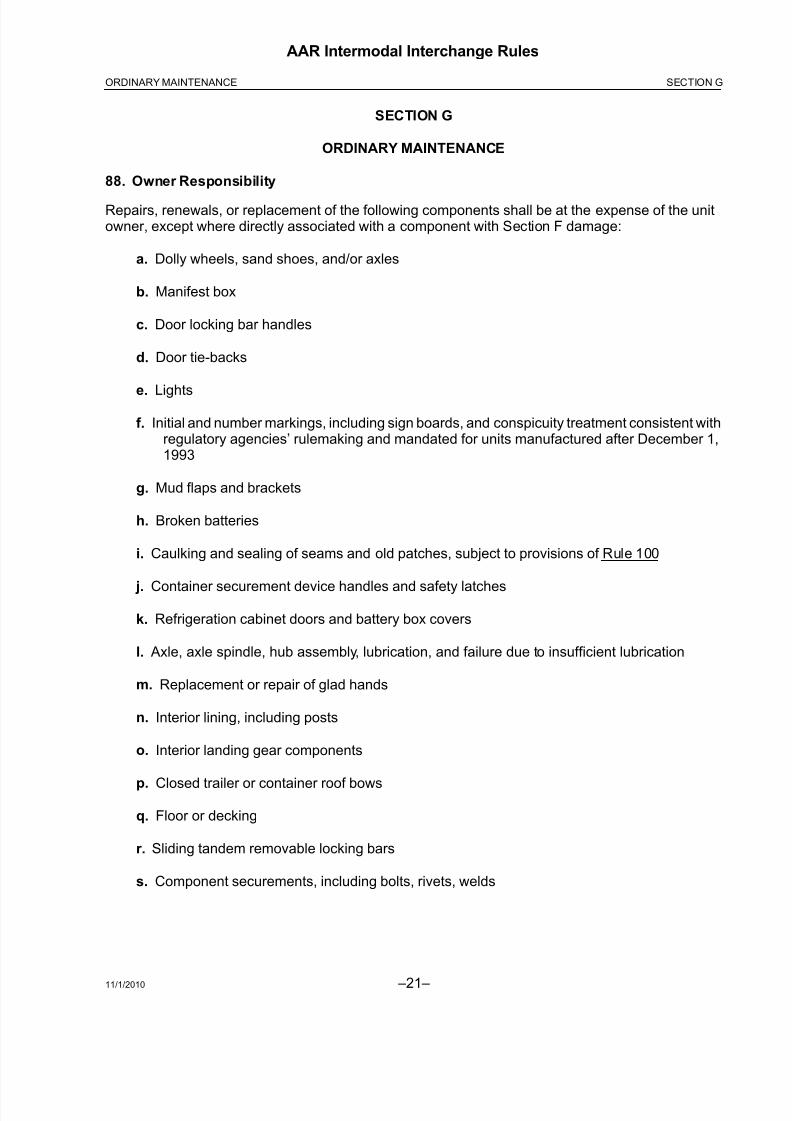
8/23/2019 AAR Intermodal Interchange Rules
http://slidepdf.com/reader/full/aar-intermodal-interchange-rules 39/224
11/1/2010 –21–
AAR Intermodal Interchange Rules
SECTION GORDINARY MAINTENANCE
SECTION G
ORDINARY MAINTENANCE
88. Owner Responsibility
Repairs, renewals, or replacement of the following components shall be at the expense of the unitowner, except where directly associated with a component with Section F damage:
a. Dolly wheels, sand shoes, and/or axles
b. Manifest box
c. Door locking bar handles
d. Door tie-backs
e. Lights
f. Initial and number markings, including sign boards, and conspicuity treatment consistent withregulatory agencies’ rulemaking and mandated for units manufactured after December 1,1993
g. Mud flaps and brackets
h. Broken batteries
i. Caulking and sealing of seams and old patches, subject to provisions of Rule 100
j. Container securement device handles and safety latches
k. Refrigeration cabinet doors and battery box covers
l. Axle, axle spindle, hub assembly, lubrication, and failure due to insufficient lubrication
m. Replacement or repair of glad hands
n. Interior lining, including posts
o. Interior landing gear components
p. Closed trailer or container roof bows
q. Floor or decking
r. Sliding tandem removable locking bars
s. Component securements, including bolts, rivets, welds
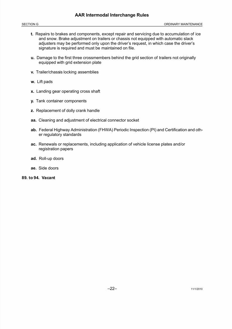
8/23/2019 AAR Intermodal Interchange Rules
http://slidepdf.com/reader/full/aar-intermodal-interchange-rules 40/224 –22– 11/1/2010
AAR Intermodal Interchange Rules
SECTION G ORDINARY MAINTENANCE
t. Repairs to brakes and components, except repair and servicing due to accumulation of iceand snow. Brake adjustment on trailers or chassis not equipped with automatic slackadjusters may be performed only upon the driver’s request, in which case the driver’ssignature is required and must be maintained on file.
u. Damage to the first three crossmembers behind the grid section of trailers not originallyequipped with grid extension plate
v. Trailer/chassis locking assemblies
w. Lift pads
x. Landing gear operating cross shaft
y. Tank container components
z. Replacement of dolly crank handle
aa. Cleaning and adjustment of electrical connector socket
ab. Federal Highway Administration (FHWA) Periodic Inspection (PI) and Certification and oth-er regulatory standards
ac. Renewals or replacements, including application of vehicle license plates and/or registration papers
ad. Roll-up doors
ae. Side doors
89. to 94. Vacant

8/23/2019 AAR Intermodal Interchange Rules
http://slidepdf.com/reader/full/aar-intermodal-interchange-rules 41/224
11/1/2010 –23–
AAR Intermodal Interchange Rules
SECTION HREPAIRS AND BILLING
SECTION H
REPAIRS AND BILLING
95. Detailed Procedures
For more detailed procedures on repairs and billing, refer to Appendix A.
96. Repairs Exceeding $450
When the estimated cost of repairs exceeds $450 or other amount specified by the owner,exclusive of tires and refrigeration unit, repairs shall be handled under the provisions of Section L,Rule 156 or Section M, Rule 165 and Rule 166.
97. Handling Line Responsibility
When a unit damaged in excess of $450 or other amount specified by owner is returned to its owner for repairs, the carrier responsible for the damage will be responsible for those items as listed onForm J-2 or recorded image.
98. Repair Cost Limit
In no case shall the cost of repairs to a unit exceed its depreciated value less salvage, except asprovided in agreements between carriers and handling lines.
99. Standards for Repair
When repairs are made to a unit, the owner’s standard must be maintained, and material appliedmust be of similar quality and type as material removed. Repairs are subject to the procedures of
Appendix B. Repairs, when completed, are subject to acceptance by the unit owner. If the owner’s
standard(s) for the applicable repair or replacement of specific component(s) is stenciled on theunit, such standard must be followed.
100. Safety—Conditioning for Loading
Any unit that requires repairs to render it safe for handling or to condition it for loading, may berepaired subject to provisions of these Intermodal Interchange Rules. However, if repairs are madein order to condition the unit for loading, the repairing company must load the unit before releasingor interchanging it in order to justify the bill for repairs.
101. Repairs Requiring Authorization
a. All repairs to the following trailer components must be performed only by authorization andat the direction of the owner:
(1) Kingpin and/or upper coupler assembly
(2) Anti-skid braking devices
(3) Exterior fiberglass sidewalls
(4) Top and bottom rails, corner posts, stacking posts
(5) Refrigeration trailer or container end doors

8/23/2019 AAR Intermodal Interchange Rules
http://slidepdf.com/reader/full/aar-intermodal-interchange-rules 42/224 –24– 11/1/2010
AAR Intermodal Interchange Rules
SECTION H REPAIRS AND BILLING
(6) Brake adjustment on trailers or chassis equipped with automatic slack adjusters,except as may be required by government regulation. Brake adjustment on trailers or chassis not so equipped may be performed only upon the driver’s request, in whichcase the driver’s signature is required and must be maintained on file.
(7) The repair or replacement of Trailer Under Ride Guards (ICC Bumpers) that arecertified in accordance with FMVSS 223 and FMVSS 224 effective January 26, 1998
b. Units identified with improper repairs by handling line must be handled as follows:
If the estimated cost of correcting the improper repairs exceeds $100, the cost shall be subjectto acceptance by the delivering carrier or carrier responsible for such improper repairs. If thecarrier responsible for improper repairs cannot be determined, authorization must be obtainedfrom the equipment owner to correct improper repairs. Authorization requests must besupported with photographs and proof that improper repair was not performed on the handlingcarrier's line.
102. Citations
The unit owner or lessor shall make full payment on the citation. The rail carrier in possession of therail-controlled unit at the time of the citation may be rebilled by the unit owner or lessee.
103. to 109. Vacant

8/23/2019 AAR Intermodal Interchange Rules
http://slidepdf.com/reader/full/aar-intermodal-interchange-rules 43/224
11/1/2010 –25–
AAR Intermodal Interchange Rules
SECTION I ADJUSTMENT OR TRANSFER
SECTION I
ADJUSTMENT OR TRANSFER OF TRAILERS AND/OR LADING
110. Delivering Carrier Responsibility
a. Compliance with Loading Rules
Lading shall be properly distributed, secured, and blocked, and in compliance with the AAR Intermodal Loading Guide for Products in Closed Trailers and Containers, and the AAR Mechanical Section 7 Rules Governing the Loading of Commodities on Open Top Trailers to BeHandled in Trailer/Container-on-Flat-Car (TOFC/COFC) Service (which includes flat bed andplatform equipment).
b. Adjustment/Transfer of Units and Lading
Adjustment or transfer of units and/or lading shall be the responsibility of the delivering carrier as follows:
(1) Shifted Contents/Improper Loading
When a trailer or container is delivered by rail, street, or highway for interchange andrequires adjustment of lading due to shifted contents or improper loading.
(2) Defective Trailer or Container
When requiring transfer or adjustment of lading due to a defective trailer or container thatcannot be readily repaired.
(3) Defective Car/Attachment
When requiring transfer of unit due to a defective carrying car or attachment that cannot bereadily repaired.
111. Originating Carrier Responsibility
The following shall be the responsibility of originating carrier:
a. Transfer—Clearance Violation
Transfer due to clearance violation as outlined in Section A, Rule 4.
b. Transfer and Delivery—Overload
Transfer due to overload, if in violation of Section A, Rule 5. If a portion of the load must betransferred to another trailer or container, all costs of delivering the second trailer shall be theresponsibility of originating carrier.
c. Damage—Overload
Damage to trailer or container due to overloading, if in violation of Section A, Rule 5.
112. to 119. Vacant

8/23/2019 AAR Intermodal Interchange Rules
http://slidepdf.com/reader/full/aar-intermodal-interchange-rules 44/224 –26– 11/1/2010
AAR Intermodal Interchange Rules
SECTION I ADJUSTMENT OR TRANSFER
THIS PAGE LEFT BLANK INTENTIONALLY

8/23/2019 AAR Intermodal Interchange Rules
http://slidepdf.com/reader/full/aar-intermodal-interchange-rules 45/224
11/1/2010 –27–
AAR Intermodal Interchange Rules
SECTION JFORMS AND REPORTS
SECTION J
FORMS AND REPORTS
120. General Instructions
Forms and/or reports as required by these rules shall be in accord with the following provisions asto form, use, and manner of preparation. Any suitable equivalent form, report, or electronic imagemay be used, provided it embodies the minimum information required.
121. Unit Interchange and Safety Inspection Report, Form J-1
Form J-1, equivalent, or recorded image shall be prepared by an authorized representative eachtime a unit is offered for interchange movement by street or highway. (See Figure 2.)
At locations with electronic camera technology that captures images of equipment and damage, itshall not be a requirement to provide notification of damage at time of interchange. Any invoice for damage to the equipment shall be accompanied by an electronic picture of the actual interchangeof the unit showing damage with a date and time stamp.
122. Unit Damage Responsibility Report, Form J-2
a. Preparation and Use of Form
(1) Damage Form and Distribution
Form J-2 (see Figure 3) shall be prepared by an authorized representative of the handlingcarrier to document damage or loss for which the handling carrier is responsible. The formshall be prepared at the place of interchange and then accompany the bill for repairs to thecarrier responsible.
One copy shall be forwarded to a processor for electronic distribution and billing. One copyshall be retained by the issuing party. Copies shall be forwarded within 48 hours from thetime of preparation. The processor will electronically distribute copies of Form J-2 todelivering and receiving parties.
(2) Recorded Image
A recorded image of the damage, taken at the time and place of interchange, may be usedin lieu of a written Form J-2. This recorded image may be used to document damage or loss for which the handling carrier is responsible.
(3) Interchange with Unrepaired Damage Not Covered by Form
In the event a unit is offered in interchange with unrepaired damage or loss for which thedelivering carrier is responsible and that is not covered by a copy of this form, the receivingcarrier shall obtain from the delivering carrier a copy of Form J-2 described in Rule 122a or a recorded image of the damage.

8/23/2019 AAR Intermodal Interchange Rules
http://slidepdf.com/reader/full/aar-intermodal-interchange-rules 46/224 –28– 11/1/2010
AAR Intermodal Interchange Rules
SECTION J FORMS AND REPORTS
(4) Time Limit for Repair
Damage covered by this report must be repaired within 90 days from date of Form J-2;facilities equipped with automatic gates systems must have damages repaired within 45days of interchange to justify bill for repairs.
(5) Associated Damage
When performing repairs to damaged items noted on Form J-2, it is allowable to repair andbill for the associated damaged item(s) if necessary for a proper repair. Associated itemsmust be indicated by why made code 01 on repair bill.
If the estimate of associated repairs exceeds $250 or another amount specified by theresponsible party, endorsement by the responsible party must be secured prior to repairsbeing made.
Associated damage is damage to adjoining components occurring in the same
incident.
b. Exception to Form
After issuance, this report must not be altered and shall be binding. It is the responsibility theparty taking exception to Form J-2 under provisions of Rule 122a(4), Time Limit for Repair, toprovide equipment movement information to the billing party to substantiate exception.
c. Provision of Rebill Authority
When a unit is returned to its owner, the delivering carrier shall provide the owner with rebillauthority within 48 hours, excluding Saturdays, Sundays, and holidays, from written or electronic notification by the owner to the delivering carrier of damages, unless in dispute.Failure to provide the owner with rebill endorsement authority, unless in dispute, shall constitutea valid acceptance by the delivering carrier of damages as specified on Form J-2 or itsequivalent.
123. Authority for Adjustment or Transfer of Unit or Lading, Form J-3
a. Preparation and Use of Form
Form J-3 (see Figure 5) or electronic equivalent shall be prepared in triplicate by an authorizedrepresentative of the handling carrier when it is necessary to transfer or adjust lading in a trailer,container, or a trailer on a car, and it is the responsibility of the carrier as set forth in Section I,“ Adjustment or Transfer of Trailers and/or Lading,” of these rules.
The original form shall accompany the bill, one copy shall be forwarded to the carrier responsible, and one copy shall be retained by the handling carrier.
b. Expense Responsibility
The expense of adjustment or transfer of unit or lading shall be handled by contract.
8/23/2019 AAR Intermodal Interchange Rules
http://slidepdf.com/reader/full/aar-intermodal-interchange-rules 47/224
11/1/2010 –29–
AAR Intermodal Interchange Rules
SECTION JFORMS AND REPORTS
124. Vacant
125. Authority for Counterbilling, Form J-5
a. Purpose
Form J-5, Counterbilling Authority, shall be used for monetary adjustment between the partiesconcerned. (See Figure 7)
b. Completion of Form
All details in Counterbilling Authority, Form J-5, must be properly filled out.
126. FHWA-PI Certification, Form J-6
Form J-6 (see Figure 8) shall be prepared by a certified FHWA-PI inspector as follows: the originalor an electronic version thereof shall accompany the bill, one copy shall be placed on the trailer or chassis, one copy shall be forwarded to the owner within 30 days after certification, and one copyshall be for the inspector.

8/23/2019 AAR Intermodal Interchange Rules
http://slidepdf.com/reader/full/aar-intermodal-interchange-rules 48/224 –30– 11/1/2010
AAR Intermodal Interchange Rules
SECTION J FORMS AND REPORTS
127. FHWA-PI Certification Acknowledgment, Form J-7
a. Form J-7 (decal) (see Figure 9) shall be applied to the lower right front center (nose) of thetrailer (curb side).
b. Form J-7 (decal) (see Figure 9) shall be applied on chassis on the left side main rail next tothe document holder (viewable when loaded). It shall be at least 6 in. × 4 ½ in. in size.
The decal shall have black letters on a white background. It shall be at least 8½ in. × 8½ in. in size.Its letters shall have the following minimum dimensions:
“AAR FORM J-7”: ½ inch
“FHWA – PI,” “MONTH, YEAR”: 1 inch
Other letters: 5/16 inch
128. AAR Flat File Format
The “J File” allows for the electronic exchange of damage data. Refer to Appendix D for structureand sample.
129. to 135. Vacant

8/23/2019 AAR Intermodal Interchange Rules
http://slidepdf.com/reader/full/aar-intermodal-interchange-rules 49/224
Figure 2 Form J-1 — Unit Interchange and Safety Inspection Form
)RUP-UNIT INTERCHANGE AND SAFETY INSPECTION FORM
Initial__________________ Number________________ Van Container Chassis
Station____________________________________ Date____________________ Time____________
Delivered By_______________________________ Received By_______________________________
Seal No.__________________________________ License No.________________________________
Origin_______________________ Route_______________________ Destination_________________
MARK CLEARLY ALL DAMAGE BY INSPECTION SYMBOL “C” CUT, “B” BENT, “K” BROKEN, “M” MISSING
EXPLAIN DEFECTS:
TIRE CONDITIONS: “C” CUT, “SF” SLID FLAT, “RF” RUN FLAT, “M” MISSING
ROF LOF
RIF LIF
ROC LOC
RIC LIC
ROQ LOQ
RIQ LIQ
RIR LIR
ROR LOR
INSPECTED AND EXCEPTIONS NOTED
DELIVERED BY_________________________________ RECEIVED BY_________________________________
INSPECTED BY_________________________________ INSPECTED BY________________________________

8/23/2019 AAR Intermodal Interchange Rules
http://slidepdf.com/reader/full/aar-intermodal-interchange-rules 50/224

8/23/2019 AAR Intermodal Interchange Rules
http://slidepdf.com/reader/full/aar-intermodal-interchange-rules 51/224
Figure 4 Vacant
THIS PAGE LEFT BLANK INTENTIONALLY
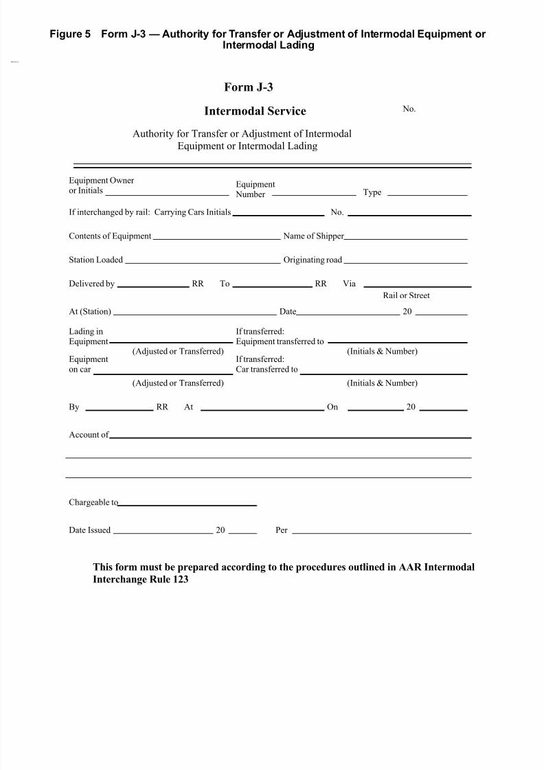
8/23/2019 AAR Intermodal Interchange Rules
http://slidepdf.com/reader/full/aar-intermodal-interchange-rules 52/224
Figure 5 Form J-3 — Authority for Transfer or Adjustment of Intermodal Equipment or Intermodal Lading
)RUP-
,QWHUPRGDO6HUYLFH
Authority for Transfer or Adjustment of IntermodalEquipment or Intermodal Lading
No.
Equipment Owner or Initials
Equipment Number Type
If interchanged by rail: Carrying Cars Initials No.
Contents of Equipment Name of Shipper
Station Loaded Originating road
Delivered by RR To RR Via
Rail or Street
At (Station) Date
Lading inEquipment
If transferred:Equipment transferred to
(Initials & Number)(Adjusted or Transferred)Equipmenton car
If transferred:Car transferred to
(Initials & Number)(Adjusted or Transferred)
By RR At On 20
Account of
Chargeable to
Date Issued Per
20
20
7KLVIRUPPXVWEHSUHSDUHGDFFRUGLQJWRWKHSURFHGXUHVRXWOLQHGLQ$$5,QWHUPRGDO
,QWHUFKDQJH5XOH

8/23/2019 AAR Intermodal Interchange Rules
http://slidepdf.com/reader/full/aar-intermodal-interchange-rules 53/224
Figure 6 Vacant
THIS PAGE LEFT BLANK INTENTIONALLY

8/23/2019 AAR Intermodal Interchange Rules
http://slidepdf.com/reader/full/aar-intermodal-interchange-rules 54/224
Figure 7 Form J-5 — Counterbilling Authority
Form J-5
(Name of Company)
Counterbilling Authority
NO. _______________
DATE: _____________
AMOUNT: __________
ISSUED TO: ________
__________________
ACCOUNT OF:______
__________________
__________________
__________________
NO. ____________
DATE: __________
FILE: ___________
(PREPRINTED ADDRESS)
THIS WILL AUTHORIZE _________________________
TO COUNTERBILL (Name of Company, Preprinted)
$ ____________________________________________
TO ADJUST IN BILL NO.___________,OVERCHARGE
UNDERCHARGE
DOLLARS
__________, ISSUED IN THE AMOUNT OF $ ________
ATTACHED TO BILL_____________________________ THIS AUTHORITY MUST BE
(TITLE)
(Dated)
(State Details Here)

8/23/2019 AAR Intermodal Interchange Rules
http://slidepdf.com/reader/full/aar-intermodal-interchange-rules 55/224
Figure 8 Form J-6 — Federal Highway Administration Periodic Inspection (Sample)
Form J-6 (Sample)
Federal Highway Administration (FHWA) Periodic Inspection (PI)
Trailer Initial Trailer Number
Chassis Initial Chassis Number
Controlling Owner
(According to Equipment Marks)
Vehicle Identification Number (VIN)
(Optional)
Location Inspection Performed
Items Checked OK Defect Repaired Items
Lights
Reflectors
Wiring
Brakes
Air Lines
Kingpin
Tires
Wheels and Rims
Frame and Assembly
Suspension
Axles
Tire Pressure Tire Pressure Tire Pressure Tire Pressure
LOR LOC ROR ROC
LIR LIC RIR RIC
LOQ LOF ROQ ROF
LIQ LIF RIQ RIF
I certify that this unit was inspected on (Month/Year)and meets requirements in accordance with 49 CFR Part 396.
Inspector’s Name (Print)
Inspector’s Signature
Name of Company Performing Repairs
This form or similar form meeting requirements of DOT regulations must be used.

8/23/2019 AAR Intermodal Interchange Rules
http://slidepdf.com/reader/full/aar-intermodal-interchange-rules 56/224
Figure 9 Form J-7 (Sample)
FormJ-7

8/23/2019 AAR Intermodal Interchange Rules
http://slidepdf.com/reader/full/aar-intermodal-interchange-rules 57/224
11/1/2010 –39–
AAR Intermodal Interchange Rules
SECTION KSETTLEMENT OF DISPUTES
SECTION K
SETTLEMENT OF DISPUTES AND REVISION OF RULES
136. Arbiter of Rules
The Intermodal Operations Committee of the AAR shall interpret these Rules and settle disputesthereunder. The Intermodal Operations Committee may initiate, and shall give consideration to,requests for changes to these Rules.
Disputes or questions for interpretation or arbitration arising under these rules between members tosaid rules may be referred to the Intermodal Operations Committee Chairman through its AARrepresentative in one of the following manners and formats.
137. Interpretation of Rules
When formal arbitration of a dispute is not desired and the matter involves interpretation of a Ruleand/or ruling on a specific case, the communication from either of the parties involved shouldcontain all pertinent related information and, where available, copies of letters and/or unit billingrepair forms associated with the particular incident.
138. Formal Arbitration
a. Material to be Submitted
When formal arbitration of a dispute is desired, the contents of the submission to the IntermodalOperations Committee should be as follows:
(1) Both Parties Agree to Arbitration
Where both parties agree to arbitration, three abstracts of all pertinent information, eachconsisting of not more than three typewritten pages, letter size, single spaced, as follows:
1. An agreed statement of facts (signed by both parties)
2. Statement of plaintiff
3. Statement of defendant
(2) One Party Declines to Submit to Arbitration
Where one of the parties declines to submit to arbitration (ex parte), an abstract of all
pertinent information consisting of not more than three typewritten pages, letter size, singlespaced, shall be submitted. Where available, copies of letters and/or unit billing repair forms associated with the particular incident may accompany the abstracts(s).

8/23/2019 AAR Intermodal Interchange Rules
http://slidepdf.com/reader/full/aar-intermodal-interchange-rules 58/224 –40– 11/1/2010
AAR Intermodal Interchange Rules
SECTION K SETTLEMENT OF DISPUTES
b. Procedures
The following principles should be observed in preparing cases for submission to formalarbitration, and should serve as a guide for the proper handling of other disputes:
(1) Roles
(a) In the event of a dispute over responsibility for a charge that is involved in a bill, if the parties cannot reach a conclusion, the carrier against whom the bill is renderedwill be the plaintiff.
(b) In the event of dispute over a question of responsibility on a unit where a bill has notbeen rendered, the carrier having the unit in its possession will be the plaintiff.
(c) In the event of a dispute in connection with a claim made for a unit damageresponsibility report, the carrier instituting such claim will be the plaintiff.
(2) Statements
(a) Agreed Statement of Facts—The plaintiff should prepare the Agreed Statement of Facts, so far as both parties are able to agree. Brief reference should also be madeto the particular question upon which a decision is desired. This statement of facts,in triplicate, should be signed by both parties, one copy to be retained by the plaintiff and the original and one copy to be forwarded to the defendant.
(b) Plaintiff’s Statement—The defendant shall prepare in triplicate a separatestatement outlining his side of the case in concise form, sign same, retain one copy,and forward the original and one copy to the defendant.
(c) Defendant’s Statement—The defendant shall prepare in triplicate a separatestatement outlining his side of the case in concise form, sign same, and forward onecopy to the plaintiff. The defendant shall forward the original statements of bothparties, as well as the Agreed Statement of Facts, to the Intermodal OperationsCommittee AAR representative.
(3) Presence of Principals
Either party involved in the dispute may appear before the Intermodal Operations Commit-tee to answer questions concerning the involved controversy and then be excused. In anydispute where a member of the Intermodal Operations Committee is a party to the dispute,the member will not be present during the discussion and decision on the matter incontroversy, except to the extent permitted in this paragraph.
(4) Finality
The formal arbitration decisions of the Committee shall be final and binding upon the partiesconcerned.
139. Rules Revisions
The Intermodal Operations Committee shall submit, other than editorial changes, proposed rulesrevisions to the subscribers for comment, except those that must be promptly published due togovernment regulation.

8/23/2019 AAR Intermodal Interchange Rules
http://slidepdf.com/reader/full/aar-intermodal-interchange-rules 59/224
11/1/2010 –41–
AAR Intermodal Interchange Rules
SECTION KSETTLEMENT OF DISPUTES
140. to 155. Vacant

8/23/2019 AAR Intermodal Interchange Rules
http://slidepdf.com/reader/full/aar-intermodal-interchange-rules 60/224 –42– 11/1/2010
AAR Intermodal Interchange Rules
SECTION K SETTLEMENT OF DISPUTES
THIS PAGE LEFT BLANK INTENTIONALLY

8/23/2019 AAR Intermodal Interchange Rules
http://slidepdf.com/reader/full/aar-intermodal-interchange-rules 61/224
11/1/2010 –43–
AAR Intermodal Interchange Rules
SECTION LSETTLEMENT FOR DAMAGED/STOLEN UNITS
SECTION L
SETTLEMENT FOR DESTROYED, BADLY DAMAGED, ORSTOLEN UNITS—HANDLING CARRIER RESPONSIBILITY
156. Destroyed, Badly Damaged, or Stolen Units
a. Notification, Depreciated Value, and Disposition
When the estimated cost of complete repairs to a foreign unit for which the handling companyis responsible exceeds $450 or another amount specified by the owner, exclusive of tires, theowner must be advised and requested to furnish disposition of trailer.
The owner, upon request of the handling company, shall furnish disposition at the time of notification, based on the provisions of this section.
In the absence of disposition advice within 10 working days, the handling carrier may apply Unit
Damage Responsibility Report Form J-2, and forward the unit home to the owner, loaded on afreight car or on its own wheels to nearest point of interchange, advising the owner of suchhandling, and assuming all transportation and handling costs, except transportation over theowner’s line.
Upon request, the owner shall also provide a statement showing the depreciated value of theunit.
The time limit for invoicing for destroyed or stolen units shall be no greater than 18 months fromthe date of last interchange.
b. Repair Costs Over Limit
Settlement for destroyed, badly damaged, or stolen unit shall be determined as provided inagreements between owners and handling lines.
If it is estimated by the handling carrier that the cost of complete repairs will exceed thedepreciated value less salvage, the matter shall be handled as prescribed by agreementsbetween the handling carrier and owner.
In the absence of an agreement between the owner and the handling line, the depreciated valueless salvage shall be calculated using Table 1 below.
Equipment is assumed to have a useful life of 15 years and a residual value equal to 10% of the Original Purchase Price.
Depreciated Value = Original Purchase Price multiplied by the Factor listed below for number of months from Build Date to Loss Date. If the Original Purchase Price is not available, the lastavailable Purchase Price should be multiplied by the Factor listed below for the number of months from Build Date to Loss Date.
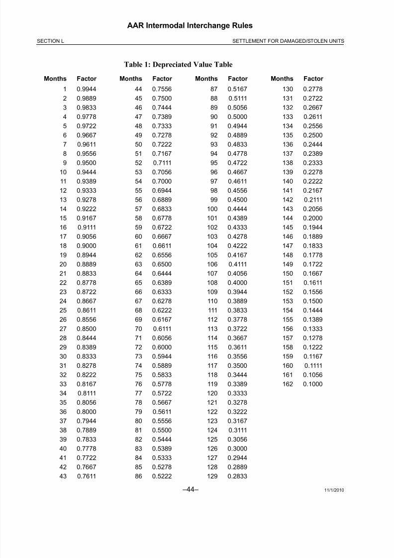
8/23/2019 AAR Intermodal Interchange Rules
http://slidepdf.com/reader/full/aar-intermodal-interchange-rules 62/224 –44– 11/1/2010
AAR Intermodal Interchange Rules
SECTION L SETTLEMENT FOR DAMAGED/STOLEN UNITS
Table 1: Depreciated Value Table
Months Factor Months Factor Months Factor Months Factor
1 0.9944 44 0.7556 87 0.5167 130 0.2778
2 0.9889 45 0.7500 88 0.5111 131 0.27223 0.9833 46 0.7444 89 0.5056 132 0.2667
4 0.9778 47 0.7389 90 0.5000 133 0.2611
5 0.9722 48 0.7333 91 0.4944 134 0.2556
6 0.9667 49 0.7278 92 0.4889 135 0.2500
7 0.9611 50 0.7222 93 0.4833 136 0.2444
8 0.9556 51 0.7167 94 0.4778 137 0.2389
9 0.9500 52 0.7111 95 0.4722 138 0.2333
10 0.9444 53 0.7056 96 0.4667 139 0.2278
11 0.9389 54 0.7000 97 0.4611 140 0.2222
12 0.9333 55 0.6944 98 0.4556 141 0.2167
13 0.9278 56 0.6889 99 0.4500 142 0.2111
14 0.9222 57 0.6833 100 0.4444 143 0.2056
15 0.9167 58 0.6778 101 0.4389 144 0.2000
16 0.9111 59 0.6722 102 0.4333 145 0.1944
17 0.9056 60 0.6667 103 0.4278 146 0.1889
18 0.9000 61 0.6611 104 0.4222 147 0.1833
19 0.8944 62 0.6556 105 0.4167 148 0.1778
20 0.8889 63 0.6500 106 0.4111 149 0.1722
21 0.8833 64 0.6444 107 0.4056 150 0.1667
22 0.8778 65 0.6389 108 0.4000 151 0.1611
23 0.8722 66 0.6333 109 0.3944 152 0.155624 0.8667 67 0.6278 110 0.3889 153 0.1500
25 0.8611 68 0.6222 111 0.3833 154 0.1444
26 0.8556 69 0.6167 112 0.3778 155 0.1389
27 0.8500 70 0.6111 113 0.3722 156 0.1333
28 0.8444 71 0.6056 114 0.3667 157 0.1278
29 0.8389 72 0.6000 115 0.3611 158 0.1222
30 0.8333 73 0.5944 116 0.3556 159 0.1167
31 0.8278 74 0.5889 117 0.3500 160 0.1111
32 0.8222 75 0.5833 118 0.3444 161 0.1056
33 0.8167 76 0.5778 119 0.3389 162 0.1000
34 0.8111 77 0.5722 120 0.3333
35 0.8056 78 0.5667 121 0.3278
36 0.8000 79 0.5611 122 0.3222
37 0.7944 80 0.5556 123 0.3167
38 0.7889 81 0.5500 124 0.3111
39 0.7833 82 0.5444 125 0.3056
40 0.7778 83 0.5389 126 0.3000
41 0.7722 84 0.5333 127 0.2944
42 0.7667 85 0.5278 128 0.2889
43 0.7611 86 0.5222 129 0.2833

8/23/2019 AAR Intermodal Interchange Rules
http://slidepdf.com/reader/full/aar-intermodal-interchange-rules 63/224
11/1/2010 –45–
AAR Intermodal Interchange Rules
SECTION LSETTLEMENT FOR DAMAGED/STOLEN UNITS
c. Salvage Value
Salvage value shall be determined as provided in agreements between the owner and handlingline. In the absence of an agreement between the owner and the handling line establishing sal-vage value, salvage value shall be set at zero dollars.
157. Handling Line Repair
If it is estimated by the handling line that damage is less than the depreciated value less salvage, itmay make complete repairs of $450 (or other amount specified by owner) or less, exclusive of tires,at its own expense, and return the unit to service.
158. Units Requested Home for Repairs
If the owner requests that a unit be returned home for repairs, it shall be so handled, even if thehandling carrier is in a position to, and desires to, make such repairs. However, in such case, theowner shall pay all transportation costs incurred on other than the handling carrier’s lines and shallassume handling costs of the damaging line, not to exceed $200. Handling lines must not
unnecessarily cut up badly damaged trailers to facilitate handling.
159. Equipment Types
Equipment types are defined as follows:
a. Van
A closed unit with fixed sides and end, fixed or sliding metal roof, end doors, with or without sidedoors, and non-insulated.
b. Insulated Van
Same as Rule 159a, Van, but with insulated sides and roof. May or may not have floor insulation.
c. Open Top
A trailer without roof and with fixed sides and front end. May have end doors or gates or remov-able rear end.
d. Platform
A trailer without roof and with removable side panels, racks, or stakes. May have fixed or removable front and/or rear end.
e. Flat Bed
A trailer without roof and with floor only, and without fixed or removable sides, racks, or panels.May have fixed or removable front and/or rear end.
f. Extendable
A trailer with full or partial floor supports or modified supports that may be extended to handleover-dimensional length loads or loads longer than the normal length of that trailer.
g. Reefer/Heater

8/23/2019 AAR Intermodal Interchange Rules
http://slidepdf.com/reader/full/aar-intermodal-interchange-rules 64/224 –46– 11/1/2010
AAR Intermodal Interchange Rules
SECTION L SETTLEMENT FOR DAMAGED/STOLEN UNITS
A closed trailer similar to Rule 159a, Van, but insulted in sides, roof, floor, and all doors. Mayhave front, side, and/or rear doors, or any combination of same. It is permanently equipped witha mechanical unit or other means for providing refrigeration and/or heat.
h. Other
Other types of trailers, including stock, auto transport, bulk loader, and tank.
i. Container
Any of the above types a. through h. that are not quipped with wheels or landing gear.
j. Chassis
An underframe equipped with wheels, landing gear, and kingpin assembly for handling of containers. May be single or multiple axle.

8/23/2019 AAR Intermodal Interchange Rules
http://slidepdf.com/reader/full/aar-intermodal-interchange-rules 65/224
11/1/2010 –47–
AAR Intermodal Interchange Rules
SECTION LSETTLEMENT FOR DAMAGED/STOLEN UNITS
k. Extendable Chassis
A chassis with adjustable main rails to accommodate varying container lengths.
l. Bogie
A wheel assembly, either single or multiple axle.
m. Axle Assemblies
Axle assemblies under trailers are designated as a single, tandem, triple, or quad, dependingon whether one, two, three, or four axles are employed.
n. Wheel Assemblies
Wheel assemblies on axles are designated as single or dual, with single referring to one wheelon each end of the same axle, and dual referring to two wheels on each end of the same axle.
o. Rail-Compatible Trailer
A trailer that can move in hybrid highway/rail service without requiring a carrying car.
p. Tank Containers
A cylindrical structure contained within a rectangular frame of standardized dimensions quicklytransferable as a complete module between a number of modes of transportation.
q. Tank Trailer
A cylindrical s tructure permanently affixed to wheels.
r. Genset
Container or chassis equipped with generator power unit.

8/23/2019 AAR Intermodal Interchange Rules
http://slidepdf.com/reader/full/aar-intermodal-interchange-rules 66/224 –48– 11/1/2010
AAR Intermodal Interchange Rules
SECTION L SETTLEMENT FOR DAMAGED/STOLEN UNITS
Figure 10 Tank Container
160. to 164. Vacant
Jacket End Frame
Catwalk
Ladder
Light Bar
ICC Bumper
Hose Holder Tubes
License Plate
Discharge Valve and
Dust Cap
Mud Flap
Tail Lights
Placard Holder
Temp. Gauge
Data Plate
End Frame
Banding
Outer Jacket
Drain Tube
Decals
Placard Holder
Document Tube
Rear Fenders
Tires and RimsBolster and Twist Lock
Registration HolderDolly Legs
Front Fenders
Splash Guards
Placard Holder
Outer Jacket

8/23/2019 AAR Intermodal Interchange Rules
http://slidepdf.com/reader/full/aar-intermodal-interchange-rules 67/224
11/1/2010 –49–
AAR Intermodal Interchange Rules
SECTION MSETTLEMENT FOR DEFECTIVE UNITS
SECTION M
SETTLEMENT FOR DEFECTIVE UNITS—OWNER’S RESPONSIBILITY
165. Notification
When a foreign unit has owner defects and the estimate of repairs exceeds $450 or another amountspecified by the owner (exclusive of tires and reefer/heater repairs described in Section B andSection D of these Rules), the owner must be notified. Notification shall include the major defectsand the estimated cost of repairs.
166. Disposition
The owner must furnish disposition within 10 working days of the date of notification.
a. Return Home
If the owner elects to have the unit returned home, the owner must reimburse the handlingcarrier the actual cost of loading and assume the freight charges over intermediate lines.
(1) Dispute
If the owner elects to have the handling carrier return the unit, and upon return of the unitthere is a dispute over responsibility, the handling carrier must be given an opportunity for a joint inspection.
b. Disposal
If the owner elects to have the handling carrier dispose of the unit, the handling carrier shall sellthe unit, allowing the amount of the sale to the owner, less the handling carrier’s expense to
dispose of the unit.
167. to 170. Vacant
8/23/2019 AAR Intermodal Interchange Rules
http://slidepdf.com/reader/full/aar-intermodal-interchange-rules 68/224 –50– 11/1/2010
AAR Intermodal Interchange Rules
SECTION M SETTLEMENT FOR DEFECTIVE UNITS
THIS PAGE LEFT BLANK INTENTIONALLY

8/23/2019 AAR Intermodal Interchange Rules
http://slidepdf.com/reader/full/aar-intermodal-interchange-rules 69/224
11/1/2010 –51–
AAR Intermodal Interchange Rules
SECTION NLOCATIONS, MARKINGS, AND AEI
SECTION N
LOCATIONS, MARKINGS, AND AEI
171. Location Designations
For uniformity in reporting location of unit parts in connection with inspection or repairs, thefollowing will govern. Such location designations shall be shown on all repair bills, forms, or reportssubmitted where location information is involved.
a. Front/Rear
The end of the unit to which the tractor power unit is attached shall be known as the front end,and the opposite end shall be known as the rear end.
b. Sides and Top
Sides and top of units are designated as front, center, and rear depending on the type of equipment. For a van or chassis, the dolly legs forward is the front (LSF, RSF, TF), the dolly legsto the tires is the center (LSC, RSC, TC), and the tires to the back is the rear (LSR, RSR, TR).For a container with stacking posts, the front stacking post forward is the front (LSF, RSF, TF),between the stacking posts is the center (LSC, RSC, TC), and the rear stacking post to the backis the rear (LSR, RSR, TR). For 20 ft and 40 ft containers, the sides and top are designated ascenter (LSC, RSC, TC).
c. Tires and Axles
Facing the rear end of the unit, the side to the right shall be known as the right side, and wheels,tires, rims, etc., shall be known as right outside rear (ROR), right inside rear (RIR), right outsidequad (ROQ), right inside quad (RIQ), right outside center (ROC), right inside center (RIC), right
outside front (ROF), and right inside front (RIF).
Similarly, the side to the left shall be known as the left side, and locations shall be known as leftoutside rear (LOR), left inside rear (LIR), left outside quad (LOQ), left inside quad (LIQ), leftoutside center (LOC), left inside center (LIC), left outside front (LOF), and left inside front (LIF).
If only a single axle assembly is involved, it shall be considered as "rear," and if a triple axleassembly is involved, the designations shall be "front," "center," and "rear." If a quad axleassembly is involved, the designations shall be "front," "center," "quad," and "rear." If singlewheels are involved instead of dual wheels, single wheels shall be designated as "outside."
8/23/2019 AAR Intermodal Interchange Rules
http://slidepdf.com/reader/full/aar-intermodal-interchange-rules 70/224 –52– 11/1/2010
AAR Intermodal Interchange Rules
SECTION N LOCATIONS, MARKINGS, AND AEI
172. Stenciling—Weight, Height, Capacity
All trailer, container, and chassis equipment used in interchange service must carry stenciling,preferably on the lower portion of the left side, near the front end of the unit, showing the emptyweight and height of the unit, using not less than 2 inch letters and figures. In addition to the empty
weight, trailers and containers handling bulk liquid commodities must carry stenciling to indicatecapacity in U.S. gallons.
a. Alteration of Stencils
The empty weight of the trailer or container or its capacity in U.S. gallons may not be altered or applied to the trailer or container except by the owner or lessee of the trailer or container.
b. Included in Empty Weight
Only such removable items that are a permanent part of the trailer, including the fullcomplement of items stenciled on the nose of the trailer in accordance with Section E,
Accessories and Special Equipment, and that accompany the trailer at all times shall be
included in stenciled empty weight.

8/23/2019 AAR Intermodal Interchange Rules
http://slidepdf.com/reader/full/aar-intermodal-interchange-rules 71/224
11/1/2010 –53–
AAR Intermodal Interchange Rules
SECTION NLOCATIONS, MARKINGS, AND AEI
Figure 11 Quad Axle Diagram
FRONT
FRONT AXLE
ROF
LIC = LEFT
INSIDE CENTER
ROC = RIGHT OUTSIDE
CENTER
CTR
ROQ = RIGHT OUTSIDE
QUAD
QUAD
LIQ = LEFT INSIDE
QUAD
LOR
REAR AXLE
REAR

8/23/2019 AAR Intermodal Interchange Rules
http://slidepdf.com/reader/full/aar-intermodal-interchange-rules 72/224 –54– 11/1/2010
AAR Intermodal Interchange Rules
SECTION N LOCATIONS, MARKINGS, AND AEI
Figure 12 Tri- and Double-Axle Diagram
FRONT
RIF
ROF
FRONT
RIC
ROCCTR
REAR
LOFLOR
LIR FRONT
REAR
RIR
REAR

8/23/2019 AAR Intermodal Interchange Rules
http://slidepdf.com/reader/full/aar-intermodal-interchange-rules 73/224
11/1/2010 –55–
AAR Intermodal Interchange Rules
SECTION NLOCATIONS, MARKINGS, AND AEI
Figure 13 Axle Diagram (Side)
FrontQuad
Rear Center
Center
Rear Front
Front
Rear

8/23/2019 AAR Intermodal Interchange Rules
http://slidepdf.com/reader/full/aar-intermodal-interchange-rules 74/224 –56– 11/1/2010
AAR Intermodal Interchange Rules
SECTION N LOCATIONS, MARKINGS, AND AEI
173. Reporting Marks and Numbers
To ensure readability of lettering or marking of units, the following shall govern:
a. Trailers or Containers
The assigned reporting marks of the owner or lessee and the trailer or container number mustbe applied to the trailer or container in accordance with The Official Intermodal Equipment Reg-ister , Code of Trailer and Container Service Rules, Section 3, “Reporting Marks and NumberingSystem.” Assigned reporting marks and numbers shall be not less than 6 inches in height oneach side of the trailer or container, and not less than 6 inches in height on the front and rear of the trailer or container.
b. Bogies and Chassis
Bogies or chassis not attached to a container shall have the name or initials of the owner or lessee and the number of the unit applied at one or more locations on the unit, using not lessthan 3 inch letters and figures. A metal ownership plate showing this information, securely
attached to the frame of the unit, is acceptable.
c. Non-Satisfactory Markings
Except as provided in paragraph e. of this rule, paper, cardboard, or similar material that ispasted, glued, or taped to the exterior of the unit or to sign boards attached to the unit to indicateidentification markings for reporting purposes, is not proper or satisfactory marking under thisrule.
d. Short Term Leasing
In the event a unit is operated under a short term leasing arrangement, such as one called “one
trip leasing,” or any other leasing arrangement not exceeding 10 days duration, and the lesseedesires that the unit carry the lessee’s identification markings for reporting purposes, suchmarkings need not comply with provisions of paragraph c. of this rule.
e. Change in Status
When a change occurs in either ownership or lessee status and it is desired or becomesnecessary to change identification markings used for reporting purposes, previous identificationmarkings and placards and/or stencil markings used for reporting purposes must be removedor obliterated.
174. Hazardous Placards
To ensure visibility of hazardous placards applied to containers, the side placards must be locatednot less than 18 inches from the top of the container and not less than 60 inches from the ends of the container.

8/23/2019 AAR Intermodal Interchange Rules
http://slidepdf.com/reader/full/aar-intermodal-interchange-rules 75/224
11/1/2010 –57–
AAR Intermodal Interchange Rules
SECTION NLOCATIONS, MARKINGS, AND AEI
175. Automatic Equipment Identification
To ensure the uniformity and readability of Automatic Equipment Identification (AEI) tags, thefollowing will govern:
a. AEI tags should conform, both in format and placement on the equipment, to the Manual of Standards and Recommended Procedures, Section K, Standard S-918, “Standard for
Automatic Equipment Identification.”
b. Non-standard tags must indicate that the tag is non-standard by the use of “111111”in the Data Format Code field, bits 118-123.
176. to 179. Vacant
8/23/2019 AAR Intermodal Interchange Rules
http://slidepdf.com/reader/full/aar-intermodal-interchange-rules 76/224 –58– 11/1/2010
AAR Intermodal Interchange Rules
SECTION N LOCATIONS, MARKINGS, AND AEI
THIS PAGE LEFT BLANK INTENTIONALLY

8/23/2019 AAR Intermodal Interchange Rules
http://slidepdf.com/reader/full/aar-intermodal-interchange-rules 77/224
11/1/2010 –59–
AAR Intermodal Interchange Rules
SECTION OCONDITIONS OF ACCEPTANCE
SECTION O
CONDITIONS OF ACCEPTANCE
180. Vacant
181. Acceptance of Rules
Acceptance or rejection of this Code of Rules by AAR member railroads must be as a whole.However, AAR member railroads may, by mutual agreement, waive or alter any of these rules asbetween themselves.

8/23/2019 AAR Intermodal Interchange Rules
http://slidepdf.com/reader/full/aar-intermodal-interchange-rules 78/224 –60– 11/1/2010
AAR Intermodal Interchange Rules
SECTION O CONDITIONS OF ACCEPTANCE
THIS PAGE LEFT BLANK INTENTIONALLY

8/23/2019 AAR Intermodal Interchange Rules
http://slidepdf.com/reader/full/aar-intermodal-interchange-rules 79/224
11/1/2010 –61–
AAR Intermodal Interchange Rules
SECTION PSUBSCRIPTION TO RULES
SECTION P
SUBSCRIPTION TO THE INTERMODAL INTERCHANGE RULES
182. Notification
A subscriber to the Intermodal Interchange Rules, by registering, will receive notification of updatesto the Intermodal Interchange Rules.
183. Subscription
Any corporation, partnership, individual, railroad, railroad subsidiary motor carrier, leasing company,forwarding company, shipper, shipper association, motor common carrier, or water carrier engagedin intermodal service may subscribe to the Intermodal Interchange Rules by registering as an “AARIntermodal Interchange Rules Subscriber” on the AAR Web site (www.aar.com).
184. Availability
The Intermodal Interchange Rules are available for viewing or printing at no cost on the AAR Website (www.aar.com). A printed copy can be purchased through the AAR.

8/23/2019 AAR Intermodal Interchange Rules
http://slidepdf.com/reader/full/aar-intermodal-interchange-rules 80/224 –62– 11/1/2010
AAR Intermodal Interchange Rules
SECTION P SUBSCRIPTION TO RULES
THIS PAGE LEFT BLANK INTENTIONALLY

8/23/2019 AAR Intermodal Interchange Rules
http://slidepdf.com/reader/full/aar-intermodal-interchange-rules 81/224
11/1/2010 –63–
AAR Intermodal Interchange Rules
SECTION QPROPOSED CHANGES TO RULES
SECTION Q
PROPOSED CHANGES TO AAR INTERMODAL INTERCHANGE RULES
185. Procedure for Proposing Changes
a. Proposed changes are made to the AAR through their Web site (www.aar.com).
b. All proposed changes are brought before the AAR Intermodal Operations Committee (IOC)for review, discussion, and voting for inclusion or non-inclusion in the AAR Intermodal Interchange Rules.
c. In the event that the IOC determines that it is necessary to distribute a proposed rule changeto subscribers for comment, the IOC will review any comments received and make a finalvote for inclusion or non-inclusion in the AAR Intermodal Interchange Rules.
d. All changes that receive a final vote for inclusion in the AAR Intermodal Interchange Rules
will be provided to the AAR Director—Business Services. AAR will be responsible for publication of a complete document with an updated effective date made available inelectronic format on the AAR Web site (www.aar.com).
e. Upon update of the AAR Intermodal Interchange Rules, all subscribers will be notified viaemail that the new version is available in electronic format on the AAR Web site(www.aar.com).

8/23/2019 AAR Intermodal Interchange Rules
http://slidepdf.com/reader/full/aar-intermodal-interchange-rules 82/224 –64– 11/1/2010
AAR Intermodal Interchange Rules
SECTION Q PROPOSED CHANGES TO RULES
THIS PAGE LEFT BLANK INTENTIONALLY
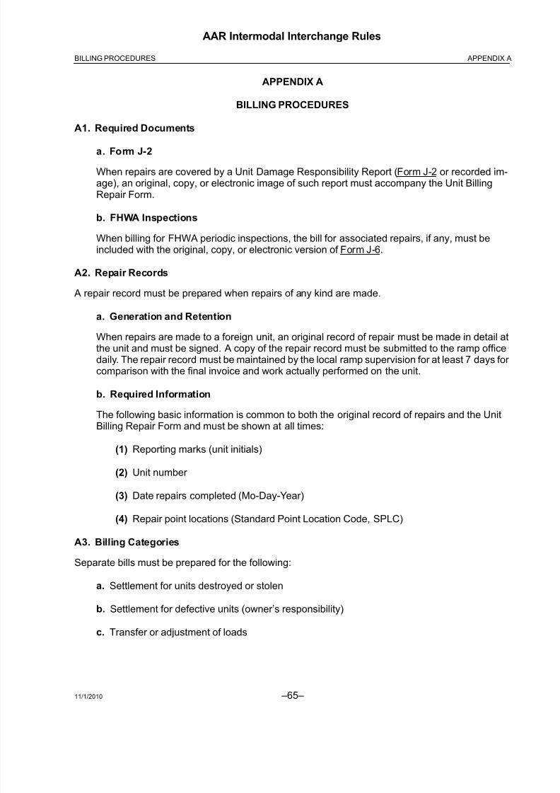
8/23/2019 AAR Intermodal Interchange Rules
http://slidepdf.com/reader/full/aar-intermodal-interchange-rules 83/224
11/1/2010 –65–
AAR Intermodal Interchange Rules
APPENDIX ABILLING PROCEDURES
APPENDIX A
BILLING PROCEDURES
A1. Required Documents
a. Form J-2
When repairs are covered by a Unit Damage Responsibility Report (Form J-2 or recorded im-age), an original, copy, or electronic image of such report must accompany the Unit BillingRepair Form.
b. FHWA Inspections
When billing for FHWA periodic inspections, the bill for associated repairs, if any, must beincluded with the original, copy, or electronic version of Form J-6.
A2. Repair Records A repair record must be prepared when repairs of any kind are made.
a. Generation and Retention
When repairs are made to a foreign unit, an original record of repair must be made in detail atthe unit and must be signed. A copy of the repair record must be submitted to the ramp officedaily. The repair record must be maintained by the local ramp supervision for at least 7 days for comparison with the final invoice and work actually performed on the unit.
b. Required Information
The following basic information is common to both the original record of repairs and the UnitBilling Repair Form and must be shown at all times:
(1) Reporting marks (unit initials)
(2) Unit number
(3) Date repairs completed (Mo-Day-Year)
(4) Repair point locations (Standard Point Location Code, SPLC)
A3. Billing Categories
Separate bills must be prepared for the following:
a. Settlement for units destroyed or stolen
b. Settlement for defective units (owner’s responsibility)
c. Transfer or adjustment of loads

8/23/2019 AAR Intermodal Interchange Rules
http://slidepdf.com/reader/full/aar-intermodal-interchange-rules 84/224 –66– 11/1/2010
AAR Intermodal Interchange Rules
APPENDIX A BILLING PROCEDURES
A4. Billing Formats
Unit repair billing must be submitted in mechanized billing per Rule A5
A5. Mechanized Billing
Mechanized billing must:
a. Itemize all repairs
b. Include all repairs billed
c. When produced, be printed on standard letter size (8½ in. × 11 in.) stock, with only one unitbill per sheet. Alternatively, as provided by agreement between the billing and responsibleparties, billing may be performed through electronic submission, tape submission, or asotherwise agreed upon.
d. Required Information:
(1) Name of billing company
(2) Name of company performing repairs, if other than billing company
(3) Unit initial and number
(a) If container and chassis are mated, initial and number of mate must be shown. If repairs are performed on both units of a mated container and chassis, a separatebilling sheet must be prepared for each unit.
(4) Geographic location (SPLC) of repair
(5) Date of repair
(6) Form J-2/Form J-1/recorded image bill road/company, if applicable
(7) Location of repair on unit
(8) Quantity applied.
(9) Condition Code
(10) Job Code. If Job Codes other than suggested codes listed in Appendix F are used,
they must be furnished to the party receiving the bill.
(11) Description of repairs made, which must be shown with no more than 35 characters
(12) Responsibility Code
(13) Why Made Code
(14) Labor and material charges, shown separately
(15) Overhead charges, if any, shown separately

8/23/2019 AAR Intermodal Interchange Rules
http://slidepdf.com/reader/full/aar-intermodal-interchange-rules 85/224
11/1/2010 –67–
AAR Intermodal Interchange Rules
APPENDIX ABILLING PROCEDURES
(16) Column totals for labor and material
(17) Total charges billed
(18) When the total amount billed exceeds $450 (or other amount specified by owner), unit
built date
(19) Labor shown to the nearest 1/10th hour
(20) Taxes, where applicable
e. When billed on authority of Form J-2/Form J-1/recorded image, include either the originalJ-2/J-1/recorded image or a mechanized facsimile thereof, and Form J-6.
f. Have the support data used to generate mechanized bill retained and made available for inspection and/or audit no less than 1 year from the date of billing, unless otherwiseprovided in separate agreements.
A6. Vacant
A7. Exceptions
When exceptions are taken to a Unit Billing Repair Form, the entire form will be rejected.
A8. No Bills
A record of all repairs performed and not billed to the owner must be included in the monthly billing.
a. Submit the original bill or workorder, or a copy of the original bill or workorder.
b. Submit computer bill or facsimile.
c. Documentation must indicate “No Bill” or “No Charge.”
d. Documentation shall be included with monthly statement or as a separate attachment, butclearly grouped as “No Bills.”
e. Every “No Bill” repair should be forwarded to the owner, unless covered by private contract.

8/23/2019 AAR Intermodal Interchange Rules
http://slidepdf.com/reader/full/aar-intermodal-interchange-rules 86/224 –68– 11/1/2010
AAR Intermodal Interchange Rules
APPENDIX A BILLING PROCEDURES
A9. Handling of Bills
Bills for repairs to equipment covered by these Rules shall be handled as follows:
a. Calculation Date of Charges
Charges must be calculated as of the date of repairs.
b. Owner Responsibility
Charges for all repairs for which the owner is responsible shall be billed against the owner. Inrendering such bill, the equipment involved shall be treated as belonging to the company or individual whose name or initial it bears. Where the unit bears no such identification, itsownership shall be determined by other means.
c. J-2 Repairs
Charges for repairs authorized by the Unit Damage Responsibility Report, Form J-2 or recorded
image, shall be billed against the company shown thereon. The original Form J-2/recorded im-age or a copy thereof shall accompany the billing.
d. Consolidation of Charges
A separate Unit Billing Repair Form and bill shall be submitted for repairs to individual units of equipment, and all charges for repairs shall be consolidated against any one company into oneseparate statement, listing supporting invoices by unit number and amount, each calendar month. An index of billing forms with unit numbers and amounts billed each unit shall be locateddirectly behind the cover sheet of the bill.
e. Time Limits
All bills should be rendered promptly. Bills rendered after 75 days from the date of repairs maybe declined. Where counterbilling is involved, the counterbilling carrier shall be allowed anadditional 30 days to render the bill.
f. Corrections/Counterbilling
(1) No bill shall be returned for correction on account of incorrect unit numbers or reportingmarks, but shall be passed for payment at once, and the alleged error brought to theattention of the company rendering same, no later than 90 days after first receipt of thebill.
(2) To effect economies in the cost of handling bills for unit repairs, it is suggested that
checking for unit numbers and location be eliminated where the total charge per unit isnot more than $5, because it is usually found that corrected numbers are furnished or locations verified.
(3) The billing company shall furnish correct unit reference or shall issue within 90 dayscounterbilling authority. If it is alleged that the unit was not on the repairing road on thedate claimed, the unit owner must show the location of the unit on such date.

8/23/2019 AAR Intermodal Interchange Rules
http://slidepdf.com/reader/full/aar-intermodal-interchange-rules 87/224
11/1/2010 –69–
AAR Intermodal Interchange Rules
APPENDIX ABILLING PROCEDURES
(4) It is suggested that no bills shall be returned for correction on account of other error or questionable charges unless the net amount involved is at least $5 and exceeds 10%of the total amount of bill, but shall be passed for payment at once. Requests for depreciated value statements are for informational purposes and are not to be used toachieve 10% of a bill. All alleged errors must be brought to the attention of the billing
company no later than 60 days after first receipt of the bill; otherwise, the bill is consid-ered valid.
The billing company must furnish proper explanation, shall adjust billing, or shall issuecounterbilling authority within 60 days; otherwise the exceptions are considered valid.
When the net overcharge or undercharge is less than $5, counterbilling authorityshould not be issued and billing repair forms returned. If objections to bill (except for incorrect unit numbers or reporting marks) do not amount to $5 in aggregate, noexception shall be taken, but bill shall be passed for payment as rendered. In any case,however, if an entire bill is improperly rendered, it may be returned, regardless of amount.
Any bill with exceptions may be paid short with a letter sent to the billing subscriber,stating bill number, equipment number(s), and an explanation of the exception(s).
(5) Undercharges shall be called to the attention of the billing company and be similarlyadjusted.
(6) When bills are returned for correction, all Forms J-2 and Billing Repair Forms, exceptthose in question, must be retained by the company against which the bill has beenrendered.
(7) Billing Repair Forms returned for correction or on account of exceptions must not be
defaced in any manner on the face of the form.
(8) Billing Repair Forms returned for adjustment of exceptions should be marked toindicate the bill number of the billing carrier and reference the date of the bill in whichthe charge was included, or the bill number should appear on correspondence inconnection with exceptions taken.
(9) When a bill contains charges from an independent vendor and/or contract shop and theinvoice contains items not chargeable to the owner, the invoice must be adjusted todelete those items not chargeable to the owner.
g. Lost Bills
When a bill, including its Billing Repair Forms, becomes lost or destroyed in transit, the billingroad must arrange to furnish a copy of the bill without supporting Billing Repair Forms. This billshall be passed for payment and adjustments made for wrong unit numbers and ownership,overcharges, etc., on the basis of the average percentage of these adjustments on previous unitrepair bills for the last three billing periods presented by this same billing road to this unit owner.

8/23/2019 AAR Intermodal Interchange Rules
http://slidepdf.com/reader/full/aar-intermodal-interchange-rules 88/224 –70– 11/1/2010
AAR Intermodal Interchange Rules
APPENDIX A BILLING PROCEDURES
h. Units Retired vs. Repaired
Where a unit reaches home with a Unit Damage Responsibility Report, Form J-2, attachedunder provisions of Section L, or with other unfair usage damage covered by a Unit DamageResponsibility Report, and the owner elects to retire instead of repair the unit, a charge may be
made for material and labor, as would have been required for repairing or renewing itemsactually listed on the Damage Responsibility Report. Excluding labor and material for undamaged associated parts, such bill should be rendered within 90 days of the first receipt of the unit home, whether or not the unit has been actually disposed of or dismantled. In no case,however, shall the total bill exceed the depreciated value less salvage, except as provided inagreements between owners and handling lines.
A10. Condition, Why Made, Responsibility, and Location Codes
Condition Codes Responsibility Codes
Temporary Repair 0 Owner 01
Replace w/New 1 Handling Line 02
Replace w/Used 2 Form J-2 03Replace w/Remfg/Recap 3 Form J-3 04
RR&R 4 Form J-4 05
R&R 5 Form J-5 06
Material Only 6 Other 07
Labor Only 7 Form J-1 08
Straighten 8
Seal 9
Secure A
Patch B
Section C
Weld D
Patch, Buck Rivets E
Patch, SS Pop Rivets F
Section, Buck Rivets G
Overlay H
Insert I

8/23/2019 AAR Intermodal Interchange Rules
http://slidepdf.com/reader/full/aar-intermodal-interchange-rules 89/224
11/1/2010 –71–
AAR Intermodal Interchange Rules
APPENDIX ABILLING PROCEDURES
Why Made Codes
Associated With Repairs 01 Correct Improper Repair 20
Bent 02 Corrosion 21
Broken 03 Rotted 22
Defective 04 Flex Cracks 23
Inoperative 05 Burned Out 24
Leaking 06 State/Federal/Insp. 25
Loose 07 Vandalism 26
Missing 08 Dirty, Nails, Dunnage 27
Slick Tread 09 Warranty 28
Separated Cap 10 Retire/Destroyed 29
Blister 11 Terminated 30
Run Flat 13 Lost/Stolen 31
Cut, Torn 14 Per Contract 32Worn Out 15 Railroad Damage 33
Flat Tire 16 Slid Flat 34
Channel Crack or Weather Check 17 Close and Secure Door 35
Weld Broken 18 Contaminated 36
Internal Failure 19
Location Codes
LIC left inside center RIC right inside center
LIF left inside front RIF right inside frontLIQ left inside quad RIQ right inside quad
LIR left inside rear RIR right inside rear
LOC left outside center ROC right outside center
LOF left outside front ROF right outside front
LOQ left outside quad ROQ right outside quad
LOR left outside rear ROR right outside rear
LS left side RS right side
LSC left side center RSC right side center
LSF left side front RSF right side front
LSR left side rear RSR right side rear
LF left front RF right front
LR left rear RR right rear
F front T top
R rear TC top center
I interior TF top front
U under TR top rear
C complete
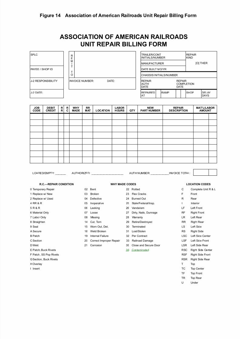
8/23/2019 AAR Intermodal Interchange Rules
http://slidepdf.com/reader/full/aar-intermodal-interchange-rules 90/224
Figure 14 Association of American Railroads Unit Repair Billing Form
ASSOCIATION OF AMEICAN AILOADS
NIT EAI BILLING FOM
SPLC R
EMIT
TO
TRAILER/CONTINITIALS/NUMBER
REPAIRKIND
MANUFACTURER [O] THER
PAYEE / SHOP ID DATE BUILT MO/YR
CHASSIS INITIALS/NUMBER
J-2 RESPONSIBILITY INVOICE NUMBER: DATE: REPAIR AUTHDATE
REPAIRCOMPLETIONDATE
J-2 DATE: REPAIRED AT
RAMP SHOP DELAYDAYS
JOBCODE
DEBITCEDIT
C
WHYMADE
MAT LOCATION
LABOHOS QTY
NEWAT NMBE
EAIDESCITION
MATLLABOAMONT
LOADED/EMPTY: _______ AUTHORIZED: _____________________ AUTH NUMBER: ____________INVOICE TOTAL:
CEAI CONDITION WHY MADE CODES LOCATION CODES
0 Temporary Repair 02 Bent 22 Rotted C Complete Unit R & L
1 Replace w/ New 03 Broken 23 Flex Cracks F Front
2 Replace w/ Used 04 Defective 24 Burned Out R Rear
4 RR & R 05 Inoperative 25 State/Federal/Insp. I Interior
5 R & R 06 Leaking 26 Vandalism LF Left Front
6 Material Only 07 Loose 27 Dirty, Nails, Dunnage RF Right Front
7 Labor Only 08 Missing 28 Warranty LR Left Rear
8 Straighten 14 Cut, Torn 29 Retire/Destroyed RR Right Rear
9 Seal 15 Worn Out, Det. 30 Terminated LS Left Side
A Secure 18 Weld Broken 31 Lost/Stolen RS Right Side
B Patch 19 Internal Failure 32 Per Contract LSC Left Side Center
C Section 20 Correct Improper Repair 33 Railroad Damage LSF Left Side Front
D Weld 21 Corrosion 35 Close and Secure Door LSR Left Side Rear
E Patch, Buck Rivets 36 Contaminated RSC Right Side Center
F Patch, SS Pop Rivets RSF Right Side Front
GSection, Buck Rivets RSR Right Side Rear
H Overlay T Top
I Insert TC Top Center
TF Top Front
TR Top Rear
U Under

8/23/2019 AAR Intermodal Interchange Rules
http://slidepdf.com/reader/full/aar-intermodal-interchange-rules 91/224
Figure 15 Association of American Railroads Tire Repair Billing Form
ASSOCIATION OF AMERICAN RAILROADSTIRE REPAIR BILLING FORM
SPLC
REMIT TO TRAILER/CONTAINERINITIALS/NUMBER
REPAIR KIND
PAYEE/SHOP ID
MANUFACTURER/
DATE BUILT MO/YR
J2 RESPONSIBILITY INVOICE NUMBER:CHASSISINITIALS/NUMBER
J2 DATE DATE: REPAIR DATE
JOBCODE
DEBITCREDIT
RR
RC
WHYMADE
RRMAT LOCATION
LABORHOURS QTY TIRE SIZE REPAIR DESCRIPTION
MATERIAL/LABOR AMOUNT
Invoice Total:
Loaded/Empty___________________Authorized:_________________________ Authority Number:_____________
Tires Loc BrandSerialNo.
CappersCode Tires Loc Brand
SerialNo.
CappersCode Tires Loc Brand
SerialNo.
CappersCode
Applied
Removed
R.R.-REPAIRRESPONSIBILITY R.C. - REPAIR CONDITION Why Made Location Codes
01 Assoc. w/Repairs
01 Owner 1 Replace W New 08 Missing ROR Right Outside Rear
03 J-2 3 Replace W Refmg Recap 09 Slick Tread RIR Right Inside Rear
07 Other 7 Labor Only 10 Separated Cap ROF Right Outside Front
08 Form J-1 B Patch 11 Blister, Knots RIF Right Inside Front
09 Damage 13 Run Flat ROQ Right Outside Quad
14 Cut, Torn RIQ Right Inside Quad
16 Flat Tire ROC Right Outside Center
17 Weather Chk/Chan. Crack RIC Right Inside Center
20 Correct Improper Repair LOR Left Outside Rear
34 Slid Flat LIR Left Inside Rear
LOF Left Outside Front
LIF Left Inside Front
LOQ Left Outside Quad
LIQ Left Inside Quad
LOC Left Outside Center
LIC Left Inside Center

8/23/2019 AAR Intermodal Interchange Rules
http://slidepdf.com/reader/full/aar-intermodal-interchange-rules 92/224 –74– 11/1/2010
AAR Intermodal Interchange Rules
APPENDIX A BILLING PROCEDURES
A11. Organization of Job Codes
a. 1000–1999—Tires/Rims
b. 2000–2799—Suspension and Tandems
c. 2800–2999—Air Ride
d. 3000–3999—Unders Construction—Below Floor, Except Tandem
e. 4000–4999—Body Construction
f. 5000–5099—Chassis Frame
g. 5100–5299—Chassis Rack
h. 5300–5399—Containers
i. 5400–5899—Miscellaneous
j. 5900–5999—Vacant
k. 6000–6299—Mechanical Refrigeration/Heater Units
l. 6300–6499—Vacant
m. 6500–6799—Tank Containers
n. 6800–6990—Vacant
o. 6991–6999—Taxes
p. 7000–7999—Reserved for Expansion
q. 8000–9999—Reserved for Individual Railroads

8/23/2019 AAR Intermodal Interchange Rules
http://slidepdf.com/reader/full/aar-intermodal-interchange-rules 93/224
11/1/2010 –75–
AAR Intermodal Interchange Rules
APPENDIX BCORRECT UNIT REPAIR PROCEDURES
APPENDIX B
CORRECT UNIT REPAIR PROCEDURES
B1. Introduction
a. Preface
This Appendix details procedures and methods for the repair of trailer, container, and chassisequipment to permit its safe return to service. The purpose of any repair is to restore theequipment to its original structural integrity; therefore, this Appendix describes the materials andmethod required by the AAR Intermodal Interchange Rules. All repairs and replacements aresubject to the applicable provisions of this Code of Rules and all regulatory specifications.
This Appendix is divided into sections detailing repairs by component groups.
b. Proper Repairs
It is important that each area of defect on a unit be carefully evaluated and proper repairs and/or replacements be made. The types of unit defects discussed in this repair manual are notintended to indicate that they are the only types of structural defects that should be repaired.Each unit or area of defects should be reviewed individually and a repair decision made basedon that review.
c. Equipment Component Compatibility
Original equipment components as manufactured, approved, and recommended by the builder of the unit are selected for their compatibility with each of the other elements of the unit;therefore, only original replacement parts or compatible materials should be used for recommended repairs.
d. Owner’s Requirements
If the owner’s standard(s) for applicable repair or replacement of specific component(s) arestenciled on the unit, such repair or replacement must be followed as prescribed in Rule 99.
e. Tamper Evidence Requirement
All repairs must be completed in a manner that makes it impossible to add or remove ladingwithout visible traces of repair tampering.

8/23/2019 AAR Intermodal Interchange Rules
http://slidepdf.com/reader/full/aar-intermodal-interchange-rules 94/224 –76– 11/1/2010
AAR Intermodal Interchange Rules
APPENDIX B CORRECT UNIT REPAIR PROCEDURES
B2. General Trailer/Container Repairs
a. Post and Panel Damage
Generally, post and/or panel damage can be repaired by splices and/or patches (refer to Body
Repairs, following). If the extent of the damage is such that an effective structural repair byreinforcing the damaged area is questionable, replacement of parts is recommended rather than splicing and/or patching. All post and panel damage to be repaired should be evaluated onan individual basis and repairs made based on that review. In all cases, the original trailer or container manufacturer should be consulted for repair recommendations.
b. Joining Dissimilar Materials
Joining of dissimilar metals and other materials involves procedures that will, if done properly,prevent or control corrosion that may occur in certain atmospheric or moisture conditions.Improper application of protective coatings between surfaces of dissimilar metals can leave thematerials open to severe galvanic actions. (In refrigerated trailers or containers, for example,when the space between two different metals is filled by a fluid that can conduct electricity, oneof the metals will gradually decompose.) Corrosion also occurs when wood parts are notprotected adequately prior to their assembly to metal surfaces.
The procedures listed below will, within practical limits, prevent such corrosion.
(1) Joining Aluminum to Unfinished Steel or Stainless Steel
(a) Before assembling aluminum to steel, including crossmembers to bottom rail, thesurface of the steel must be cleaned of all rust, scale, weld flux, metal particles, andother foreign material.
(b) Immediately after cleaning:
1) Apply a primer to the steel surface to prevent galvanic action.
2) Apply a protective coating to the steel area.
3) Apply insulating tape.
(c) Exterior steel number and logo placards and similar exposed steel items shall beprotected with insulating tape prior to assembly to an aluminum surface.
(d) Replacement fasteners must be of similar metals; screws, bolts, nuts, and nails; andprotective coatings must be used.
(2) Joining Aluminum and Wood Components
(a) Apply a protective coating to wood surfaces.
(b) Sealers that are flexible and non-shrinking shall be used in highly corrosive areasto prevent deterioration of the wood, including trailer or container doors and door frame areas.

8/23/2019 AAR Intermodal Interchange Rules
http://slidepdf.com/reader/full/aar-intermodal-interchange-rules 95/224
11/1/2010 –77–
AAR Intermodal Interchange Rules
APPENDIX BCORRECT UNIT REPAIR PROCEDURES
(3) Joining Metal to FRP Panels
(a) Although FRP (fiberglass reinforced plywood) panels are constructed with afiberglass outer layer, a protective coating must still be applied between the steelcomponent and FRP panel.
(b) Reference (2), Joining Aluminum and Wood Components, above, for correctprocedures.
B3. Body Repairs (Side Panels)
a. Mating of Panels
Material selected for replacing side wall panels shall comply with the manufacturer’srecommendation, with corrugated or smooth panel construction mated under all circumstances,including patches. Prepainted panels must likewise be mated.
b. Patching Body Panels of Sheet and Post Trailers and Containers
(1) A patch panel of like material shall be made to overlap the existing panel break of notless than 1 inch on all sides for small repairs. On larger breaks, the damaged portionmust be trimmed to produce a round or oblong opening. No patch shall be less than 4inches on any one side (see Figure B-1).
Figure B-1 Patching Panels
(2) Aluminum and steel panel patches shall be the same thickness as the original.
(3) Clean and deburr both panel and patch. Smooth any dented or creased area aroundthe damaged area.
(4) Place the panel patch over the break to include any badly dented or creased areas; drillholes for rivet securement around the patch perimeter, spaced on 1 ½ inch centers.Rivet holes shall be located not less than ½ inch from the edges of the patch.

8/23/2019 AAR Intermodal Interchange Rules
http://slidepdf.com/reader/full/aar-intermodal-interchange-rules 96/224 –78– 11/1/2010
AAR Intermodal Interchange Rules
APPENDIX B CORRECT UNIT REPAIR PROCEDURES
(5) Apply a non-shrinking sealer between the patch and trailer body.
One bead must be applied around the perimeter of the damaged area. The other beadmust be adjacent to the rivet line, and applied in a manner that does not allow anexcessive amount of sealant to seep to the outside perimeter of the patch.
(6) A self-sealing pop rivet is the correct hardware to use on side panel repairs (excludesdrive rivets and screws).
(7) For securement of panels to posts to the trailer or container structure, buck rivets and/or structural mono bolts must be used. Self-sealing pop rivets may be used only at therail area where there is no rear access due to the trailer’s or container’s structuralconfiguration.
(8) A patch cannot extend from one panel to another (Figure B-1a).
Figure B-1a Patching Panels
(9) Cuts the full length of a single panel in the area of the top or bottom rail must besectioned. Sections must be a minimum of 9 inches. All sections must be buck riveted.

8/23/2019 AAR Intermodal Interchange Rules
http://slidepdf.com/reader/full/aar-intermodal-interchange-rules 97/224
11/1/2010 –79–
AAR Intermodal Interchange Rules
APPENDIX BCORRECT UNIT REPAIR PROCEDURES
c. Patching Body Panel of Steel Container
Use of the correct type of steel, as well as proper surface preparation and painting methods, iscritical.
(1) Straightening
Whenever possible, straighten dents and compression lines in panels by mechanicalor hydraulic means without heating. It should not be necessary to use heat. Repairinga panel by straightening should return it to its original profile. If the damage hasstretched the panel to such an extent that the original profile cannot be restored, repair by straightening should not be attempted.
(2) Straightening and Welding
To repair cracks, splits, cuts, tears, or pin holes when the original profile can berestored, straighten the damaged area: drill a stop hole at each end of any crack and
weld the edges of the cut material to close the opening. Clean, mask, and prime therepaired area on both sides.
(3) Inserting
(a) If the damage cannot be repaired by straightening, a butt-welded insert may beinstalled (see Figure B-2). Inserts may straddle an existing panel weld seam if thedamaged area is on or near such a seam. Inserts may not be suitable if the damagecovers a large area adjacent to a rail or post or if nearby inserts are corroded or improperly installed and must be corrected.
Figure B-2 Panel Insert

8/23/2019 AAR Intermodal Interchange Rules
http://slidepdf.com/reader/full/aar-intermodal-interchange-rules 98/224 –80– 11/1/2010
AAR Intermodal Interchange Rules
APPENDIX B CORRECT UNIT REPAIR PROCEDURES
(b) Remove any attachments (ventilators, marking plates, etc.) that are within thedamaged area or near enough that they may be damaged during repair.
(c) Mark and cut out the damaged area with a torch or cutting disc. Cut the replacementmaterial to size. Inserts must be fitted flush with the existing panel and should be
fabricated to allow no more than 2 mm (5/64 in.) clearance between adjoiningsurfaces. Panel insert material must have the same corrugation size, profile, andradii as the original panel.
(d) Fit the insert into the cut-out area and tack-weld in position. Continuously weld theinsert on the exterior side of the existing panels. Ensure that insert welds fullypenetrate the panel to the interior side.
(e) Clean, mask, and prime the repaired area on both exterior and interior sides. Applytop coat to the exterior side only.
(f) Replace markings removed during repair that are required by regulation or as
directed by the owner. Reattach any other components that were removed duringthe repair.
d. Panel Replacement of Sheet and Post Trailers and Containers
(1) Sufficient panel lap is required to provide both a good seal and proper installation (seeFigure B-3).
Figure B-3 Panel Overlay
(2) Place the panel over the opening and drill around the panel perimeter, placing the holes
on 1½ inch centers. If an existing rivet hole is used, it must be reamed to provide a tightfit by use of a larger size rivet.
(3) The placement area and existing adjacent panels must be cleaned and deburred wherethey lap.
(4) Use applicable aluminum alloy or high tensile cadmium-plated steel rivets.

8/23/2019 AAR Intermodal Interchange Rules
http://slidepdf.com/reader/full/aar-intermodal-interchange-rules 99/224
11/1/2010 –81–
AAR Intermodal Interchange Rules
APPENDIX BCORRECT UNIT REPAIR PROCEDURES
(5) For securement of panels to posts to the trailer or container structure, buck rivets and/or structural mono bolts must be used. Self-sealing pop rivets may be used only at railarea where there is no rear access due to the trailer or container structureconfiguration.
(6) A side post should never be spliced. If badly bent or cut, the interior post should bereplaced before the section or full panel is replaced.
e. ) Panel Replacement of Steel Box Containers
If an individual panel cannot be repaired by straightening or inserting, the damaged panel maybe removed and replaced with a new panel. Replacement also may be indicated if insertingwould leave nonconforming repairs nearby or if replacement is less expensive. Butt-welded
joints between the replacement and existing panels are required.
f. FRP Panel Damage
(1) General
In all cases, the original trailer or container manufacturer should be consulted for repair recommendations.
(2) Damage Categories
FRP panel damages normally fall under four categories:
(a) Minor surface damage—This damage requires only repair of the resin or surfacefinish. This may be accomplished by using the manufacturer’s recommended repair kit.
(b) Damage that goes through the glass fibers and into the plywood—Thisdamage requires that the damaged area be cleared back to sound materials, andrepaired with glass mat, resin, and surface finish.
(c) Puncture damage that goes completely through the panel—This damagerequires that both faces of the panel be repaired.
(d) Severely smashed or damaged panels—In this case, the complete damagedarea must be removed and replaced. In some cases, complete panel replacementmay be necessary.

8/23/2019 AAR Intermodal Interchange Rules
http://slidepdf.com/reader/full/aar-intermodal-interchange-rules 100/224 –82– 11/1/2010
AAR Intermodal Interchange Rules
APPENDIX B CORRECT UNIT REPAIR PROCEDURES
(3) Non-Puncture Damage Repair
(a) Determine the extent of the damage. Measure and mark a 4 inch area outside thedamage, and draw in 2 inch lines for the feathered area. Score along the inside lineswith a sander, and peel off all damaged fiberglass. Disc sand to remove all
damaged plywood. Feather the area where exposed wood and fiberglass of theoriginal panel meet. Remove dust. If moisture exits, dry with heat lamps.
(b) Using wide masking tape, make a rectangular border around the repair area. Sandthe gel-coat surface inside the rectangle to roughen the smooth surface enough for good adhesion. Mix resin compound to accurate proportions and apply to the entirerepair area. Fill in center depressions with an extra layer of resin to help eliminateair bubbles.
(c) Saturate a section of woven fiberglass with resin compound. Position it over boththe wood and feathered area. Cover the entire repair area with remainder of theresin.
(d) Cut a piece of mylar film large enough to overlap onto the masking tape. Attach thetop edge of film onto the top border of the tape. Use a roller to squeeze out excessresin compound, along with any air bubbles, level to the surface of the originalpanel.
(e) After curing is completed, sand the entire repair. Dust off, and fill small imperfectionswith polyester body filler or glazing compound. If a few pinholes persist after sanding the polyester, apply spot filler. Prime and paint if desired.
(4) Surface Repair
(a) The surface must be clean and dry before the patch can be applied. Remove allsmoke and residual dirt from the repair area with clear, hot water, and then wipe drywith a clean, absorbent cloth.
(b) After removing any projecting fibers, apply polyester body filler mixed with anappropriate amount of cream hardener, leveling it so the surface is smooth andclean.
(c) From a roll of adhesive-backed repair film, cut a length slightly larger than thedamaged area. Peel back the leading edge of paper liner and fold it down, exposingthe adhesive surface.
(5) Replacement of Damaged Section
(a) Examine the severity of the damage. Tap the surrounding area to determine theextent of delamination. Mark a rectangle about 4 inches larger than apparentdamage.
(b) Cut out the marked section. Inspect the perimeter for wetness. If moisture ispresent, drill small holes a few inches apart to determine the extent of moisture.Recut the opening larger if necessary.

8/23/2019 AAR Intermodal Interchange Rules
http://slidepdf.com/reader/full/aar-intermodal-interchange-rules 101/224
11/1/2010 –83–
AAR Intermodal Interchange Rules
APPENDIX BCORRECT UNIT REPAIR PROCEDURES
(c) From inside the trailer or container, mark a line 2 inchesfrom the opening to prepareto make a shiplap joint. Preset your saw to a depth half the thickness of the panel,then make the cut. Peel away the fiberglass part of the panel “sandwich” from theplywood.
(d) Remove the plywood to the depth of the cut with a chisel or router. Sand it smoothwith a high-speed rotary sander and a 32-grit disc.
(e) Cut a plug from an FRP panel of the same thickness, 2 inches larger than theopening on all sides. Draw a line 2 inches in from the edge of the plug’s finishedside. Cut to a depth half way through the panel. Remove the 2 inch strip of fiberglassand plywood, as previously described. Sand smooth. Clean the area. Place the plugin the opening, and then make necessary adjustments.
(f) Apply resin compound generously to cover all sanded areas. Fill all voids.
(g) Insert the plug of FRP panel. Place temporary fasteners, either screws or bolts,
strategically around the perimeter to hold the plug in place until the resin compoundcures. Remove excess resin compound. While the compound hardens, cutappropriate length 4 inch and 8 inch strips of woven fiberglass to cover all edges of the repair as preparation for lay-up later.
(h) When the compound has set up, remove the temporary fasteners and sand off anyexcess resin. Draw lines 2 inches on both sides of the joint. Using a sander or saw,score the fiberglass and remove a 2 inch strip on each side of the joint.
(i) Feather an additional 2 inch on all sides of the 2 inch strip of exposed plywood,working through the surface, but not through the woven fiberglass laminate. Sandwith a back-and-forth motion to avoid heat build-up and possible delamination.
(j) After thorough mixing, completely cover sanded areas with the polyester resincompound. Lay a proper length of 4-inch-wide woven fiberglass on the resin-coatedbare wood surface of the top horizontal section. Press the fiberglass into the moistresin. Immediately apply a thin layer of resin compound over the 4 inch strip, alsocovering the feathered area.
(k) Immediately lay on an 8 inch strip of woven fiberglass over the 4 inch strip,extending into the feathered original laminate, applying pressure to saturate thecloth. Follow with liberal amounts of additional resin compound.
(l) Cut a piece of film large enough to cover the lay-up. Tape the top edge of the film
several inches above the top of the resin-covered area.
(m) With a roller, apply steady, continuous, firm pressure in one direction across thefilm-covered area to force out air bubbles and ensure complete saturation of thewoven fiberglass. Discard excess resin. Repeat the same procedure for the bottomhorizontal section. Leave the film taped in place, and work on the outside of thetrailer or container, repeating the previous steps.
(n) When the interior horizontal sections have cured, remove the mylar strips and lightlyfeather the corners to make smooth joints. Repeat this procedure on the verticalstrips. Following horizontal curing, sand high points for a smooth surface. Also applyvertical strips to outside.

8/23/2019 AAR Intermodal Interchange Rules
http://slidepdf.com/reader/full/aar-intermodal-interchange-rules 102/224 –84– 11/1/2010
AAR Intermodal Interchange Rules
APPENDIX B CORRECT UNIT REPAIR PROCEDURES
(o) Fill any small imperfections with polyester body filler or body glazing compoundbefore and after sanding. If a few pinholes persist after sanding the polyester, applyspot filler and sand again until the desired finish is obtained.
(p) Mask off the patch, and prime the entire repair (if painting is desired). After the
primer dries, spray on two coats of paint.
(q) The completed patch should offer the same structural integrity and near-perfectsurface as the original fiberglass panel.
B4. General Interior Repairs
a. Floors
(1) Floor Structure and Damage
The floor of a trailer or container is a key element of the structural system. In addition to the
normal vertical loads, it carries longitudinal loads such as dock bumps, etc. Floors in trailersor containers are normally of glued, laminated hardwood, that is, in most cases, one piece,the full length of the trailer or container, and approximately 12 inches wide. The trailer or container floor consists of three main structural components that serve to support a fork liftand to transfer the load to the side panels. These components include the floorboards, thefloor supports or crossmembers, and the crossmember supports or crossmember-to-railconnectors.
The crossmember supports are the most critical of the three structural components, be-cause their failure could lead to the total collapse of the entire floor system.
Damage to floors is the result of overloading, mechanical handling trucks in the trailer, or
deterioration of the floor well over the life of the trailer or container. This will result insections that are weaker and will fail at a lower load level. Occasionally, a heavy piece of freight can puncture the floor in a local area, resulting in a floor failure.

8/23/2019 AAR Intermodal Interchange Rules
http://slidepdf.com/reader/full/aar-intermodal-interchange-rules 103/224
11/1/2010 –85–
AAR Intermodal Interchange Rules
APPENDIX BCORRECT UNIT REPAIR PROCEDURES
(2) Flooring Repairs
Proper repairs to a broken floor section are mandatory, so that the integrity of the remainingfloor is not affected by the repair. The following repair procedures must be followed:
(a) Flooring replacements shall fasten to a minimum of three crossmembers. Noadjacent flooring repairs shall end on the same crossmember; however, end jointsmust be staggered and sealed (Figure B-4).
Figure B-4 Floor Repairs
(b) All repairs to flooring or decking must be of a similar quality and like installation as
the original flooring, be free of visible defects, and be top-coated/undercoated.
(c) Before starting repairs, it is recommended that an inspection of the crossmembersin the area of the board failure be made to determine if any crossmembers are inneed of repair or replacement.
(d) In the event of floor area damage, determine the extent of the damage and indicatethe extremes of the damage. Repair as follows:
8/23/2019 AAR Intermodal Interchange Rules
http://slidepdf.com/reader/full/aar-intermodal-interchange-rules 104/224 –86– 11/1/2010
AAR Intermodal Interchange Rules
APPENDIX B CORRECT UNIT REPAIR PROCEDURES
1) From the point at which the damaged area stops, proceed in a forward andrearward direction at least one additional crossmember space, and mark thefloor. Remove the floor screws in adjacent boards that will allow the damagedfloor section to be raised above floor level, and cut the damaged boards atthe points marked. Obtain an identical section, thickness, and variety of
lumber for replacement.
2) Cut a section of the replacement lumber to a length compatible with theremoved material. Apply a bead of butyl or silicone caulking to the matingperimeter edges of the floorboard, and lay in place, ensuring that the jointbetween adjacent boards interlocks.
3) Reinstall any missing fasteners in adjacent boards, and drill a minimum of three holes through the new board plank at each crossmember location.Install 2-inch-long self-tapping flat-head screws at each location.
4) Install a bead of caulk across the butt joint between the new and adjacent floor
planks to ensure against leakage.
5) In situations where extensive damage is done to a floor and more than onefloor board is damaged, be sure to install replacement planks so that no twoadjacent butt joint conditions exist at any one crossmember. If necessary,stagger the joints by installing longer-than-required floor replacement insertsat adjacent positions. This is extremely important. Any distortion that resultsin the lack of contact between the floor and the crossmember can beremedied by reinstalling screws through the floor and positioning nuts on thebottom shank of the screw, thereby clamping the floor and crossmember together.
6) The butt gap between boards shall not exceed ¼ inch.
b. Side Liners
(1) Repair/replacement materials shall be the same quality, type, and thickness as theoriginal liner material.
(2) The installation of ply-liners should use the same type fasteners as used in the originalinstallation.
(3) If a ply-liner has a hole greater than 4 inches, the ply-liner should be replaced.
c. Scuff Liner
The scuff liner and fasteners must be of like material as the original installation. Sectioning isacceptable, with end joints located at a side post.
8/23/2019 AAR Intermodal Interchange Rules
http://slidepdf.com/reader/full/aar-intermodal-interchange-rules 105/224
11/1/2010 –87–
AAR Intermodal Interchange Rules
APPENDIX BCORRECT UNIT REPAIR PROCEDURES
d. Roof
If the trailer or container is equipped with a plywood liner, replacement must be of the samequality, type, and thickness as the original. (See B6, Roof Repairs, for specific roof repairs.)
B5. Trailer or Chassis Support Repairs
a. Landing Legs
(1) Description
The landing leg system (see Figure B-5 and Figure B-6) has been designed to provide astable support for the trailer or chassis and is located from centerline of the kingpin.Manually operated landing gears must be of two speeds, and the legs must be equippedwith heavy-duty wheels and/or pads and heavy-duty axles.
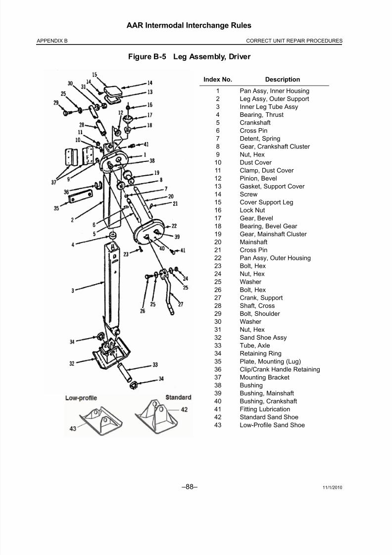
8/23/2019 AAR Intermodal Interchange Rules
http://slidepdf.com/reader/full/aar-intermodal-interchange-rules 106/224 –88– 11/1/2010
AAR Intermodal Interchange Rules
APPENDIX B CORRECT UNIT REPAIR PROCEDURES
Figure B-5 Leg Assembly, Driver
Index No. Description
1
23
4
5
6
7
8
9
10
11
12
13
1415
16
17
18
19
20
21
22
23
24
25
2627
28
29
30
31
3233
34
35
36
37
38
39
40
4142
43
Pan Assy, Inner Housing
Leg Assy, Outer SupportInner Leg Tube Assy
Bearing, Thrust
Crankshaft
Cross Pin
Detent, Spring
Gear, Crankshaft Cluster
Nut, Hex
Dust Cover
Clamp, Dust Cover
Pinion, Bevel
Gasket, Support Cover
ScrewCover Support Leg
Lock Nut
Gear, Bevel
Bearing, Bevel Gear
Gear, Mainshaft Cluster
Mainshaft
Cross Pin
Pan Assy, Outer Housing
Bolt, Hex
Nut, Hex
Washer
Bolt, HexCrank, Support
Shaft, Cross
Bolt, Shoulder
Washer
Nut, Hex
Sand Shoe Assy
Tube, Axle
Retaining Ring
Plate, Mounting (Lug)
Clip/Crank Handle Retaining
Mounting Bracket
Bushing
Bushing, Mainshaft
Bushing, Crankshaft
Fitting Lubrication
Standard Sand Shoe
Low-Profile Sand Shoe

8/23/2019 AAR Intermodal Interchange Rules
http://slidepdf.com/reader/full/aar-intermodal-interchange-rules 107/224
11/1/2010 –89–
AAR Intermodal Interchange Rules
APPENDIX BCORRECT UNIT REPAIR PROCEDURES
Figure B-6 Support Frames and Supports
Index No. Description
1
2
3
4
5
6
7
8
910
Zee Assembly (Generally 5
X-Members)
Support Mounting/V-Brackets/
Mounting Skirts
Strut Assembly or
Diagonal Brace
Crossbrace
Diagonal Brace
Cross Shaft
Leg Assy, Driven
(Single Speed, Slave)
Leg Assy, Driver (Two
Speed, Gearside)
Removable Fastener Crank Handle
NOTE: Use of minimum Grade 5 bolt
required.

8/23/2019 AAR Intermodal Interchange Rules
http://slidepdf.com/reader/full/aar-intermodal-interchange-rules 108/224 –90– 11/1/2010
AAR Intermodal Interchange Rules
APPENDIX B CORRECT UNIT REPAIR PROCEDURES
(2) Defects
When a landing gear lower leg and/or upper leg assembly is bent, damaged, or deformedto a point that will not allow free vertical travel, the leg(s) should be replaced.
The normal defects associated with non-functional landing gear are:
(a) Broken welds
(b) Loose fasteners (missing, broken, defective, or improper materials)
(c) Legs improperly adjusted
(d) Defective components (bent or broken)
(e) Dry or insufficient lubricant
(3) Repair Comparability Required
(a) If other than the original type legs are installed, the bolt patterns, gear ratio, and loadrating must be compatible.
(b) Landing leg braces that have been bent or damaged should be straightened, if practical, or replaced, if necessary, with a new one of like kind or equal strength tothe original.
(4) Component Replacement vs. Leg Replacement
When a landing leg is defective due to internal component failure without damage to the
leg assembly, the components should be replaced, if necessary, in lieu of replacing theentire leg. Reassembly must include proper lubrication.
(5) Landing Gear Mounting Bracket
If damage to the landing gear mounting bracket is such that it is impractical to repair and itmust be replaced, the replacement bracket must be of like kind as original equipment. Thebolt-on type requires a direct one-for-one replacement, utilizing identical fastener patternsand sizes as the original installation.
(a) In replacing the weld-on bracket, care must be taken to remove the damagedbracket without distorting, bending, or cutting through mounting surfaces adjacentto the bracket. If this is not possible, crossmembers directly over the landing gear must also be replaced with the bracket.
(b) Mounting brackets must be attached as established on original equipment.
(6) Sand Shoes, Dolly Wheels, and Axles
When is it necessary to replace sand shoes, dolly wheels, and/or axles, the replacementmust be of like size, shape, and strength as the opposite position and must be properlysecured.

8/23/2019 AAR Intermodal Interchange Rules
http://slidepdf.com/reader/full/aar-intermodal-interchange-rules 109/224
11/1/2010 –91–
AAR Intermodal Interchange Rules
APPENDIX BCORRECT UNIT REPAIR PROCEDURES
(7) Landing Gear Crank Handle
When it is necessary to replace the landing gear crank handle, the replacement must be of sufficient size and shape to clear the side of trailer or container and must store in existingstorage retainer.
(8) Cross Shaft
When it is necessary to replace the cross shaft, the replacement must be of the same size,shape, and strength as that of the original equipment. A removable fastener must be usedin installation.
B6. Roof Repairs
a. General
Roof repairs (see Figure B-7) are equally, if not more, important than repairs to the nose or side
walls of a trailer or container. Correct materials and good workmanship can determine if therewill be load damage caused by weather. Roof panels that have a tear or hole should be repairedto prevent structural failure and water damage to cargo. Generally, repairs consist of a relativelysimple patch or replacing a section of roof panel the full width of the trailer or container,extending to the nearest roof bows adjacent to the damaged area. Certain procedures must,therefore, be followed when roof repairs are made.

8/23/2019 AAR Intermodal Interchange Rules
http://slidepdf.com/reader/full/aar-intermodal-interchange-rules 110/224 –92– 11/1/2010
AAR Intermodal Interchange Rules
APPENDIX B CORRECT UNIT REPAIR PROCEDURES
Figure B-7 Roof Sheet Edge Treatment
b. Patching Roof Sheet
(1) Care must be exercised to ensure that roof repairs are properly extended to the roof bows and given a good exterior seal to afford maximum long life to the repair and toavoid loosening of roof sheet by flexing. Patch is not to be riveted through the roof bow.

8/23/2019 AAR Intermodal Interchange Rules
http://slidepdf.com/reader/full/aar-intermodal-interchange-rules 111/224
11/1/2010 –93–
AAR Intermodal Interchange Rules
APPENDIX BCORRECT UNIT REPAIR PROCEDURES
(2) For small repairs, a patch shall be made to overlap the existing panel break of not lessthan 1 inch on all sides. On larger breaks, the damaged portion must be trimmed toproduce a round or oblong opening (same as side panels). No patch shall be less than4 inches on any one side.
(a) Aluminum and steel patches shall be the same thickness and type as original roof sheet.
(b) Clean and deburr both panel and patch. Smooth any dented or creased area arounddamage.
(c) Placing the patch over the break, drill holes for rivet securement around the patchperimeter, spaced on 1½ inch centers. Rivet holes shall be located not less than ½inch from the edges of the patch.
(d) Any roof bow damage shall be repaired prior to the application of the patch.
(e) Apply a sealer between the patch and roof sheet and around the edge of patch, withadditional sealer placed over the exterior rivet heads.
(f) Roof patches must be secured with soft buck rivets to prevent flexing and rivet holeelongation. Where the underside of the roof is inaccessible, repairs must be madewith self-sealing pop rivets. All roof bow repairs or replacements must be made withoriginal type fasteners or two-piece rivets.
(g) Holes must be drilled in the leading ends of any stress crack.
(h) When the patch extends to the top rail, buck rivets must be used.
c. Roof Sheet Breaks More Than 6 Inches
Sections on roof sheet breaks in excess of 6 inches shall extend to and be secured adjacent toroof bows. If the trailer or container is so constructed, the section applied must be bonded toroof bows.
(1) If damage requires removal of original roofing from the top rail, the entire original roof sheet must be sectioned and replaced to the nearest end.
(2) If the roof has been previously sectioned in the area of damage, the new section mustbe extended beyond the previous section.
(3) If the area to be sectioned exceeds 30% of the roof, the entire roof must be replaced.
(4) No more than three sections shall make up the entire roof. (The splice on a stretchtrailer is counted as one section and would therefore be a two-sectioned roof.) The cen-ter of the roof sheet cannot be spliced.
(5) Roof patch cannot exceed 12 inches by 36 inches.

8/23/2019 AAR Intermodal Interchange Rules
http://slidepdf.com/reader/full/aar-intermodal-interchange-rules 112/224 –94– 11/1/2010
AAR Intermodal Interchange Rules
APPENDIX B CORRECT UNIT REPAIR PROCEDURES
d. Roof Replacement—Aluminum (Dry Van or Container)
(1) A one-piece aluminum sheet must be used.
(2) All damaged roof bows must be removed and replaced with new roof bows and secured
at each end to the top rail by use of huck-type fasteners or manufacturer’s original-typefasteners.
(3) After removal of the old roof sheet and subsequent to any roof bow replacement, all roof bows and rail gutters must be cleaned and deburred.
(4) Before installing new roof, apply a sealer on the roof rail or in the roof rail gutter aroundthe entire trailer or container.
(5) The roof sheet must be secured to the front rail, spaced as recommended by themanufacturer.
(6) The trailer or container must be on a level ground surface when a new roof is applied.The new roof sheet must be stretched in place by using clamps or roof stretchers at therear header of the trailer or container. (This phase is very important to reduce thepossibility of roof sheet flapping, which could cause flex cracking.)
(7) The sides of the new roof sheet must be affixed to the top rails and rear headersaccording to the manufacturer’s specification.
e. Roof Bows
Roof bows that are broken or missing should be replaced. Due to the wide variety of designs,the original trailer or container manufacturer should be consulted for its recommendations onbow replacements.
B7. Rear Doors and Rear Frame
a. General
The rear doors (see Figure B-8) are probably the most damaged component on an intermodaltrailer or container; therefore, certain repair procedures must be followed to maintain the overallstructural integrity of the trailer or container.

8/23/2019 AAR Intermodal Interchange Rules
http://slidepdf.com/reader/full/aar-intermodal-interchange-rules 113/224
11/1/2010 –95–
AAR Intermodal Interchange Rules
APPENDIX BCORRECT UNIT REPAIR PROCEDURES
Figure B-8 Rear Door Assembly
Index No. Description
1
23
4/5
6
7
8
9
10
11
12
13
14
15
Plymetal Door – 1¼”
Hinge Strap/ButtHinge Pin
Seal Pin (Handle Latch) Assy.
Door Handle
Upper/Lower Rod Guide
Upper/Lower Cam Keeper
Upper/Lower Cam
Lock Rod Pipe
Intermediate Rod Guide
Upper/Lower Rod Guide
Intermediate Rod Guide Bushing
Fastener
Door Tie Back Plate

8/23/2019 AAR Intermodal Interchange Rules
http://slidepdf.com/reader/full/aar-intermodal-interchange-rules 114/224 –96– 11/1/2010
AAR Intermodal Interchange Rules
APPENDIX B CORRECT UNIT REPAIR PROCEDURES
The door of a trailer or container is designed so that when loaded beyond the design load,failure will take place in the door locking hardware and not in the connections between the endframe (see Figure B-9) and the trailer or container body. The door and assembly are designedto withstand the maximum loads and fatigue forces imposed in rail operation. (Generally, thedoor end assembly consists of the door frame, doors, door hinges, door locking hardware, and
the attachment of these items.)
Figure B-9 Rear Frame Assembly
Index No. Description
1
2
3
4
5
6
7
8
9
10
Post, Rear Corner, Roadside & Curbside 12’ Lights
Header Assembly
Crossmember Assembly
Angle, Plywood Edge Protector
Hinge, Bracket
Bumper, Curb/Roadside
Light Protector
Upper Tie Plate, Roadside & Curbside
Lower Tie Plate, Roadside & Curbside
Bumper, Lower

8/23/2019 AAR Intermodal Interchange Rules
http://slidepdf.com/reader/full/aar-intermodal-interchange-rules 115/224
11/1/2010 –97–
AAR Intermodal Interchange Rules
APPENDIX BCORRECT UNIT REPAIR PROCEDURES
b. Repair Procedures
(1) Rear Doors
(a) Plating of rear doors is not permitted and shall not be considered a proper repair
(except as only a temporary repair). Self-sealing patches are allowable on cuts thatdo not extend more than 1/8 inch into the door plywood.
(b) All door replacements shall be made with like materials (gaskets, door hardware,door dimensions).
(c) When doors are mounted, they shall be mounted flush with the door frame and shallbe constructed such that the curbside door must be opened before the roadsidedoor can be opened.
(d) All decals and signs shall be replaced on new doors.
(e) The replacement of all tie-backs on new doors is required.
(2) Security Hardware
(a) Lock rods and hinge plates shall meet AAR M-931 specifications.
(b) When doors are replaced, the security plate must be replaced.
(c) All door-seal locking devices, door securement hardware, and door attachmenthardware must be affixed by fully welding or by the use of “tamper-proof” fastenersto preclude entry into the trailer or container by removal of any of the door hardwarecomponents. A minimum of one fastener on each of the top and bottom hinges andtop and bottom lock-rod support bearings shall be “tamper-proof.” All door seal haspfasteners also shall be “tamper-proof.”
1) Fasteners may be considered “tamper-proof” by virtue of their original designor because of alteration to reusable fasteners, which requires their destruction by burning or cutting to effect removal. Reusable fasteners, suchas nuts and bolts, are not recommended; if used, they must be secured byfully welding the nut to the bolt or the bolt to its mating hardware. (Fullywelding means welding around the entire circumference of the bolt.)Prevailing-torque fasteners utilizing deformed threads or plastic inserts arenot considered as “tamper proof” fasteners (except when they areinaccessible, such as on refrigerated trailer doors). Tack or spot welding is notpermissible.
(d) All door hardware shall have a hot-dip galvanized finish or functional equivalent.

8/23/2019 AAR Intermodal Interchange Rules
http://slidepdf.com/reader/full/aar-intermodal-interchange-rules 116/224 –98– 11/1/2010
AAR Intermodal Interchange Rules
APPENDIX B CORRECT UNIT REPAIR PROCEDURES
(3) Rear Door Frame
(a) Rear door headers are designed to protect all lights and wiring from mechanicaldamage during normal operations.
(b) Rear door lower sills are designed to protect lights, reflective lenses, and door lockkeepers from mechanical damage during normal operations, as typified by backinginto loading platforms and railcar bridge plates rubbing against the trailer duringtransit. Replacement rubber or fabric-type bumpers do not meet this requirement.
B8. Splicing of Side Rails and Protectors
a. Repair Procedures
Damages to the top or bottom rails will directly affect the overall integrity of the trailer or con-tainer and if not properly handled, could cause the total failure of the equipment. The followingconsiderations are involved with this type of repair (see Figure B-10, Figure B-11, and
Figure B-12):
(1) Manufacturer’s recommendations for repairs to top or bottom rail must be followed, withall splices adding adequate strength to the damaged area.
(2) No more than one splice per rail is allowed, except to a stretch trailer (see below).
(3) A spliced rail section shall not exceed 25% of the overall vehicle length. (Refer toFigure B-10)
(4) Splice Plates
(a) Splice plates must be of steel and/or aluminum; insulating tape must be usedbetween the aluminum and steel components.
(b) The bottom rail splice plate must extend a minimum of three crossmembers, and thetop rail splice plate must span a minimum of two posts.
(c) Splice plates on the top rail (per manufacturer specifications) can be installed oneither the interior or exterior of the rail.
(5) When a rivet is replaced with a bolt in a crossmember, it must have a minimum of atleast a Grade 5 bolt with a self-locking nut. Lock washers may never be used.
(6) The welding or plating of top or bottom rails as a means of a repair is prohibited if itdirectly affects the strength and/or integrity of the rail.
(7) Stretch Trailers
A stretched trailer has been modified by the original manufacturer’s specifications.Therefore, the stretch portion of the rails shall not be considered a splice.

8/23/2019 AAR Intermodal Interchange Rules
http://slidepdf.com/reader/full/aar-intermodal-interchange-rules 117/224
11/1/2010 –99–
AAR Intermodal Interchange Rules
APPENDIX BCORRECT UNIT REPAIR PROCEDURES
Figure B-10 “Rule of Thumb” for Trailer Splicing
b. Definitions
(1) Top Rail Protectors
Top rail protectors are non-structural attachments at side rails, located near the top side, toprotect the top rails and roof from contact with lift arms of lifting devices.
The bearing surface of top rail protectors is designed so as to prevent any contact of the liftarms of lifting devices with the trailer top rails or roof.
Top rail protectors are fastened to the trailer in a manner that prevents damage of top railprotector attachments by lift arms of lifting devices.
If splice(s) exist(s) at any A location, then splice is permitted at any other A location(s). If
splice(s) exist(s) at any B location, then splice is permitted at any other B location(s). Neither A location may be spliced if either B location on the same side is spliced. Neither B locationmay be spliced if either A location on the same side is spliced.
NOTE: No more than one splice section of rail is permitted in any top or bottom rail, exceptstretch trailers.

8/23/2019 AAR Intermodal Interchange Rules
http://slidepdf.com/reader/full/aar-intermodal-interchange-rules 118/224 –100– 11/1/2010
AAR Intermodal Interchange Rules
APPENDIX B CORRECT UNIT REPAIR PROCEDURES
(2) Lift Pads (Bottom Rail Protectors)
Lift pads are non-structural attachments at bottom side rails to protect crossmembers,bottom side rails, side walls, and mechanical fasteners located near the bottom of the sideand beneath the body from contact with lift shoes of lifting devices.
(a) The horizontal bearing surface of lift pads shall extend inwardly from the outsidevertical plane of the body a minimum of 6 inches. The vertical bearing surface shallextend upward from the bottom side rail a minimum of 2¼ inches. SeeFigure B-10a.
(b) Lift pads are fastened to the trailer in a manner that prevents damage of lift padfasteners by lift shoes of lifting machines.
Figure B-10a Trailer Lift Pads (Bottom Rail Protectors)
Unit Length (ft) Lift Pad Length (ft)
28 5
45 10
48 10
53 15 or full length
57 15 or full length

8/23/2019 AAR Intermodal Interchange Rules
http://slidepdf.com/reader/full/aar-intermodal-interchange-rules 119/224
11/1/2010 –101–
AAR Intermodal Interchange Rules
APPENDIX BCORRECT UNIT REPAIR PROCEDURES
Figure B-11 Splicing of Top Rails
NOTE: Splice plate has the option of being installed internally, externally, or both (as above)to top rail.
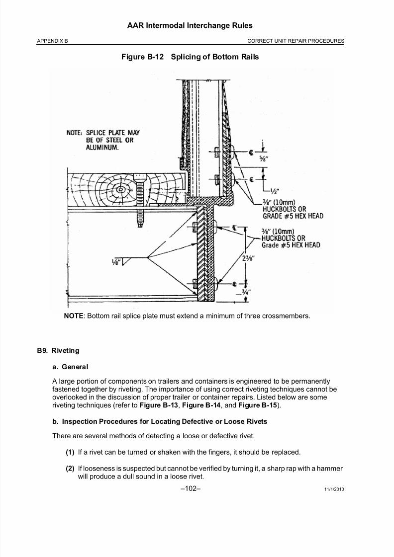
8/23/2019 AAR Intermodal Interchange Rules
http://slidepdf.com/reader/full/aar-intermodal-interchange-rules 120/224 –102– 11/1/2010
AAR Intermodal Interchange Rules
APPENDIX B CORRECT UNIT REPAIR PROCEDURES
Figure B-12 Splicing of Bottom Rails
B9. Riveting
a. General
A large portion of components on trailers and containers is engineered to be permanently
fastened together by riveting. The importance of using correct riveting techniques cannot beoverlooked in the discussion of proper trailer or container repairs. Listed below are someriveting techniques (refer to Figure B-13, Figure B-14, and Figure B-15).
b. Inspection Procedures for Locating Defective or Loose Rivets
There are several methods of detecting a loose or defective rivet.
(1) If a rivet can be turned or shaken with the fingers, it should be replaced.
(2) If looseness is suspected but cannot be verified by turning it, a sharp rap with a hammer will produce a dull sound in a loose rivet.
NOTE: Bottom rail splice plate must extend a minimum of three crossmembers.

8/23/2019 AAR Intermodal Interchange Rules
http://slidepdf.com/reader/full/aar-intermodal-interchange-rules 121/224
11/1/2010 –103–
AAR Intermodal Interchange Rules
APPENDIX BCORRECT UNIT REPAIR PROCEDURES
(3) A further check is to coat the rivet head with light oil, wait a few seconds for the oil topenetrate, wipe it clean, and rap it again with a hammer. If oil appears around the edgesagain, the rivet should be replaced.
(4) Finally, the appearance of evidence of movement or shifting between riveted parts,
such as bare or shiny areas, is a good indication of the need for replacement.
c. Proper Riveting Procedures
(1) Select a rivet length so that the shank before riveting protrudes through the material 1½times the diameter of the shank (Figure B-13).
Figure B-13 Proper Rivet Length
(2) Tools
The two most important tools for producing a good rivet application are the rivet set and thebucking bar.
(a) Rivet Set
It is important to select and use the correct rivet set and size that will match the head of the rivet being used. An oversized set will flatten the rivet head and damage the adjacentmaterial, while an undersized set will damage the rivet head. The rivet set is held in thegun by a retaining spring. Always be sure that the spring is securely in place prior tostarting. The strike of the rivet gun is adjustable and should be tested against a block of
wood to ensure proper strike.
NOTE: Soft rivets are prohibited in trailer repairs, except on roof repairs.

8/23/2019 AAR Intermodal Interchange Rules
http://slidepdf.com/reader/full/aar-intermodal-interchange-rules 122/224 –104– 11/1/2010
AAR Intermodal Interchange Rules
APPENDIX B CORRECT UNIT REPAIR PROCEDURES
(b) Bucking Bar
1) The bucking bar is used to produce the flat head (bucked head) on theopposite end of the rivet from the manufactured head. By using the correctbar properly, a bucked head should be produced that is 1½ times the diameter
of the rivet shank and ½ the diameter in thickness.
2) The weight of the bar being used has an effect on the riveting job. If the bar istoo light, it will require more action from the riveting gun and will consequentlycause damage to the material. A heavy bucking bar will work faster and willkeep the vibration of the gun from being transmitted to the mechanic’s hand.
3) Following are some of the basic rules for using a bucking bar:
a) One surface or side of the bucking bar is polished. This is known as the“face” and must be positioned and held correctly to create a proper bucked head.
b) Keep the face of the bar parallel to the material. If the bar is canted, thebucked head will be improperly formed, and the material will bedamaged.
c) The face of the bucking bar must cover the entire rivet end.
d) A firm hold on the bar will result in a smoother and faster job and willprevent “chatter.”

8/23/2019 AAR Intermodal Interchange Rules
http://slidepdf.com/reader/full/aar-intermodal-interchange-rules 123/224
11/1/2010 –105–
AAR Intermodal Interchange Rules
APPENDIX BCORRECT UNIT REPAIR PROCEDURES
Figure B-14 Good and Bad Rivet Heads

8/23/2019 AAR Intermodal Interchange Rules
http://slidepdf.com/reader/full/aar-intermodal-interchange-rules 124/224 –106– 11/1/2010
AAR Intermodal Interchange Rules
APPENDIX B CORRECT UNIT REPAIR PROCEDURES
Figure B-15 Solid Rivet Chart — Sizes and Ratings

8/23/2019 AAR Intermodal Interchange Rules
http://slidepdf.com/reader/full/aar-intermodal-interchange-rules 125/224
11/1/2010 –107–
AAR Intermodal Interchange Rules
APPENDIX BCORRECT UNIT REPAIR PROCEDURES
B10. Axles, Bearings, and Brakes
(See Figure B-16 and Figure B-17)
a. General
Several components in this manual have been discussed as being integral components of therail intermodal trailer or chassis; without the proper care and preventive maintenance, bearingsand brakes in need of repair delay delivery of freight.
b. Brakes
(1) Brake Inspection
Cracked or broken drums, ruptured diaphragms, other chamber leaks, and missing,broken, or disconnected parts present imminently hazardous conditions likely to result inan accident or breakdown. Trailers or chassis never should be placed in service when anyof these conditions exist.
(2) Brake Adjustments
(a) The axle must be raised so that the wheels are free from contact with the ground.Release the brakes; use shop air or tractor air and release the spring brakes, if thesystem employs spring-loaded parking or emergency brakes.
(b) While rotating the wheel, tighten the slack adjuster by turning the adjusting screwuntil the brake lining pressure stops rotation of the wheel. Back off this pressure withthe adjusting screw until the brake shoe just releases the drum and allows wheelrotation again.
(c) An alternate method of adjusting the brakes without raising the wheels from contactwith the ground, and probably the most frequently used, is to tighten the slackadjuster until the brake shoe is tight against the drum; then back off carefully untilthe shoe jerks slightly, indicating it has started to back away from contact with thedrum. Strike the drum with a hammer and if drag still exists, the blow will produce adull thud, indicating further clearance is required.
(d) When adjustment is completed, check the rod length on both sides for similarity sothat application pressure is in balance. The angle made by the push rod and slackadjuster should be approximately 90° when service brakes are applied. Grease andlubricate where necessary to ensure that the linkage is operating without constraint;examine the position of the push rod at chamber exits to determine that it is not bent
or rubbing.
(e) Automatic slack adjuster manufacturers have different procedures in the installationand operation of adjusters. All automatic slack adjusters are designed to automati-cally maintain a preset stroke or clearance. Self-adjusting brake adjusters shouldnot have to be manually adjusted. Manual adjustments can be made temporarilyuntil an inspection and repair can be completed.

8/23/2019 AAR Intermodal Interchange Rules
http://slidepdf.com/reader/full/aar-intermodal-interchange-rules 126/224 –108– 11/1/2010
AAR Intermodal Interchange Rules
APPENDIX B CORRECT UNIT REPAIR PROCEDURES
(3) Spring Brake Chambers
(a) WARNING: Spring brake chambers contain high-strength springs that arecompressed even at the extended position in the chamber. This spring, if suddenlyreleased, can propel itself or other parts of the brake chamber with enough force to
seriously injure personnel.
(b) Recommendations of the spring brake chamber manufacturer should be followedcarefully when inspecting, removing, repairing, servicing, disposing, or otherwisehandling spring brake chambers.
(c) Spring brake chambers that are to be discarded should be safely disarmed beforestorage. Disarming should be accomplished in a disablement cage or other suitablesafety device, using a method recommended by the manufacturer of the springbrake chamber.
(4) Brake Liners
(a) Shoes should be coated to prevent corrosion.
(b) Stainless steel clevis and pins should be used.
(c) Test to ensure shoe is in proper circumference.
(d) See Figure B-17a for acceptable/unacceptable cracks in shoes.

8/23/2019 AAR Intermodal Interchange Rules
http://slidepdf.com/reader/full/aar-intermodal-interchange-rules 127/224
11/1/2010 –109–
AAR Intermodal Interchange Rules
APPENDIX BCORRECT UNIT REPAIR PROCEDURES
Figure B-16 Axle Assembly
Index No. Description
1
2
3
4
5
6
7
8
9
10
11
12
13
14
15
16
17
18
19
20
Axle
Cup
Cone
Seal
Wheel
Stud
Clamp/Wedge
Nut
Hubcap Kit
Hubcap
O-Ring
Plug
Brake Drum
Installation Assy
Drum
Bolt
Washer
Nut
Washer
Pin
Nut

8/23/2019 AAR Intermodal Interchange Rules
http://slidepdf.com/reader/full/aar-intermodal-interchange-rules 128/224 –110– 11/1/2010
AAR Intermodal Interchange Rules
APPENDIX B CORRECT UNIT REPAIR PROCEDURES
Figure B-17 Axle/Brake Assembly
Index No. Description
1
23
4
5
6
7
8
9
10
11
1213
14
15
16
17
18
19
20
21
22
23
24
25
26
27
28
29
30
31
32
33
34
35
Tube, Axle
Bushing, Anchor PinFitting, Lube, Elbow
Bracket, Air Chamber
Chair, Spring
Bracket, Cam Shaft
Bracket Retainer,
Bolt on Cam
Bracket Retainer,
Bolt on Cam
Washer, Cam Bearing
Washer, Shaft End
Retainer Ring, External
Slack Adjuster AssyO-Ring, Cam Bearing,
Inboard
Bushing
Fitting, Lubrication
Retainer Ring, External
Bearing Seal Assy
Cam Shaft, Left Hand
Cam Shaft, Right Hand
Axle Nut
Washer, Axle
Expansion Plug
Spring, Return
Pin, Return Spring
Pin, Brake Anchor Lining
& Shoe Assy
Lining, Non-Asbestos
Rivet, Tubular
Shoe Assy, Brake,
Unlined
Retainer, Roller
Roller, Brake Shoe
Spring, Anchor Pin
Nut, Hex Lock
Bolt, Hex Head,
1¼” longBolt, Hex Head, ¾” long
Nut, Hex Lock
Pin, Cotter
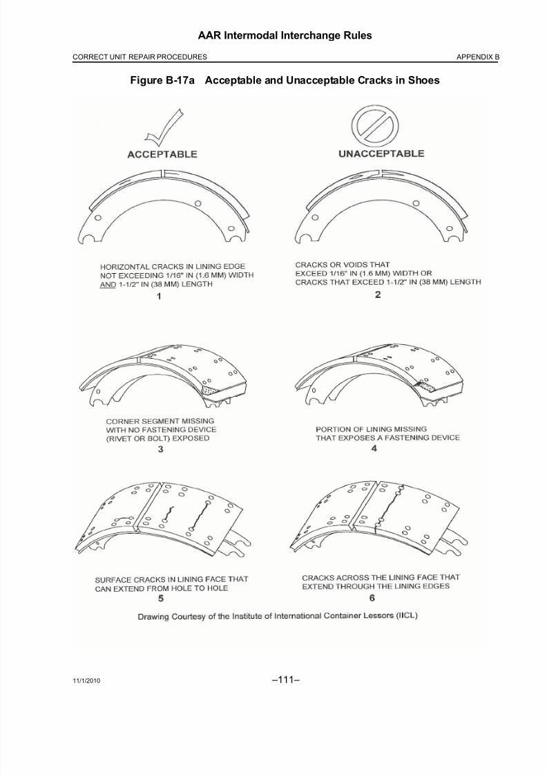
8/23/2019 AAR Intermodal Interchange Rules
http://slidepdf.com/reader/full/aar-intermodal-interchange-rules 129/224
11/1/2010 –111–
AAR Intermodal Interchange Rules
APPENDIX BCORRECT UNIT REPAIR PROCEDURES
Figure B-17a Acceptable and Unacceptable Cracks in Shoes

8/23/2019 AAR Intermodal Interchange Rules
http://slidepdf.com/reader/full/aar-intermodal-interchange-rules 130/224 –112– 11/1/2010
AAR Intermodal Interchange Rules
APPENDIX B CORRECT UNIT REPAIR PROCEDURES
B11. Upper Coupler and Kingpin
(Figure B-18 through Figure B-23)
a. Kingpin
(1) Repair Restriction
No repair to the kingpin or any trailer or chassis in intermodal service is allowed withoutnotification to the owner, and then kingpins may be repaired only in accordance withspecific instructions from the manufacturer of the trailer or chassis.
(2) Kingpin Wear Limits
By permission of the Society of Automotive Engineers, the document SAE J2228 – King Pin Wear Limits, Commercial Trailers and Semi Trailers, forms a part of this specification tothe extent specified herein. Unless otherwise specified, the current issue of this publicationshall apply. All publications are subject to revision, and the users of this document shouldbe certain they are using the current version. Copies of SAE J2228 can be obtained bycontacting the Society of Automotive Engineers, 400 Commonwealth Drive, Warrendale,PA 15096.
(a) Scope
This provision applies to upper coupler kingpins for commercial trailers and semitrailersconforming to the dimensional requirements of SAE J700 when new and originallyinstalled. The dimensions of SAE J700 are the frame of reference for this document.
(b) Purpose
The purpose of this document is to establish maximum parameters for kingpin wear, andto suggest a gauge configuration for inspecting kingpin wear. Kingpins exceeding theconditions of this specification must be removed from service and replaced.
(c) References
Applicable Document—The following publication forms a part of this specification tothe extent specified herein. The latest issue of SAE publications shall apply.
SAE Publication—Available from SAE, 400 Commonwealth Drive, Warrendale, PA15096.
SAE J700—Upper Coupler Kingpin—Commercial Trailers and Semitrailers
(d) Figure B-18 shows minimum diameters and allowable areas for wear on kingpins.Check diameter at several points around the kingpin to detect and measurenonuniform wear conditions. Kingpin wear is restricted to areas shown inFigure B-18 in crosshatch. Wear on noncrosshatched areas is not acceptable.
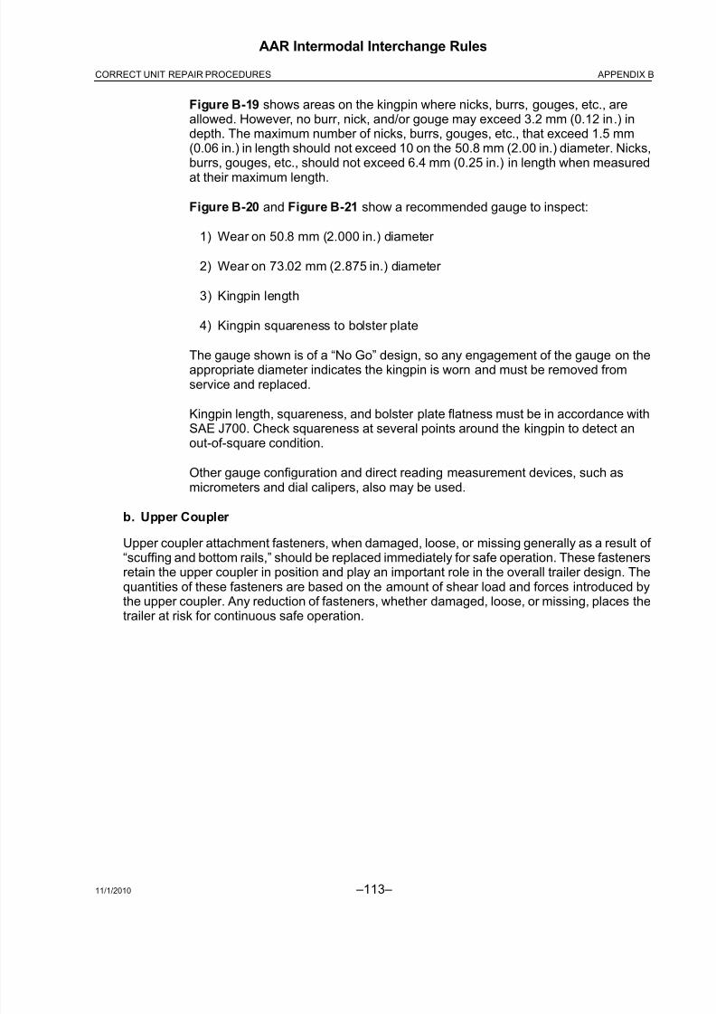
8/23/2019 AAR Intermodal Interchange Rules
http://slidepdf.com/reader/full/aar-intermodal-interchange-rules 131/224
11/1/2010 –113–
AAR Intermodal Interchange Rules
APPENDIX BCORRECT UNIT REPAIR PROCEDURES
Figure B-19 shows areas on the kingpin where nicks, burrs, gouges, etc., areallowed. However, no burr, nick, and/or gouge may exceed 3.2 mm (0.12 in.) indepth. The maximum number of nicks, burrs, gouges, etc., that exceed 1.5 mm(0.06 in.) in length should not exceed 10 on the 50.8 mm (2.00 in.) diameter. Nicks,burrs, gouges, etc., should not exceed 6.4 mm (0.25 in.) in length when measured
at their maximum length.
Figure B-20 and Figure B-21 show a recommended gauge to inspect:
1) Wear on 50.8 mm (2.000 in.) diameter
2) Wear on 73.02 mm (2.875 in.) diameter
3) Kingpin length
4) Kingpin squareness to bolster plate
The gauge shown is of a “No Go” design, so any engagement of the gauge on theappropriate diameter indicates the kingpin is worn and must be removed fromservice and replaced.
Kingpin length, squareness, and bolster plate flatness must be in accordance withSAE J700. Check squareness at several points around the kingpin to detect anout-of-square condition.
Other gauge configuration and direct reading measurement devices, such asmicrometers and dial calipers, also may be used.
b. Upper Coupler
Upper coupler attachment fasteners, when damaged, loose, or missing generally as a result of “scuffing and bottom rails,” should be replaced immediately for safe operation. These fastenersretain the upper coupler in position and play an important role in the overall trailer design. Thequantities of these fasteners are based on the amount of shear load and forces introduced bythe upper coupler. Any reduction of fasteners, whether damaged, loose, or missing, places thetrailer at risk for continuous safe operation.
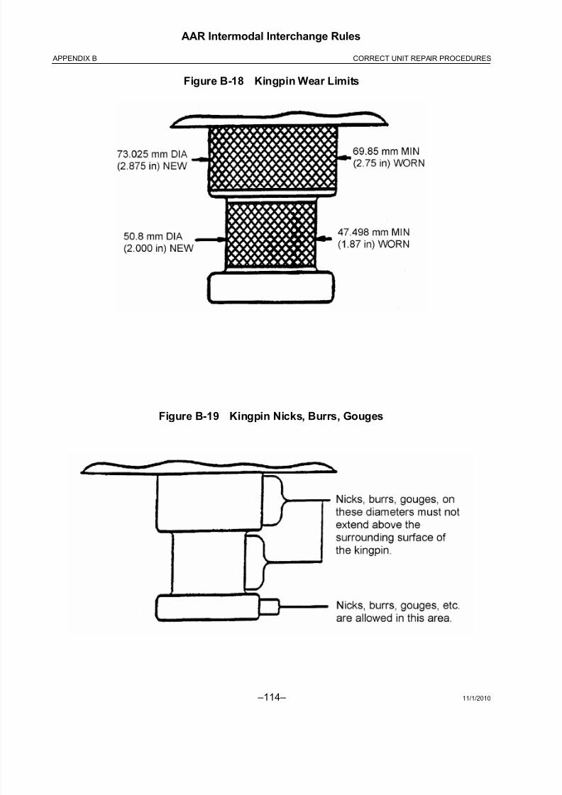
8/23/2019 AAR Intermodal Interchange Rules
http://slidepdf.com/reader/full/aar-intermodal-interchange-rules 132/224 –114– 11/1/2010
AAR Intermodal Interchange Rules
APPENDIX B CORRECT UNIT REPAIR PROCEDURES
Figure B-18 Kingpin Wear Limits
Figure B-19 Kingpin Nicks, Burrs, Gouges

8/23/2019 AAR Intermodal Interchange Rules
http://slidepdf.com/reader/full/aar-intermodal-interchange-rules 133/224
11/1/2010 –115–
AAR Intermodal Interchange Rules
APPENDIX BCORRECT UNIT REPAIR PROCEDURES
Figure B-20 Inspection of Kingpin Diameters Using One Type of Gauge
Figure B-21 Kingpin Length and Squareness Check Using One Type of Gauge
50.8 mm(2.00 in.)
50.8 mm(2.00 in.)
47.62 mm(1.87 in.)
50.65 mm(2.75 in.)
C
B
A
A = 1.250 min / 1.328 max (31.750 mm / 33.731 mm)
B = 2.704 min / 2.782 max (66.682 mm / 70.663 mm)
C = 3.256 min / 3.354 max (82.702 mm / 85.192 mm)

8/23/2019 AAR Intermodal Interchange Rules
http://slidepdf.com/reader/full/aar-intermodal-interchange-rules 134/224 –116– 11/1/2010
AAR Intermodal Interchange Rules
APPENDIX B CORRECT UNIT REPAIR PROCEDURES
Figure B-22 Front Frame
Index No. Description
1
23
4
5
6
7
8
9
10
11
12
13
Coupler Assembly, Upper
Kingpin Apron Plate
Crossmember, Front
Channel, Front Frame
Plate, Floor Front
Bulkhead Assembly
Bracket
Corner, Front, Bulkhead,
Roadside
Corner, Front, Bulkhead,
Curbside
Angle, Connection Box
SupportChannel, Front
Anti-Hook Plate

8/23/2019 AAR Intermodal Interchange Rules
http://slidepdf.com/reader/full/aar-intermodal-interchange-rules 135/224
11/1/2010 –117–
AAR Intermodal Interchange Rules
APPENDIX BCORRECT UNIT REPAIR PROCEDURES
Figure B-23 Floorbed and Frame Assembly
B12. Subassembly
(Figure B-24 and Figure B-25)
Index No. Description Index No. Description
1
2
3
4
6
79
Sill Assembly
Sill
Clip, Floor Sill
Rivet, Solid Aluminum,
Universal Head
Fifth Wheel Assembly,
Radius Front, 36 in.
KingpinStiffener
10
13
14
15
16
17
18
Crossmember
Stiffener
Plate, Pickup
Corner Radius, Curbside
Corner Radius, Roadside
Plate, Side
Plate, Bottom
Plate, Top

8/23/2019 AAR Intermodal Interchange Rules
http://slidepdf.com/reader/full/aar-intermodal-interchange-rules 136/224 –118– 11/1/2010
AAR Intermodal Interchange Rules
APPENDIX B CORRECT UNIT REPAIR PROCEDURES
a. Locking Mechanisms
(1) Types
Siding undercarriages fall into one of three categories with regard to the manner in which
they are locked into place beneath the trailer or chassis:
(a) Retractable pins operated by a pull handle or level on the slider
(b) Removable stop bars, one located in front, and one located in back of the slider
(c) A combination of retractable pins and a removable bar
(2) Safety Requirement
Regardless of the type of locking mechanism used, retractable pins and removable barsare the principal structural elements holding the slider in place beneath the trailer or chas-
sis. If these are not maintained in proper working order, or if they are not utilized in themanner prescribed by the manufacturer, the slider can become detached from the trailer or chassis, and a serious accident can result.
b. Guide and Hold-Down Brackets
All guide and hold-down brackets must be in place and in good repair for safe operation. Thesebrackets provide all or part of the lateral and vertical retention of the slider, and their maintenance is required for safe operation of the trailer or chassis.
c. Maintenance
(1) Perform scheduled maintenance of the suspension and slider per the manufacturer’s
recommendation.
(2) Perform repeat examination of all components, especially the removable stop bar and/or locking pin mechanisms, on a regular basis during preventive maintenance or safetyinspections.
(3) Replace worn or broken components with factory-approved replacement parts.
WARNING: Failure to check for proper locking pin engagement prior to driving away and failure totake proper preventive maintenance measures can lead to slider malfunction andpossible accident, resulting in property damage, personal injury, or even death.

8/23/2019 AAR Intermodal Interchange Rules
http://slidepdf.com/reader/full/aar-intermodal-interchange-rules 137/224
11/1/2010 –119–
AAR Intermodal Interchange Rules
APPENDIX BCORRECT UNIT REPAIR PROCEDURES
d. Air Rides
Air-ride suspension reduces tire wear, road wear, fuel consumption, and vibration.
System components must be maintained to prevent them from becoming damaged, worn, or
misaligned. Any abnormalities such as loose or missing fasteners, bushing connections, or abnormal tire wear should be assigned for maintenance.
Anytime parts are replaced for service, damage, wear, or failure, complete suspension shouldbe checked.
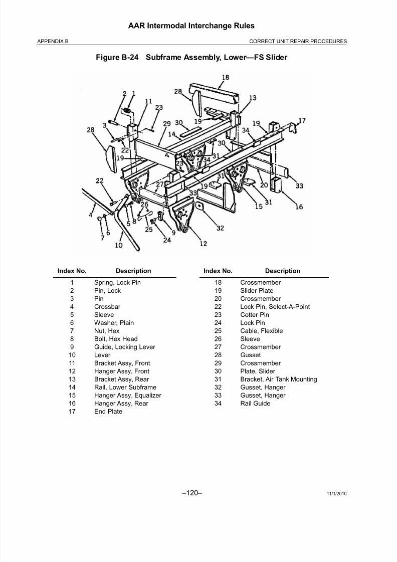
8/23/2019 AAR Intermodal Interchange Rules
http://slidepdf.com/reader/full/aar-intermodal-interchange-rules 138/224 –120– 11/1/2010
AAR Intermodal Interchange Rules
APPENDIX B CORRECT UNIT REPAIR PROCEDURES
Figure B-24 Subframe Assembly, Lower—FS Slider
Index No. Description Index No. Description
1
2
3
4
5
6
7
8
9
10
11
12
13
14
1516
17
Spring, Lock Pin
Pin, Lock
Pin
Crossbar
Sleeve
Washer, Plain
Nut, Hex
Bolt, Hex Head
Guide, Locking Lever
Lever
Bracket Assy, Front
Hanger Assy, Front
Bracket Assy, Rear
Rail, Lower Subframe
Hanger Assy, Equalizer Hanger Assy, Rear
End Plate
18
19
20
22
23
24
25
26
27
28
29
30
31
32
3334
Crossmember
Slider Plate
Crossmember
Lock Pin, Select-A-Point
Cotter Pin
Lock Pin
Cable, Flexible
Sleeve
Crossmember
Gusset
Crossmember
Plate, Slider
Bracket, Air Tank Mounting
Gusset, Hanger
Gusset, Hanger Rail Guide

8/23/2019 AAR Intermodal Interchange Rules
http://slidepdf.com/reader/full/aar-intermodal-interchange-rules 139/224
11/1/2010 –121–
AAR Intermodal Interchange Rules
APPENDIX BCORRECT UNIT REPAIR PROCEDURES
Figure B-25 Spring Assembly
Index No. Description Index No. Description
1
2
2–4
3
4
5
6
7
8
9
10
11
12
1314
Hanger, Front Spring
Hanger, Equalizer
Hanger & Equalizer
Straddle Mount AssemblyHanger, Rear Spring
Equalizer w/Rubber Bushing
Sleeve Spacer
Hex Nut
Hex Bolt
Step Bolt
Double Washer with Lock Tab
Top Plate (for round/square
U-bolt)
Torque Arm, Adjustable
Torque Arm, Non-Adjustable
Torque Arm BoltFlange Locknut
15
16
17
1819
20
21
A
B
C
D
E
F
G
Spring Seat (Round or Square)
Bottom Plate (Round or Square)
Flat Washer
Hex BoltU-Bolt (Round or Square)
Spring Assembly
(Single/Multiple Leaf)
Spring Seat (Round or Square)
Eye End, Adj. Torque Arm L.H.
Eye End, Adj. Torque Arm R.H.
Screw, Adj. Torque Arm
Hex Nut
Flat Washer
Hex Head Bolt
Bushing

8/23/2019 AAR Intermodal Interchange Rules
http://slidepdf.com/reader/full/aar-intermodal-interchange-rules 140/224 –122– 11/1/2010
AAR Intermodal Interchange Rules
APPENDIX B CORRECT UNIT REPAIR PROCEDURES
B13. Electrical and Air Systems
a. Electrical System
(1) Lighting System
(a) Lighting systems shall be 12-volt design with conventional seven-conductor electrical connector socket wires and be installed per Figure 1.
(b) The lighting system on trailers consists of a light connection located on the nose of the trailer, four red marker lights, two amber marker lights, four amber reflectors, twored reflectors, two combination stop and tail lights, one R.H. directional signal, oneL.H. directional signal, one license plate light, auxiliary lights, and all the necessarywiring, wiring clips, terminals, and connectors for the correct functioning of thesystem to meet required Federal Motor Vehicle Safety Standard 108. Lights arerecessed for protection from trailer sides and ends, with no opening permitted thatwill allow water into the system.
(c) Chassis lights consist of two combination stop and tail lights, one R.H. directionalsignal, one L.H. directional signal, and one license plate light. Lights are recessedfor protection with no opening permitted that will allow water into the system.
(2) Protective Coating
It is recommended that dielectric grease be used as a protective coating on all electricalconnectors to ensure longevity and performance of the electrical connection.
(3) Welding
Welding on trailers and chassis can be hazardous to sensitive electrical components suchas lights. Before welding, check the following:
(a) All air lines are protected from heat and splatter.
(b) All anti-skid components are shielded and protected from heat and splatter.
(c) A ground clamp is placed as close to the weld as practical.
(d) Electrical trailer power cord must be disconnected from power unit.

8/23/2019 AAR Intermodal Interchange Rules
http://slidepdf.com/reader/full/aar-intermodal-interchange-rules 141/224
11/1/2010 –123–
AAR Intermodal Interchange Rules
APPENDIX BCORRECT UNIT REPAIR PROCEDURES
b. Air System
(Figure B-26 and Figure B-27)
Air brake lines are designed to be accessible from the exterior of the trailer, normally running in
the center of the trailer, accessible from beneath. Caution should be taken when working on thefloor, crossmembers, etc., so as not to damage the integrity of the system.
WARNING: Air chamber diaphragm replacement is not recommended.
(1) Air Relay Valve Replacement
If relay valves require replacement as a result of corrosion or mechanical damage ontrailers or chassis, replacement should be on a one-for-one basis with the OEMreplacement. Do not install a relay valve that has a different manufacturer than the valveoriginally installed. Refer to the manufacturer for information on replacement valves.
(2) Drain Cock Manual Replacement
All air tanks have at the lower-most point a threaded boss and a manual rotating type valve,which allows bleeding air pressure and entrapped moisture, dirt, and debris from the tank.These valves, due to their constant exposure to moisture, do malfunction and are replacedwith a similar type rotating valve by merely unthreading the defective valve and inserting areplacement component.
(3) Glad Hand Placement
Glad hands shall be mounted in the recessed portion of the nose of the trailer or chassis
so as to make the glad hands flush or recessed, to prevent damage from impact to the noseof the trailer or chassis.

8/23/2019 AAR Intermodal Interchange Rules
http://slidepdf.com/reader/full/aar-intermodal-interchange-rules 142/224 –124– 11/1/2010
AAR Intermodal Interchange Rules
APPENDIX B CORRECT UNIT REPAIR PROCEDURES
Figure B-26 Air Connections
Index No. Description
1
2
3
4
5
6
7
8
9
Box, Light Receptacle
Coupling, Air, Service
Glad Hand
Fitting, 45 Deg. Y-Bend
Receptacle, 7-Way
Pig Tail
Nut, Retainer Speed Clip
Coupling, Air, Emergency
Glad Hand
Hose Assembly
Coupling Assembly, Airline

8/23/2019 AAR Intermodal Interchange Rules
http://slidepdf.com/reader/full/aar-intermodal-interchange-rules 143/224
11/1/2010 –125–
AAR Intermodal Interchange Rules
APPENDIX BCORRECT UNIT REPAIR PROCEDURES
Figure B-27 Air Actuation Brake System
Index No. Description
1
3
5
12
13
15
16
25, 26, 27
30
31
Service Reservoir
Valve
Valve
Tubing
Tubing
Spring Brake Chamber
Slack Adjuster
Hose Assembly
Conduit
Service Reservoir

8/23/2019 AAR Intermodal Interchange Rules
http://slidepdf.com/reader/full/aar-intermodal-interchange-rules 144/224 –126– 11/1/2010
AAR Intermodal Interchange Rules
APPENDIX B CORRECT UNIT REPAIR PROCEDURES
B14. Tires
a. Safety Precautions
When working with tires, several safety precautions should be followed. Listed below are items
to be considered:
(1) Do not reinflate a tire that has been run while flat without first inspecting the tire, rim,and wheel assembly. A tire that is 20% under-inflated is considered flat. Tire should beinspected for defects. Double-check the lock ring for damage; make sure it is secure inthe gutter before inflation.
(2) Always exhaust all air from both tires of a dual assembly prior to removing any rimcomponents or any wheel components, such as nuts and rim clamps. Make sure youremove the valve core and exhaust all air from the tires.
(3) Always stand to one side when you apply air pressure to the tire.
(4) Check rim components periodically for fatigue cracks. Replace all cracked, badly worn,damaged, severely rusted, or welded components. Three-piece rims are prohibited.
(5) Make sure that the correct parts of a tire/rim assembly are being assembled. Mixingparts of one manufacturer’s rims with those of another is prohibited.
(6) Double-check to make sure all components are properly seated prior to inflating a tire.
(7) Do not overload rims or overinflate tires. (Check with the rim manufacturer if specialoperating conditions are required.)
(8) Do not seat rings by hammering while the tire is inflated. Do not hammer on an inflatedor partially inflated tire/rim assembly.
(9) Do not inflate any tire before all side and lock rings are in place. Check components for proper assembly again after inflating to approximately 5 psi.
(10) Never sit on or stand in front of a tire and rim assembly that is being inflated. Use aclip-on chuck, and make sure the air hose is long enough to permit the person inflatingthe tire to stand to the side of the tire (minimum 24 in.).
(11) All studs and lug nuts should be replaced according to DOT regulations.
CAUTION: Always inflate tires that have been removed from trailers and chassis in a safetycage. Tires may be inflated and deflated while on the trailer or chassis.

8/23/2019 AAR Intermodal Interchange Rules
http://slidepdf.com/reader/full/aar-intermodal-interchange-rules 145/224
11/1/2010 –127–
AAR Intermodal Interchange Rules
APPENDIX BCORRECT UNIT REPAIR PROCEDURES
b. Inflation
Tires should be properly inflated according to the individual tire’s standards.
(1) Underinflation of tires causes abnormal wear at the sides of the tread because the outer
edges of the tire carry the load while the center tends to flex up away from the road.This causes the tire to run hotter.
(2) Overinflation of tires causes abnormal wear in the center of the tread, also shorteningthe life of the tire because the center of the tire tread carries more than its share of theload.
c. Slid Flat Tires
If the affected area does not extend below 2/32 inches of tread, tires should be re-matched toposition affected areas 180° from each other. When affected areas cannot be positioned 180°from each other, the tires should be replaced.
d. Minimum Standard for Retreading and Repairing Bias Ply Tires
(1) Purpose
The retreading standards described herein provide guidelines for manufacturing retreadedtrailer or chassis tires for highway service.
(2) Scope
These standards cover definitions of terms used in the retreading industry, initial inspectioncriteria for rejection of casings, acceptance criteria for repair of tires for retreading,in-process rules, and final inspection.
(3) Definitions
See Appendix C, Glossary.
(4) Casing Inspection and Selection for Retreading
(a) Inspection of Casings
A careful inspection shall be made by a skilled operator and shall include placing the tireon a bead spreader under adequate lighting (at least 200 footcandles) so that the interior and exterior of the tire are adequately exposed for visual and manual examination.
(b) Inspection Standards for Tires Used on the Highway
All casings must be top quality 12/14 ply, Department of Transportation approved, or Japanese casings that are also acceptable. No tires to be accepted for retreading maycontain any of the following weaknesses or injuries or require section repairs.
1) External
a) Ply separation
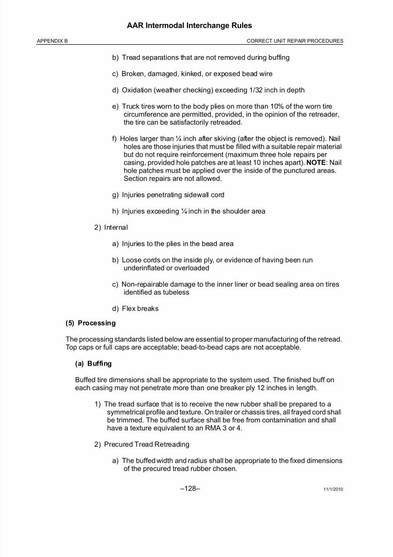
8/23/2019 AAR Intermodal Interchange Rules
http://slidepdf.com/reader/full/aar-intermodal-interchange-rules 146/224 –128– 11/1/2010
AAR Intermodal Interchange Rules
APPENDIX B CORRECT UNIT REPAIR PROCEDURES
b) Tread separations that are not removed during buffing
c) Broken, damaged, kinked, or exposed bead wire
d) Oxidation (weather checking) exceeding 1/32 inch in depth
e) Truck tires worn to the body plies on more than 10% of the worn tirecircumference are permitted, provided, in the opinion of the retreader,the tire can be satisfactorily retreaded.
f) Holes larger than ¼ inch after skiving (after the object is removed). Nailholes are those injuries that must be filled with a suitable repair materialbut do not require reinforcement (maximum three hole repairs per casing, provided hole patches are at least 10 inches apart). NOTE: Nailhole patches must be applied over the inside of the punctured areas.Section repairs are not allowed.
g) Injuries penetrating sidewall cord
h) Injuries exceeding ¼ inch in the shoulder area
2) Internal
a) Injuries to the plies in the bead area
b) Loose cords on the inside ply, or evidence of having been rununderinflated or overloaded
c) Non-repairable damage to the inner liner or bead sealing area on tires
identified as tubeless
d) Flex breaks
(5) Processing
The processing standards listed below are essential to proper manufacturing of the retread.Top caps or full caps are acceptable; bead-to-bead caps are not acceptable.
(a) Buffing
Buffed tire dimensions shall be appropriate to the system used. The finished buff on
each casing may not penetrate more than one breaker ply 12 inches in length.
1) The tread surface that is to receive the new rubber shall be prepared to asymmetrical profile and texture. On trailer or chassis tires, all frayed cord shallbe trimmed. The buffed surface shall be free from contamination and shallhave a texture equivalent to an RMA 3 or 4.
2) Precured Tread Retreading
a) The buffed width and radius shall be appropriate to the fixed dimensionsof the precured tread rubber chosen.

8/23/2019 AAR Intermodal Interchange Rules
http://slidepdf.com/reader/full/aar-intermodal-interchange-rules 147/224
11/1/2010 –129–
AAR Intermodal Interchange Rules
APPENDIX BCORRECT UNIT REPAIR PROCEDURES
b) The tires shall be prepared and shaped to a specification to be posted inthe shop.
(b) Cementing
1) Cementing must be accomplished as soon as possible, within a maximum of 12 hours after buffing.
2) Buffed casings stored over 12 hours shall be reworked prior to cementing.
3) Tires to be cemented must be free from foreign material such as buffing dust,dirt, loose cords, etc.
4) Some procedures do not require cementing of tires. In these cases, tires shallbe built or reworked within the time frames given in (b) 1) and (b) 2) ,above.
(c) Building
1) If tire cord is exposed on any portion of the buffed area, it shall be coated witha heavy-duty vulcanizing cement and then covered with a suitable materialbefore applying the tread rubber.
2) Skives shall be filled with a repair material that is thoroughly stitched or extruded into place to eliminate all trapped air and be reinforced if necessary.Buzz-outs may not exceed ½ inch long by ¾ inch wide and may not penetratemore than two breakers. Section repairs are not allowed.
3) Uncured Tread Retreading
a) Tread rubber must be of the crown, base, and gauge dimensions asrequired for matrix design, be the size in which the tire is to be cured,and shall provide a minimum of 2/32 inch (1.587 mm) replacementundertread. The minimum tread depth shall be 11/32 inch.
b) Tread rubber adhesive surfaces (if any) must not be contaminated in anyway.
c) Tread rubber must be centered around the buffed circumference of thetires, ±1/8 inch (3.175 mm).
d) Stitching (if required) must be performed in such a way as to eliminatetrapped air pockets, pulling the tread off center, and distortion of rubber shoulders, folds, and wrinkles in the rubber shoulders.
e) Splices (if any) must be made in such a manner as to ensure minimumdistortion of the rubber.
f) No more than three spot repairs per casing is permitted. No spot repair may penetrate the first ply or exceed 4 square inches.

8/23/2019 AAR Intermodal Interchange Rules
http://slidepdf.com/reader/full/aar-intermodal-interchange-rules 148/224 –130– 11/1/2010
AAR Intermodal Interchange Rules
APPENDIX B CORRECT UNIT REPAIR PROCEDURES
4) Precured Thread Retreading
a) Tread rubber must be centered around the buffed circumference of thetires, ±1/8 inch (3.175 mm).
b) Thread pattern interruption must be minimized at the splice.
c) Cut ends must have a buffed texture over the entire surface and be freeof contaminants.
(d) Curing
1) Uncured Tread Retreading
a) Tires shall be stored in such a manner as to prevent distortion of theuncured rubber and shall be kept free from contamination.
b) Information or specifications on curing time, temperature, pressure, andproper curing of tubes and rims (when used) shall be posted.
2) Precured Tread Retreading
a) Envelopes, diaphragms, or outside steam bags shall be leak-free.
b) Information or specifications on curing time, temperature, pressure, andproper curing of tubes and rims (when used) shall be posted.
c) Wicking (when required) shall be accomplished to allow air removal frombetween the envelope, diaphragm, or outside steam bags on the
enclosed tire areas during cure.
(6) Final Inspection
After curing, the retreader shall make a final examination of the tire.
(a) The inside of the tire shall be checked to ensure that nail holes, reinforced skives,section repairs, and spot repairs are properly bonded.
(b) The retreaded tire shall not be buckled and shall show no separations.
(c) The outside of the tire shall be checked to ensure that it has been adequately
molded and cured and has all the required labeling. The retread manufacturers’complete DOT code (including retreader identification and date) must be molded/branded into the sidewall of the original casing and be visible after capping. (No coldvulcanizing cement is allowed.)
(7) Finished Product
(a) The finished product must be serviceable for interstate highway use.
(b) The finished product must be warranted by the manufacturer to either the purchaser or trailer/chassis/tire owner.

8/23/2019 AAR Intermodal Interchange Rules
http://slidepdf.com/reader/full/aar-intermodal-interchange-rules 149/224
11/1/2010 –131–
AAR Intermodal Interchange Rules
APPENDIX BCORRECT UNIT REPAIR PROCEDURES
B15. DOT Underride Guard
DOT underride guards are assemblies required by DOT specifications that are fastened to rear sillassemblies and/or slider rails and designed to reduce damage in rear-end collisions (refer toFMVSS 223 and FMVSS 224).
a. A vertical bend in excess of 3 inches in the horizontal member should be repaired.
b. If the end of the horizontal member is bent upward, it can be bent down to its originalposition. If it is bent downward, it can be left alone or bent up to its original position. If it isbent forward less than 3 inches, no repair is needed.
c. If the middle of the horizontal member is bent forward, or if the entire guard is bent forward,consult the manufacturer for repair guidelines.
d. Use only cold bending methods. Repetitive bending should be avoided.
e. With guard damage, the rear crossmembers, rear sill, vertical members, and the last 6 feetof the floor also must be inspected for damage.
f. Missing guards should be replaced with an OEM assembly or an assembly fabricated to thesame specifications.

8/23/2019 AAR Intermodal Interchange Rules
http://slidepdf.com/reader/full/aar-intermodal-interchange-rules 150/224 –132– 11/1/2010
AAR Intermodal Interchange Rules
APPENDIX B CORRECT UNIT REPAIR PROCEDURES
THIS PAGE LEFT BLANK INTENTIONALLY

8/23/2019 AAR Intermodal Interchange Rules
http://slidepdf.com/reader/full/aar-intermodal-interchange-rules 151/224
11/1/2010 –133–
AAR Intermodal Interchange Rules
APPENDIX CGLOSSARY
APPENDIX C
GLOSSARY
The following terms when used in this Standard shall have the meaning set forth.
C1. General Terms
RECORDED IMAGE— A high-resolution photograph or video.
C2. Trailer Component Glossary (page 1 of 4)
(Refer to Figure C-1 and Figure C-2)
AIR BRAKE SYSTEM— A brake system that uses compressed air as the means of transmittingpressure or force from driver control to service brakes.
ANTILOCK SYSTEM—That part of a service brake system that automatically controls the degreeof rotational wheel slip at one or more wheels during braking.
AXLE— A beam with spindles about which wheels rotate.
AXLE SPINDLE—The machined steel rod or shaft (usually heat-treated and hardened) at each endof the axle that is contoured to accept wheel bearings, and around which the wheels rotate.
BRAKE CHAMBER—Converts differential air pressures into mechanical forces that are applied towheel brakes through mechanical linkage. (Also called “air chamber,” “vacuum chamber,” “cans,”“boosters,” “air brake chamber,” “vacuum-brake chamber,” “vacuum boosters.”)
BRAKE SPIDER—The center plate, either bolted or welded to the axle, to which the brakeassembly is attached.
BULKHEAD— A structure used to protect against damage caused by shifting cargo and/or toseparate loads.
BUMPER— A structure designed to provide rear-end protection. Also called DOT underride guard.
CARGO CONTROL TRACK— A vertical or horizontal structural member, normally attached tosidewall posts or flooring, with pierced slots for use with cargo tie-off straps or double-deckingcomponents or other restraining devices.
CERTIFICATE HOLDER— A moisture-proof container provided for storage and easy access totrailer-related literature such as licenses, registration, defect and maintenance information. (Alsocalled “Registration Holder” and “Defect Card Holder.”)
CERTIFICATION LABEL (NATIONAL HIGHWAY TRAFFIC SAFETY ADMINISTRATION)— Alabel permanently affixed to forward left side of the trailer stating that the vehicle conforms to allapplicable Federal Motor Safety Standards in effect on the date of original manufacture.
CLEARANCE LAMPS—Lamps mounted on the floor, rear, and sides of a vehicle that indicate itsoverall length and width.

8/23/2019 AAR Intermodal Interchange Rules
http://slidepdf.com/reader/full/aar-intermodal-interchange-rules 152/224 –134– 11/1/2010
AAR Intermodal Interchange Rules
APPENDIX C GLOSSARY
CONNECTION BOX—Contain fittings for trailer emergency and service brake connections and
electrical connector to which the lines from the towing vehicle may be connected. (Also called“junction box,” “light box.”)
CONVERTER DOLLY— A component with a fifth wheel lower half or equivalent mechanism; theattachment that allows other units to be added.
CROSSMEMBER— A structural member attached to the bottom side rails that support the floor.(Also called “bolster,” “sill,” “beam.”)
CUBIC CAPACITY—Useful internal load-carrying space usually expressed in cubic feet, cubicyards, or U.S. gallons. (Also referred to as “available cube.”)
CURBSIDE (RIGHT SIDE)—[ROADSIDE (LEFT SIDE)] Viewing the trailer from the rear, the
curbside is right and roadside is left. The terms to be used on repair orders are right and left side.
DOLLY WHEELS— A set of steel wheels that serve as ground contact for support of the trailer.( Also see Sand Shoe)
DOOR HEADER—Horizontal (structural) framing member over a door opening. (Also known as the“rear header.”)
DOOR HINGE— A device that secures the door to the trailer frame, allowing the door to turn or move.
DOOR HOLD BACK—The device used to hold doors in the open position. Normally madetwo-piece, male and female, with one part attached to the door and the other to the side of the
trailer. (Also referred to as “tie-backs.”)
DOOR SILL—Horizontal frame member at bottom of a door opening.
ELECTRICAL CONNECTOR (7-WAY ELECTRICAL CONNECTOR SOCKET)— A receptacledesigned to accept truck tractor electrical cable plugs.
FIFTH WHEEL— A device mounted on a truck tractor or a converter dolly that mates with and pivotswithin the lower coupler of a truck tractor or converter dolly while coupling the two units together.
GLAD HANDS—Fittings for connection of air brake lines between vehicles. Vacuum brake hoseconnectors are also called “hose couplings.”
GROMMET— A device that serves as a support and protection to that which passes through it.
GROSS AXLE WEIGHT RATING (GAWR)—The rated capacity at the tire-ground interface;reflects the “weakest link” in the entire suspension system, whether it be the springs, axles, wheels,rims, or tires.
GROSS VEHICLE WEIGHT RATING (GVWR)—The GVWR for semitrailers is the sum of the trailer tare weight and that uniformly distributed payload that will result in a suspension load at thetire-ground interface equal to the sum of the trailer’s gross axle weight ratings (GAWR), with alimitation imposed by practical or structural considerations.
GROSS WEIGHT—The weight of a trailer together with the weight of its entire contents.
C2. Trailer Component Glossary (page 2 of 4)
(Refer to Figure C-1 and Figure C-2)

8/23/2019 AAR Intermodal Interchange Rules
http://slidepdf.com/reader/full/aar-intermodal-interchange-rules 153/224
11/1/2010 –135–
AAR Intermodal Interchange Rules
APPENDIX CGLOSSARY
IDENTIFICATION LAMPS—Lamps used to identify front, rear, and side of trailers, as specified by
the Federal Motor Vehicle Standard 108.INTERIOR LINING (PLYWOOD LINERS/PLY-LINERS)—Materials used in the interior of trailers toprotect side panels, roof bows, and posts.
KINGPIN— Attaching pin on a semitrailer that mates with the pivots within the lower coupler of atruck tractor or converter dolly while coupling the two units together.
LIFT PADS—Protective hardware affixed to lower side rails of a TOFC trailer to distribute stressesduring trailer lifting and handling operations.
MANIFEST BOX— A moisture-proof container used for storage of important documents; usuallylocated on the nose of the trailer.
PANEL— A section of material used to cover the exterior of a trailer.
PICK-UP PLATE— A plate structure located forward of the kingpin and terminating at theapproximate front of the vehicle; designed for initial contact with the fifth wheel during coupling.
POST—Vertical structural member to which panels and sometimes doors are attached.
REAR CROSSMEMBER (SILL)—The horizontal member at the extreme rear of the trailer normallyused to mount rear bumpers and stop, turn, and tail lights.
REAR DOORS—Hinged structures provided at the rear of the trailer to allow access to the cargoarea when opened.
REFLECTOR—Material permanently fixed on a vehicle to reflect the light from all sources, butprimarily from the head lamps of an approaching motor vehicle.
RIM— A metal support for a tire or a tire and tube assembly, upon which the tire beads are seated.
ROADSIDE (LEFT SIDE)—see Curbside (Right Side)
ROOF BOW— An interior structural member attached to both top side rails.
RUB RAIL— A rail extending horizontally along the exterior of a trailer sidewall, or along thelongitudinal edge of a platform trailer, intended as crush protection for less rigid components of trailers frequently operated in close quarters.
RUNNING LIGHTS—Marker, clearance, and identification lights; required by regulations.
SAND SHOE— A flat steel plate that serves as ground contact for support of the trailer. ( Also see Dolly Wheels)
SCUFF LINER— A strip installed along the lower inside of a trailer to protect the lining, side panels,or posts from wear or damage.
SIDE RAILS, LOWER—The main longitudinal frame member located at the lower edge of thetrailer to connect the side wall and floor structures.
C2. Trailer Component Glossary (page 3 of 4)
(Refer to Figure C-1 and Figure C-2)

8/23/2019 AAR Intermodal Interchange Rules
http://slidepdf.com/reader/full/aar-intermodal-interchange-rules 154/224 –136– 11/1/2010
AAR Intermodal Interchange Rules
APPENDIX C GLOSSARY
SIDE RAILS, UPPER—The main longitudinal frame member used to connect the roof and the side
wall structures.SLACK ADJUSTER— Adjustable mechanical lever used to transmit brake chamber force to thebrake camshaft when brakes are applied. Slack adjusters are designed to compensate for brakelining wear.
SLIDING UNDERCARRIAGE— An undercarriage with a subframe that allows fore-and-aftadjustment of its location on the trailer; used to shift a greater part of the gross load onto the kingpinor the suspension. (Sometimes referred to as a “slider.”)
SUPPORTS—Devices generally adjustable in height, used to support the front end of a semitrailer in an approximately level position when disconnected from a towing vehicle. (Also referred to as“landing gears,” “props,” “dollies,” “legs.”)
TANDEM AXLE— A two-axle assembly with an equalizing means for transferring weight betweenaxles.
TOFC— Abbreviation for “trailer-on-flatcar.” (Also referred to as “piggyback.”)
TOFC PLATE— A plate structure extending approximately 24 inches rearward of the upper coupler plate that offers protection during coupling and uncoupling to the flatcar stanchion. (Also referred toas “G-85 plate”, “flatcar extension plate,” “kick plate.”)
UNDERCARRIAGE—Complete sub-frame, suspension with one or more axles that may beinterconnected, and wheels, tires and brakes. (Also referred to as “bogie” or “running gear.”)
UPPER COUPLER ASSEMBLY—Upper coupler plate, reinforcement framing, and fifth-wheelkingpin mounted on a semitrailer. (Also referred to as “upper fifth wheel assembly.”)
UPPER COUPLER PLATE— A plate structure through which the kingpin neck and collar extend.The bottom surface of the plate contacts the fifth wheel when the trailer is coupled. (Also referred toas “fifth wheel plate.”)
C2. Trailer Component Glossary (page 4 of 4)
(Refer to Figure C-1 and Figure C-2)
8/23/2019 AAR Intermodal Interchange Rules
http://slidepdf.com/reader/full/aar-intermodal-interchange-rules 155/224
11/1/2010 –137–
AAR Intermodal Interchange Rules
APPENDIX CGLOSSARY
C3. Container Component Glossary (page 1 of 2)
COFC— Abbreviation for container-on-flatcar.
COLLAPSIBLE FREIGHT CONTAINER—Freight container of rigid construction, the major
components of which can easily be folded or disassembled and then reassembled. (Also referredas “flat rack.”)
CONTAINER— A unit of transport equipment that is
a. of a permanent character and strong enough for repeated use.
b. specially designed to facilitate the carrier of goods by one or more modes of transportwithout intermediate reloading.
c. fitted with devices permitting its ready handling, particularly its transfer from one mode toanother.
The term “container” does not include vehicles or conventional packing. (Also referred to as “freightcontainer,” “cargo container,” “intermodal container.”)
CONTAINER CHASSIS— A frame equipped with wheels, landing gear, and kingpin assembly,excluding floor, sides, and roof, and with locking devices for securing and transporting a container as a wheeled vehicle.
CONTAINER DISPLACEMENT—The outside cubic volume of the container.
CORNER FITTINGS—Fittings located at the eight corners of the container that provide means for handling, stacking, and securing the container. (May also be called “corner castings.”)
CORNER STRUCTURES/POST—Vertical frame components located at the four corners of the
container, integral with the corner fittings, and connecting the roof, floor, and wall structures of closed containers, or the wall and floor structures of an open top container.
CROSSMEMBERS—Structural members attached to the bottom side rails that support the floor.(Also called “bolster,” “sill,” or “beam.”)
CUBIC CAPACITY—Useful internal load-carrying space, usually expressed in cubic feet, cubicyards, or U.S. gallons. (Also referred to as “available cube.”)
DOOR HEADER—Horizontal (structural) framing member over a door opening. (Also known as the“rear header.”)
DOOR SILL—Horizontal frame member at bottom of a door opening.
END DOOR—Weather-tight movable swinging structure to provide access to the cargo space.
END WALL— Assembly surrounded by the end frame and wall at either end of the container.
FLOOR—The cargo-carrying surface of the container. (Also referred to as “deck.”)
FORK POCKETS—The structural openings or sleeves in the base of the container that permit entryof fork lift devices.
GROSS WEIGHT—The allowable total weight of the container and cargo, exclusive of the chassis.
8/23/2019 AAR Intermodal Interchange Rules
http://slidepdf.com/reader/full/aar-intermodal-interchange-rules 156/224 –138– 11/1/2010
AAR Intermodal Interchange Rules
APPENDIX C GLOSSARY
INTERFACE SUPPORTS (KNEE BRACE)—Structural reinforcements of a prescribed square areawithin a designated location on the underside of the container. It is designed to provide intermediatesupport points when the loaded container is being transported on a chassis.
TARE WEIGHT—Weight of the empty freight container, including its normal complement of ladingrestraint devices.
TWIST LOCK— A mechanically operated device located on the corners of a container chassis andon automatic lifting spreaders, used for securing a container during transport or transfer.
C3. Container Component Glossary (page 2 of 2)

8/23/2019 AAR Intermodal Interchange Rules
http://slidepdf.com/reader/full/aar-intermodal-interchange-rules 157/224
11/1/2010 –139–
AAR Intermodal Interchange Rules
APPENDIX CGLOSSARY
C4. Tire Glossary (page 1 of 4)
(Refer to Figure C-3 and Figure C-4.)
BASE WIDTH—That portion of the tread rubber that joins to the buffed surface of the worn tire.
BEADS—the anchoring part of the tire that is shaped to fit the rim. Made of high-tensile steel wireswrapped and reinforced by the plies.
BEAD SEALING AREA—The flat area and heel area of the bead that contacts the rim. Withtubeless tires, the bead area seals to the rim flange to retain air.
BELTED BIAS TIRES—Tires constructed so the ply cords extending from bead to bead lie atalternate angles substantially less than 90° to the centerline of the tread. On top of the body pliesare two or more belt plies extending approximately from shoulder to shoulder, runningcircumferentially around the tire at alternate angles.
BIAS PLY TIRES—Tires constructed so the ply cords extend from bead to bead and are laid at
alternate angles substantially less than 90° to the centerline of the tread.
BODY PLIES—Layers of rubber-coated parallel cords extending from bead to bead.
BREAKS (CRACKS)— A surface opening extending into or through the plies.
Flex Breaks— A break into or through one or more plies, usually parallel to the beads.
Impact Breaks— A star or X-shaped or diagonal break into or through plies, usually visible fromthe inside of the tire.
Radial Crack— A crack in the outer surface of the tire, usually in the sidewall area proceedingperpendicularly to the bead.
Tread Cracks (channel or groove)—Cracks in the base of the tread grooves or voids.
BUCKLED— Any gross distortion of the tire body or tread area evidenced by wrinkling on the insideof the casting.
BUFFED CONTOUR—The shape of the buffed tire that usually includes a specified radius andwidth.
BUFFED RADIUS— A measure of the buffed surface curvature from shoulder to shoulder.
BUFFED TEXTURE—That surface produced by buffing, rasping, or cutting as defined by TheRubber Manufacturers Association Buffed Textures (RMA Shop Bulletin No. 29.)
CASING—The complete tire structure.
CEMENT— An adhesive compound used to provide building tack. May be brushed or sprayed onthe buffed surface.
CHECK TEMPLATE— A precut pattern used to determine the contour of a buffed tire to checkcompatibility to a matrix.
CORDS—The individual strands forming the plies in a tire.
CROSS SECTION (C.S.)—The section width of a tire casing.

8/23/2019 AAR Intermodal Interchange Rules
http://slidepdf.com/reader/full/aar-intermodal-interchange-rules 158/224 –140– 11/1/2010
AAR Intermodal Interchange Rules
APPENDIX C GLOSSARY
CURE—The process of vulcanization of rubber by applying heat, pressure, and time.
CURING TUBES—Special stubs placed within the tire while curing.
DIAPHRAGM— A flexible covering used to encompass part or all of a tire during retreading in someprocesses.
ENVELOPE— A flexible covering used to encompass part or all of a tire during retreading in someprocesses.
GAUGE—Thickness, usually expressed in thirty-seconds of an inch, or by the decimal system, or inmillimeters in the metric system.
INJURY— A break or cut of any shape caused by a penetrating object or severe scuff or impact.
INJURY SIZE—Widest opening in the cord body after skiving and buffing.
INNER LINER—The tubeless tire inner surface used to retain the inflation media.
KINKED (BEADS)— A sharp permanent bend in the bead wires at one or more points around thecircumference of the bead.
LOAD RANGE—Used as letters (A, B, C, etc.) in tire identification to identify a given size tire, withits load and inflation limits, when used in a specific type of service as defined in Tire and Rim
Association Inc. (or equivalent) yearbooks.
MATRIX— Aluminum, rubber, or steel rings or segments that form the cavity in which a tire retread
is cured and with which the tread design is formed.NAIL HOLE— A penetration caused by a small, sharp object, ¼ inch maximum diameter.
PLIES—Layers of rubber-coating paralleled cords.
POSTED—Placement on the immediate premises of the retread shop, available to all personnelinvolved in the retreading operations and to the management of the shop.
PROTECTOR PLY— A ply added primarily for casing protection, which, in some cases, may beremoved during retreading.
REINFORCEMENT (REPAIR)— Any material, usually rubber and fabric, vulcanized to a tire to add
strength to the tire cord body at an injury.REPAIRING—Reconditioning of portions of tires that have been injured by punctures, cuts, breaks,cracks, etc., that restore strength for additional safe service.
REPAIR MATERIAL— Any rubber compound or patch material used to make repairs.
RETREADING—(Recapping)
Full Treading—Replacement of the worn tread with rubber extending over the shoulders.
Top Treading—Replacement of the worn tread area only.
C4. Tire Glossary (page 2 of 4)
(Refer to Figure C-3 and Figure C-4.)

8/23/2019 AAR Intermodal Interchange Rules
http://slidepdf.com/reader/full/aar-intermodal-interchange-rules 159/224
11/1/2010 –141–
AAR Intermodal Interchange Rules
APPENDIX CGLOSSARY
Bead-to-Bead Retreading—Replacement of the worn tread area and sidewall rubber
extending to the bead.Precured Tread Retreading—Replacement of the worn tread areas with pre-vulcanizedtreads containing the tread design already cured in.
SECTIONS—Repairs made to a casing where an injury larger than a nail hole extends throughmore than 75% of the plies or through the casing in the tread or sidewall areas.
SEPARATIONS—Lack of adhesion or cohesion between any adjacent materials in a tire.
TREAD SEPARATION—Pulling away of the tread from the tire body.
RETREAD SEPARATION— A separation between the tread rubber and the buffed tire casing.
PLY SEPARATION— A breakdown of the bond between components in the bead area.
BELT EDGE SEPARATION— A breakdown of the bond between components near the edge of thebelt plies.
SHOULDER—The upper sidewall area of the tire casing immediately adjacent to the tread area.
SIDEWALL—That portion of the tire casing between the bead and shoulder.
SKIVE—Removal of damaged material prior to making a repair.
SPLICE— A junction of the ends of any tire component.
SPOT (REPAIR)—The replacement of rubber in an injury that penetrates to no more than 25% of the body plies.
STITCHING— A method used to both remove trapped air and improve rubber contact for better adhesion during handling.
SURFACE REPAIR— A repair that is in the rubber portion of the casing only; to, but not throughany ply.
SYNTHETIC RUBBER—Man-made rubber.
TEXTURE—(see Buffed Texture)
TREAD—That portion of a tire that comes in contact with the road.
TREAD DESIGN—The non-skid pattern or design on the tread portion of a tire.
TREAD GROOVES—The space between two adjacent tread ribs, lugs, or bars.
UNDERTREAD (REPLACEMENT)—The rubber between the base of the tread grooves and thebuffed surface.
VULCANIZATION— A chemical reaction that takes place under appropriate time, temperature, andpressure and develops desirable tire characteristics and properties. ( Also see Cure)
C4. Tire Glossary (page 3 of 4)
(Refer to Figure C-3 and Figure C-4.)

8/23/2019 AAR Intermodal Interchange Rules
http://slidepdf.com/reader/full/aar-intermodal-interchange-rules 160/224 –142– 11/1/2010
AAR Intermodal Interchange Rules
APPENDIX C GLOSSARY
WEATHER CHECKING— A crazing or cracking of the sidewall surface of the tire attributable to an
atmospheric condition rather than to flexing.WICKING— A capillary act of air escapement from the tire casing, or from under any envelope, bymeans of fabrics or cords.
ZIPPER RUPTURE— A circumferential rupture on the sidewall flex area of a steel-cord radial tire.
C4. Tire Glossary (page 4 of 4)
(Refer to Figure C-3 and Figure C-4.)

8/23/2019 AAR Intermodal Interchange Rules
http://slidepdf.com/reader/full/aar-intermodal-interchange-rules 161/224
11/1/2010 –143–
AAR Intermodal Interchange Rules
APPENDIX CGLOSSARY
Figure C-1 Trailer Components—Front/Side
Index No. Description Index No. Description
1
2
3
4
5
6
7
8
9
10
Refrigeration Unit*
Nose Top Rail
Corner Cap (Or Casting)
Radius Panel
Side Sheet
Clearance Light
Corner Post (Rear)
Battery Box*
Registration Holder
Electrical Junction Box &
Air Connectors (Glad Hands)
11
12
13
14
15
16
17
18
19
Kingpin
Bottom Pickup Rail
Dolly (Landing) Leg
Sand Shoe or Dolly Wheels
Cross Brace
Leg Brace
Leg Mounting Gusset
Side Bottom Rail
Tandem Assembly (Bogie)
*Refrigerated Trailers Only

8/23/2019 AAR Intermodal Interchange Rules
http://slidepdf.com/reader/full/aar-intermodal-interchange-rules 162/224 –144– 11/1/2010
AAR Intermodal Interchange Rules
APPENDIX C GLOSSARY
Figure C-2 Trailer Components—Rear
Index No. Description Index No. Description
1
2
3
4
5
6
7
Door Moulding
Clearance Lights
Door Header
Corner Post
Door Hinge
Locking Bar Guide
Locking Bar Latch
8
9
10
11
12
13
14
Tail Light Assembly
Mud Flap Bracket
Locking Bar Keeper and Cam
Mud Flap
Rear Sill
DOT Underride Guard
Locking Bar Handle
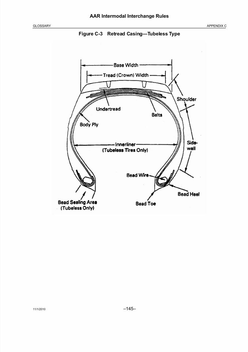
8/23/2019 AAR Intermodal Interchange Rules
http://slidepdf.com/reader/full/aar-intermodal-interchange-rules 163/224
11/1/2010 –145–
AAR Intermodal Interchange Rules
APPENDIX CGLOSSARY
Figure C-3 Retread Casing—Tubeless Type

8/23/2019 AAR Intermodal Interchange Rules
http://slidepdf.com/reader/full/aar-intermodal-interchange-rules 164/224 –146– 11/1/2010
AAR Intermodal Interchange Rules
APPENDIX C GLOSSARY
Figure C-4 Buffed Casing—Bias Tubed Type

8/23/2019 AAR Intermodal Interchange Rules
http://slidepdf.com/reader/full/aar-intermodal-interchange-rules 165/224
11/1/2010 –147–
AAR Intermodal Interchange Rules
APPENDIX DFLAT FILE FORMAT
APPENDIX D
FLAT FILE FORMAT
D1. Introduction
The new “J File” allows for the electronic exchange of damage data. The first field in each recordspecifies the document type. Based on the first field, the data can be read in the appropriatemanner. Thus, multiple damage documents can be contained in the same file. For now, only theformat of a J2 document has been specified. Future development could include specifications for other J Forms.
D2. J File Format
In the “J File,” each record is specified between ‘{‘ and ‘}’ characters. Fields within a record aredelimited by the ‘*’ character. The first field of any record is the document type. For now, onlysupport for the “J2” document type has been specified. Note: All data in the file should be read as acharacter stream. No assumptions should be made about carriage returns. That is, it should not beassumed that each document record is a new line, despite the fact that some text editors display itthis way.
D3. J2 Format
The first field of a J2 record is ‘J2.’ After the’'J2’ field, there are 21 header fields. After the header fields, multiple line items can follow. It is possible to have no line items. Each line item contains 12fields. Below is a description of the fields in the order they appear in the file. Fields marked with a ‘*’can be empty. For the header fields, the “J2 Number” field is the unique identifier. For the line itemfields, the “Damage ID” is the unique identifier.
a. Header Fields
Field Data Type
J2 Number Character String, Max 10 CharactersBureau Character String, Max 10 CharactersEntry Date Data/Time ValueInitial Character String, Max 4 CharactersNumber Long Integer, Max 231-1Equipment Type Character String, Max 10 CharactersDelivering RR Character String, Max 4 CharactersInterchange Type Character String, Max 10 CharactersReceiving RR Character String, Max 4 CharactersStation Character String, Max 50 CharactersDelivery Date Date/Time ValueLoad/Empty Single Character, ‘L’ or “E’Responsible RR Character String, Max 4 CharactersRailcar Initial*
*Field can be empty
Character String, Max 4 CharactersRailcar Number* Long Integer, Max 231-1Chassis Initial* Character String, Max 4 CharactersChassis Number* Long Integer, Max 231-1RR Issued Bit Value, 0 or 1RR Inspector* Character String, Max 50 CharactersIB Inspector* Character String, Max 50 CharactersOpen/Close Status Single Character, “O’ or ‘C’
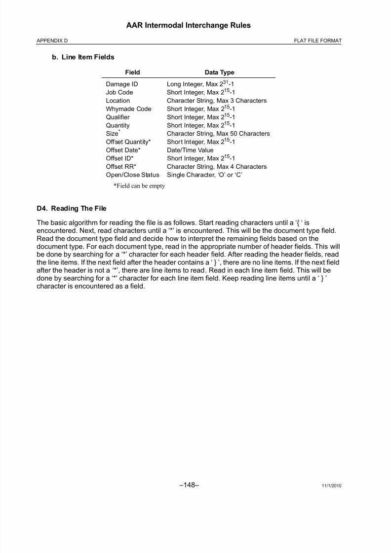
8/23/2019 AAR Intermodal Interchange Rules
http://slidepdf.com/reader/full/aar-intermodal-interchange-rules 166/224 –148– 11/1/2010
AAR Intermodal Interchange Rules
APPENDIX D FLAT FILE FORMAT
b. Line Item Fields
D4. Reading The File
The basic algorithm for reading the file is as follows. Start reading characters until a ‘{ ‘ isencountered. Next, read characters until a ‘*’ is encountered. This will be the document type field.Read the document type field and decide how to interpret the remaining fields based on thedocument type. For each document type, read in the appropriate number of header fields. This willbe done by searching for a ‘*’ character for each header field. After reading the header fields, readthe line items. If the next field after the header contains a ‘ } ’, there are no line items. If the next fieldafter the header is not a ‘*’, there are line items to read. Read in each line item field. This will bedone by searching for a ‘*’ character for each line item field. Keep reading line items until a ‘ } ’character is encountered as a field.
Field Data Type
Damage ID Long Integer, Max 231-1
Job Code Short Integer, Max 215-1
Location Character String, Max 3 Characters
Whymade Code Short Integer, Max 215-1
Qualifier Short Integer, Max 215-1
Quantity Short Integer, Max 215-1
Size*
*Field can be empty
Character String, Max 50 Characters
Offset Quantity* Short Integer, Max 215-1
Offset Date* Date/Time Value
Offset ID* Short Integer, Max 215-1
Offset RR* Character String, Max 4 Characters
Open/Close Status Single Character, ‘O’ or ‘C’

8/23/2019 AAR Intermodal Interchange Rules
http://slidepdf.com/reader/full/aar-intermodal-interchange-rules 167/224
11/1/2010 –149–
AAR Intermodal Interchange Rules
APPENDIX ESUBSCRIBERS
APPENDIX E
SUBSCRIBERS TO THE INTERMODAL INTERCHANGE AGREEMENT
E1. Railroad Companies
Arkansas, Louisiana, & Mississippi Railroad Co.Louisiana & North West Railroad Co.
Angelina & Neches River Railroad Massachusetts Central Railroad Corp.
Belfast and Moosehead Lake Railway Co. Middletown and New Jersey Railway
Boston & Maine Corporation Minnesota, Dakota & Western Railway Co.
Burlington Northern and Sante Fe Railway Co. Missouri & Northern Arkansas Railroad
Canadian National Railways New York & Atlantic Railway
Canadian Pacific Railway Norfolk Southern Railway Company
(Includes affiliates per agreement)Canton Railroad Company
Claremont Concord Railroad Corp. Paducah and Louisville Railway, Inc.
Clarendon & Pittsford Railroad Company Pattison Brothers Mississippi River Terminal
Columbus and Greenville Railway Co. Portland Terminal Company
Consolidated Rail Corporation Providence and Worcester Railroad Co.
CSX Transportation, Inc. Sand Springs Railway Company
Dakota, Minnesota & Eastern RR Southern Railway of British Columbia, Ltd.
Delta Valley & Southern Railway Co. Texas South-Eastern Railroad
East Erie Commercial Railway TFM, S.A. de C.V.
Florida East Coast Railway Company Toledo, Peoria & Western Railway Corp.
Fordyce & Princeton Railroad Co. Tyburn Railroad Company
Grafton & Upton Railroad Company Union Pacific Railroad Company
H & S Railroad Company Upper Merion & Plymouth Railroad Co.
Kankakee, Beaverville & Southern Rwy. Vermont Railway, Inc.
Kansas City Southern Railway Co. Wisconsin & Southern Railroad Co.

8/23/2019 AAR Intermodal Interchange Rules
http://slidepdf.com/reader/full/aar-intermodal-interchange-rules 168/224 –150– 11/1/2010
AAR Intermodal Interchange Rules
APPENDIX E SUBSCRIBERS
E2. Non-Railroad Companies
Advance Transportation Company Intermodal Association of North America
Agmark Foods, Inc. Intermodal Shipping Services, Inc.
Alliance Transportation, Inc. "K" Line America, Inc.
American President Lines Nippon Yusen Kaisha (NYK Line a/Agents) American Chassis Leasing Pacer
APL Limited PoleStar Transport
Atlantic Container Line Sea-Land Service, Inc. (Maersk Sealand)
Blue Star North America Ltd. Sea Star Line
Chicago Bandag, Inc. S.E. Capital Container Finance Corp.
Container Port Group, Inc. Stevens Transport
Detroit Salt Company Tank Solutions
Eagle Systems, Inc. Tire Management
Evergreen Marine Corporation Tires Services Co.
Frozen Food Express Transwest LogisticsGreenbrier Capital Corporation TTM Logistics, S.A. de C.V.
Hanjin Shipping Company, Ltd. WTL Rail Corporation
Hapag-Lloyd, A.G. XTRA Intermodal

8/23/2019 AAR Intermodal Interchange Rules
http://slidepdf.com/reader/full/aar-intermodal-interchange-rules 169/224
11/1/2010 –151–
AAR Intermodal Interchange Rules
APPENDIX FCOMPLETE MATRIX
APPENDIX F
COMPLETE MATRIX
This Appendix contains a matrix listing all valid combinations of Job Codes, Why Made Codes,
Condition Codes, and Location Codes and assigns responsibility for each such combination basedon the Rules contained in the main body of these Intermodal Interchange Rules.
Changes from the prior version of this matrix are identified in the first column, with “A” for additions,“D” for deletions, and “U” for updates.
This matrix is available as a separate download at AAR's Web site, www.aar.com.

8/23/2019 AAR Intermodal Interchange Rules
http://slidepdf.com/reader/full/aar-intermodal-interchange-rules 170/224
–152– 11/1/2010
AAR Intermodal Interchange Rules
APPENDIX F COMPLETE MATRIX
THIS PAGE LEFT BLANK INTENTIONALLY
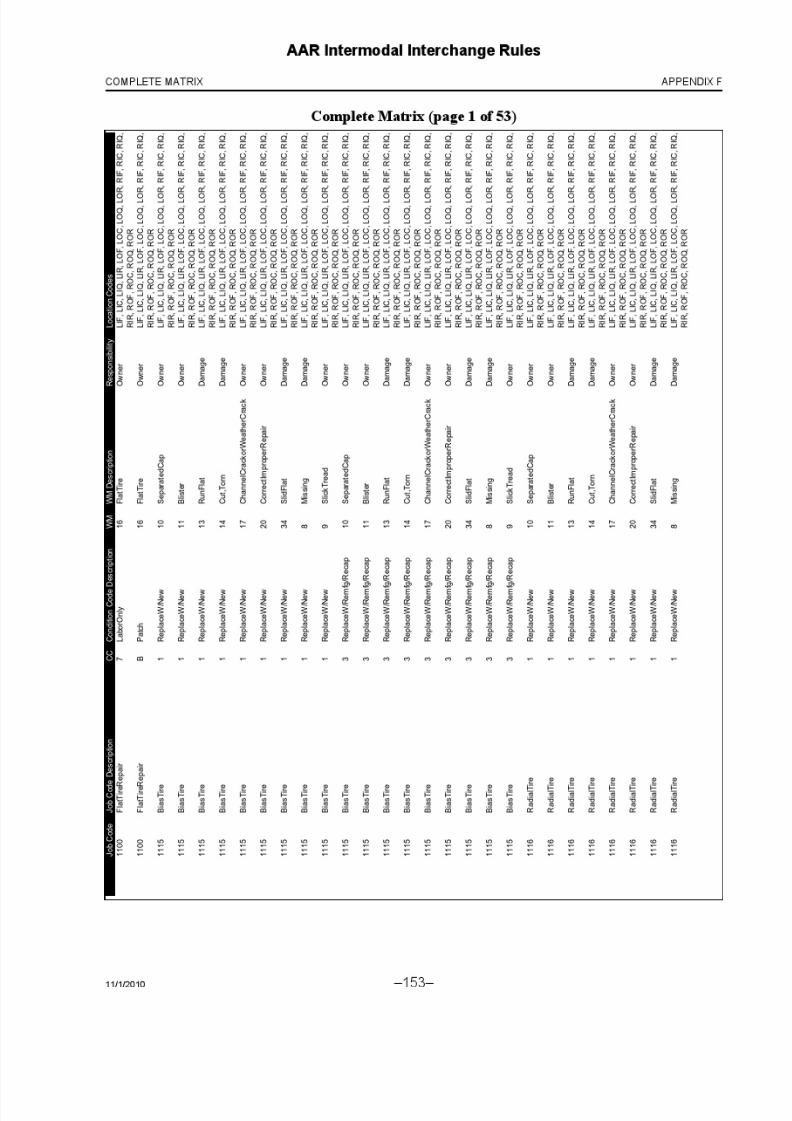
8/23/2019 AAR Intermodal Interchange Rules
http://slidepdf.com/reader/full/aar-intermodal-interchange-rules 171/224
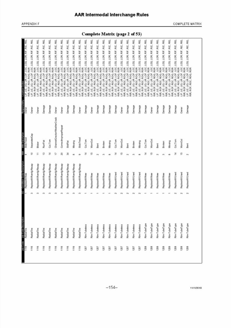
8/23/2019 AAR Intermodal Interchange Rules
http://slidepdf.com/reader/full/aar-intermodal-interchange-rules 172/224
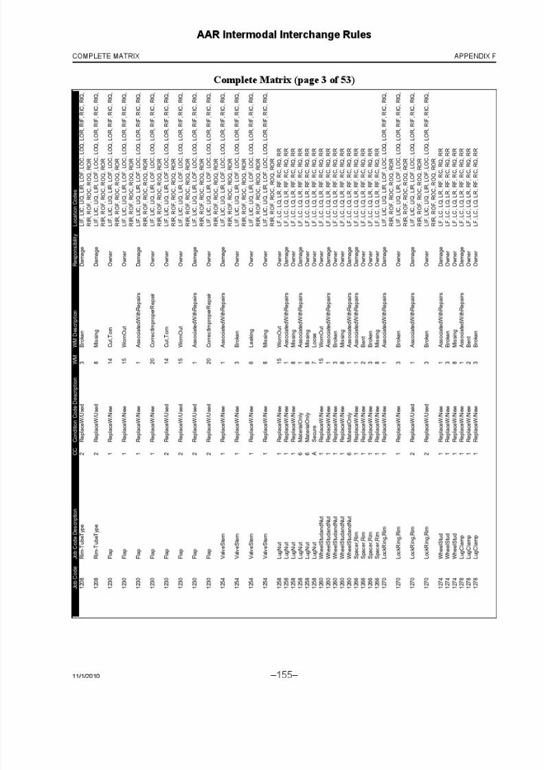
8/23/2019 AAR Intermodal Interchange Rules
http://slidepdf.com/reader/full/aar-intermodal-interchange-rules 173/224

8/23/2019 AAR Intermodal Interchange Rules
http://slidepdf.com/reader/full/aar-intermodal-interchange-rules 174/224

8/23/2019 AAR Intermodal Interchange Rules
http://slidepdf.com/reader/full/aar-intermodal-interchange-rules 175/224

8/23/2019 AAR Intermodal Interchange Rules
http://slidepdf.com/reader/full/aar-intermodal-interchange-rules 176/224

8/23/2019 AAR Intermodal Interchange Rules
http://slidepdf.com/reader/full/aar-intermodal-interchange-rules 177/224

8/23/2019 AAR Intermodal Interchange Rules
http://slidepdf.com/reader/full/aar-intermodal-interchange-rules 178/224

8/23/2019 AAR Intermodal Interchange Rules
http://slidepdf.com/reader/full/aar-intermodal-interchange-rules 179/224
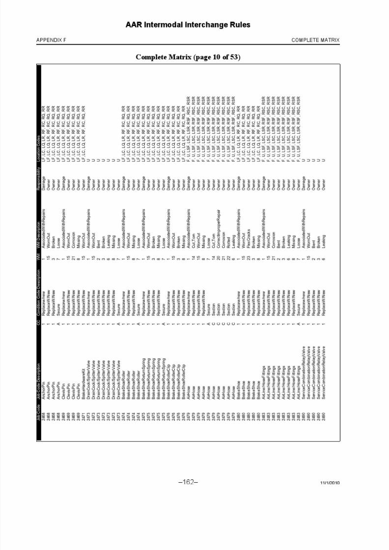
8/23/2019 AAR Intermodal Interchange Rules
http://slidepdf.com/reader/full/aar-intermodal-interchange-rules 180/224

8/23/2019 AAR Intermodal Interchange Rules
http://slidepdf.com/reader/full/aar-intermodal-interchange-rules 181/224
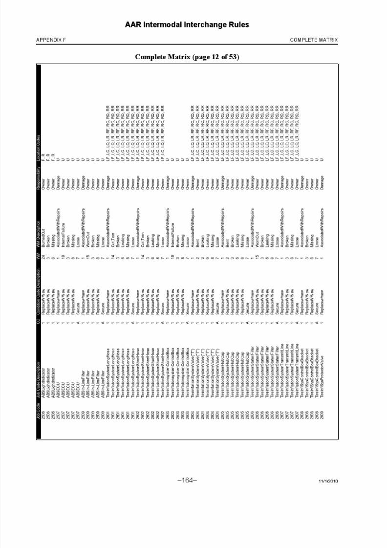
8/23/2019 AAR Intermodal Interchange Rules
http://slidepdf.com/reader/full/aar-intermodal-interchange-rules 182/224

8/23/2019 AAR Intermodal Interchange Rules
http://slidepdf.com/reader/full/aar-intermodal-interchange-rules 183/224
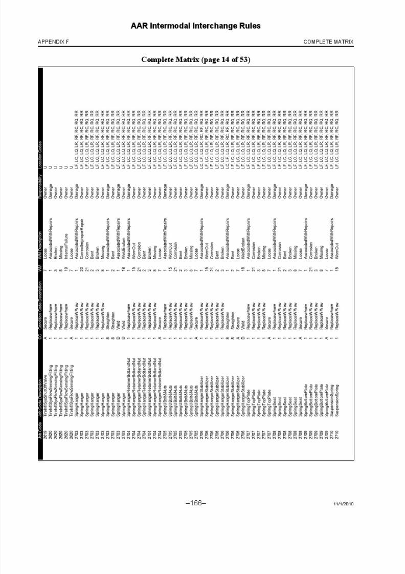
8/23/2019 AAR Intermodal Interchange Rules
http://slidepdf.com/reader/full/aar-intermodal-interchange-rules 184/224

8/23/2019 AAR Intermodal Interchange Rules
http://slidepdf.com/reader/full/aar-intermodal-interchange-rules 185/224

8/23/2019 AAR Intermodal Interchange Rules
http://slidepdf.com/reader/full/aar-intermodal-interchange-rules 186/224

8/23/2019 AAR Intermodal Interchange Rules
http://slidepdf.com/reader/full/aar-intermodal-interchange-rules 187/224
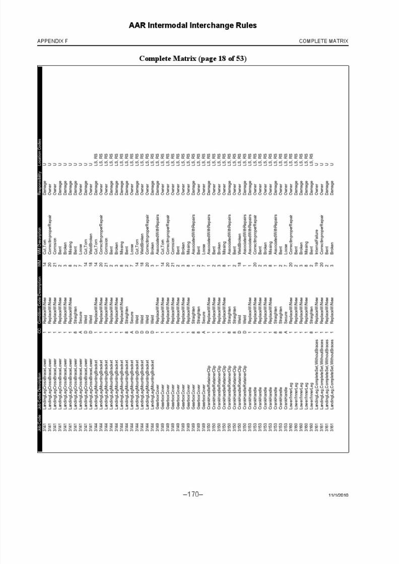
8/23/2019 AAR Intermodal Interchange Rules
http://slidepdf.com/reader/full/aar-intermodal-interchange-rules 188/224

8/23/2019 AAR Intermodal Interchange Rules
http://slidepdf.com/reader/full/aar-intermodal-interchange-rules 189/224

8/23/2019 AAR Intermodal Interchange Rules
http://slidepdf.com/reader/full/aar-intermodal-interchange-rules 190/224

8/23/2019 AAR Intermodal Interchange Rules
http://slidepdf.com/reader/full/aar-intermodal-interchange-rules 191/224

8/23/2019 AAR Intermodal Interchange Rules
http://slidepdf.com/reader/full/aar-intermodal-interchange-rules 192/224

8/23/2019 AAR Intermodal Interchange Rules
http://slidepdf.com/reader/full/aar-intermodal-interchange-rules 193/224
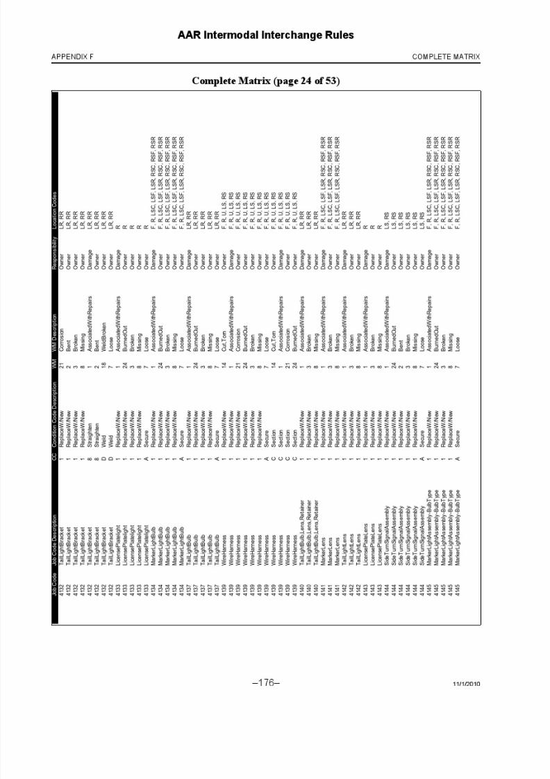
8/23/2019 AAR Intermodal Interchange Rules
http://slidepdf.com/reader/full/aar-intermodal-interchange-rules 194/224

8/23/2019 AAR Intermodal Interchange Rules
http://slidepdf.com/reader/full/aar-intermodal-interchange-rules 195/224

8/23/2019 AAR Intermodal Interchange Rules
http://slidepdf.com/reader/full/aar-intermodal-interchange-rules 196/224

8/23/2019 AAR Intermodal Interchange Rules
http://slidepdf.com/reader/full/aar-intermodal-interchange-rules 197/224

8/23/2019 AAR Intermodal Interchange Rules
http://slidepdf.com/reader/full/aar-intermodal-interchange-rules 198/224
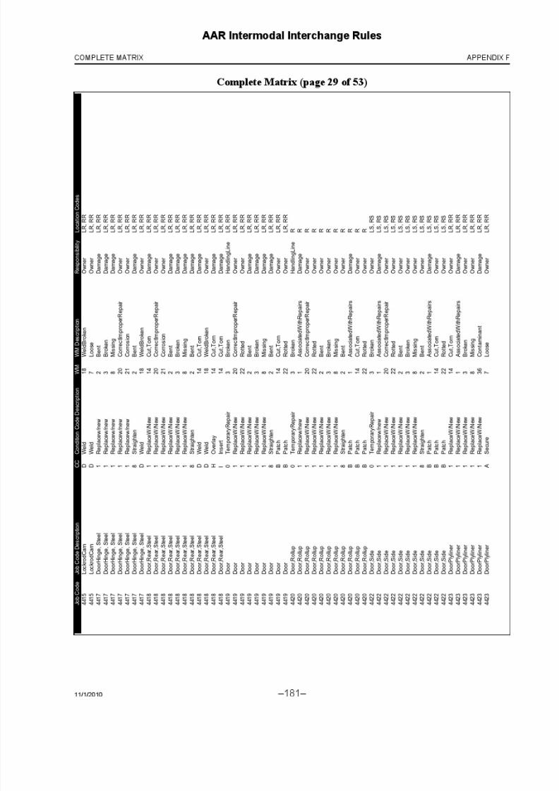
8/23/2019 AAR Intermodal Interchange Rules
http://slidepdf.com/reader/full/aar-intermodal-interchange-rules 199/224

8/23/2019 AAR Intermodal Interchange Rules
http://slidepdf.com/reader/full/aar-intermodal-interchange-rules 200/224

8/23/2019 AAR Intermodal Interchange Rules
http://slidepdf.com/reader/full/aar-intermodal-interchange-rules 201/224
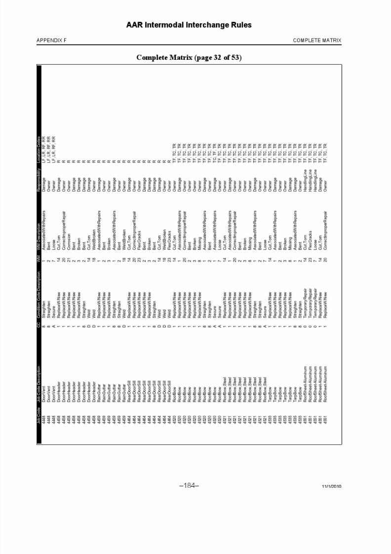
8/23/2019 AAR Intermodal Interchange Rules
http://slidepdf.com/reader/full/aar-intermodal-interchange-rules 202/224

8/23/2019 AAR Intermodal Interchange Rules
http://slidepdf.com/reader/full/aar-intermodal-interchange-rules 203/224

8/23/2019 AAR Intermodal Interchange Rules
http://slidepdf.com/reader/full/aar-intermodal-interchange-rules 204/224
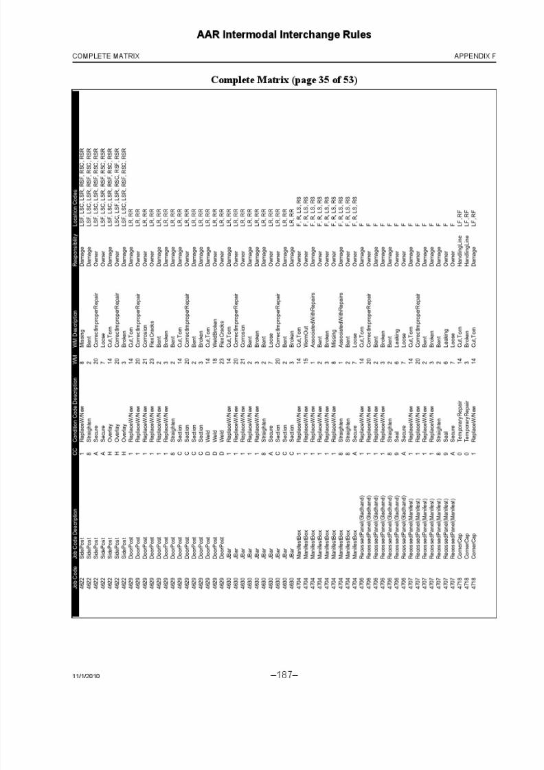
8/23/2019 AAR Intermodal Interchange Rules
http://slidepdf.com/reader/full/aar-intermodal-interchange-rules 205/224

8/23/2019 AAR Intermodal Interchange Rules
http://slidepdf.com/reader/full/aar-intermodal-interchange-rules 206/224
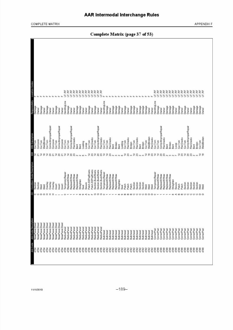
8/23/2019 AAR Intermodal Interchange Rules
http://slidepdf.com/reader/full/aar-intermodal-interchange-rules 207/224

8/23/2019 AAR Intermodal Interchange Rules
http://slidepdf.com/reader/full/aar-intermodal-interchange-rules 208/224

8/23/2019 AAR Intermodal Interchange Rules
http://slidepdf.com/reader/full/aar-intermodal-interchange-rules 209/224

8/23/2019 AAR Intermodal Interchange Rules
http://slidepdf.com/reader/full/aar-intermodal-interchange-rules 210/224

8/23/2019 AAR Intermodal Interchange Rules
http://slidepdf.com/reader/full/aar-intermodal-interchange-rules 211/224

8/23/2019 AAR Intermodal Interchange Rules
http://slidepdf.com/reader/full/aar-intermodal-interchange-rules 212/224

8/23/2019 AAR Intermodal Interchange Rules
http://slidepdf.com/reader/full/aar-intermodal-interchange-rules 213/224

8/23/2019 AAR Intermodal Interchange Rules
http://slidepdf.com/reader/full/aar-intermodal-interchange-rules 214/224
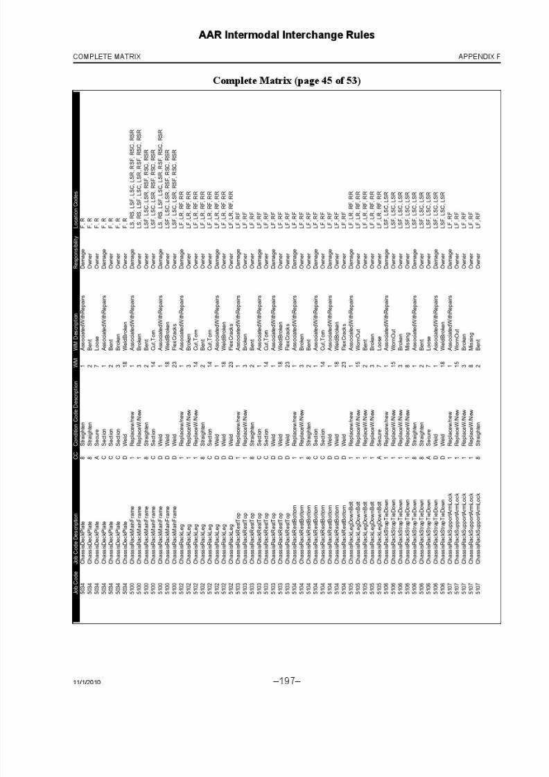
8/23/2019 AAR Intermodal Interchange Rules
http://slidepdf.com/reader/full/aar-intermodal-interchange-rules 215/224

8/23/2019 AAR Intermodal Interchange Rules
http://slidepdf.com/reader/full/aar-intermodal-interchange-rules 216/224

8/23/2019 AAR Intermodal Interchange Rules
http://slidepdf.com/reader/full/aar-intermodal-interchange-rules 217/224

8/23/2019 AAR Intermodal Interchange Rules
http://slidepdf.com/reader/full/aar-intermodal-interchange-rules 218/224

8/23/2019 AAR Intermodal Interchange Rules
http://slidepdf.com/reader/full/aar-intermodal-interchange-rules 219/224

8/23/2019 AAR Intermodal Interchange Rules
http://slidepdf.com/reader/full/aar-intermodal-interchange-rules 220/224

8/23/2019 AAR Intermodal Interchange Rules
http://slidepdf.com/reader/full/aar-intermodal-interchange-rules 221/224

8/23/2019 AAR Intermodal Interchange Rules
http://slidepdf.com/reader/full/aar-intermodal-interchange-rules 222/224

8/23/2019 AAR Intermodal Interchange Rules
http://slidepdf.com/reader/full/aar-intermodal-interchange-rules 223/224

8/23/2019 AAR Intermodal Interchange Rules
http://slidepdf.com/reader/full/aar-intermodal-interchange-rules 224/224
AAR Intermodal Interchange Rules
APPENDIX F COMPLETE MATRIX


![HANDLING HAZARDOUS … · IMPLEMENTED 04/2018 05/2016 I [RP-854] 1 AAR Manual of Standards and Recommended Practices Intermodal Equipment Manual RP-854 HANDLING HAZARDOUS MATERIALS](https://img.pdfslide.us/doc/110x75/5b8141fe7f8b9ae87c8be456/handling-hazardous-implemented-042018-052016-i-rp-854-1-aar-manual-of-standards.jpg)