Embed Size (px)
Citation preview

“Concrete Paving in NOVA”Conventional and Pervious
Concrete & Streets andLocal Roads
Rod Meyers, PE,BASF Construction Chemicals

How Thick Should ThePervious Concrete
Pavement Be?

ACI 552-10, Report on PerviousConcrete, section 3.3.1.1 Parking Lots
“The practicalrange of designthicknesses for
perviousconcrete
pavements isfrom 5 to 12 in
for plain parkinglots.”

VIRGINIA DCR STORMWATERDESIGN SPECIFICATION No. 7
PERMEABLE PAVEMENTVERSION 1.7March 1, 2011
Table 7.6Typical Thickness: 4 to
8 inches

Light DutyPortland Cement Concrete
Pavements

Calculating Stressesin Pavement

PCA Pavement Stress CalculationsDoes anyone have a i5 Processor
with Turbo Boost Technology?

ACPA Design Software
Terminalserviceability index
Allowable crackedslabs
Pavement designlife
Reliability
Traffic inputs

Light Duty Pavement Design
Long term durability attractive
Complex design methods are Overkill
Not represented by AASHO Road Test
AASHTO design method are overkill
Design and QC based on fc

Design Tools

Types of Concrete Pavement
• Plain jointed pavement
• Plain-doweled pavement
• Reinforced-doweled pavement
• Continuously reinforcedpavement

Typical ConcreteRoads and Streets
• Plain jointed pavement• Plain-doweled pavement• Reinforced-doweled pavement• Continuously reinforcedpavement

Curbs and Gutters
• Reduce edgestresses
• Used as sideforms
• Allowed to userounded joints

SupportTraffic Loads
Functional Requirement

Flexural Strength
• Pavements are subject tobending stresses
• Flexural stresses and flexuralstrength govern design

Flexural Strength (MOR)• ASTM C 78 Third-Point Loading of 6” by 6”
by 30” beams• High variability with flexural strength testing• Results sensitive to specimen preparation,
handling and curing procedures

Flexural Strength (MOR) fromCompressive Strength Data
ACI 330For smooth-textured and round-shaped aggregates
MOR = 8 * (f’c)1/2 (psi)
For rough-textured and angular-shaped aggregates
MOR = 10 * (f’c)1/2 (psi)
f’c = specified compressive strength (psi)

Flexural Strength fromCompressive Strength DataPCA Design and Control of
Concrete Mixtures
MOR = K * (f’c)1/2 (psi)
K = factor from 7.5 to 10.0
f’c = specified compressive strength (psi)

Calculated Flexural Strength, MOR (psi)
Compressive Strength, f’c (psi)
3,500 psi 4,000 psi 4500 psi
MOR = 7.5 * (f’c)1/2 440 470 500
MOR = 8.0 * (f’c)1/2 470 500 540
MOR = 8.5 * (f’c)1/2 500 530 570
MOR = 9.0 * (f’c)1/2 530 570 600
MOR = 9.5 * (f’c)1/2 560 600 640
MOR = 10.0 * (f’c)1/2 590 630 670

Flexural Strength based onCompressive Strength
• MR = 8.7 * fc1/2
• fc = 4,000 psi
• MR = 8.7 *(4,000)1/2 = 550 psi

Subgrade Support
• Concretedistributesload throughslab action
• Load spreadover largearea

Subgrade SupportMeasured as:
• Modulus of Subgrade Reaction (k)
• California Bearing Ratio (CBR)
• Bearing Value
• Resistance Value (R)
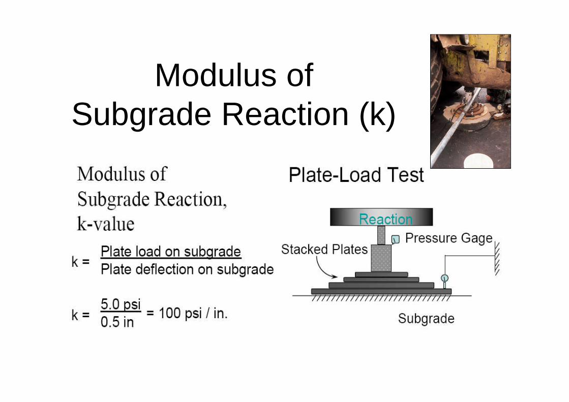
Modulus ofSubgrade Reaction (k)

Subbase Improves Structural Capacity

ImprovingSubgradeSupport
withGranularSubbase
PCA
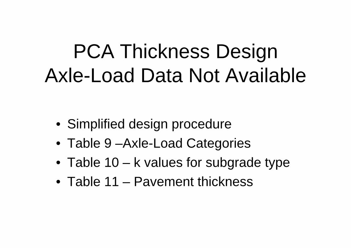
PCA Thickness DesignAxle-Load Data Not Available
• Simplified design procedure
• Table 9 –Axle-Load Categories
• Table 10 – k values for subgrade type
• Table 11 – Pavement thickness

Table 9 –Axle-Load Categories

Table 10 – k valuesfor subgrade type
k = 100 pci

ImprovingSubgradeSupport
withGranularSubbase
PCA

Table 10 – k valuesfor subgrade type
k = 150 pci

Table 11 Pavement Thickness

PCA Design of ConcretePavements for City Streets
• Method 1 / Table 1
• Method 2 Thickness Design
• Select k-value
• Chart 1– Pavement thickness
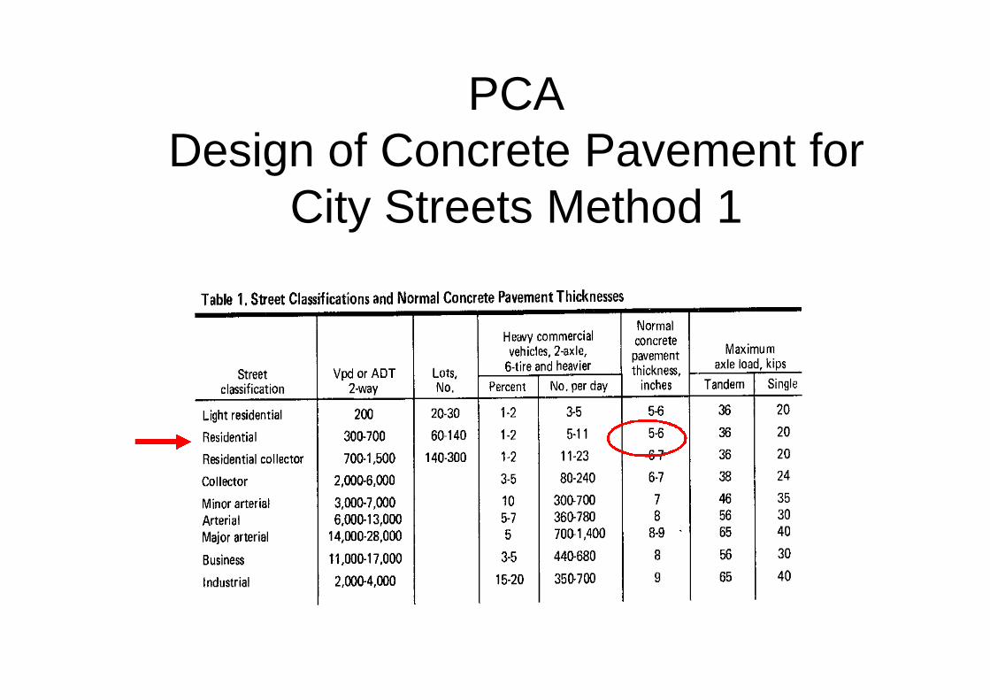
PCADesign of Concrete Pavement for
City Streets Method 1

PCADesign of Concrete Pavement for
City Streets Method 2


ACI 330R-08Thickness Design
• Table 3.3 Traffic categories
• Table 3.1 Subgrade support
• Table 3.4 Pavement thicknessrecommendation

ACI 330. Table 3.1Subgrade soil types and
approximate support values
k = 140 pci

Traffic categories

ACI 330. Table 3.1Subgrade soil types and
approximate support values
k = 140 pci
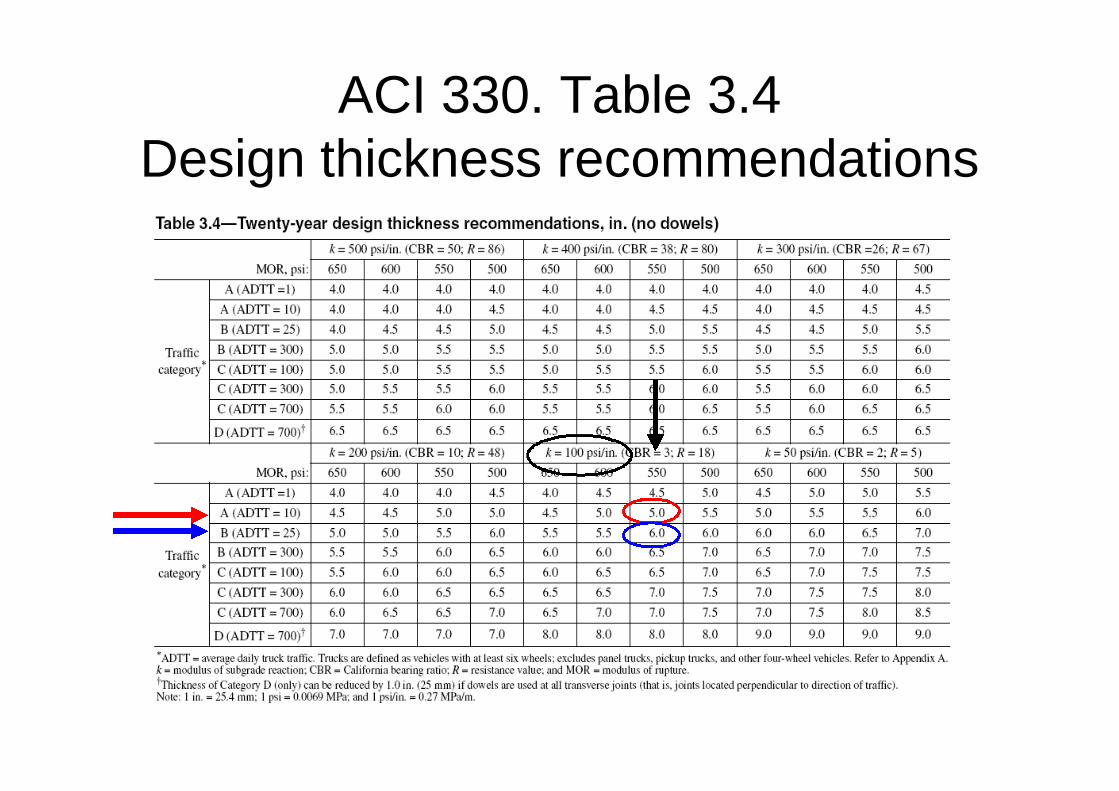
ACI 330. Table 3.4Design thickness recommendations

Thickness Design of PerviousConcrete

Pervious Concrete Applications
Parking lots
Streets/roadsshoulders
Sidewalks
Driveways
Light traffic areas


ASTM C1701 Infiltration Rate as a Function ofASTM C1688 Void Content

Specified Strength of PerviousConcrete
VIRGINIA DCR STORMWATERDESIGN SPECIFICATION No. 7
PERMEABLE PAVEMENTVERSION 1.7March 1, 2011
Table 7.6Compressive strength: 2.8 to 28 Mpa
(400 psi to 4,000 psi)

Calculated Flexural Strength, MOR (psi)
Compressive Strength, f’c (psi)
400 psi 2,000 psi 4,000 psi
MOR = 7.5 * (f’c)1/2 150 340 470
MOR = 8.0 * (f’c)1/2 160 360 510
MOR = 8.5 * (f’c)1/2 170 380 540
MOR = 9.0 * (f’c)1/2 180 400 570
MOR = 9.5 * (f’c)1/2 190 420 600
MOR = 10.0 * (f’c)1/2 200 450 630

The American Concrete Institute CommitteeReport ACI 522R-Pervious Concrete,
Chapter 7.2.2 states:“Guidance for structural design of conventional concrete
pavements is provided in ACI 330R for parking lots and inACI 325.12R for streets and roads. These documents cover
many different aspects of paving design. The structuraldesign recommendations in these documents, however,
are not necessarily applicable for use with perviouspavement. As there are no standardized test methods
for strength of pervious concrete, design andspecification by strength should be avoided”.

Flexural Strength vrs. Void Content
0
100
200
300
400
500
600
700
0 5 10 15 20 25 30 35
Void Content, percent by volume
28
-day
Fle
xura
lS
tren
gth
,p
si
Best Fit Line
Data
Flexural Strength, Fmr = 832.8 – 20.3 * (void content, %), psi

Specified Void Content ofPervious Concrete
VIRGINIA DCR STORMWATERDESIGN SPECIFICATION No. 7
PERMEABLE PAVEMENTVERSION 1.7March 1, 2011
Table 7.6Open Void Content: 15% to 25%

Flexural Strength vrs. Void Content
0
100
200
300
400
500
600
700
0 5 10 15 20 25 30 35
Void Content, percent by volume
28
-day
Fle
xura
lS
tren
gth
,p
si
Best Fit Line
Data
Flexural Strength, Fmr = 832.8 – 20.3 * (void content, %), psi

Testing Fresh DensityASTM C1688 Density and Void Content ofFreshly Mixed Pervious Concrete
0.25 ft3 measure(standard air pot)
Standard ProctorHammer

Obtain sample ASTM C172Fill in 2 liftsDrop hammer full 12”Drop 20 times/lift
ASTM C1688

ASTM C1688 Void Contents

Consistency andWater Content
(1) Tennis, P.D., Leming, M.L., Akers, D.J., Pervious Concrete Pavements,Portland Cement Association, PCA Serial No. 2828, 2004, page 8
Too little water
Proper Amount of Water
Too much water


High water contentwithout stable paste
IncreasesChances ofAggregate
Raving

AbrasionResistanceTurning lanesand high trafficvolumeapplications maynot be suitable
Snow plows mayravel aggregate
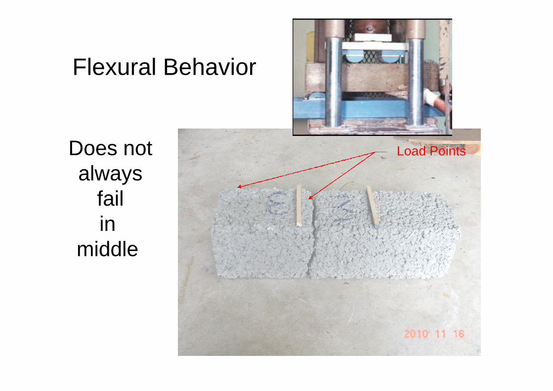
Flexural Behavior
Load PointsDoes notalways
failin
middle

What DesignStrength?
Engineering judgmentmay be the answer

Influence of Infiltration Rateof In-situ Soil

VIRGINIA DCR STORMWATERDESIGN SPECIFICATION No. 7
PERMEABLE PAVEMENTVERSION 1.7March 1, 2011
If the proposed permeable pavement area isdesigned to infiltrate runoff without underdrains,it must have a minimum infiltration rate of 0.5
inches per hour. Initially, projected soilinfiltration rates can be estimated from USDA-NRCS soil data, but they must be confirmed byan on-site infiltration measurement. Native soilsmust have silt/clay content less than 40% and
clay content less than 20%.

Group A : > 90% Sand<10% ClayPR > 5.67 in/hr
Group B : 10% -20% Clay50 to 90% SandPR 5.67 – 1.42 in/hr
Group C : 20% - 40% Clay< 50% SandPR 1.42 – 0.14 in/hr
Group D : > 40% Clay< 50% Sand
PR < 0.14 in/hr
Designers should note that if the underlying soils have a lowCalifornia Bearing Ratio (CBR) (less than 4%), they may need
to be compacted to at least 95% of the Standard ProctorDensity, which generally rules out their use for infiltration.

VIRGINIA DCR STORMWATERDESIGN SPECIFICATION No. 7
PERMEABLE PAVEMENTVERSION 1.7March 1, 2011
Designers should note that if the underlying soils have alow California Bearing Ratio (CBR) (less than 4%), they
may need to be compacted to at least 95% of the StandardProctor Density, which generally rules out their use for
infiltration.
CBR Range: 4 to 40Modulus of Subgrade Reaction: 125 to 400 pci


Support Provided by Bedding andReservoir Layer
y = 7.483x + 97.007
y = 12.789x + 160.88
0
100
200
300
400
500
600
700
800
900
0 10 20 30 40 50 60
Reservoir Thickness (inches)
Mo
du
lus
of
su
bg
rad
e
rea
cti
on
(ps
i/in
)k=100 psi/in
k=200 psi/in
Linear (k=100 psi/in)
Linear (k=200 psi/in)

ReservoirLayer


Structural Number System
Developed by from
American Association of State Highway Officials
Road Test Data in 1961
The Structural Number (SN) is
analytically given by:
SN = a1*D1 + a2*D2 + a3*D3 + a4*D4 …….where
ai = layer coefficient of layer i
Di = thickness of layer i

Structural Numbers
Pavement Component Structural Number
Portland Cement Concrete 0.50
Surface Course AsphaltConcrete Hot Mix
0.44
Base Course AsphaltConcrete Hot Mix
0.34
Stone Base 0.14

Specified Pavement Sections

7.0” Pervious PCC1.5” ACHM Surface
3.5” ACHM Base
8.0” Stone Base
Section6.0” PC Concrete22” Reservoir
Structural Numbers22” * 0.14 = 3.08
---------Total SN = 3.08
Section1.5” ACHM Surface3.5” ACHM Base8.0” Stone Base
Structural Numbers1.5” * 0.44 = 0.663.5” * 0.34 = 1.19
+ 8.0” * 0.14 = 1.12---------
Total SN = 2.97
Light Duty Parking Lot Pavement
22” Reservoir

7.0” Pervious PCC
26” Reservoir
2.0” ACHM Surface
4.5” ACHM Base
8.0” Stone Base
Section6.0” PC Concrete26.0” Reservoir
Structural Numbers26.0” * 0.14 = 3.64
---------Total SN = 3.64
Section2.0” ACHM Surface4.5” ACHM Base8.0” Stone Base
Structural Numbers2.0” * 0.44 = 0.884.5” * 0.34 = 1.53
+ 8.0” * 0.14 = 1.12---------
Total SN = 3.53
Heavy Duty Parking Lot Pavement

“It is just about thatsort of thing they would like”