Embed Size (px)
Citation preview

0.43
0.50" 100% Air*
TYPE: Glazed Wall Systems (Site-built)
Summary of Results
Condensation Resistance Factor - Frame (CRFf)
1/4" PPG Solarban 70XL (e=0.018*, #3)
Clear
AAMA 1503-09 THERMAL PERFORMANCE
TEST REPORT
Rendered to:
CR LAURENCE CO., INC.
Layer 1:
Gap:
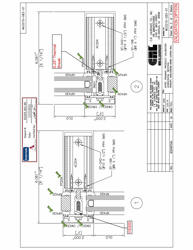
SERIES/MODEL: 2202/2202SG Curtain Wall
Thermal Transmittance (U-Factor)
1/4"
A1-D: Aluminum Spacer
78-3/4" x 78-3/4"Unit Size:
Condensation Resistance Factor - Glass (CRFg)
71
65
Layer 2:
Reference must be made to Report No. E6203.02-301-46, dated 07/25/15 for complete test
specimen description and data.
��������������� ���������������
��� ������������������ �������������
�������� � ���!��� ������" �� �#���!$% "&'"(

Report Number:
Test Date:
Report Date:
Test Sample Submitted by:
F
F
1.
2.
4. 0.0" +0.04" static pressure drop across specimen.
Test Results Summary:
Type:
Client
1. Average warm side ambient temperature
2. Average cold side ambient temperature
69.79
0.43
Condensation resistance factor - Glass (CRFg)
-0.41
Condensation resistance factor - Frame (CRFf) 71
CR LAURENCE CO., INC.
E6203.02-301-46
Vernon, California 90058
2100 East 38th Street
Test Sample Identification:
Series/Model:
07/09/15
2202/2202SG Curtain Wall
07/25/15
3. 15 mph dynamic wind applied to test specimen exterior.
AAMA 1503-09 THERMAL PERFORMANCE TEST REPORT
65
Thermal transmittance due to conduction (U)
(U-factors expressed in Btu/hr·ft2·F)
Test Procedure: The condensation resistance factor (CRF) and thermal transmittance (U) were
determined in accordance with AAMA 1503-09, Voluntary Test Method for Thermal
Transmittance and Condensation Resistance of Windows, Doors and Glazed Wall Sections
Rendered to:
Glazed Wall Systems (Site-built)
��������������� ���������������
��� ������������������ �������������
�������� � ���!��� ������" �� �#���!$% "&'"(

Test Sample Description:
*Stated per Client/Manufacturer
N/A Non-Applicable
PPG Solarban 70XL (e=0.018*, #3)Layer 2: 1/4"
100% Air*
N/A*
1/4"
A1-D: Aluminum Spacer0.50"
Layer 1: Clear
Glazing Information:
Gas Fill Method:
Gap:
Desiccant: Yes
E6203.02-301-46
Page 2 of 9
Size:
Material: AT (0.25"): Aluminum with Thermal Breaks - All Members
78-3/4" x 78-3/4"
Anodized
Daylight Opening:
Frame:
Exterior Color: Grey
Corner Joinery:
Exterior
Interior Finish:
36" x 74-1/2" (x2) Glazing Method:
Grey Anodized
Square Cut / Screws / Sealed
Exterior Finish:
Interior Color:
��������������� ���������������
��� ������������������ �������������
�������� � ���!��� ������" �� �#���!$% "&'"(

Test Sample Description: (Continued)
Weatherstripping:
Hardware:
Drainage:
No hardware.
LocationDescription
No weatherstripping.
Quantity
E6203.02-301-46
Page 3 of 9
LocationDescription Quantity
Quantity
SizeDrainage Method
No visible weeps.
Location
��������������� ���������������
��� ������������������ �������������
�������� � ���!��� ������" �� �#���!$% "&'"(
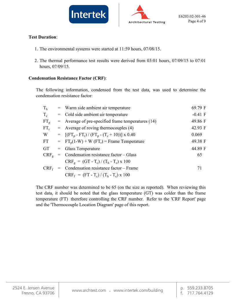
Test Duration:
1.
2.
Condensation Resistance Factor (CRF):
= F
= F
= F
= F
=
= F
= F
=
=
0.069
Tc
W
The following information, condensed from the test data, was used to determine the
condensation resistance factor:
69.79
Average of pre-specified frame temperatures (14) 49.86
42.93
Warm side ambient air temperatureTh
-0.41
FTr
FTp
The thermal performance test results were derived from 03:01 hours, 07/09/15 to 07:01
hours, 07/09/15.
The environmental systems were started at 11:59 hours, 07/08/15.
Cold side ambient air temperature
71
FT FTp(1-W) + W (FTr) = Frame Temperature 49.38
Glass Temperature 44.89
Condensation resistance factor – FrameCRFf
The CRF number was determined to be 65 (on the size as reported). When reviewing this
test data, it should be noted that the glass temperature (GT) was colder than the frame
temperature (FT) therefore controlling the CRF number. Refer to the 'CRF Report' page
and the 'Thermocouple Location Diagram' page of this report.
CRFf = (FT - Tc) / (Th - Tc) x 100
Average of roving thermocouples (4)
[(FTp - FTr) / (FTp - (Tc + 10))] x 0.40
65
GT
Condensation resistance factor – Glass CRFg
CRFg = (GT - Tc) / (Th - Tc) x 100
Page 4 of 9
E6203.02-301-46
��������������� ���������������
��� ������������������ �������������
�������� � ���!��� ������" �� �#���!$% "&'"(

Th = Average warm side ambient temperature F
Tc = Average cold side ambient temperature F
P = Static pressure difference across test specimen psf
15 mph dynamic perpendicular wind at exterior
Nominal sample area ft2
Total measured input to calorimeter Btu/hr
Calorimeter correction Btu/hr
Net specimen heat loss Btu/hr
U = Thermal Transmittance
Glazing Deflection:
0.43
Right Glazing
0.50"
Btu/hr·ft2·F
0.50"
1310.59
69.79
100.67
43.07
1411.26
-0.41
Thermal Transmittance (Uc):
Page 5 of 9
E6203.02-301-46
Left Glazing
0.00
0.48"
Required annual calibrations for the Architectural Testing, Inc., a subsidiary of Intertek
(Intertek-ATI), 'thermal test chamber' (ICN 004287) in Fresno, California were last conducted
in April 2015 in accordance with Intertek-ATI calibration procedure. A CTS Calibration
verification was performed March 2015. A Metering Box Wall Transducer and Surround Panel
Flanking Loss Characterization was performed June 2015.
0.55"0.53"
Center gap width at laboratory ambient
conditions on day of testing0.55"0.53"
Prior to testing the specimen was sealed with silicone on the interior side and checked for air
infiltration per Section 9.3.4.
The sample was inspected for the formation of frost or condensation, which may influence the
surface temperature measurements. The sample showed no evidence of condensation/frost at
the conclusion of the test.
Estimated center gap width upon receipt of
specimen in laboratory (after stabilization)
Center gap width at test conditions
Edge Gap Width
0.46"
��������������� ���������������
��� ������������������ �������������
�������� � ���!��� ������" �� �#���!$% "&'"(

Time: 05:00 05:30 06:00 06:30 07:01 AVERAGE
Pre-specified Thermocouples - Frame
43.3643.39 43.36
2
CRF Report
47.2847.25 47.28
E6203.02-301-46
Page 6 of 9
43.3543.34
47.25
52.64
47.26
43.48
52.63
54.96
56.55
52.21
21
23
5
7
8
54.95
52.23
43.44
54.98
52.66
43.51 43.52
52.64
51.76
14
52.23
50.15
49.2649.24
50.17
13
12
50.10
52.21
51.76
52.21
11
3
9
6
10
4
49.27
50.12
47.71
43.47
47.18
43.41
50.08
51.74
50.08
52.63
54.98
47.67
56.52
46.66
43.52
1 43.31
51.78
31.32
54.86
31.3315
18 40.30
56.5156.46
46.68
56.50
24
20
GT 44.90
22
41.64
43.48
49.41FT
69.80
Warm Side - Room Ambient Air Temperature
69.78
49.38
FTR
43.31
42.40
6565 65
71
-0.38
69.82
0.07
41.66 42.36
0.070.06
42.72 42.90
0.07 0.07
43.28
44.89
42.40
44.06
43.47
43.34
42.42 42.34
43.51
43.36 43.35
41.71 41.65
45.5945.5845.65
43.41
55.59
44.88
Cold Point (Roving) Thermocouples
41.73
46.66
54.96
50.03
51.67 51.74
52.20
54.93
52.14
50.08
47.61
50.09
49.16
46.60
47.68
49.26
50.16
40.29
49.86
Pre-specified Thermocouples - Glass
49.87
52.1552.10
31.29
17
16
45.62
40.29
31.28
54.8354.90
55.56
52.1652.15
49.81
45.58
40.26
19 55.57 55.52
44.90
49.88
40.30
FTP 49.88
40.30
54.82 54.8554.85
31.24
55.5455.60
41.71
-0.44
69.81
49.37 49.3849.38
-0.41
Cold Side - Room Ambient Air Temperature
69.74
-0.39
71
CRFg 65
71
-0.39
71
50.15
42.40
49.37
43.39
42.42
71
65 65
-0.46
42.73
71CRFf
43.04
69.79
0.07W
52.18
41.71
46.68 46.66
47.67
50.15
49.24
47.67
56.53
42.86
42.93
43.36
43.44
44.85
49.88
45.60
31.29
42.52
52.56
44.89
41.77
��������������� ���������������
��� ������������������ �������������
�������� � ���!��� ������" �� �#���!$% "&'"(

DRAG HERE,
Page 7 of 9
Thermocouple Location Diagram
SELECT DRAWING,
21.
E6203.02-301-46
Cold Point Locations
43.35
24.
43.47
23.
42.52
AND IDENTIFY COLD POINTS
22.
42.40
21
23
24
22
22
23
24
21
��������������� ���������������
��� ������������������ �������������
�������� � ���!��� ������" �� �#���!$% "&'"(

For INTERTEK-ATI
William Simon Smeds Kenny C. White
Technician Laboratory Manager
Individual-In-Responsible-Charge
WSS:ms
E6203.02-301-46
Attachments (pages): This report is complete only when all attachments listed are included.
Intertek-ATI will service this report for the entire test record retention period. Test records that
are retained such as detailed drawings, datasheets, representative samples of test specimens, or
other pertinent project documentation will be retained by Intertek-ATI for the entire test record
retention period. The test record retention end date for this report is July 09, 2019.
Intertek-ATI is accredited by the International Accreditation Service (IAS) under the specific test
methods listed under lab code TL-144, in accordance with the recognized International Standard
ISO/IEC 17025:2005. The laboratory’s accreditation or test report in no way constitutes or
implies product certification, approval, or endorsement by IAS.
Drawings (12)Appendix-A:
This report does not constitute certification of this product nor an opinion or endorsement by
this laboratory. It is the exclusive property of the client so named herein and relates only to the
specimen tested. This report may not be reproduced, except in full, without the written
approval of Intertek-ATI.
E6203.02-301-46
Page 8 of 9
��������������� ���������������
��� ������������������ �������������
�������� � ���!��� ������" �� �#���!$% "&'"(

This report produced from controlled document template ATI 00025(c), revised 03/14/2013.
Page 9 of 9
DateRev. #
0
Revision(s)Page(s)
Revision Log
All Original Report Issue. Work requested by Mr.
Gyu-Hyeon Kim of CR Laurence Co., Inc.
07/25/15
E6203.02-301-46

Appendix A: Drawings
E6203.02-301-46