Embed Size (px)
Citation preview
Aalto-1 Doc. No. A1-SYS-EID-01-v7
The Finnish Student Satellite Date: 16.10.2013Experiment Interface Document Page: 1 / 35
Aalto-1Experiment Interface Document
Aalto University
School of Electrical Engineering
Name Signature DatePrepared by Antti Kestilä, Antti
Näsilä, Maria Komu, Jaan Praks, Anssi Hakkarainen
Checked byApproved by
Aalto-1 Doc. No. A1-SYS-EID-01-v7
The Finnish Student Satellite Date: 16.10.2013Experiment Interface Document Page: 2 / 35
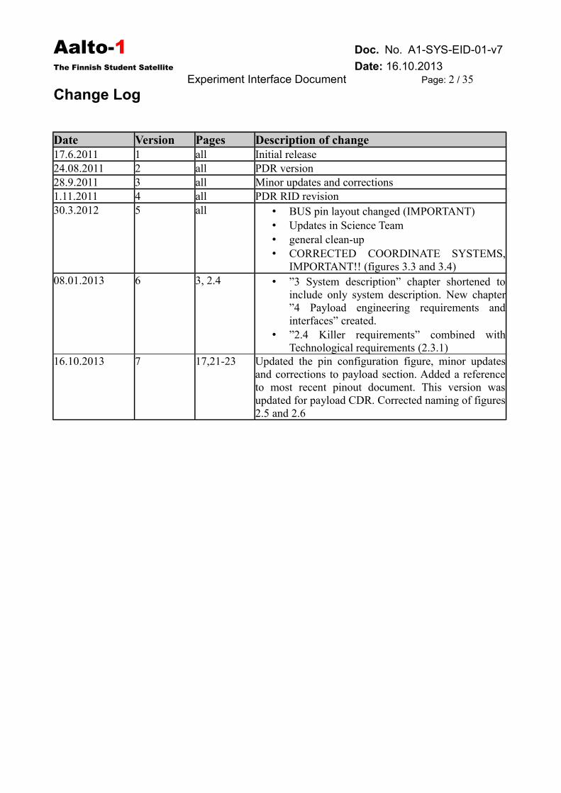
Change Log
Date Version Pages Description of change17.6.2011 1 all Initial release24.08.2011 2 all PDR version28.9.2011 3 all Minor updates and corrections1.11.2011 4 all PDR RID revision30.3.2012 5 all • BUS pin layout changed (IMPORTANT)
• Updates in Science Team• general clean-up• CORRECTED COORDINATE SYSTEMS,
IMPORTANT!! (figures 3.3 and 3.4)08.01.2013 6 3, 2.4 • ”3 System description” chapter shortened to
include only system description. New chapter”4 Payload engineering requirements andinterfaces” created.
• ”2.4 Killer requirements” combined withTechnological requirements (2.3.1)
16.10.2013 7 17,21-23 Updated the pin configuration figure, minor updatesand corrections to payload section. Added a referenceto most recent pinout document. This version wasupdated for payload CDR. Corrected naming of figures2.5 and 2.6
Aalto-1 Doc. No. A1-SYS-EID-01-v7
The Finnish Student Satellite Date: 16.10.2013Experiment Interface Document Page: 3 / 35
Contents
1 Introduction.......................................................................................................................................6
1.1 Scope..........................................................................................................................................6
1.2 Applicable Documents................................................................................................................6
1.3 Reference Documents.................................................................................................................6
1.4 Abbreviations and Acronyms.....................................................................................................6
2System Interfaces................................................................................................................................7
2.1 Mission and System Overview...................................................................................................7
2.2 Satellite Bus..............................................................................................................................16
2.2.1Overview............................................................................................................................16
2.2.2Bus protocol........................................................................................................................16
2.3 Module Specification................................................................................................................16
2.4Bus connector specification.......................................................................................................18
2.5 Communications.......................................................................................................................20
2.5.1 Data Rate...........................................................................................................................20
VHF/UHF...............................................................................................................................20
S-band.....................................................................................................................................21
3 Payload Engineering Requirements and Interfaces.........................................................................21
3.1 Aalto-1 Spectral Imager (AaSI)................................................................................................21
Overview................................................................................................................................21
Accommodation.....................................................................................................................21
Electrical Interface..................................................................................................................21
Mechanical Interface..............................................................................................................22
Thermal Interface...................................................................................................................22
Power......................................................................................................................................22
3.2 Compact Radiation Monitor (RADMON)................................................................................22
Overview................................................................................................................................22
Accommodation.....................................................................................................................23
Electrical Interface..................................................................................................................23
Command, telemetry and data interfaces...............................................................................23
Mechanical Interface..............................................................................................................23
Thermal Interface...................................................................................................................23
Power......................................................................................................................................23
3.3 Electrostatic Plasma Brake (EPB)............................................................................................23
Aalto-1 Doc. No. A1-SYS-EID-01-v7
The Finnish Student Satellite Date: 16.10.2013Experiment Interface Document Page: 4 / 35
Overview................................................................................................................................23
Accommodation.....................................................................................................................23
Electrical Interface..................................................................................................................23
Command, telemetry, and data interfaces...............................................................................24
Mechanical Interface..............................................................................................................24
Thermal Interface...................................................................................................................24
Power......................................................................................................................................24
4 Ground Segment..............................................................................................................................25
4.1 Ground Station..........................................................................................................................25
4.1.1 Configuration.....................................................................................................................25
4.1.2 Ground Support Equipment...............................................................................................25
5 Environmental Requirements and Conditions.................................................................................26
5.1 Thermal Environment...............................................................................................................26
5.2 Radiation Environment.............................................................................................................26
6 Verification Requirements...............................................................................................................26
6.1 Verification Concept.................................................................................................................26
6.2 Analysis....................................................................................................................................26
6.3 Instrument Level Testing..........................................................................................................26
6.3.1 Overview...........................................................................................................................26
6.3.2 Random Vibration Test Levels..........................................................................................27
6.3.3 Thermal-Vacuum Cycling..................................................................................................27
6.4 Calibration................................................................................................................................27
6.5 System Level Assembly, Integration and Testing.....................................................................28
7 Management Requirements.............................................................................................................29
7.1 Organization Management.......................................................................................................29
7.1.1 Organization......................................................................................................................29
7.1.2 Project Executives.............................................................................................................29
7.1.3 Steering Group...................................................................................................................29
7.1.4 Science Team.....................................................................................................................30
7.1.5 Instrument Responsibilities...............................................................................................30
7.1.6 System Responsibilities (Subject to change).....................................................................31
7.1.7 Student Teams....................................................................................................................31
7.2 Reviews....................................................................................................................................31
7.3 Documentation.........................................................................................................................31
8 Product Assurance Requirements....................................................................................................33
8.1 Management.............................................................................................................................33
8.2 Product Assurance Plan............................................................................................................33

Aalto-1 Doc. No. A1-SYS-EID-01-v7
The Finnish Student Satellite Date: 16.10.2013Experiment Interface Document Page: 5 / 35
8.3 Quality Assurance (QA)...........................................................................................................33
8.4 Materials and Components.......................................................................................................33
8.5 Cleanliness................................................................................................................................33
8.6 Non-conformance Reports and Waivers...................................................................................34
8.7Configuration Control...............................................................................................................35
8.8 Safety........................................................................................................................................35
8.9 Manufacturing Requirements...................................................................................................35
8.10 Integration and Testing Requirements....................................................................................35
Aalto-1 Doc. No. A1-SYS-EID-01-v7
The Finnish Student Satellite Date: 16.10.2013Experiment Interface Document Page: 6 / 35
1 Introduction
1.1 ScopeThis document's purpose is to give a comprehensive executive overview on the Aalto – 1 satelliteand its mission to any outside parties. It also works as an introduction to personnel joining theproject.
1.2 Applicable Documents
1.3 Reference Documents1. "CubeSat Design Specification", Rev. 12, 1.8.20092. "Cubesat Kit PCB Specification", Rev. A53. "PC/104 Specification", v. 2.5, Nov 20034. "Launch Services Program Level Poly Picosatellite Orbital Deployer (PPOD) and CubeSat
Requirements Document", NASA Launch Services Program, Rev. Basic, 24.7.20095. "General Environmental Verification Standard (GEVS)", GSFC-STD-7000, 4/20056. ECSS-Q-ST-30-02C - Failure modes, effects (and criticality) analysis (FMEA/FMECA),
6.3.20097. ECSS-Q-ST-30-11C - Derating - EEE components, 31.7.20088. ECSS-Q-ST-70-08C - Manual soldering of high-reliability electrical connections, 6.3.20099. A1-M-MA-01-v2 Document Format Description and Document Control, version 2,
20.12.201110. A1-THE-TN-02-V1 Thermal Interface Document11. AALTO – 1 NANOSATELLITE – TECHNICAL DESCRIPTION AND MISSION
OBJECTIVES, Geoscientific Instrumentation, Methods and Data Systems. 12. A1-SYS-IF-01-v6 Satellite Bus Pinout13. A1-OBH-DS-03-v6 OBC Communication Protocol
1.4 Abbreviations and AcronymsAalto-1 The student satellite developed in this project. The name covers both, the
project and the satellite.Aalto ELEC Aalto University School of Electrical EngineeringABCL As-Built Configuration Data ListADACS / ADCS Attitude determination and control systemADS Antenna Deployment SystemAIT Assembly, Integration and TestBCR Battery Charge RegulatorCIDL Configuration Item Data ListCOTS Commercial-off-the-shelfCSK CubeSat kitCubeSat a common nanosatellite standard
Aalto-1 Doc. No. A1-SYS-EID-01-v7
The Finnish Student Satellite Date: 16.10.2013Experiment Interface Document Page: 7 / 35
ECSS European Cooperation for Space Standardization EID Experiment Interface DocumentEM Engineering ModelEPB Electrostatic Plasma BrakeEPS Electrical Power SystemFMECA/FMEA Failure modes, effects (and criticality) analysisGSFC Goddard Space Flight CenterHISPICO Highly Integrated S-Band transmitter for Pico- and NanosatellitesICD Interface control documentITAR International Traffic in Arms Regulations LEO Low - Earth orbitLV Launch VehicleMIL Military grade componentMPPT Maximum Power Point TrackerNCR Nonconformance ReportNRB Nonconformance Review BoardOBC On-Board ComputerP-POD Poly-PicoSatellite Orbital DeployerPAP Product Assurance PlanPCB Printed Circuit BoardPCM Power Conditioning ModulePDM Power Distribution ModulePDR Preliminary Design ReviewPC/104 Stackable embedded computer bus standardPFM Proto-Flight ModelRBF Remove Before FlightRD# Reference Document #S/C SpacecraftS-Band Radio frequencies between 2 and 4 GHzSBC Single board computerSPEC SpectrometerT&C Telemetry and CommandTBC To Be ConfirmedTBD To Be DefinedTVT Thermal-Vacuum TestTXRUV ISIS VHF/UHF transceiver for small satellitesUHF Ultra High Frequency, 300 MHz - 3 GHzVHF Very High Frequency, 30 MHz - 300 MHz
2 System Interfaces
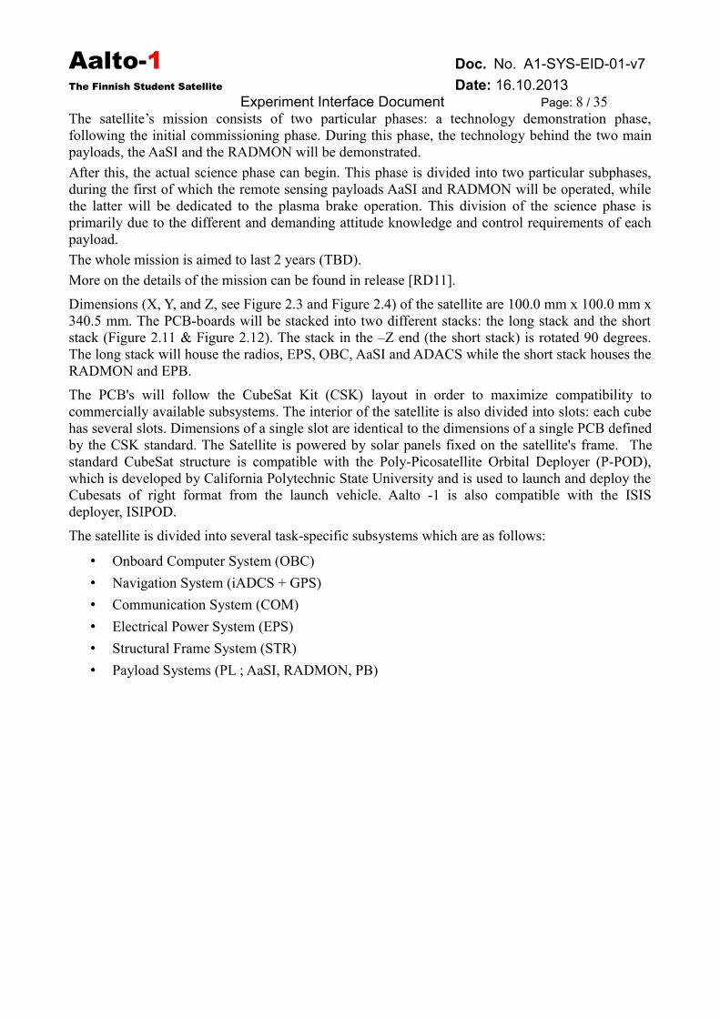
2.1 Mission and System OverviewAalto-1 is a three-unit (3U) CubeSat [RD1] with 3-axis stabilization.
It carries three very different payloads, all having specific attitude and communicationrequirements. The general interface diagram of the system is shown in Figure 2.1.
Aalto-1 Doc. No. A1-SYS-EID-01-v7
The Finnish Student Satellite Date: 16.10.2013Experiment Interface Document Page: 8 / 35
The satellite’s mission consists of two particular phases: a technology demonstration phase,following the initial commissioning phase. During this phase, the technology behind the two mainpayloads, the AaSI and the RADMON will be demonstrated.
After this, the actual science phase can begin. This phase is divided into two particular subphases,during the first of which the remote sensing payloads AaSI and RADMON will be operated, whilethe latter will be dedicated to the plasma brake operation. This division of the science phase isprimarily due to the different and demanding attitude knowledge and control requirements of eachpayload.
The whole mission is aimed to last 2 years (TBD).
More on the details of the mission can be found in release [RD11].
Dimensions (X, Y, and Z, see Figure 2.3 and Figure 2.4) of the satellite are 100.0 mm x 100.0 mm x340.5 mm. The PCB-boards will be stacked into two different stacks: the long stack and the shortstack (Figure 2.11 & Figure 2.12). The stack in the –Z end (the short stack) is rotated 90 degrees.The long stack will house the radios, EPS, OBC, AaSI and ADACS while the short stack houses theRADMON and EPB.
The PCB's will follow the CubeSat Kit (CSK) layout in order to maximize compatibility tocommercially available subsystems. The interior of the satellite is also divided into slots: each cubehas several slots. Dimensions of a single slot are identical to the dimensions of a single PCB definedby the CSK standard. The Satellite is powered by solar panels fixed on the satellite's frame. Thestandard CubeSat structure is compatible with the Poly-Picosatellite Orbital Deployer (P-POD),which is developed by California Polytechnic State University and is used to launch and deploy theCubesats of right format from the launch vehicle. Aalto -1 is also compatible with the ISISdeployer, ISIPOD.
The satellite is divided into several task-specific subsystems which are as follows:
• Onboard Computer System (OBC)
• Navigation System (iADCS + GPS)
• Communication System (COM)
• Electrical Power System (EPS)
• Structural Frame System (STR)
• Payload Systems (PL ; AaSI, RADMON, PB)
Aalto-1 Doc. No. A1-SYS-EID-01-v7
The Finnish Student Satellite Date: 16.10.2013Experiment Interface Document Page: 9 / 35
Figure 2.1: Aalto – 1 general interface diagram.

Aalto-1 Doc. No. A1-SYS-EID-01-v7
The Finnish Student Satellite Date: 16.10.2013Experiment Interface Document Page: 10 / 35
Figure 2.3: Outer frame of the satellite
Figure 2.4: Stack model of the Aalto-1 satellite
Aalto-1 Doc. No. A1-SYS-EID-01-v7
The Finnish Student Satellite Date: 16.10.2013Experiment Interface Document Page: 11 / 35
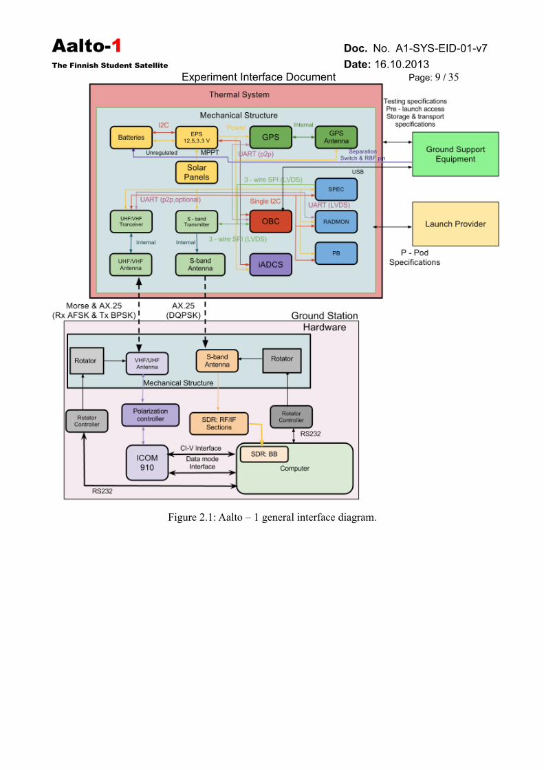
Figure 2.5: Long stack support plate
Aalto-1 Doc. No. A1-SYS-EID-01-v7
The Finnish Student Satellite Date: 16.10.2013Experiment Interface Document Page: 12 / 35
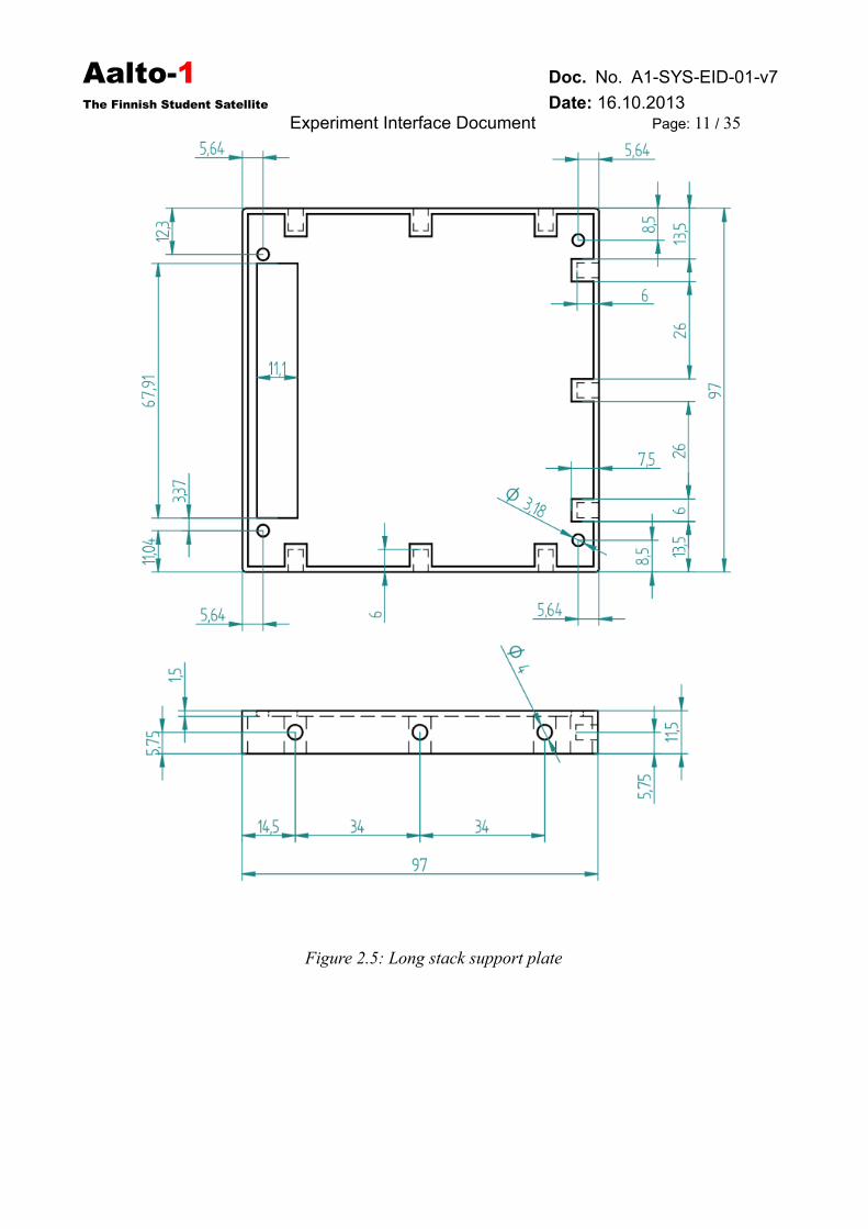
Figure 2.6: Short stack support plate
Aalto-1 Doc. No. A1-SYS-EID-01-v7
The Finnish Student Satellite Date: 16.10.2013Experiment Interface Document Page: 13 / 35
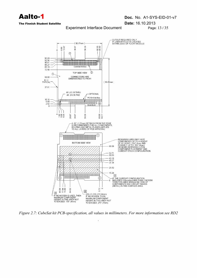
Figure 2.7: CubeSat kit PCB-specification, all values in millimeters. For more information see RD2
.
Aalto-1 Doc. No. A1-SYS-EID-01-v7
The Finnish Student Satellite Date: 16.10.2013Experiment Interface Document Page: 14 / 35
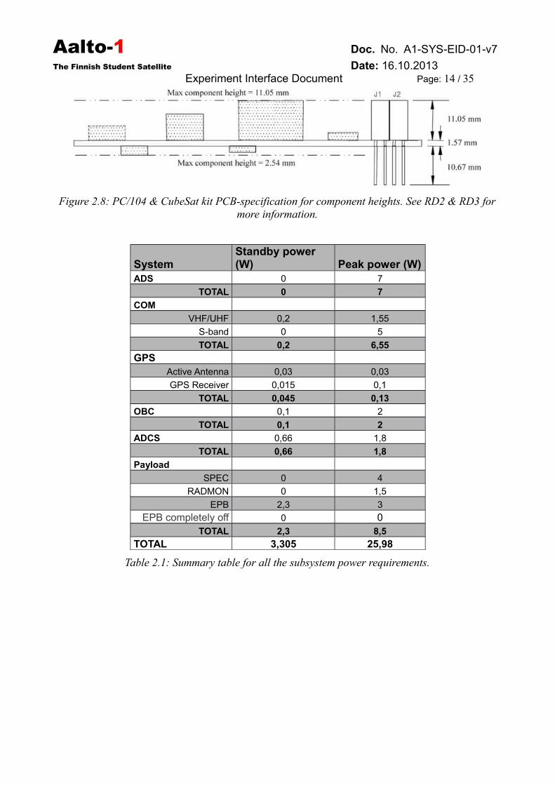
Figure 2.8: PC/104 & CubeSat kit PCB-specification for component heights. See RD2 & RD3 formore information.
SystemStandby power (W) Peak power (W)
ADS 0 7
TOTAL 0 7
COM
VHF/UHF 0,2 1,55
S-band 0 5
TOTAL 0,2 6,55
GPS
Active Antenna 0,03 0,03
GPS Receiver 0,015 0,1
TOTAL 0,045 0,13
OBC 0,1 2
TOTAL 0,1 2
ADCS 0,66 1,8
TOTAL 0,66 1,8
Payload
SPEC 0 4
RADMON 0 1,5
EPB 2,3 3
EPB completely off 0 0TOTAL 2,3 8,5
TOTAL 3,305 25,98
Table 2.1: Summary table for all the subsystem power requirements.
Aalto-1 Doc. No. A1-SYS-EID-01-v7
The Finnish Student Satellite Date: 16.10.2013Experiment Interface Document Page: 15 / 35
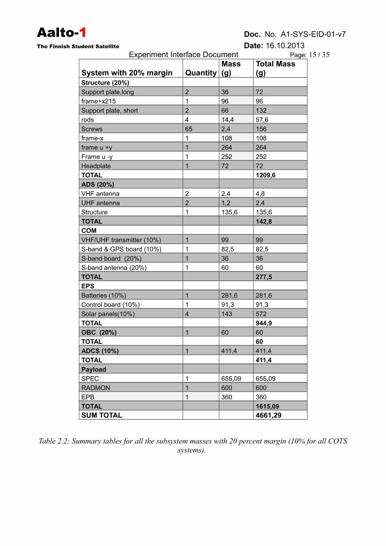
System with 20% margin QuantityMass (g)
Total Mass (g)
Structure (20%)
Support plate,long 2 36 72
frame+x215 1 96 96
Support plate, short 2 66 132
rods 4 14,4 57,6
Screws 65 2,4 156
frame-x 1 108 108
frame u +y 1 264 264
Frame u -y 1 252 252
Headplate 1 72 72
TOTAL 1209,6
ADS (20%)
VHF antenna 2 2,4 4,8
UHF antenna 2 1,2 2,4
Structure 1 135,6 135,6
TOTAL 142,8
COM
VHF/UHF transmitter (10%) 1 99 99
S-band & GPS board (10%) 1 82,5 82,5
S-band board (20%) 1 36 36
S-band antenna (20%) 1 60 60
TOTAL 277,5
EPS
Batteries (10%) 1 281,6 281,6
Control board (10%) 1 91,3 91,3
Solar panels(10%) 4 143 572
TOTAL 944,9
OBC (20%) 1 60 60
TOTAL 60
ADCS (10%) 1 411,4 411,4
TOTAL 411,4
Payload
SPEC 1 655,09 655,09
RADMON 1 600 600
EPB 1 360 360
TOTAL 1615,09
SUM TOTAL 4661,29
Table 2.2: Summary tables for all the subsystem masses with 20 percent margin (10% for all COTSsystems).
Aalto-1 Doc. No. A1-SYS-EID-01-v7
The Finnish Student Satellite Date: 16.10.2013Experiment Interface Document Page: 16 / 35
2.2 Satellite Bus
2.2.1 Overview
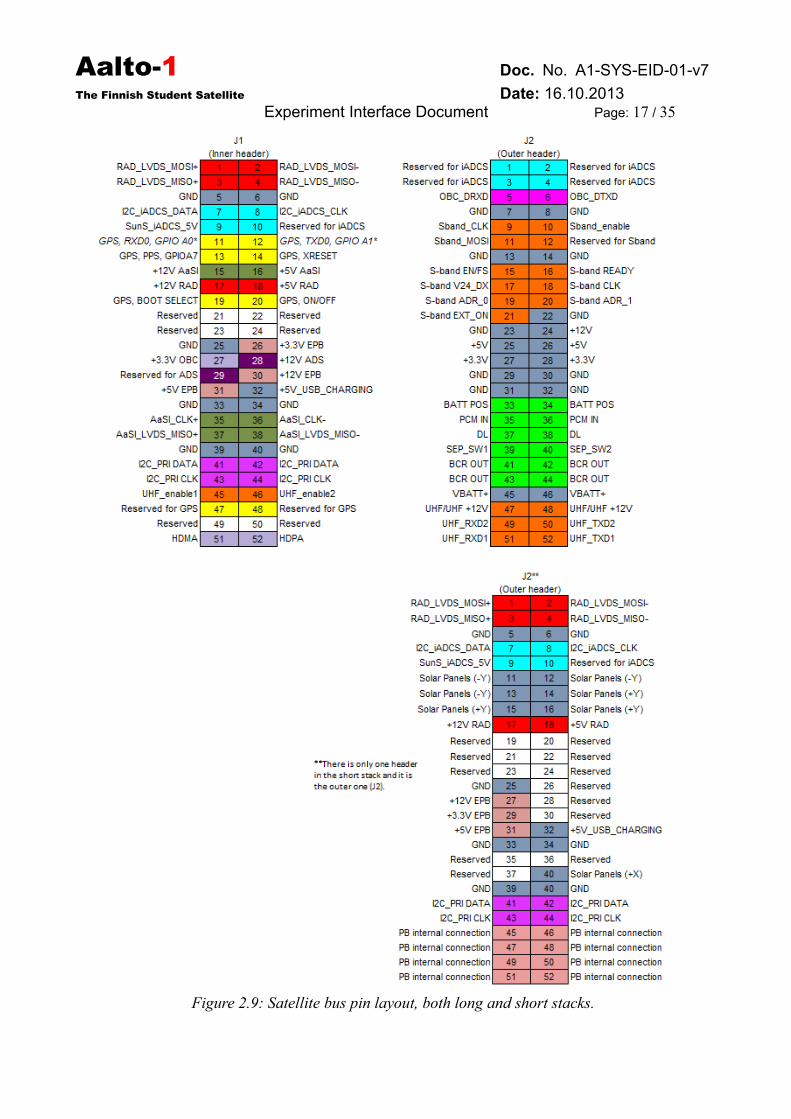
Aalto-1 uses a CubeSatKit-standard connector and a PCB-layout. The standard is derived from thePC/104-standard. The connector is a stack-through connector divided in to two headers and formsthe backbone of the Aalto-1 bus. In the long stack the satellite bus is located on the +y side of thesatellite (see Figure 2.4 and Figure 2.11). In the short stack the satellite bus is located in the +z sideof the stack (Figure 2.12). The inner header is removed from the short stack PCB's. The short stackwill be connected to the long stack by TBD. All pins are not necessarily connected to the short stackheaders. The pin layout for Aalto-1 satellite is shown in Figure 2.9. The main data bus between theOBC and satellite subsystems will be I2C, with UART and 3 – wire SPI, see Figure 2.1.
The detailed description of the stack pin configurations can be found in Aalto-1 InterfaceSheet and in document [RD12].
2.2.2 Bus protocol
See document [RD13] for more details.
2.3 Module SpecificationAll single slot modules must follow the CSK PCB standard (Figure 2.7) unless stated otherwise.The standard slot height is 15.16 mm (Figure 2.8), but different connectors can be used if necessary,as long as they are compatible with the standard connector. If a module is larger than one slot, thenthe outer dimensions must follow the CSK PCB specifications. The outer parts of the module mustalso be compatible with the stack support plate specifications (Figure 2.5 and 2.6). The PCBs aredivided into the long stack and the short stack, which can be seen in Figures 2.11 and 2.12. Thedimensions for each module can also been seen from these figures. The stack support plates aredifferent in the long stack and the short stack, so it must be kept in mind in which stack the moduleis located. The satellite bus must always go through the module uninterrupted.
Aalto-1 Doc. No. A1-SYS-EID-01-v7
The Finnish Student Satellite Date: 16.10.2013Experiment Interface Document Page: 17 / 35
Figure 2.9: Satellite bus pin layout, both long and short stacks.
Aalto-1 Doc. No. A1-SYS-EID-01-v7
The Finnish Student Satellite Date: 16.10.2013Experiment Interface Document Page: 18 / 35
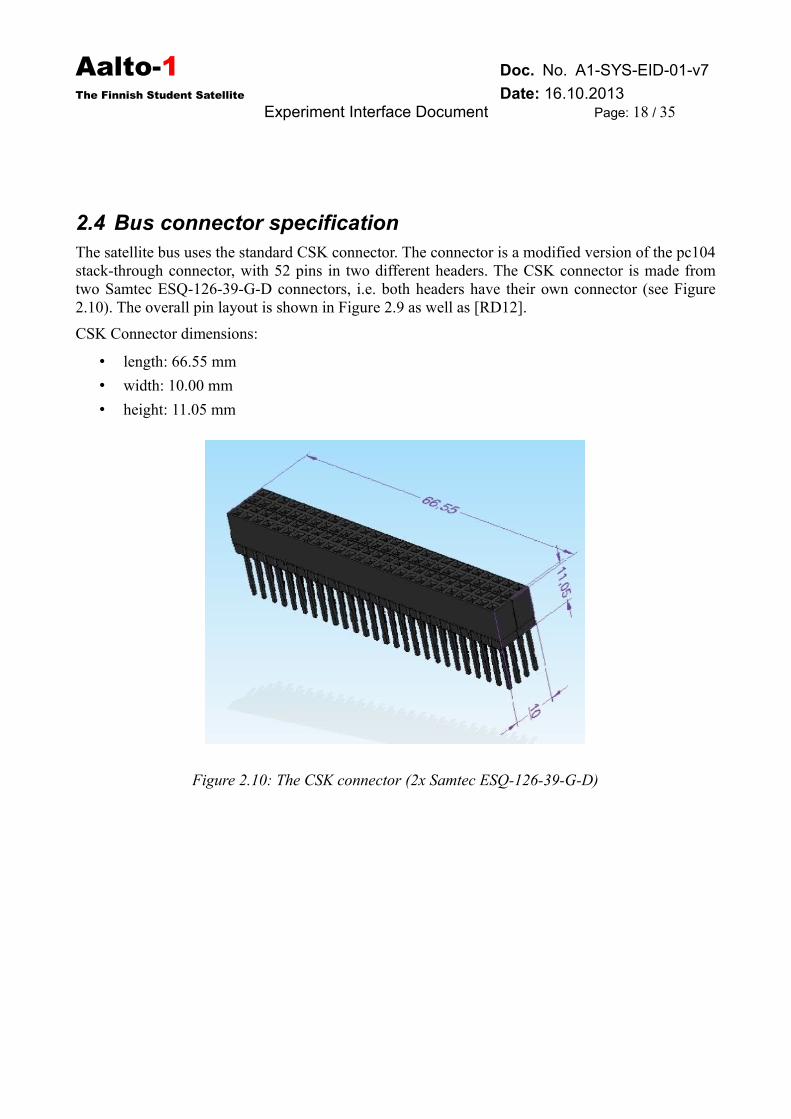
2.4 Bus connector specificationThe satellite bus uses the standard CSK connector. The connector is a modified version of the pc104stack-through connector, with 52 pins in two different headers. The CSK connector is made fromtwo Samtec ESQ-126-39-G-D connectors, i.e. both headers have their own connector (see Figure2.10). The overall pin layout is shown in Figure 2.9 as well as [RD12].
CSK Connector dimensions:
• length: 66.55 mm
• width: 10.00 mm
• height: 11.05 mm
Figure 2.10: The CSK connector (2x Samtec ESQ-126-39-G-D)
Aalto-1 Doc. No. A1-SYS-EID-01-v7
The Finnish Student Satellite Date: 16.10.2013Experiment Interface Document Page: 19 / 35
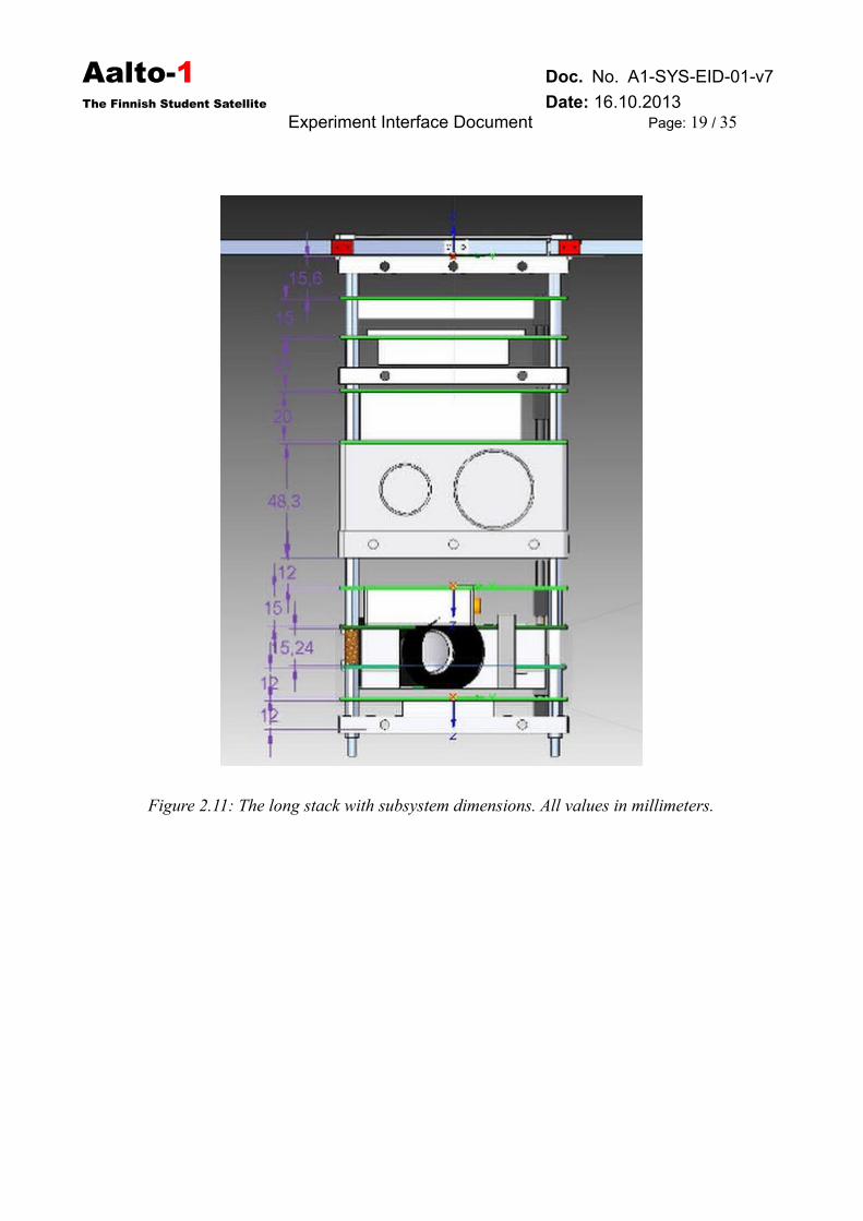
Figure 2.11: The long stack with subsystem dimensions. All values in millimeters.
Aalto-1 Doc. No. A1-SYS-EID-01-v7
The Finnish Student Satellite Date: 16.10.2013Experiment Interface Document Page: 20 / 35
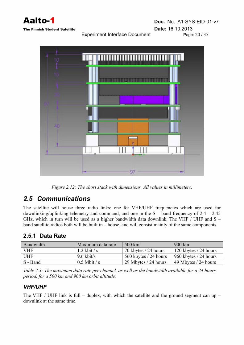
Figure 2.12: The short stack with dimensions. All values in millimeters.
2.5 CommunicationsThe satellite will house three radio links: one for VHF/UHF frequencies which are used fordownlinking/uplinking telemetry and command, and one in the S – band frequency of 2.4 – 2.45GHz, which in turn will be used as a higher bandwidth data downlink. The VHF / UHF and S –band satellite radios both will be built in – house, and will consist mainly of the same components.
2.5.1 Data Rate
Bandwidth Maximum data rate 500 km 900 kmVHF 1.2 kbit / s 70 kbytes / 24 hours 120 kbytes / 24 hoursUHF 9.6 kbit/s 560 kbytes / 24 hours 960 kbytes / 24 hoursS - Band 0.5 Mbit / s 29 Mbytes / 24 hours 49 Mbytes / 24 hours
Table 2.3: The maximum data rate per channel, as well as the bandwidth available for a 24 hours period, for a 500 km and 900 km orbit altitude.
VHF/UHF
The VHF / UHF link is full – duplex, with which the satellite and the ground segment can up –downlink at the same time.
Aalto-1 Doc. No. A1-SYS-EID-01-v7
The Finnish Student Satellite Date: 16.10.2013Experiment Interface Document Page: 21 / 35
S-band
With the S-band downlink the maximum data rate is ca. 500 kbaud/s, with a Minimum Shift Keying(MSK) modulation scheme, with an output power of 30 dBm.
3 Payload Engineering Requirements and Interfaces
3.1 Aalto-1 Spectral Imager (AaSI)
Overview
The Spectral Imager on board Aalto-1 will act as the main payload of the satellite. It will beconnected to the satellite by the satellite bus.
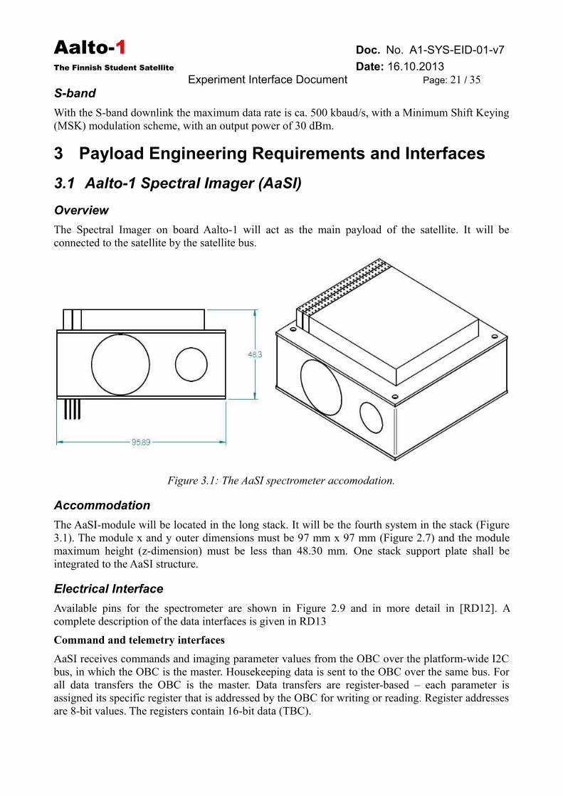
Figure 3.1: The AaSI spectrometer accomodation.
Accommodation
The AaSI-module will be located in the long stack. It will be the fourth system in the stack (Figure3.1). The module x and y outer dimensions must be 97 mm x 97 mm (Figure 2.7) and the modulemaximum height (z-dimension) must be less than 48.30 mm. One stack support plate shall beintegrated to the AaSI structure.
Electrical Interface
Available pins for the spectrometer are shown in Figure 2.9 and in more detail in [RD12]. Acomplete description of the data interfaces is given in RD13
Command and telemetry interfaces
AaSI receives commands and imaging parameter values from the OBC over the platform-wide I2Cbus, in which the OBC is the master. Housekeeping data is sent to the OBC over the same bus. Forall data transfers the OBC is the master. Data transfers are register-based – each parameter isassigned its specific register that is addressed by the OBC for writing or reading. Register addressesare 8-bit values. The registers contain 16-bit data (TBC).
Aalto-1 Doc. No. A1-SYS-EID-01-v7
The Finnish Student Satellite Date: 16.10.2013Experiment Interface Document Page: 22 / 35
Data interface
The image data is transferred from the AaSI buffer memory to the OBC via an SPI-over-LVDSinterface. The OBC is the master, thus generating the clock and select signals. The data transfer issimplex, no data is sent from the OBC to the AaSI over this I/F.
The bit rate is 45 Mbit/s, determined by the clock frequency of the OBC microcontroller. Data istransferred as 16 bits per pixel. A full buffer memory, 16Mpix, can be transferred to the OBC in 5.7seconds (minimum).
Mechanical Interface
The long stack support plate shall be a part of the spectrometer module mechanical frame. Thepreliminary mass is 656 grams, based on discussion with VTT.
Thermal Interface
The acceptable temperature range shall be from -30 to +40 °C (TBC).
Power
Power demands according to VTT are 12 V, 4.0 W (5 V, 3.0 W) during image acquisition, and aminimum of 0 W in idle/standby conditions.
3.2 Compact Radiation Monitor (RADMON)
Overview
The RADMON will act as a secondary payload, and it will be connected by the satellite bus. Themodule will be built by Universities of Helsinki and Turku.
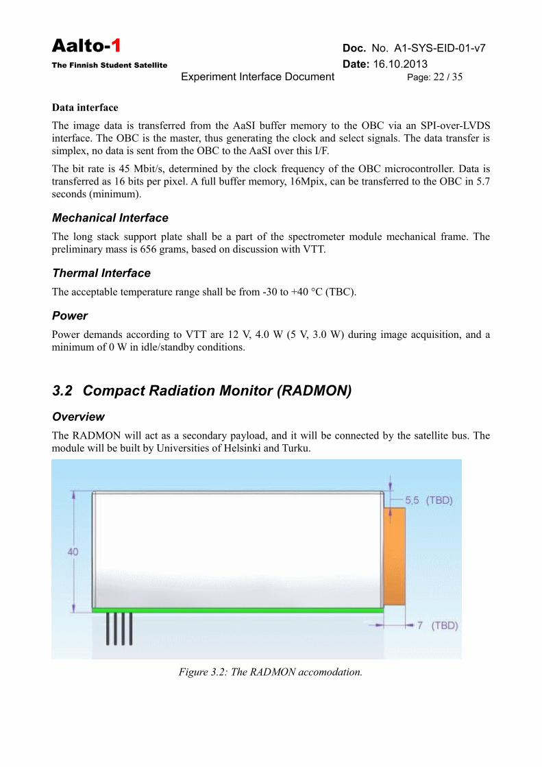
Figure 3.2: The RADMON accomodation.
Aalto-1 Doc. No. A1-SYS-EID-01-v7
The Finnish Student Satellite Date: 16.10.2013Experiment Interface Document Page: 23 / 35
Accommodation
The RADMON is located in the short stack (last system in the stack), so the PCB-stack is rotated 90degrees in relation to the long PCB-stack. The RADMON module (Figure 3.2) y and z dimensionsmust be 90.17 mm x 95.89 mm and the maximum module height (x-dimension) must be less than40 mm. The outermost PCB's must also be compatible with the short stack support platespecification (Figure 2.6) and the CSK standard. The detector unit must not protrude more than 7mm (TBC) from the PCB to the -z direction and the gap between the detector and the support platemust be more than 0 mm (i.e. it cannot go inside the support plate).
Electrical Interface
Available pins for RADMON are shown in Figure 2.9 and in more detail in [RD12]. The RADMONwill have dedicated +5V and +12V power lines.
Command, telemetry and data interfaces
RADMON shall transfer two – ways telemetry, commands as well as payload data through adedicated UART–over–LVDS line. The platform–wide I2C line will be used as a backup, in whichthe OBC is the master. See more details in [RD13].
Mechanical Interface
The RADMON module shall be fixed to the stack support plates by TBD and the RADMONdetector shall be fixed to the satellite frame by the short stack support plate.
Thermal Interface
The acceptable temperature range shall be from -30 to +40 °C (TBC).
Power
The RADMON shall use as peak power 1.5 W. The RADMON module must shut down completelywhen either of the voltage lines is shut down.
3.3 Electrostatic Plasma Brake (EPB)
Overview
The Electrostatic Plasma Brake will act as a de-orbiting device, and it will be connected by thesatellite bus.
Accommodation
The EPB is located in the short stack, meaning the stack is rotated 90 degrees in relation to the mainPCB-stack. The Plasma Brake module y and z dimensions must be 90.17 mm x 95.89 mm and thex-dimension must be under 45 mm. The outermost PCB's must also be compatible with the shortstack support plate specification [TBC] (Figure 2.5) and the CSK standard.
Electrical Interface
Available pins for the EPB are shown in Figure 2.9 and in more detail in [RD12]
Aalto-1 Doc. No. A1-SYS-EID-01-v7
The Finnish Student Satellite Date: 16.10.2013Experiment Interface Document Page: 24 / 35
Command, telemetry, and data interfaces
The EPB shall transfer two–ways telemetry, commands as well as payload data through theplatform-wide I2C line, in which the OBC is the master. See more details in [RD13].
Mechanical Interface
The EPB shall be fixed with screws within the remainder of the stack, as seen in Figure 2.12. Themotor of the EPB is fixed with screws to its designated PCB.
Thermal Interface
The acceptable temperature range shall be from -30 to +40 °C (TBC).
Power
The Electrostatic Plasma Brake shall use as peak power 3 W, with an ON-state power usage of 2.3W when not being deployed.
Aalto-1 Doc. No. A1-SYS-EID-01-v7
The Finnish Student Satellite Date: 16.10.2013Experiment Interface Document Page: 25 / 35
4 Ground Segment
4.1 Ground StationThe primary ground station for the Aalto-1 mission will be located in Otaniemi, Finland. It ismainly operated by the Department of Radio Science and Engineering of the Aalto UniversitySchool of Electrical Engineering (Aalto ELEC). The ground station will also be part of the GENSOnetwork.
Currently the UHF/VHF ground-station is operational, and has been used to both send and receivesignals to LEO radio amateur satellites. The satellite tracking is performed using Gpredict, an open-source real-time satellite tracking software.
4.1.1 Configuration
The ground station has antennas for UHF/VHF frequency bands, and will be capable of receiving and transmitting in both bands using a software defined radio FunCube Pro, and will have one for receiving and transmitting in S – band through a software defined radio [TBD].
4.1.2 Ground Support Equipment
The Ground Support equipment includes tools for satellite diagnostics, servicing and transportation.
Aalto-1 Doc. No. A1-SYS-EID-01-v7
The Finnish Student Satellite Date: 16.10.2013Experiment Interface Document Page: 26 / 35
5 Environmental Requirements and Conditions
5.1 Thermal EnvironmentThe thermal environment for the satellite is described in more detail in the thermal interfacedocument (RD10, A1-THE-TN-02-V1 Thermal Interface Document). The preliminary simulations(A1-THE-TN-03-V1) show that the temperatures inside the satellite shall be between -40°C and+80°C. (TBC)
5.2 Radiation EnvironmentTBD
6 Verification Requirements
6.1 Verification ConceptThe verification objectives of the instruments are to qualify the design, to ensure that the instrumentis acceptable for use in its spacecraft environment and to confirm instrument performance duringthe mission.
Verification can be accomplished by Analysis, Tests and Inspection.
6.2 AnalysisAnalyses to be performed before manufacturing the Protoflight models are:
• FMECA according to ECSS-Q-ST-30-02C
• Electrical components derating and worst case analysis according to ECSS-Q-ST-30-11
• Structural stress analysis
Thermal analysis is not required on instrument level (thermal requirements will be verified byTVT). Thermal analysis will be done on satellite level.
6.3 Instrument Level Testing
6.3.1 Overview
Requirements derived in this document based on GSFC-STD-7000 may be superseded bylaunch provider requirements as soon as the launch vehicle (LV) is identified.
Testing shall be performed to meet all launch provider requirements. According to CubeSat DesignSpecifications document if launch vehicle environment is unknown, GSFC-STD-7000(http://standards.gsfc.nasa.gov/gsfc-std/gsfc-std-7000.pdf) shall be used to derive testingrequirements. All flight hardware shall undergo protoflight and acceptance testing.
At least the following tests shall be applied to the instruments on unit level:
• Random Vibration
• Shock test
• Thermal Vacuum Test
• Visual Inspection
Aalto-1 Doc. No. A1-SYS-EID-01-v7
The Finnish Student Satellite Date: 16.10.2013Experiment Interface Document Page: 27 / 35
This is the minimum amount of tests and may be superseded by launch provider requirements.Other tests can be added as seen necessary by the instrument teams.
6.3.2 Random Vibration Test Levels
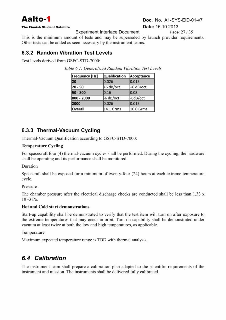
Test levels derived from GSFC-STD-7000:
Table 6.1: Generalized Random Vibration Test Levels
Frequency [Hz] Qualification Acceptance20 0.026 0.01320 - 50 +6 dB/oct +6 dB/oct50 - 800 0.16 0.08800 - 2000 -6 dB/oct -6dB/oct2000 0.026 0.013Overall 14.1 Grms 10.0 Grms
6.3.3 Thermal-Vacuum Cycling
Thermal-Vacuum Qualification according to GSFC-STD-7000:
Temperature Cycling
For spacecraft four (4) thermal-vacuum cycles shall be performed. During the cycling, the hardwareshall be operating and its performance shall be monitored.
Duration
Spacecraft shall be exposed for a minimum of twenty-four (24) hours at each extreme temperaturecycle.
Pressure
The chamber pressure after the electrical discharge checks are conducted shall be less than 1.33 x10 -3 Pa.
Hot and Cold start demonstrations
Start-up capability shall be demonstrated to verify that the test item will turn on after exposure tothe extreme temperatures that may occur in orbit. Turn-on capability shall be demonstrated undervacuum at least twice at both the low and high temperatures, as applicable.
Temperature
Maximum expected temperature range is TBD with thermal analysis.
6.4 CalibrationThe instrument team shall prepare a calibration plan adapted to the scientific requirements of theinstrument and mission. The instruments shall be delivered fully calibrated.
Aalto-1 Doc. No. A1-SYS-EID-01-v7
The Finnish Student Satellite Date: 16.10.2013Experiment Interface Document Page: 28 / 35
6.5 System Level Assembly, Integration and TestingThe instruments teams shall provide following models: Electrical Model (EL), Mechanical mock-up(no functionality) and Protoflight Model (PFM). EL and mechanical mock-up can be combined toone model.m Test requirements derived from CubeSat requirements are not very clear or exact, butgenerally they require vibration testing (random and sometimes sine), thermal cycling and bakeoutin vacuum, and possibly shock. Test requirements will become more exact when launch vehicle isidentified.
Satellite level test requirements according to CubeSat Design Specifications:
Random Vibration - Random vibration testing shall be performed as defined by LV provider, or ifunknown, GSFC-STD-7000.
Thermal Vacuum Bakeout - Thermal vacuum bakeout shall be performed to ensure properoutgassing of components. The test cycle and duration will be outlined by LV provider, or ifunknown, GSFC-STD-7000.
Visual Inspection - Visual inspection of the CubeSat and measurement of critical areas shall beperformed per the 3U CAC (3U CubeSat Acceptance Checklist) as appropriate.
Qualification - CubeSats may be required to survive qualification testing as outlined by the LVprovider. If LV environments are unknown, GSFC-STD-7000 (NASA GEVS). Qualification testingwill be performed at developer facilities. Additional testing may be required if modifications orchanges are made to the CubeSats after qualification testing.
Protoflight - All CubeSats shall survive protoflight testing as outlined by the LV provider. If LVenvironments are unknown, GSFC-STD-7000. Protoflight testing will be performed at developerfacilities. CubeSats SHALL NOT be disassembled or modified after protoflight testing.Disassembly of hardware after protoflight testing shall require the developer to submit a DAR andadhere to the waiver process prior to disassembly. Additional testing shall be required ifmodifications or changes are made to the CubeSats after protoflight testing.
Acceptance - After delivery and integration of the CubeSats into the P-POD, additional testing shallbe performed with the integrated system. The P-POD Integrator shall coordinate and performacceptance testing. After acceptance testing, developers may perform diagnostics through thedesignated P-POD diagnostic ports, and visual inspection of the system shall be performed by the P-POD Integrator. The P-POD SHALL NOT be de-integrated at this point. If a CubeSat failure isdiscovered, a decision to deintegrate the P-POD will be made by the developers, in that P-POD, andthe P-POD Integrator based on safety concerns. The developer is responsible for any additionaltesting required due to corrective modifications to deintegrated P-PODs and CubeSats.
Below is one example of CubeSat and launch pod Qualification and Acceptance Test Flow. Diagramis from the "Program Level Poly Picosatellite Orbital Deployer (PPOD) and CubeSat RequirementsDocument" provided by CubeSat Program.
Aalto-1 Doc. No. A1-SYS-EID-01-v7
The Finnish Student Satellite Date: 16.10.2013Experiment Interface Document Page: 29 / 35
7 Management Requirements
7.1 Organization ManagementThe organization at the top level is managed according to requirements of financing institutions.
7.1.1 Organization
Aalto-1 project is a cooperation project where several Finnish universities, institutes and companiesworking towards the common goal, the first Finnish satellite. Cooperation can be regulated withadditional agreements but the general framework is based on Memorandum of Understanding ororal agreements. Every participating party finances its own activities if not otherwise agreed.
The project is coordinated and managed by the Department of Radio Science and Engineering ofthe Aalto ELEC. The work is coordinated by professor of space technology Martti Hallikainen(responsible leader) and university teacher Jaan Praks (project coordinator).
The project will be guided by a steering group and advised by science team. The technical reviewswill be carried out by expert review panel (nominated for each project phase separately). Studentwork is organized according to teaching and project work needs. Organization on student team levelis kept as light as possible, student work in teams or individually on each topic.
Each instrument team shall nominate an Instrument manager to act as the project manager ofinstrument development. The Instrument manager shall act as a formal interface point for theinstrument side.
7.1.2 Project Executives
Project Lead: Prof. Martti Hallikainen,
e-mail: [email protected]
Visiting address: C228b, Otakaari 5 A, Espoo
Project Coordinator: Jaan Praks,
e-mail: [email protected],
skype: jaan.praks
gsm: +358505747975
Visiting address: C220, Otakaari 5 A, Espoo
7.1.3 Steering Group
Steering group is nominated by Aalto University. The Steering Group is responsible for generallines and financial side of the project. Steering group has meetings several times per year.
Steering group members:
• Tuija Pulkkinen, Chairman, Aalto University - School of Electrical Engineering
• Antti Räisänen, Aalto University - School of Electrical Engineering
• Keijo Heljanko, Aalto University - School of Science
• Martin Vermeer, Aalto University - School of Engineering
Aalto-1 Doc. No. A1-SYS-EID-01-v7
The Finnish Student Satellite Date: 16.10.2013Experiment Interface Document Page: 30 / 35
• Sami Franssila, Aalto University - School of Chemical Technology
• Yrjö Neuvo, MIDE Program
7.1.4 Science Team
The Science Team brings together teachers, experts from all over the consortium.The Science team is the main cooperation body of the project. Science Team is responsible forscience and technology of the satellite. Experts and Science Team members are invited to the teamupon request.
Associated Science Team Members currently are:
• Keijo Nikoskinen, Aalto University - School of Electrical Engineering
• Tomi Ylikorpi, Aalto University - School of Electrical Engineering
• Keijo Heljanko, Aalto University - School of Science
• Vesa Hirvisalo, Aalto University - School of Science
• Clemens Icheln, Aalto University - School of Electrical Engineering
• Heikki Saari, VTT
• Jarkko Antila, VTT
• Kai Viherkanto, VTT
• Pekka Janhunen, FMI
• Jouni Envall, FMI
• Petri Toivanen, FMI
• Maria Genzer, FMI
• Minna Palmroth, FMI
• Harri Haukka, FMI
• Hannu Koskinen, University of Helsinki
• Rami Vainio, University of Helsinki
• Juhani Peltonen, University of Turku
• Mikko Syrjäsuo, Aalto
• Pauli Stigell, TEKES• Matti Anttila, SSF• Ilkka Reis, RSI Oy• Jussi Liikkanen, Turun ammatikorkeakoulu• Merja Tornikoski, Aalto
7.1.5 Instrument Responsibilities
Spectrometer: Kai Viherkanto (VTT), [email protected]
Radiation monitor: Rami Vainio (University of Helsinki), [email protected]
Electrostatic Plasma Brake: Pekka Janhunen (FMI), [email protected]
Aalto-1 Doc. No. A1-SYS-EID-01-v7
The Finnish Student Satellite Date: 16.10.2013Experiment Interface Document Page: 31 / 35
7.1.6 System Responsibilities (Subject to change)
Project Manager: Jaan Praks, [email protected], +358505747975
Quality Manager: Maria Komu, [email protected]
System Engineers: Antti Kestilä, [email protected], Antti Näsilä, [email protected]
7.1.7 Student Teams
Student teams are the organization level where the most work is done. Student Teams aredynamically formed according to the need of teaching and the project. Project participants and theirshare of the work is documented in course reports. Student teams are instructed and guided byteachers and experts who coordinate their activities in Science Team meetings.
Student team list with contact information is maintained in project central document repository(Google drive).
7.2 ReviewsAt least the following reviews shall be held for instrument PFMs and in system level (combined orseparately):
● Critical Design Review (CDR) - The main objective of the CDR is to confirm the maturityand freeze the design for PFM manufacture.
● Test Readiness Review (TRR) - Gives a formal go-ahead for protoflight or acceptance testcampaign. It is checked that the product conforms to its design and is ready to be tested, andthe test facilities conform to the specifications, and the test procedures are approved.
● Post Test Review (PTR) - After testing Test Review Boards examine and evaluate unit andequipment level test results prior to formal acceptance of the hardware. The purpose of theDelivery Review is to check the product conforms to its specifications and is ready to bedelivered, and that the relevant documentation is completed and available.
After satellite integration:
● Flight Acceptance Review (FAR) - Is held after system integration, satellite integration tolaunch pod and acceptance testing. After this review satellite is accepted for launch.
Additional reviews can be arranged when needed.
7.3 DocumentationAll documentation shall be written in English and submitted as PDF files. Latest versions of alldocuments shall be available in the Aalto-1 Google Docs and Aalto-1 Dropbox. There shall be adocument control system containing document name, reference number and release date of thedocuments. Each subsystem and payload is responsible for their documentation and shall deliver alist of documents to PA manager when requested.
Document naming system should be for example following (described in more detail in [RD9]:
Document identifier is defined as:
<Project name>- <Instrument/Subsystem>- <Document type>-<Number> -<Version>
Aalto-1 Doc. No. A1-SYS-EID-01-v7
The Finnish Student Satellite Date: 16.10.2013Experiment Interface Document Page: 32 / 35
Document number has two digits and starts always from 01. Version numbering starts from v1. Allchanges shall be clearly marked to the revisioned document. Draft versions are marked by adding“DRAFT” after the version number. This means the version number that will be the next releasedversion. E.g. if v1 of the document has been released, the working copy shall be named as v2-DRAFT. In addition to the identifier the documents shall have a name that describes the contents ofthe document.
For example:
A1-RAD-DW-01-v1 Technical Drawing of Radiation Monitor
A1-Q-PL-02-DRAFT Product Assurance Plan
A1-SYS-EID-01-v2-DRAFT Experiment Interface Document
Table 7.1: Document types
Projectname
Instrument/subsystem Document type Number Version
A1 = Aalto-1 SYS = System Engineering CI = Configuration Item 01 v1
M = Management DD = Design Document 02 v2
Q = Product Assurance DS = Design Specification ... ...
AOC = Attitude and Orbit Control System DW = Drawing/Diagram DRAFT
OBH = On-board computer Hardware IF = Interface specification
OBS = On-board computer Software ME = Memo
EPS = Electrical Power System MN = Minutes of Meeting
GRD = Ground Segment MA = Manual
SPE = Spectrometer NC = Non-conformances
RAD = Radiation Monitor PL = Plan
EPB = Electrostatic Plasma Brake RP = Report
MEC = Mechanical Design RS = Requirement Specification
THE = Thermal Design SP = Technical Specification
COM = Radio Communication TN = Technical Note
TP = Test Procedures
TR = Test Report
TS = Test Specification
LI = List
LO = Logbook
EID = Experiment InterfaceDocument
Aalto-1 Doc. No. A1-SYS-EID-01-v7
The Finnish Student Satellite Date: 16.10.2013Experiment Interface Document Page: 33 / 35
8 Product Assurance Requirements
8.1 ManagementProduct Assurance (PA) activities shall be coordinated within project organization. Quality managercan be designated to manage the PA activities.
8.2 Product Assurance PlanA PA Plan shall be prepared to describe how the PA requirements defined here will be implemented.The PA Plan will serve as the master planning and control document for the PA programme, andshall be submitted to PDR.
8.3 Quality Assurance (QA)Each instrument team shall establish or follow an already established Quality Assurance System.QA requirements are applicable to all Qualification and Flight models and facilities, equipment andtools interfacing directly with flight hardware or used in qualification testing. The QA approachshall be described in Product Assurance Plan.
Manufacturing, assembly, integration and tests of the systems and/or components shall be coveredby logbooks.
Cleanliness level of Protoflight models is TBD.
Traceability databases shall be established and maintained.
8.4 Materials and Components• All CubeSat materials shall satisfy the following low out-gassing criterion to prevent
contamination of other spacecraft during integration, testing, and launch.
• Total Mass Loss (TML) shall be < 1.0 %
• Collected Volatile Condensable Material (CVCM) shall be < 0.1%
• No hazardous materials like Beryllium-Oxide, Cadmium, Zinc, Mercury and PVC shall beused on a CubeSat.
• Aluminum 7075 or 6061 shall be used for both the main CubeSat structure and the rails. Ifother materials are used the developer shall submit a DAR and adhere to the waiver process
• The CubeSat rails and standoff, which contact the P-POD rails and adjacent CubeSatstandoffs, shall be hard anodized aluminum to prevent any cold welding within the P-POD
Plastic components are not preferred. Ceramic casings should be used when possible.
Declared material and component lists shall be prepared and then submitted to the PA Managerfor approval before Critical Design Review.
8.5 CleanlinessGeneral cleanliness requirement for the project is ISO 8 (Class 100,000). The project does not haveit’s own cleanroom facilities in use at the moment, but it will be arranged. In some cases (e.g.RADMON calibration) cleanliness requirement can not be followed. In these cases theinstrument/component/material needs to be carefully cleaned afterwards.
Aalto-1 Doc. No. A1-SYS-EID-01-v7
The Finnish Student Satellite Date: 16.10.2013Experiment Interface Document Page: 34 / 35
8.6 Non-conformance Reports and WaiversA nonconformance is an observed condition of any article or hardware or software in which one ormore characteristics do not conform to specifications. Including:
• Failures during tests• Malfunctions• Defects
Nonconformance system shall be maintained in line with The CubeSat Program when the lancher isnot yet known. When the launcher is identified, NCR system will be defined by them.Nonconformance control shall be applied to Protoflight models.
For each deviation from the specifications or a failure during tests, a separate NonconformanceReport (NCR) has to be generated. The NCRs are classified as Major or Minor. The NCRs areclassified as Major, if they have impact on:
• Safety of people or equipment• Operational, functional or contractual requirements• Reliability, maintainability, availability (severe impact on schedule)• Functional or dimensional interchangeability between supposedly identical units• Interfaces with hardware and/or software of another party• Incorrect qualification/acceptance test procedures or non-compliant test results• For EEE components the lot/batch rejection at the manufacturer’s facilities, if use-as-is is
proposed, or the NCRs detected after delivery from the manufacturerOther NCRs are classified as Minor.
Major NCRs shall be reported to the System Engineer and Quality Manager within 2 working days.
Nonconformance Review Board (NRB) should be held at the end of each major activity, whichgenerated NCRs. The NRB shall include at least System Engineer, PA Manager andinstument/subsystem representative. The NRB shall investigate the cause(s) of the nonconformance,and to make the decision about the disposition of the nonconformance. The need for a waiver isalso identified and recommended by this NRB.
Waiver process from Aalto-1 project to launcer shall be as described in CubeSat DesignSpecifications document when the launcher is unknown. When the launcher is identified, the waiverprocess shall be defined by the launcher.
According to The CubeSat Program the developer shall fill out a "Deviation Waiver ApprovalRequest (DAR)" if CubeSat is in violation of any requirements. From the CubeSat DesignSpecifications document revision 12:
"Upon completion of the DAR, the P-POD Integrator shall review the request, resolve anyquestions, and determine if there are any additional tests, analyses or costs to support the waiver. Ifso, the Developer, with inputs from the P-POD Integrator, shall write a Test Plan and perform thetests before the waiver is conditionally accepted by the P-POD Integrator. Waivers can only beconditionally accepted by the P-POD Integrator until a launch has been identified for the CubeSat.Once a launch has been identified, the waiver becomes mission specific and passes to the launchvehicle Mission Manager for review. The launch vehicle Mission Manager has the final say onacceptance of the waiver, and the Mission Manager may require more corrections and/or testing to
Aalto-1 Doc. No. A1-SYS-EID-01-v7
The Finnish Student Satellite Date: 16.10.2013Experiment Interface Document Page: 35 / 35
be performed before approving the waiver. Developers should realize that each waiver submittedreduces the chances of finding a suitable launch opportunity."
8.7 Configuration ControlFor each Protoflight unit, a Configuration Item Data List (CIDL) shall be prepared. The CIDL shalllist all the documents applicable to the item. "As-built" changes shall be listed in the samedocument. CIDL shall be reviewed in Post-test review.
8.8 SafetyThe payload and systems structures shall provide safety for attending personnel from any hazards.The payload and systems shall be explosion and fire-safe during its exploitation.
8.9 Manufacturing Requirements• General rules concerning manufacturing of Protoflight model:
• Manufacturing plans and procedures shall be prepared
• Manufacturing readiness reviews shall be held before start of manufacturing process (TBC)
• All manufacturing activities shall be logged
• Proper cleanliness level shall be maintained
• Manufacturing shall be performed only by persons with adequate workmanship quality
• Manual PCB soldering shall require a valid certificate according to ECSS-Q-ST-70-08
8.10 Integration and Testing Requirements• General integration and testing rules (protoflight/acceptance level):
• Assembly and integration plans shall be prepared
• Integration and tests shall be performed in a controlled environment (cleanliness,temperature, humidity, ESD). Proper cleanliness level shall be maintained.
• Only persons with adequate workmanship quality shall do the work on Protoflight models
• Test plans and procedures shall be prepared before tests and submitted to PA Manager forreview
• Test equipment shall be properly calibrated
• Test readiness review (see also chapter “Reviews”) shall be held before theprotoflight/acceptance tests to review the test plan, procedures, CIDL/ABCL and otherrelevant documents.
• All protoflight/acceptance test activities shall be logged. After the tests, test reports shall beprepared. The reports shall include at least a summary and evaluation of test results, a list ofNCRs raised during the tests, used test equipment and setup – digital photos should be usedwhere possible.
• Post-test review shall be held after the tests


![Industrial Coating Essentials QA/QC · Nonconformance Report Version 20141013 Nonconformance Report Control ID Project ID Project Name [ProjectNumber] [ProjectName] Preparer Signature](https://img.pdfslide.us/doc/110x75/5e92d8d4982d851edb00c11a/industrial-coating-essentials-qaqc-nonconformance-report-version-20141013-nonconformance.jpg)