Embed Size (px)
Citation preview

Aalborg Universitet
Reliability based Design of Coastal Structures
Burcharth, Hans Falk
Published in:Coastal Engineering Manual
Publication date:2003
Document VersionEarly version, also known as pre-print
Link to publication from Aalborg University
Citation for published version (APA):Burcharth, H. F. (2003). Reliability based Design of Coastal Structures. In Coastal Engineering Manual (Vol. 6,pp. VI-6-i - VI-6-49). Vicksburg, Mississippi: Coastal Engineering Research Center.
General rightsCopyright and moral rights for the publications made accessible in the public portal are retained by the authors and/or other copyright ownersand it is a condition of accessing publications that users recognise and abide by the legal requirements associated with these rights.
? Users may download and print one copy of any publication from the public portal for the purpose of private study or research. ? You may not further distribute the material or use it for any profit-making activity or commercial gain ? You may freely distribute the URL identifying the publication in the public portal ?
Take down policyIf you believe that this document breaches copyright please contact us at [email protected] providing details, and we will remove access tothe work immediately and investigate your claim.
Downloaded from vbn.aau.dk on: August 22, 2018

Reliability Based Design of Coastal Structures VI-6-i
Chapter 6 EM 1110-2-1100RELIABILITY BASED DESIGN OF COASTAL STRUCTURES (Part VI)
Proposed publishing date: 30 April 2003
Hans F. Burcharth
Table of Contents
Page
VI-6-1. Introduction . . . . . . . . . . . . . . . . . . . . . . . . . . . . . . . . . . . . . . . . . . . . . . . . . . . . . . . . . . . VI-6-1
VI-6-2. Failure Modes and Failure Functions . . . . . . . . . . . . . . . . . . . . . . . . . . . . . . . . . . . . VI-6-1
VI-6-3. Single Failure Modes Probability Analysis . . . . . . . . . . . . . . . . . . . . . . . . . . . . . . . VI-6-3a. Level III methods . . . . . . . . . . . . . . . . . . . . . . . . . . . . . . . . . . . . . . . . . . . . . . . . . . . . . . . VI-6-3b. Level II methods . . . . . . . . . . . . . . . . . . . . . . . . . . . . . . . . . . . . . . . . . . . . . . . . . . . . . . . VI-6-5
(1) Linear failure functions of normally-distributed random variables . . . . . . . . . . . . . VI-6-5(2) Nonlinear failure functions of normally-distributed random variables . . . . . . . . . . VI-6-7(3) Nonlinear failure functions of non-normal random variables . . . . . . . . . . . . . . . . . . VI-6-9(4) Time-variant random variables . . . . . . . . . . . . . . . . . . . . . . . . . . . . . . . . . . . . . . . . VI-6-10
VI-6-4. Failure Probability Analysis of Failure Mode Systems . . . . . . . . . . . . . . . . . . . . VI-6-14
VI-6-5. Parameter Uncertainties in Determining the Reliability of Structures . . . . . . VI-6-18a. Uncertainty related to failure mode formulae . . . . . . . . . . . . . . . . . . . . . . . . . . . . . . . . VI-6-18b. Uncertainty related to environmental parameters . . . . . . . . . . . . . . . . . . . . . . . . . . . . VI-6-18c. Uncertainty related to structural parameters . . . . . . . . . . . . . . . . . . . . . . . . . . . . . . . . VI-6-25
VI-6-6. Partial Safety Factor System for Implementing Reliability in Design . . . . . . . VI-6-25a. Introduction to partial safety factors . . . . . . . . . . . . . . . . . . . . . . . . . . . . . . . . . . . . . . . VI-6-25b. Uncertainties and statistical models . . . . . . . . . . . . . . . . . . . . . . . . . . . . . . . . . . . . . . . VI-6-26
(1) Wave modeling . . . . . . . . . . . . . . . . . . . . . . . . . . . . . . . . . . . . . . . . . . . . . . . . . . . . VI-6-27(2) Soil strength modeling . . . . . . . . . . . . . . . . . . . . . . . . . . . . . . . . . . . . . . . . . . . . . . VI-6-27(3) Model uncertainties . . . . . . . . . . . . . . . . . . . . . . . . . . . . . . . . . . . . . . . . . . . . . . . . . VI-6-28
c. Format for partial safety factors . . . . . . . . . . . . . . . . . . . . . . . . . . . . . . . . . . . . . . . . . . VI-6-28d. Tables of partial safety factors . . . . . . . . . . . . . . . . . . . . . . . . . . . . . . . . . . . . . . . . . . . VI-6-29
VI-6-7. References . . . . . . . . . . . . . . . . . . . . . . . . . . . . . . . . . . . . . . . . . . . . . . . . . . . . . . . . . . . VI-6-48


EM 1110-2-1100 (Part VI)Proposed Publishing Date: 30 Apr 03
Reliability Based Design of Coastal Structures VI-6-1
Chapter VI-6Reliability Based Design of Coastal Structures
VI-6-1. Introduction
a. Conventional design practice for coastal structures is deterministic in nature and is based on theconcept of a design load which should not exceed the resistance (carrying capacity) of the structure. Thedesign load is usually defined on a probabilistic basis as a characteristic value of the load, for example theexpectation (mean) value of the 100-year return period event. However, this selection is often made withoutconsideration of the involved uncertainties. In most cases the resistance is defined in terms of the load thatcauses a certain design impact or damage to the structure, and it is not given as an ultimate force ordeformation. This is because most of the available design formulae only give the relationship between wavecharacteristics and some structural response, such as runup, overtopping, armor layer damage, etc. Anexample is the Hudson formula for armor layer stability.
b. Almost all coastal structure design formulae are semiempirical and based mainly on central fittingto model test results. The often considerable scatter in test results is not considered in general because theformulae normally express only the mean values. Consequently, the applied characteristic value of theresistance is then the mean value and not a lower fractile as is usually the case in other civil engineeringfields. The only contribution to a safety margin in the design is inherent in the choice of the return periodfor the design load. (The exception is when the design curve is fitted to the conservative side of the dataenvelope to give a built-in safety margin.) It is now more common to choose the return period with dueconsideration of the encounter probability, i.e., the probability that the design load value is exceeded duringthe structure lifetime. This is an important step towards a consistent probabilistic approach.
c. In addition to design load probability, a safety factor (as given in some national standards) might beapplied as well, in which case the method is classified as a Level I (deterministic/quasi-probabilistic) method.However, this approach does not allow determination of the reliability (or the failure probability) of thedesign; and consequently, it is not possible to optimize structure design or avoid overdesign of a structure.In order to overcome this problem, more advanced probabilistic methods must be applied where theuncertainties (the stochastic properties) of the involved loading and strength variables are considered.
d. Methods where the actual distribution functions for the variables are taken into account are denotedas Level III methods. Level II methods generally transform correlated and non-normally distributed variablesinto uncorrelated and standard normal distributed variables, and reliability indices are used as measures ofthe structural reliability. Both Level II and III methods are discussed in the following sections. Alsodescribed is an advanced partial coefficient system which takes into account the stochastic properties of thevariables and makes it possible to design a structure for a specific failure probability level.
VI-6-2. Failure Modes and Failure Functions
a. Evaluation of structural safety is always related to the structural response as defined by the failuremodes. Failure modes for various structures are presented in Part VI-2-4, “Failure Modes of TypicalStructure Types.”
b. Each failure mode must be described by a formula, and the interaction (correlation) between thefailure modes must be known. As an illustrative example consider only one failure mode, “hydraulic stabilityof the main armor layer” described by the Hudson formula

EM 1110-2-1100 (Part VI)Proposed Publishing Date: 30 Apr 03
VI-6-2 Reliability Based Design of Coastal Structures
(VI-6-1)D 3n '
H 3s
KD ∆3 cotα
where
Dn = nominal block diameter
∆ = ρs /ρw - 1
ρs = block density
ρw = water density
α = armor slope angle
Hs = significant wave height
KD = coefficient signifying the degree of damage (movements of the blocks)
c. The formula can be split into load variables Xiload and resistance variables, Xi
res. Whether a parameteris a load or a resistance parameter can be seen from the failure function. If a larger value of a parameterresults in a safer structure, it is a resistance parameter; and if a larger value results in a less safe structure, itis a load parameter.
d. According to this definition one specific parameter can in one formula act as a load parameter whilein another formula the same parameter can act as a resistance parameter. An example is the wave steepnessparameter in the van der Meer formulas for rock, which is a load parameter in the case of surging waves, buta resistance parameter in the case of plunging waves. The only load variable in Equation VI-6-1 is Hs whilethe others are resistance variables.
e. Equation VI-6-1 is formulated as a failure function (performance function)
(VI-6-2)g ' A @∆ @Dn (KD cotα)1/3 & Hs
< 0 failure' 0 limit state (failure)> 0 no failure (safe region)
f. All the involved parameters are regarded as stochastic variables, Xi , except KD , which signifies thefailure, i.e., a specific damage level chosen by the designer. The factor A in Equation VI-6-2 is also astochastic variable signifying the uncertainty of the formula. In this case the mean value of A is 1.0.
g. In general Equation VI-6-2 is formulated as
(VI-6-3)g ' R & S
where R stands for resistance and S for loading. Usually R and S are functions of many random variables,i.e.,

EM 1110-2-1100 (Part VI)Proposed Publishing Date: 30 Apr 03
Reliability Based Design of Coastal Structures VI-6-3
R ' R (X res1 , X res
2 , . . . , X resm ) and S ' S (X load
m%1 , . . . , X loadn ) or g ' g (X)
The limit state is given by
(VI-6-4)g ' 0
which is denoted the limit state equation and defines the so-called failure surface which separates the saferegion from the failure region.
h. In principle, R is a variable representing the variations in resistance between nominally identicalstructures, whereas S represents the maximum load effects within a period of time, for instance T successiveyears. The distributions of R and S are both assumed independent of time. The probability of failure, Pf ,during any reference period of duration T years is then given by
(VI-6-5)Pf ' Prob [g # 0]
i. The reliability Rf is defined as
(VI-6-6)Rf ' 1 & Pf
VI-6-3. Single Failure Mode Probability Analysis
a. Level III methods.
(1) A simple method (in principle) of estimating Pf is the Monte Carlo method where a very large numberof realizations x of the variables X are simulated. Pf is then approximated by the proportion of the simulationswhere g # 0. The reliability of the Monte Carlo method depends on a realistic assessment of the distributionfunctions for the variables X and their correlations.
(2) Given as the joint probability density function (jpdf) of the vector = ( X1 , X2 , ... , Xn ), thenfX XEquation VI-6-5 can be expressed by
(VI-6-7)Pf ' mR#SfX ( x ) d x
(3) Note that the symbol x is used for values of the random variable X. If only two variables R and S areconsidered then Equation VI-6-7 reduces to
(VI-6-8)Pf ' mR#Sf(R,S) (r,s) drds
which is conceptually illustrated in Figure VI-6-1. If more than two variables are involved it is not possibleto describe the jpdf as a surface but requires an imaginary multidimensional description.
EM 1110-2-1100 (Part VI)Proposed Publishing Date: 30 Apr 03
VI-6-4 Reliability Based Design of Coastal Structures
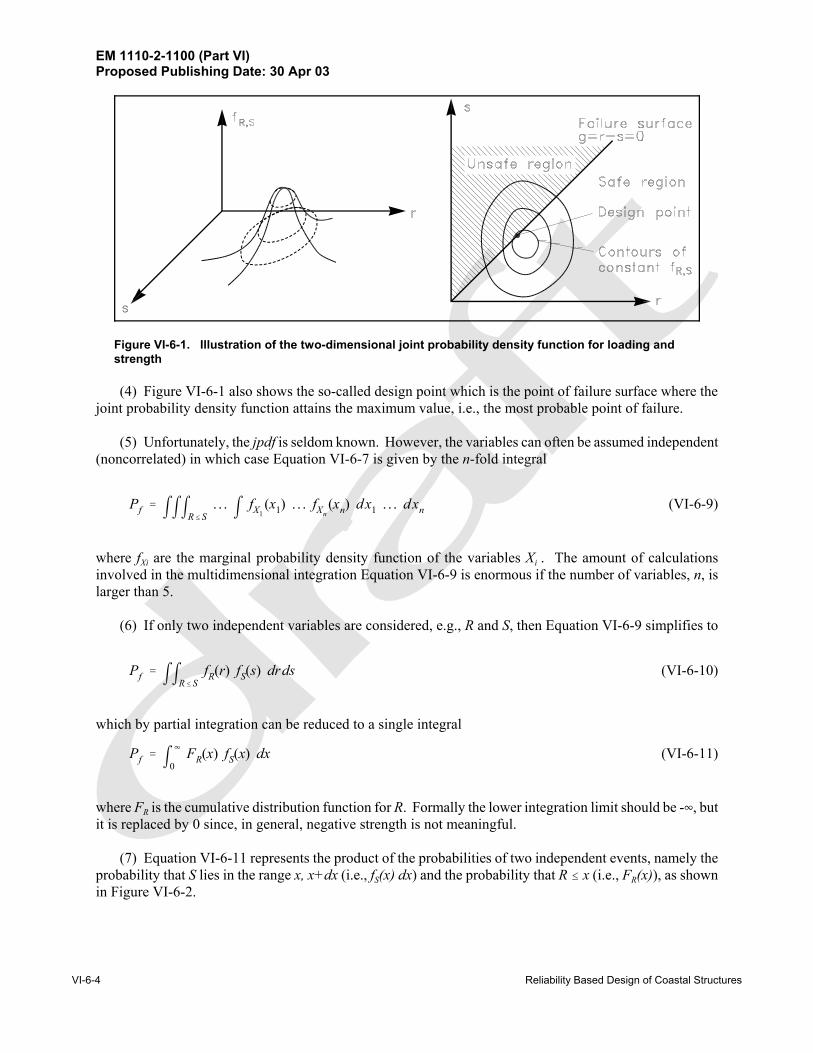
Figure VI-6-1. Illustration of the two-dimensional joint probability density function for loading andstrength
(4) Figure VI-6-1 also shows the so-called design point which is the point of failure surface where thejoint probability density function attains the maximum value, i.e., the most probable point of failure.
(5) Unfortunately, the jpdf is seldom known. However, the variables can often be assumed independent(noncorrelated) in which case Equation VI-6-7 is given by the n-fold integral
(VI-6-9)Pf ' mmmR#S. . . m fX1
(x1) . . . fXn(xn) dx1 . . . dxn
where fXi are the marginal probability density function of the variables Xi . The amount of calculationsinvolved in the multidimensional integration Equation VI-6-9 is enormous if the number of variables, n, islarger than 5.
(6) If only two independent variables are considered, e.g., R and S, then Equation VI-6-9 simplifies to
(VI-6-10)Pf ' mmR#SfR(r) fS(s) drds
which by partial integration can be reduced to a single integral
(VI-6-11)Pf ' m4
0FR(x) fS(x) dx
where FR is the cumulative distribution function for R. Formally the lower integration limit should be -4, butit is replaced by 0 since, in general, negative strength is not meaningful.
(7) Equation VI-6-11 represents the product of the probabilities of two independent events, namely theprobability that S lies in the range x, x+dx (i.e., fS(x) dx) and the probability that R # x (i.e., FR(x)), as shownin Figure VI-6-2.

EM 1110-2-1100 (Part VI)Proposed Publishing Date: 30 Apr 03
Reliability Based Design of Coastal Structures VI-6-5
Figure VI-6-2. Illustration of failure probability in case of two independentvariables, S and R
b. Level II methods. This section gives a short introduction to reliability calculations at Level II. Onlythe so-called first-order reliability method (FORM), where the failure surface is approximated by a tangenthyberplane at some point, is presented. A more accurate method is the second-order reliability method(SORM), which uses a quadratic approximation to the failure surface.
(1) Linear failure functions of normally-distributed random variables.
(a) Assume the loading S(x) and the resistance R(x) for a single failure mode to be statisticallyindependent and with density functions as illustrated in Figure VI-6-2. The failure function is given byEquation VI-6-3 and the probability of failure is expressed by Equation VI-6-10 or Equation VI-6-11.
(b) However, in many cases these functions are not known, but under certain assumptions the functionsmight be estimated using only the mean values and standard deviations. If S and R are assumed to beindependent normally distributed variables with known means and standard deviations, then the linear failurefunction g = R - S is normally distributed with mean value,
(VI-6-12)µg ' µR & µS
and standard deviation
(VI-6-13)σg ' (σ2R % σ2
S )
EM 1110-2-1100 (Part VI)Proposed Publishing Date: 30 Apr 03
VI-6-6 Reliability Based Design of Coastal Structures
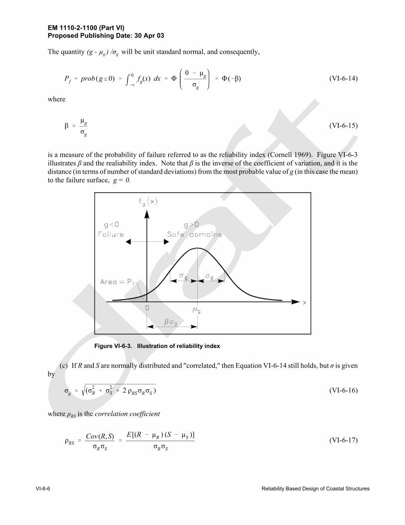
Figure VI-6-3. Illustration of reliability index
The quantity (g - µg ) /σg will be unit standard normal, and consequently,
(VI-6-14)Pf ' prob (g#0) ' m0
&4fg(x) dx ' Φ
0 & µg
σg
' Φ (&β)
where
(VI-6-15)β 'µg
σg
is a measure of the probability of failure referred to as the reliability index (Cornell 1969). Figure VI-6-3illustrates β and the realiability index. Note that β is the inverse of the coefficient of variation, and it is thedistance (in terms of number of standard deviations) from the most probable value of g (in this case the mean)to the failure surface, g = 0.
(c) If R and S are normally distributed and "correlated," then Equation VI-6-14 still holds, but σ is givenby
(VI-6-16)σg ' (σ2R % σ2
S % 2 ρRSσRσS )
where ρRS is the correlation coefficient
(VI-6-17)ρRS 'Cov (R,S)σRσS
'E [(R & µR ) (S & µS )]
σRσS

EM 1110-2-1100 (Part VI)Proposed Publishing Date: 30 Apr 03
Reliability Based Design of Coastal Structures VI-6-7
Figure VI-6-4. Illustration of β in normalized coordinate system
R and S are said to be uncorrelated if ρRS = 0.
(d) In addition to the illustration of β in Figure VI-6-3, a simple geometrical interpretation of β can begiven in the case of a linear failure function g = R - S of the independent variables R and S by atransformation into a normalized coordinate system of the random variables RN = (R - µR ) /σR and SN = (S -µS) /σS , as shown in Figure VI-6-4.
(e) With these variables the failure surface g = 0 is linear and given by
(VI-6-18)R )σR & S )σS % µR & µS ' 0
(f) By geometrical considerations it can be shown that the shortest distance from the origin to this linearfailure surface is equal to in which Equations VI-6-12 and VI-6-13 are used.
(VI-6-19)β 'µg
σg
'µR & µS
σ2R % σ2
S
(2) Nonlinear failure functions of normally-distributed random variables.
(a) If the failure function is nonlinear, then approximate values for µg and σg can be obtainedg ' g (X)by using a linearized failure function. Linearization is generally performed by retaining only the linear termsof a Taylor-series expansion about some point. However, the values of µg and σg , and thus the value of β,depend on the choice of linearization point. Moreover, the value of β defined by Equation VI-6-15 willchange when different, but functionally equivalent, nonlinear failure functions are used.
(b) To overcome these problems, a transformation of the basic variables into aX ' (X1, X2, . . . , Xn )
new set of normalized variables is performed. For uncorrelated normally distributedZ ' (Z1, Z2, . . . , Zn )
basic variables the transformation isX
EM 1110-2-1100 (Part VI)Proposed Publishing Date: 30 Apr 03
VI-6-8 Reliability Based Design of Coastal Structures
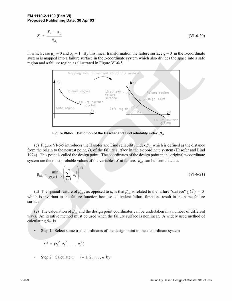
Figure VI-6-5. Definition of the Hasofer and Lind reliability index, βHL
(VI-6-20)Zi 'Xi & µXi
σXi
in which case µZi = 0 and σZi = 1. By this linear transformation the failure surface g = 0 in the x-coordinatesystem is mapped into a failure surface in the z-coordinate system which also divides the space into a saferegion and a failure region as illustrated in Figure VI-6-5.
(c) Figure VI-6-5 introduces the Hasofer and Lind reliability index βHL which is defined as the distancefrom the origin to the nearest point, D, of the failure surface in the z-coordinate system (Hasofer and Lind1974). This point is called the design point. The coordinates of the design point in the original x-coordinatesystem are the most probable values of the variables at failure. βHL can be formulated asX
(VI-6-21)βHL 'min
g ( z )'0
nji'1
z 2i
1/2
(d) The special feature of βHL , as opposed to β, is that βHL is related to the failure "surface" g ( z ) ' 0which is invariant to the failure function because equivalent failure functions result in the same failuresurface.
(e) The calculation of βHL and the design point coordinates can be undertaken in a number of differentways. An iterative method must be used when the failure surface is nonlinear. A widely used method ofcalculating βHL is
• Step 1. Select some trial coordinates of the design point in the z-coordinate system
z d ' (z d1 , z d
2 , . . . , z dn )
• Step 2. Calculate αi i = 1, 2, . . . , n by
EM 1110-2-1100 (Part VI)Proposed Publishing Date: 30 Apr 03
Reliability Based Design of Coastal Structures VI-6-9
αi ' /000MgMzi z' z d
• Step 3. Determine a better estimate of byz d
z di ' αi
nji'1
(αi z di ) & g |z' z d
nji'1
(αi )2
• Step 4. Repeat Steps 2 and 3 to achieve convergence
• Step 5. Evaluate βHL by
βHL '
nji'1
(z di )2
1/2
The method is based on the assumption of the existence of only one minimum. However, several “local”minima might exist. In order to avoid convergence toward a local minima (and thereby overestimationof βHL and the reliability) several different sets of trial coordinates might be tried.
(3) Nonlinear failure functions of non-normal random variables.
(a) It is not always a reasonable assumption to consider the random variables normally distributed. Forexample, parameters characterizing the sea state in long-term wave statistics, such as Hs , will in generalfollow extreme distributions (e.g., Gumbel and Weibull). These distributions are quite different from thenormal distribution and cannot be described using only the mean value and the standard deviation.
(b) For such cases it is still possible to use the reliability index βHL , but an extra transformation of thenon-normal basic variables into normal basic variables must be performed before βHL can be determined aspreviously described.
(c) A commonly used transformation is based on the substitution of the non-normal distribution of thebasic variable Xi by a normal distribution in such a way that the density and distribution functions fXi and FXiare unchanged at the design point.
(d) If the design point is given by , then the transformation readsx d1 , x d
2 , . . . , x dn

EM 1110-2-1100 (Part VI)Proposed Publishing Date: 30 Apr 03
VI-6-10 Reliability Based Design of Coastal Structures
(VI-6-22)
FXi(x d
i ) ' Φx d
i & µ)
X1
σ)Xi
fXi(x d
i ) '1σ)Xi
nx d
i & µ)
X1
σ)Xi
where µNXi and σNXi are the mean and standard deviation of the approximate (fitted) normal distribution.
(e) Equation VI-6-22 yields
(VI-6-23)σ)Xi
'n Φ&1 FXi
(x di )
fXi(x d
i )
µ)
Xi' x d
i & Φ&1 FXi(x d
i ) σ)Xi
(f) Equation VI-6-22 can also be written
FXi(x d
i ) ' Φx d
i & µ)
Xi
σ)Xi
' Φ (z di ) ' Φ (βHL αi )
(g) Solving with respect to xid gives
(VI-6-24)x di ' F &1
Xi[Φ (βHL αi )]
(h) The iterative method presented above for calculation of βHL can still be used if for each step ofiteration the values of µNXi and σNXi given by Equation VI-6-24 are calculated for those variables where thetransformation (Equation VI-6-22) has been used. For correlated random variables the transformation intononcorrelated variables is used before normalization.
(4) Time-variant random variables. The failure functions within breakwater engineering are generallyof the form
(VI-6-25)g ' f1( R ) & f2(Hs , W , Tm )
where represents the resistance variables and Hs , W, and Tm are the load variables signifying the waveRheight, the water level, and the wave period. The random variables are in general time-variant.

EM 1110-2-1100 (Part VI)Proposed Publishing Date: 30 Apr 03
Reliability Based Design of Coastal Structures VI-6-11
(a) Discussion of load variables:
• The most important load parameter in breakwater engineering is the wave height. It is a time-varyingquantity which is best modeled as a stochastic process. Distinction is made between short-term andlong-term statistics of the wave heights. Short-term statistics deal with the distribution of the waveheight H during a stationary sequence of a storm, i.e., during a period of constant Hs (or any othercharacteristic wave height). The short-term wave height distribution follows the Rayleighdistribution for deepwater waves and some truncated distribution in the case of shallow-water waves.
• Long-term statistics deal with the distribution of the storms which are then characterized by themaximum value of Hs occurring in each storm. The storm history is given as the sample (Hs1 , Hs2,... ,Hsn ) covering a period of observation, Y. Extreme-value distributions like the Gumbel and Weibulldistributions are then fitted to the data sample. For strongly depth-limited wave conditions a normaldistribution with mean value as a function of water depth might be appropriate.
• The true distribution of Hs can be approximated by the distribution of the maximum value over Tyears, which is denoted as the distribution of Hs
T. The calculated failure probability then refers tothe period T (which in practice might be the lifetime of the structure) if distribution functions of theother variables in Equation VI-6-25 are assumed to be unchanged during the period T.
• As an example, consider a sample of n independent storms, i.e., Hs1 , Hs2, ... , Hsn , obtained withinY years of observation. Assume that Hs follows a Gumbel distribution given by
(VI-6-26)F(Hs ) ' exp &e &α (Hs & β)
which is the distribution of Hs over a period of Y years with average time span between observations of Y/n.
• The distribution parameters α and β can be estimated from the data using techniques such as themaximum likelihood method or the methods of moments. Moreover, the standard deviations of αand β, signifying the statistical uncertainty due to limited sample size, can also be estimated.
• The sampling intensity is λ = n / Y. Within a T-year reference period the number of data will be λT.The probability of the maximum value of Hs within the period T is then
(VI-6-27)F (H Ts ) ' [F (Hs )]λT ' exp &e &α(Hs & β) λT
• The expectation (mean) value of HsT is given by
(VI-6-28)µ H Ts' β &
1α
ln &ln 1 &1λT
and the standard deviation of HsT (from maximum likelihood estimates) is

EM 1110-2-1100 (Part VI)Proposed Publishing Date: 30 Apr 03
VI-6-12 Reliability Based Design of Coastal Structures
(VI-6-29)
σH Ts'
1nα2
1.109 % 0.514 &ln &ln 1 &1λT
%
% 0.608 &ln &ln 1 &1λT
2 1/2
• Equation VI-6-29 includes the statistical uncertainty due to limited sample size. Some uncertaintyis related to the estimation of the sample values Hs1 , Hs2 , ... , Hsn arising from measurement errors,errors in hindcast models, etc. This uncertainty corresponds to a coefficient of variation σHs /µHs onthe order of 5 - 20 percent. The effect of this might be implemented in the calculations byconsidering a total standard deviation of
(VI-6-30)σ ' σ2H T
s% σ2
Hs
• In Level II calculations, Equation VI-6-27 is normalized around the design point, andEquations VI-6-28 and VI-6-29 or VI-6-30 are used for the mean and the standard deviation.
• Instead of substituting Hs in Equation VI-6-25 with HsT, the following procedure might be used: Set
T in Equations VI-6-27 to VI-6-29 to be 1 year. The outcome of the calculations will then be theprobability of failure in a 1-year period, Pf (1 year). If the failure events of each year are assumedindependent for all variables then the failure probability in T years is
(VI-6-31)Pf (T years) ' 1 & [1 & Pf (1 year)]T
• This assumption simplifies the probability estimation somewhat, and for some structures it isreasonable to assume failure events are independent, e.g., rubble-mound stone armor stability.However, for some resistance variables, such as concrete strength, it is unrealistic to assume theevents of each year are independent. The calculated values of the failure probability in T-years usingHs
1 year and HsT will be different. The difference will be very small if the variability of Hs is much
larger than the variability of other variables.
• The water level W is also an important parameter because it influences the structure freeboard andlimits wave heights in shallow-water situations. Consequently, for the general case it is necessaryto consider the joint distribution of Hs , W, and Tm. However, for deepwater waves W is often almostindependent (except for barometric effects) of Hs and Tm and can be approximated as a noncorrelatedvariable that might be represented by a normal distribution with a certain standard deviation. Thedistribution of W is assumed independent of the length of the reference period T. In shallow water,W will be correlated with Hs due to storm surge effects.
• The wave period Tm is correlated to Hs. As a minimum the mean value and the standard deviationof Tm and the correlation of Tm with Hs should be known in order to perform a Level II analysis.However, the linear correlation coefficient is not very meaningful because it gives an insufficientdescription when the parameters are non-normally distributed. Alternatively the following approachmight be used: From a scatter diagram of Hs and Tm a relationship of the form Tm = A f(Hs) isestablished in which the parameter A follows a normal distribution (or some other distribution) with

EM 1110-2-1100 (Part VI)Proposed Publishing Date: 30 Apr 03
Reliability Based Design of Coastal Structures VI-6-13
mean value µA = 1 and a standard deviation σA which signifies the scatter. Tm can then be replacedby the variable A in Equation VI-6-25. The variable A is assumed independent of all otherparameters.
• Generally, the best procedure for coping with the correlations between Hs , W, and Tm is to work onthe conditional distributions. Assume the distribution of the maximum value of Hs within the periodT is given as F1 (Hs
T). Furthermore, assume the conditional distributions F2 (W |HsT) and F3 (Tm |Hs
T)are known. Let Z1 , Z2 and Z3 be independent standard normal variables and
Φ(z1) ' F1(H Ts )
Φ(z2) ' F2(W |H Ts )
Φ(z3) ' F3(Tm |H Ts )
• The inverse relationships are given by
H Ts ' F &1
1 [Φ(z1)]W ' F &1
2 [Φ(z2) |H Ts ]
Tm ' F &13 [Φ(z3) |H T
s ]
• By converting the resistance variables into standard normal variable , i.e., the resistance termR Zo
is written , then the failure function Equation VI-6-25 becomesf1( R ) ' f3( zo)
g ' f3( zo) & f2 F &11 [Φ(z1)] , F &1
2 [Φ(z2) |H Ts ] , F &1
3 [Φ(z3) |H Ts ] ' 0
• Because g now comprises only independent standard normal variables, the usual iteration methodsfor calculating βHL can be applied.
(b) Discussion of resistance parameters:
• The service life of coastal structures spans anywhere between 20 to 100 years. Over periods of thislength a decrease in the structural resistance is to be expected because of various types of materialdeterioration. Chemical reaction, thermal effect, and repeated loads (fatigue load) can causedeterioration of concrete and natural stone leading to disintegration and rounding of elements. Alsothe resistance against displacements of armor layers made of randomly placed armor units willdecrease with the number of waves (i.e., with time) due to the stochastic nature of the resistance.Consequently, for armor layers this means a reduction over time of the Dn and KD parameters in theHudson equation.
• Although material effects can greatly influence reliability in some cases, they are not easy to includein reliability calculations. The main difficulty is the assessment of the variation with time whichdepends greatly on the intrinsic characteristics of the placed rock and concrete. At this time onlyfairly primitive methods are available for assessment of the relevant material characteristics. In

EM 1110-2-1100 (Part VI)Proposed Publishing Date: 30 Apr 03
VI-6-14 Reliability Based Design of Coastal Structures
Figure VI-6-6. Illustration of a first-passage problem
addition, the variation with time depends very much on the load-history which can be difficult toestimate for the relevant period of structural life.
• Figure VI-6-6 illustrates an example situation representing the tensile strength of concrete armor unitswhere a resistance parameter R(t) decreases with time t. R(t) is assumed to be a deterministicfunction. The load S(t) (the tensile stress caused by wave action) is assumed to be a stationaryprocess. The probability of failure, P(S > R), within a period T is
(VI-6-32)Pf (T) ' 1 & exp &mT
0ν% [R(t)] dt
• where ν+ [R (t)] is the mean-upcrossing rate (number of upcrossings per unit time) of the level R(t)by the process S(t) at time t. ν+ can be computed by Rice's formula
ν% [R(t)] ' m4
R(S & R ) fSS [R(t), S] dS
in which is the joint density function for S(t) and . Implementation of time-variant variables intofSS S(t)Level II analyses is rather complicated. For further explanation, see Wen and Chen (1987).
VI-6-4. Failure Probability Analysis of Failure Mode Systems
a. A coastal structure can be regarded as a system of components which can either function or fail. Dueto interactions between the components, failure of one component may impose failure of another componentand even lead to failure of the system. A so-called fault tree is often used to clarify the relationships betweenthe failure modes.

EM 1110-2-1100 (Part VI)Proposed Publishing Date: 30 Apr 03
Reliability Based Design of Coastal Structures VI-6-15
Figure VI-6-7. Example of simplified fault tree for a breakwater
b. A fault tree describes the relationships between the failure of the system (e.g., excessive wavetransmission over a breakwater protecting a harbor) and the events leading to this failure. Figure VI-6-7shows a simplified example based on some of the failure modes of a rubble-mound breakwater.
c. A fault tree is a simplification and a systematization of the more complete so-calledcause-consequence diagram that indicates the causes of partial failures as well as the interactions between thefailure modes. An example is shown in Figure VI-6-8.
d. The failure probability of the system (for example, the probability of excessive wave transmissionin Figure VI-6-7) depends on the failure probability of the single failure modes and on the correlation andlinking of the failure modes. The failure probability of a single failure mode can be estimated by the methodsdescribed in Part VI-6-3. Two factors contribute to the correlation, namely physical interaction, such assliding of main armor caused by erosion of a supporting toe berm, and correlation through commonparameters like Hs. The correlations caused by physical interactions are not yet quantified. Consequently,only the common-parameter-correlation can be dealt with in a quantitative way. However, it is possible tocalculate upper and lower bounds for the failure probability of the system.
e. A system can be split into two types of fundamental systems, namely series systems and parallelsystems as illustrated by Figure VI-6-9.
(1) Series systems
(a) In a series system, failure occurs if any of the elements i = 1, 2, ... , n fails. The upper and lowerbounds of the failure probability of the system, Pf S are

EM 1110-2-1100 (Part VI)Proposed Publishing Date: 30 Apr 03
VI-6-16 Reliability Based Design of Coastal Structures
Figure VI-6-8. Example of cause-consequence diagram for a rubble-mound breakwater
Figure VI-6-9. Series and parallel systems

EM 1110-2-1100 (Part VI)Proposed Publishing Date: 30 Apr 03
Reliability Based Design of Coastal Structures VI-6-17
Figure VI-6-10. Decomposition of the fault tree into series and parallel systems
(VI-6-33)Upper bound P Uf S ' 1 & (1 & Pf1) (1 & Pf 2) . . . (1 & Pf n)
(VI-6-34)Lower bound P Lf S ' max [Pfi ]
where max [Pf i] is the largest failure probability among all elements. The upper bound corresponds tono correlation between the failure modes and the lower bound to full correlation. Equation VI-6-33 is
sometimes approximated by which is applicable only for small because shouldP Uf S '
nji'1
Pf i Pf i P Uf S
not be larger than 1.
(b) The OR-gates in a fault tree correspond to series components. Series components are dominant inbreakwater fault trees. In fact, the AND-gate shown in Figure VI-6-7 is included for illustration purposes,and in reality it should be an OR-gate.
(2) Parallel systems
(a) A parallel system fails only if all the elements fail.
(VI-6-35)Upper bound P Uf S ' min [Pfi ]
(VI-6-36)Lower bound P Lf S ' Pf1 @ Pf 2 . . . Pf n
(b) The upper bound corresponds to full correlation between the failure modes, and the lower boundcorresponds to no correlation.
• The AND-gates in a fault tree represent parallel components. To calculate upper and lower failureprobability bounds for a system, it is convenient to decompose the overall system into series andparallel systems. Figure VI-6-10 shows a decomposition of the fault tree (Figure VI-6-7).
• To obtain correct Pf S-values it is very important that the fault tree represents precisely the realphysics of the failure development. This is illustrated by Example VI-6-2 where a fault treealternative to Figure VI-6-7 is analyzed. In Example VI-6-2 the same failure mode probabilities asgiven in Example VI-6-1 are used.

EM 1110-2-1100 (Part VI)Proposed Publishing Date: 30 Apr 03
VI-6-18 Reliability Based Design of Coastal Structures
• The real failure probability of the system Pf S will always be in between Pf SU and Pf S
L because somecorrelation exists between the failure modes due to the common loading represented by the sea stateparameters, e.g., Hs .
• It would be possible to estimate Pf S if the physical interactions between the various failure modeswere known and described by formulae, and if the correlations between the involved parameters wereknown. However, the procedure for determining such correlations are complicated and are not yetfully developed for practical use.
• The probability of failure cannot in itself be used as the basis for an optimization of a design.Optimization must be related to a kind of measure (scale), which for most structures is the economy,but can include other measures such as loss of human life.
• The so-called risk, defined as the product of the probability of failure and the economicconsequences, is used in optimization considerations. The economic consequences must cover allkinds of expenses related to the failure in question, i.e., cost of replacement, downtime costs, etc.
VI-6-5. Parameter Uncertainties in Determining the Reliability of Structures
Calculation of reliability or failure probability of a structure is based on formulae describing the structure'sresponse to loads and on information about the uncertainties related to the formulae and relevant parameters.Basically, uncertainty is best given by a probability distribution; but because the true distribution is rarelyknown, it is common to assume a normal distribution and a related coefficient of variation, defined as
(VI-6-37)σ) ' σµ
'standard deviation
mean value
as the measure of the uncertainty. The term "uncertainty" is used in this chapter as a general term referringto errors, to randomness, and to lack of knowledge.
a. Uncertainty related to failure mode formulae.
The uncertainty associated with a formula can be considerable. This is clearly seen from many diagramspresenting the formula as a smooth curve shrouded by a wide scattered cloud of data points (usually fromexperiments) that are the basis for the curve fitting. Coefficients of variation of 15 - 20 percent or even largerare quite normal. The range of validity and the related coefficient of variation should always be consideredwhen using a design formula.
b. Uncertainty related to environmental parameters.
The sources of uncertainty contributing to the total uncertainties in environmental design values arecategorized as follows:
(1) Errors related to instrument response (e.g., from accelerometer buoy and visual observations).
(2) Variability and errors due to different and imperfect calculations methods (e.g., wave hindcastmodels, algorithms for time-series analysis).

EM 1110-2-1100 (Part VI)Proposed Publishing Date: 30 Apr 03
Reliability Based Design of Coastal Structures VI-6-19
P Uf S ' 1 & (1 & Pf 6) (1 & Pf 1) (1 & Pf 5) (1 & Pf 2) (1 & min [Pf 3, Pf 4]) ' 12.9%
P Uf S ' Pf 6 % Pf 1 % Pf 5 % Pf 2 % min [Pf 3, Pf 4]) ' 13.5%
P Lf S ' max [Pf 6 , Pf 1 , Pf 5 , Pf 2 , (Pf 3 @ Pf 4)] ' 6%
EXAMPLE PROBLEM VI-6-1
The Level II analysis of the single failure modes for a specific breakwater schematized in FigureVI-6-10 revealed the following probabilities of failure in a 1-year period
i 1 2 3 4 5 6
Pf i % 3 6 4 3 0.5 1
Note that these Pf i-values cannot be used in general because they relate to a specific structure. However, they are typical for conventionally designed breakwaters with respect to order of magnitudeand large variations.
The simple failure probability bounds for the system are given by Equations VI-6-33, VI-6-34,VI-6-35, and VI-6-36:
Upper bound (no correlation):
or alternately for small values of Pf i
Lower bound (full correlation):
The simple bounds corresponding to T-years structural life might be approximated by the use ofEquation VI-6-311
Structure life in years
20 50 100
PfsU % 94 100 100
PfsL %1 71 95 100
(Continued on next page)

EM 1110-2-1100 (Part VI)Proposed Publishing Date: 30 Apr 03
VI-6-20 Reliability Based Design of Coastal Structures
P LfS '
maxi'1&n [Pfi]
EXAMPLE PROBLEM VI-6-1 (Concluded)
1 It is very important to notice that the use of Equation VI-6-31, which assumes independent failureevents from one year to another, can be misleading. This will be the case if some of the parameterswhich contribute significantly to the failure probability are time-invariant, i.e., are not changed fromyear to year. An example would be the parameter signifying a large uncertainty of a failure modeformula, such as the parameter A in Equation VI-6-2. If all parameters were time-invariant then thecorrect lower bound would be
independent of T, i.e., 6% for all T in the example. It follows that use of Equation VI-6-31 results invalues of Pf S
L for T > 1 year that are too large.
Figure VI-6-11. Example of simplified fault tree for a breakwater
(3) Statistical sampling uncertainties due to short-term randomness of the variables (variability withina stochastic process, e.g., two 20-min. records from a stationary storm will give two different values of thesignificant wave height)
(4) Choice of theoretical distribution as a representative of the unknown long-term distribution (e.g., aWeibull and a Gumbel distribution might fit a data set equally well but can provide quite different values fora 200-year event).
(5) Statistical uncertainties related to extrapolation from short samples of data sets to events of lowprobability of occurrence.

EM 1110-2-1100 (Part VI)Proposed Publishing Date: 30 Apr 03
Reliability Based Design of Coastal Structures VI-6-21
P Uf S ' 1 & (1 & Pf 6) (1 & min [Pf 1 , Pf 5]) [Pf 1, Pf 2, Pf 3, Pf 4] ' 4.5%
P Uf S ' Pf 6 % min [Pf 1 , Pf 5] % min [Pf 1, Pf 2, Pf 3, Pf 4] ' 4.5%
P Lf S ' max [Pf 6 , (Pf 1 @ Pf 5 ) , (Pf 1 @ Pf 2 @ Pf 3 @ Pf 4)] ' 1%
EXAMPLE PROBLEM VI-6-2
Figure VI-6-11 shows a fault tree that differs from the fault tree in Figure VI-6-7. In Figure VI-6-11only failure mode 6 can directly cause system failure, whereas in Figure VI-6-7 each of the failuremodes 6, 5, 1, 2 and (3+4) can cause system failure.
The decomposition of the fault tree is shown in two steps in Figure VI-6-12. Note that the samefailure mode can appear more than once in the decomposed system.
The simple bounds for the system are given by Equations VI-6-33, VI-6-34, VI-6-35, and VI-6-36:
Upper bound:
or for smaller values of Pf i
Lower bound:
Using the same Pf i -values and procedure as given in Example VI-6-1 the following system failureprobabilities are obtained
Structure life in years
20 50 100
PfsU % 60 90 99
PfsL %1 18 39 63
These values are quite different from the values of Example VI-6-1 which emphasizes the importanceof a correct fault tree. 1 See note in Example VI-6-1.

EM 1110-2-1100 (Part VI)Proposed Publishing Date: 30 Apr 03
VI-6-22 Reliability Based Design of Coastal Structures
Figure VI-6-12. Decomposition of the fault tree into series and parallel systems
(6) Statistical vagaries of the elements.
(a) Distinction must be made between short-term sea state statistics and long-term (extreme) seastatistics. Short-term statistics are related to the stationary conditions during a sea state, e.g., wave heightdistribution within a storm of constant significant wave height, Hs. Long-term statistics deal with the extremeevents, e.g., the distribution of Hs over many storms.
(b) Related to the short-term sea state statistics the following aspects must be considered:
• The distribution for individual wave heights in a record in deepwater and shallow-water conditions,i.e, Rayleigh distribution and some truncated distributions, respectively.
• Variability due to short samples of single peak spectra waves in deep and shallow water based ontheory and physical simulations.

EM 1110-2-1100 (Part VI)Proposed Publishing Date: 30 Apr 03
Reliability Based Design of Coastal Structures VI-6-23
• Variability due to different spectral analysis techniques, i.e., different algorithms, smoothing andfilter limits.
• Errors in instrument response and influence of measurement location. For example, floatingaccelerometer buoys tend to underestimate the height of steep waves. Characteristics ofshallow-water waves can vary considerably in areas with complex seabed topography. Waverecordings at positions with depth-limited breaking waves cannot produce reliable estimates of thedeepwater waves.
• Imperfection of deep and shallow-water numerical hindcast models and quality of wind input data.
(c) Estimates of overall uncertainties for short-term sea state parameters (first three items) are presentedin Table VI-6-1 for use when more precise site specific information is not available.
Table VI-6-1 Typical Variational Coefficients σN = σ /µ (standard deviation over mean value) for Measured and Calculated Sea StateParameters (Burcharth 1992)
Parameter Methods of DeterminationEstimated Typical Values
CommentsσN BiasSignificant wave height,OFFSHORE
Significant wave heightNEARSHORE determinedfrom offshore significant waveheight accounting for shallow-water effects
Accelerometer buoy, pressure cell,vertical radar
Horizontal radar
Hindcast numerical models
Hindcast, SMB method
Visual observations from ships
Numerical models
Manual calculations
0.05 - 0.1
0.15
0.1 - 0.2
0.15 - 0.2
0.2
0.1 - 0.20
0.15 - 0.35
-0
-0
0 - 0.1
?
0.05
0.1
Very dependent on qualityof weather maps
Valid only for stormconditions in restricted seabasins
σN can be much larger insome cases
Mean wave period offshoreon condition of fixedsignificant wave height
Accelerometer buoy
Estimates from ampl. Spectra
Hindcast, numerical models
0.02 - 0.05
0.15
0.1 - 0.2
-0
-0
-0Duration of sea state withsignificant wave heightexceeding a specific level
Direct measurements
Hindcast numerical models
0.02
0.05 - 0.1
-0
-0Spectral peak frequencyoffshore
Measurements
Hindcast numerical models
0.05 - 0.15
0.1 - 0.2
-0
-0Spectral peakedness offshore Measurements and hindcast
numerical models 0.4 -0
Mean direction of wavepropagation offshore
Pitch-roll buoy
Measurements η, u, v orp, u, v 1
Hindcast numerical models
5 degrees
10 degrees
15 - 30 degreesAstronomical tides Prediction from constants 0.001 - 0.07 -0Storm surge Numerical models 0.1 - 0.25 ±0.11 Two horizontal velocity components and water-level elevation or pressure.

EM 1110-2-1100 (Part VI)Proposed Publishing Date: 30 Apr 03
VI-6-24 Reliability Based Design of Coastal Structures
(d) Evaluation of the uncertainties related to the long-term sea state statistics, and use of these estimatesfor design, involves the following considerations:
• The encounter probability.
• Estimation of the standard deviation of a return-period event for a given extreme distribution.
• Estimation of extreme distributions by fitting to data sets consisting of uncorrelated values of Hs from
- Frequent measurements of Hs equally spaced in time.
- Identification of the largest Hs in each year (annual series).
- Maximum values of Hs for a number of storms exceeding a certain threshold value of Hsusing peak over threshold (POT) analysis.
The methods of fitting are the maximum likelihood method, the method of moments, the least squaremethod, and visual graphical fit.
• Uncertainty on extreme distribution parameters due to limited data sample size.
• Influence on the extreme value of Hs on the choice of threshold value in the POT analysis. (Thethreshold level should exclude all waves which do not belong to the statistical population of interest).
• Errors due to lack of knowledge about the true extreme distribution. Different theoreticaldistributions might fit a data set equally well, but might provide quite different return period valuesof Hs . (The error can be estimated only empirically by comparing results from fits to differenttheoretical distributions).
• Errors due to applied plotting formulae in the case of graphical fitting. Depending on the appliedplotting formulae quite different extreme estimates can be obtained. The error can only beempirically estimated.
• Climatological changes.
• Physical limitations in extrapolation to events of low probability. The most important example mightbe limitations in wave heights due to limited water depths and fetch restrictions.
• The effect of measurement error on the uncertainty related to an extreme event.
(e) It is beyond the scope of this chapter to discuss in more detail the mentioned uncertainty aspectsrelated to the environmental parameters. Additional information is given in Burcharth (1992).

EM 1110-2-1100 (Part VI)Proposed Publishing Date: 30 Apr 03
Reliability Based Design of Coastal Structures VI-6-25
c. Uncertainty related to structural parameters.
The uncertainties related to material parameters (such as density) and geometrical parameters (such as slopeangle and size of structural elements) are generally much smaller than the uncertainties related to theenvironmental parameters and to the design formulae.
VI-6-6. Partial Safety Factor System for Implementating Reliability in Design
a. Introduction to partial safety factors.
(1) The objective of using partial safety factors in design is to assure a certain reliability of the structures.This section presents the partial safety factors developed by the Permanent International Association ofNavigation Congresses (PIANC) PTCII Working Group 12 (Analysis of Rubble-Mound Breakwaters) andWorking Group 28 (Breakwaters with Vertical and Inclined Concrete Walls), Burcharth (1991) and Burcharthand Sørensen (1999).
(2) The partial safety factors, γi , are related to characteristic values of the stochastic variables, Xi,ch . Inconventional civil engineering codes the characteristic values of loads and other action parameters are oftenchosen to be an upper fractile (e.g., 5 percent), while the characteristic values of material strength parametersare chosen to be a lower fractile. The values of the partial safety factors are uniquely related to the applieddefinition of the characteristic values.
(3) The partial safety factors, γi , are usually larger than or equal to 1. Consequently, if we define thevariables as either load variables Xi
load (for example Hs ) or resistance variables Xires (for example the block
volume) then the related partial safety factors should be applied as follows to obtain the design values:
(VI-6-38)
X designi ' γload
i @ X loadi,ch
X designi '
X resi,ch
γresi
(4) The magnitude of γi reflects both the uncertainty of the related parameter Xi , and the relativeimportance of Xi in the failure function. A large value, e.g., γHs = 1.4, indicates a relatively large sensitivityof the failure probability to the significant wave height, Hs . On the other hand, γ • 1 indicates little ornegligible sensitivity, in which case the partial coefficient should be omitted. Bear in mind that the magnitudeof γi is not (in a mathematical sense) a stringent measure of the sensitivity of the failure probability of theparameter, Xi .
(5) As an example, when partial safety factors are applied to the characteristic values of the parametersin Equation VI-6-2, a design equation is obtained, i.e., the definition of how to apply the coefficients. Thepartial safety factors can be related either to each parameter or to combinations of the parameters (overallcoefficients). The design equation obtained when partial safety factors are applied to each parameter is givenby

EM 1110-2-1100 (Part VI)Proposed Publishing Date: 30 Apr 03
VI-6-26 Reliability Based Design of Coastal Structures
(VI-6-39)
G 'Ach
γA
∆ch
γ∆
Dn,ch
γDn
KDcot αch
γcot α
1/3
& γHsHs,ch $ 0
or
Dn,ch $ γAγ∆γDnγ1/3
cotαγHs
Hs,ch
Ach∆ch KD cotαch
(6) If the partial safety factors are applied to combinations of parameters, there may be only γHs and anoverall coefficient γZ related to the first term on the right-hand side of Equation VI-6-39. The design equationwould then become
(VI-6-40)
G 'Ach
γZ
∆ch Dn,ch KD cot α 1/3 & γHsHs,ch $ 0
or
Dn,ch $ γZγHs
Hs,ch
Ach∆ch KD cotαch1/3
(7) Equations VI-6-39 and VI-6-40 express two different "code formats." By comparing the twoequations it is seen that the product of the partial coefficients is independent of the chosen format if the otherparameters are equal. A goal is to have a system which is as simple as possible, i.e., with as few partial safetyfactors as possible, but without invalidating the accuracy of the design equation beyond acceptable limits.Fortunately, it is often possible to use overall coefficients, such as γA in Equation VI-6-40, without losingsignificant accuracy within the realistic range of parameter value combinations. This is the case for the partialsafety factors system presented in this chapter where only two partial safety factors, γHs and γZ , are used ineach design formula.
(8) Usually several failure modes are relevant to a particular design. The relationship between the failuremodes are characterized either as series systems or parallel systems. A fault tree can be used to illustrate thecomplete system. The partial safety factors for failure modes associated with a system having a failureprobability, Pf , are different from the partial safety factors for single failure modes having the same failureprobability, Pf . Therefore, partial safety factors for single failure modes and multifailure mode systems mustbe treated separately.
b. Uncertainties and statistical models.
Uncertainties in relation to rubble-mound breakwaters can be divided in uncertainties related to the followingthree groups:
• Load uncertainties (wave modeling).
• Soil strength uncertainties (modeling of soil strength parameters).
• Model uncertainties (both wave load models and models for bearing capacity of the foundation).

EM 1110-2-1100 (Part VI)Proposed Publishing Date: 30 Apr 03
Reliability Based Design of Coastal Structures VI-6-27
(1) Wave modeling.
(a) For calibration of partial safety factors the maximum significant wave height in T years is denotedas , and it is modeled (for example) by the extreme Weibull distribution, given asFH T
s
(VI-6-41)FH TS
(Hs) ' 1 & exp &Hs & H )
s
β
αλT
where λ is the number of observations per year, HSN is the threshold level, and α and β are the Weibulldistribution parameters.
(b) For calibration of the PIANC partial safety factor system, wave data from four quite differentgeographical locations were selected as presented in Table VI-6-2. In Table VI-6-2, N is the number of datasamples and h is the water depth in meters.
Table VI-6-2Wave Data from Different Locations Fitted to a Weibull Distribution (β, HSN and h are in meters)
N λ α β (m) HSN (m) h (m)
Bilbao 50 4.17 1.39 1.06 4.9 25
Sines 15 1.25 1.78 2.53 7.1 25
Tripoli 15 0.75 1.83 3.24 2.9 25
Fallonica 46 5.94 1.14 0.58 2.7 10
(c) The wave data from Bilbao, Sines and Tripoli correspond to deepwater waves, whereas the wave datafrom Fallonica corresponds to shallow-water waves. To model the statistical uncertainty, α and β are modeledas independent and normally distributed.
(d) The model uncertainty related to the quality of the measured wave data is modeled by a multiplicativestochastic variable FHs which is assumed to be normally distributed with expected value 1 and standarddeviation . High quality and low quality wave data could be represented by = 0.05 and 0.2,σ)Fhs
σ)FHs
corresponding to accelerometer buoy and fetch diagram estimates, respectively, as given by Table VI-6-1.
(2) Soil strength modeling.
(a) Statistical modeling of the soil strength (sand and/or clay) is generally difficult, and only few modelsare available in the literature that can be used for practical reliability calculations. In general the materialcharacteristics of the soil have to be modeled as a stochastic field. The parameters describing the stochasticfield have to be determined on the basis of the measurements which are usually performed to characterize thesoil characteristics. Because these measurements are only performed in a few locations, statistical uncertaintydue to the sparse data is introduced, and this uncertainty must be included in the statistical model.Furthermore, the uncertainty in the determination of the soil properties and the measurement uncertainty mustalso be included in the statistical model.

EM 1110-2-1100 (Part VI)Proposed Publishing Date: 30 Apr 03
VI-6-28 Reliability Based Design of Coastal Structures
(b) Because breakwaters are composed of loose material in frictional contact, and it is assumed that thefoundation failure modes are developed in the core; only statistical models for the effective friction angle andthe angle of dilation are needed. Usually these angles are modeled by normal or lognormal distributions.
(c) The bearing capacities related to the geotechnical failure modes are estimated using the upper boundtheorem of classical plasticity theory where an associated flow rule is assumed. However, the friction angleand the dilation angle for the rubble-mound material and the sand subsoil are usually different. Therefore,in order to use the theory based on an associated flow rule, the following reduced effective friction angle ndis used (Hansen 1979):
(VI-6-42)tan nd 'sinn) cosψ
1 & sinn) sinψ
where nN is the effective friction angle and ψ is the dilation angle.
(3) Model uncertainties.
(a) In general, model uncertainties related to a given mathematical model can be evaluated on the basisof:
• Comparisons between experimental tests/measurements and numerical model calculations.
• Comparisons between numerical calculations with the given mathematical model and a moreadvanced/complex model.
• Expert opinions.
• Information from the literature.
(b) Many laboratory experiments have been performed for most of the failure modes related to hydraulicinstability of the armor layer. Based on these experiments the model uncertainty can be estimated. Modeluncertainty connected with extrapolation from laboratory to a real structure can be judged on the basis ofexpert opinions, information from the literature, and observations of similar existing structures.
(c) For soil strength models no similar measurements models are available. However, if “simple”rotation and translation failure models based on the upper bound theorem of plasticity theory are used, thenthese can be evaluated by comparison with results from more refined numerical calculations using nonlinearfinite element programs. Estimates of the model uncertainties can thus be obtained.
c. Format for partial safety factors.
(1) The PIANC partial safety factors are calibrated with the following input:
• Design lifetime TL (= 20, 50 or 100 years).
• Acceptable probability of failure Pf (= 0.01, 0.05, 0.10, 0.20, or 0.40).
• Coefficient of variation = (0.05 and 0.20).σ)FHs

EM 1110-2-1100 (Part VI)Proposed Publishing Date: 30 Apr 03
Reliability Based Design of Coastal Structures VI-6-29
• Deep or shallow-water conditions.
• Wave loads determined with or without hydraulic model tests.
(2) The partial safety factors are as follows:
• A load partial safety factor γP to be applied to the mean value of the permanent load (= 1).
• A load partial safety factor γH to be applied to (the central estimate of the significant waveHTLs
height which, in average, is exceeded once every TL years).
• A partial safety factor to be used to the combination of the mean values of the resistance variablesas shown in the design equation. γZ is to be used with friction materials in rubble-mound and/orsubsoils (tangent to the mean value of the friction angle is divided by γZ ).
• A partial safety factor γC to be used with the mean value of the undrained shear strength of claymaterials in the subsoil (the mean value of the undrained shear strength is divided by γC ).
d. Tables of partial safety factors.
(1) Partial safety factors are presented as follows:
Table VI-6-3Partial Safety Factor Tables
Structure Failure Armor Table(s)
Rubble-mound structures
Armor stability
Rocks VI-6-4 - VI-6-6Cubes VI-6-7Tetrapods VI-6-8Dolosse VI-6-9 & VI-6-10Hollowed Cubes VI-6-11 & VI-6-12
Toe berm VI-6-13
BreakageDolosse VI-6-14 & VI-6-15Tetrapods VI-6-16
RunupRock VI-6-17Hollowed Cubes VI-6-18Dolosse VI-6-19
Scour VI-6-20 & VI-6-21
Vertical-wall caissonstructures
Foundation: sand subsoil VI-6-22Foundation: clay subsoil VI-6-23Sliding failure VI-6-24Overturning failure VI-6-25Scour VI-6-26Toe berm VI-6-27
(2) In the case of vertical walls, wave forces are calculated from the Goda formula. Furthermore, thefollowing factors are used to compensate for the positive bias inherent in the Goda formula (seeTable VI-5-55):

EM 1110-2-1100 (Part VI)Proposed Publishing Date: 30 Apr 03
VI-6-30 Reliability Based Design of Coastal Structures
������ ������ �� � ����� ��������
� ��
���� ������ ���� ����� � �� ���
� �������
�
���� ��� �
���� �
�� �� �� �� ������ ��� ��� �� ����
���� �� ���� ��� ���
���� �� ��� �� ����
�� � �� ��� �� ������� ��� ���� ��� ����
= 0.90, bias factor to be applied to the Goda horizontal wave forceUHor. Force
= 0.77, bias factor to be applied to the Goda vertical wave forceUVer. Force
= 0.81, bias factor to be applied to the moment from the Goda horizontal wave forcesUHor. Moment
around the shoreward heel of the base plate
= 0.72, bias factor to be applied to the moment from the Goda vertical wave forces aroundUVer. Moment
the shoreward heel of the base plate
A “hat” ( ^ ) over the variable indicates a mean value.
(3) Part VI-7, “Design of Specific Project Elements,” contains worked design examples for the mostcommon coastal structures. Some of these examples include a reliability analysis based on the informationcontained in Tables VI-6-4 to VI-6-27 either as part of the design or as an alternative to deterministic methodsbased on a single return period of occurrence. The Part VI-7 examples provide coastal engineers withguidance on selection of partial safety factors γHs and γZ for various levels of Pf and .σ)FHs
Table VI-6-4Partial Safety Factors for Stability Failure of Rock Armor, Hudson Formula, Design Without Model Tests

EM 1110-2-1100 (Part VI)Proposed Publishing Date: 30 Apr 03
Reliability Based Design of Coastal Structures VI-6-31
������ ������ �� � ����� ��������
� ��
����� ����� �� ���� �� ���
�� ���� ���� ���������� ������� � �� � �
� ������
�� � �� ������ � ��� �� �� � �� �� ��� �� �� � �� ����� ���
�� ��
����� �� ����
�
������
������ ���� �����
� ���
� �� �� �� ������ ��� ��� �� ����
���� �� ���� ��� ����
���� ��! ���� ��! ����
���� ��� ���� ��� ����
��� ��� ���� ��� ����
������ ������ �� � ����� ��������
� ��
������� ������� �� ���
�� ����� ������� ����������� ������
� � �� ��� �������
�� �
�� ��
� �� � ����
�
�������
�� ��� � � �� ��
� � �
�� �� �� �� ������ ��� ���� ��� ����
��� ��� ���� ��� ����
���� ��� ���� �� ������� ��� ���� ��� ����
��� ��� ���� ��� ����
Table VI-6-5Partial Safety Factors for Stability Failure of Rock Armor, Plunging Waves, van der Meer Formula, Design Without ModelTests
Table VI-6-6Partial Safety Factors for Stability Failure of Rock Armor, Surging Waves, van der Meer Formula, Design Without ModelTests

EM 1110-2-1100 (Part VI)Proposed Publishing Date: 30 Apr 03
VI-6-32 Reliability Based Design of Coastal Structures
������ ������ �� � ����� ��������
� ��
��
����
� ��������
� �������� ���
�������
���� � ��� � �� ��� ��������
����� ��� ����
� ���
�� �� �� �� ������ �� ���� ��� ����
��� ��� ���� �� ����
���� ��� ���� ��� ����
���� ��� ���� ��� ����
���� ��� ���� ��� ����
������ ������ �� � ����� ��������
� ��
��
�����
� ��������
� ��������� ��
�������
���� �� ��� � �� ��� �� ������
����� �� ����
� ��
�� �� �� �� ���� ��� ��� ��� ���
�� ��� ��� ��� ��
�� ��� ��� ��� ���
�� ��� ��� ��� ��
�� �� �� ��� ��
Table VI-6-7Partial Safety Factors for Stability Failure of Cube Block Armor, van der Meer Formula, Design Without Model Tests
Table VI-6-8Partial Safety Factors for Stability Failure of Tetrapods, van der Meer Formula, Design Without Model Tests

EM 1110-2-1100 (Part VI)Proposed Publishing Date: 30 Apr 03
Reliability Based Design of Coastal Structures VI-6-33
������ ������ �� � ����� ��������
� ��
���� ������� ����� �� ����� ������
� � �� ���� �������
������ � � �����
� ��
�� �� �� �� � � ��� �� � ��� �� �
� � ��� �� ��� �� �
�� ��� �� ��� ��
�� ��� �� ��� �� � �� �� ��� ��� �� �
Table VI-6-9Partial Safety Factors for Stability Failure of Dolosse, Without Superstructure, Burcharth Formula, Design WithoutModel Tests
EM 1110-2-1100 (Part VI)Proposed Publishing Date: 30 Apr 03
VI-6-34 Reliability Based Design of Coastal Structures
������ ������
� ��
���� ������� ����� �� ����� ������
� � �� ���� �������
������ ��� �����
� ���
�� �� �� ������ ��� ���� ��� ������� ��� ���� ��� �������� ��� ���� �� �������� ��� ���� ��� �������� ��� ���� ��� ����
�� ���������� ���� ������ ���� ������ ���� !
� "�## !��#��$ % � ������
�� "�## !��#��$ % �����
� ��&���� �
�� '(����)��� ��*� )�����+ ����+ )����� % ��*� ���� ��� #�,� � )�,��# - ) ##�
� - ) # ���#� ����
� .��/��� !��#��$
� 0�)����� ��,*�� % ����# ������ )���)# �12 � �� �� !�#3�)���! �� - ) # ������ + � , �� �����+ % � �4 !�#�)���,�����#��� � � �����
�� 5�,*�� % ����#� 6 � �� � ���� �#� �� � ����
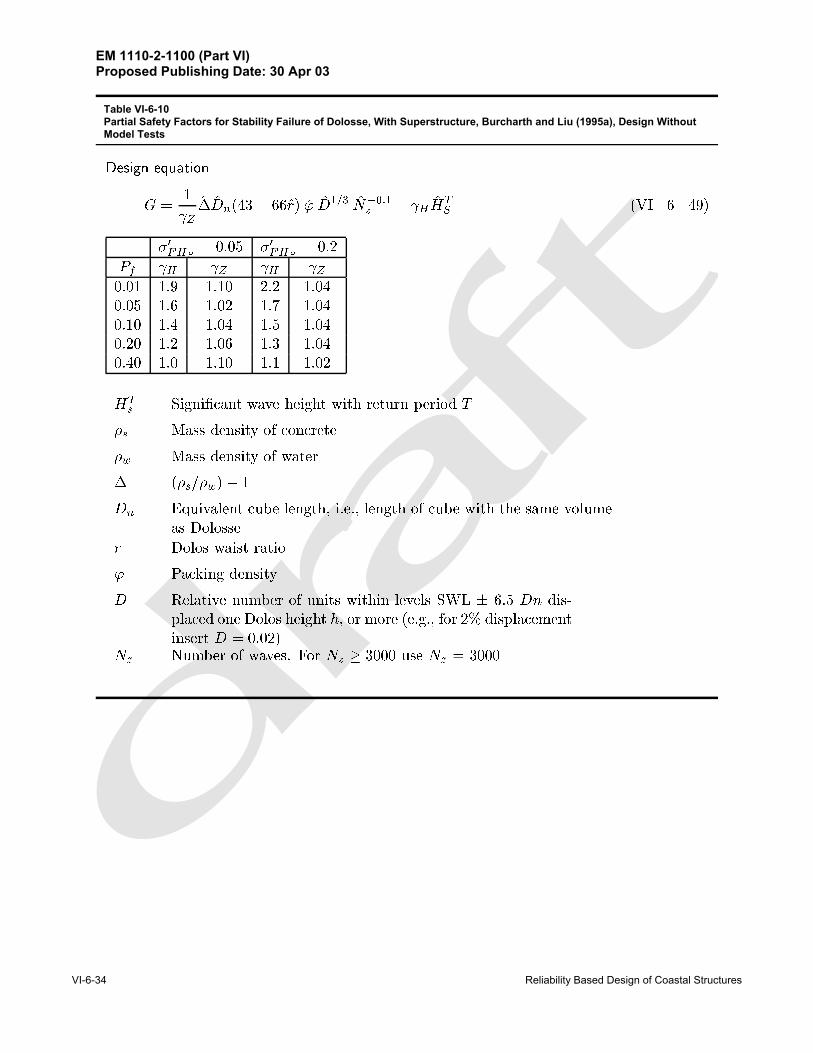
Table VI-6-10Partial Safety Factors for Stability Failure of Dolosse, With Superstructure, Burcharth and Liu (1995a), Design WithoutModel Tests

EM 1110-2-1100 (Part VI)Proposed Publishing Date: 30 Apr 03
Reliability Based Design of Coastal Structures VI-6-35
������ ������
� ��
��������� ���� � ��� �����
�� � � ��� � �� ���� ����� ��
�����
��� � ���� ��� ����������
����� ��� ����
� ���
�� �� �� ������ �� ���� �� ������� ��� ���� �� �������� ��� ���� ��� �������� ��� ���� �� �������� ��� ���� ��� ����
��� ���������� ���� ������ ���� ��� �� !���"# �
�� $�%% #��%��& "' �"������
�� $�%% #��%��& "' �����
���(���� �
�� )* ���+��� � ,� +�����- ����- +����� "' � ,� ���� ��� %�.� �"+ .��% /"+"%%�
��� 0 .,�� "' #�%!+���# ���% ������ � %���! ��#�� "' "�� �* ���+���� ,� +����� ��
Table VI-6-11Partial Safety Factors for Stability Failure of Trunk of Hollowed Cubes, Slope 1:1.5 and 1:2, Berenguer and Baonza(1995), Design Without Model Tests

EM 1110-2-1100 (Part VI)Proposed Publishing Date: 30 Apr 03
VI-6-36 Reliability Based Design of Coastal Structures
������ ������
� ��
������ � ��� ������ ������
� � �� ��� � �� ���� �������
� ���
��� � ����� ������������
������ ���� �����
� ���
� �� �� �� ������ ��� ���� ��� �������� ��� ���� ��� �������� ��� ���� ��� �������� ��� ���� ��� �������� ��� ���� ��� ����
�� ���������� ���� ��� � ��� ������ ���!"
� #�$$ "��$��% !& �!������
�� #�$$ "��$��% !& �����
� ��'���� �
�� ()����*��� ��+� *���� , ����, *���� !& ��+� ��� � � $�-� �!*�-��$ .!*!$$�
� /�*����� ��-+�� !& "�$ *���" ����$
�� 0��� $��� ��$$, �������� .�� ����� ���� *���� �!���$ !�"��� �! ��1 ���� ���!"
Table VI-6-12Partial Safety Factors for Stability Failure of Roundhead of Hollowed Cubes, Slope 1:1.5 and 1:2, Berenguer and Baonza(1995), Design Without Model Tests

EM 1110-2-1100 (Part VI)Proposed Publishing Date: 30 Apr 03
Reliability Based Design of Coastal Structures VI-6-37
������ ������ �� � ����� ��������
� ��
������
��������
� ��� � �������� �� ��� � �� ���
� ������
��
��� ���� ��
��� ��
� �� �� �� ������ ��� ���� ��� ����
���� ��� ���� ��� ����
���� ��� ��� ��� ����
�� � ��� ���� �� ����
���� ��� ���� ��� ����
������ ������ �� � ����� ��������
� ��
��� � ��
���� �����
��� ���� �
�� ��������
��
���� �� ��
���� ��
� �� �� �� ���� �� �� ��� ��
�� ��� ��� ��� ���
�� ��� �� ��� ��
�� ��� ��� �� ��
�� ��� �� ��� ���
Table VI-6-13Partial Safety Factors for Stability Failure of Toe Berm, Parallelepiped Concrete Blocks and Rocks., Burcharth Formula, Design Without Model Tests
Table VI-6-14Partial Safety Factors for Trunk Dolos Breakage, Burcharth Formula, Design Without Model Tests

EM 1110-2-1100 (Part VI)Proposed Publishing Date: 30 Apr 03
VI-6-38 Reliability Based Design of Coastal Structures
������ ������ �� � ����� ��������
� ��
��� � ����� ������� ���
�������� ���
� ����� �������
������ ���� �����
� ���
�� �� �� �� ������ �� ���� ��� �������� ��� ���� �� ����
���� ��� ��� ��� ���
���� ��� ���� ��� ����
���� ��� ���� ��� ����
������ ������ �� � ����� ��������
� ��
��� � ���������� ������� ���
�������� ���
� ����� �������
������ ���� �����
� ���
�� �� �� �� ��� �� � � � �� � � � �
� �� � � �� � � � ��
� �� � � � �� � � � ��
� �� � � � �� � � � �� �� � � � �� � � � ��
Table VI-6-15Partial Safety Factors for Roundhead Dolos Breakage, Burcharth Formula, Design Without Model Tests
Table VI-6-16Partial Safety Factors for Trunk Tetrapod Breakage, Burcharth Formula, Design Without Model Tests

EM 1110-2-1100 (Part VI)Proposed Publishing Date: 30 Apr 03
Reliability Based Design of Coastal Structures VI-6-39
������ ������
��� �� � ���� �������������� �� ����� � � ��
� ��
���� ���� ��� ������������ � � ���
� �� �����
����� ��� ����
� ���
� � � � ����� ��� ���� ��� ������� ��� ���� ��� �������� ��� ���� ��� �������� ��� ���� ��� �������� ��� ���� ��� ����
��� �� � ���� ������������� � �� ����� � � ����
� ��
����
�������� �� ���������� � � ���� �� �����
����� ��� ����
� ���
� � � � ����� �� ���� ��� ������� ��� ���� ��� �������� ��� ���� ��� �������� ��� ���� ��� �������� ��� ���� ��� ����
��� ��������� ���������� � � ��� �!� ����� �"�"� �# �� "� $"%�& �' ����� � �
� ����� �������� ��� ������� ��������� �������� ��� ������ ������������ �� ���� ��� �������� ��� �����
��� ���������� ��� ������ ���� ������ ������ �
� ���������� ������������� ��� ������ ��� �!!
����� �� � � �� ���������
�"�������� ����������� #$% � � � �&�! !�!' !�() &� '� *' &�+, !�!- &�), !�+-���������� &�-' &�** &�)! !�(
Table VI-6-17Partial Safety Factors for Runup, Rock Armored Slopes, De Waal and van der Meer (1992), Design Without Model Tests

EM 1110-2-1100 (Part VI)Proposed Publishing Date: 30 Apr 03
VI-6-40 Reliability Based Design of Coastal Structures
������ ������
� ��
����� � �� ���
� ����� � ���� ���� �������
����
��� � ���� ��������������
������ ���� �����
� ���
�� � �� ����� ��� ���� ��� ����
���� ��� ���� ��� ����
���� ��� ���� ��� ����
���� ��� ���� ��� ����
���� ��� ���� ��� ����
� ����� �����
��� ���� ������ ! �����
��� "��� ���� ��������� ����� ���#$�� �� ���% ��� ���$�#
�� ���� �&�&�
��� �$��$'���� ��� ��$��� $�� ���&�� ���$�# �
Table VI-6-18Partial Safety Factors for Runup, Hollowed Cubes, Slopes 1:1.5 and 1:2, Berenguer and Baonza (1995), Design WithoutModel Tests

EM 1110-2-1100 (Part VI)Proposed Publishing Date: 30 Apr 03
Reliability Based Design of Coastal Structures VI-6-41
������ ������
� ��
����� � �� ���
� ����� � ���� ���� �������
����
��� � ���� ���� ����������
������ ���� �����
� ���
�� � �� ����� ��� ���� ��� ����
���� ��� ���� ��� ����
���� ��� ���� ��� ����
���� ��� ���� ��� ����
���� ��� ���� ��� ����
� ����� �����
��� �� � !������!!" �����
��� #��� ���� � ������� �����!���$%�� �� ���& � � ���%�$
�� �� � �'�'�
��� �%��%(���� � � ��%��� %�� ���'�� ���%�$ �
Table VI-6-19Partial Safety Factors for Runup, Dolosse, Slopes 1:1.5, Burcharth and Liu (1995b), Design Without Model Tests

EM 1110-2-1100 (Part VI)Proposed Publishing Date: 30 Apr 03
VI-6-42 Reliability Based Design of Coastal Structures
������ ������� � � ���� ��������
� ��
��
����� ����
���
�
����� ��� � �����
� �������
�����
�� �����
�
�� ����������� �� �� ������� ���� ������� �������� �� ��� �� ���� �� !��������� �!���� ���� ���"�� �� ��
�
�
���� ��� �
���� ��#
�� �� �� �� ���$�� �$% �$�� �$& �$���$� �$� �$�� �$� �$�'�$�� �$( �$�� �$� �$���$#� �$# �$�� �$# �$���$�� �$� �$�� �$� �$�#
������ ������� � � ���� ��������
� ��
���� � ����
��
���
���� ���
�
��
��
���
���������
��
���� ��� ��
���� ��
� �� �� �� ������ ��� ���� ��� ����
��� �� ��� �� ����
���� ��� ��� �� ����
��� �� ���� ��� ����
�� � ��� ���� ��� ����
Table VI-6-20Partial Safety Factors for Steady Stream Scour Depth in Sand at Conical Roundheads, Fredsøe and Sumer (1997), Design Without Model Tests
Table VI-6-21Partial Safety Factors for Scour Depth in Sand at Conical Roundheads in Breaking Wave Conditions, Fredsøe andSumer (1997), Design Without Model Tests

EM 1110-2-1100 (Part VI)Proposed Publishing Date: 30 Apr 03
Reliability Based Design of Coastal Structures VI-6-43
������ ������
� � ���� ���� � ���� ������������ �� ��������� ���������� � �� ������� �
����
������ ��� �
�
������ ��� � � ������
��� ������ ������ ������� ����������� �� �� ���� ��� ���� ������������ ��� ���� ��������
�
���� ���� �
���� ��
�� �� �� �� ������ �� ��! �� ��!���� ��! �� ��! ������ �� �� �� ����� ��� ��� ��� ���� � ��� ��� ��� ���
��� ������ "�#� ���� �����������$ ����� ������ �� �� ���� ��� ���������������� ��� ���� ��������
�
���� ���� �
���� ��
�� �� �� �� ������ ��! �� �� ������ ��! ��� �� ������� �� ��� ��! ������ ��� ��� ��� ����� � ��� ��� ��� ���
%������ ������ ������ ������������ ������ �� �� ���� ��� ���������������� ��� ���� ��������
�
���� ���� �
���� ��
�� �� �� �� ������ ��! �� ��! �� ���� �� ��! ��! ��!���� �� �� �� ����� ��� ��� ��� ���� � ��� ��� ��� ���
%������ ������ "�#� ���� ����������� �$ ����� ������ �� �� ���� ������� ������������ ��� ���� ���������
�
���� ���� �
���� ��
�� �� �� �� ������ ��! �� �� ������ ��! ��� �� ������� �� ��� ��! ������ ��� ��� ��� ����� � ��� ��� ��� ���
��� ���������� �� ����� ���� �� �� ����� �
� ����� �� ������������������ ����� ���� ������ �� � ������ �� �� ���� ���������� �� ������ �������� ����� ���� ������ �� � ������ �� �� ���� ������ �� �������������� ����� ���� ������ �� � ������ �� �� � �� ��� �� ����
���������� �� ����� ��� �� �� �������� �� �� �� ��� ������ ������� ���!� ���� ������ �� � ������ �� �� � �� ��� �� ����
������ �� ����� ��� �� �� �������� �� �� �� ��� ����
������� ��� �
����� �� ��� �
�� "#��� �������� ���� �� �������� ������ $���� �� � ��� ����%� &������� ���� �� �������� ������ $���� �� � ��� ����%�� '��� �����( �� �������
Table VI-6-22Partial Safety Factors for Foundation Failure of Vertical Wall Caissons - Sand Subsoil

EM 1110-2-1100 (Part VI)Proposed Publishing Date: 30 Apr 03
VI-6-44 Reliability Based Design of Coastal Structures
������ ������
� � ���� ���� � ���� ������������ �� ��������� ���������� � �� ������� �
����
������ ��� �
�
����� � ������
��� ������ ������ ������� ����� �������� �� ���� ��� ������������ ��� �� ������������
��
���� � ! ��
���� �"
� �� �� �� �� �� �� � � �� ��! �� ��# ��! �� � ! ��" ��# ��! �� ��# ��! �� ��� �� ��! ��" �� ��! �" �� �� ��# �� �� ��! �# �� ��� ��� �� ��� ��"
��� ������ $�%� ���� ���������� �� ����������� �� �� ���� ��� ������������ ��� �� ������������
��
���� � ! ��
���� �"
� �� �� �� �� �� �� � � ��" ��! �� �� ��! �� � ! ��� �� ��! ��" �� ��! �� �� �� ��! ��� �� ��# �" �� ��" �� �� �� �� �# �� ��� ��� �� ��� ���
&������ ������ ������ ������� ����������� �� �� ���� ��� ������������ ��� ����� ���� ��������
��
���� � ! ��
���� �"
� �� �� �� �� �� �� � � ��" ��! �� �� ��! �� � ! ��� ��# ��! ��" ��# ��! �� ��� �� �� ��" �� �� �" �� �� �� ��� ��" �� �# �� ��� ��� ��� ��� ���
&������ ������ $�%� ���� ���������� ������� ������ �� �� ���� ��� ��������������� �� ��� ���� ��������
��
���� � ! ��
���� �"
� �� �� �� �� �� �� � � ��" �� ��# �� �� ��# � ! ��� ��" ��# ��" ��" ��# �� ��� ��" �� ��� ��" �� �" �� ��� �� ��� ��� ��" �# �� �� �� ��� �� ��
��� &����'���� ��%� ������ ���� ������ ����� �
$���� �� ������������������ �( ) ���� ������ �� �� � ���� �� ��� *��� ����+����� ��%� ������� �������� �,,) ���� ������ �� �� � ���� �� ��� *��� %������� ��%� ��������������� �-�) ���� ������ �� �� � ���� �� ��� ������ ���� ��� *��� ����+�����
��%� ������ ������ ��� ��������� ���� �� ��� ���� ������ ������� �,") ���� ������ �� �� � ���� �� ��� ������ ���� ��� *��� %�������
��%� ������ ������ ��� ��������� ���� �� ��� ���� ����
�� � ����� ��� �
����� �� ��� �
�� ./����%� �������� ����� �� �������� �������� ����� �� ������ ������� �������� ����� �� �������� �������� ����� �� ������ �������� 0��� ������� �� �������� 1�������� ����� �������� �� ����
Table VI-6-23Partial Safety Factors for Foundation Failure of Vertical Wall Caissons - Clay Subsoil

EM 1110-2-1100 (Part VI)Proposed Publishing Date: 30 Apr 03
Reliability Based Design of Coastal Structures VI-6-45
������ ������
� � ���� ���� � ���� ������������ �� ��������� ���
�
���� ��
� � �� � �� �������� �� ��
��� � ����������� �� ���������
� �� ����� �� �� �� �� �� ���� ������ �� ���� �
���� ������ ����� ����� � �����������
�
���� ���� �
���� ��
� �� � �� ����� ��� ��! ��� ��!���� ��" ��� ��� ������� ��" �� ��� ��"�� � �� �� ��" �� ���� ��� ��� ��� ���
���� ������ #��� ���� ���������$% ����� ������
�
���� ���� �
���� ��
� �� � �� ����� ��" ��� ��� ������� �� ��� ��" ������� �� �� ��" �� �� � ��� �� �� �� ���� ��� �� ��� ���
&������ ������ ����� ����� ������ ������
�
���� ���� �
���� ��
� �� � �� ����� ��" ��' ��� ��'���� �� ��� ��" ������� �� ��� ��" ����� � ��� ��" �� ��"���� ��� �� ��� ��
&������ ������ #��� ���� �����(���� $% ����� ������
�
���� ���� �
���� ��
� �� � �� ����� �� ��� ��" ������� ��� ��� �� ������� ��� ��" �� ��"�� � ��� �� ��� �� ���� ��� ��� ��� ���
��� &���)�� ���� ������ ���� ��� � ������
� #���� �� ���������������� ��'�* $��� ����� �� $� ������� �� ��� +��� ����,���� ���� ������ �������� ��!!* $��� ����� �� $� ������� �� ��� +��� ������� ���� ���������������� ��-�* $��� ����� �� $� ������� �� ��� ����� ���� ��� +��� ����,����
���� ����� ��� � ��� ��������� ���� �� ��� $��� ������� ��������� ��! * $��� ����� �� $� ������� �� ��� ����� ���� ��� +��� �������
���� ����� ��� � ��� ��������� ���� �� ��� $��� ������� .��� �����% �� ������ / �%�% ��� �� ������ �� ������ 0���,���� ���� ���� �� ����� $% ��� +��� ���� ��� #��� �� �� ����� ���� �� ����� $% ��� +��� ���� ��� 1����� �����
Table VI-6-24Partial Safety Factors for Sliding Failure of Vertical Wall Caissons

EM 1110-2-1100 (Part VI)Proposed Publishing Date: 30 Apr 03
VI-6-46 Reliability Based Design of Coastal Structures
������ ������
� � ���� ���� � ���� ����������� ��� ������� ��� ��
� � �� ���� ������ ���� ���������� �� ���������
�� ��� ��� �� ��� �� ��� ��� ��� ����� �� ���� �
������ �� ��� ����� �� ��
�
���� ��� �
���� ��
�� �� ������ � ����� ��� ����� ��� ������� ��� ����� � ��� ���
!�� ��� �� �"����� #$����� �� ��
�
���� ��� �
���� ��
�� �� ������ ��� ��%���� ��� ��&���� �� ������� ��% �� �� � ��� ���
��� '����(� ��� ����� �� � "� �"� )�"��� �
� !�� � �� ��������������� ��&�* #�� � �" � #� ))���� � �� +�� ��"�,�� � ��� ��"���� ������ ����* #�� � �" � #� ))���� � �� +�� ��" �� ��� ��"����������� ��-�* #�� � �" � #� ))���� � �� ����� �"�� �� +�� ��"�,�� �
��� ��"�� "���� �� ���"��"� ���� �� �� #�� )� ���� ������ ����* #�� � �" � #� ))���� � �� ����� �"�� �� +�� ��" ��
��� ��"�� "���� �� ���"��"� ���� �� �� #�� )� ��� .�� ����� $ �� ������ .���� �� "���� ���� �� ������� .���� �� � "���� ���� �� ������� .���� �� � "���� ���� �� ����� /��$�$ "����� ����� �� ����� � 0�"�,�� � ��� ��"� ��� �� #$ �� +�� ��"��� � !�� ������ �)��� ��"� ��� �� #$ �� +�� ��"���
Table VI-6-25Partial Safety Factors for Overturning Failure of Vertical Caissons

EM 1110-2-1100 (Part VI)Proposed Publishing Date: 30 Apr 03
Reliability Based Design of Coastal Structures VI-6-47
������ ������� � � ������ ��������
� ��
��
����� ��� ��� �������� � ��� � ���� �������
�����
�� �����
�
�� ����������� �� �� ������� ���� ������� �������� �� ��� �� ���� �� !��������� �!� ��� ���� ���"���� ��
� #
$��� �����#
�
���� ���� �
���� ��%
�� �� �� �� ���#�� %#� %#& %#� %#&�#�� %#� %#� %#� %#��#�� %#� �#' %#� �#'�#%� %#� �#� %#� �#��#&� %#� �#% %#� �#%
(������ �����#
�
���� ���� �
���� ��%
�� �� �� �� ���#�� %#� %#& %#� %#&�#�� %#� %#� %#� %#��#�� %#� �#' %#� �#'�#%� %#� �#� %#� �#��#&� %#� �#% %#� �#%
������ ������ �� � ����� ��������
� ��
���� ���
����
������� ����
�����
����� �� ���
�������
��� ������
��
��� ���� ��
��� ���
�� �� �� �� ������ ��� ��� ��� ������� ��� ��� ��� ������� ��� ��� ��� ������� ��� ��� ��� ������� ��� ��� ��� ���
������� ������
��
��� ���� ��
��� ���
�� �� �� �� ������ ��� ��� ��� ������� ��� ��� ��� ������� ��� ��� ��� ������� ��� ��� ��� ������� ��� ��� ��� ���
Table VI-6-26Partial Safety Factors for Scour at Circular Vertical Wall Roundheads, Sumer and Fredsøe (1997), Design Without ModelTests
Table VI-6-27Partial Safety Factors for Toe Berm Rock Armor Failure in Front of Vertical Wall Caissons, Design Without Model Tests

EM 1110-2-1100 (Part VI)Proposed Publishing Date: 30 Apr 03
VI-6-48 Reliability Based Design of Coastal Structures
VI-6-7. References
Berengu‘r and Baonza 1995Berengu‘r, J. M., and Baonza, A. 1995. “Hollowed Cube Research,” Final Proceedings, EU-MAST 2Project MAS 2- CT92 - 0042, Rubble-Mound Breakwater Failure Modes, Aalborg University, Denmark.
Burcharth 1991Burcharth, H. F. 1991. “Introduction of Partial Coefficient in the Design of Rubble Mound Breakwaters,”Proceedings of the Conference on Coastal Structures and Breakwaters, Institution of Civil Engineers,London, Thomas Telford Publishing, London, UK, pp 543-565.
Burcharth 1992Burcharth, H. F. 1992. “Uncertainty Related to Environmental Data and Estimated Extreme Events,” FinalReport of PIANC Working Group 12, Group B, June 1992.
Burcharth and Liu 1995aBurcharth, H. F., and Liu, Z. 1995a. “2-D Model Tests of Dolos Breakwater,” Final Proceedings, EU-MAST2 project MAS 2 - CT92 - 0042, Rubble Mound Breakwater Failure Modes, Aalborg University, Denmark.
Burcharth and Liu 1995bBurcharth, H. F., and Liu, Z. 1995b. “Design Formulae for Hydraulic Stability and Structural Integrity ofDolos Breakwater Roundheads,” Final Proceedings, EU-MAST 2 project MAS 2 - CT92 -0042, Rubble Mound Breakwater Failure Modes, Aalborg University, Denmark.
Burcharth and Sørensen 1999Burcharth, H. F., and Sørensen, J. D. 1999. “The PIANC Safety Factor System for Breakwaters,”Proceedings of Coastal Structures' 99, J. J. Losada and A. A.Balkema, eds., Vol 2, pp 1125-1144.
Cornell 1969Cornell, C. A. 1969. “A Reliability-Based Structural Code,” ACI-Journal, Vol 66, pp 974-985.
De Waal and van der Meer 1992De Waal, J. P., and van der Meer, J. W. 1992. “Wave Run-Up and Overtopping of Coastal Structures,”Proceedings of the 23rd International Coastal Engineering Conference, Vol 2, pp 1758-1771.
Fredsøe and Sumer 1997Fredsøe, J., and Sumer, B. M. 1997. “Scour at the Roundhead of a Rubble Mound Breakwater,” CoastalEngineering, Elsevier, Vol. 29, No 3-4, pp 231-262.
Hasofer and Lind 1974Hasofer, A. M., and Lind, N. C. 1974. “Exact and Invariant Second-Moment Code Format,” Journal ofEngineering Mechanics Division, American Society of Civil Engineers, Vol 100, No. EM1, pp 111-121.
Hansen 1979Hansen, B. 1979. “Definition and Use of Friction Angles,” Proceedings of the Seventh European Conferenceon Soil Mechanics and Foundation Engineering, Brighton, UK.
Sumer and Fredsøe 1997Sumer, B. M., and Fredsøe, J. 1997. “Scour at the Head of a Vertical-Wall Breakwater,” CoastalEngineering, Elsevier, Vol 29, No. 3-4, pp 201-230.

EM 1110-2-1100 (Part VI)Proposed Publishing Date: 30 Apr 03
Reliability Based Design of Coastal Structures VI-6-49
Wen and Chen 1987Wen, Y. K., and Chen, H. C. 1987. “On Fast Integration for Time Variant Structure Reliability,”Probabilistic Engineering Mechanics, Vol 2, pp 156-162.