Embed Size (px)
Citation preview

Aalborg Universitet
Papers, volume 5 - 1997-2000
Thoft-Christensen, Palle
Publication date:2006
Document VersionPublisher's PDF, also known as Version of record
Link to publication from Aalborg University
Citation for published version (APA):Thoft-Christensen, P. (2006). Papers, volume 5 - 1997-2000. Aalborg: Aalborg Universitetsforlag.
General rightsCopyright and moral rights for the publications made accessible in the public portal are retained by the authors and/or other copyright ownersand it is a condition of accessing publications that users recognise and abide by the legal requirements associated with these rights.
? Users may download and print one copy of any publication from the public portal for the purpose of private study or research. ? You may not further distribute the material or use it for any profit-making activity or commercial gain ? You may freely distribute the URL identifying the publication in the public portal ?
Take down policyIf you believe that this document breaches copyright please contact us at [email protected] providing details, and we will remove access tothe work immediately and investigate your claim.
Downloaded from vbn.aau.dk on: juli 17, 2018

Chapter 103
CHAPTER 103
ACTIVE CONTROL OF SUSPENSION BRIDGES1
P. Thoft-Christensen Aalborg University, Aalborg, Denmark
ABSTRACT In this paper some recent research on active control of very long suspension bridges is presented. The presentation is based on research work at Aalborg University, Denmark. The active control system is based on movable flaps attached to the bridge girder. Wind loading on bridges with and without flaps attached to the girder is briefly presented. A simple active control system is discussed. Results from wind tunnel experiments with a bridge section show that flaps can be used effectively to control bridge girder vibrations. Flutter conditions for suspension bridges with and without flaps are presented. The theory is illustrated by an example. 1. INTRODUCTION There is a growing need for extremely long suspension bridges. Such bridges have already been designed for the future, but are not yet constructed. The longest suspension bridge today is the Akashi Kaikyo Bridge in Japan (main span 1991 m) and
the second largest is the Great Belt East Bridge in Denmark (main span 1624 m), see figure 1. It is believed that in the future designs with improved girder forms, lightweight cables, and control devices may be up to 5000 m long. For such extremely long bridges, girder stability in the wind may be a serious problem, especially when the girder depth-to-width ratio is small compared
1 Second European Conference on Structural Control, Camps sur Marne, France, July 3-6, 2000
Figure 1: Great Belt East Bridge, Denmark
1287
Chapter 103
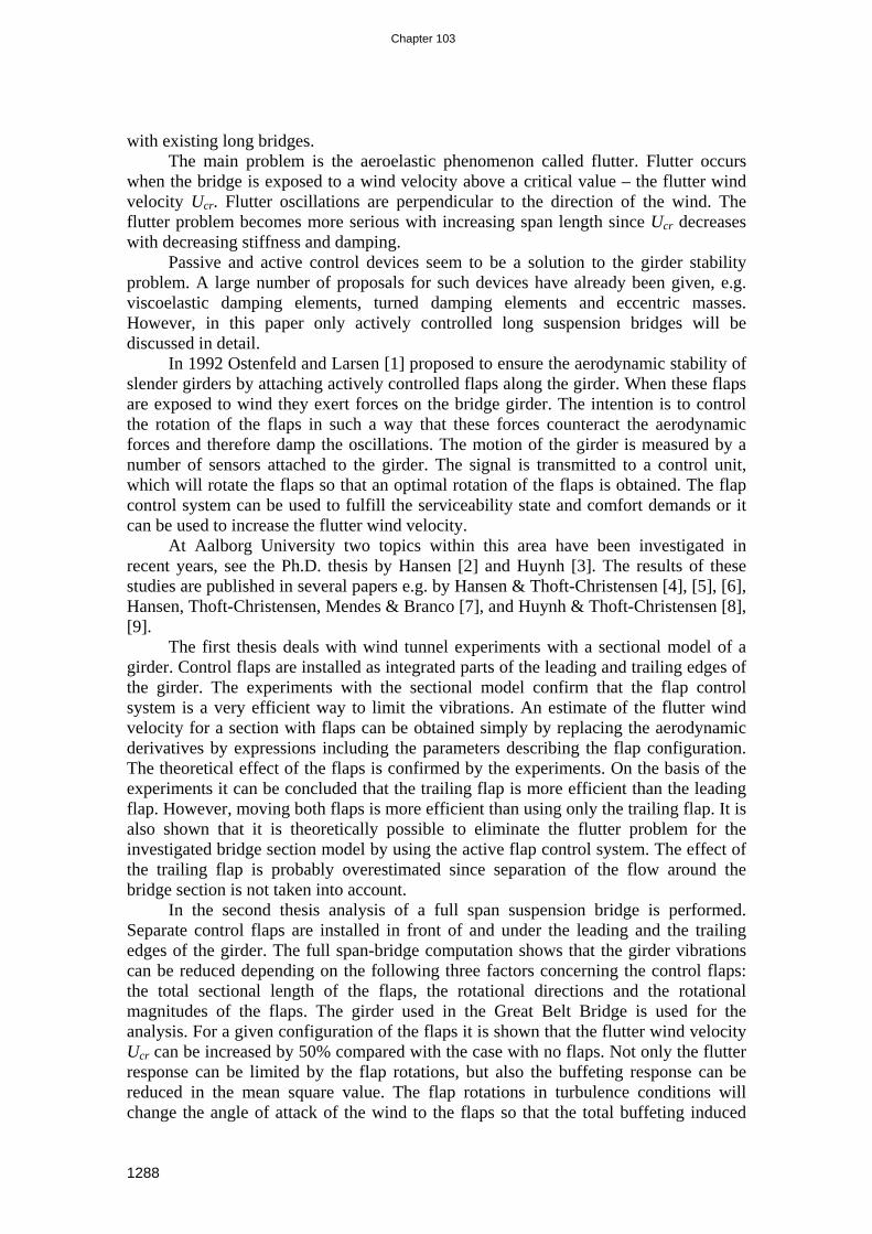
with existing long bridges. The main problem is the aeroelastic phenomenon called flutter. Flutter occurs
when the bridge is exposed to a wind velocity above a critical value – the flutter wind velocity Ucr. Flutter oscillations are perpendicular to the direction of the wind. The flutter problem becomes more serious with increasing span length since Ucr decreases with decreasing stiffness and damping.
Passive and active control devices seem to be a solution to the girder stability problem. A large number of proposals for such devices have already been given, e.g. viscoelastic damping elements, turned damping elements and eccentric masses. However, in this paper only actively controlled long suspension bridges will be discussed in detail.
In 1992 Ostenfeld and Larsen [1] proposed to ensure the aerodynamic stability of slender girders by attaching actively controlled flaps along the girder. When these flaps are exposed to wind they exert forces on the bridge girder. The intention is to control the rotation of the flaps in such a way that these forces counteract the aerodynamic forces and therefore damp the oscillations. The motion of the girder is measured by a number of sensors attached to the girder. The signal is transmitted to a control unit, which will rotate the flaps so that an optimal rotation of the flaps is obtained. The flap control system can be used to fulfill the serviceability state and comfort demands or it can be used to increase the flutter wind velocity.
At Aalborg University two topics within this area have been investigated in recent years, see the Ph.D. thesis by Hansen [2] and Huynh [3]. The results of these studies are published in several papers e.g. by Hansen & Thoft-Christensen [4], [5], [6], Hansen, Thoft-Christensen, Mendes & Branco [7], and Huynh & Thoft-Christensen [8], [9].
The first thesis deals with wind tunnel experiments with a sectional model of a girder. Control flaps are installed as integrated parts of the leading and trailing edges of the girder. The experiments with the sectional model confirm that the flap control system is a very efficient way to limit the vibrations. An estimate of the flutter wind velocity for a section with flaps can be obtained simply by replacing the aerodynamic derivatives by expressions including the parameters describing the flap configuration. The theoretical effect of the flaps is confirmed by the experiments. On the basis of the experiments it can be concluded that the trailing flap is more efficient than the leading flap. However, moving both flaps is more efficient than using only the trailing flap. It is also shown that it is theoretically possible to eliminate the flutter problem for the investigated bridge section model by using the active flap control system. The effect of the trailing flap is probably overestimated since separation of the flow around the bridge section is not taken into account.
In the second thesis analysis of a full span suspension bridge is performed. Separate control flaps are installed in front of and under the leading and the trailing edges of the girder. The full span-bridge computation shows that the girder vibrations can be reduced depending on the following three factors concerning the control flaps: the total sectional length of the flaps, the rotational directions and the rotational magnitudes of the flaps. The girder used in the Great Belt Bridge is used for the analysis. For a given configuration of the flaps it is shown that the flutter wind velocity Ucr can be increased by 50% compared with the case with no flaps. Not only the flutter response can be limited by the flap rotations, but also the buffeting response can be reduced in the mean square value. The flap rotations in turbulence conditions will change the angle of attack of the wind to the flaps so that the total buffeting induced
1288

Chapter 103
forces acting on the girder system are reduced. The stochastic buffeting responses can be derived by a conventional stochastic response analysis in modal coordinates, and in accordance with the wind load consisting of a stochastic buffeting term and an aeroelastic term.
Controlling the vibrations of civil engineering structures using active control systems has been used primarily to fulfill serviceability and comfort requirements. For such cases failure of the control system is not critical for the users of the structures or the structure itself. The situation is completely different with regard to controlling the safety of a long-span bridge using a control system. In such a case a passive control system is preferred. 2. WIND LOADS ON SUSPENSION BRIDGES The three most important vibrations of a suspension bridge girder are motion-induced vibrations, buffeting-induced vibrations and vortex-induced vibrations. The motion-induced wind loads (aeroelastic forces) depend directly on deformations and deformation velocities of the girder, and are the subject of this paper. The buffeting-induced wind loads are the fluctuating wind loads due to the turbulence of the wind.
For thin airfoils in incompressible flow assuming potential flow theory Theodorsen [10] has shown that the motion-induced vertical load Lae(x,t) and the motion-induced moment Mae(x,t) on the airfoil are linear in theoretical displacement and the torsional angle and their first and second derivatives. Scanlan and Tomko [11] introduced this formulation into the bridge area. Let x, y and z be coordinates in the direction of the bridge, across the bridge and in the vertical direction, and let t be the time. The aeroelastic forces Ldeck and Mdeck per unit span and for small rotations can then be written, see Similu & Scanlan [12]
+++= ∗∗∗∗
Bv
KHKrKHKUrB
KKHUv
KKHBU
txL zx
xzDeckae )()()()(
2),( 4
23
221
2 r (1)
+++= ∗∗∗∗
Bv
KAKrKAKUrB
KKAUv
KKABU
txM zx
xzDeckae )()()()(
2),( 4
23
221
22 r (2)
where K=Bω /U is the non-dimensional reduced frequency, B is the girder width, U is the mean wind velocity, ω is the bridge oscillating frequency in rad at the wind velocity U, and r is air density. )(KHi∗ and )(KAi∗ (i=1,2,3,4) are non-dimensional aerodynamic derivatives determined in a wind tunnel. The quantities rx, Uvz and
UrB x are non-dimensional, effective angles of attack. 3. BRIDGE GIRDERS WITH FLAPS Two types of actively controlled flaps are shown in figure 2: Flaps arranged on pylons below the streamlined bridge girder (the second thesis) and flaps integrated in the bridge girder so each flap is the streamlined part of the edge of the girder (the first thesis).
1289

Chapter 103
When the flaps are exposed to the wind they exert forces on the bridge girder. The directions and sizes of the forces can be controlled by regulating the flaps. By providing forces, which counteract the motion of the girder the oscillations are damped. A number of sensors are
placed inside the bridge girder to measure the position or motion of the girder. The measurements are transmitted to the control unit, e.g. a computer. The flaps are regulated based on a control algorithm that uses the measurements. In this way the flaps can be regulated continuously to counteract the motion of the girder. The active control system is shown in figure 3. As for the airfoils, the loads due to movement of a trailing flap on a thin airfoil in incompressible flow are linear at the angle of the trailing flap and the first and second derivatives. By assuming that the angle of a leading flap has no
effect on the circulation it can be shown that the loads due to movement of a leading flap on a thin airfoil are also linear at the angle of the leading flap and the first and second derivatives. The motion-induced wind loads due to movement of the flaps can therefore be described by additional derivatives.
Figure 4 shows the increase of flutter velocity for different combinations of the flap rotations. α is the rotation of the girder, αl and αt are the rotations of the leading and the trailing flaps, lϕ and tϕ are the phase angles between the leading flap, the trailing flap and the girder, respectively. The results show that the flutter wind velocity is increased when the phase angle for the leading flap lϕ is in the interval
]66.6;66.0[ ππ , otherwise the flutter wind velocity is reduced. The flutter wind velocity for binary flutter is calculated for different values of amplification factor at and tϕ for the trailing flap. The leading flap is not moved. The results show that the interval where
the flutter wind velocity is increased when the trailing flap is moved is dependent of the flap at. The flutter wind velocity is generally reduced when the phase angle of the trailing flap
tϕ is in the interval ]66;6[ ππ . For phase
angles outside this interval the flutter wind velocity is generally increased. The trailing flap is much more
Figure 2: Sections with flaps on pylons and integrated in the section.
Figure 3: Active Control System.
[ ]m/s crU
063
===
t
l
l
απϕαα
068
===
l
t
t
απϕαα68
63πϕπϕ
ααα
==
==
t
l
tl
α
Figure 4: The theoretical effect of flaps.
1290

Chapter 103
efficient than the leading flap. 4. WIND TUNNEL TESTS
Wind tunnel testing of a bridge section model has been performed in a wind tunnel at Instituto Superior Téchnico in Lisbon, Portugal. The model is shown in figure 5. The regulation system for moving the flaps consists of three parts: a servo system, regulation software to position the flaps, and control software to calculate the desired positions of the flaps. A servo system consists of a servo amplifier, a servomotor and a reduction gear. Two servo systems are used so that the flaps can be regulated
independently. The reduction gears and servomotors are fixed inside the bridge section model. Each reduction gear is connected to the flaps via cables. Each servomotor is connected to a servo amplifier, which is placed outside the model.
Figures 6 and 7 show the torsional movement of the model when the flaps are not regulated (configuration 0) and when they are regulated (configuration 2). The wind speed is 6.1 m/s. Note that the units on the x-axis are different in the two figures. The conclusion is that configuration 2 is very efficient for controlling the torsional motion of the model. During the first second the torsional motion is reduced from 2.7° to 1.1°, i.e. 62%.
Several configurations of the flaps have been tested. As seen in figure 8, the experimental damping ratio is smaller for flap configurations 0 and 1 than the theoretical damping ratio, but the shape of the curve is almost the
same. For flap configuration 2 the experimental damping ratio exceeds the theoretical one. For flap
configurations 1 and 2, the theoretical curves show that no binary flutter will occur.
Figure 5: Wind tunnel model.
Figure 6: Torsional motion for flap configuration 0 and wind speed 6.1 m/s.
Figure 7: Torsional motion for flap configuration 2 and wind speed 6.1 m/s.
1291

Chapter 103
Figure 8: Theoretical (solid lines) and experimental damping ratio for torsional motion with wind for flap configuration 0-4. The number at the end of a solid line denotes the actual flap configuration. 5. SUSPENSION BRIDGE WITH CONTROLLED SEPARATE FLAPS In this section the coupled-flutter vibration of basic vertical and torsional modes is considered for a bridge girder with separate flaps. The total motion-induced wind loads per unit span on the girder and the flaps are, see figure 9
),(),( lexz
lez
trxz
trz
Deckz
totalz rvLrvLLL ++= (3)
( )2
),(),(),(),( BrvLrvLrvMrvMMM lex
lez
trx
trz
lexz
lex
trxz
trx
Deckx
totalx −−+++= (4)
Figure 9: Motion-induced wind load on the girder and the flaps, Huynh [3]. where vz(x,t) and rx(x,t) are the vertical motion and the rotation of the girder at position x along the bridge girder at the time t, and where
B
v
U
~ 0 for small rx
−v
−v
y
DeckzL
DeckxM
z
−v B
C v
y
trzL
trxM
lexM
lezL
trxr
lexr
xr
xr ),( txrx
),( txvz
),( txvz
),( txvz
Configuration ta la 0 0 0 1 1.9 2.0 2 3.4 3.6 3 2.0 2.0 4 3.4 3.6
1292

Chapter 103
),( txrlex , ),( txrtr
x : Rotation of the leading and the trailing flap from horizontal position.
),( lexz
lez rvL , ),( tr
xztrz rvL : Lift-induced forces from the leading and the trailing flap
),( lexz
lex rvM , ),( tr
xztrx rvM : Moment-induced forces from the leading and the
trailing flap ),(),( 2 txrtxv x
B= :Vertical displacement of the flaps due to the girder rotation rx.
2),( Btrx
trz rvL , 2),( Ble
xlez rvL − : Moment-induced forces from the lift of the leading and
the trailing flap due to the vertical displacement v(x,t).
The motion-induced forces per unit span of the flaps similarly to Eq. (1) and (2) can be written in the form:
+
+
=
∗∗∗
trx
lex
trx
lex
ztrxz
trz
lexz
lez
rrKHK
rr
UBKHv
UKHKBU
rvLrvL )'('')'(
11)'(
2''
),(),(
765
2
r
+
∗
11
')'(' 8
zvB
KHK (6)
+
+
=
∗∗∗
trx
lex
trx
lex
ztrxz
trx
lexz
lex
rrKAK
rr
UBKAv
UKAKBU
rvMrvM )'('')'(
11)'(
2''
),(),(
765
22
r
+
∗
11
')'(' 8
zvB
KAK (7)
+
+
−=
− ∗∗∗
trx
lex
trx
lex
trx
trz
lex
lez
rrKHK
rr
UBKHv
UKHKBU
rvLrvL )'('')'(
11)'(
2''
),(),(
765
2
r
−+
∗
11
')'(' 8 v
BKHK
(8)
UBK ω''= is the reduced frequency of the flaps, 'B is the flap width. )'(KHi∗ and )'(KAi∗ (i = 5,6,7,8) are the flutter derivatives of the flaps, determined by Theodorsen circulation function, see [3], [12] and [14]. (Note that ∗
5H , ∗6H , ∗5A and
∗6A symbolize in some cases the flutter derivatives related to the lateral mode, which
are omitted here for the streamlined girder). Determination of Ucr and ωcr is based on the modal analysis. The vertical modal wind load Fz and the torsional modal wind load Fx of the girder and on the flaps are given by:
dxxrvLtFL
ixzDeckz
Deckz )( ),()(
0∫= φ dxxrvMtF
L
ixzDeckx
Deckx )( ),()(
0∫= ψ (8)
1293

Chapter 103
( )( )( )
∫
−−
+
+
=
−
+
+2
1 )(2 ),(),(
)( ),(),(
)(),(),(
)()(
)()(
)()(L
Lj
lex
lez
trx
trz
jlexz
lex
trxz
trx
ilexz
lez
trxz
trz
lexz
trxz
lex
trx
lez
trz
dx
xBrvLrvL
xrvMrvM
xrvLrvL
tFtF
tFtF
tFtF
ψ
ψ
φ
(9)
where L2−L1 is the length of the flaps attached along the girder. L is general length of the deck referred to the side spans and the main span. φi(x) and ψj(x) are the vertical and the torsional mode shape of the bridge in mode i and mode j, assumed to be coupled at flutter. The total modal wind loads are:
)()()()()()(
)()()()(
tFtFtFtFtFtF
tFtFtFtF
lexz
trxz
trx
lex
Deckx
totx
trz
lez
Deckz
totz
−+++=
++= (10)
The governing modal equations for the two-mode flutter conditions are ( ) )()()(2)( 2 tFtztztzM tot
zzzzz =++ ωzω (11)
( ) )()()(2)( 2 tFtttM totxx =++ αωαzωα ααα 12)
where z(t) and α(t) are the vertical and the torsional modal coordinate. ωz, zz and ωα and zα are the natural frequencies and the damping ratios of the vertical and torsional modes. Mz and Mx are the vertical and the torsional modal mass. At the coupled motion, the vertical and the torsional modal responses are both assumed to be proportional to
tie ω , when the critical wind velocity is acting on the bridge, i.e. z(t) = tiez ω0 and α(t) = tie ωα0 . When this is introduced in the above equations the following matrix equation can be derived
=
00/
αBzA (13)
where the system matrix A depends of the natural mode shapes and frequencies, the damping ratios, the derivatives and the wind velocity. This matrix equation has non-trivial solutions when
0)(Im)(Re)( =+= AAA DetiDetDet (14) resulting in the following two flutter conditions for a bridge with separate flaps, Huynh [3]:
Φ+
Ψ+
+−+−
ΨΦ+
Φ+
Ψ+=
ωωωz
ωz
ωω
ωωωωωω
ω
αα m
LJM
LMLMMLMLmJm
LJ
M
zz
z
z
1222
213434211431)DetRe(
3
3
224224
4
04341 2
2
22
2
22
2
2
2=+
Φ−
Ψ−−−−+
zzz
zzz mL
JM
ωω
ωωω
ωzz
ωω
ωω
ωω αα
ααα (15)
1294

Chapter 103
[ ]
Ψ−
Φ−−−+
−−+
ΨΦ+
Φ+
Ψ=
222
2
33
3
324222
24 31 2431112)DetIm(
ωz
ωωωz
ωωzz
ωω
ωωωωω
αα
αα J
Mm
L
LMLMMLMLJmm
LJM
zzz
zz
z
022122
2
2
2=++
Φ
−Ψ
−+zz
zzz m
LJM
ωωz
ωωz
ωωω
ωωω α
ααα (16)
where m is the girder mass per unit span. Φ, Ξ and Ψ are the modal integrals of the girder given by:
∫∫∫ =Ψ=Ξ=ΦLLL
dxxdxxxdxx0
21
011
0
21 )( and , )()( , )( ψψφφ (17)
and where L1 to L4 and M1 to M4 contain the modal integrals of the flaps Φf , Ξ f and Ψf, the sum of flutter derivatives referred to the girder and the flaps (see Huynh [3] for full expressions). Finally, note that the flutter mode can be a coupling of more than two modes. In that case, an additional mode gives an additional equation like (13) or (14). The determinant condition (16) still remains in two parts (Real and Imaginary) but the derivation of the solution is rather complicated analytically. Generally, the obtained critical wind velocity Ucr and the critical frequency ωcr will not be varied by more than 5%, if several similar mode shapes with close frequencies are taken into account in the flutter computation (Huynh, [3]). 6. EXAMPLE In this section the theory presented above is illustrated by an example taken from Huynh [3]. The suspension bridge shown in figure 10 is considered. It has a streamlined cross-section similar to the cross-section of the Great Belt Bridge. The cable sag is 265 m, the pylon top is 360 m, the girder depth is 4 m, and the girder cross-sectional area is 1.056 m2. Applying both FEM and analytical calculation the 1st symmetrical vertical and torsional modes (SV1 and ST1) are 0.404 rad/s and 1.276 rad/s, respectively.
Figure 10: Suspension bridge used in the example.
Using the flutter conditions similar to (15) and (16), where Deckztotz FF = and
Deckxtotx FF = , i.e. without flaps, the critical wind velocity is Ucr = 58.21 m/s and the corresponding critical frequency is ωcr = 0.853 rad/s. When using the flaps, the increase of Ucr obtained from the conditions (15) and (16) depends on the three factors of the flap: the lengths (i.e. modal integrals Φf , Ξ f and Ψf), the rotational direction (i.e.
m 1000 m 1000m 2500
1295

Chapter 103
the signs of lexr and trxr , which are defined positive clockwise) and the rotational magnitudes (in terms of amplification factor a multiplied by the girder rotation rx, e.g.
)()(),(),( xtatxratxr lexlelex ψα== ). The most effective configuration of the flaps against flutter is the configuration
Minus + Plus (CMP), where the leading flap rotates against the girder xlelex rar −= , and the trailing flap rotates with the girder xtrtrx rar = , see figure 11.
Figure 11: Flutter in CMP of full flaps along the girder (* ωcr exceeds the ST1 frequency)
Figure 11 shows the increase of Ucr and ωcr for increasing ale and atr. For xlex rr 5.1−= and xtrx rr 5.1= , Ucr increases from 58.2 to 89.6m/s, i.e. 54%. The critical
frequency ωcr increases to the ST1 frequency (the torsional divergent flutter). By increasing ale and atr up to −3 and 3, Ucr and ωcr can still be found, but ωcr exceeds the ST1 frequency indicating that the higher modes can be involved in the flutter. Therefore, the length of the flaps can be reduced to 46% of the main span length in the centre to obtain an increase of Ucr by 50%, and with ωcr = 1.250 rad/s. 7. CONTROL OF VIBRATIONS So far, no control algorithms are used, but only the flutter conditions are discussed taking into account the physical wind loads generated by the girder and flaps under wind action. In order to identify the optimal control forces for a given wind velocity, the Independent Model Space Control (IMSC) has been chosen (Meirovith [13]). The system equation (13) can be transferred into the state equation:
)()()( ttt flapBFAqq += (18) where the state vector q(t) contains the modal displacements in the upper half, and the modal velocities in the lower half. Thus, the dimension of vector q(t) is 2(n+m), namely n vertical and m torsional modes. B is a matrix with zeroes in the upper half and inverse mass matrix in the lower half. F flap(t) is the actual control force vector that could be expected by using the flaps. By the state equation (18), one can get in mode i
x r
+
rx
rtr = atr rx rle = −ale rx
y
z −
*
0,4 0,8 1,2 1,6
2 2,4 2,8 3,2 3,2
0,
1,2
− −1.5 −2 −2.5 −1 1.5 2 2.5 3
Lead. ale Trail. atr
ωcr [rad/s]
70 90
110 130 150 170 190 210
−1 −1.5 −2 −2. −3 1 1.5 2 2.5 3
Lead. ale Trail. atr
Ucr [m/s]
1296

Chapter 103
)()()()( )( ,1
,, ttttt iRiiiRiiR wPRwGW −−=−= i =1, 2,…, (n+m) (19)
which expresses the IMSC relation between the modal control forces WR,i(t) and the modal deformation wR,i(t). Gi(t) is the control gain matrix, Ri is the control weighting matrix and Pi(t) is the Riccati matrix. WR,i(t) can be converted back to the actual control force F flap(t) by
[ ] )()( ,~1
tt iRTRI
flap WVMF−
= (20)
where [ ] ~1−TRIV is the pseudo-inverse of T
RIV , which is the matrix of the left eigenvectors of sytem matrix A, but contains only the real and imaginary parts. To solve (19) and (20), Pi(t) must satisfy the Riccati equation in mode i. By choosing the diagonal Riccati matrix Pi(t), and by considering only two modes (i.e. Pi12 = Pi21 = 0), the problem is simplified considerably. As the result, the target mode of control (flutter mode) has the unchanged critical frequency, whereas the other mode (vertical) has a frequency 14% higher than the vertical natural frequency (Huynh [3]).
The numerical results of the time history of the control responses and the control forces (i.e. the state vector q(t) after the control is in effect) are shown in figures 12 to 15 with two step choices of the control weighting factor Ri in mode i. The reduced control weighting factor R means that more control forces are required. The state weighting matrix Q has been chosen as the identity matrix, i.e. the vertical and torsional modes are weighted equally. The time history shows the results at the main span centre after the control responses have been multiplied by the mode shape values at the mid-span for the vertical and the torsional modes. The maximum vertical response is approximately 0.8 m and the maximum torsional response is about 2 degrees at the centre main span. These magnitudes are damped down to zero after approximately two minutes (Huynh [3]).
Figure 12: Control of vertical response in the main span centre.
Figure 13: Actual control lift.
R1 = R2 = 1×10³
vz(t) [m]
R1 = R2 = 20×103
vz(t) [m]
flapzRF [ N ] flap
zRF [ N ]
R1 = R2 = 20×103
R1 = R2 = 1×10³
1297

Chapter 103
Figure 14: Control of torsional response in the main span centre.
Figure 15: Actual control moment. 8. COMPARISON OF THE ACTUAL CONTROL FORCES AND THE MODAL
FORCES GENERATED BY THE FLAPS There are several ways to achieve the above optimal forces by the flaps. The optimal force control depends on the flap lengths, configurations and rotational magnitudes. These factors are referred to as the control-weighting factor R used above. The generalised forces of the flaps (aeroelastic) can be computed on the basis of the obtained optimal responses, with the corresponding wind velocity, and can than be compared to the optimal control forces (algebraic). Results show that only 9% of the main span length in the centre part needs the flaps in the CMM(−1,−1) to obtain flap
zRF ,
and only 3.5% length of the flaps is needed in the CMP(−1,1) to obtain flapxRF . Thus,
the rest of the flaps (if 46% is installed) for each case needs to rotate with other configurations to reduce the control spillovers. However, depending on the actual oscillation of the bridge, one favorable configuration of the flaps is first chosen (among many possibilities), so the control spillover problem is minimised from the beginning, before the rest of the flaps give the extra contribution, see Huynh [3]. 9. CONCLUSION Sectional wind tunnel tests and full bridge computations have shown that the integrated and separate flaps are effective to increase the critical wind velocity of the bridge. By the use of 46% of the main span length with the separate flap in the centre, and by using the configuration Minus-Plus, the flutter velocity can be increased unlimited if the flaps rotate more than three times the girder rotation. However, problem with control spillovers needs more investigation, e.g. the computation of different flap
R1 = R2 = 20×103
R1 = R2 = 1×10³
)(tF flapxR [ Nm ] )(tF flap
xR [ Nm ]
R1 = R2 = 1×10³
rx(t) [deg] rx(t) [deg]
R1 = R2 = 20×103
1298

Chapter 103
configurations acting simultaneously. Further, experiments with full-span bridge with different lengths of the flaps should be performed. 10. REFERENCES [1] Ostenfeld, K.H. & A. Larsen: Bridge Engineering and Aerodynamics. In
Aerodynamics of Large Bridges (editor A. Larsen), Proc. First Int. Symp. Aerodynamics of Large Bridges, Copenhagen, Denmark, 1992.
[2] Hansen, H.I.: Active Vibration Control of Long Suspension Bridges. Ph.D. thesis, Aalborg University, Denmark, 1998.
[3] Huynh, T.: Suspension Bridge Aerodynamics and Active Vibration Control. Ph.D. thesis, Aalborg University, Denmark, 2000.
[4] Hansen, H.I. & P. Thoft-Christensen: Wind Tunnel testing of Active Control System for Bridges. Proc. IABSE congress, Copenhagen, Denmark, 1996, pp.775-780.
[5] Hansen, H.I. & P. Thoft-Christensen: Active Vibration Control of Long Bridges Using Flaps. Proc. Second World Conf. Struct. Control, Kyoto, Japan, 1998.
[6] Hansen, H.I. & P. Thoft-Christensen: Wind Tunnel Experiments with Active Control of Bridge Section Model. Report from IABSE Symp. On “Long-Span and high-rise Structures, Kobe, Japan, 1998, pp.199-204.
[7] Hansen, H.I., P. Thoft-Christensen, P.A. Mendes & F.A. Branco: Wind Tunnel Tests of a Bridge Model with Active Vibration Control. Submitted to Structural Engineering International, IABSE
[8] Huynh, T. & P. Thoft-Christensen: Suspension Bridge Flutter for Girders with Separate Control Flaps. Accepted for publication in Journal of Bridge Engineering, ASCE,2000.
[9] Huynh, T. & P. Thoft-Christensen: Buffeting Response of Suspension Bridge Girder with Separate Control Flaps. Second European Conference on Structural Control, Champs-sur-Marne, France, July 3-6, 2000
[10] Theodorsen, T: General Theory of Aerodynamic Instability and the Mechanism of Flutter. NACA Report No. 496, 1935.
[11] Scanlan, R.H. & J.J.Tomko: Airfoil and Bridge Deck Flutter Derivatives. J.Eng.Mech.Div.,ASCE 97, Proc. Paper 8601, 1971, pp. 1717-1737.
[12] Simiu E. & R.H. Scanlan. Wind Effects on Structures: Fundamentals and Applications to Design, Third Edition, John Wiley and Sons, 1996.
[13] Meirowitch,L. Dynamics and Control of Structures. John Wiley & Sons, 1990. [14] Dyrbye, C. & S. O. Hansen. Wind Load on Structures, John Wiley & Sons, 1997.
1299

Chapter 103
1300