Embed Size (px)
Citation preview

Aalborg Universitet
Impact of Picocells on the Capacity and Energy Efficiency of Mobile Networks
Saker, Louai; Micallef, Gilbert; Elayoubi, S. E.; Scheck, H. O.
Published in:Annales des Telecommunications
DOI (link to publication from Publisher):10.1007/s12243-012-0287-x
Publication date:2012
Document VersionPublisher's PDF, also known as Version of record
Link to publication from Aalborg University
Citation for published version (APA):Saker, L., Micallef, G., Elayoubi, S. E., & Scheck, H. O. (2012). Impact of Picocells on the Capacity and EnergyEfficiency of Mobile Networks. Annales des Telecommunications, 67(3-4), 133-146.https://doi.org/10.1007/s12243-012-0287-x
General rightsCopyright and moral rights for the publications made accessible in the public portal are retained by the authors and/or other copyright ownersand it is a condition of accessing publications that users recognise and abide by the legal requirements associated with these rights.
? Users may download and print one copy of any publication from the public portal for the purpose of private study or research. ? You may not further distribute the material or use it for any profit-making activity or commercial gain ? You may freely distribute the URL identifying the publication in the public portal ?
Take down policyIf you believe that this document breaches copyright please contact us at [email protected] providing details, and we will remove access tothe work immediately and investigate your claim.
Downloaded from vbn.aau.dk on: November 04, 2021
Impact of picocells on the capacity and energy efficiencyof mobile networks
L. Saker & G. Micallef & S. E. Elayoubi & H. O. Scheck
Received: 15 December 2010 /Accepted: 18 January 2012 /Published online: 25 February 2012# Institut Télécom and Springer-Verlag 2012
Abstract The deployment of small cells in mobile net-works has aroused a large interest in the last few years. Thispaper investigates the impact of picocell deployment on theperformance and power consumption of mobile networks.Since different network upgrades introduce different perfor-mance gains, comparing different configurations exclusive-ly on their overall power consumption can be rather biased.For this reason, a new key performance indicator, termed“energy efficiency”, is introduced and used throughout thisstudy, bringing together network performance and its overallpower consumption. In the first section of the study, atheoretical analysis for the Erlang-like capacity of a net-work, considering a uniform topology and traffic, is per-formed, using queuing theory analysis, namely processor-sharing queues. Results show that in all cases the deploy-ment of picocells improve the performance of the network,however the energy efficiency is noted to be dependent onthe deployment scenario considered. In the second part ofthe study, a more realistic scenario with non-uniform topol-ogy and traffic is considered, which is carried out through alarge-scale system level simulator. Results show that bydeploying picocells in areas experiencing high levels of
traffic, the energy efficiency of the network can be consid-erably improved.
Keywords Mobile networks . Picocells . Energy efficiency .
Capacity . Sleep mode
1 Introduction
Since its first release, 3G wireless technology has come along way forward. Each new release of 3GPP specificationshas introduced a number of new features that offer greateropportunities for both consumers and network operatorsalike. 3GPP Release 10 specifies LTE-A, which introducesseveral significant improvements over LTE Release 9 [1].Examples of these are: relays, carrier aggregation, and Het-erogeneous Networks (HetNets). This paper investigates aspecial aspect of HetNets, which is the deployment of pico-cells to offload parts of the traffic from the macro layer ofthe network. Note that, although small cell deployment is apart of the LTE-A standard, it is in no way entirely restrictedto LTE-A. In fact, there is a large interest from networkoperators to assess the impact of small cell deployment onthe performance of their HSPA networks, in an attempt todefine an optimal deployment strategy for the next couple ofyears.
A good amount of research has been dedicated to inter-ference management between the macro and pico layers [2].This has also been often integrated within the framework ofSelf Organizing Networks [3]. This work focuses on thecapacity gains and energy impactions that can be expectedfrom deploying picocells.
The energy efficiency of the radio access networks hasbecome a widely discussed and critical issue for futurewireless networks (especially HSPA+, 3G LTE and LTE-
L. Saker (*) : S. E. ElayoubiOrange Labs,Issy les Moulineaux,Paris, Francee-mail: [email protected]
G. MicallefAalborg University,Aalborg, Denmark
H. O. ScheckNokia Siemens Networks,Espoo, Finland
Ann. Telecommun. (2012) 67:133–146DOI 10.1007/s12243-012-0287-x

Advanced). Macro base station sites are the most energy-consuming nodes in the access network and are at the heartof every green radio scheme [4, 5]. For this reason, besidesthe achievable capacity gains, this investigation mainly fo-cuses at the power consumption of the resulting heteroge-neous network. The energy efficiency of the network ismeasured by dividing the traffic capacity with the powerconsumption, as recommended by [4]. This measure isconsidered as a KPI for the overall quality of the network.
The subject of picocell deployment is in this study cov-ered from both a theoretical and a practical point of view. Atfirst, we start by considering a uniform deployment within anetwork with homogeneous traffic. Using queuing theorytechniques, the Erlang-like capacity, i.e., the maximum traf-fic intensity that can be served by the network under a targetquality of service (QoS), is calculated. Following this, a realHSPA network topology and traffic distribution are consid-ered for deploying picocells in traffic hotspots. In bothcases, energy models for both macro and picocells are usedto calculate the power consumption of the network. Resultsshow that in some scenarios, picocells have the potential ofincreasing the energy efficiency of mobile networks. This ishowever dependent on the maturity of the equipment andthe evolution of the macro layer of the network.
Since the traffic carried by the network varies constantlyand considerably over time, a sleep mode feature for thedeployed picocells is investigated for both cases. By puttinga number of picocells in sleep mode, further energy savingsare observed.
2 Related work
An important set of works on green radio have been dedi-cated to the reduction of the transmitted power of basestation sites. The objective is to find the optimal transmis-sion power that ensures sufficient network coverage andcapacity (see for instance [6, 7]). The impact of reducingthe cell size on the energy performance of a High-SpeedDownlink Packet Access (HSDPA) has been investigated in[8]. A reduction of the cell size from R1 to R2<R1 has beenshown to increase the power consumption gain of the cel-lular network by a factor n0(R1/R2)
2. However, alone, theseschemes are not sufficient to reduce the power consumptionof wireless networks and a sleep mode is thus necessary forany optimal design of green base stations [9]. A similarstudy, based on a real network scenario, has shown that byimplementing sleep mode during hours with low networktraffic, a daily energy saving in the order of 30% is possible[10].
With regards to the deployment of small cells, particularattention has been dedicated to the energy savings of indooraccess points [11, 12], where sleep mode mechanisms have
been used. Out-of-band low consumption radio moduleshave been used to awaken femtocells when a call arrives.
For an outdoor environment, small cells, or technicallylow-power base stations, have been shown to improve theenergy efficiency [13]. In this study, the approach is basedon a link budget analysis, where the average throughputs,with and without small cells, are compared for different cellranges and deployment scenarios. Although the obtainedresults give an interesting insight about outdoor small celldeployment, the dynamic behavior of users and the impactthat this has on the user-perceived QoS has not beenaddressed.
In this paper, we introduce both link budget and flow-level queuing theory analyses. With the main objectivebeing to preserve the QoS of users, capacity, and energyefficiency figures that consider the traffic intensity and thenumber of active picocells are derived. A network widesleep mode is also applied, where during low-traffic situa-tions, some of the picocells are shut down. To note that thissleep mode is performed in a semi-static way, meaning thatit depends on the average traffic, on an hour-by-hour basis.Putting picocells in sleep mode has no impact whatsoeveron the coverage of the network, since these are deployed indense urban areas for boosting capacity. Within such areas,it is the macro layer of the network that ensures coverage.
The remainder of this paper is organized as follows. Webegin, in Section 3, by considering a uniform deployment ofpicocells and showing how to calculate capacity and energyefficiency. Section 4 extends the study to the case of a non-uniform network topology and illustrates the capacity andenergy gains in different scenarios. Section 5 eventuallyconcludes the paper.
3 Analysis of a uniform deployment of picocells
3.1 Throughput calculations
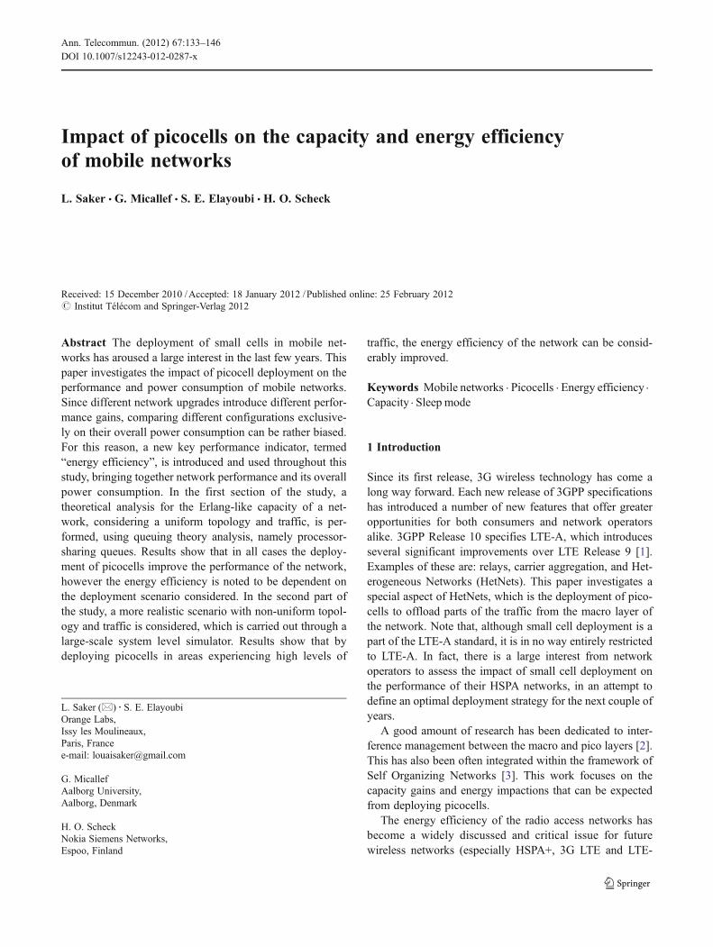
For the analytical calculations proposed in this paper, thedownlink of a uniform network configuration is considered.A user equipment (UE)M in the target cell 0 is characterizedby a distance R to base station 0 and an angle θ with areference axis as shown in the Fig. 1. The points at thecenter of all surrounding cells indicate the interferingevolved node Bs (eNBs). An omni-directional pattern an-tenna has been considered. The Okumura–Hata propagationmodel is used for macrocells. For pico-cells, the 3GPPmodel for outdoor relays is used. For each point of the cell,we derive the signal-to-interference-plus-noise-ratio (SINR)received from the target eNB and the different picocells. Theaim is to calculate the throughput of a UE located at thispoint and that is served by either the macrocell or thepicocell. Throughout these calculations, the interference
134 Ann. Telecommun. (2012) 67:133–146
generated from surrounding macrocells and picocells istaken into consideration.
For each node i (it being a picocell or macrocell) anaverage load in the interfering cells equal toc is assumed.Note that Table 1 contains the variables that are used in thissection and their meaning.
3.1.1 LTE
In LTE, χ is the average proportion of occupied resources inthe cell. The SINR can thus been calculated for each point ofthe cell as follows. For LTE, the same formula describes thedistribution of the number of collisions at each resourceblock (RB), be it allocated to a user served by an eNB or apicocell. Recall that an RB is the smallest amount of time-frequency resource that can be allocated to a user in LTE.
We define the vector X of zeros and ones whose dimensionis equal to the number of neighboring cells and whoseelements take the value 1 if there is a collision with thecorresponding cell. As for the macro networks studied in[14], the probability distribution of the number of collisionsis calculated by:
Pr X; cð Þ ¼ cXtX 1� cð Þ1�XtX
where Xt is the transpose of X. For a given vector ofcollisions X, the average SINR at each point of the cell,characterized by distance r to the macro eNB and angle θwith a reference axis (as shown in Fig. 1), can be calculatedfor the two different links. These are the direct link betweenthe eNB and the UE (SINReNB-UE), and the second linkbetween the picocell and the UE (SINRpico-UE):
SINR r; θ; cð Þ ¼XX
Pr X; cð Þ P0=q0 r; θð ÞPni¼1
XiPi
qi r;θð Þ þ N0
where Pmax is the maximum transmission power of the cell,q0 is the path loss between the receiver and the serving node,qi is the path loss between the receiver and the interferingnode, and N0 is the thermal noise.
3.1.2 HSDPA
In HSDPA, χ is the average proportion of cell power that isused for common and data channels. The interference
Fig. 1 Network configurationwith three picocells per site
Table 1 Variables used in this section and their meaning
Pmax Maximum transmission power of the cell
q0 Path loss between the receiver and the serving node
qi Path loss between the receiver and the interfering node
Pcom Power of common channels
α Orthogonality factor
S Spreading factor
F Interference factor
N0 Thermal noise
F Average file size
λ Overall arrival rate
Ann. Telecommun. (2012) 67:133–146 135

between cells is attenuated by the use of scrambling codes,in which case the SINR can be calculated by:
SINR r; θ; cð Þ ¼ S � Pmax
aPcom þ cPmaxF r; θð Þ þ N0q0 r; θð Þwhere Pcom is the power of common channels, α is theorthogonality factor, S is the spreading factor, and F is theinterference factor, as calculated in [15].
3.1.3 SINR
The UE will then be connected to the link offering the bestquality, leading to the final SINR equation:
SINR r; θ; cð Þ ¼ max SINReNB�UE r; θ; cð Þ;SINRpico�UE r; θ; cð Þ� �
Using the derived SINR values, link level curves can beused to obtain the throughput of an RB allocated to a UE inthe different points of the cell. An example of these curves isshown in Fig. 2. We obtain, by multiplying this throughputby the number of RBs available for each cell, Ktot,i (i0eNBor picocell), the peak throughput over all the areas coveredby node i, assuming that all the resources are allocated toone user.
Let Dc be this throughput, calculated at a given point, c,of the cell and N the number of points in the considered grid.
3.2 Flow-level capacity analysis
In the previous section, the achievable throughput at thedifferent positions within a cell, for a stand-alone user, hasbeen studied through link budget analysis. This is howevernot sufficient, since in high-traffic situations, several usersare scheduled in parallel. Thus, this requires a flow-level
capacity analysis, in which users arrive and depart from thecell dynamically.
A network carrying elastic traffic and which is composedof only macrocells can be modeled as a processor-sharingqueue, and its evolution described by the overall number of
users in the cell n ¼ PCc¼1 nc [16]. The cell load is calculat-
ed by ρ(λ)0λF/D, where F is the average file size, λ is theoverall arrival rate and,
D ¼XC
c¼1
lclDc
� ��1
is the harmonic mean of the throughput. The probability ofhaving n active users in the cell is given by:
pðnÞ ¼ ρn 1� ρð ÞIf a target throughput T is sought, it is possible to show
that the probability for users in position c, to achieve thisthroughput is given by:
QoSc lð Þ ¼Xkcm¼1
pðmÞ ¼ 1� kc þ 1ð Þρkc þ kcρkcþ1
where kc0Dc/T is the maximum number of allowed users inthe cell such that the throughput of a user in position c isacceptable. The average QoS over the cell is thus:
QoS lð Þ ¼XCc¼1
lclQoScðlÞ
When picocells are introduced, the cell site is modeled asa network of processor-sharing queues as shown in Fig. 3,where the traffic is divided and served by the availablenodes (macrocell or picocell). The traffic at each node isgiven by the proportion of cell locations whose best server isthat node. Let Spi and Sm be the area of surface covered bypicocells i (i01… k) and the macrocell. These areas arecalculated by the proportion of cell locations covered byeach node (macrocell or picocell). The arrival rate λpi of
picocell i is equal to lpi ¼ l SpiS whereas the arrival rate λm of
macro equals to lm ¼ l SmS with S the area of cell.
3.3 Power consumption of network nodes
Macro base stations Through empirical studies, the powerconsumption of a base station site is given as a function ofthe cell load for different configurations (number of sectors,installed baseband processing capacity), as shown in [5]:
Pmacro lð Þ ¼ Pp þ m PTRX þ ρ lð ÞPmax=cð Þwhere m is the number of installed sectors, Pp is the powerconsumption of the processing unit, PTRX is the fixed powerconsumption of the radio module, Pmax is the maximum
0 5 10 15 20 25 30 350
100
200
300
400
500
600
SINR (dB)
RB
dat
a ra
te (
kbps
)
Fig. 2 Downlink LTE link curve
136 Ann. Telecommun. (2012) 67:133–146
output power and c is the DC to RF conversion factor. Theload ρ is a function of the offered traffic, and is calculated asshown in the previous section. Note that, in multiple-inputand multiple-output (MIMO) 2×2 case, each sector willhave two transmission chains, so that m can be regarded asmultiplied by 2. Table 2 presents the set of values that areused to find the power consumption of a macro BTS:
Pico base stations In comparison to macro BTS, picocellsoperate at much lower transmission power (1 watt). Theenergy model above shows that the power consumption ofa BTS is only lightly correlated to the load. This means thatin a picocell that is transmitting little power, the variation inpower consumption with load will have an insignificantimpact on the overall consumption of the network. As aresult, picocells are assigned a fixed power consumption. Inorder to study the sensitivity of the results, the power con-sumption (Ppico) is varied from 10 to 70 W. Actual con-sumption figures of picocells are believed to be in the region
of 60–70 W; however, this is likely to decrease as theefficiency of the equipments is improved.
Considering the macro together with the K-deployed pico-cells, the power consumption of a network node is given by:
Pcell lð Þ ¼ Pmacro lð Þ þ K � Ppico
An additional term, energy efficiency, is introduced toput into perspective the power consumption of the networkwith the ability of the network to carry traffic. This isdefined as the ratio between the capacity of the networkand the power consumption, and is expressed in capacity perwatt per unit surface. Note that the term “capacity” has to beprecisely defined. From an operator point of view, the ca-pacity is the maximal amount of traffic that can be served bythe network, under a target QoS. This is expressed by:
C ¼ lmax; QoS lmaxð Þ ¼ QoStarget
Note that the energy efficiency is generally expressed bya volume of data per kilowatt hour (megabit per kilowatthour). However, since we calculate cell capacity in volumeper unit time (kilobits per second), the energy efficiency issimply the capacity divided by the power (1 Kbps/W0
3600×Mbit/KWh).
3.4 Sleep mode application
When dimensioning a mobile communications network, thebusy hour traffic is taken as a reference to calculate therequired network capacity and the number of base stationsites needed. However, such high volumes of traffic canonly be observed for about 2 to 3 h a day. For this reason,a sleep mode mechanism that shuts down capacity enhanc-ing sites when traffic is below a certain threshold can beused to improve the energy efficiency of the network. In thisstudy, sleep mode is only allowed for the deployedpicocells.
Assuming that the requested QoS is ensured, in the eventthat one or more picocells, within a particular macrocell, arenot utilized (too much network capacity for requested trafficvolume), then these picocells are shut down, reducing theoverall power consumption. If k picocells, among the Kexisting ones, are shut down, the power consumption isgiven by:
Pcell ¼ Pmacro þ K � kð ÞPpico
3.5 Results
In order to evaluate the impact of picocell deployment andsleep mode on the power consumption and QoS of thenetwork, some numerical results are hereby presented. An
Fig. 3 Queuing model (macrocell with k picocells)
Table 2 BTS modelparameters Pp 110 W
PTRX 100 W
Pmax 40 W
c 0.32
Ann. Telecommun. (2012) 67:133–146 137

LTE-A network in a dense urban area, with an inter-sitedistance of 800 m, is assumed. The transmission power forpicocells is set to 30 dBm (1 watt). These are deployed closeto the cell edge, at 450 m from the macro eNB.
In order to compare the impact that a different number ofpicocells have, four deployment strategies are considered:
& Macro only: no picocells are deployed.& Light-pico: deploying three picocells/sites (one picocell
per cell).& Medium-pico: deploying six picocells/sites (two pico-
cells per cell).& High-pico: deploying nine picocells/sites (three pico-
cells per cell).
In Fig. 4, we plot the cell outage rate, i.e., the probabilitythat the achievable user throughput is less than the target500 Kbps. For all four deployment scenarios, the traffic isincreased from 10 to 25Mbps/cell. The term outage rate canbe considered as being inversely proportional to the QoS.From this figure, if a target outage rate of 5% (or less) issought, the Erlang-like capacity can be derived (first line ofTable 3).
With regard to the power consumption shown in Fig. 5,as expected this is noted to increase when additional pico-cells are deployed in the network. From Figs. 4 and 5, wecan obtain the power consumption corresponding to themaximum capacity that the network can carry (second lineof Table 3). Note that, even if the power consumption of thenetwork increases, the deployment of picocells is necessaryand is driven by the need to boost network capacity in orderto accommodate the increase in traffic.
As previously mentioned, the energy efficiency is mea-sured in capacity per watt per unit surface. Since a constantinter-site distance for macrocells is considered, the energy
efficiency can be measured in kilobit per second per wattcell. Table 4 compares the energy efficiency for the fourpreviously described strategies for different values of Ppico.As expected, the energy efficiency is inversely propor-tional to the picocell power consumption. When com-pared to the macro-only case, a dense picocell deployment ismore energy efficient for Ppico less than 30 W. The table alsoshows that by having picocells with lower power consump-tion, the same energy efficiency can be achieved with fewerpicocells.
To investigate the impact on the performance of intro-ducing sleep mode in picocells, the traffic of a typical cellover a 24-h period (Fig. 6) is simulated. While in a typicalcell, the volume of traffic varies over time, with a peakobserved during the busy hour, traffic is noted to decreaseconsiderably during night time hours.
Figure 7 shows the number of picocells that are neededduring each hour of the day for ensuring the same targetQoS. This number is calculated as follows:
– For each traffic intensity (each hour of the day, denotedt), the QoS is analyzed following the above describedmodel, when there are x active picocells, with x03, 6,and 9. Let QoS(t, x) is the QoS when there are x activepicocells, at time t00,…, 23.
Table 3 Capacity and power consumption of different strategies withPpico030 W
Macroonly
3 picocells 6 picocells 9 picocells
Capacity(Mbps/cell)
15 16 17 19.5
Power (W/cell) 352.66 384.6 414.74 446.67
10 15 20 250
0.02
0.04
0.06
0.08
0.1
0.12
0.14
Traffic (Mbps)
Out
age
rate
Macro only
Light-picoMedium-pico
High-pico
Fig. 4 Cell outage rate (Ppico030 W)
10 15 20 25300
320
340
360
380
400
420
440
460
480
Traffic (Mbps)
Pow
er c
onsu
mpt
ion
per
cell
(W)
Macro only
Light-picoMedium-pico
High-pico
Fig. 5 Power consumption in the cell (Ppico030 W)
138 Ann. Telecommun. (2012) 67:133–146

– The optimal number of picocells, for each hour of theday, is then setup so that the minimal QoS is satisfied:
x tð Þ ¼ arg inQoS t; xð ÞSubject to : QoS t; xð Þ � QoStarget
It is observed that the maximum number (9) of picocells,are only required at the busy hours (from 5pm to 6pm hoursand from 2000 hours to midnight). However, in hours withmedium to low traffic three, six, or even at times zeropicocells are needed. Figure 8 shows the power consump-tion of the cell area coverage (picocell+macrocell) with andwithout sleep mode corresponding to the traffic profile inFig. 6. The average energy efficiencies obtained for the twoschemes are: 45 Kbps/W/cell for the case without sleepmode and 52 Kbps/W/cell for the case with sleep mode.This corresponds to an increase in energy efficiency of 16%.
4 Non-uniform traffic case
In reality, base station sites of actual mobile networks areorganized in an irregular (but yet planned) topology, withsites being individually positioned and oriented. The traffic
carried by each cell varies considerably over time, and for aspecific moment in time, the traffic within one cell is likelyto be different from that of a neighboring cell. Due to suchissues, a simple link budget analysis is not sufficient to fullyunderstand the implications that the deployment of picocellscould have within a real mobile network. Because of this, inaddition to the previously presented theoretical analysis,detailed network simulations based on a real HSPA networkhave also been carried out. In existing HSPA networks, thedeployment of picocells is not the only option for boostingcapacity. Other options include: the upgrade of existing sitesto HSPA+, the deployment of new macro sites (site densifi-cation), the installation of additional HSPA carriers, and theupgrade of selected sites to six sectors. For this reason, theimpact of picocells on the power consumption and efficiencyis also compared with a small selection of the above capacityenhancing options.
2 4 6 8 10 12 14 16 18 20 22 240
5
10
15
20
25
30
35
Time (hours)
Dat
a tr
affic
(M
bps)
Fig. 6 Average offered data traffic over the day
2 4 6 8 10 12 14 16 18 20 22 240
1
2
3
4
5
6
7
8
9
10
Time (hours)
Num
ber
of P
ico
cell
need
ed
Fig. 7 Number of needed picocells over the day
2 4 6 8 10 12 14 16 18 20 22 24300
320
340
360
380
400
420
440
460
480
Time (hours)
Pow
er c
onsu
mpt
ion
(W)
With SM
Without SM
Fig. 8 Power consumption over the day, for nine picocell sites, with,and without sleep mode
Table 4 Energy efficiency (kilobits per second per watt per cell) withdifferent values of Ppico
Ppico
10 W 20 W 30 W 40 W 50 W 60 W 70 W
Macro only 43.5 43.5 43.5 43.5 43.5 43.5 43.5
3 picocells 44 43 42 40.5 39.5 38.5 38
6 picocells 45.5 43.5 41 39.5 37.5 36 34.5
9 picocells 50.5 47 44 41 38.5 36.5 34.5
Ann. Telecommun. (2012) 67:133–146 139
4.1 Network simulator description
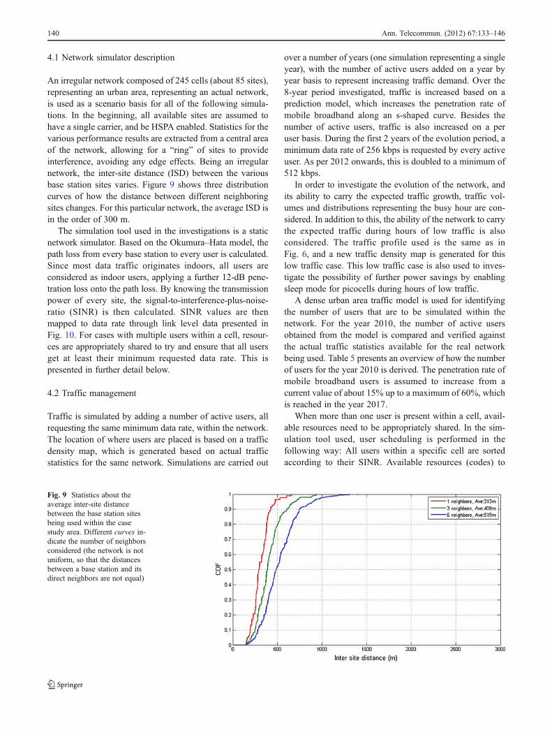
An irregular network composed of 245 cells (about 85 sites),representing an urban area, representing an actual network,is used as a scenario basis for all of the following simula-tions. In the beginning, all available sites are assumed tohave a single carrier, and be HSPA enabled. Statistics for thevarious performance results are extracted from a central areaof the network, allowing for a “ring” of sites to provideinterference, avoiding any edge effects. Being an irregularnetwork, the inter-site distance (ISD) between the variousbase station sites varies. Figure 9 shows three distributioncurves of how the distance between different neighboringsites changes. For this particular network, the average ISD isin the order of 300 m.
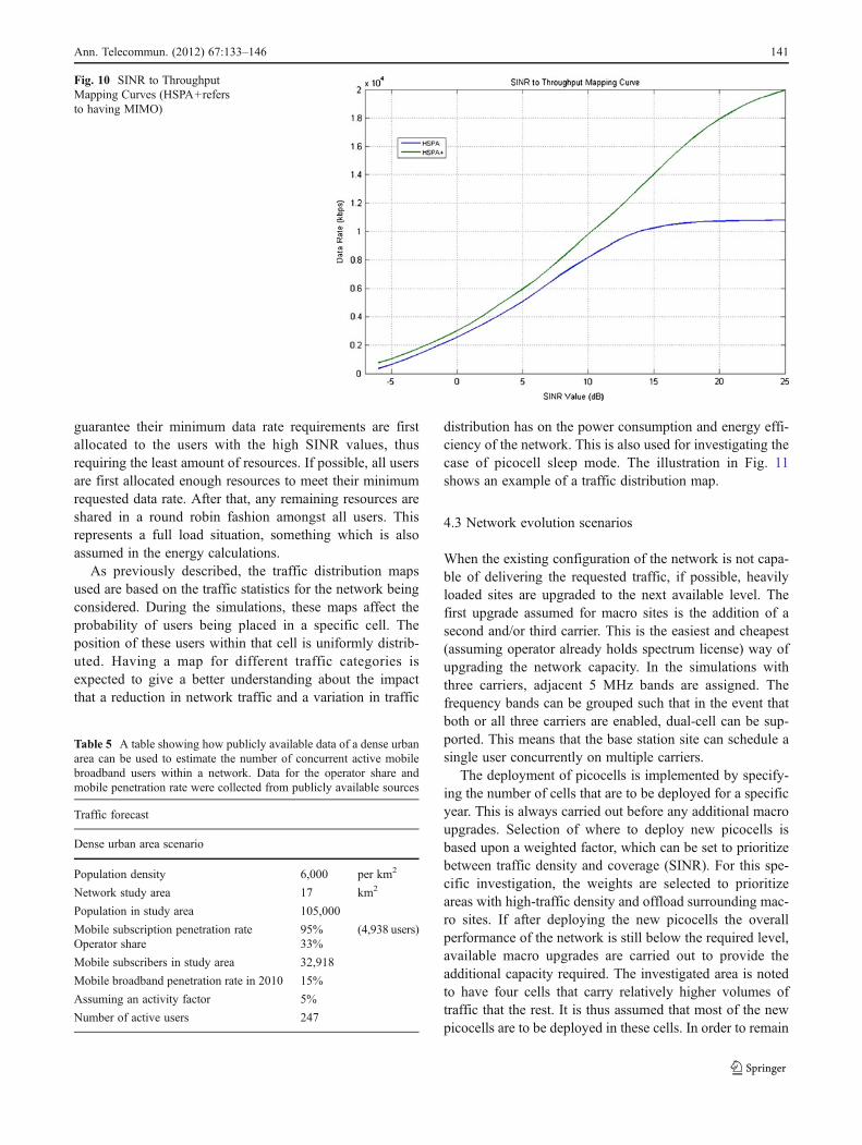
The simulation tool used in the investigations is a staticnetwork simulator. Based on the Okumura–Hata model, thepath loss from every base station to every user is calculated.Since most data traffic originates indoors, all users areconsidered as indoor users, applying a further 12-dB pene-tration loss onto the path loss. By knowing the transmissionpower of every site, the signal-to-interference-plus-noise-ratio (SINR) is then calculated. SINR values are thenmapped to data rate through link level data presented inFig. 10. For cases with multiple users within a cell, resour-ces are appropriately shared to try and ensure that all usersget at least their minimum requested data rate. This ispresented in further detail below.
4.2 Traffic management
Traffic is simulated by adding a number of active users, allrequesting the same minimum data rate, within the network.The location of where users are placed is based on a trafficdensity map, which is generated based on actual trafficstatistics for the same network. Simulations are carried out
over a number of years (one simulation representing a singleyear), with the number of active users added on a year byyear basis to represent increasing traffic demand. Over the8-year period investigated, traffic is increased based on aprediction model, which increases the penetration rate ofmobile broadband along an s-shaped curve. Besides thenumber of active users, traffic is also increased on a peruser basis. During the first 2 years of the evolution period, aminimum data rate of 256 kbps is requested by every activeuser. As per 2012 onwards, this is doubled to a minimum of512 kbps.
In order to investigate the evolution of the network, andits ability to carry the expected traffic growth, traffic vol-umes and distributions representing the busy hour are con-sidered. In addition to this, the ability of the network to carrythe expected traffic during hours of low traffic is alsoconsidered. The traffic profile used is the same as inFig. 6, and a new traffic density map is generated for thislow traffic case. This low traffic case is also used to inves-tigate the possibility of further power savings by enablingsleep mode for picocells during hours of low traffic.
A dense urban area traffic model is used for identifyingthe number of users that are to be simulated within thenetwork. For the year 2010, the number of active usersobtained from the model is compared and verified againstthe actual traffic statistics available for the real networkbeing used. Table 5 presents an overview of how the numberof users for the year 2010 is derived. The penetration rate ofmobile broadband users is assumed to increase from acurrent value of about 15% up to a maximum of 60%, whichis reached in the year 2017.
When more than one user is present within a cell, avail-able resources need to be appropriately shared. In the sim-ulation tool used, user scheduling is performed in thefollowing way: All users within a specific cell are sortedaccording to their SINR. Available resources (codes) to
Fig. 9 Statistics about theaverage inter-site distancebetween the base station sitesbeing used within the casestudy area. Different curves in-dicate the number of neighborsconsidered (the network is notuniform, so that the distancesbetween a base station and itsdirect neighbors are not equal)
140 Ann. Telecommun. (2012) 67:133–146
guarantee their minimum data rate requirements are firstallocated to the users with the high SINR values, thusrequiring the least amount of resources. If possible, all usersare first allocated enough resources to meet their minimumrequested data rate. After that, any remaining resources areshared in a round robin fashion amongst all users. Thisrepresents a full load situation, something which is alsoassumed in the energy calculations.
As previously described, the traffic distribution mapsused are based on the traffic statistics for the network beingconsidered. During the simulations, these maps affect theprobability of users being placed in a specific cell. Theposition of these users within that cell is uniformly distrib-uted. Having a map for different traffic categories isexpected to give a better understanding about the impactthat a reduction in network traffic and a variation in traffic
distribution has on the power consumption and energy effi-ciency of the network. This is also used for investigating thecase of picocell sleep mode. The illustration in Fig. 11shows an example of a traffic distribution map.
4.3 Network evolution scenarios
When the existing configuration of the network is not capa-ble of delivering the requested traffic, if possible, heavilyloaded sites are upgraded to the next available level. Thefirst upgrade assumed for macro sites is the addition of asecond and/or third carrier. This is the easiest and cheapest(assuming operator already holds spectrum license) way ofupgrading the network capacity. In the simulations withthree carriers, adjacent 5 MHz bands are assigned. Thefrequency bands can be grouped such that in the event thatboth or all three carriers are enabled, dual-cell can be sup-ported. This means that the base station site can schedule asingle user concurrently on multiple carriers.
The deployment of picocells is implemented by specify-ing the number of cells that are to be deployed for a specificyear. This is always carried out before any additional macroupgrades. Selection of where to deploy new picocells isbased upon a weighted factor, which can be set to prioritizebetween traffic density and coverage (SINR). For this spe-cific investigation, the weights are selected to prioritizeareas with high-traffic density and offload surrounding mac-ro sites. If after deploying the new picocells the overallperformance of the network is still below the required level,available macro upgrades are carried out to provide theadditional capacity required. The investigated area is notedto have four cells that carry relatively higher volumes oftraffic that the rest. It is thus assumed that most of the newpicocells are to be deployed in these cells. In order to remain
Fig. 10 SINR to ThroughputMapping Curves (HSPA+refersto having MIMO)
Table 5 A table showing how publicly available data of a dense urbanarea can be used to estimate the number of concurrent active mobilebroadband users within a network. Data for the operator share andmobile penetration rate were collected from publicly available sources
Traffic forecast
Dense urban area scenario
Population density 6,000 per km2
Network study area 17 km2
Population in study area 105,000
Mobile subscription penetration rate 95% (4,938 users)Operator share 33%
Mobile subscribers in study area 32,918
Mobile broadband penetration rate in 2010 15%
Assuming an activity factor 5%
Number of active users 247
Ann. Telecommun. (2012) 67:133–146 141

in line with the previous investigation a number of picocelldeployment scenarios are considered:
& Macro-only upgrades—no picocells deployed.& Light deployment of picocells (pico-low)—deploying
four picocells per evolution year.& Medium deployment of picocells (pico-medium)—
deploying eight picocells per evolution year.& Dense deployment of picocells (pico-high)—deploying
12 picocells per evolution year.
4.4 Simulation results
4.4.1 Performance of the network
The main parameter defining the performance of the networkis percentage of users that are in outage, i.e., that do not
achieve their minimum requested data rate. The requestedtarget value is 5%, which has a tolerance band around to allowfor the various algorithms to converge. These tolerance bandsare marked in Fig. 12 with dotted red lines, with the upperbound (7%) being the one to stay below. The fluctuationswithin this and other similar figures come as a result of variouscapacity boosts introduced by the various upgrades.
When comparing the different scenarios being consid-ered, it is noticed that the available macro upgrades alone,are not sufficient to sustain the growth in traffic. This isnoted in the years 2016 and 2017 when the percentage ofusers in outage goes up to 7.4% and 9.8%., respectively. Onthe other hand, the introduction of picocells is noted toensure that the percentage of users in outage remains belowthe required threshold.
With regards to the average achievable data rate per user, itis noted that on average, this is about four times higher thanthe minimum requested data rate. Since the evolution andupgrade of the network are carried out following the samerequirements, it is noted that different options give similarperformance results when considering average user data rates.
4.4.2 Upgrade of the network
The introduction of picocells is expected to off-load neighbor-ing macro sites, reducing the extent or need for their upgrade.Figure 13 shows the extent of required upgrades in the net-work for the four different cases in the year 2017. It is clearthat the more picocells are deployed, the less macro siteupgrades are required. Already by deploying a few picocells,the need for deployingMIMO is avoided. Additional picocellsalso eliminated the need to use a third carrier.
4.4.3 Network power consumption
By assuming the same energy models previously used, ittakes about 26 picocells (at 70 W per picocell) to consume
Fig. 11 A traffic distribution map. The cell coverage area for each siteis assigned through simulations based only on the pilot power. This isused to determine the SINR in all pixels and assigning a serving basestation for any users in that pixel. Cell serving areas are depicted by acolor map
Fig. 12 Network performancein terms of percentage of usersin outage, highlighting thetarget acceptable areas
142 Ann. Telecommun. (2012) 67:133–146

the same power that a three-carrier site with MIMO would.This clearly indicates that reducing the number of macroupgrades should reduce the overall power consumption ofthe network. Results show (Fig. 14) that the power con-sumption of the macro-only case and that of the pico-lowand pico-medium are comparable only up until 2014. Fol-lowing that, the introduction of MIMO, boosts up the powerconsumption. This leaves all pico cases consuming lesspower. For all pico cases, the first 2 years, show a slightincrease in power consumption when compared to macro-only case. This occurs since in the macro-only case noupgrades are carried out in these years.
From 2012 onwards, the pico-high case is noted to have amore positive impact on the overall power consumption ofthe network, showing a reduction of 30% in comparison tothe macro-only case (for the year 2017). The pico-low andpico-medium cases perform similarly showing a reduction
in power consumption during 2017 of about 25%. If con-sidered over a 5-year period, when most of the macroupgrades are carried out the reduction in power consump-tion is averaged to 17% for the pico-high case, and 10% forthe other two pico cases.
4.4.4 Network energy efficiency
In order to bring together the performance of the networktogether with the power consumption, this investigation alsoconsiders the energy efficiency of the network. This ismeasured in kilobits per second per watt and measures thetraffic that the network (kilobits per second) can carry perunit of power (watt). Results, presented in the Fig. 15 showthat throughout the evolution period, the energy efficiencyof the network increases from an average of 8 Kbps/W up toan average of about 25 Kbps/W, irrespective of what
Fig. 13 This figure shows thestate of the network at the year2017. The different columnsshow the extent to which thesites are upgraded
Fig. 14 This figure shows thepower consumption of thenetwork over the evolutionperiod. The reference used isthe power consumption of themacro-only network of the year2010
Ann. Telecommun. (2012) 67:133–146 143

upgrade is used. This overall increase in efficiency comesfrom the fact that necessary network upgrades are carriedout in the areas with high traffic, so the increase in capacityovercomes the increase in power consumption. While over-all, the differences between the various cases are not sodrastic, by comparison it is noted that the macro-only up-grade performs worse throughout the evolution. The pico-medium and pico-high, which are the cases performing bestwith similar energy efficiency figures, give an average gainin energy efficiency of 15.5%.
4.4.5 Picocell power consumption sensitivity
In order to investigate the sensitivity of the above resultswith the power consumption value being used for picocells(70 W), different values are also considered (50 and 100 W).As noted in the previous section, an increase in power
consumption for picocells brings a reduction in the achiev-able power consumption gains. Nonetheless, when com-pared to the macro-only case, which is evolved by anumber of macro upgrades, it becomes clear that the de-ployment of picocells is more power effective, even in thecase when a massive 200 W per picocell is assumed. It isestimated that for that number of picocells, each wouldrequire to consume about 325 W for it to completely cancelthe gain in power consumption (Fig. 16).
4.4.6 Picocell sleep mode
Since traffic distribution of a mobile network varies contin-uously, during hours of low traffic, picocells deployed tohelp the macro layer during busy hours could now fall inareas with little or no traffic. For this reason, the impact ofthis shift in traffic distribution has been investigated on the
Fig. 15 The energy efficiencyof the network in kilobits persecond per watt throughout theevolution of the network for thedifferent upgrade options
Fig. 16 Sensitivity analysisshowing the impact on thepower consumption gain fordifferent pico powerconsumption values
144 Ann. Telecommun. (2012) 67:133–146
performance and energy efficiency in low traffic cases. Inaddition to this, since the network is noted to easily copewith low traffic conditions, the sleep mode mechanismpreviously presented was also implemented. In this casehowever, since hours corresponding to the lowest trafficare considered, all picocells are put into sleep mode. Notethat even if all picocells are shut down, the configuration ofthe network for the three pico deployment strategies isdifferent, as the macro sites are upgraded differently, asshown in Fig. 13.
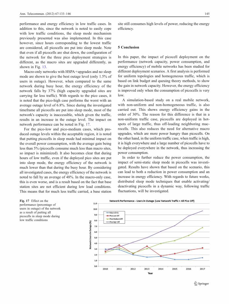
Macro-only networks with HSPA+upgrades and no sleepmode are shown to give the best outage level (only 1.5% ofusers in outage). However, when compared to the samenetwork during busy hour, the energy efficiency of thenetwork falls by 37% (high capacity upgraded sites arecarrying far less traffic). With regards to the pico cases, itis noted that the pico-high case performs the worst with anaverage outage level of 6.8%. Since during the investigatedtimeframe all picocells are put into sleep mode, most of thenetwork's capacity is inaccessible, which given the traffic,results in an increase in the outage level. The impact onnetwork performance can be noted in Fig. 17.
For the pico-low and pico-medium cases, which pro-duced outage levels within the acceptable region, it is notedthat putting picocells in sleep mode had minimal impact onthe overall power consumption, with the average gain beingless than 5% (picocells consume much less than macro sites,so impact is minimized). It also becomes clear that duringhours of low traffic, even if the deployed pico sites are putinto sleep mode, the energy efficiency of the network ismuch lower than that during the busy hour. By consideringall investigated cases, the energy efficiency of the network isnoted to fall by an average of 48%. In the macro-only case,this is even worse, and is a result based on the fact that basestation sites are not efficient during low load conditions.This means that for much less traffic carried, a base station
site still consumes high levels of power, reducing the energyefficiency.
5 Conclusion
In this paper, the impact of picocell deployment on theperformance (network capacity, power consumption, andenergy efficiency) of mobile networks has been studied fordifferent deployment scenarios. A first analysis is performedfor uniform topologies and homogeneous traffic, which isbased on link budget and queuing theory methods, to showthe gain in network capacity. However, the energy efficiencyis improved only when the consumption of picocells is verylow.
A simulation-based study on a real mobile network,with non-uniform and non-homogeneous traffic, is alsocarried out. This shows energy efficiency gains in theorder of 30%. The reason for this difference is that in anon-uniform traffic case, picocells are deployed in hot-spots of large traffic, thus off-loading neighboring mac-rocells. This also reduces the need for alternative macroupgrades, which are more power hungry than picocells. Onthe other hand, in the uniform traffic case, when traffic is high,it is high everywhere and a large number of picocells have tobe deployed everywhere in the network, thus increasing thepower consumption.
In order to further reduce the power consumption, theimpact of semi-static sleep mode in picocells was investi-gated. Results have shown that based on the scenario, thiscan lead to both a reduction in power consumption and anincrease in energy efficiency. With regards to future works,distributed sleep mode techniques that enable activating/deactivating picocells in a dynamic way, following trafficfluctuations, will be investigated.
Fig. 17 Effect on theperformance (percentage ofusers in outage) of the networkas a result of putting allpicocells in sleep mode duringlow traffic conditions
Ann. Telecommun. (2012) 67:133–146 145

References
1. 3GPP TS 25.306 V9.2.0, “Physical layer procedures (FDD)”, release 92. Viswanathan H, Stolyar AL (2010) Interference management in
femto/small cell and macro environments. IEEE CTW3. Stolyar AL, Viswanathan H (2009) Self-organizing dynamic frac-
tional frequency reuse for best effort traffic through distributed inter-cell coordination. INFOCOM’2009, Rio-de-Janeiro, April 19–25
4. ETSI TS 102 706 (2009) Energy efficiency of wireless accessnetwork equipment
5. Rinaldi R, Veca GM (2007) The hydrogen for base stations. In Proc.of Telecoms. Energy Conference, INTELEC’07, pp. 288–292
6. Kelif J, Coupechoux M, Marache F (2010) Limiting power trans-mission of green cellular networks: impact on coverage and ca-pacity, IEEE ICC
7. Palicot J (2009) Cognitive radio: an enabling technology for thegreen radio communications concept, IWCMC, June
8. Badic B, O'Farrell T, Loskot P, He J (2009) Energy efficient radioaccess architectures for green radio: large versus small cell sizedeployment. IEEE VTC-fall
9. Saker S, Elayoubi E, Chahed T (2010) Minimizing energy con-sumption via sleep mode in green base stations, IEEE WCNC-2010 Sydney
10. Micallef G, Mogensen P, Scheck HO (2010) Cell breathing andpossibilities to introduce cell sleep mode. European Wireless 2010
11. Haratcherev I, Fiorito M, Balageas C (2009) Low-power sleepmode and out of-band wake-up for indoor Access Points, IEEEGreenComm09
12. Claussen H, Ashraf I, Ho LTW (2010) Dynamic idle mode proce-dures for femtocells. Bell Labs Tech J 15(2):95–116
13. Richter F, Fehske AJ, Fettweis GP (2009) Energy efficiencyaspects of base station deployment strategies in cellular networks.In Proceedings of the 70th Vehicular Technology Conference(VTC Fall)
14. Elayoubi SE, Haddada OB, Fourestié B (2008) Performance eval-uation of frequency planning schemes in OFDMA-based networks.IEEE Trans. on Wireless Communications, vol.7, no.5
15. Baroudy A, Elayoubi SE (2007) HSUPA/HSDPA systems: capac-ity and dimensioning. IEEE FGCN 2007
16. Bonald T, Proutière A (2003) Wireless downlink data channels:user performance and cell dimensioning. ACM Mobicom
146 Ann. Telecommun. (2012) 67:133–146