Embed Size (px)
Citation preview

Aalborg Universitet
Hierarchical Control of Parallel AC-DC Converter Interfaces for Hybrid Microgrids
Lu, Xiaonan; Guerrero, Josep M.; Sun, Kai; Quintero, Juan Carlos Vasquez; Teodorescu,Remus; Huang, LipeiPublished in:I E E E Transactions on Smart Grid
DOI (link to publication from Publisher):10.1109/TSG.2013.2272327
Publication date:2014
Document VersionEarly version, also known as pre-print
Link to publication from Aalborg University
Citation for published version (APA):Lu, X., Guerrero, J. M., Sun, K., Vasquez, J. C., Teodorescu, R., & Huang, L. (2014). Hierarchical Control ofParallel AC-DC Converter Interfaces for Hybrid Microgrids. I E E E Transactions on Smart Grid, 5(2), 683 - 692.DOI: 10.1109/TSG.2013.2272327
General rightsCopyright and moral rights for the publications made accessible in the public portal are retained by the authors and/or other copyright ownersand it is a condition of accessing publications that users recognise and abide by the legal requirements associated with these rights.
? Users may download and print one copy of any publication from the public portal for the purpose of private study or research. ? You may not further distribute the material or use it for any profit-making activity or commercial gain ? You may freely distribute the URL identifying the publication in the public portal ?
Take down policyIf you believe that this document breaches copyright please contact us at [email protected] providing details, and we will remove access tothe work immediately and investigate your claim.
Downloaded from vbn.aau.dk on: maj 07, 2018

1
Abstract-- In this paper, a hierarchical control system for
parallel power electronics interfaces between ac bus and dc bus in
a hybrid microgrid is presented. Both standalone and grid-
connected operation modes in the dc side of the microgrid are
analyzed. Concretely, a three-level hierarchical control system is
implemented. In the primary control level, the decentralized
control is realized by using the droop method. Local ac current
proportional-resonant controller and dc voltage proportional-
integral controller are employed. When the local load is connected
to the dc bus, dc droop control is applied to obtain equal or
proportional dc load current sharing. The common secondary
control level is designed to eliminate the dc bus voltage deviation
produced by the droop control, with dc bus voltage in the hybrid
microgrid boosted to an acceptable range. After guaranteeing the
performance of the dc side standalone operation by means of the
primary and secondary control levels, the tertiary control level is
thereafter employed to perform the connection to an external dc
system. Meanwhile, the impact of the bandwidth of the secondary
and tertiary control levels is discussed. The closed-loop model
including all the three control levels is developed in order to
adjust the main control parameters and study the system stability.
Experimental results of a 2×2.2 kW parallel ac-dc converter
system have shown satisfactory realization of the designed system.
Index Terms - Hierarchical control, hybrid microgrid, parallel
power electronics converter interface
I. INTRODUCTION
owadays renewable energy generation is expected to be
highly penetrated into modern electric grids [1-2]. In
order to integrate different kinds of renewable energy sources,
the concept of microgrid was proposed several years ago [3].
Meanwhile, power electronics converters are usually used as
the interfaces to connect each source to the common bus in a
microgrid [4-6]. At the same time, ac and dc sources
sometimes coexist in a practical microgrid. In order to deal
with that, ac-dc hybrid microgrids have been studied in the
literature [7-8]. It is necessary to find effective control systems
This work was supported by the National Natural Science Foundation of
China (51177083) and China Scholarship Council.
X. Lu, K. Sun and L. Huang are with the State Key Lab of Power Systems,
Department of Electrical Engineering, Tsinghua University, Beijing, 100084,
China.
J. M. Guerrero, J. C. Vasquez and R. Teodorescu are with the Institute of
Energy Technology, Aalborg University, 9220, Denmark.
K. Sun is the corresponding author. Postal address: 3-310, West Main
Building, Tsinghua University, Beijing, China. Telephone number: 86-10-
62796934. Email: [email protected].
to facilitate the proper interaction between ac and dc buses in
hybrid microgrids.
Since the distributed renewable energy sources can be
connected into a microgrid separately, the interfacing
converters are usually connected in parallel. With the parallel
configuration, the load power sharing among the converters
has been a key research topic [9-13]. The output power should
be appropriately shared based on the power ratings of each
converter. Various power sharing methods have been proposed
and analyzed. Centralized control method is proposed in [14],
where a central controller is adopted to give the current
reference to each converter. Master-slave control in [15]
performs a combination of one voltage-controlled converter
and several current-controlled converters. The voltage-
controlled converter generates the current reference for the
other current-controlled converters. In [16], a method named
circular-chain-control (3C) is proposed, where the converters
are cascade connected and each converter generates the
current reference for the adjacent one. Average current control
method is shown in [17]. With the method, the current
references are generated and transferred to each converter
through a communication line. By using the above methods,
although the steady and dynamic performance of current
sharing can be guaranteed, the stability of the control system
highly depends on high speed communications. The system
redundancy is lowered down and the maintenance cost is
higher. Meanwhile, considering the distributed configuration
of a microgrid, the decentralized control method or the control
method based on low bandwidth communication (LBC) is
more suitable for microgrid applications. Therefore, the droop
control method has been commonly employed to perform
proper current sharing in a microgrid [10-13]. With droop
control, decentralized control for each interfacing converter is
achieved. At the same time, no communication or only LBC is
needed.
Among different communication methods, the local area
network (LAN)/Ethernet and the optical fiber transmission can
be used for the implementation of high bandwidth
communication (HBC). However, additional cost is needed to
achieve the infrastructure for this communication method [18-
19]. Controller area network (CAN) can be used as the LBC
method [20]. Particularly, when the transmission distance
becomes longer, the communication speed of CAN becomes
lower. Meanwhile, for LBC method, in ac systems, power line
communication (PLC) can be used [21], and PLC in dc
Hierarchical Control of Parallel AC-DC
Converter Interfaces for Hybrid Microgrids Xiaonan Lu, Student Member, IEEE, Josep M. Guerrero, Senior Member, IEEE, Kai Sun, Member,
IEEE, Juan C. Vasquez, Member, IEEE, Remus Teodorescu, Fellow, IEEE, Lipei Huang
N

2
systems has been also developed [22].
As ac power system is mainly utilized nowadays, more
attention is on ac microgrid [23-24]. However, many kinds of
renewable energy sources have dc output, such as photovoltaic
(PV) modules and batteries. As aforementioned, both dc and
ac components usually coexist in one system. Therefore, they
can form a hybrid microgrid. Different control methods of
hybrid microgrids have been proposed in the literature. Droop
control is employed in [7] and the controllable loads with
different capacities are taken into account. A coordinate
control method for a hybrid microgrid composed of various
kinds of renewable energy sources is proposed in [8], where
detailed models of PV modules, batteries and wind turbines
are derived and the energy management strategy for the whole
system is developed. A configuration with both dc and ac links
and the corresponding control method are presented in [25],
where the dc-link is employed to integrate the local converters
with dc couplings and it is connected to the common ac-link
through dc-ac interfacing converters. A power quality
enhancement method is proposed in [26], where the
unbalanced and nonlinear loads are taken into account and the
control strategy is developed in a multi-bus microgrid. The
above methods are useful to enhance the performance of a
hybrid microgrid. However, they mainly focus on the ac side
of the system. A typical ac-dc hybrid microgrid consists of
three main parts: (I) ac microgrid, (II) dc microgrid and (III)
power electronics interfaces between ac and dc buses. In [27],
a generalized droop control method is proposed to achieve the
proper power sharing in different parts of a hybrid microgrid,
while the deviation produced by droop control should be
further eliminated and the control of the power exchange
between the local and external grids should be discussed. In
[28], the control systems of ac microgrids and dc microgrids
are analyzed and a hierarchical control system is developed.
However, in the work related to the dc microgrids, only the
basic simulation results based on parallel buck converters are
shown. Meanwhile, the operation of the interfacing converters
between ac and dc buses is not included.
This paper accomplishes an extension of the hierarchical
control system with the discussion of different operation
modes, especially for the interfacing converters between ac
and dc buses in a hybrid microgrid. Meanwhile, the impact of
the LBC on the system stability is studied in detail. Concretely,
the hierarchical control system for the interfacing power
electronics converters consists of three levels. In the primary
level, distributed control is realized. Current proportional-
resonant (PR) controller and voltage proportional-integral (PI)
controller are achieved individually in each of the converters.
Droop controller for dc current sharing is also employed. In
the secondary control level, the dc voltage deviation produced
by droop control is eliminated. In order to realize current
sharing between parallel droop-controlled converters, there is
a tradeoff between current sharing accuracy and dc voltage
deviation [29]. The target of the secondary PI controller is to
restore the voltage deviation and maintain the current sharing
accuracy. Both the primary and secondary levels of the
hierarchical control system are employed in the dc-side
standalone operation mode. In order to control the power
exchange between local dc bus and other external dc grids, the
PI controller in the tertiary control level is used. It should be
noticed that both secondary and tertiary control levels have
remarkable low bandwidth characteristics, which guarantee
that the bandwidth will not interfere with the decentralized
controllers in the primary control level for each converter. The
performance of the control system with different
communication bandwidth is validated by experiment in detail
in this paper.
II. CLASSIFICATION OF DIFFERENT OPERATION MODES IN A
HYBRID AC-DC MICROGRID
As aforementioned, an ac-dc hybrid microgrid consists of
three parts: ac microgrid, dc microgrid and multiple parallel
interfaces between ac and dc buses. Considering the
configuration of the ac-dc hybrid system, different operation
modes and their power flow patterns are shown in Fig. 1.
Mode (a) and (b) are the operation modes of pure ac
microgrid and dc microgrid, respectively. Mode (c) and (d) are
the operation modes considering the interfacing converters
between ac and dc buses. In Mode (a), the ac loads are
supplied by the sources in the ac side. Meanwhile, when the ac
grid-connected static switch turns on, the power in the local
microgrid exchanges with the external ac grid. In Mode (b),
the local dc loads are supplied by the sources in the dc side.
When the dc grid-connected static switch turns on, the power
in the local microgrid exchanges with the external dc grid. In
Mode (c), the ac loads are supplied by the sources in the dc
side. When the system turns to grid-connected mode, the
power exchanges between the dc-side sources and external ac
grid. In Mode (d), the dc loads are supplied by the sources in
the ac side. When turning into grid-connected mode, the power
exchanges between the ac-side sources and external dc grid.
Notice that the practical operation modes can be regarded as
the composition of the above four basic operation modes.
Hierarchical control systems of Mode (a) and (b) have
already been discussed in [28]. In Mode (c), the dc bus voltage
is kept stable by controlling the converters in the dc microgrid.
This is out of scope of this paper since it is essentially from dc
to ac and the control system is equivalent to Mode (a). The
different operation modes and the usage of the hierarchical
control system in a hybrid microgrid are summarized in Table
I.
DC/AC
AC Loads
DC/DC
DC/DC
DC Loads
Part I
AC Microgrid
Part III
Interfaces between
AC and DC Buses
Part II
DC Microgrid
DC/AC AC/DC
AC/DC
External
AC GridExternal
DC Grid
Power Switch Power Switch
......
.........
...
AC/DC
PV
Battery
PV
Battery
(a)

3
DC/AC
AC Loads
DC/DC
DC/DC
DC Loads
Part I
AC Microgrid
Part III
Interfaces between
AC and DC Buses
Part II
DC Microgrid
DC/AC AC/DC
AC/DC
External
AC GridExternal
DC Grid
Power Switch Power Switch
......
.........
...
AC/DC
PV
Battery
PV
Battery
(b)
DC/AC
AC Loads
DC/DC
DC/DC
DC Loads
Part I
AC Microgrid
Part III
Interfaces between
AC and DC Buses
Part II
DC Microgrid
DC/AC
AC/DC
External
AC GridExternal
DC Grid
Power Switch Power Switch
......
.........
...
AC/DC
AC/DC
PV
Battery
PV
Battery
(c)
DC/AC
AC Loads
DC/DC
DC/DC
DC Loads
Part I
AC Microgrid
Part III
Interfaces between
AC and DC Buses
Part II
DC Microgrid
DC/AC
AC/DC
External
AC GridExternal
DC Grid
Power Switch Power Switch
......
.........
...
AC/DC
AC/DC
PV
Battery
PV
Battery
(d)
Fig. 1. Different operation modes and the corresponding power flow in an ac-
dc hybrid microgrid.
(a) AC microgrid operation. (b) DC microgrid operation. (c) Hybrid
microgrid operation with dc to ac power flow. (d) Hybrid microgrid
operation with ac to dc power flow.
This paper focuses on Mode (d). In Mode (d), if considering
the operation of dc/dc converters in the dc microgrid part,
since the dc bus voltage is formed by controlling the parallel
interfacing converters between ac and dc buses, the renewable
energy sources in the dc microgrid, e.g. PVs, which commonly
run in MPPT mode, operate in current-controlled mode to
behave as grid-connected modules and inject its maximum
output power into the dc bus. Meanwhile, the energy storage
units in the dc microgrid operate in voltage-controlled mode
and I-V droop control method is also employed in their control
systems. In Mode (d), the power flows from the ac side to the
dc side. Since the power generation in the ac microgrid is more
sufficient than that in the dc microgrid, the interfacing
converters between ac and dc buses are selected to form the dc
bus voltage.
If considering the operation of dc/ac converters in the ac
microgrid part, similar to the converter control in the dc
microgrid part, the renewable energy sources, such as PVs,
also operate in current-controlled mode to behave as grid-
connected modules and inject its maximum power into the ac
bus. Meanwhile, the energy storage units operate in voltage-
controlled mode and P-f / Q-V droop control method is used
for them [11]. Since in Mode (d), sufficient power is generated
in the ac microgrid part, the ac bus voltage is formed by the
energy storage units in the ac side. The deviation produced by
droop control is eliminated by employing secondary control in
the control system for the energy storage units in the ac
microgrid part. In this way, the ac bus voltage can be formed
to stabilize the input of the interfacing converters between ac
and dc buses.
It should be noted that since the research subject is focused
on the interfacing converters between ac and dc buses in this
paper, only the analysis of the hierarchical control system for
this part is performed in detail.
III. DESIGN AND EVALUATION OF THE DC-SIDE HIERARCHICAL
CONTROL SYSTEM FOR THE INTERFACING CONVERTERS
BETWEEN AC AND DC BUSES
In order to enhance the performance of the parallel power
electronics interfaces for Mode (d) in Fig. 1, a dc-side
hierarchical control system is implemented, as shown in Fig. 2,
and the function and characteristic of each control level is
shown in Table II. Concretely, local dc voltage and ac current
controller is included in the primary level. Also in the
distributed primary control level, dc output current sharing is
achieved by using droop controller. In the secondary control
level, the deviation caused by the droop control is eliminated.
The dc bus voltage is boosted to the acceptable range. DC
grid-connected current is controlled in the tertiary control
level. The detailed design and evaluation of the whole dc-side
hierarchical control system is shown below.
A. Primary control level
In the primary control level, the conventional double loop
control diagram is employed first, including the inner ac
current loop and outer dc voltage loop. PR controller is used
for ac current control, and PI controller is used for dc voltage
control. The above controllers are shown as
rc_p
pr_p pc_p
KG K
s (1)
where Gpr_p is the transfer function of the PR controller for ac
current in the primary control level, Kpc_p and Krc_p are the
parameters of the proportional and resonant terms respectively.
iv_p
pi_p pv_p
KG K
s (2)
where Gpi_p is the transfer function of the PI controller for dc
voltage in the primary control level, Kpv_p and Kiv_p are the
parameters of the proportional and integral terms respectively.
Since the above PR and PI controllers have the common
form, no more descriptions are shown here for brevity.
In order to reach proper load power sharing in the dc side,
droop control is employed. The reference value of the dc
output voltage is obtained by using I-V droop curve, as shown
in Fig. 3, where vdcmax and vdcmin are the upper and lower
boundaries of local dc voltage, vdc(margin) is the design margin,
and Rd is the virtual resistance.

4
TABLE I
Summary of Different Operation Modes
AC - Side
Sources
DC - Side
Sources Power Flow
Control System
Primary Level Secondary Level Tertiary Level
Mode (a) √ × DC sources →
AC loads and grid
Control of ac voltage/ac
current
AC load sharing
AC voltage restoration Connection to external
ac grid
Mode (b) × √ DC sources →
DC loads and grid
Control of dc voltage/dc
current
DC load sharing
DC voltage restoration Connection to external
dc grid
Mode (c) × √ DC sources →
AC loads and grid
Control of ac voltage/ac
current
AC load sharing
AC voltage restoration Connection to external
ac grid
Mode (d) √ × AC sources →
DC loads and grid
Control of ac
current/dc voltage
DC load sharing
DC voltage
restoration
Connection to
external dc grid
√: sources available ×: sources not available
Rd-+
idc++
PI-
vdc
+
cosθ
sinθDC Droop
Controller
DC Voltage
ControllerCurrent Ref.
Generator
-+
vdc
PI
DC Voltage Secondary
Controller
PWM
Generator
iα1
AC Current
Controller
-+
-
+
iβ1
PR
PR ÷
÷
αβ
-abc
Secondary Control Level
Primary Control Level
α1 refivdc
To Rectifier #2
To Rectifier #1
-+ PI
DC Grid-Connected Current
Tertiary Controller
δV
Tertiary Control Level
+
β1 refi
vdcref
igref
ig
vdcref
AC
DC
AC
DC
abc1d
abc1d
External
DC Grid
Fig. 2. DC-side hierarchical control diagram.
The dc side droop control method can be expressed as
dc dcref dc dv v i R (3)
As mentioned above, by using droop control, the dc voltage
deviation is involved, which makes the dc voltage quality
lowered down. Hence, the value of the virtual resistance Rd
should not be so large that vdc can be kept within the
acceptable range, as shown as
d dcmax dc(margin) dcmin dc(margin) dc(FL)[( ) ( )] /R v v v v I (4)
where Idc(FL) is the full load current in the dc side. TABLE II
Function and Characteristic of Each Control Level
Function Characteristic
Primary Level Local ac current and dc
voltage control, droop control Decentralized
Secondary Level Common dc-bus voltage
control LBC
Tertiary Level Common dc-side grid-
connected current control LBC
vdc
vdcmax
vdcmin
vdc(margin)
0 idc(FL) idc
Fig. 3. DC voltage deviation caused by droop control.
In order to realize both equal and proportional current
sharing, the corresponding droop control relationship can be
realized as
dc1 dcref dc1 d1
dc2 dcref dc2 d2
v v i R
v v i R
(5)
If neglecting the line resistances,
dc1 dc2v v (6)
Hence, it can be derived that
dc1 dc2 d2 d1/ /i i R R (7)
It means that equal or proportional dc load current sharing
can be achieved by using equal or proportional virtual
resistance respectively.
B. Secondary control level
The secondary control level consists of a common dc
voltage PI controller. This control loop has remarkable low
bandwidth characteristic. With the secondary controller, the dc
voltage deviation produced by droop control in the primary
control level can be restored, as shown in Fig. 4.
The secondary control features are analyzed in this
subsection. The control diagram, including primary control,

5
secondary control and a delay block are shown in Fig. 5. Here,
the transfer function of the PI controller in the primary control
level is shown in (2). Meanwhile, the PI controller in the
secondary control level is shown as:
iv_s
pi_s pv_s
KG K
s (8)
where Gpi_s is the transfer function of the PI controller for
common dc bus voltage in the secondary control level, Kpv_s
and Kiv_s are the parameters of the proportional and integral
terms respectively.
Gdelay, Gcurrent and Gplant represent the transfer functions of
the communication delay, the current loop in the primary
control level and the power plant, respectively. Among them,
Gdelay is expressed as
delay
1
1G
s
(9)
where the parameter τ represents the time delay in this control
level, which is used to simulate different communication
bandwidth.
Since the current loop is the inner control loop of the
primary control level and the bandwidth of the inner loop is
much higher than the outer loop, Gcurrent is simplified as a delay
unit for one control period, as shown below in (10).
current
d
1
1G
T s
(10)
where Td is the control period.
In order to form the feedback channel in the secondary dc
voltage loop, Gplant is employed to show the relationship from
the inner loop current to the dc voltage. It can be achieved by
using the small signal analysis, as shown in [30]. Neglecting
the losses in the converter, the active power in the ac side can
be considered to be the same as that in the dc side. By
analyzing the circuit in Fig. 6, the following relationship can
be reached.
dcd d q q dc dc dc L
d
d
ve i e i v C v i
t (11)
where ed and eq are the ac voltage, id and iq are the ac current,
vdc is the dc voltage, Cdc is the dc capacitor, and iL is the dc
load current.
Primary
Response
Secondary
Response
vdc
idc idc(FL) idc0 Fig. 4. Effect of secondary control on dc voltage restoration.
-+
Gpi_p
vdcref
Gcurrent Gdcplantvdc
Gpi_s
vdcref +
-
+Gdelay
Secondary Control Primary ControliLRd
-
Fig. 5. Control diagram of the secondary control level.
iL
Cdc vdc
id, iqed, eq Fig. 6. Detailed structure of the AC-DC power interface.
The small signal expression of (11) can be derived as
d d d d q q q q
dc dcdc dc dc dc dc L L
ˆ ˆˆ ˆ( )( ) ( )( )
ˆd( ) ˆˆ ˆ( ) ( )( )d
E e I i E e I i
V vV v C V v I i
t
(12)
Since vdc is controlled by the current component id, the other
perturbations can be neglected and the transfer function from id
to vdc is obtained:
dc ddcplant
dc dc Ld
ˆ
ˆ
v EG
sC V Ii
(13)
It should be noted that the analysis in the rotating frame
with the variables in the d and q axis is employed only to
derive the transfer function of Gdcplant in (13). The ac current
controllers adopted in the primary control level of the
hierarchical control system are realized in the stationary frame,
with the variables in the α and β axis.
By using the system parameters in Table III, the closed-loop
poles of the whole system with increasing time delay are
reached in Fig. 7, where only dominant poles are shown. The
location of different closed-loop poles is determined by
changing the value of the communication delay.
The trajectory of the dominant poles with different time
delay is divided into three parts. When the time delay becomes
larger, the dominant pole λ1 is moving towards its final point
PI. It can be seen that the whole trajectory of λ1 is located on
the left half plane. At the same time, when the time delay turns
larger, λ2 and λ3 are moving gradually towards imaginary axis.
It should be pointed out that even the delay is as large as 0.2 s,
λ2 and λ3 are -1.6 ± j7.6. Therefore, the system has enough
stability margins and the low bandwidth characteristic of the
secondary control level is verified. Notice that the root λ1,
which moves faster towards the imaginary axis than λ2 and λ3,
ends at the point PI. For some communication delays, only λ2
and λ3 are dominants and the effect of λ1 can be neglected.
C. Tertiary control level
The above primary and secondary control levels are
employed in the dc-side standalone operation mode. With the
progress of distributed generation, areas with multiple
microgrid clusters can be found. In this situation, similar to
that in an ac microgrid, it is useful to pay attention to the
interaction in the dc side between the local microgrid and
external dc grid. The seamless transfer between dc standalone
and grid-connected operation modes should be guaranteed. In
order to meet this requirement, a tertiary control level in the
dc-side hierarchical control system is employed. In this control
level, as same as that in the secondary control level, a common
dc grid current PI controller is used. This control level also has
remarkable low bandwidth characteristic. The target of tertiary
6
control is to realize dc grid-connected current control.
Concretely, dc load sharing is firstly achieved by the droop
controller in the decentralized primary control level. And then,
secondary control is employed to restore the deviation
produced by droop control. When the difference between dc
output voltage and dc grid voltage are within the acceptable
range, the static switch for grid-connected operation is turned
on. At the same time, the tertiary control level is activated to
control the dc grid-connected current.
The features of tertiary control level are analyzed in this
subsection. The control configuration of this control level is
shown in Fig. 8, where both the primary and secondary control
levels are included. A delay block is also cascade connected
with the tertiary PI controller to model the LBC. Here, by
using the system parameters in Table III, the dominant poles
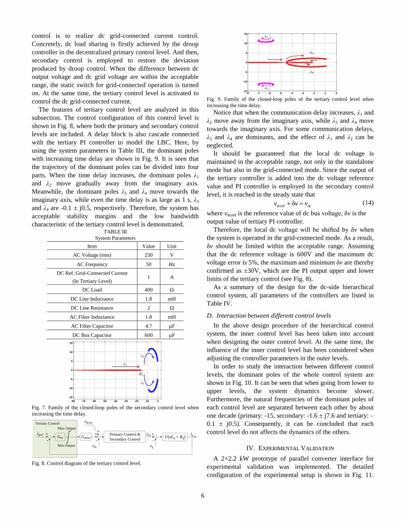
with increasing time delay are shown in Fig. 9. It is seen that
the trajectory of the dominant poles can be divided into four
parts. When the time delay increases, the dominant poles λ1
and λ2 move gradually away from the imaginary axis.
Meanwhile, the dominant poles λ3 and λ4 move towards the
imaginary axis, while even the time delay is as large as 1 s, λ3
and λ4 are -0.1 ± j0.5, respectively. Therefore, the system has
acceptable stability margins and the low bandwidth
characteristic of the tertiary control level is demonstrated. TABLE III
System Parameters
Item Value Unit
AC Voltage (rms) 230 V
AC Frequency 50 Hz
DC Ref. Grid-Connected Current
(In Tertiary Level) 1 A
DC Load 400 Ω
DC Line Inductance 1.8 mH
DC Line Resistance 2 Ω
AC Filter Inductance 1.8 mH
AC Filter Capacitor 4.7 µF
DC Bus Capacitor 600 µF
-80 -70 -60 -50 -40 -30 -20 -10 0
-15
-10
-5
0
5
10
15
λ1
λ2
λ3
PI
Fig. 7. Family of the closed-loop poles of the secondary control level when
increasing the time delay.
vdcigref +
-
Primary Control &
Secondary Control
+
-
vg
1/(sLg + Rg)ig
GPI Gdelay+
-
vdcref
+
vdc
Tertiary Control
Max Output
Min Output
Fig. 8. Control diagram of the tertiary control level.
-8 -7 -6 -5 -4 -3 -2 -1 0-15
-10
-5
0
5
10
15
λ1
λ2
λ3
λ4
Fig. 9. Family of the closed-loop poles of the tertiary control level when
increasing the time delay.
Notice that when the communication delay increases, λ1 and
λ2 move away from the imaginary axis, while λ3 and λ4 move
towards the imaginary axis. For some communication delays,
λ3 and λ4 are dominants, and the effect of λ1 and λ2 can be
neglected.
It should be guaranteed that the local dc voltage is
maintained in the acceptable range, not only in the standalone
mode but also in the grid-connected mode. Since the output of
the tertiary controller is added into the dc voltage reference
value and PI controller is employed in the secondary control
level, it is reached in the steady state that
dcref dcδv v v (14)
where vdcref is the reference value of dc bus voltage, δv is the
output value of tertiary PI controller.
Therefore, the local dc voltage will be shifted by δv when
the system is operated in the grid-connected mode. As a result,
δv should be limited within the acceptable range. Assuming
that the dc reference voltage is 600V and the maximum dc
voltage error is 5%, the maximum and minimum δv are thereby
confirmed as ±30V, which are the PI output upper and lower
limits of the tertiary control (see Fig. 8).
As a summary of the design for the dc-side hierarchical
control system, all parameters of the controllers are listed in
Table IV.
D. Interaction between different control levels
In the above design procedure of the hierarchical control
system, the inner control level has been taken into account
when designing the outer control level. At the same time, the
influence of the inner control level has been considered when
adjusting the controller parameters in the outer levels.
In order to study the interaction between different control
levels, the dominant poles of the whole control system are
shown in Fig. 10. It can be seen that when going from lower to
upper levels, the system dynamics become slower.
Furthermore, the natural frequencies of the dominant poles of
each control level are separated between each other by about
one decade (primary: -15, secondary: -1.6 ± j7.6 and tertiary: –
0.1 ± j0.5). Consequently, it can be concluded that each
control level do not affects the dynamics of the others.
IV. EXPERIMENTAL VALIDATION
A 2×2.2 kW prototype of parallel converter interface for
experimental validation was implemented. The detailed
configuration of the experimental setup is shown in Fig. 11.

7
The parameters of the system are the same as those chosen in
the theoretical analysis, as listed in Table III. TABLE IV
Controller Parameters of the DC-side Hierarchical Control System
Item Value Unit
Primary Control Level
AC Current
Controller
Proportional Term 16 -
Resonant Term 2000 -
DC Voltage
Controller
Proportional Term 1.3 -
Integral Term 6 -
Droop Controller 6 Ω
Communication Bandwidth Decentralized
Secondary Control Level
DC-Bus Voltage
Controller
Proportional Term 0.003 -
Integral Term 13 -
Communication Bandwidth 500 Hz
Tertiary Control Level
DC Current
Controller
Proportional Term 0.6 -
Integral Term 20 -
Communication Bandwidth 250 Hz
-20 -18 -16 -14 -12 -10 -8 -6 -4 -2 0-8
-6
-4
-2
0
2
4
6
8
-1.6 + j7.6
-1.6 – j7.6
-0.1 + j0.5
-0.1 - j0.5
-15
TertiarySecondaryPrimary
Bandwidth Decreasing
Fig. 10. Dominant poles of different control levels.
In the primary control level, voltage and current controllers
are tested first without droop control. The local dc voltage
waveform is shown in Fig. 12 and the corresponding local ac
current response is shown in Fig. 13. Then, droop control is
verified. When droop controller is activated, the dc current is
equally shared, while the deviation in the dc voltage appears,
as shown in Fig. 14 and 15. After testing equal dc sharing,
proportional dc current sharing is performed. When Rd1=6Ω
and Rd2=12Ω, I-V curve for proportional current sharing is
drawn in Fig. 16. For a certain value of dc voltage, the
corresponding current values of Converter #1 and Converter
#2 can be got in Fig. 16. It can be reached that idc1/idc2 =
Rd2/Rd1 = 2, so the proportional dc current sharing can be
realized.
In the secondary control level, in order to flexibly regulate
the communication delay in the experiment, a sample & hold
block is employed in the experimental program. The output
value of the secondary or tertiary controller is transferred to
each converter at a low frequency by using the sampling &
hold block. The output value of the secondary or tertiary
controller at the beginning of each transmission interval is held
until the next transmission starts. When t = 0, the secondary
control level turns on. The effect of secondary controller is
shown in Fig. 17. It can be seen that the deviation produced by
the droop controller can be restored by secondary dc voltage
controller. The load regulation is also tested by changing the
load resistance from 400Ω to 133Ω, as shown in Fig. 18. It can
be seen that by using the secondary control level, the dc bus
voltage can be kept stable during the transient process of load
step. The output waveform of the secondary controller is
shown in Fig. 19. For comparison, the output waveform of the
secondary controller without the sampling and hold block is
also shown. It is seen from the stair-shape that the LBC is
reached.
In the tertiary control level, similar to the secondary control
level, the sample & hold unit is also employed to model the
LBC. When the dc voltage is guaranteed to be within the
acceptable range, the tertiary control is activated and the static
switch for grid-connected operation is turned on. A
bidirectional dc source should be provided to implement the dc
grid. Therefore, a third ac-dc converter was adopted to achieve
the above dc source. For safety consideration, the dc voltage
reference value is lowered down to 600V in the dc grid-
connected test. Fig. 20 shows the dc grid-connected current
regulated by the tertiary PI controller. The dc current reference
value is set to 0 – 1A – -1A – 0. When the dc grid-connected
current is changing, the dc voltage waveform is exhibited in
Fig. 21 accordingly. It is shown that dc current can be
controlled to follow the reference value as expected.
Meanwhile, the steady value of dc voltage is guaranteed to be
within the acceptable range (570 V ≤ vdc ≤ 630 V). The output
waveform of the tertiary controller is exhibited in Fig. 22. It is
shown from the stair-shape that the LBC is reached.
V. CONCLUSION
Different operation modes of a hybrid microgrid are
discussed in this paper. Focusing on the interfacing converters
between ac bus and dc bus, a dc-side hierarchical control
system is designed and evaluated in this paper to analyze both
standalone and grid-connected dc operation modes. In the
decentralized primary control level of the hierarchical control
system, ac current and dc voltage control are accomplished.
For dc output load current sharing, droop controller is
employed. Both equal and proportional current sharing are
realized. In the secondary control level, with the common PI
controller, dc bus voltage deviation caused by the droop
control in the primary control level is restored. Meanwhile,
common tertiary control level is involved to control the grid-
connected current in the dc-side grid-connected operation. It
has been demonstrated that each control level does not
interfere with each other. Thus, the dynamics of different
control levels are decoupled.

8
idc1
RL
AC
DC
AC
DC
uabc Control System
Based on dSPACE1103
iabc2iabc1
idc2PWM2PWM1 udc
ig
Fig. 11. System configuration of the prototype.
DC
Volt
age (
V)
Time (s) Fig. 12. Local dc voltage response.
AC
Cu
rren
t (A
)
Time (s) Fig. 13. Local ac current response.
DC
Cu
rren
t (A
)
Time (s) Fig. 14. Equal sharing of dc output current by droop control.
≈5V
DC
Volt
age
(V)
Time (s) Fig. 15. DC voltage deviation produced by droop control.
0 0.2 0.4 0.6 0.8 1 1.2 1.4 1.6 1.8 2660
665
670
675
680
685
690
695
700
705
data1
data2
data3
data4
Simulation PointExperiment Point
vdc-Rd1idc1
vdc-Rd2idc2
705
700
695
690
685
680
675
670
665
6600 0.2 1.80.4 0.6 0.8 1 1.2 1.4 1.6 2
DC Current (A)
DC
Vo
lta
ge
(V)
Fig. 16. Simulation and experimental test of dc current proportional sharing
with different load currents.
DC
Vo
lta
ge
(V)
5V
Time (s) Fig. 17. DC voltage restoration of secondary control.
8.5V
DC
Volt
age
(V)
Time (s) Fig. 18. Load step response of dc voltage secondary control.
Ou
tpu
t o
f S
eco
nd
ary
Co
ntr
oll
er
Time (s) Fig. 19. Output of dc voltage secondary controller.

9
DC
Gri
d-C
on
nec
ted
Cu
rren
t (A
)
Time (s) Fig. 20. DC grid-connected current with tertiary control.
DC
Vo
lta
ge
(V)
Time (s) Fig. 21. DC voltage with tertiary control.
Time (s)
Ou
tpu
t o
f T
erti
ary
Co
ntr
oll
er
Fig. 22. Output of dc grid-connected current tertiary controller.
VI. REFERENCES
[1] E. Bossanyi, Wind Energy Handbook. New York: Wiley, 2000.
[2] T. Markvart, Solar Electricity, 2nd ed. New York: Wiley, 2000.
[3] R. Lasseter, A. Akhil, C. Marnay, J. Stevens, J. Dagle, et al, “The certs
microgrid concept - white paper on integration of distributed energy
resources,” Technical report, U.S. Department of Energy, 2002.
[4] F. Blaabjerg, Z. Chen and S. B. Kjaer, “Power electronics as efficient
interface in dispersed power generation systems,” IEEE Trans. Power
Electron., vol. 19, no. 5, pp. 1184-1194, 2004.
[5] J. M. Carrasco, L. G. Franquelo, J. T. Bialasiewicz, et al, “Power-
electronic systems for the grid integration of renewable energy sources: a
survey,” IEEE Trans. Ind. Electron., vol. 53, no. 4, pp. 1002-1016,
2006.
[6] C. T. Lee, C. C. Chuang, C. C. Chu and P. T. Cheng, “Control strategies
for distributed energy resources interface converters in the low voltage
microgrid,” in Proc. IEEE ECCE, 2009, pp. 2022-2029.
[7] K. Kurohane, T. Senjyu, A. Yona, et al, “A hybrid smart AC/DC power
system,” IEEE Trans. Smart Grid, vol. 1, no. 2, pp. 199-204, 2010.
[8] X. Liu, P. Wang and P. C. Loh, “A hybrid AC/DC microgrid and its
coordination control,” IEEE Trans. Smart Grid, vol. 2, no. 2, pp. 278-
286, 2011.
[9] Z. Ye, K. Xing, S. Mazumder, D. Borojevic and F. C. Lee, “Modeling
and control of parallel three-phase PWM boost rectifiers in PEBB-based
DC distributed power systems,” in Proc. IEEE APEC, 2008, pp. 1126-
1132.
[10] J. M. Guerrero, L. Hang and J. Uceda, “Control of distributed
uninterruptible power supply systems,” IEEE Trans. Ind. Electron., vol.
55, no. 8, pp. 2845-2859, 2008.
[11] J. M. Guerrero, J. C. Vasquez, J. Matas, M. Castilla, et al, “Control
strategy for flexible microgrid based on parallel line-interactive UPS
systems,” IEEE Trans. Ind. Electron., vol. 56, no. 3, pp. 726-736, 2009.
[12] X. Lu, J. M. Guerrero, K. Sun, J. C. Vasquez. “An improved droop
control method for dc microgrids based on low bandwidth
communication with dc bus voltage restoration and enhanced current
sharing accuracy,” IEEE Trans. Power Electron., to appear.
[13] Y. Li and Y. W. Li, “Power management of inverter interfaced
autonomous microgrid based on virtual frequency-voltage frame,” IEEE
Trans. Smart Grid, vol. 2, no. 1, pp. 30-40, 2011.
[14] A. P. Martins, A. S. Carvalho and A. S. Araújo, “Design and
implementation of a current controller for the parallel operation of
standard UPSs,” in Proc. IEEE IECON, 1995, pp. 584-589.
[15] J. Rajagopalan, K. Xing, Y. Guo and F. C. Lee, “Modeling and dynamic
analysis of paralleled dc/dc converters with master-slave current sharing
control,” in Proc. IEEE APEC, 1996, pp.678-684.
[16] T. F. Wu, Y. K. Chen and Y. H. Huang, “3C strategy for inverters in
parallel operation achieving an equal current distribution,” IEEE Trans.
Ind. Electron., vol.47, no.2, pp.273-281, 2000.
[17] X. Sun, Y. S. Lee and D. H. Xu, “Modeling, analysis, and
implementation of parallel multi-inverter systems with instantaneous
average-current-sharing scheme,” IEEE Trans. Power Electron., vol.18,
no.3, pp. 844-856, 2003.
[18] P. M. Kanabar, M. G. Kanabar, W. El-Khattam, T. S. Sidhu, et al,
“Evaluation of communication technologies for IEC 61850 based
distribution automation system with distributed energy resources,” in
Proc. IEEE PES, 2009, pp. 1-8.
[19] S. Anand, B. G. Fernandes and J. M. Guerrero, “Distributed control to
ensure proportional load sharing and improve voltage regulation in low
voltage DC microgrids,” IEEE Trans. Power Electron., vol. 28, no. 4,
pp. 1900-1913, 2013.
[20] Y. Zhang and H. Ma, “Theoretical and experimental investigation of
networked control for parallel operation of inverters,” IEEE Trans. Ind.
Electron., vol. 59, no. 4, pp. 1961-1970, 2012.
[21] J. Anatory, N. Theethayi, R. Thottappillil, M. M. Kissaka, et al, “The
influence of load impedance, line length, and branches on underground
cable power-line communications (PLC) systems,” IEEE Trans. Power
Del., vol. 23, no. 1, pp. 180-187, 2008.
[22] A. Pinomaa, J. Ahola and A. Kosonen, “Power-line communication-
based network architecture for LVDC distribution system,” in Proc.
IEEE Int. Symp. Power Line Commun. Appl., 2011, pp. 358-363.
[23] S. M. Ashabani and Y. A. I. Mohamed, “A flexible control strategy for
grid-connected and islanded microgrids with enhanced stability using
nonlinear microgrid stabilizer,” IEEE Trans. Smart Grid, vol. 3, no. 3,
pp. 1291-1301, 2012.
[24] D. Dong, T. Thacker, I. Cvetkovic, et al, “Modes of operation and
system-level control of single-phase bidirectional PWM converter for
microgrid systems,” IEEE Trans. Smart Grid, vol. 3, no. 1, pp. 93-104,
2012.
[25] Z. Jiang and X. Y, “Hybrid dc- and ac-linked microgrids: towards
integration of distributed energy resources,” in Proc. IEEE Energy 2030,
2008, pp. 1-8.
[26] F. Shahnia, R. Majumder, A. Ghosh, G. Ledwich, et al, “Operation and
control of a hybrid microgrid containing unbalanced and nonlinear
loads,” Electric Power Systems Research, vol. 80, no. 8, pp. 954-965,
2010.
[27] P. C. Loh, D. Li, Y. Chai and F. Blaabjerg, “Autonomous operation of
hybrid microgrid with ac and dc subgrids,” IEEE Trans. Power
Electron., vol. 28, no. 5, pp. 2214-2223, 2013.
[28] J. M. Guerrero, J. C. Vasquez, J. Matas, et al, “Hierarchical control of
droop-controlled AC and DC microgrids - a general approach toward
standardization,” IEEE Trans. Ind. Electron., vol. 58, no. 1, pp. 158-
172, 2011.
[29] H. H. Huang, C. Y. Hsieh, J. Y. Liao and K. H. Chen, “Adaptive droop
resistance technique for adaptive voltage positioning in boost DC-DC
converters,” IEEE Trans. Power Electron., vol. 26, no. 7, pp. 1920-
1932, 2011.
[30] C. Klumpner, M. Liserre and F. Blaabjerg, “Improved control of an
active-front-end adjustable speed drive with a small dc-link capacitor
under real grid conditions,” in Proc. IEEE PESC, 2004, pp. 1156-1162.

10
Xiaonan Lu (S’11) was born in Tianjin, China, 1985.
He received the B.E. degree in 2008, in electrical
engineering from Tsinghua University, Beijing,
China, where he is currently working towards his
Ph.D. degree. From Sep. 2010 to Aug. 2011 he was a
guest Ph.D. student at Department of Energy
Technology, Aalborg University, Denmark.
His research interests are control of power electronics
interfacing converters for renewable generation
systems and microgrids, multilevel converters, and
matrix converters.
Mr. Lu is a student member of IEEE PELS Society.
Josep M. Guerrero (S’01-M’04-SM’08) received
the B.S. degree in telecommunications engineering,
the M.S. degree in electronics engineering, and the
Ph.D. degree in power electronics from the
Technical University of Catalonia, Barcelona, in
1997, 2000 and 2003, respectively. He was an
Associate Professor with the Department of
Automatic Control Systems and Computer
Engineering, Technical University of Catalonia,
teaching courses on digital signal processing, field-
programmable gate arrays, microprocessors, and
control of renewable energy. In 2004, he was responsible for the Renewable
Energy Laboratory, Escola Industrial de Barcelona. Since 2011, he has been a
Full Professor with the Department of Energy Technology, Aalborg
University, Aalborg East, Denmark, where he is responsible for the microgrid
research program. From 2012 he is also a guest Professor at the Chinese
Academy of Science and the Nanjing University of Aeronautics and
Astronautics. His research interests is oriented to different microgrid aspects,
including power electronics, distributed energy-storage systems, hierarchical
and cooperative control, energy management systems, and optimization of
microgrids and islanded minigrids. Prof. Guerrero is an Associate Editor for
the IEEE TRANSACTIONS ON POWER ELECTRONICS, the IEEE
TRANSACTIONS ON INDUSTRIAL ELECTRONICS, and the IEEE
Industrial Electronics Magazine, and an Editor for the IEEE
TRANSACTIONS on SMART GRID. He has been Guest Editor of the IEEE
TRANSACTIONS ON POWER ELECTRONICS Special Issues: Power
Electronics for Wind Energy Conversion and Power Electronics for
Microgrids; the IEEE TRANSACTIONS ON INDUSTRIAL ELECTRONICS
Special Sections: Uninterruptible Power Supplies systems, Renewable Energy
Systems, Distributed Generation and Microgrids, and Industrial Applications
and Implementation Issues of the Kalman Filter; and the IEEE
TRANSACTIONS on SMART GRID Special Issue on Smart DC Distribution
Systems. He was the chair of the Renewable Energy Systems Technical
Committee of the IEEE Industrial Electronics Society.
Kai Sun (M’12) was born in Beijing, China, 1977.
He received the B.E., M.E., and Ph.D. degrees in
electrical engineering all from Tsinghua University,
Beijing, China, in 2000, 2002, and 2006,
respectively. In 2006, he joined the faculty of
Tsinghua University as a Lecturer of Electrical
Engineering, where he is currently an Associate
Professor. From Sep. 2009 to Aug. 2010 he was a
Visiting Scholar at Department of Energy
Technology, Aalborg University, Denmark.
He has authored more than 80 technical papers,
including 9 international journal papers. His main research interests are power
converters for renewable generation systems and AC motor drives. Dr. Sun
received the Delta Young Scholar Award in 2013.
Juan C. Vasquez (M’12) received the B.S. degree
in Electronics Engineering from Autonoma
University of Manizales, Colombia in 2004 where
he has been teaching courses on digital circuits,
servo systems and flexible manufacturing systems.
In 2009, He received his Ph.D. degree from the
Technical University of Catalonia, Barcelona,
Spain in 2009 at the Department of Automatic
Control Systems and Computer Engineering, from
Technical University of Catalonia, Barcelona
(Spain), where he worked as Post-doc Assistant
and also teaching courses based on renewable
energy systems. Currently, he is an Assistant Professor at Aalborg University
in Denmark. His research interests include modeling, simulation, networked
control systems and optimization for power management systems applied to
Distributed Generation in AC/DC Microgrids.
Remus Teodorescu (S’96-A’97-M’99-SM’02-
F’12) received the Dipl.Ing. degree in electrical
engineering from the Polytechnic University of
Bucharest, Bucharest, Romania, in 1989 and the
Ph.D. degree in power electronics from the
University of Galați, Galați, Romania, in 1994.
In 1998, he joined the Power Electronics Section,
Department of Energy Technology, Aalborg
University, Aalborg, Denmark, where he is
currently a Professor. He has more than 200 papers
published, one book, entitled Grid Converters for
Photovoltaic and Wind Power Systems (New York, NY, USA: Wiley, 2011),
and five patents. His research interests include the design and control of
power converters used in photovoltaics and wind power systems, grid
integration with wind power, medium-voltage converters, HVDC/FACTS,
and energy storage.
Dr. Teodorescu was an Associate Editor for IEEE TRANSACTIONS ON
POWER ELECTRONICS LETTERS. He is the Chair of the IEEE Danish
Joint Industrial Electronics/Power Electronics/Industry Applications Society
Chapter. He is the Founder and Coordinator of the Green Power Laboratory,
Aalborg University, focusing on the development and testing of grid
converters for renewable energy systems. He is the Coordinator of Vestas
Power Program, involving ten Ph.D. students and Guest Professors in the
areas of power electronics, power systems, and energy storage.
(S’96–A’97–M’99–SM’02–F’12)
Lipei Huang was born in Jiangsu, China, 1946. He
received the B.E. and M.E. degrees in electrical
engineering from Tsinghua University, Beijing,
China, in 1970 and 1982, respectively, and the
Ph.D. degree from Meiji University, Tokyo, Japan,
in 1996. In 1970, he joined the Department of
Electrical Engineering, Tsinghua University. Since
1994, he has been a Professor in the Department of
Electrical Engineering, Tsinghua University. In
1987, he was a Visiting Scholar of Electrical
Engineering at the Tokyo Institute of Technology,
for three months, and at Meiji University, Kawasaki, Japan, for nine months.
He joined the research projects of K. Matsuse Laboratory, Department of
Electrical Engineering, Meiji University, Kawasaki, Japan, as a Visiting
Professor in 1993.
He has authored more than 100 technical papers and holds 7 patents. His
research interests are in power electronics and adjustable-speed drives.
Prof. Huang received the Education Awards from the China Education
Commission and Beijing People’s Government in 1997. From 2001 to 2003
he was a Delta Scholar.