Embed Size (px)
Citation preview
Aalborg Universitet
A Decentralized Control Architecture applied to DC Nanogrid Clusters for RuralElectrification in Developing Regions
Nasir, Mashood; Jin, Zheming; Khan, Hassan; Zaffar, Nauman; Vasquez, Juan; Guerrero,Josep M.Published in:IEEE Transactions on Power Electronics
DOI (link to publication from Publisher):10.1109/TPEL.2018.2828538
Publication date:2019
Document VersionAccepted author manuscript, peer reviewed version
Link to publication from Aalborg University
Citation for published version (APA):Nasir, M., Jin, Z., Khan, H., Zaffar, N., Vasquez, J., & Guerrero, J. M. (2019). A Decentralized ControlArchitecture applied to DC Nanogrid Clusters for Rural Electrification in Developing Regions. IEEE Transactionson Power Electronics, 34(2), 1773-1785. [8341807]. https://doi.org/10.1109/TPEL.2018.2828538
General rightsCopyright and moral rights for the publications made accessible in the public portal are retained by the authors and/or other copyright ownersand it is a condition of accessing publications that users recognise and abide by the legal requirements associated with these rights.
? Users may download and print one copy of any publication from the public portal for the purpose of private study or research. ? You may not further distribute the material or use it for any profit-making activity or commercial gain ? You may freely distribute the URL identifying the publication in the public portal ?
Take down policyIf you believe that this document breaches copyright please contact us at [email protected] providing details, and we will remove access tothe work immediately and investigate your claim.

0885-8993 (c) 2018 IEEE. Personal use is permitted, but republication/redistribution requires IEEE permission. See http://www.ieee.org/publications_standards/publications/rights/index.html for more information.
This article has been accepted for publication in a future issue of this journal, but has not been fully edited. Content may change prior to final publication. Citation information: DOI 10.1109/TPEL.2018.2828538, IEEETransactions on Power Electronics
Abstract — DC microgrids built through bottom-up approach
are becoming popular for swarm electrification due to their
scalability and resource sharing capabilities. However, they
typically require sophisticated control techniques involving
communication among the distributed resources for stable and
coordinated operation. In this work, we present a
communication-less strategy for the decentralized control of a
PV/battery-based highly distributed DC microgrid. The
architecture consists of clusters of nanogrids (households),
where each nanogrid can work independently along with
provisions of sharing resources with the community. An
adaptive I-V droop method is used which relies on local
measurements of SOC and DC bus voltage for the coordinated
power sharing among the contributing nanogrids. PV
generation capability of individual nanogrids is synchronized
with the grid stability conditions through a local controller
which may shift its modes of operation between maximum
power point tracking mode and current control mode. The
distributed architecture with the proposed decentralized control
scheme enables a) scalability and modularity in the structure, b)
higher distribution efficiency, and c) communication-less, yet
coordinated resource sharing. The efficacy of the proposed
control scheme is validated for various possible power sharing
scenarios using simulations on MATLAB/Simulink and
hardware in loop facilities at microgrid laboratory in Aalborg
University.
Index Terms — DC Microgrid, DC Nanogrid, Distributed
Generation, Distributed Storage, Droop Control, Rural-
Electrification.
I. INTRODUCTION
ccording to International Energy Agency (IEA), around
1.2 billion people (16% of the global population) do not
have access to electricity. More than 95% of those living
without electricity are the residents of sub-Saharan African
and developing Asian countries, while around 80% of them
reside in rural areas [1]. Electrification of these remote areas
This work was supported by International Research Support Initiative
Program (IRSIP) by Higher Education Commission (HEC) of Pakistan and collaborated between Department of Electrical Engineering at Lahore
University of Management Sciences (LUMS) and Department of Energy
Technology at Aalborg University (AAU). M. Nasir, H.A.Khan and N.A. Zaffar are with Department of Electrical
Engineering at LUMS, Lahore, Cantt 54792, Pakistan. (e-mail: 14060018;
hassan,khan; [email protected]). Z.Jin, J.C.Vasquez and J.M.Guerrero are with Department of Energy
Technology at AAU, Aalborg 9220, Denmark. (e-mail: zhe; juq;
via national grid is unviable due to large up-front cost
requirements. Electrification of these villages via islanded
microgrids has seen an unprecedented growth in the recent
years due to various factors mainly including a) lower up-
front cost in comparison to national grid interconnection, b)
successful business models for energy micro-financing, and
c) advancements in power electronics, PV and battery
technologies [2-4]. PV/battery-based DC microgrids have
gain more popularity due to a) natural availability of solar
energy in most of under-developed areas (most regions in
Southeast Asia and Africa receive abundant sunlight i.e.
above 5.5 kWhr/m2/day), b) higher efficiency of DC
distribution in comparison to AC distribution c) wide market
availability and large penetration of highly efficient DC
loads, d) gradually decreasing prices of PV panels and
batteries, and e) omission of redundant AC/DC inter-
conversion stages from generation to utilization [2, 5-8].
Prominent practical implementations for rural
electrification through PV/battery-based islanded DC
microgrids include micro-solar plants in Chhattisgarh,
Sunderbans and Lakshadweep in India [9, 10]. Another very
successful commercial scale project is Mera Gao Power
(MGP) in India, where each subscriber may consume up to
5W of DC electricity (enough to power an LED light and a
mobile-phone charging point) for 8-hrs per day. It is reported
that MGP has over 10,000 subscribing households spread
across 400 villages [11, 12]. The above-mentioned
deployments utilize centralized architecture with top-down
approach, where PV generation and battery storage is kept at
a centralized location. This energy is delivered to subscribing
households via distribution conductors and therefore,
distribution losses are associated with the delivery of energy.
The main advantage of central architecture is that power
delivery can be controlled from a single point; therefore, this
it offers simplicity in terms of operation, control and
maintenance. However, this architecture is not readily
scalable in terms of future expansions due to its non-modular
nature. Further, distribution efficiency is a major limitation
for centralized architectures, as distribution losses become
significant at low distribution voltages, thin conductor sizes
and higher power levels [13]. Moreover, such architectures
require relatively higher initial capital investment due to top-
down sizing requirements [14].
Various distributed architectures for PV/battery-based
islanded DC microgrids have been proposed in literature.
Distributed architectures with bottom-up approach enable
A Decentralized Control Architecture applied to DC
Nanogrid Clusters for Rural Electrification in
Developing Regions
Mashood Nasir, Zheming Jin, Hassan A Khan, Member, IEEE, Nauman A. Zaffar, Member, IEEE,
Juan. C. Vasquez, Senior Member, IEEE and Josep M.Guerrero, Fellow, IEEE
A

0885-8993 (c) 2018 IEEE. Personal use is permitted, but republication/redistribution requires IEEE permission. See http://www.ieee.org/publications_standards/publications/rights/index.html for more information.
This article has been accepted for publication in a future issue of this journal, but has not been fully edited. Content may change prior to final publication. Citation information: DOI 10.1109/TPEL.2018.2828538, IEEETransactions on Power Electronics
organic growth of microgrid, thereby, empowering local
communities for sustainable development [14]. Wardah et al.
[15] presented a partially distributed architecture, in which
peer to peer electricity sharing was enabled by GSM based
through power management units (PMU’s). Similarly,
Madduri et al. [16, 17] proposed a PV/battery-based central
generation and distributed storage architecture, with the
provision of local batteries in individual households. The
advantages of distributed architectures are mainly reduction
in distribution losses and modularity in structure. However,
coordinated power sharing among the distributed resources
becomes extremely challenging. Several strategies for
hierarchical and supervisory control of DC microgrids have
been proposed in [18-21]. However, these require an extra
layer of sensing and communication, which enhances the
cost and complexity of the system.
Thus, for PV/battery-based rural electrification, a
distributed architecture having minimum distribution losses,
modularly scalable structure and communication-less control
is highly desirable. Mashood et al. [22] presented a PV-based
distributed generation and distributed storage architecture
(DGDSA) of DC microgrid for rural electrification.
However, the hysteretic based voltage droop algorithm
presented in [22] depends upon the perturbations in duty
cycle. A very small perturbation in duty makes the dynamics
of system very slow to achieve the desired power sharing,
while a higher perturbation in duty cycle may lead to
instability. In such a scheme, resource sharing capability
among the distributed resources is uncoordinated i.e. all
nanogrids share or demand uniform amount of power
regardless of their current states generation and storage.
Xiaonan et al. [23] developed an adaptive dual loop droop
control (inner current loop and outer voltage loop) on the
basis of state of charge (SOC) balancing. This adaptive droop
considers power sharing proportional to the battery SOC
index during power supply mode (battery discharge mode).
However, it does not consider power sharing in proportional
to the SOC index during charging mode of the battery.
Therefore, all batteries get charged with the same power
independent of their state of charge or resource availability
for battery charging. If such a scheme is applied on DGDSA
of DC microgrid presented in [22] having local loads, there
will be redundant distribution losses for un-wanted SOC
balancing. Ideally, in such architectures, it is desirable that if
SOC is above a certain threshold, it must be maintained to
that level rather than undesired balancing. Moreover,
Zheming et al. [24] showed that the V-I dual loop droop
control exhibit slower dynamics in comparison to I-V droop,
therefore, it cannot achieve fast power sharing among the
distributed resources.
Therefore, in order to rectify these limitations of
decentralized control schemes for distributed DC microgrids,
we present an adaptive I-V droop method for the
decentralized control of a PV-based DGDSA of DC
microgrid suitable for rural electrification. The resource
sharing among the contributing nanogrids is kept in
proportion to the availability of resources for both operation
modes i.e. during supply and demand of the power to or from
the nanogrid (charging and discharging of the battery). This
power sharing proportional to resource availability is
achieved by using an adaptive I-V droop algorithm, which
may adjust its droop based upon the local measurement of
DC bus voltage and SOC of the battery. Moreover, the
proposed control scheme ensures fast dynamics and is
capable to deal with the extreme operating conditions by
synchronizing PV generation capability of individual
nanogrids with the local load requirements and grid stability
conditions through a local controller, which may shift its
modes of operation between MPPT mode and current control
mode. Since, the proposed control scheme relies on the local
measurements of load current, PV generation, battery SOC
and DC bus voltage; therefore, does not require
communication for the coordinated power sharing among the
contributing nanogrids. Thus, with the proposed adaptive
control scheme, PV based DGDSA combines the advantages
of both of the existing architectures i.e. scalability,
modularity, lower distribution losses, along with robust,
coordinated and communication-less decentralized control.
Thus, such a decentralized system can be considered as an
ideal candidate for future deployments of rural electrification
projects in developing regions.
The rest of this paper is organized as follows. In section
II, the architecture of the proposed microgrid as an
interconnection of multiple nanogrids is presented. In section
III, power electronic interface and control schemes is
presented. Section IV presents the objectives for various
possible scenarios of coordinated control. Simulation and
hardware results are presented in section V. Based upon the
results and discussions, a conclusion is drawn in section VI.
II. DISTRIBUTED GENERATION AND DISTRIBUTED STORAGE
ARCHITECTURE OF DC MICROGRID
The combination of PV generation, battery storage, local
DC loads and DC-DC converters in an individual household
formulates a nanogrid. Local generation and local storage
allows the nanogrid to work independently even if the grid is
unavailable and has many practical advantages compared to
central generation based systems. A cluster of N multiple
nanogrids is interconnected via a DC-link to formulate the
distributed generation distribute storage architecture
(DGDSA) of a DC microgrid as shown in Fig. 1. An
individual nanogrid is therefore considered a basic building
block, whose modular replication and subsequent DC-link
integration yields scalability in the architecture. Each
nanogrid operates independently when it is self-sufficient in
its resources and resource sharing among multiple nanogrids
is enabled only when an individual nanogrid has either
access or deficiency of resources. Therefore, energy losses
with the distribution of energy in DGDSA are limited in
comparison to other partially distributed or centralized
architectures, where generated energy has to be distributed
all the way from centralized generation point to individual
households [13, 22]. Further, DGDSA has the capability to
aggregate power from multiple nanogrids for driving
community loads. The supply of power for large communal
loads is otherwise expensive and unsustainable in limited
rural electrification projects [13, 22].

0885-8993 (c) 2018 IEEE. Personal use is permitted, but republication/redistribution requires IEEE permission. See http://www.ieee.org/publications_standards/publications/rights/index.html for more information.
This article has been accepted for publication in a future issue of this journal, but has not been fully edited. Content may change prior to final publication. Citation information: DOI 10.1109/TPEL.2018.2828538, IEEETransactions on Power Electronics
DC
BUS
Community Load
Nanogrid 1/ Household 1
Nanogrid 2/ Household 2
Nanogrid N/ Household N
Circuitbreaker
Step DownConverter
DC Loads Battery
BidirectionalConverter
Roof Mounted PV Panel
Step DownConverter
DC Loads Battery
BidirectionalConverter
Roof Mounted PV Panel
Step DownConverter
DC Loads Battery
BidirectionalConverter
Roof Mounted PV Panel
Circuitbreaker
Circuitbreaker
Circuitbreaker
Fig. 1. A cluster of multiple nanogrids interconnected via DC bus
formulating the DGDSA of PV/battery-based DC microgrid.
III. PROPOSED DECENTRALIZED CONTROL SCHEME FOR
COMMUNICATION-LESS AND COORDINATED RESOURCE
SHARING AMONG THE CLUSTER OF MULTIPLE NANOGRIDS
In the proposed decentralized scheme, each individual
nanogrid is responsible for coordinated power sharing among
the cluster without any physical communication. Power
electronic interface for the formulation of an individual
nanogrid is shown in Fig. 2a, which shows local PV
generation, battery storage, household load and two DC-DC
converters for power processing in an individual nanogrid.
Index i is representing an arbitrary nanogrid in a cluster of N
nanogrids. Battery acts as buffer between converter 1 of ith
nanogrid (Conv1i) and converter 2 of ith
nanogrid (Conv2i),
and is responsible to keep the voltage fixed at the local bus to
which household load is connected. Therefore, battery acts as
a point of common coupling at which the terminals of load
and both converters are connected. Conv1i is an isolated
bidirectional converter and is responsible for controlled
power sharing among nanogrids through interconnected DC
bus. Distribution voltage in such low voltage direct current
(LVDC) microgrids is dictated by DC bus voltage and is a
key factor for achieving optimal distribution efficiency.
Distribution at higher voltage is generally more efficient
from the prospective of line losses and voltage drops at rear
end [22]. Therefore, DC bus voltage is kept higher in
comparison to battery voltage or household load voltage.
This is achieved through converter (Conv1i) which interfaces
the battery with the DC bus. Moreover, to enable two-way
power flow between battery of individual nanogrid and DC
bus, this converter is made bi-directional in nature as shown
in Fig.1 and Fig. 2. The advantage of making it as an isolated
converter is twofold, i.e. a) it provides isolation between grid
and battery and b) higher ratio of DC/DC voltage conversion
can be achieved for implementing higher levels of LVDC,
i.e. 120V, 230V or 380V [22]. Converter 2 (Conv2i) on the
other hand is a step down converter and is responsible for
optimal power extraction from PV panels.
The communication-less coordination among the
distributed resources is achieved through the simultaneous
control of each individual nanogrid via control scheme shown
in Fig. 2b. The control scheme shown in Fig. 2b utilizes and
adaptive algorithm (shown in Fig. 2c), for switching of conv1i
based upon the local measurements of bus voltage VB and
battery state of charge SOCi. This control scheme is also
responsible for switching of Conv2i between MPPT and
current control mode based upon the local measurements of
household load, PV generation and battery SOCi. Various
possible modes of operation for Conv1i and Conv2i for each
individual nanogrid as shown in Fig. 2c are discussed in the
following subsections.
A. Multi-mode Adaptive Control Scheme for Bidirectional
Converter (Conv1i) Integrated with DC bus
For each nanogrid i, control mode for its bus interfaced
converter Conv1i is determined by an adaptive controller on
the basis of bus voltage VB and state of charge of its battery
SOCi. The SOCi of the battery is approximated by a simple
Columb counting method, as governed by (1) and is based
upon the ideal energy balance at ith
local bus given by (2):
tdIIIVC
SOCtSOC
T
L
i
load
i
in
i
b
i
i
ii 0
1
0 (1)
tdIIIVttPttPttP
T
L
i
load
i
in
i
b
i
L
i
load
i
PV
i 0
(2)
Where, SOCi(0) is the initial state of charge for the battery
at ith
nanogrid, Ci is its rated energy capacity (Wh), Iiin
is the
current provided by PV panels after buck converter (Conv2i),
Ilload
is the current demanded by household DC loads, IiL is
the current supplied by the nanogrid to the DC bus, PiPV
(t) is
the power generated by PV panel at time t whose rated
capacity is PPV
(Wp), Piload
(t) is the power demanded by
household at time t whose rated load capacity is Pload
(W) and
Vib(t) is the time varying voltage of the battery whose rated
voltage is Vb. By convention IiL and Pi
L values are positive,
when current and power is being supplied by the nanogrid to
the DC bus and negative when current and power is being
demanded by the nanogrid for household load or battery
charging. In order to ensure the coordinated operation along
with enhanced battery life time in each individual nanogrid,
upper and lower threshold on the battery state of charge
(SOCi) are defined as SOCmax and SOCmin. SOCi of the
battery is considered as the resource availability index in the
ith
nanogrid, where, a value of SOCi below SOCmin indicates
that nanogrid is deficient in resources, a value of SOCi above
or equal to SOCmax indicates that nanogrid is saturated in
resources and a value of SOCi in between SOCmax and SOCmin
indicates that nanogrid is self-sufficient. Similarly, in order
to ensure the stability of the microgrid, a hysteresis is kept in
the bus voltage VB such that it is allowed to vary in between

0885-8993 (c) 2018 IEEE. Personal use is permitted, but republication/redistribution requires IEEE permission. See http://www.ieee.org/publications_standards/publications/rights/index.html for more information.
This article has been accepted for publication in a future issue of this journal, but has not been fully edited. Content may change prior to final publication. Citation information: DOI 10.1109/TPEL.2018.2828538, IEEETransactions on Power Electronics
±5 % of the rated bus voltage Vref, and associated higher and
lower limits of voltage are denoted as VH and VL respectively.
The local measurement of VB at individual nanogrid serves as
an indication for resource availability in the overall
microgrid structure, where, a value lower than VL indicates
that cluster is deficient in resources, a value higher than or
equal to VH indicates that cluster is already saturated and a
value in between VL and VH indicates that cluster has the
capability of supplying as well as demanding power. Based
upon the local measurements of SOC and VB, an adaptive
algorithm is used for the calculation of Iiref
given by (4) - (11)
and shown in Fig. 2c. An inner loop current control is then
used to control the current of Conv1i (IiL)
through PI
controller that generates the duty cycle Di given by (3),
where, kp and ki are the proportional and integral constants
for PI controller respectively. Based upon the local
measurements of SOCi and VB, Conv1i of ith
nanogrid can
switch in the following modes as highlighted in Fig. 2c.
t
L
i
ref
ii
L
i
ref
ipi dtIIkIIkD0
(3)
1) Mode 1: Nanogrid is Deficient in Resources, while
Cluster has Sufficient Resource Availability
A value of SOCi below SOCmin indicates that ith
nanogrid is
deficient in resources and any further discharge below this
point will deteriorate the battery life. So, individual
household loads are shut down with a relay and it starts
absorbing power to achieve the minimum sustainability level
i.e. SOCmin. A value of VB higher than reference voltage Vref
indicates that neighboring nanogrids have enough capability
to serve for the demand of resource deficient nanogrids. In
this situation, resource deficient nanogrids will demand
power in accordance to their resource deficiency. The current
reference Iiref
varies with SOCi in a linear fashion from
SOCi=0 to SOCmin as shown in Fig. 2c (Mode 1) and is given
by (4). From (4) and Fig. 2c (Mode 1), it is evident that the
battery of resource deficient nanogrid will get charged with
rated current Irated at SOCi =0, and power delivery will
become eventually zero with Iiref
=0 as SOCi approaches to
SOCmin. Where, Irated is the rated charging current for the
battery, specified by manufacturer datasheet.
LB
min
VV if N][1,i ; 1
SOC
SOCII
i
rated
ref
i (4)
2) Mode 2: Nanogrid and Cluster, Both are Deficient in
Resources
A value of SOCi below SOCmin and VB less than or equal to
VL indicates that ith
nanogrid is deficient in resources, while
neighboring nanogrids in the cluster do not have the
capability to serve for the demand of resource deficient
naogrids, Therefore, to avoid any further drop in DC bus
voltage, each Conv1i will adjust its reference current to
stabilize DC bus voltage at lower allowable limit i.e. VL. This
coordination is achieved through the virtual droop resistance
Rd of the converter and is given by (5) (also shown in Fig. 2c
(Mode 2)). From (5) and Fig. 2c (Mode 2), it is evident that
once DC bus voltage stabilizes at lower allowable limit i.e.
VL, net exchange of power between multiple nanogrids will
become zero with Iiref
= 0.
LB VV if N][1,i ; 1
BL
d
ref
i VVR
I (5)
3) Mode 3: Nanogrid is Saturated, while Cluster is
Unsaturated in Resources
A value of SOCi higher than SOCmax , indicates that ith
nanogrid has very high resource availability and it needs to
supply power to the neighboring nanogrids. If the bus
voltage VB is lower than VH, it indicates that cluster is
unsaturated in resources and neighboring nanogrids can
absorb power; therefore, each conv1i will supply power to the
cluster. The current reference Iiref
varies with SOCi in a linear
fashion from SOCmax to SOC= 100% as shown in Fig. 2c
(Mode 3) and is given by (6). From (6) and Fig. 2c (Mode 3),
it is evident that the battery of saturated nanogrid will be
discharged with rated current Irated at SOCi =100, and power
delivery will become eventually zero with Iiref
=0 as SOCi
approaches to SOCmax.
HB
max
maxVV if N][1,i ;
100
SOC
SOCSOCII
irated
ref
i (6)
4) Mode 4: Nanogrid and Cluster, both are Saturated in
Resources
A value of SOCi above SOCmax and VB higher than or equal
to VH indicates that ith nanogrid is saturated in resources, while
neighboring nanogrids in the cluster are already saturated.
Therefore, in this condition, to avoid increase in DC bus
voltage, each Conv1i will adjust its reference current to
stabilize DC bus voltage at higher allowable limit i.e. VH. This
coordination is achieved through the virtual droop resistance
Rd of the converter and is given by (7) (also shown in Fig. 2c
(Mode 4)). From (7) and Fig. 2c (Mode 2), it is evident that
once DC bus voltage stabilizes at higher allowable limit i.e.
VH, and net exchange of power between multiple nanogrids
will become zero with Iiref
= 0.
HB VV if N][1,i ; 1
BH
d
ref
i VVR
I (7)
5) Mode 5: Nanogrid is self-sufficient, while Cluster can
Supply or Demand Resources,
For ith nanogrid, value of SOCi in between SOCmax and
SOCmin indicates that it is self-sufficient in resources. In this
condition, it can either supply power to the cluster, it can
demand power from the cluster or it can work independently
without any exchange of power among the neighboring
nanogrids in the cluster. If all the nanogrids in the cluster are
self-sufficient, there is no exchange of power among
neighboring naogrids and voltage is stabilized at Vref through
adaptive I-V droop control.

0885-8993 (c) 2018 IEEE. Personal use is permitted, but republication/redistribution requires IEEE permission. See http://www.ieee.org/publications_standards/publications/rights/index.html for more information.
This article has been accepted for publication in a future issue of this journal, but has not been fully edited. Content may change prior to final publication. Citation information: DOI 10.1109/TPEL.2018.2828538, IEEETransactions on Power Electronics
Measure and Initialize SOCi, VB , Vref
SOCi<SOCmin
VB VL
Set Iref=1/Rd*(VL-VB)
Set Ii
ref=Irated*[(SOCi/SOCmin)-1]
SOCi<SOCmax
VB Vref
Set Iref=kc*(Vref-VB)
Set Iref=kd*(Vref-VB)
VB > VH
Set Iref=Irated*[(SOCi-SOCmax)/(100-SOCmax)]
Iiin
Iiload
IiL
VB
Di
VB
di
Control for Conv2i
`
Multi-Mode Adaptive Algorithm for Conv1i
No No
NoNo No
Yes
Yes Yes Yes
Iiload
Set Iref=1/Rd*(VH-VB)
Iiref
PWM
ViPV
MPPT Control
IiPV
Iiin
PI Controller
Iiload
SOCi>SOCmax
andVB VH
SOCi
No
Mode Switching for Conv2i= Signal Flow
= Power Flow
Yes
SOCi
I iref
-Ira
ted
SOCmin
VB
I iref
I rate
d
VL
1/RdVB
I iref
I rate
d
Vref
-Ira
ted
SOCmin
SOCmax
SOCmax
SOCminVB
I iref
I rate
d
VH
1/Rd
SOCi
I iref
I rate
d
100SOCmax
DC Loads Battery
SOCi)
Conv1iConv2i
VB
IiL
PWM
PI Controller
Control for Conv1i
SOCi
Vref
Multi-ModeAdaptive Algorithm
(Vib,
nanogridlocal bus
DC Bus
a) Power stage of ith nanogrid
b) Control stage of ith nanogrid
c) Multi-mode adaptive algorithm used in control stage of conv1 at ith nanogrid
PV Panel Isolated Bidirectional Converter
Buck Converter
Mode 1 Mode 2 Mode 5 Mode 4 Mode 3
Fig. 2. Power electronic interface and control schemes for an individual nanogrid to achieve desired decentralized coordinated power sharing
A value of VB higher than Vref indicates that number of
power supplying nanogrids in the cluster is more than number
of power demanding nanogrids, therefore, ith
nanogrid needs
to absorb power to keep the microgrid stable. The coordinated
power absorption in this condition is achieved through an
adaptive I-V droop control given by (8) and shown in Fig.2c
(Mode 5). Rather than having a fixed value of droop
resistance, a charging droop coefficient Kc has been defined
as a function of droop resistance Rd and SOCi given by (9).
For SOCmin < SOCi < SOCmax,
refB VV if N][1,i ; Brefc
ref
i VVKI (8)
minmax
min2
1,
SOCSOC
SOCSOC
RSOCRK
i
d
idc (9)
A higher value of droop coefficient at SOCmin and a lower
value of droop coefficient at SOCmax results in a coordinated
power absorption such that nanogrid with lowest state of
charge absorbs highest amount of power from the cluster and
vice versa. The proposed scheme employs an adaptive I-V
droop method for the control of microgrid. Although, current
based droop control (I-V droop) exhibits better transient
performance in comparison to other droop methods (e.g. V-I
droop), however, it may be subjected to instability, if droop
coefficient is kept too high [25]. The upper and lower
boundary conditions for the stability of I-V droop controlled
microgrids and a design criterion for global droop coefficient
ensuring system stability for wide range operation has been
discussed in [25]. It has been shown that stability margins of
the system increase with the increase in DC-link capacitance,
decrease in feeder inductance and decrease in load power
[25]. Since, the proposed distribution architecture is designed
for the limited electrification needs of rural occupants with
0885-8993 (c) 2018 IEEE. Personal use is permitted, but republication/redistribution requires IEEE permission. See http://www.ieee.org/publications_standards/publications/rights/index.html for more information.
This article has been accepted for publication in a future issue of this journal, but has not been fully edited. Content may change prior to final publication. Citation information: DOI 10.1109/TPEL.2018.2828538, IEEETransactions on Power Electronics
smaller distribution radius (standard size of a village is less
than a km), therefore, due to high link capacitance, low feeder
inductance and low power loads, stability margins are
relatively higher. The droop coefficient in the proposed
adaptive scheme has been varied linearly from 2/Rd to 1/Rd
between SOCmin to SOCmax, and lies within the stable
boundaries as discussed in [25]. Other linear and non- non-
linear variations of droop function can be considered in the
proposed approach without losing stability, subject to the
conditions for droop coefficient design in [25].
A value of VB lower than Vref indicates that number of
power demanding nanogrids in the cluster is more than
number of power supplying nanogrids, or there is a communal
load demand, therefore, ith
nanogrid needs to supply power to
keep the microgrid stable. The coordinated power sharing
among the supplying nanogrids is ensured through modified
I-V droop control given by (10) and shown in Fig. 2c (Mode
5). For this range, a discharging droop coefficient Kd has been
defined based upon the same criteria discussed above.
refB VV if N][1,i ; Brefd
ref
i VVKI (10)
minmax
min1
1,
SOCSOC
SOCSOC
RSOCRK
i
d
idd (11)
The variations in droop coefficient with SOCi ensure that
nanogrid with highest resource availability (higher value of
SOC) will supply more power in comparison to the nanogrid
having relatively lower value of SOC.
B. Scheme for switching between MPPT and Current
Control Modes for the Converter Integrated with PV Panel
(Conv2i)
The buck converter of each nanogrid (Conv2i) at the output
of PV panel is responsible for optimal battery charging.
Maximum power point tracking (MPPT) control is widely
used in PV based systems for the extraction of maximum
power out of incident solar energy. Various schemes for
MPPT under uniform and non-uniform irradiance have been
discussed in the literature [26, 27]. In this article, the perturb
and observe algorithm is employed due to its simplicity and
low computational complexity [26]. The algorithm processes
PV panel voltage ViPV
and current IiPV
to generate duty cycle
di for maximum power extraction from PV panel at a given
solar irradiance. In most of its operation range Conv2i will
operate in MPPT mode however, based upon the
measurements of SOCi and VB, Conv2i may shift its operation
from MPPT mode to inner loop current control mode to
culminate its power generation from MPPT to household load
current requirements Iiload
only. Thus, for SOCi > SOCmax and
VB ≥ VH, Conv2i will operate in inner loop current control
mode through a PI controller that will generate duty cycle di
given by (12), where, kP’ and ki
’ are proportional and integral
constants of PI controllers employed for the control of conv2i.
t
in
i
load
ii
in
i
load
ipi dtIIkIIkd0
'' (12)
IV. OBJECTIVES FOR STABLE AND COORDINATED OPERATION
For stable operation of the microgrid, DC bus voltage VB
must be maintained to rated value Vref with some allowed
fluctuation (±5%) in bus voltage for all possible operating
conditions. The other control objective is to minimize the
overall distribution losses, while maintaining a coordinated
resource sharing among the nanogrids. The proposed
decentralized scheme will ensure the stable and coordinated
operation in the following possible scenarios:
a) Each nanogrid is self-sufficient in its resources i.e. PV
generation/battery cushion is in accordance with household
load requirements, and any exchange of power among
nanogrids is not desirable to minimize the distribution losses.
This will be achieved through the operation of each conv1i in
Mode 5 and each conv2i in MPPT mode.
b) Although each nanogrid is self-sufficient in its
resources, but there is a communal load demand on the
microgrid. In this case it is desireable that each individual
nanogrid contribute power for communal load operation in
proportion to its resources availability. This will be achieved
through the operation of each conv1i in Mode 5 and each
conv2i in MPPT mode.
c) Out of total N nanogrids, K nanogrids are self-sufficient
while N-K nanogrids are deficient in resources. In this case, it
is desireable that K self-sufficient nanogrids share their
resources with the remaining N-K resource deficient
nanogrids in a coordinated fashion such that the nanogrid
with highest resource availability should supply more power
in comparison to the rest of self-sufficient nanogrids and the
nanogrid with the highest resource deficiency should receive
more power in comparison to the rest of deficient nanogrids.
In this situation, Conv1i of K self-sufficient nanogrids will be
operating in Mode 5, while, remaing N-K nanogrids will be
operating in Mode 1. Conv2i of all N nanogrids will be
operating in MPPT Mode.
d) Out of total N nanogrids, K nanogrids are self-sufficient
while N-K nanogrids are deficient in resources and there is a
communal load demand. In this case, it is desireable that K
self-sufficient nanogrids share their resources with the
remaining N-K resource deficient nanogrids in a coordinated
fashion and communal load demand is also met such that the
nanogrid having highest resource availability supply more
power and vice versa. In this situation, Conv1i of K self-
sufficient nanogrids will be operating in Mode 5, while,
remaing N-K nanogrids will be operating in Mode 1. Conv2i
of all N nanogrids will be operating in MPPT Mode.
e) Out of total N nanogrids, K nanogrids are self-sufficient
while N-K nanogrids are saturated in resources. In this case,
it is desireable that K self-sufficient nanogrids absorb power
from the remaining N-K resource saturated nanogrids in a
coordinated fashion such that the nanogrid with lowest
resource availability absorb more power and vice versa. In
this situation, Conv1i of K self-sufficient nanogrids will be
operating in Mode 5, while, remaing N-K nanogrids will be
operating in Mode 3. Conv2i of all N nanogrids will be
operating in MPPT Mode.

0885-8993 (c) 2018 IEEE. Personal use is permitted, but republication/redistribution requires IEEE permission. See http://www.ieee.org/publications_standards/publications/rights/index.html for more information.
This article has been accepted for publication in a future issue of this journal, but has not been fully edited. Content may change prior to final publication. Citation information: DOI 10.1109/TPEL.2018.2828538, IEEETransactions on Power Electronics
TABLE I
PARAMETERS OF SIMULATED CASE STUDY
Description of the Parameter Symbol Value Description of the Parameter Symbol Value
No. of Nanogrids/ households N 4 Maximum threshold of battery SOC SOCmax 80%
DC bus capacitance CB 10mF Minimum threshold of battery SOC SOCmin 30%
Inductance of each Conv1i L1 500μH Reference voltage for DC bus Vref 48V
Switching frequency for Conv1i and Conv2i fsw 10kHz Initial Voltage of DC bus VB0 24V
Rated power of each PV panel PPV 500Wp Lower limit on DC bus voltage VL 45.6V
Rated household load Pload 200W Higher limit on DC bus voltage VH 50.4 Battery capacity for each nanogrid C 2400Wh Droop Coefficient for Conv1i Rd 0.218Ω
Rated Charging current for the battery Irated 10A Proportional and integral parameters (Conv1i) kp ,ki 0.33, 15
Rated voltage of each battery Vb 24V Proportional and integral parameters (Conv2i) kp’ ,ki
’ 0.5, 50
f) All the nanogrids are generating more power than their
local requirements i.e. excess power is available after
fulfilling household load requirements and battery capacity.
Although this situation can be largely avoided by optimaly
designing PV generation and battery storage resources [28].
Still, even a single occurance of this situation may instigate
grid instability. In this case, it is desireable to culminate the
PV generation and synchronise it with houshold load
requirements. In this situation, Conv1i of all N nanogrid will
be operating in Mode 4 and Conv2i of all N nanogrids will be
operating in current control mode.
g) All nanogrids are deficient in resources and they start
demanding power, which may result in grid voltage drop
below specified tolerance and subsequent instability. In this
situation it is desitreable that all household loads are shed
and there is no power sharing with the common DC bus,
until the batteries are recharged again when PV reources are
available. In this situation, Conv1i of all N nanogrid will be
operating in Mode 2 and Conv2i of all N nanogrids will be
operating in MPPT mode.
V. RESULTS AND DISCUSSIONS
For the validation of proposed scheme various test cases
are analyzed via simulations and hardware in loop (HIL).
A. Simulation Results for Decentralized Control
Simulations are carried out on MATLAB/Simulink using
physical models of the converters and control schematic
shown in Fig. 2a. Various parameters for simulation are
shown in Table I. In order to have a better illustration of
results, PiPV
(t) is assumed equal to Piload
(t) for test cases 1, 2
and 3.
1) All nanogrids are within specified thresholds of SOC
In order to validate the scenarios a and b of section IV,
batteries of all nanogrids are assumed to be within specified
thresholds, i.e. SOCmin ≤ SOCi ≤ SOCmax ; ∀i=1,2, 3, 4. This
case is evaluated with and without communal load. Results
for variations in bus voltage, current sharing among
nanogrids and accelerated simulations (0.5 hr) for SOCi are
shown in Figs. 3a and 3b respectively. After starting
transient, if there is no communal load, current sharing
among the nanogrids is almost zero, i.e. each nanogrid is
working independently, without supplying or demanding
power from DC bus. So, their SOC’s remain constant in this
region and distribution losses are zero, despite load
requirements of each household is being fulfilled.
At t= 0.025 s, a communal load of 500 W is applied due to
which voltage of the DC bus drops from 48 V to 47.3 V and
each nanogrid starts contributing for communal load based
upon its availability index i.e. SOCi value. Therefore, all
nanogrids are supplying power based upon the modified
droop Kd(Rd, SOCi) given by (11) and Fig. 2c (Mode 5).
Consequently, the nanogrid with highest SOC, contributes
more towards communal load and its SOC decreases at a
rapid slope in comparison to other nanogrids (ΔSOC1 =
1.92% in comparison to ΔSOC4 = 2.52% at the end of
simulation). Moreover, as discussed by Zheming et. al [24],
I-V droop exhibit superior transient performance in
comparison to other droop methods (e.g. V-I droop),
therefore, transition from one mode to other is smooth. From
Fig. 3a, it is evident that upon the application of communal
load at t=0.025 s, the proposed control achieves the new
steady state in less than 0.005 s with negligible ringing or
overshoot in converter current and DC bus voltage.
Fig. 3b. DC bus voltage VB profile (righy Y-axis) and battery SOC for
contributing nanogrids (SOC1, SOC2, SOC3 and SOC4) (left Y-axis) in case 1 (simulation results)
Fig. 3a. DC bus voltage VB profile (righy Y-axis) and current sharing
among nanogrids (I1L, I2
L, I3L and I4
L) (left Y -axis) in case 1 (simulation results)

0885-8993 (c) 2018 IEEE. Personal use is permitted, but republication/redistribution requires IEEE permission. See http://www.ieee.org/publications_standards/publications/rights/index.html for more information.
This article has been accepted for publication in a future issue of this journal, but has not been fully edited. Content may change prior to final publication. Citation information: DOI 10.1109/TPEL.2018.2828538, IEEETransactions on Power Electronics
2) Two nanogrids are within specified thresholds of SOC,
while remaining two are below threshold of SOC.
In order to validate the scenarios c and d of section IV, the
batteries of two nanogrids are assumed to be within specified
thresholds of SOC, while the batteries of remaining two
nanogrids are assumed to be below threshold of SOC, i.e.
SOCi < SOCmin ; ∀i=1,2 ; SOCmin ≤ SOCj ≤ SOCmax ; ∀j=3,4.
This case is evaluated with and without communal load and
results for variations in bus voltage, current sharing among
contributing nanogrids and accelerated simulations (0.5 hr)
for SOCi are shown in Figs. 4a and 4b respectively.
Moreover, to visualize the accuracy of power sharing, two
self-sufficient nanogrids are assumed to be having same
value of initial SOC i.e.70%. It can be seen that after starting
transient, if there is no communal load, deficient nanogrids
are demanding power in accordance to (4), also shown in
Fig. 2c (Mode 1). Self-sufficient nanogrids are supplying
power to the deficient nanogrids in accordance to (11) and
Fig. 2c (Mode 5).
Since, power sharing is based upon SOC value only,
therefore, two nanogrids having same value of SOC, share
exactly the same currents as evident by overlapping lines in
Fig. 4a and 4b respectively. At t= 0.025 s, a communal load
of 500 W is applied due to which voltage of the DC bus
drops from 47.3 V to 46.5 V and self-sufficient nanogrids
start contributing for communal load as well as power
demand of deficient nanogrids. Since, deficient nanogrids are
demanding power in proportion to their deficiency, thereby,
nanogrid having lower value of initial SOC is being charged
at higher current and vice versa. (ΔSOC1 = 0.68% in
comparison to ΔSOC2 = 0.45% at the end of simulation).
3) All nanogrids are within specified thresholds of SOC
except one which is above maximum threshold of SOC
In order to validate the scenario e of section IV, the
batteries of three nanogrids are assumed to be within
specified thresholds of SOC, while battery of fourth nanogrid
is above maximum threshold of SOC, i.e. SOCmin ≤ SOCj ≤
SOCmax. ; ∀i=1, 2, 3; SOC4 > SOCmax. Results for bus voltage
profile, current sharing among contributing nanogrids and
accelerated simulations (1 hr) for SOCi is shown in Figs. 5a
and 5b respectively.
Since the initial SOC4(0)
is above threshold i.e. 90%,
therefore, in this scenario, nanogrid 4 is supplying power as
dictated by (6), also shown in Fig. 2c (Mode 3) with
I1L=4.98A, while other three are absorbing power (their
batteries are being charged) based upon the modified droop
Kc(Rd, SOCi) given by (9) and Fig. 2c (Mode 5).
It can be observed from Figs. 5a and 5b that power
sharing via modified droop ensures resource distribution
based upon the availability index. Therefore, nanogrid with
initial SOC3(0)
=75% (highest SOC and highest resource
availability) is being charged with the lowest current I3L = -
1.28A in comparison to nanogrid with SOC2(0)
= 55% and
nanogrid with SOC2(0)
= 35% which are being charged at
I2L=-1.73A and I3
L =-2.18A respectively. Moreover, the
changes in SOCi from start till end of the simulation are also
in accordance with the modified droop, such that the
nanogrid with highest resource availability is being
discharged at the highest rate, while nanogrid 3 with
minimum resources availability is being charged at lowest
rate with ΔSOC1=0.96%, ΔSOC1=0.49% and ΔSOC1=0.2%
respectively (ΔSOC1 < ΔSOC2< ΔSOC3).
Fig. 5b. DC bus voltage VB profile (right Y-axis) and battery SOC for
contributing nanogrids (SOC1, SOC2, SOC3 and SOC4) (left Y-axis) in
case 3 (simulation results)
Fig. 5a. DC bus voltage VB profile (righy Y-axis) and current sharing among nanogrids (I1
L, I2L, I3
L and I4L) (left Y-axis) in case 3 (simulation
results)
Fig. 4b. DC bus voltage VB profile (righy Y-axis) and battery SOC for
contributing nanogrids (SOC1, SOC2, SOC3 and SOC4) (left Y-axis) in case 2 (simulation results)
Fig. 4a. DC bus voltage VB profile (righy Y-axis) and current sharing
among nanogrids (I1L, I2
L, I3L and I4
L) (left Y -axis) in case 2 (simulation
results)

0885-8993 (c) 2018 IEEE. Personal use is permitted, but republication/redistribution requires IEEE permission. See http://www.ieee.org/publications_standards/publications/rights/index.html for more information.
This article has been accepted for publication in a future issue of this journal, but has not been fully edited. Content may change prior to final publication. Citation information: DOI 10.1109/TPEL.2018.2828538, IEEETransactions on Power Electronics
4) Multi-mode switching of an individual nanogrid
In order to realize the working of an individual nanogrid in
all possible threshold ranges and to visualize the multi-mode
switching based upon the SOC thresholds, nanogrids 2,3 and
4 are considered to be working within specified maximum
and minimum thresholds of SOC with SOC2<SOC3<SOC4,
while, nanogrid 1 is considered below threshold in the start
of simulation. It is assumed that PV power produced within
the first three nanogrids is in accordance with their
household loads; while incident irradiance and associated PV
power produced within nanogrid 1 is higher than its
household load requirements. Therefore, based upon the
energy balance given in (1) and (2), SOC1 will increase from
values below SOCmin to values above SOCmax, Consequently,
Conv11 will switch its operating modes accordingly.
Fig. 6 shows the variations in current sharing among
contributing nanogrids (I1L, I2
L, I3
L and I4
L) based upon the
accelerated SOC variations of an individual nanogrid (SOC1).
Accelerated SOC variations at nanogrid 1 are achieved by
considering reduced battery capacity (C/5) and high incident
irradiance (1000W/m2). It can be observed that when
SOC1<SOCmin, nanogrid 1 is demanding current with
negative value of I1L as dictated by equation (4). Current
demanded by naogrid 1, I1L
decreases as SOC increases and
becomes almost zero, when it reaches to minimum threshold
point at SOC1 =30% in accordance with Fig. 2c (Mode 1). It
is worth noting that within this range of operation, the
current supplying capability of the remaining three
microgrids is governed by the modified discharging droop
Kd(Rd, SOCi) given by equation (11) and its visual
representation is also shown in Fig. 2c (Mode 5), such that
nanogrid 4 having highest SOC is supplying maximum
current, while nanogrid 2, having lowest SOC is supplying
lower current. In mid operation range, i.e. within specified
limits of thresholds, all nanogrids are sharing zero current,
therefore, in this range distribution losses are comparatively
negligible. Also, it is evident from Fig. 6 that the inter-mode
transition is very fast and smooth with the proposed strategy.
For SOC1>SOCmax, nanogrid starts supplying current in
accordance with (6) and Mode 3 of Fig. 2c, therefore, value
of I1
L keeps on increasing with increase in SOC1. In this
mode of operation, the current sharing of remaining three
microgrids is controlled by modified charging droop Kc(Rd,
SOCi) given by equation (9) and its visual representation is
also shown in Fig. 2c (Mode 5).
Fig. 6. Nanogrid 1 SOC1 variation in the various thresholds ranges (left Y-axis) and associated current sharing among the contributing nanogrids in
case 4 (right Y- axis) (simulation results)
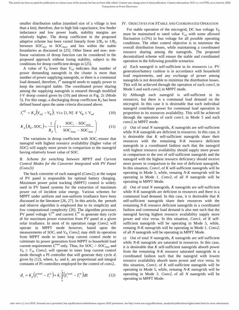
5) All nanogrids are above maximum threshold of SOC and
surplus PV power is available
To validate the scenario f of section IV, it is considered
that all the nanogrids are above maximum threshold and
surplus PV power is available due to high incident irradiance
(1000W/m2) i.e. SOCi > SOCmax ; ∀i=1, 2, 3, 4. Each naogrid
will tend to supply power to the DC bus based upon the
equation (6), therefore, its voltage will rise until it reaches to
VH. At VH, the proposed droop function given by (7), also
shown in Fig. 2c (Mode 4) will reduce the current supply to
zero and will try to keep the voltages fixed at VH. Since, the
batteries are already above maximum threshold, therefore,
any local PV generation PiPV
, higher than local household
requirements Piload
will overcharge the battery and cause DC
bus voltage to rise above the maximum limit VH, thus
instigating instability in the system. At this point, the control
schematic of conv2i changes its control from MPPT to inner
loop current control mode as shown in Fig. 2c. Therefore, I-
V droop control mode (constant droop coefficient Rd) of
Conv1i stabilizes the DC bus voltage at VH and Conv2i
ensures stability by culminating generation capability of each
nanogrid according to the load requirements at individual
household level. Fig. 7a shows that when DC bus voltage is
below maximum threshold VH, each nanogrid contributes for
current according to its SOCi. Once the voltage reaches to
VH, current contribution from each nanogrid becomes zero,
and further rise in voltage is restricted to VH. Before attaining
VH, each Conv2i is operating in MPPT mode, thus extracting
maximum power (500 W at incident irradiance of 1000
W/m2). However, once DC bus voltage attains its maximum
value VH, the PV generation is limited according to
household load requirements.
Fig. 7b. Power generated by PV panels in nanogrid 1 P1PV (righy Y-axis)
and output current I1in of conv21(left Y-axis) in case 5 (simulation
results)
Fig. 7a. DC bus voltage VB profile (righy Y-axis) and current sharing
among nanogrids (I1L, I2
L, I3L and I4
L) (left Y-axis) in case 5 (simulation
results)
0885-8993 (c) 2018 IEEE. Personal use is permitted, but republication/redistribution requires IEEE permission. See http://www.ieee.org/publications_standards/publications/rights/index.html for more information.
This article has been accepted for publication in a future issue of this journal, but has not been fully edited. Content may change prior to final publication. Citation information: DOI 10.1109/TPEL.2018.2828538, IEEETransactions on Power Electronics
This is shown in Fig. 7b, where Conv21 of nanogrid 1 is
working in MPPT (P&O) mode and generating power around
500W in the start of simulation. At t=0.027s, VB reaches to
its maximum allowable limit, therefore, Conv2i shifts is
control from MPPT to current control mode, therefore, the
output current of conv2i i.e. I1in
coincides with load current
I1PV
waveform as shown in Fig. 7b. This has been also shown
in Fig. 7c where, SOCi of each converter is increasing due to
PV generation higher than load requirements, when VB is
below VH. After VB becomes equal to VH, due to change in
control mode of Conv21 and associated limited PV
generation, the SOC of the battery does not rise any further
and becomes constant onwards.
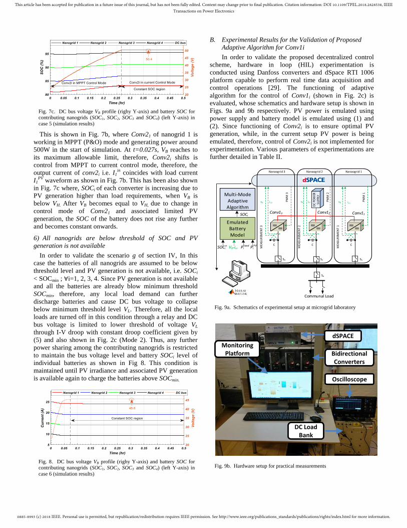
6) All nanogrids are below threshold of SOC and PV
generation is not available
In order to validate the scenario g of section IV, In this
case the batteries of all nanogrids are assumed to be below
threshold level and PV generation is not available, i.e. SOCi
< SOCmin ; ∀i=1, 2, 3, 4. Since PV generation is not available
and all the batteries are already blow minimum threshold
SOCmin, therefore, any local load demand can further
discharge batteries and cause DC bus voltage to collapse
below minimum threshold level VL. Therefore, all the local
loads are turned off in this condition through a relay and DC
bus voltage is limited to lower threshold of voltage VL
through I-V droop with constant droop coefficient given by
(5) and also shown in Fig. 2c (Mode 2). Thus, any further
power sharing among the contributing nanogrids is restricted
to maintain the bus voltage level and battery SOCi level of
individual batteries as shown in Fig 8. This condition is
maintained until PV irradiance and associated PV generation
is available again to charge the batteries above SOCmin.
B. Experimental Results for the Validation of Proposed
Adaptive Algorithm for Conv1i
In order to validate the proposed decentralized control
scheme, hardware in loop (HIL) experimentation is
conducted using Danfoss converters and dSpace RTI 1006
platform capable to perform real time data acquisition and
control operations [29]. The functioning of adaptive
algorithm for the control of Conv1i (shown in Fig. 2c) is
evaluated, whose schematics and hardware setup is shown in
Figs. 9a and 9b respectively. PV power is emulated using
power supply and battery model is emulated using (1) and
(2). Since functioning of Conv2i is to ensure optimal PV
generation, while, in the current setup PV power is being
emulated, therefore, control of Conv2i is not implemented for
experimentation. Various parameters of experimentations are
further detailed in Table II.
dSPACE
Bidirectional Converters
Monitoring Platform
Oscilloscope
DC Load Bank
Fig. 9b. Hardware setup for practical measurements
PWM
1
MEA
SUR
EMEN
T 1
MEA
SUR
EMEN
T 2
MEA
SUR
EMEN
T 3
S1
S4
DC
POW
ER
SUPP
LY
Communal Load
C
PWM
2
C
PWM
3
S3
C
Conv11Conv12Conv13
Nanaogrid 3 Nanaogrid 2 Nanaogrid 1
io1vBio2io3
S2
Multi-ModeAdaptive Algorithm
PiPVPi
loadVB*ioi
Emulated Battery Model
SOCio
vBvB
SOCi
Fig. 9a. Schematics of experimental setup at microgrid laboratory
Fig. 7c. DC bus voltage VB profile (righy Y-axis) and battery SOC for contributing nanogrids (SOC1, SOC2, SOC3 and SOC4) (left Y-axis) in
case 5 (simulation results)
Fig. 8. DC bus voltage VB profile (righy Y-axis) and battery SOC for contributing nanogrids (SOC1, SOC2, SOC3 and SOC4) (left Y-axis) in
case 6 (simulation results)

0885-8993 (c) 2018 IEEE. Personal use is permitted, but republication/redistribution requires IEEE permission. See http://www.ieee.org/publications_standards/publications/rights/index.html for more information.
This article has been accepted for publication in a future issue of this journal, but has not been fully edited. Content may change prior to final publication. Citation information: DOI 10.1109/TPEL.2018.2828538, IEEETransactions on Power Electronics
TABLE II
PARAMETERS OF EXPERIMENTAL CASE STUDY
Description of the Parameter Symbol Value Description of the Parameter Symbol Value
No. of Nanogrids/ households N 3 Maximum threshold of battery SOC SOCmax 80%
DC bus capacitance CB 3.3mF Minimum threshold of battery SOC SOCmin 30%
Inductance of each Conv1i L1 8.6H Reference voltage for DC bus Vref 48V
Stray resistance for Inductors ri 0.1Ω Initial Voltage of DC bus VB0 24V
Switching frequency for Conv1i fsw 10kHz Lower limit on DC bus voltage VL 45.6V
Rated power of each PV panel PPV 500Wp Higher limit on DC bus voltage VH 50.4V Rated household load Pload 200W Proportional and integral parameters (Conv1i) kp ,ki 0.02, 0.1
Battery capacity for each nanogrid C 2400Wh Droop Coefficient for Conv1i Rd 0.25Ω
Rated charging current for battery Irated 5A
1) All nanogrids are within specified thresholds of SOC
In this scenario, the batteries of all nanogrids are assumed
to be within specified thresholds of SOC i.e. SOCmin ≤ SOCi ≤
SOCmax ; ∀i=1,2, 3. This case is evaluated with and without
communal load of 135W and results for variations in bus
voltage, current sharing among contributing nanogrids and
accelerated simulations (1 hr) for SOCi are shown in Figs. 10a
and 10b respectively. Measured results are in accordance with
the simulation results as without communal load, the current
sharing among the contributing nanogrids is almost zero
(slightly higher than zero due to ESR of individual capacitors,
which otherwise was zero in case of simulation result due to
ideal capacitor). Upon application of communal load, the
current sharing is in proportional to SOCi value. For instance,
battery of nanogrid 1 with initial SOC10=35% is supplying
0.79 A, nanogrid 2 with initial SOC20=55% is supplying 1.05
A, and nanogrid 3 with initial SOC30=75% is supplying 1.33
A for communal load application.
The change in SOC is also in accordance with the SOC
availability i.e. ΔSOC1 = 0.49 %, ΔSOC2 = 0.66 % and ΔSOC3
= 0.84 %. Also the initial transition and transition from no
load to communal load scenario is fast and smooth as shown
in Figs. 10a and 10b respectively.
2) All nanogrids are within specified thresholds of SOC
except one which is above maximum threshold of SOC
In this scenario, the batteries of three nanogrids are
assumed to be within specified thresholds of SOC, while
battery of fourth nanogrid is above maximum threshold, i.e.
SOCmin ≤ SOCj ≤ SOCmax ; ∀i= 2, 3; SOC1 > SOCmax. Results
for bus voltage profile, current sharing among contributing
nanogrids and accelerated simulations (1 hour) for SOCi are
shown in Figs. 11a and 11b respectively. Results verify that
the nanogrid 1 having SOC higher than maximum threshold is
the supplying nanogrid while remaining two nanogrids
demand according to their resource availability.
Fig. 11b. DC bus voltage VB profile (righy Y-axis) and battery SOC for
contributing nanogrids (SOC1, SOC2, SOC3 and SOC4) (left Y-axis) in
case 2 (measured results)
Fig. 11a. DC bus voltage VB profile (righy Y-axis) and current sharing
among nanogrids (I1L, I2
Land I3L ) (left Y-axis) in case 2 (measured
results)
Fig. 10b. DC bus voltage VB profile (righy Y-axis) and battery SOC for
contributing nanogrids (SOC1, SOC2, SOC3 and SOC4) (left Y-axis) in
case 1 (measured results)
Fig. 10a. DC bus voltage VB profile (righy Y-axis) and current sharing
among nanogrids (I1L, I2
Land I3L ) (left Y-axis) in case 1 (measured
results)

0885-8993 (c) 2018 IEEE. Personal use is permitted, but republication/redistribution requires IEEE permission. See http://www.ieee.org/publications_standards/publications/rights/index.html for more information.
This article has been accepted for publication in a future issue of this journal, but has not been fully edited. Content may change prior to final publication. Citation information: DOI 10.1109/TPEL.2018.2828538, IEEETransactions on Power Electronics
12
Nanogrid 2 with higher value of initial SOC20=60% is
absorbing relatively lower current in comparison to nanogrid
3 having higher value of initial SOC20=40%. Therefore,
change in SOC for absorbing nanogrids from start till end of
the simulation is in accordance with resource availability i.e.
ΔSOC2 = 0.95% and ΔSOC3 = 1.2% with (ΔSOC3 > ΔSOC2).
3) Multi-mode switching of an individual Nanogrid
Nanogrids 2 and 3 are considered to be working within
specified maximum and minimum thresholds of SOC with
SOC2<SOC3 while, nanogrid 1 is considered below threshold
in the start of simulation. It is assumed that PV power
produced within nanogrids 2 and 3 is in accordance with their
household load, while PV power produced within nanogrid 1
is higher than its household load requirements. Therefore,
based upon the emulated model of battery, SOC1 will increase
from values below SOCmin to values above SOCmax, and
Conv11 will switch its operating modes accordingly.
Fig. 12 shows the variations in current sharing among
contributing nanogrids (I1L, I2
L, and I3
L) based upon the
accelerated SOC variations of an individual nanogrid (SOC1).
Accelerated SOC variations at nanogrid 1 are achieved by
considering reduced battery capacity (C/10). From Fig. 12, it
can be observed that for region SOC1 < SOCmin , nanogrid 1 is
demanding current with negative value of I1L and nanogrid 2
and 3 are supplying in proportion to their SOC, therefore,
battery of nanogrid 3 having initial SOC3(0)
=60% is supplying
more current in this region in comparison to nanogrid 2
having SOC2(0)
=40%. This is in accordance with the
simulation results shown in Fig. 6 and I-V droop function as
shown in Fig. 2c (Mode 5). The slope of droop increases with
SOC in this particular region as shown by the arrow in Fig.
12, which is in accordance with equation discharging droop
coefficient Kd(SOCi, Rd) given by (11). For intermediate
region, the current contribution from each nanogrid becomes
zero; therefore, it also validates our consideration of almost
zero distribution losses in the range of SOCmin ≤ SOC i≤
SOCmax. Finally, in the region when SOCi > SOCmax, nanogrid
1 start supplying current with positive value of I1L, while
nanogrid 2 and nanogrid 3 absorb power in proportion to their
resource deficiency. Current sharing is controlled by charging
droop coefficient Kc(SOCi, Rd) given by (9) and shown in
Fig. 2c (Mode 5), such that nanogrid 3 having SOC3(0)
= 60%
is absorbing less current in this region in comparison to
nanogrid 2 having SOC2(0)
=40%.
Fig. 12. Nanogrid 1 SOC1 variations in the various threshold ranges (left Y-axis) and associated current sharing among the contributing nanogrids (right
Y- axis) in case 3 (measured results).
VI. CONCLUSION
An adaptive I-V droop method for the decentralized
control of a PV/Battery-based distributed architecture of an
islanded DC microgrid is presented and its validity is
demonstrated with simulations and hardware in loop
experimentation. The stability of islanded microgrid in critical
operation conditions is ensured via controlled synchronization
between generation resources and load requirements. The
proposed control method is highly suitable for the rural
electrification of developing regions because it (i) enables
coordinated distribution of generation and storage resources
at a village scale, (ii) reduces distribution losses associated
with delivery of energy between generation and load end; (iii)
decentralized controllability omits the need of central
controller and associated costly communication infrastructure,
and (iv) enables resource sharing among the community to
extract the benefit of usage diversity at a village scale. Results
have also shown that adaptive I-V droop algorithm enables
fast and smooth transitions among various modes of
microgrid operation based upon the resource availability in
individual households of the village. Therefore, the
implementation of proposed control method on PV/battery
based DGDSA of islanded DC microgrid will enable high
efficiency and better resource utilization in future rural
electrification implementations.
REFERENCES
[1] World Energy Outlook (WEO, 2016), Electricity Access Database
[Online]. Available: http://www.worldenergyoutlook.org/resources/energydevelopment/ener
gyaccessdatabase/.
[2] K. Ubilla et al., "Smart microgrids as a solution for rural electrification: Ensuring long-term sustainability through cadastre and business
models," IEEE Transactions on Sustainable Energy, vol. 5, no. 4, pp.
1310-1318, 2014. [3] N. J. Williams, P. Jaramillo, J. Taneja, and T. S. Ustun, "Enabling
private sector investment in microgrid-based rural electrification in
developing countries: A review," Renewable and Sustainable Energy Reviews, vol. 52, pp. 1268-1281, 2015.
[4] S. C. Bhattacharyya, "Financing energy access and off-grid
electrification: A review of status, options and challenges," Renewable and Sustainable Energy Reviews, vol. 20, pp. 462-472, 2013.
[5] J. J. Justo, F. Mwasilu, J. Lee, and J.-W. Jung, "AC-microgrids versus
DC-microgrids with distributed energy resources: A review," Renewable and Sustainable Energy Reviews, vol. 24, pp. 387-405,
2013.
[6] J. Khan and M. H. Arsalan, "Solar power technologies for sustainable electricity generation–A review," Renewable and Sustainable Energy
Reviews, vol. 55, pp. 414-425, 2016.
[7] K. Shenai, A. Jhunjhunwala, and P. Kaur, "Electrifying India: Using solar dc microgrids," IEEE Power Electronics Magazine, vol. 3, no. 4,
pp. 42-48, 2016.
[8] P. A. Madduri, J. Poon, J. Rosa, M. Podolsky, E. A. Brewer, and S. R. Sanders, "Scalable DC Microgrids for Rural Electrification in Emerging
Regions," IEEE Journal of Emerging and Selected Topics in Power
Electronics, vol. 4, no. 4, pp. 1195-1205, 2016. [9] S. Mishra and O. Ray, "Advances in nanogrid technology and its
integration into rural electrification in India," in Power Electronics
Conference (IPEC-Hiroshima 2014-ECCE-ASIA), 2014 International, 2014, pp. 2707-2713: IEEE.
[10] D. Palit, G. K. Sarangi, and P. Krithika, "Energising Rural India Using
Distributed Generation: The Case of Solar Mini-Grids in Chhattisgarh State, India," in Mini-Grids for Rural Electrification of Developing
Countries: Springer, 2014, pp. 313-342.
[11] D. Palit and G. K. Sarangi, "Renewable energy based mini-grids for enhancing electricity access: Experiences and lessons from India," in

0885-8993 (c) 2018 IEEE. Personal use is permitted, but republication/redistribution requires IEEE permission. See http://www.ieee.org/publications_standards/publications/rights/index.html for more information.
This article has been accepted for publication in a future issue of this journal, but has not been fully edited. Content may change prior to final publication. Citation information: DOI 10.1109/TPEL.2018.2828538, IEEETransactions on Power Electronics
13
International Conference and Utility Exhibition on Green Energy for
Sustainable Development (ICUE),\ 19-21 March 2014, pp. 1-8.
[12] J. Urpelainen, "Energy poverty and perceptions of solar power in
marginalized communities: Survey evidence from Uttar Pradesh, India,"
Renewable Energy, vol. 85, pp. 534-539, 2016. [13] M. Nasir, N. A. Zaffar, and H. A. Khan, "Analysis on central and
distributed architectures of solar powered DC microgrids," in 2016
Clemson University Power Systems Conference (PSC), 2016, pp. 1-6. [14] S. Groh, D. Philipp, B. E. Lasch, and H. Kirchhoff, "Swarm
electrification-Suggesting a paradigm change through building
microgrids bottom-up," in Developments in Renewable Energy Technology (ICDRET), 2014 3rd International Conference on the,
2014, pp. 1-2: IEEE.
[15] W. Inam, D. Strawser, K. K. Afridi, R. J. Ram, and D. J. Perreault, "Architecture and system analysis of microgrids with peer-to-peer
electricity sharing to create a marketplace which enables energy
access," in Power Electronics and ECCE Asia (ICPE-ECCE Asia), 2015 9th International Conference on, 2015, pp. 464-469: IEEE.
[16] P. A. Madduri, J. Rosa, S. R. Sanders, E. A. Brewer, and M. Podolsky,
"Design and verification of smart and scalable DC microgrids for emerging regions," in Energy Conversion Congress and Exposition
(ECCE), 2013 IEEE, 2013, pp. 73-79: IEEE.
[17] P. A. Madduri, J. Poon, J. Rosa, M. Podolsky, E. Brewer, and S. R. Sanders, "Scalable DC Microgrids for Rural Electrification in Emerging
Regions," IEEE Journal of Emerging and Selected Topics in Power
Electronics, vol. PP, no. 99, pp. 1-1, 2016. [18] J. Chi, W. Peng, X. Jianfang, T. Yi, and C. Fook Hoong,
"Implementation of Hierarchical Control in DC Microgrids," Industrial Electronics, IEEE Transactions on, vol. 61, no. 8, pp. 4032-4042, 2014.
[19] T. Dragičević, J. M. Guerrero, J. C. Vasquez, and D. Škrlec,
"Supervisory control of an adaptive-droop regulated DC microgrid with battery management capability," IEEE Transactions on Power
Electronics, vol. 29, no. 2, pp. 695-706, 2014.
[20] Q. Shafiee, T. Dragičević, J. C. Vasquez, and J. M. Guerrero, "Hierarchical control for multiple DC-microgrids clusters," IEEE
Transactions on Energy Conversion, vol. 29, no. 4, pp. 922-933, 2014.
[21] J. M. Guerrero, J. C. Vasquez, J. Matas, L. G. De Vicuña, and M. Castilla, "Hierarchical control of droop-controlled AC and DC
microgrids—A general approach toward standardization," IEEE
Transactions on Industrial Electronics, vol. 58, no. 1, pp. 158-172, 2011.
[22] M. Nasir, H. A. Khan, A. Hussain, L. Mateen, and N. A. Zaffar, "Solar
PV-Based Scalable DC Microgrid for Rural Electrification in Developing Regions," IEEE Transactions on Sustainable Energy, vol.
9, no. 1, pp. 390-399, 2018.
[23] X. Lu, K. Sun, J. M. Guerrero, J. C. Vasquez, and L. Huang, "State-of-charge balance using adaptive droop control for distributed energy
storage systems in DC microgrid applications," IEEE Transactions on
Industrial Electronics, vol. 61, no. 6, pp. 2804-2815, 2014. [24] Z. Jin, L. Meng, and J. M. Guerrero, "Comparative admittance-based
analysis for different droop control approaches in DC microgrids," in
DC Microgrids (ICDCM), 2017 IEEE Second International Conference
on, 2017, pp. 515-522: IEEE.
[25] F. Gao et al., "Comparative stability analysis of droop control
approaches in voltage-source-converter-based DC microgrids," IEEE Transactions on Power Electronics, vol. 32, no. 3, pp. 2395-2415,
2017.
[26] B. Subudhi and R. Pradhan, "A comparative study on maximum power point tracking techniques for photovoltaic power systems," Sustainable
Energy, IEEE transactions on, vol. 4, no. 1, pp. 89-98, 2013.
[27] M. Nasir and M. F. Zia, "Global maximum power point tracking algorithm for photovoltaic systems under partial shading conditions," in
Power Electronics and Motion Control Conference and Exposition
(PEMC), 2014 16th International, 2014, pp. 667-672. [28] M. Nasir, S. Iqbal, and H. A. Khan, "Optimal Planning and Design of
Low-Voltage Low-Power Solar DC Microgrids," IEEE Transactions on
Power Systems, 2017. [29] L. Meng, M. Savaghebi, F. Andrade, J. C. Vasquez, J. M. Guerrero, and
M. Graells, "Microgrid central controller development and hierarchical
control implementation in the intelligent microgrid lab of Aalborg University," in Applied Power Electronics Conference and Exposition
(APEC), 2015 IEEE, 2015, pp. 2585-2592: IEEE.
Mashood Nasir received his BS degree in
Electrical Engineering from UET Lahore,
Pakistan and MS in Electrical Engineering from
UMT Lahore, Pakistan in 2009 and 2011
respectively. From 2011 to 2012, he served as a lecturer and from 2013-2014 he served as an
assistant professor in Electrical Engineering
department at UMT, Lahore. From, May 2017 to Nov 2017 he was a visiting PhD researcher at the
Microgrid Laboratory in Aalborg University
Denmark. Currently, he is a PhD candidate in department of electrical Engineering at LUMS. His research interests mainly
include but not limited to power electronics, electrical machines and drives,
grid integration of alternate energy resources, electrochemical energy conversion and battery storage systems and AC/DC/Hybrid microgrids.
Zheming Jin (S’15) received the B.S. degree in electrical engineering and the M.S. degree in
power electronics and ac drives from Beijing
Jiaotong University, Beijing, China, in 2013 and 2015, respectively. He is currently working
toward the Ph.D. degree in power electronic
systems with the Department of Energy Technology, Aalborg University, Aalborg,
Denmark. His research interests include control
of power electronic converters, stability of power electronic systems, energy storage, dc microgrids,
and their applications in transportation electrification.
Dr. Khan received the B.Eng degree in electronic
engineering from GIKI, Pakistan in 2005. From
2005 to 2010, he was with School of Electrical Engineering, The University of Manchester, UK
where he first received his MSc (with distinction)
and then PhD in electrical and electronic
engineering. He is currently serving as assistant
professor in the department of Electrical
Engineering at LUMS. His current research is on renewable energy and its uptake in developing
countries. His core focus is on novel grid
architectures for low-cost rural electrification through solar energy. He is also working on efficient and reliable solar PV deployments in urban settings to
maximize their performance ratios.
Prof. Nauman Ahmad Zaffar currently serves as
Associate Professor and Director of Energy and
Power Systems Research Cluster at Department of Electrical Engineering, SBASSE, LUMS,
Lahore, Pakistan. His areas of research include
smart grids and power electronic converters for integration of renewable energy resources and
motor loads with an increasingly smarter grid.
His primary research focus is on harnessing and
efficient utilization of energy from available
sources such as solar PV, solar thermal, wind and hydrokinetics to enable energy independent, integrated, smart grid
communities. He has been actively engaged in arranging and delivering
national workshops in core areas of circuits, electronics, power electronics and design of magnetics
Juan C. Vasquez (M’12-SM’14) received the B.S. degree in electronics engineering from the
Autonomous University of Manizales,
Manizales, Colombia, and the Ph.D. degree in automatic control, robotics, and computer
vision from the Technical University of
Catalonia, Barcelona, Spain, in 2004 and 2009, respectively. He was with the Autonomous
University of Manizales working as a teaching
assistant and the Technical University of Catalonia as a Post-Doctoral Assistant in 2005
and 2008 respectively. In 2011, he was Assistant Professor and from 2014 he
is working as an Associate Professor at the Department of Energy Technology, Aalborg University, Denmark where he is the Vice Program

0885-8993 (c) 2018 IEEE. Personal use is permitted, but republication/redistribution requires IEEE permission. See http://www.ieee.org/publications_standards/publications/rights/index.html for more information.
This article has been accepted for publication in a future issue of this journal, but has not been fully edited. Content may change prior to final publication. Citation information: DOI 10.1109/TPEL.2018.2828538, IEEETransactions on Power Electronics
14
Leader of the Microgrids Research Program (see microgrids.et.aau.dk). From
Feb. 2015 to April 2015 he was a Visiting Scholar at the Center of Power
Electronics Systems (CPES) at Virginia Tech and a visiting professor at
Ritsumeikan University, Japan. His current research interests include
operation, advanced hierarchical and cooperative control, optimization and energy management applied to distributed generation in AC/DC Microgrids,
maritime microgrids, advanced metering infrastructures and the integration of
Internet of Things and Cyber-Physical Systems into the Smart Grid. He has authored and co-authored more than 100 technical papers only in Microgrids
in international IEEE conferences and journals.
Josep M. Guerrero (S’01–M’04–SM’08–
FM’15) received the B.S. degree in
telecommunications engineering, the M.S. degree in electronics engineering, and the
Ph.D. degree in power electronics from the
Technical University of Catalonia, Barcelona, Spain, in 1997, 2000, and 2003, respectively.
Since 2011, he has been a Full Professor in the
Department of Energy Technology, Aalborg University, Aalborg, Denmark, where he is
responsible for the Microgrid Research
Program. Since 2012, he has been a Guest Professor at the Chinese Academy of Science, Beijing, China and the Nanjing University of Aeronautics and
Astronautics, Nanjing, China; since 2014, he has been the Chair Professor in
Shandong University, Jinan, China; since 2015, he has been a Distinguished Guest Professor in Hunan University, Changsha, China; and since 2016, he
has been a visiting Professor Fellow in Aston University, Birmingham, U.K. His research interest is oriented to different microgrid aspects, including
power electronics, distributed energy-storage systems, hierarchical and
cooperative control, energy management systems, smart metering and the Internet of things for ac/dc microgrid clusters and islanded minigrids; current
research interest especially focused on maritime microgrids for electrical
ships, vessels, ferries, and seaports. Prof. Guerrero is an Associate Editor of the IEEE TRANSACTIONS ON POWER ELECTRONICS, the IEEE
TRANSACTIONS ON INDUSTRIAL ELECTRONICS, and the IEEE
INDUSTRIAL ELECTRONICS MAGAZINE, and an Editor of the IEEE TRANSACTIONS ON SMART GRID and the IEEE TRANSACTIONS ON
ENERGY CONVERSION. He was the Chair of the Renewable Energy
Systems Technical Committee of the IEEE Industrial Electronics Society. He received the IEEE TRANSACTIONS ON ENERGY CONVERSION Best
Paper Award for the period 2014–2015. In 2014 and 2015, he received the
Highly Cited Researcher Award by Thomson Reuters, and in 2015, he was elevated as the IEEE Fellow.


![Aalborg Universitet A Decentralized Control …...Wardah et al. [15] presented a partially distributed architecture, in which peer to peer electricity sharing was enabled by GSM based](https://img.pdfslide.us/doc/110x75/5e5bad0bae36fa5767727a98/aalborg-universitet-a-decentralized-control-wardah-et-al-15-presented-a-partially.jpg)