Embed Size (px)
Citation preview
11© Crown copyright 2016
AAIB Bulletin: 10/2016 G-BYCP EW/C2015/10/01
ACCIDENT
Aircraft Type and Registration: Beech B200 Super King Air, G-BYCP
No & Type of Engines: 2 Pratt & Whitney Canada PT6A-42 turboprop engines
Year of Manufacture: 1981 (Serial no: BB-966)
Date & Time (UTC): 3 October 2015 at 0920 hrs
Location: Near Chigwell, Essex
Type of Flight: Non-commercial
Persons on Board: Crew - 1 Passengers - 1
Injuries: Crew - 1 (Fatal) Passengers - 1 (Fatal)
Nature of Damage: Aircraft destroyed
Commander’s Licence: Commercial Pilot’s Licence
Commander’s Age: 40 years
Commander’s Flying Experience: 1,941 hours (of which 162 hours were on type) Last 90 days - 61 hours Last 28 days - 50 hours
Information Source: AAIB Field Investigation
Synopsis
The aircraft was climbing through approximately 750 ft amsl after takeoff when it began to turn right. It continued to climb in the turn until it reached approximately 875 ft amsl when it began to descend. The descent continued until the aircraft struck some trees at the edge of a field, approximately 1.8 nm southwest of the aerodrome. The evidence available was consistent with a loss of aircraft control in Instrument Meteorological Conditions (IMC), but this could not be concluded unequivocally because of a lack of evidence from within the cockpit. However, it is possible the pilot became incapacitated and the additional crew member was unable to recover the aircraft in the height available.
Three Safety Recommendations are made regarding the fitment of Terrain Awareness and Warning Systems (TAWS).
History of the flight
G‑BYCP was planned to operate a non‑commercial flight from Stapleford Aerodrome to RAF Brize Norton with two company employees on board (including the pilot) to pick up two passengers for onward travel. The pilot (the aircraft commander) held a Commercial Pilot’s Licence (CPL) and occupied the left seat and another pilot, who held an Airline Transport Pilot’s Licence (ATPL), occupied the right. The second occupant worked for the operator of G-BYCP but his licence was valid on Bombardier Challenger 300 and Embraer ERJ 135/145 aircraft and not on the King Air.
12© Crown copyright 2016
AAIB Bulletin: 10/2016 G-BYCP EW/C2015/10/01
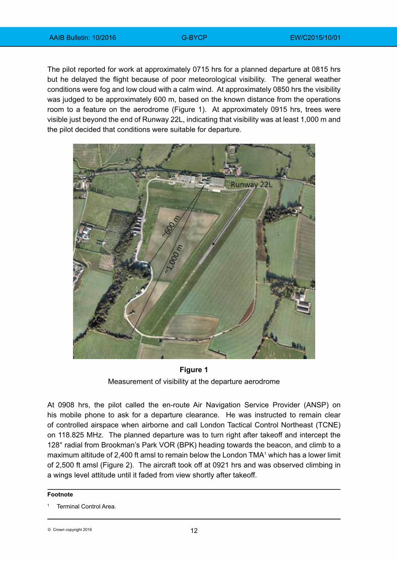
The pilot reported for work at approximately 0715 hrs for a planned departure at 0815 hrs but he delayed the flight because of poor meteorological visibility. The general weather conditions were fog and low cloud with a calm wind. At approximately 0850 hrs the visibility was judged to be approximately 600 m, based on the known distance from the operations room to a feature on the aerodrome (Figure 1). At approximately 0915 hrs, trees were visible just beyond the end of Runway 22L, indicating that visibility was at least 1,000 m and the pilot decided that conditions were suitable for departure.
Figure 1Measurement of visibility at the departure aerodrome
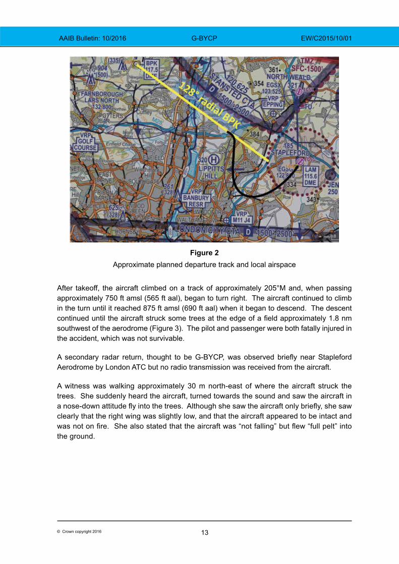
At 0908 hrs, the pilot called the en-route Air Navigation Service Provider (ANSP) on his mobile phone to ask for a departure clearance. He was instructed to remain clear of controlled airspace when airborne and call London Tactical Control Northeast (TCNE) on 118.825 MHz. The planned departure was to turn right after takeoff and intercept the 128° radial from Brookman’s Park VOR (BPK) heading towards the beacon, and climb to a maximum altitude of 2,400 ft amsl to remain below the London TMA1 which has a lower limit of 2,500 ft amsl (Figure 2). The aircraft took off at 0921 hrs and was observed climbing in a wings level attitude until it faded from view shortly after takeoff.
Footnote1 Terminal Control Area.
13© Crown copyright 2016
AAIB Bulletin: 10/2016 G-BYCP EW/C2015/10/01
Figure 2
Approximate planned departure track and local airspace
After takeoff, the aircraft climbed on a track of approximately 205°M and, when passing approximately 750 ft amsl (565 ft aal), began to turn right. The aircraft continued to climb in the turn until it reached 875 ft amsl (690 ft aal) when it began to descend. The descent continued until the aircraft struck some trees at the edge of a field approximately 1.8 nm southwest of the aerodrome (Figure 3). The pilot and passenger were both fatally injured in the accident, which was not survivable.
A secondary radar return, thought to be G‑BYCP, was observed briefly near Stapleford Aerodrome by London ATC but no radio transmission was received from the aircraft.
A witness was walking approximately 30 m north-east of where the aircraft struck the trees. She suddenly heard the aircraft, turned towards the sound and saw the aircraft in a nose‑down attitude fly into the trees. Although she saw the aircraft only briefly, she saw clearly that the right wing was slightly low, and that the aircraft appeared to be intact and was not on fire. She also stated that the aircraft was “not falling” but flew “full pelt” into the ground.
14© Crown copyright 2016
AAIB Bulletin: 10/2016 G-BYCP EW/C2015/10/01
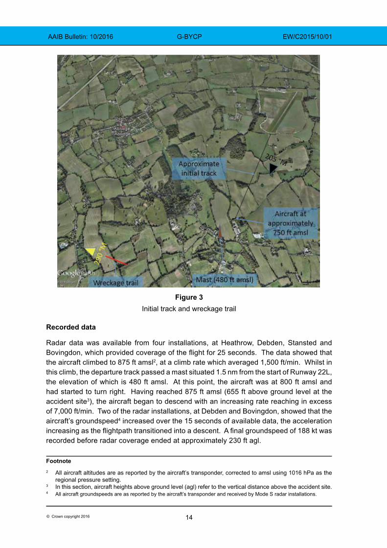
Figure 3
Initial track and wreckage trail
Recorded data
Radar data was available from four installations, at Heathrow, Debden, Stansted and Bovingdon, which provided coverage of the flight for 25 seconds. The data showed that the aircraft climbed to 875 ft amsl2, at a climb rate which averaged 1,500 ft/min. Whilst in this climb, the departure track passed a mast situated 1.5 nm from the start of Runway 22L, the elevation of which is 480 ft amsl. At this point, the aircraft was at 800 ft amsl and had started to turn right. Having reached 875 ft amsl (655 ft above ground level at the accident site3), the aircraft began to descend with an increasing rate reaching in excess of 7,000 ft/min. Two of the radar installations, at Debden and Bovingdon, showed that the aircraft’s groundspeed4 increased over the 15 seconds of available data, the acceleration increasing as the flightpath transitioned into a descent. A final groundspeed of 188 kt was recorded before radar coverage ended at approximately 230 ft agl.
Footnote2 All aircraft altitudes are as reported by the aircraft’s transponder, corrected to amsl using 1016 hPa as the
regional pressure setting.3 In this section, aircraft heights above ground level (agl) refer to the vertical distance above the accident site.4 All aircraft groundspeeds are as reported by the aircraft’s transponder and received by Mode S radar installations.
15© Crown copyright 2016
AAIB Bulletin: 10/2016 G-BYCP EW/C2015/10/01
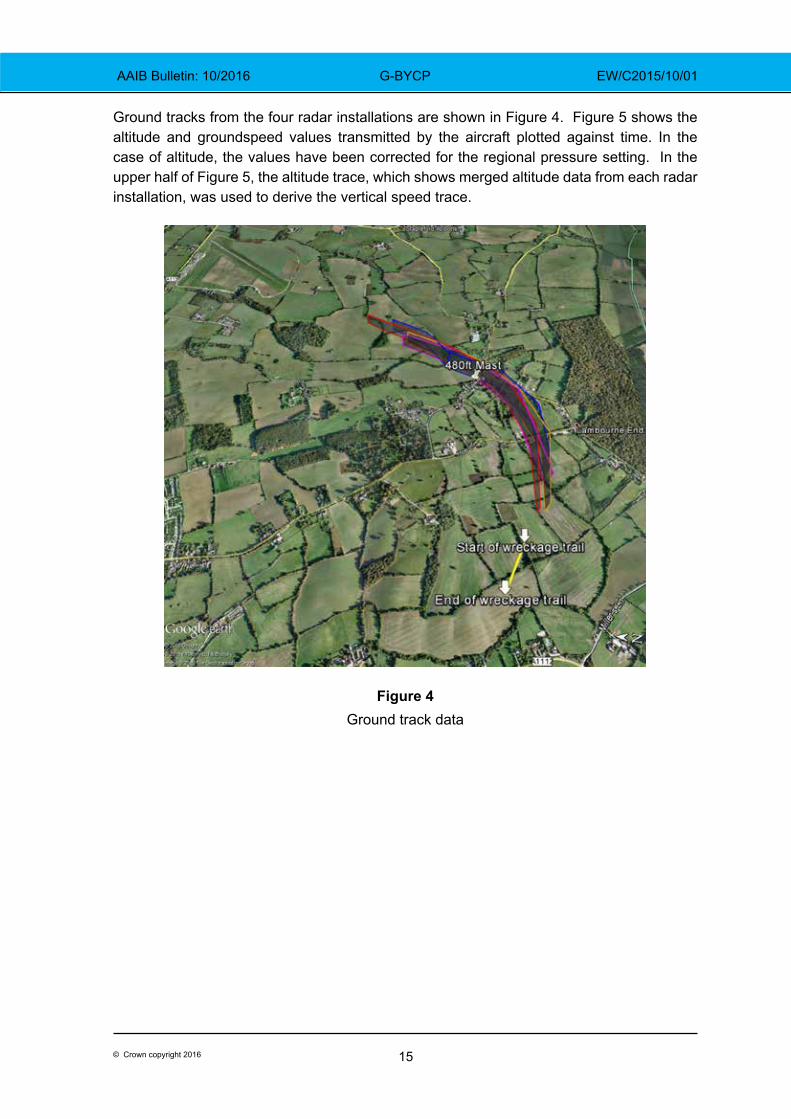
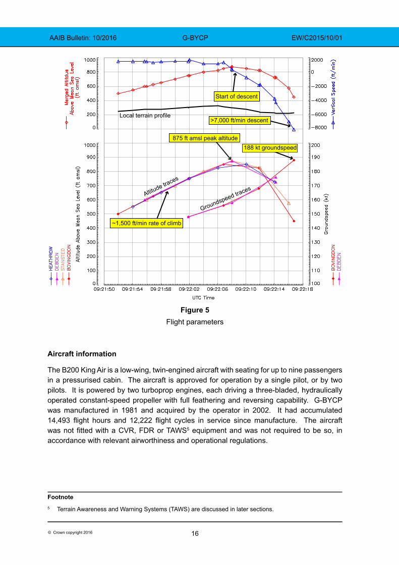
Ground tracks from the four radar installations are shown in Figure 4. Figure 5 shows the altitude and groundspeed values transmitted by the aircraft plotted against time. In the case of altitude, the values have been corrected for the regional pressure setting. In the upper half of Figure 5, the altitude trace, which shows merged altitude data from each radar installation, was used to derive the vertical speed trace.
Figure 4Ground track data
16© Crown copyright 2016
AAIB Bulletin: 10/2016 G-BYCP EW/C2015/10/01
875 ft amsl peak altitude
~1,500 ft/min rate of climb
Start of descent
Local terrain profile
Altitude traces
188 kt groundspeed
Groundspeed traces
>7,000 ft/min descent
Figure 5Flight parameters
Aircraft information
The B200 King Air is a low-wing, twin-engined aircraft with seating for up to nine passengers in a pressurised cabin. The aircraft is approved for operation by a single pilot, or by two pilots. It is powered by two turboprop engines, each driving a three-bladed, hydraulically operated constant-speed propeller with full feathering and reversing capability. G-BYCP was manufactured in 1981 and acquired by the operator in 2002. It had accumulated 14,493 flight hours and 12,222 flight cycles in service since manufacture. The aircraft was not fitted with a CVR, FDR or TAWS5 equipment and was not required to be so, in accordance with relevant airworthiness and operational regulations.
Footnote5 Terrain Awareness and Warning Systems (TAWS) are discussed in later sections.
17© Crown copyright 2016
AAIB Bulletin: 10/2016 G-BYCP EW/C2015/10/01
Accident site
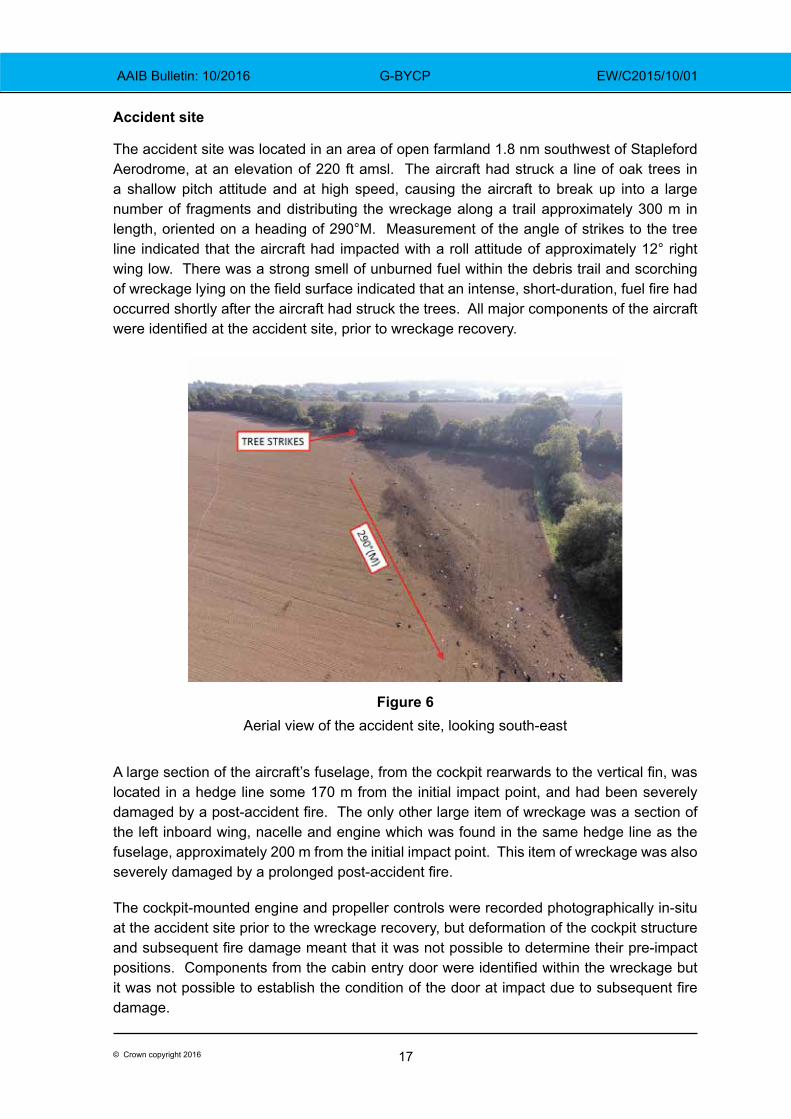
The accident site was located in an area of open farmland 1.8 nm southwest of Stapleford Aerodrome, at an elevation of 220 ft amsl. The aircraft had struck a line of oak trees in a shallow pitch attitude and at high speed, causing the aircraft to break up into a large number of fragments and distributing the wreckage along a trail approximately 300 m in length, oriented on a heading of 290°M. Measurement of the angle of strikes to the tree line indicated that the aircraft had impacted with a roll attitude of approximately 12° right wing low. There was a strong smell of unburned fuel within the debris trail and scorching of wreckage lying on the field surface indicated that an intense, short‑duration, fuel fire had occurred shortly after the aircraft had struck the trees. All major components of the aircraft were identified at the accident site, prior to wreckage recovery.
Figure 6
Aerial view of the accident site, looking south-east
A large section of the aircraft’s fuselage, from the cockpit rearwards to the vertical fin, was located in a hedge line some 170 m from the initial impact point, and had been severely damaged by a post‑accident fire. The only other large item of wreckage was a section of the left inboard wing, nacelle and engine which was found in the same hedge line as the fuselage, approximately 200 m from the initial impact point. This item of wreckage was also severely damaged by a prolonged post‑accident fire.
The cockpit-mounted engine and propeller controls were recorded photographically in-situ at the accident site prior to the wreckage recovery, but deformation of the cockpit structure and subsequent fire damage meant that it was not possible to determine their pre‑impact positions. Components from the cabin entry door were identified within the wreckage but it was not possible to establish the condition of the door at impact due to subsequent fire damage.
18© Crown copyright 2016
AAIB Bulletin: 10/2016 G-BYCP EW/C2015/10/01
The right engine had been released from the aircraft at the initial impact with the trees and had subsequently broken apart. Both the left and right propellers had detached from their respective engines during the accident and were found lying on the field surface.
The left propeller had detached forward of the hub mounting flange and all three blades remained attached to the hub; the blades were bent backwards and the propeller tips had detached.
The right propeller remained attached to the right engine reduction gearbox, which had separated from the right engine. Two of the right propeller’s blades remained attached to the hub and these blades were bent, one forwards and one backwards, and the tips had detached. The third blade had broken off at the root end and was located within the debris field. This blade was bent backwards and the tip had detached.
Wreckage examination
The wreckage was recovered to the AAIB’s facility at Farnborough. The high degree of fragmentation and fire damage to the aircraft’s structure and systems prevented a complete evaluation but that which remained was subject to a detailed and prolonged examination.
Engines
Both engines were dismantled and inspected with the assistance of a technical specialist from the engine manufacturer. No evidence of a pre-impact failure was found and internal witness marks, caused by contact between the engine’s rotating and static components during the accident, were consistent with both engines producing medium to high power at the moment of impact. There were no conditions observed of any of the engine components examined that would have precluded normal engine operation prior to impact.
Propellers
The aircraft’s propellers were examined with the assistance of a technical specialist from the propeller manufacturer. Both propellers exhibited significant blade bending and tip fractures consistent with rotation under power at or near rated6 rpm at impact. There were no discrepancies noted that would prevent or degrade normal operation prior to impact, and all observed damage was consistent with high impact forces.
Flying controls
The aircraft wreckage was examined with the assistance of a technical specialist from the aircraft manufacturer. Detailed examination of the aircraft’s primary flying control systems, from the cockpit mounted yoke and rudder pedal control assemblies out to the respective flying control surfaces, did not reveal any evidence of a pre‑accident flying control system failure. It was, however, not possible to eliminate the possibility of a pre-accident control restriction or jam due to the impact-related disruption of the aircraft’s
Footnote6 The B200’s PT6A-42 engines feature a propeller control system that governs the propellers to 2,000 rpm
during flight.
19© Crown copyright 2016
AAIB Bulletin: 10/2016 G-BYCP EW/C2015/10/01
structure. All observed discontinuities in the primary flying controls were attributable to tensile or bending overload, or to cuts made during the wreckage recovery.
The control surface trim actuators were examined, but due to the nature of the aircraft break-up and the fact that the trim systems were cable operated, it was not possible to determine accurately their positions at the moment of impact.
Flap system
The flaps, two on each wing, are driven by an electric motor through a gearbox mounted on the wing rear spar at the fuselage centreline. The gearbox drives four flexible drive cables that are connected to a jackscrew actuator at each flap. A safety mechanism, consisting of a torque tube, cam and microswitch, is provided for each pair of flaps to disconnect power to the electric motor in the event of a failure that causes any flap to be approximately 3°‑ 6° in misalignment with its adjacent flap.
Components from the aircraft’s flap drive system were recovered and examined in detail. Three of the four flap jackscrews were found to be in the flap retracted position whereas the fourth jackscrew, established by part number as the left inboard flap actuator, was found in the fully extended 100% (35°) position. The left inboard flexible flap drive cable, from the flap motor gearbox outboard, was examined, apart from a missing section approximately 8 cm in length from the outboard end which was not recovered. No mechanical defect or failure was found in the flap drive cable, or of the left inboard jackscrew itself, that could account for the difference in position to the other three flap jackscrews. Remnants of the left and right asymmetric flap protection system components were recovered from the wreckage but they were too badly damaged by fire to draw any conclusions about their pre‑accident condition.
The cockpit flap position indicator, which is driven by the position of the right inboard flap, showed that the needle was pointing to a position consistent with electrical power switched off, or removed, during the aircraft break‑up sequence.
Landing gear
The extensions of the landing gear mechanical actuators for all three landing gear legs were consistent with the landing gear being retracted at the point of impact.
Instruments
The captain’s primary and standby attitude indicators were recovered from the debris field and examined. The primary attitude indicator had sustained damage, preventing electrical or functional testing. Conclusions on the pitch and roll attitude displayed at impact were based solely on a physical examination performed at the manufacturer’s overhaul facility, under supervision of the AAIB. The gyro and gs (glideslope) flags were found in their retracted positions, and the flight director command bars were not fully retracted up; these three findings indicated that the attitude indicator was electrically powered at impact and that no fault had occurred that would have caused the gyro fail flag to display. The roll index gear, which rotates the instrument’s roll indicator pointer to present roll attitude, was pinned in four places around the gear due to impact forces, with a 12° right roll attitude displayed.
20© Crown copyright 2016
AAIB Bulletin: 10/2016 G-BYCP EW/C2015/10/01
Analysis of debris puncture marks through the Mylar pitch attitude tape showed that the pitch attitude displayed at impact was approximately -5° to -9° (nose down). Each of these pitch and roll readings was consistent with the tree strikes and wreckage distribution noted at the accident site.
The captain’s standby attitude indicator was examined, but the degree of damage sustained in the accident prevented its functional testing or an assessment of the pitch and roll reading at impact. There were clear signs of scoring on the surface of the instrument’s gyro rotor, indicating that the gyro was turning at high speed at impact. The attitude indicator’s off flag was relatively un-deformed, indicating that it was probably not deployed at impact.
Components from the co‑pilot’s air‑driven attitude indicator were identified in the wreckage but the degree of fragmentation of this instrument prevented an assessment of the attitude it displayed at impact.
Warning lamps
Fourteen lamp bulb units from various cockpit annunciator panels were recovered in a sufficiently intact condition to permit examination of their bulb filaments for evidence of ‘hot stretch’, which can indicate if a bulb was lit at impact. Examination of these recovered light bulbs showed that two annunciators were probably lit at impact; the amber msg and green nav annunciators from the panel above the primary attitude indicator. The msg annunciator was alerting the pilot to a message being displayed on one of the GNS430W GPS units fitted to the aircraft but no evidence was available to indicate what message was being displayed. The nav annunciator indicated that the GPS was operating in VOR mode.
Maintenance
The aircraft’s last scheduled maintenance inspection7 was carried out on 12 June 2015 at 14,289.5 hours and 12,049 flight cycles. The aircraft’s Airworthiness Review Certificate was renewed on 21 January 2015 and was valid at the time of the accident. The aircraft’s technical records were examined which showed that all life-limited components installed were within their permitted service lives at the time of the accident, and all Airworthiness Directives applicable to the aircraft had been complied with.
Technical Log entriesThe aircraft’s technical log was examined and contained no deferred defects prior to the accident flight. During the course of the investigation the AAIB became aware of a post‑flight ‘Engineering Report’ email reporting system used by the operator to permit flight crew to communicate operational information to the operator. The ‘Engineering Report’ emails also contained aircraft technical defects that were not recorded in the aircraft technical log or aircraft maintenance records.
Footnote7 This inspection was a ‘Phase 1’ inspection, one of a number of periodic inspections required by the aircraft’s
Approved Maintenance Programme.
21© Crown copyright 2016
AAIB Bulletin: 10/2016 G-BYCP EW/C2015/10/01
The aircraft was subject to maintenance regulations as defined in EASA Part M. Part M regulation M.A.403 refers to the recording of aircraft defects:
The post‑flight ‘Engineering Report’ emails for the nine months preceding the accident were reviewed. A total of 57 defects were recorded in this period that either met the definition of M.A.403(a), or were subject to a rectification interval specified in the B200 Minimum Equipment List (MEL) as required by M.A.403(c). None of these defects were recorded in the aircraft technical log, or the aircraft maintenance records, as required by M.A.403(d). Many of the defects were repeat reports over a series of flights and related to items including inoperative fuel gauges, failed autopilot mode annunciator lights, autopilot faults, inaccurate engine oil pressure and rpm indications, reports of the left engine being slow to accelerate, and a missing stall warning strip. There were no defects reported regarding the aircraft’s flying controls or flap system.
Aircraft maintenance records documenting the Phase 1 inspection carried out on 12 June 2015 referred to four ‘Customer reported defects’ that had been recorded in the ‘Engineering Report’ emails, but not in the technical log or aircraft maintenance records. Rectification of three of the four defects required replacement of defective components with newly overhauled parts. The B200 King Air MEL classifies one of the defects as Category B, requiring rectification within three calendar days of discovery, and the remaining three defects as Category C, requiring rectification within ten days of discovery. A review of the ‘Engineering Report’ emails showed that the Category B defect had been reported 31 days prior to rectification, and the three Category C defects had been reported 156 days prior to rectification.
In the week preceding the accident flight however, the aircraft had performed six flights and the email reporting system did not contain any significant defects apart from a worn main landing gear tyre. This was correctly recorded in the technical log and the tyre was replaced prior to the next flight.
22© Crown copyright 2016
AAIB Bulletin: 10/2016 G-BYCP EW/C2015/10/01
Information provided by the aircraft manufacturer
The aircraft manufacturer confirmed that during type certification flight testing, the B200 had been tested with the right outboard flap fully down at 100% (35°), whilst the other three flaps were fully retracted. In this condition, which is more severe than if just the right inboard flap had been fully deflected, a 27.5 lb control wheel force and 35% aileron deflection were sufficient to maintain lateral control. Aileron trim was sufficient to cancel all out‑of‑balance rolling moments and full stalls in this configuration were satisfactory.
The aircraft manufacturer also undertook flight performance analysis, based on the accident flight path recorded by secondary radar. The performance analysis included the effects of aircraft mass, aerodynamic drag and engine thrust. The analysis showed that, in order to achieve the recorded flight path, both engines were required to be operating at medium to high power. It was not possible to make any definitive findings regarding the engine power developed at the end of the radar coverage, as the aircraft descended below 600 ft amsl.
Pilot information
The pilot had flown 1,941 hours prior to the accident flight of which 1,791 hours were flown in single-engine piston aircraft. He gained a Multi-Engine Piston (MEP) Instrument Rating8 in October 2009 and was an examiner for the Instrument Meteorological Conditions (IMC) Rating. He obtained his King Air type rating9 on 17 June 2014 and, in the following 12 months, flew with two operators before being employed by the operator of G‑BYCP.
The pilot renewed his King Air type rating on 23 May 2015 and flew approximately 67 hours in the right seat of the operator’s King Air aircraft to familiarise himself with the way they were operated. He began his line training with the operator of G-BYCP on 16 August 2015 and passed his line check on 27 September 2015. The operator reported that the weather was generally good during the pilot’s line training and he had not been required to fly an IMC departure from Stapleford Aerodrome.
At the time of the accident the pilot had flown 162 hours 15 minutes on type including 6 hours 40 minutes flown as the aircraft commander and 113 hours 5 minutes flown as pilot in command under the supervision of the aircraft commander.
Medical and pathological information
The pilot
The pilot held a Class 1 medical certificate valid until 17 December 2015 for single‑pilot commercial operations carrying passengers. Medical certificates for such operations are valid for six months for pilots aged 40 and over (the pilot was 40 years old) whereas Class 1 medical certificates for other commercial operations are valid for 12 months. The increased frequency of medical examinations for pilots over 40 is an attempt to reduce the
Footnote8 Valid on multi-engine, single-pilot aircraft.9 Valid on Beech 90, 99, 100 and 200 Series aircraft, operating in a single- or multi-pilot role, with Instrument Rating.
23© Crown copyright 2016
AAIB Bulletin: 10/2016 G-BYCP EW/C2015/10/01
likelihood that a pilot will become incapacitated between medical examinations as a result of an undiagnosed condition.
Electrocardiograms (ECG) are performed in aviation medical examinations with the aim of identifying heart disease at an early stage before it can pose a risk of incapacitation during flight. Following the accident a specialist in aviation cardiology reviewed the pilot’s previous ECGs and assessed them all to be normal.
The post-mortem examination of the pilot found evidence of an acute dissection of a coronary artery the presence of which indicated that he might have suffered symptoms ranging from impaired consciousness to sudden death. The coronary artery dissection might have occurred spontaneously or have been the result of forces transmitted through the body during the accident sequence, and pathology alone was unable to resolve these opposing possibilities. However, the report stated that:
‘if there is no other cause identified for the crash then it is both possible and plausible that this was the precipitating factor.’
Acute dissection of a coronary artery is a rare event which can occur spontaneously and is difficult to predict through medical examinations or ECGs.
The additional crew member
The post-mortem examination of the additional crew member revealed nothing which might have caused the accident and his injuries were consistent with the accident sequence.
The Consultant Forensic Pathologist was asked to compare the pattern of injuries to the hands of the occupants and consider the possibility that the additional crew member was holding the controls at the time of impact. He was provided with images of the control column and throttle quadrant of an aircraft similar to G‑BYCP, and was made aware that the impact caused substantially more damage to the right side of the aircraft than the left.
The pathologist cautioned that he would expect the asymmetric nature of damage to the aircraft to be reflected in the injuries to the occupants. Nevertheless, even allowing for such anticipated differences, he was of the opinion that:
‘it is both possible and plausible that the right seat pilot was holding the controls at the time of impact.’
Meteorology
The Met Office produced an ‘aftercast’ of the general synoptic situation at the location and time of the accident. The summary of findings stated:
‘The weather conditions across this part of southern England were generally poor … with some widespread areas of low cloud and/or fog, with associated very poor visibilities. The top of the fog and/or cloud was generally around 1000-1500 ft [amsl], with little or no cloud above this level.’
24© Crown copyright 2016
AAIB Bulletin: 10/2016 G-BYCP EW/C2015/10/01
Stapleford Aerodrome does not report its weather conditions but conditions reported at airports nearby at 0920 hrs were:
Stansted (012° from Stapleford at 14 nm): 600 m visibility in fog with sky obscured; temperature 11°C.
Luton (304° at 24 nm): 4,500 m visibility in mist, with 5-7 eighths of cloud at 600 ft aal; temperature 11°C.
London City (203° at 10 nm): 2,100 m visibility in mist with 5-7 eighths of cloud at 200 ft aal; temperature 11°C.
Departure procedures
Check of the flap system
The operator stated that the flap system would be checked prior to the first flight of the day as follows:
a. The flaps would be extended to 100% on battery power during the preliminary cockpit procedure and inspected visually during the pilot’s ‘walk-round’ inspection.
b. The flaps would be retracted before starting engines.
c. After starting engines, the flaps would be extended to 100% and then retracted to 40% in preparation for departure.
Standard departure from the aerodrome
The operator’s Operations Manual Part A (OMA) stated that the minimum visibility for any takeoff in the King Air would be 500 m.
The operator’s brief for the aerodrome detailed departure procedures for Runway 22L as follows:
‘Climb straight ahead at Blue Line speed10 to 800 ft and then initiate a 90 degree or more left or right turn initially, to maintain clear of LCY11 zone and continue climb to 2,400 ft.’
The operator stated that pilots departing the aerodrome would call London ATC on the telephone to obtain a departure clearance when they were ready to start engines. They would turn left after takeoff onto a heading of 200°M, retract flaps at about 600 ft amsl and climb to between 700 and 1,000 ft amsl before turning right on course to their first navigation waypoint. This would ensure they remained clear of a mast, standing 480 ft amsl, lying 1 nm from the aerodrome boundary on the extended runway centreline.Footnote10 For multi-engined aircraft, Blue Line speed is the best rate of climb airspeed after failure of one engine
(usually marked by a blue line on the ASI), usually called VYSE.11 LCY: London City Airport.
25© Crown copyright 2016
AAIB Bulletin: 10/2016 G-BYCP EW/C2015/10/01
Section 2.7.3 of the operator’s Operations Manual Part B (OMB) stated that the autopilot should not normally be engaged below 1,000 ft (the minimum engagement height is 500 ft agl). The operator confirmed that, when departing from Stapleford, even in IMC, the autopilot would typically be engaged after the aircraft had turned towards its first navigation waypoint (in this case, Brookman’s Park VOR) at which point the aircraft would be at about 1,700 ft amsl. Pilots would typically call the relevant ATC agency once the aircraft had turned towards its first waypoint.
Terrain Awareness and Warning Systems
General information
Avionic systems that protect against inadvertent flight into terrain and pre‑cursors such as a loss of altitude after takeoff or an excessive descent rate are generally termed Terrain Awareness and Warning Systems (TAWS). The first generation of these systems looked at the changing terrain clearance beneath aircraft using radio altimeters and were called Ground Proximity Warning Systems (GPWS). However, these systems had no means of looking ahead of the aircraft to anticipate upcoming conflicts with the surrounding terrain, hence TAWS were developed which provided this additional functionality through use of predictive algorithms and in-built terrain databases. These second generation systems are also known as Enhanced Ground Proximity Warning Systems (EGPWS).
Minimum performance standards and classes of equipment
A number of aviation regulators have defined technical standards that set out the minimum performance standard for TAWS. Under the European Aviation Safety Agency (EASA), the current applicable document is European Technical Standard Order C151b (ETSO-C151b) which is based on the equivalent FAA document in the USA, Technical Standard Order C151b. Both of these documents recognise three distinct classes of TAWS, Class A through to Class C with Class A offering the greatest protection against inadvertent flight into terrain. However, all classes must provide a Forward Looking Terrain Avoidance function, which implies that TAWS which meet these standards are second generation systems. In addition, all classes require appropriate visual and aural discrete signals to allow for the annunciation of alerts.
TAWS that meet a minimum performance standard are said to be certified against their respective Technical Standard Order.
A comparison of alerting functions, often called modes, and equipment provisions provided by Class A and Class B devices, as detailed within ETSO-C151b, is shown in Table 1. Class C devices are not included as these are generally only fitted to small General Aviation aeroplanes.
26© Crown copyright 2016
AAIB Bulletin: 10/2016 G-BYCP EW/C2015/10/01
Alerting function or equipment provision Class A Class BForward Looking Terrain Avoidance Yes YesPremature Descent Alert Yes YesExcessive Rates of Descent Yes YesExcessive Closure Rate to Terrain Yes NoNegative Climb Rate or Altitude Loss After Take-off Yes YesFlight Into Terrain When Not in Landing Configuration Yes NoExcessive Downward Deviation From an ILS Glideslope
Yes No
Voice callout “Five Hundred” when the aeroplane descends to 500 feet above the terrain or nearest runway elevation
Yes Yes
An appropriate visual and aural discrete signal for both caution and warning alerts
Yes Yes
Terrain information presented on a display screen Yes No, but shall be capable of
driving a terrain display function if
desiredEntitlement to a ETSO-C92c authorisation approval – For complying with mandatory GPWS carriage requirements (these were not applicable to G‑BYCP)
Yes No
Table 1Alerting functions and equipment provisions provided by Class A and B TAWS
Alert modelling based on recorded data from the accident flight
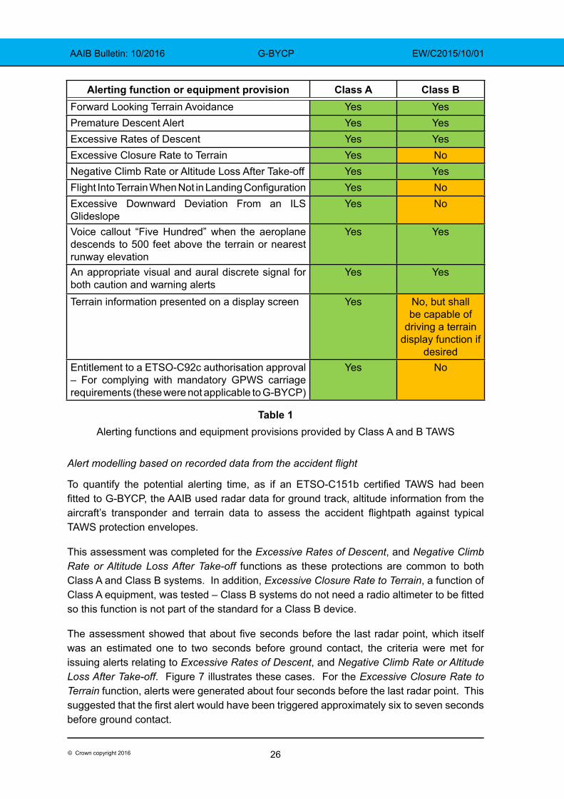
To quantify the potential alerting time, as if an ETSO‑C151b certified TAWS had been fitted to G‑BYCP, the AAIB used radar data for ground track, altitude information from the aircraft’s transponder and terrain data to assess the accident flightpath against typical TAWS protection envelopes.
This assessment was completed for the Excessive Rates of Descent, and Negative Climb Rate or Altitude Loss After Take-off functions as these protections are common to both Class A and Class B systems. In addition, Excessive Closure Rate to Terrain, a function of Class A equipment, was tested – Class B systems do not need a radio altimeter to be fitted so this function is not part of the standard for a Class B device.
The assessment showed that about five seconds before the last radar point, which itself was an estimated one to two seconds before ground contact, the criteria were met for issuing alerts relating to Excessive Rates of Descent, and Negative Climb Rate or Altitude Loss After Take-off. Figure 7 illustrates these cases. For the Excessive Closure Rate to Terrain function, alerts were generated about four seconds before the last radar point. This suggested that the first alert would have been triggered approximately six to seven seconds before ground contact.
27© Crown copyright 2016
AAIB Bulletin: 10/2016 G-BYCP EW/C2015/10/01
To verify the AAIB’s modelling, a manufacturer of TAWS was asked to perform its own simulation which confirmed that the Excessive Rates of Descent, and Negative Climb Rate or Altitude Loss After Take-off protections would have activated approximately four seconds before the last radar point. However, the precise timing and order of the alerts could not be specified due to the low update rate of the source data. The manufacturer also remarked that, due to the priority which some alerts have, lower priority alerts may have been supressed in the accident sequence in favour of other higher priority alerts depending on the exact sequence of events. Additionally, the manufacturer commented that, based on G-BYCP’s ground track, it was possible that Bank Angle alerts, typically an additional function of a Class A system, may have been generated but it was not possible to state this conclusively due to a lack of bank angle information in the radar data.
Figure 7TAWS Simulation
Simulator trial
Flight profile
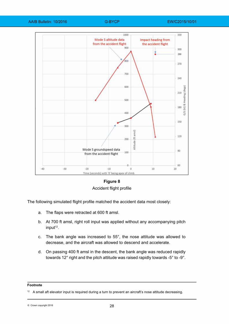
The AAIB ‘flew’ a B200 King Air full‑flight simulator in an attempt to match the accident flight profile derived from radar data (ground track, altitude and groundspeed) and physical evidence (the track of the wreckage trail, and the aircraft attitude at impact). The simulator was programmed to reflect the weight and balance of G‑BYCP and the environmental conditions on the day of the flight. The aircraft was turned onto a heading of 205°M after takeoff and the climb was flown both manually and with the autopilot engaged. Takeoff power was set for the duration of each flight. The flight profile generated from radar and physical data, which the trial attempted to match, is shown in Figure 8. Time is set to zero at the apex of the climb for comparison purposes.
28© Crown copyright 2016
AAIB Bulletin: 10/2016 G-BYCP EW/C2015/10/01
Figure 8Accident flight profile
The following simulated flight profile matched the accident data most closely:
a. The flaps were retracted at 600 ft amsl.
b. At 700 ft amsl, right roll input was applied without any accompanying pitch input12.
c. The bank angle was increased to 55°, the nose attitude was allowed to decrease, and the aircraft was allowed to descend and accelerate.
d. On passing 400 ft amsl in the descent, the bank angle was reduced rapidly towards 12° right and the pitch attitude was raised rapidly towards -5° to -9°.
Footnote12 A small aft elevator input is required during a turn to prevent an aircraft’s nose attitude decreasing.
29© Crown copyright 2016
AAIB Bulletin: 10/2016 G-BYCP EW/C2015/10/01
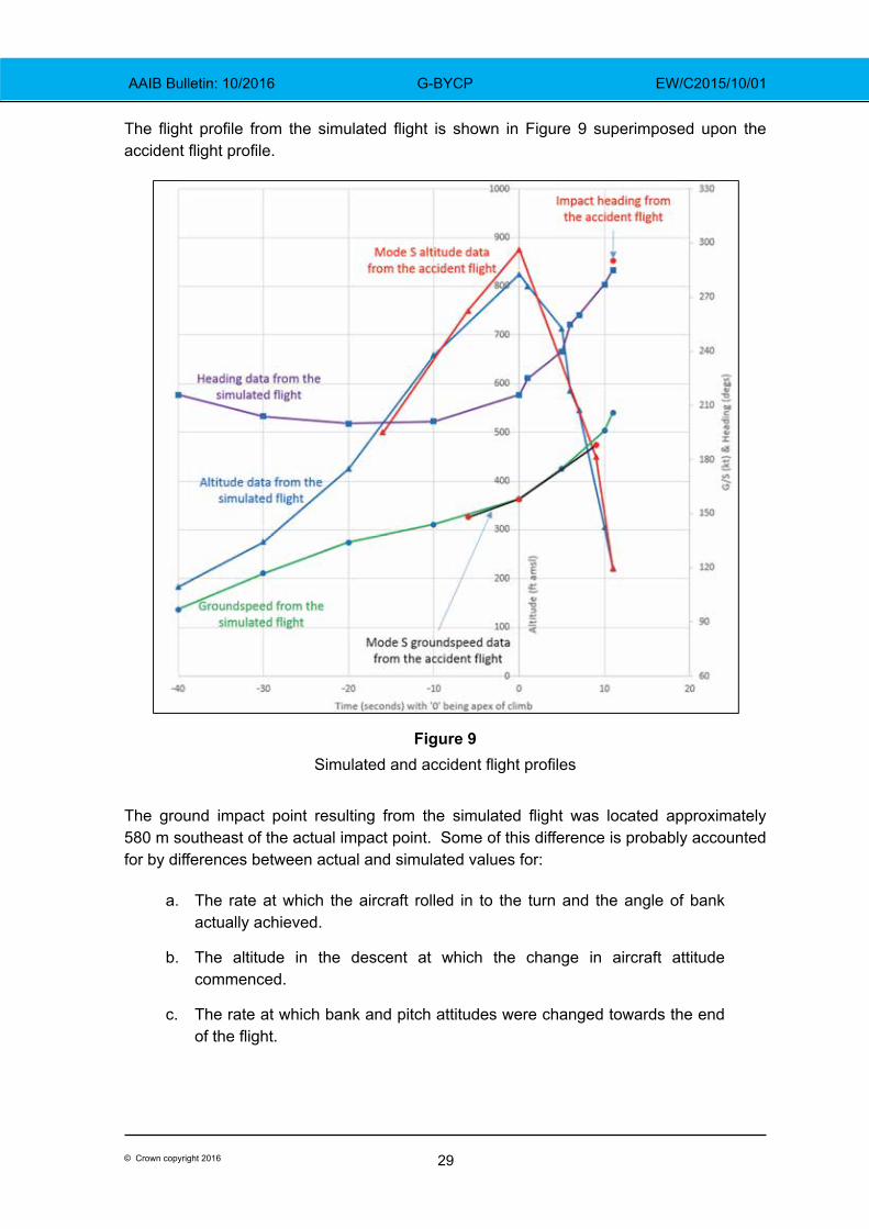
The flight profile from the simulated flight is shown in Figure 9 superimposed upon the accident flight profile.
Figure 9Simulated and accident flight profiles
The ground impact point resulting from the simulated flight was located approximately 580 m southeast of the actual impact point. Some of this difference is probably accounted for by differences between actual and simulated values for:
a. The rate at which the aircraft rolled in to the turn and the angle of bank actually achieved.
b. The altitude in the descent at which the change in aircraft attitude commenced.
c. The rate at which bank and pitch attitudes were changed towards the end of the flight.
30© Crown copyright 2016
AAIB Bulletin: 10/2016 G-BYCP EW/C2015/10/01
On one trial run, the autopilot was engaged with a lateral mode active (heading mode) but without a vertical mode. This simulated the possibility that the pilot attempted to use the autopilot but did not engage a vertical mode. When the turn was initiated, bank angle was limited to below 30°, power was sufficient to prevent a decrease in the nose attitude and the aircraft continued to climb.
TAWS alerts
The simulator was equipped with a Honeywell Mk. VII EGPWS, a certified Class A TAWS, which provided information on the alerts that might have been generated in a flight profile similar to the accident flight. The following aural alerts were triggered during the simulated accident flight profile shown in Figure 9:
a. “bank angle” approximately one second after the aircraft began to descend (at approximately 580 ft agl) and ten seconds before ground contact.
b. “sink rate” approximately six seconds after the aircraft began to descend (at approximately 365 ft agl) and five seconds before ground contact.
c. “pull up” approximately seven seconds after the aircraft began to descend (at approximately 325 ft agl) and four seconds before ground contact.
The simulated profile shown in Figure 9 was repeated and ground contact was avoided by appropriate recovery action up to and including the point where the “pull up” alert was triggered.
Terrain awareness equipment fitted to G-BYCP
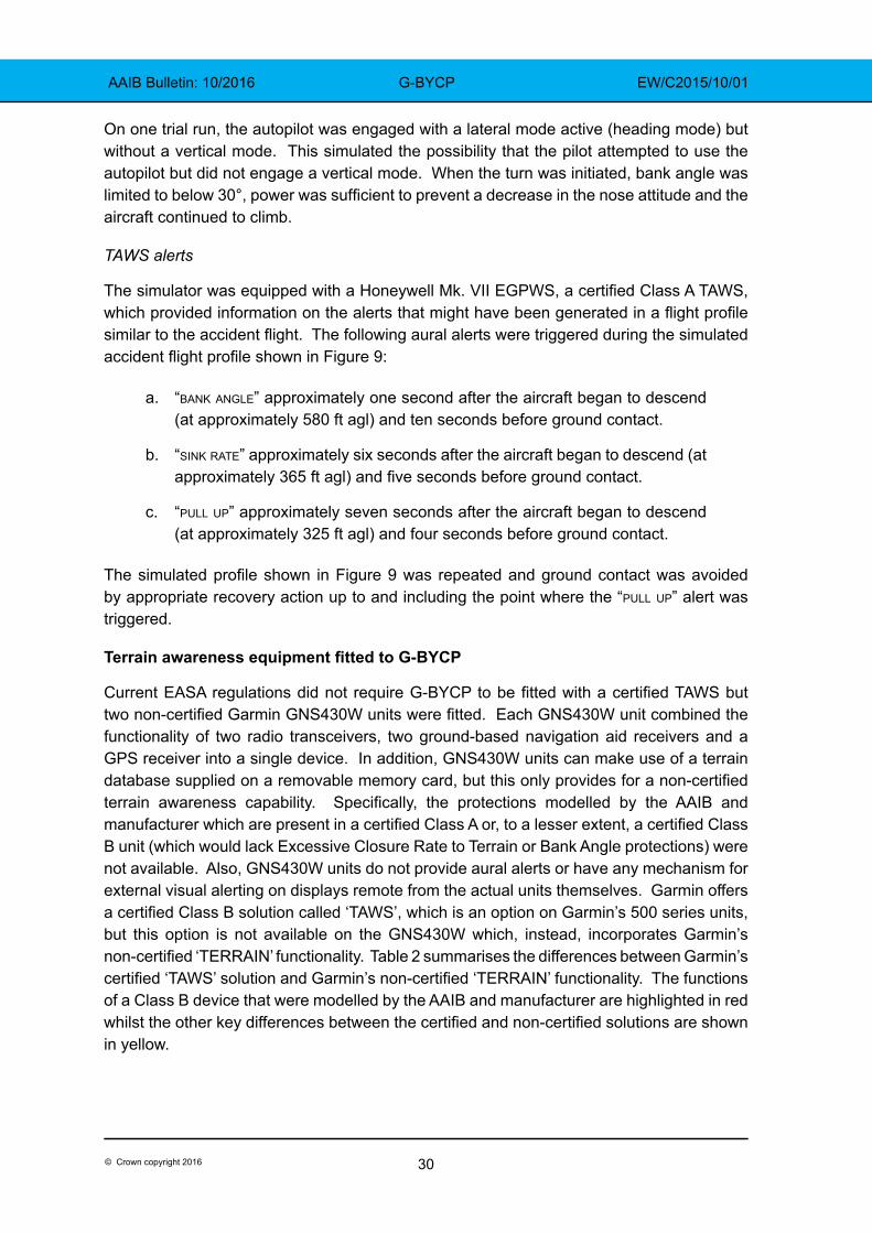
Current EASA regulations did not require G‑BYCP to be fitted with a certified TAWS but two non‑certified Garmin GNS430W units were fitted. Each GNS430W unit combined the functionality of two radio transceivers, two ground-based navigation aid receivers and a GPS receiver into a single device. In addition, GNS430W units can make use of a terrain database supplied on a removable memory card, but this only provides for a non‑certified terrain awareness capability. Specifically, the protections modelled by the AAIB and manufacturer which are present in a certified Class A or, to a lesser extent, a certified Class B unit (which would lack Excessive Closure Rate to Terrain or Bank Angle protections) were not available. Also, GNS430W units do not provide aural alerts or have any mechanism for external visual alerting on displays remote from the actual units themselves. Garmin offers a certified Class B solution called ‘TAWS’, which is an option on Garmin’s 500 series units, but this option is not available on the GNS430W which, instead, incorporates Garmin’s non‑certified ‘TERRAIN’ functionality. Table 2 summarises the differences between Garmin’s certified ‘TAWS’ solution and Garmin’s non‑certified ‘TERRAIN’ functionality. The functions of a Class B device that were modelled by the AAIB and manufacturer are highlighted in red whilst the other key differences between the certified and non‑certified solutions are shown in yellow.
31© Crown copyright 2016
AAIB Bulletin: 10/2016 G-BYCP EW/C2015/10/01
Table 2Certified ‘TAWS’ and non‑certified ‘TERRAIN’ functionality
(Reproduced with permission from Garmin International, Inc.)
32© Crown copyright 2016
AAIB Bulletin: 10/2016 G-BYCP EW/C2015/10/01
Terrain awareness equipment survey
The AAIB asked six commercial UK King Air operators about terrain awareness equipment fitted to their aircraft, whether certified or non‑certified, and, of 20 aircraft consisting mainly of King Air 200 and King Air 250 types, four were equipped with a certified solution. A further five were equipped with either Garmin GNS430, GNS530 or GTN750 series units, of which the GNS530 or GTN750 series can be upgraded to a certified TAWS. This suggested that a minimum of 11 aircraft were without any form of terrain awareness device and, if none of the GNS430, GNS530 or GTN750 series units had been upgraded, then 16 aircraft would not be equipped with a certified solution.
TAWS requirements and recommendations
EASA
In December 2015 the European Aviation Safety Agency (EASA) issued a Notice of Proposed Amendment (NPA), NPA2015‑21, which considered the carriage of certified TAWS on turbine‑powered aeroplanes. This covered those aeroplanes with a Maximum Certificated Take-off Mass (MCTOM) of 5,700 kg or less and a maximum operational passenger seating configuration (MOPSC) of between six and nine passengers. Comments on this document from interested parties were accepted by the EASA until 18 March 2016 when the consultation phase of EASA’s rulemaking process finished. At the time of writing, the EASA was reviewing the comments received before publishing a final opinion. However, the EASA draft opinion calls for Class B TAWS to be fitted to turbine‑powered aeroplanes with a MCTOM of 5,700 kg or less and a MOPSC of between six and nine, for which individual Certificates of Airworthiness will be first issued after 1 January 2019. This would only apply to commercial operations and affect newly built aeroplanes, and the existing fleet of aeroplanes, which would have included G-BYCP, would not be encompassed by such rulemaking nor would any such aeroplane operated privately.
ICAO
The International Civil Aviation Organisation (ICAO) sets out Standards and Recommended Practices for Contracting States including the United Kingdom. ICAO Annex 6, Part 1 considers Commercial Air Transport operations by aeroplanes. In this document, a recommendation is made that all turbine-powered aeroplanes of a MCTOM of 5,700 kg or less and authorised to carry more than five but not more than nine passengers should be equipped with a Ground Proximity Warning System. This document lists the functionality such a system should provide which, in effect, denotes a Class B TAWS. A similar recommendation, in effect for Class B TAWS, is made in ICAO Annex 6, Part 2 which covers General Aviation operations by aeroplanes. These recommendations do not distinguish between newly built aeroplanes or those currently in service.
The USA and Canada
In the United States, the Federal Aviation Administration (FAA) requires all turbine‑powered aeroplanes able to carry between six and nine passengers to be equipped with a Class B TAWS. This applies when these aeroplanes are operated under the provisions of Federal
33© Crown copyright 2016
AAIB Bulletin: 10/2016 G-BYCP EW/C2015/10/01
Aviation Regulations 14 CFR Parts 91 and 135. 14 CFR Part 135 addresses on-demand air transport whilst 14 CFR Part 91 applies to aeroplane operations not covered by another Federal Aviation Regulation Part thus including private use.
In Canada, Transport Canada (TC) under Canadian Aviation Regulations Subpart 703, requires Class B TAWS for both piston and turbine engine aeroplanes. This applies to aeroplanes involved in air taxi work with six or more passenger seats, excluding any pilot seats, unless operated under Day VFR provisions. Under the regulation applicable to commuter operations, Subpart 704, all aeroplanes with between six and nine passenger seats, excluding any pilot seats, whether piston or turbine engine powered, must be equipped with a Class B TAWS unless operating to Day VFR provisions. For private operations under Subpart 604, Subpart 605 (which covers aircraft equipment carriage) mandates Class B TAWS but only for turbine powered aeroplanes configured with between six and nine passenger seats, excluding any pilot seats.
These rules came into effect in 2001 in the USA and in 2012 in Canada. Both regulators applied these rules to aeroplanes already in service, but allowed a transition period of two and three years respectively to allow time for the necessary modifications to be made.
Flight Data and Voice Recorders requirements and rulemaking
There were no requirements for G‑BYCP to carry a flight data recorder or a cockpit voice recorder. EASA are rulemaking in this area and EASA rulemaking tasks RMT.0271 and RMT.0272 refer, a NPA was planned for publication in Quarter 1 of 2016.
Passengers on the flightdeck
CAA communication
CAA Flight Operations Communication (FODCOM) 21/2010, Passengers, sometimes called ‘pilots’ assistants’, was issued on 16 July 201013. The FODCOM explained that persons carried on an aircraft fall into one of two categories: crew or passengers. Some aircraft certificated for single‑pilot operations are fitted with a second pilot’s seat and the FODCOM stated:
‘For Commercial Air Transport and Public Transport operations … no person may be carried on the flight deck except … an operating crew member or a passenger permitted to occupy a flight deck seat in accordance with instructions in the operator’s operations manual’
and:
‘Unless they hold an appropriate flight crew licence entitling them to act as pilot on the flight, such persons can only be passengers and may not undertake any of the pilot’s duties, whether handling the controls, operating any aircraft equipment (including the radios) or completing flight documentation’
Footnote13 CAA Flight Operations Communication 21/2010. Available: http://publicapps.caa.co.uk/docs/33/FOD201021.pdf
34© Crown copyright 2016
AAIB Bulletin: 10/2016 G-BYCP EW/C2015/10/01
and:
‘Such passengers are not ‘pilot assistants’ or ‘safety pilots’ nor should they be permitted to contribute in any way to the operation of the aircraft.’
Although the FODCOM pre‑dated the implementation of EU 965/2012, the CAA confirmed that, in terms of regulatory requirements, the FODCOM was still valid. On 23 November 2015, the CAA issued Information Notice (IN) 2015/110, Passengers Carried on the Flight Deck Sometimes Called ‘Pilots’ Assistants’14. The IN was written in substantially the same terms as the FODCOM.
The CAA stated that, because the pilot in the right seat of G‑BYCP was not qualified on the B200 King Air, that person was a passenger.
Operator’s risk assessment
The operator’s Air Operator’s Certificate permitted its King Air aircraft to be operated with either one or two qualified pilots. The OMA stated that the minimum crew requirement for the King Air would be one pilot, but that:
‘When additional Crew members are carried over and above the minimum required they must be trained to a standard proficient to perform their assigned duties’
and:
‘All Flight Crew members must have a licence, rating, qualification … valid for the type of aircraft, type of flight and their function within the Flight Crew.’
In 2010, after FODCOM 21/2010 was issued, the operator undertook a risk assessment in relation to single-pilot operations. The assessment considered events that might trigger an ‘Undesirable Operational State’ (UOS) which might in turn lead to a major accident. The UOS was defined with reference to single‑pilot operations as a ‘severe reduction in ‘Spare Capacity’ to deal with unforeseen circumstances’. Risk control barriers intended to prevent the reduction in spare capacity were:
a. Stricter regulatory medical requirements for single‑pilot commercial operations.
b. Minimum training requirements in the OMA with regards to hours and experience.
c. Six‑monthly Operational Proficiency Checks conducted in the aircraft.
d. More restrictive flight time limitations and operational procedures, including in relation to the use of the autopilot.
Footnote14 CAA Information Notice IN-2015/110. Available: https://publicapps.caa.co.uk/docs/33/
InformationNotice2015110.pdf
35© Crown copyright 2016
AAIB Bulletin: 10/2016 G-BYCP EW/C2015/10/01
Barriers intended to recover the situation before the UOS could lead to an ‘Accident Outcome’ were: training; Crew Resource Management (CRM); and pilot experience.
The operator judged that the first set of (preventative) barriers would fail to prevent a UOS approximately once in every 100 sectors, and the second set of (recovery) barriers would fail to prevent the UOS becoming an accident once in every 10,000 occurrences. The overall risk of an accident was quantified as one in every one million sectors and the result of the assessment, according to the assessment nomenclature, was ‘Improve’15.
The operator undertook the risk assessment again with an additional preventative barrier ie the use of a ‘second crew member’. The operator judged that the effect of the additional crew member would be to reduce to once in every 10,000 sectors the probability that a UOS would occur. The operator made no adjustment to the effectiveness of the recovery barriers. In these circumstances, the overall risk of an accident became one in every 100 million sectors and the result of the assessment was ‘Monitor’.
The output from the risk assessment was to:
‘Consider mandating the presence of [an] additional crew member or second pilot on every flight for the King Air Fleet.’
The risk assessment is reviewed annually by the operator.
Following the risk assessment, the operator agreed with the CAA to remove from its Operations Manual all references to ‘Pilot’s Assistants’ and replace them with ‘Additional crew members’. The additional crew members would have ‘no operational control of the aircraft’.
The operator stated that the duties of the additional crew member during flight were:
‘Read the checklistComplete the ‘Plog’16
Operate the R/TAdhere to [company] SOPs17
Monitor the Captain’s actions and be ready to assist if the Captain requires any assistance.Express his/her opinion on any action taken by the Captain that may seem abnormal or unclear.
Follow all briefs given by the Captain.’
Footnote15 The overall probability of the final (accident) outcome was calculated as the product of the two individual
probabilities that the barriers would fail.16 Plog: Pilot’s log.17 SOP: Standard Operating Procedure.
36© Crown copyright 2016
AAIB Bulletin: 10/2016 G-BYCP EW/C2015/10/01
Crew composition in the King Air
The operator’s OMB outlined the company’s ‘philosophy of operation’ for the King Air and stated that:
‘[The normal procedures] section [of OMB] assumes that a second pilot is carried. The second pilot carries out the Pilot Monitoring [PM] role. When two pilots are not carried, the Captain will complete all items.’
The SOP philosophy stated that, in two-crew operations, the PM would, among other things, monitor the flightpath and point out significant un‑planned deviations. The PM would call “bank angle” should the angle of bank exceed 30° and “sink rate” should there be an excessive rate of descent ‘according to phase of flight and altitude’.
The duties and procedures to be used by the additional crew member were not contained in the operator’s OMB.
Analysis
Engineering
Examination of the engines and propellers did not reveal any evidence of pre-accident defects and the observed damage was similar in nature for the left and right engines and propellers, indicating that there was no asymmetric loss of thrust. Performance analysis conducted by the aircraft manufacturer concluded that the accident flight path, as recorded by secondary radar, was only possible with both engines operating and producing medium to high power during the majority of the period of radar coverage. It was therefore concluded that the engines and propellers were probably operating normally prior to impact.
The landing gear was found in the retracted position, which was consistent with the phase of flight when the accident occurred. The engineering investigation was not able to establish the reason for the difference in flap jackscrew actuator positions between the fully extended left inboard flap actuator, and the remaining three flap actuators, which were found in a position consistent with flaps retracted. No pre‑accident defect was observed for the recovered components of the left inboard flap drive system. Had a failure of this system occurred prior to takeoff on the accident flight, the degree of flap asymmetry implied by the extended left inboard flap actuator would have also required a second, independent, failure of the flap asymmetry protection system. Whilst it was therefore considered unlikely that the left inboard flap was extended during the accident flight, this possibility could not be completely discounted.
There was strong evidence that the captain’s primary attitude indicator was functioning correctly during the accident flight, and physical evidence of the pitch and roll angles displayed at the moment of impact correlated closely with the tree strike geometry and wreckage distribution noted at the accident site. All discontinuities identified in the aircraft’s flying control system were consistent with the impact and subsequent aircraft breakup. The possibility of a pre-accident control restriction, or jam, could not be discounted due to the high degree of fragmentation of the aircraft and subsequent fire damage. However, if
37© Crown copyright 2016
AAIB Bulletin: 10/2016 G-BYCP EW/C2015/10/01
there was such a restriction or jam, it must have freed itself before impact because the late change in aircraft attitude showed that the aircraft was controllable late in the flight.
Technical log entries
The use of email ‘Engineering Reports’ to record aircraft technical defects circumvented the requirements of EASA Part M regulation M.A.403 for correctly recording defects in the aircraft technical log and aircraft maintenance records. A review of the ‘Engineering Report’ emails for G-BYCP, over nine months of operation immediately preceding the accident flight, revealed a high number of defects that were not recorded in the aircraft technical log, and for which rectification actions were not recorded in the aircraft’s technical records. It was clear that the operator was aware of the aircraft’s defect history and that it used the content of the ‘Engineering Report’ emails to coordinate defect rectification during the scheduled Phase 1 maintenance inspection in June 2015. Where defects were rectified in this manner, the rectification interval was well outside MEL allowable time limits.
Despite these findings however, the investigation found no evidence that the defects recorded in the ‘Engineering Reports’ directly contributed to the accident.
The following safety action was taken:
The operator has issued a Flight Crew Notice to all crews informing them of the suspension of the ‘Engineering Report’ email system. The notice instructed them to follow the correct technical log procedures as set out in the operator’s Operations Manual Parts A and B, and the relevant aircraft Minimum Equipment List.
Flightpath
Simulator modelling suggested that the aircraft took off and began its initial climb in accordance with standard procedures. The altitude selector was found to be reading 2,300 ft, consistent with the ATC clearance to remain clear of controlled airspace which began at 2,500 ft amsl. The simulator trial showed that, had the pilot engaged the autopilot in heading mode, but omitted to engage a vertical mode, the aircraft would have continued to climb during the turn. If he believed the autopilot to be engaged when it was not, he would have noticed his error when he commanded the turn and the heading remained constant. Given that the operator expected the departure to be flown manually, it was concluded that the autopilot was probably not engaged. Once the aircraft began to turn right, the simulated profile which matched radar and physical evidence most closely suggested that the aircraft rolled to approximately 55° angle of bank without there being a pitch input to the elevators which was required to prevent the nose attitude decreasing. Without the pitch input, the aircraft would have continued to turn but would also have begun to descend.
The apex of the departure flightpath was approximately 875 ft amsl and below the top of the cloud. It is likely, therefore, that the aircraft was in IMC at the time it began to turn right and descend. Radar data implied a rate of descent of over 7,000 fpm and a downward flightpath angle of approximately 20° as the aircraft descended through approximately 225 ft above
38© Crown copyright 2016
AAIB Bulletin: 10/2016 G-BYCP EW/C2015/10/01
the accident site. Simulator trials suggested that the aircraft reached a maximum angle of bank of about 55° right. Physical evidence suggested that, by the time of impact, the downward flightpath angle had reduced to approximately 5° to 9°, and the angle of bank to approximately 12° right. The late change in aircraft attitude showed that the aircraft was controllable in roll and pitch immediately before impact. It also suggested a conscious attempt to recover the aircraft, probably because one or both of the pilots gained an appreciation of the aircraft’s extreme attitude from cockpit instruments, or from external visual references which might have appeared as the aircraft descended.
Flap asymmetry
During the preliminary cockpit procedure, the pilot would have extended the flaps to 100% and, had they not extended, it is unlikely that this would have been missed during the walk‑round inspection. Before starting engines, the flaps would have been selected to up and, after starting engines, they would have been selected to 100% and then 40%. If there was a failure of the flap drive system, therefore, it would have occurred either when the flaps were selected to up before start, or to 40% after start, and the aircraft would have departed with the inboard flap section at 100% and the remaining flaps at 40%. In these circumstances, the flap position indicator in the cockpit would have indicated 40%, as expected, because it senses flap position on the right wing.
Had there been a flap asymmetry as described above, when the flaps were selected to up after takeoff, any asymmetric aerodynamic effect already present would have increased as three of the four flap sections retracted. The flap position indicator would have indicated (as expected) that the flaps were retracted. If the flaps were retracted in accordance with standard procedures (at about 600 ft amsl), any aerodynamic effect would have been felt just as the aircraft began to turn right. Information from the manufacturer suggested that the effects would have been noticeable to the pilot but the aircraft would have been controllable in these circumstances. It was concluded that, even if there had been a flap asymmetry, its effects would not have been sufficient in isolation to cause a loss of control but they would probably have been distracting.
Additional crew member
The additional crew member held an ATPL and a multi-pilot instrument rating valid on two-crew aircraft operated by the operator of G-BYCP but, because he was not type-rated on the King Air, he was a passenger on this flight. Additional crew members were used by the operator because, following a risk assessment for single-pilot operations in the King Air, it was judged that their presence would reduce the likelihood that a single pilot would experience a ‘severe reduction in ‘Spare Capacity’ to deal with unforeseen circumstances’. The additional crew member would have ‘no operational control of the aircraft’ but would have duties which included: adhering to company SOPs; monitoring the captain’s actions and assisting if required; and expressing an opinion on any action by the captain that appeared abnormal or unclear. Company SOPs, contained in the OMB and written assuming the aircraft would be operated by two type‑rated pilots, stated that the PM would call “bank angle” should the angle of bank exceed 30° and “sink rate” should there be an excessive rate of descent ‘according to phase of flight and altitude’.
39© Crown copyright 2016
AAIB Bulletin: 10/2016 G-BYCP EW/C2015/10/01
As an experienced pilot with an instrument rating, the additional crew member was able to interpret flight instruments to gain an appreciation of aircraft attitude and performance. Therefore, it was likely that, had he been aware that the aircraft was over-banking and descending, he would have brought it to the attention of the pilot. It was probably the increasing bank angle (without a corresponding pitch input) which led to the descent, and any descent during the initial climb after takeoff could be considered excessive for that phase of flight and altitude. Each of the calls, “bank angle” and “sink rate”, would therefore have been appropriate in the circumstances.
Data from radar and the simulator trial showed that the aircraft began to descend when it was approximately 650 ft above the accident site and after it exceeded 30° angle of bank. It was concluded that, had the “bank angle” and “sink rate” calls been made as soon as they became appropriate, sufficient height remained to allow the aircraft to recover to safe flight.
The possibility of pilot incapacitation
The post-mortem report raised the possibility that the pilot became incapacitated with symptoms ranging from impaired consciousness to sudden death. In these circumstances, the additional crew member would have had to recognise that the pilot was incapacitated, take control of the aircraft, assess its attitude and flightpath, and initiate recovery action. There would inevitably have been a delay between the moment control was lost and the moment incapacitation was confirmed which would have reduced the time available to assess the flightpath and recover the aircraft. If this was the scenario, it suggested that the additional crew member took recovery action but not in time to achieve climbing flight before the aircraft struck the ground.
Missing evidence
The investigation had no evidence from within the cockpit relating to the period when the aircraft began to turn and descend. In particular, there was no evidence relating to individual actions by the occupants or the interaction between them. Therefore, the investigation could not determine:
a. Which pilot was flying the aircraft, although it was expected to have been the commander and there was no evidence to contradict this expectation.
b. Whether the pilots noticed a flap asymmetry, if one existed, and whether it became a distraction to them both to the exclusion of maintaining a safe flightpath.
c. Whether, or when, the non-handling pilot noticed that the aircraft attitude was outside normal parameters and brought it to the attention of the handling pilot.
40© Crown copyright 2016
AAIB Bulletin: 10/2016 G-BYCP EW/C2015/10/01
TAWS
The simulator trial and TAWS modelling suggested that, had the aircraft been fitted with a Class B TAWS, the circumstances would have satisfied system criteria to generate alerts indicating that the aircraft was descending after takeoff and, separately, had an excessive rate of descent. In a class A TAWS installation, alert criteria would most likely have been satisfied in relation to the bank angle and also for an excessive closure rate with the terrain. System logic would probably have prioritised particular alerts and supressed others, and the radar data available was not of sufficient fidelity to establish the order of alerts that would actually have been triggered. However, it was concluded that, had either class of TAWS been fitted, the crew would probably have been alerted to the fact that the flight path was deviating from the norm at an altitude high enough to allow the aircraft to be recovered to safe flight. This conclusion was supported by the simulator trial in which terrain contact was avoided by appropriate recovery action up to and including the point where the “pull up” alert was triggered.
Currently, within the EU, certified TAWS are not required for this category of aeroplane used commercially, unlike the current rules for regulators such as the FAA and Transport Canada which also address privately operated aeroplanes. Further, the draft opinion within the EASA’s NPA on this subject, although affecting new build aeroplanes (those issued with individual certificate of airworthiness after 1 January 2019) would exclude aeroplanes currently in service.
The AAIB survey of six commercial UK King Air operators showed that the majority of such aeroplanes were not fitted with certified TAWS, nor were any operators planning on retrofitting their fleets. Non‑certified terrain awareness solutions do not offer the same level of protection or mechanisms for alerting pilots, such as aural alerts, that are required on certified units. In this accident, it is likely that a certified TAWS system would have alerted the crew to the situation in time to change the outcome. Therefore, to provide protection against inadvertent flight into terrain for this class of aeroplane, whether operated privately or commercially, the following three Safety Recommendations are made:
Safety Recommendation 2016-055
It is recommended that the European Aviation Safety Agency require all in‑service and future turbine aircraft with a Maximum Certificated Takeoff Mass of 5,700 kg or less and with a maximum operational passenger seating configuration of between six and nine passengers to be fitted with, as a minimum standard, a Class B Terrain Awareness and Warning System certified to ETSO-C151b.
41© Crown copyright 2016
AAIB Bulletin: 10/2016 G-BYCP EW/C2015/10/01
Safety Recommendation 2016-056
It is recommended that the International Civil Aviation Organisation revise Annex 6 to the Convention on International Civil Aviation, Part 1 (International Commercial Air Transport – Aeroplanes) to upgrade recommendation 6.15.5 [carriage of TAWS on turbine aeroplanes with a Maximum Certificated Takeoff Mass of 5,700 kg or less and authorised to carry more than five but not more than nine passengers] to a standard.
Safety Recommendation 2016-057
It is recommended that the International Civil Aviation Organisation revise Annex 6 to the Convention on International Civil Aviation, Part 2 (International General Aviation – Aeroplanes) to upgrade recommendation 2.4.11.2 [carriage of TAWS on turbine aeroplanes with a Maximum Certificated Takeoff Mass of 5,700 kg or less and authorised to carry more than five but not more than nine passengers] to a standard.
Risk control ‘barriers’ to prevent loss of aircraft control and terrain impact
Risk control barriers in place to try and prevent an unintentional deviation from normal in‑flight parameters include:
a. Six-monthly medical examinations for pilots over 40 years old carrying out single-pilot commercial operations carrying passengers.
b. Proficiency in manual handling skills
c. Adherence to automation policy.
d. Flight crew detect and recognise the mishandling via monitoring.
e. Flight crew detect and recognise the mishandling via automated alerts.
f. Flight crew correct the mishandling.
g. Automated features limit the deviation from normal parameters.
Barrier a aimed to reduce the likelihood that a pilot operating in a single-pilot environment will become medically incapacitated at the controls by requiring that pilot to undergo more frequent medical examinations than a pilot operating in a multi‑pilot environment. This barrier cannot prevent incapacitation, however, especially when some medical conditions are difficult to predict or occur spontaneously.
Barrier c required the autopilot to be engaged above 1,000 ft agl after takeoff and, because it is likely that the departure was flown manually, the automation policy did not operate as an effective barrier to loss of control during this flight.
Barriers e and g were ineffective because the aircraft was not fitted – and was not required to be fitted – with TAWS, or automated features to limit the deviation of in‑flight parameters. Recommendations 2016-055 to 2016-057 are intended to make barrier e
42© Crown copyright 2016
AAIB Bulletin: 10/2016 G-BYCP EW/C2015/10/01
more effective because it is likely in this case that TAWS would have alerted the pilot and/or additional crew member to the initial deviation from the expected flightpath. If the pilot was incapacitated, this might have triggered an earlier response from the additional crew member.
Barriers b, d and f relate to pilot manual handling skills and the ability to detect, recognise and correct any mishandling. These barriers were compromised either because the pilot had insufficient skill to maintain control of his aircraft or because he became incapacitated.
Risk control barriers intended to try and prevent an unintended deviation from normal in‑flight parameters leading to loss of control and impact with terrain include:
h. ATCO identifies the issue and alerts the flight crew.
i. Automated systems assist aircraft recovery.
j. Flight crew perform upset recovery procedure in response to monitoring and/or automated warnings.
k. TAWS alerts flight crew to inadequate terrain separation.
l. Flight crew carry out terrain avoidance manoeuvre in response to visual, ATCO or TAWS warning.
m. Flight crew detect and recognise the potential conflict visually.
Barriers h, i and k were ineffective during this flight because no ATC service was provided at the aerodrome, and the aircraft was not fitted with relevant automated systems or TAWS. Barriers j and l relied upon monitoring and visual assessment because of the lack of automated warnings, ATC or TAWS. Safety Recommendations 2016-055 to 2016-057 are intended to strengthen barriers j, k and l because it was likely that TAWS alerts would have been triggered in time for the aircraft to be recovered to safe flight. It was likely that the late change in aircraft attitude was in response to the monitoring of flight instruments or a visual assessment of ground features appearing as the aircraft descended. If so, the recovery manoeuvre could not be completed in the height available and barrier m was also ineffective.
Conclusion
Examination of the powerplants showed that they were probably producing medium to high power at impact. There was contradictory evidence as to whether or not the left inboard flap was fully extended at impact but it was concluded that the aircraft would have been controllable even if there had been a flap asymmetry. The possibility of a pre‑accident control restriction could not be discounted, although the late change of aircraft attitude showed that, had there been a restriction, it cleared itself.
The evidence available suggested a loss of aircraft control while in IMC followed by an unsuccessful attempt to recover the aircraft to safe flight. It is possible that the pilot lost control through a lack of skill but this seemed highly unlikely given that he was properly

43© Crown copyright 2016
AAIB Bulletin: 10/2016 G-BYCP EW/C2015/10/01
licensed and had just completed an extensive period of supervised training. Incapacitation of the pilot, followed by an attempted recovery by the additional crew member, was a possibility consistent with the evidence and supported by the post-mortem report. Without direct evidence from within the cockpit, it could not be stated unequivocally that the pilot became incapacitated. Likewise, loss of control due to a lack of skill, control restriction or distraction due to flap asymmetry could not be excluded entirely. On the balance of probabilities, however, it was likely that the pilot lost control of the aircraft due to medical incapacitation and the additional crew member was unable to recover the aircraft in the height available.


![AAIB Bulletin 3/2020 - GOV UK · AAIB Bulletin: 3/2020 G-ATBJ EW/C2018/02/01 it [auxiliary hydraulic pressure] we haven’t got enough oomph in the systems now”. During the after‑start](https://img.pdfslide.us/doc/110x75/5f6478f23476ee446a4119ec/aaib-bulletin-32020-gov-uk-aaib-bulletin-32020-g-atbj-ewc20180201-it-auxiliary.jpg)