Embed Size (px)
Citation preview
Staff Report Raleigh Appearance Commission Administrative Alternate Request
Case File / Name: AAD-3-20 – 5101 Capital Boulevard General Location: Capital Boulevard and Spring Forest Road Owner: Sampson Bladen Oil Company Contact: Stan Wingo, McAdams, [email protected] Cross- Reference: ASR-0072-2019
Request: The applicant requests administrative alternates for UDO Section 1.5.6. Build-to and 1.5.8. Pedestrian Access.
Nature of Request: UDO Section 1.5.6. Build-to A. Defined: 1. The build-to is the area on the lot where a certain percentage of the front
principal building façade must be located, measured as a minimum and maximum setback range from the edge of the proposed or existing right-of-way, whichever is greater.
2. The required percentage specifies the amount of the front building façade that must be located in the build-to, measured based on the width of the building divided by the width of the site or lot.
B. Intent: 1. The build-to is intended to provide a range for building placement that
strengthens the street edge along the right-of-way, establishing a sense of enclosure by providing spatial definition adjacent to the street.
2. The building edge can be supplemented by architectural elements and certain tree plantings aligned in a formal rhythm. The harmonious placement of buildings to establish the street edge is a principal means by which the character of an area or district is defined.
3. The build-to range is established to accommodate some flexibility in specific site design while maintaining the established street edge.
C. General Requirements: 1. On corner lots, a building façade must be placed within the build to for the
first 30 feet along the street extending from the block corner. 2. With the exception of parking areas, all structures and uses customarily
allowed on the lot are permitted in the build-to area. 3. Any common area is not required to meet the build-to requirements 4. Riparian Buffers, Floodways, areas of steep slope (defined as slopes in
excess of 25%), pre-established and recorded Tree Conservation Areas and portions of property encumbered by overhead electric transmission lines rated to transmit 230 Kv, for any second driveway required by this code that must cross the build-to area, the additional width of the driveway up to a
City of Raleigh Urban Design Center One Exchange Plaza
Suite 100 Raleigh, NC 27601
(919) 996-4639 www.raleighnc.gov
maximum of 25’, and City of Raleigh utility easements shall not be considered when calculating the build-to percentage or build-to range.
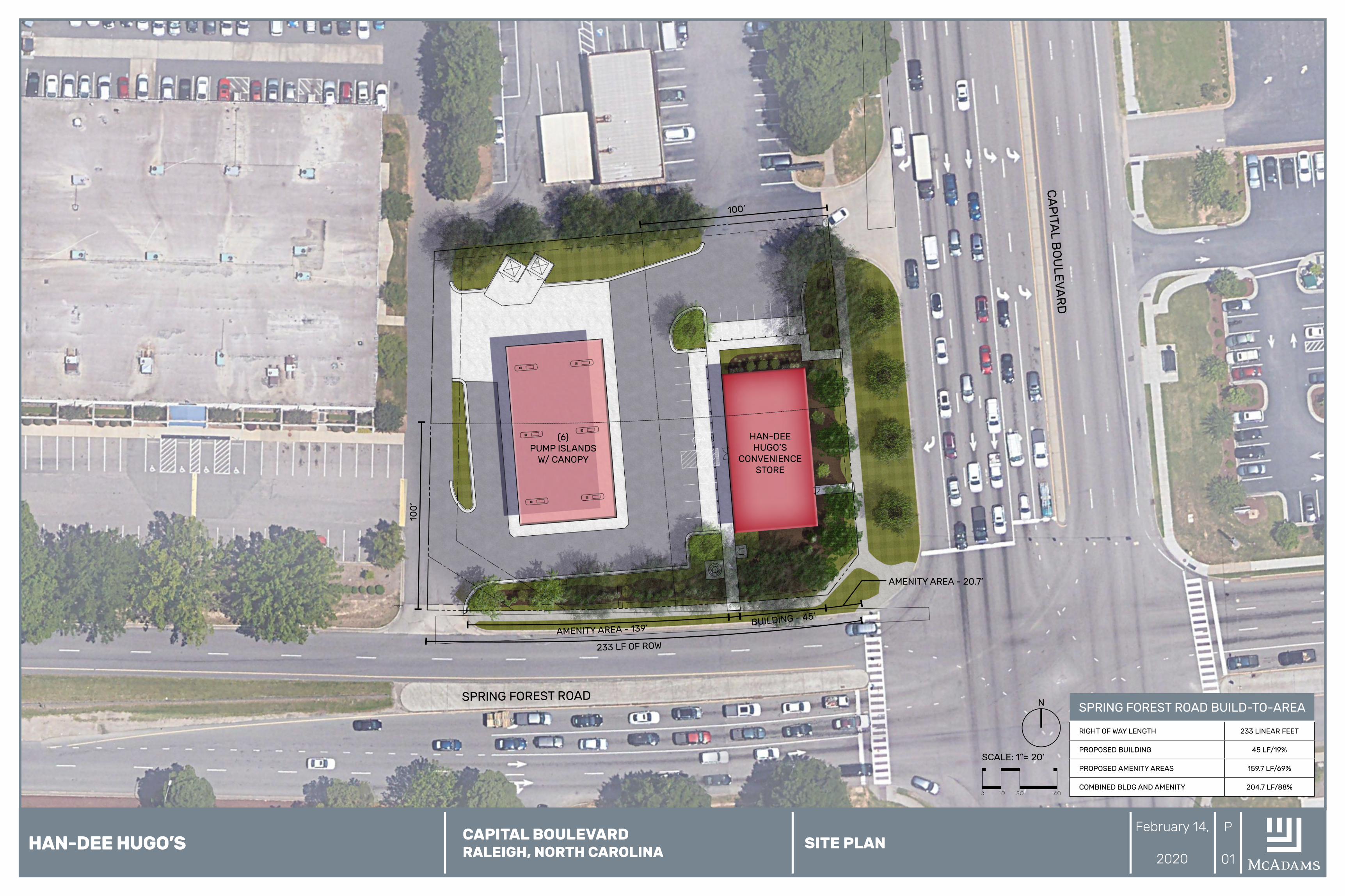
The applicant is proposing to develop gas station within an Industrial Mixed Use, 3 Story, Parking Limited Frontage (IX-3-PL) zoned district. Since the site has a Parking Limited frontage and a General Building type, the build-to is 50% of the lot width between 0’-100’ of the primary street. Both Capital Boulevard and Spring Forest Road have been designated as Primary Streets. As proposed, the building meets the build-to for Capital Boulevard but is too small to meet the primary street build-to for Spring Forest Road, occupying only 22.1%. The applicant is proposing an amenity area along Spring Forest Road that will include landscaping, picnic areas, and sidewalk access to the right-of-way. With the amenity area included, the combined building and amenity area will occupy 88% of the build-to.
Additional UDO Sections: Sec. 1.5.3. Outdoor Amenity Area
B. Intent 1. Outdoor amenity areas are intended to provide usable on-site open space in
both residential and non-residential developments for the healthy enjoyment of occupants, invitees and guests of the development.
2. In more intensely developed urban contexts, outdoor amenity areas are also intended to provide visual breaks.
C. General Requirements 1. Where outdoor amenity area is required, it must be provided on-site and
must be available for use by or as an amenity for the occupants, invitees and guests of the development.
2. All required outdoor amenity areas must be ADA accessible. 3. Required outdoor amenity area may be met in 1 contiguous open area or in
multiple open areas on the lot; however, to receive credit, each area must be at least 10 feet in width and length.
4. Required outdoor amenity area may be located at or above grade. 5. Required outdoor amenity area cannot be parked or driven upon, except for
emergency access and permitted temporary events. 6. In all other districts except DX-, required outdoor amenity area may be
covered but cannot be enclosed. 7. Above-ground stormwater detention facilities shall not be considered an
outdoor amenity area. 8. Tree Conservation areas shall not be considered an outdoor amenity area.
Sec. 3.4.5.C. Parking Limited (-PL) C. Build-to C1. Primary street build-to (min/max) 0’/100’ C2. Building width in primary build-to (min) 50%
C3. Side street build-to (min/max) 0’/100’ C4. Building width in side build-to (min) 25%
Administrative Alternate Findings: Sec. 1.5.6. Build-to
The Planning and Development Officer may in accordance with Sec. 10.2.17. reduce the build-to requirement, subject to all of the following findings:
1. The approved alternate meets the intent of the build-to regulations; 2. The approved alternate conforms with the Comprehensive Plan and adopted
City plans; 3. The approved alternate does not substantially negatively alter the character-
defining street wall or establish a build-to pattern that is not harmonious with the existing built context;
4. The change in percentage of building that occupies the build-to area or increased setback does not negatively impact pedestrian access, comfort or safety; and
5. Site area that would have otherwise been occupied by buildings is converted to an outdoor amenity area under Sec. 1.5.3.B.
Comprehensive Plan Guidance:
Policy LU 2.1 - Placemaking Development within Raleigh’s jurisdiction should strive to create places, streets,
and spaces that in aggregate meet the needs of people at all stages of life, are visually attractive, safe, accessible, functional, inclusive have their own identity, and maintain or improve local character. Policy LU 2.2 – Compact Development New development and redevelopment should use a more compact land use pattern to support the efficient provision of public services, improve the performance of transportation networks, preserve open space, and reduce the negative impacts of low intensity and non-contiguous development. Policy LU 4.5 – Connectivity New development and redevelopment should provide pedestrian and vehicular connectivity between individual development sites to provide alternative means of access along corridors. Policy LU 5.1 – Reinforcing the Urban Pattern New development should be visually integrated with adjacent buildings, and more generally with the surrounding area. Quality design and site planning is required so that new development opportunities within the existing urban fabric of Raleigh are implemented without adverse impacts on local character and appearance.
Policy LU 7.4 – Scale and Design of New Commercial Uses New uses within commercial districts should be developed at a height, mass, scale, and design that is appropriate and compatible with surrounding areas.
Policy T 2.9 – Curb Cuts The development of curb cuts along public streets—particularly on major streets—should be minimized to reduce vehicular conflicts, increase pedestrian safety, and improve roadway capacity.
Policy UD 1.4 – Maintaining Facade Lines Maintain the established facade lines of neighborhood streets by aligning the front walls of new construction with the prevailing facades of adjacent buildings, unless doing so results in substandard sidewalks. Avoid violating this pattern by
placing new construction in front of the historic facade line unless the streetscape is already characterized by such variations. Where existing facades are characterized by recurring placement of windows and doors, new construction should complement the established rhythm. Policy UD 2.1 – Building Orientation Buildings in mixed-use developments should be oriented along streets, plazas, and pedestrian ways. Their facades should create an active and engaging public realm. Policy UD 4.1 – Public Gathering Spaces Encourage the development of public gathering spaces within all developments. Such spaces should be designed to attract people by using common and usable open space, an enhanced pedestrian realm, streetscape activation, and retail uses. Policy UD 4.2 – Streets as Public Spaces Design streets as the main public spaces scaled for pedestrian use within City Growth, TOD, and Mixed-use Centers as designated on the Urban Form Map.
Policy UD 5.1 – Contextual Design Proposed development within established neighborhoods should create or enhance a distinctive character that relates well to the surrounding area. Policy UD 6.2 – Ensuring Pedestrian Comfort and Convenience Promote a comfortable and convenient pedestrian environment by requiring that buildings face the sidewalk and street area, avoid excessive setbacks, and provide direct pedestrian connections. On-street parking should be provided along pedestrian-oriented streets and surface parking should be to the side or in the rear. This should be applied in new development, wherever feasible, especially on Transit Emphasis and Main Street corridors and in mixed-use centers.
Policy UD 7.3 – Design Guidelines The Design Guidelines in Table UD-1 shall be used to review rezoning petitions
and development applications for mixed-use developments; or rezoning petitions and development applications along Main Street and Transit Emphasis Corridors or in City Growth, TOD, and Mixed-Use centers, including preliminary site plans and development plans, petitions for the application of the Pedestrian Business or Downtown Overlay Districts, Planned Development Districts and Conditional Use zoning petitions.
UDG 6 – A primary task of all urban architecture and landscape design is
the physical definition of streets and public spaces as places of shared used. Streets should be lined by buildings rather than parking lots and should provide interest especially for pedestrians. Garage entrances and/or loading areas should be located at the side or rear of a property.
UDG 8 – If the site is located at a street intersection, the main building of a complex or main part of a single building should be placed at the corner. Parking, loading, or service should not be located at an intersection.
UDG 10 – New urban spaces should contain direct access from the adjacent streets. They should be open along he adjacent sidewalks and

allow for multiple points of entry. They should also be visually permeable from the sidewalk, allowing passersby to see directly into the space. UDG 12 – A properly defined urban open space is visually enclosed by the fronting of buildings to create an outdoor “room” that is comfortable to users.
UDG 13 – New public spaces should provide seating opportunities.
Pedestrian Access Nature of Request: UDO Section 1.5.8. Pedestrian Access
D. Intent 1. The street-facing entrance regulations are intended to concentrate
pedestrian activity along the street edge and provide an easily identifiable and conveniently-located entrances for residents, visitors and patrons accessing a building as pedestrians from the street.
2. Access points should be located or identified in a manner visible to the pedestrian from the street and be accessible via a direct path.
E. General Requirements 1. An entrance installed after September 1, 2013 providing both ingress
and egress, operable to residents or customers at all times, is required to meet the street facing entrance requirements. Additional entrances from another street, pedestrian area or internal parking area are permitted.
2. The entrance spacing requirements must be met for each building but are not applicable to adjacent buildings.
3. An angled entrance may be provided at either corner of a building along the street to meet the street-facing entrance requirements.
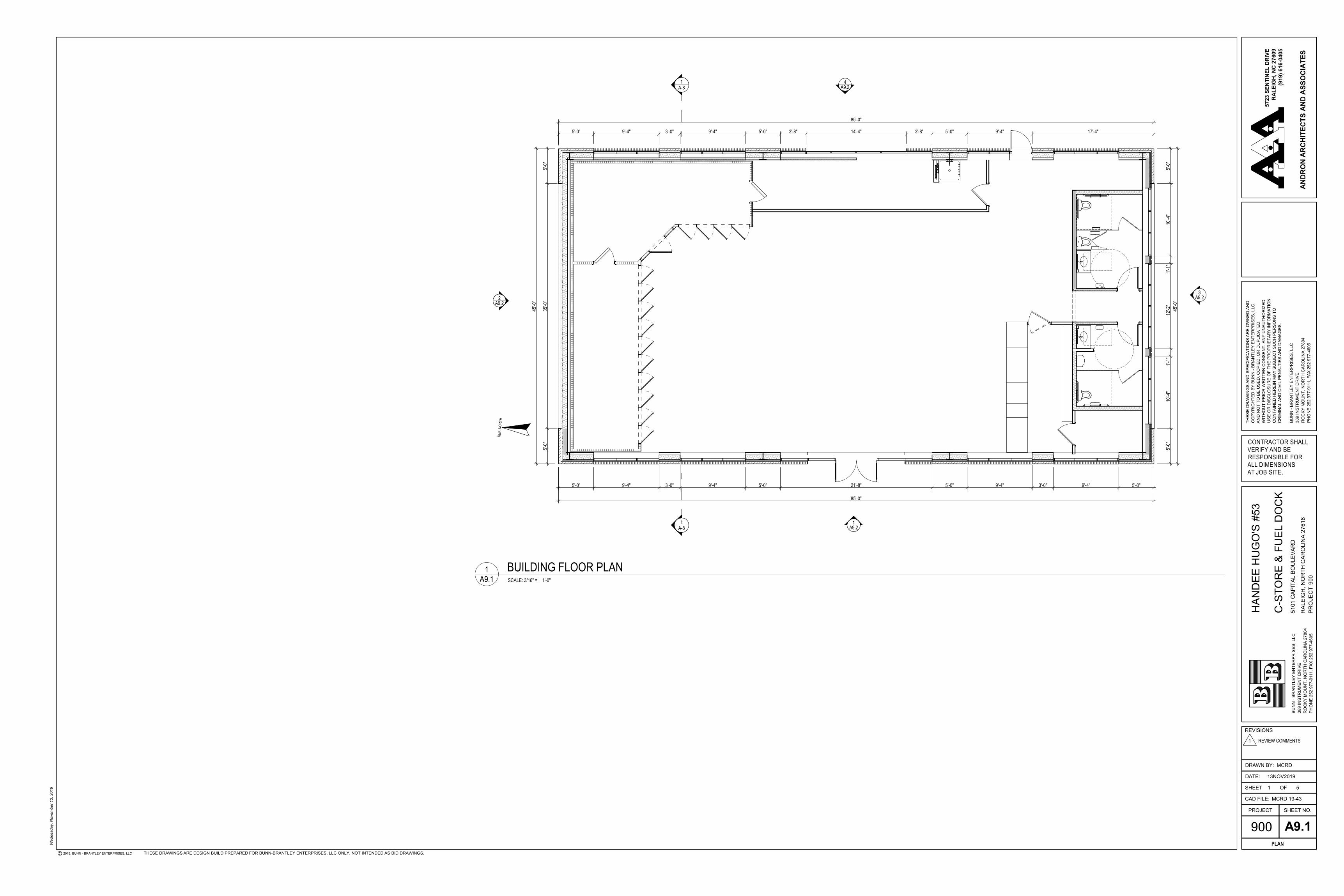
The applicant is requesting an administrative alternate to the Pedestrian Access requirements for the proposed gas station on a 1.01-acre property zoned Industrial Mixed-use, 3 Stories, Parking Limited Frontage (IX-3-PL). For Parking Limited Frontage, one entrance per building is required along the primary street. The applicant is providing an entrance along only one primary street, Capital Boulevard, but not on the Spring Forest Road façade. An entrance is provided on the western façade facing the gas pumps that will be visible from Spring Forest Road and directly accessible via a sidewalk. Both entrances are enhanced to be clearly visible from the two rights-of-way.
Additional UDO Sections: Sec. 3.4.5.F Parking Limited Frontage F. Pedestrian Access F1. Primary street-facing entrance required yes F2. Direct pedestrian access is required from the public sidewalk to the primary
street-facing entrance of the building
Administrative Alternate Findings: Sec. 1.5.8. Administrative Alternate Findings
The Planning and Development Officer may in accordance with Sec. 10.2.17. allow a non-street-facing entrance, subject to all of the following findings: 1. The approved alternate meets the intent of the street-facing entrance
regulations; 2. The approved alternate conforms with the Comprehensive Plan and adopted
City plans; 3. The pedestrian access point is easily identifiable by pedestrian, customer,
and visitors;
4. Recessed or projecting entries or building elements have been incorporated into the design of the building to enhance visibility of the street-facing entrance; and
5. The pedestrian route from the street and bus stops and other modes of public transportation to the entrance is safe, convenient and direct.
Comprehensive Plan Guidance: Policy LU 2.1 - Placemaking Development within Raleigh’s jurisdiction should strive to create places, streets,
and spaces that in aggregate meet the needs of people at all stages of life, are visually attractive, safe, accessible, functional, inclusive have their own identity, and maintain or improve local character. Policy LU 2.2 – Compact Development New Development and redevelopment should use a more compact land use pattern to support the efficient provision of public services, improve the performance of transportation networks, preserve open space, and reduce the negative impacts of low intensity and non-contiguous development. Policy LU 2.5 – Healthy Communities New development, redevelopment, and infrastructure investment should strive to promote healthy communities and active lifestyles by providing or encouraging enhanced bicycle and pedestrian circulation, access, and safety along roads near areas of employment, schools, libraries, and parks. Policy LU 4.5 – Connectivity New development and redevelopment should provide pedestrian and vehicular connectivity between individual development sites to provide alternative means of access along corridors. Policy LU 5.1 – Reinforcing the Urban Pattern New development should be visually integrated with adjacent buildings, and more generally with the surrounding area. Quality design and site planning is required so that new development opportunities within the existing urban fabric of Raleigh are implemented without adverse impacts on local character and appearance.
Policy LU 7.4 – Scale and Design of New Commercial Uses New uses within commercial districts should be developed at a height, mass, scale, and design that is appropriate and compatible with surrounding areas. Policy LU 7.6 – Pedestrian-friendly Development New and redeveloped commercial and mixed-use developments should be pedestrian-friendly.
Policy T.29 – Curb Cuts The development of curb cuts along public streets—particularly on major streets—should be minimized to reduce vehicular conflicts, increase pedestrian safety, and improve roadway capacity. Policy T 5.10 – Building Orientation All primary building entrances should front onto a publicly accessible, and easily discernible, and ADA-compliant walkway that leads directly from the street to the front door to improve pedestrian access.
Policy UD 1.2 – Architectural Features Quality architecture should anchor and define the public realm. Elements of quality architecture include architectural accents and features conducive to pedestrian scale and usage, such as a distinct base, middle, and top (for high-rise buildings); vertical and horizontal articulation; rooflines that highlight entrances; primary entrances on the front façade; transparent storefront windows and activated uses on the ground floor; and corner buildings with defining landmark features. Policy UD 1.3 – Creating Attractive Facades Well-designed building facades, storefront windows, and attractive signage and lighting should be used to create visual interest. Monolithic or box-like facades should be avoided to promote the human quality of the street. Policy UD 1.4 – Maintaining Facade Lines Maintain the established facade lines of neighborhood streets by aligning the front walls of new construction with the prevailing facades of adjacent buildings, unless doing so results in substandard sidewalks. Avoid violating this pattern by placing new construction in front of the historic facade line unless the streetscape is already characterized by such variations. Where existing facades are characterized by recurring placement of windows and doors, new construction should complement the established rhythm.
Policy UD 2.3 – Activating the Street New retail and mixed-use centers should activate the pedestrian environment of the street frontage in addition to internal pedestrian networks and connections, particularly along designated Main Street corridors. Policy UD 3.4 – Enhanced Sidewalks Promote a higher standard of storefront design and architectural detail in downtown and along the city’s Main Street corridors. Along walkable shopping streets, create streetwalls with relatively continuous facades built to the front lot line to provide a sense of enclosure and improve pedestrian comfort. Policy UD 4.2 – Streets as Public Spaces Design streets as the main public spaces scaled for pedestrian use within City Growth, TOD, and Mixed-use Centers as designated on the Urban Form Map. Policy UD 4.5 – Improving the Street Environment Create attractive and interesting commercial streetscapes by promoting ground level retail and desirable street activities, making walking more comfortable and convenient, ensuring that sidewalks are wide enough to accommodate pedestrian traffic, minimizing curb cuts and driveways, and avoiding windowless facades and gaps in the street wall. Policy UD 4.6 – Activated Public Space Provide urban squares, public plazas, and similar areas that stimulate vibrant pedestrian street life and provide a focus for community activities. Encourage the “activation” of such spaces through the design of adjacent structures; for example, through the location of shop entrances, window displays, awnings, and outdoor dining areas.
Policy UD 6.2 – Ensuring Pedestrian Comfort and Convenience Promote a comfortable and convenient pedestrian environment by requiring that buildings face the sidewalk and street area, avoid excessive setbacks, and
provide direct pedestrian connections. On-street parking should be provided along pedestrian-oriented streets and surface parking should be to the side or in the rear. This should be applied in new development, wherever feasible, especially on Transit Emphasis and Main Street corridors and in mixed-use centers. Policy UD 7.3 – Design Guidelines The Design Guidelines in Table UD-1 shall be used to review rezoning petitions and development applications for mixed-use developments; or rezoning petitions and development applications along Main Street and Transit emphasis corridors or in City Growth, TOD, and Mixed-Use centers, including preliminary site plans and development plans, petitions for the application of the Pedestrian Business or Downtown Overlay Districts, Planned Development Districts and Conditional Use zoning petitions.
UDG 1 - All mixed-use developments should generally provide retail (such as eating establishments, food stores, and banks), and other uses such as office and residential within walking distance of each other. Mixed uses should be arranged in a compact and pedestrian-friendly form. UDG 6 – A primary task of all urban architecture and landscape design is the physical definition of streets and public spaces as places of shared used. Streets should be lined by buildings rather than parking lots and should provide interest especially for pedestrians. Garage entrances and/or loading areas should be located at the side or rear of a property.
UDG 18 – Convenient, comfortable pedestrian access between the transit stop and the building entrance should be planned as part of the overall pedestrian network. UDG 25 – The primary entrance should be both architecturally and functionally on the front facade of any building facing the primary public street. Such entrances should be designed to convey their prominence on the fronting facade. UDG 26 – The ground level of the building should offer pedestrian interest along sidewalks. This includes windows, entrances, and architectural details. Signage, awnings, and ornamentation are encouraged. UDG 27 – The sidewalks should be the principal place of pedestrian movement and casual social interaction. Designs and uses should be complementary to that function.
HANDEE HUGOS #53 – CAPITAL BLVD > BNB-19010
2905 Meridian Parkway, Durham, NC 27713 / 919. 361. 5000 creating experiences through experience
January 27, 2020 City of Raleigh – Urban Design Center One Exchange Plaza – Suite 100 Raleigh, NC 27601 Re: Administrative Design Alternate Findings Pedestrian Access:
1. The approved alternate meets the intent of the street-facing entrance regulations; McAdams Response: Pedestrian access will be provided out to Capital Boulevard with a street-facing entrance, as well as to the rear parking area and canopy. Sidewalk access has been provided to Spring Forest, and the intent of the ordinance has been met by providing clear building access along both ROWs. The building is also oriented on site in such a way that the main entrance from the parking area is clearly visible from Spring Forest Road.
2. The approved alternate conforms with the Comprehensive Plan and adopted City plans; McAdams Response: Proposed redevelopment meets the Comprehensive Plan and other adopted City plans. Redevelopment of the site will increase pedestrian accessibility, add more open space and amenity areas, as well as provide an updated building that is more in line with the intent of the UDO. The building will be pulled closer to the street with all vehicular access and parking in the rear.
3. The pedestrian access point is easily identifiable by pedestrians, customer, and visitors; McAdams Response: Pedestrian access from both ROW will be clearly identifiable and easily accessible from existing sidewalk.
4. Recessed or projecting entries or building elements have been incorporated into the design of the building to enhance visibility of the street-facing entrance; and
McAdams Response: Building elements enhance entrances and are clearly visible from the ROW. 5. The pedestrian route from the street and bus stops and other modes of public transpiration to the entrance
is safe, convenient and direct. McAdams Response: Access is very direct from both ROW via sidewalk connections to the existing sidewalk.
Build-to:
1. The approved alternate meets the intent of the build-to regulations; McAdams Response: Building as proposed meets the intent of the ordinance. Due to the building SF and use our building is pulled as close to the street as possible and cannot meet the additional primary build-to along Spring Forest. The proposed design does meet the build-to along this corridor as secondary, but due to the size of the building cannot meet two primary build-to lengths.
HANDEE HUGOS #53 – CAPITAL BLVD > BNB-19010
2905 Meridian Parkway, Durham, NC 27713 / 919. 361. 5000 creating experiences through experience
2. The approved alternate conforms with the Comprehensive Plan and adopted City plans; McAdams Response: Proposed redevelopment conforms to the Comprehensive Plan and other City plans, the proposed building is within the build-to area of both corridors and meets the intent of the ordinance.
3. The approved alternate does not substantially negatively alter the character-defining street wall or establish a build-to pattern that is not harmonious with the existing built context;
McAdams Response: The proposed building is within the build-to area of both corridors. The designation of Spring Forest as a second primary street requires double the building depth which is not feasible for redevelopment on this site. The proposed building location is pulled to the street and meets the intent of the build-to pattern.
4. The change in percentage of building that occupies the build-to area or increased setback does not negatively impact pedestrian access, comfort or safety; and
McAdams Response: The percentage along Spring Forest being less than 50% does not negatively impact pedestrian access, comfort or safety. The redevelopment increases all of the above and meets the intent of the build-to requirement.
5. Site area that would have otherwise been occupied by buildings is converted to an outdoor amenity area under Sec. 1.5.3.B.
McAdams Response: The area along Spring Forest within the reduced built-to width will be redeveloped with an ADA-accessible amenity area which will include landscaped areas and a picnic table, and sidewalk access to the ROW and building.
Based on the findings outlined we feel the redevelopment of this site meets the intent of the Unified Development Ordinance with regards to both build-to requirements and pedestrian access. We respectfully request approval of a design alternate for this development based on the above findings.
Sincerely, MCADAMS
C2.00
BNB19010-ASR-S1.dwg
1"=20'
CLIENT
REVISIONS
PROJECT NO. BNB-19010
FILENAME
CHECKED BY
DRAWN BY
SCALE
DATE 11. 26. 2019
N0. DATE
X:\P
roje
cts\
BNB\
BNB-
1901
0\04
-Pro
duct
ion\
Engi
neer
ing\
Cons
truc
tion
Draw
ings
\Cur
rent
Dra
win
gs\B
NB1
9010
-ASR
-S1.
dwg,
11/
26/2
019
2:32
:39
PM, E
lling
ton,
Tha
d
The John R. McAdams Company, Inc.2905 Meridian Parkway
Durham, NC 27713
phone 919. 361. 5000fax 919. 361. 2269
license number: C-0293
www.mcadamsco.com
HAN
DEE
HUG
O'S
#53
ADM
INIS
TRAT
IVE
SITE
PLA
N51
01 C
APIT
AL B
OU
LEVA
RDRA
LEIG
H, N
ORT
H CA
ROLI
NA,
276
16
SHEET
PLAN INFORMATION
BUNN BRANTLEY ENTERPRISES, LLC389 INSTRUMENT DRIVEROCKY MOUNT, NC 27804PHONE: 252. 977. 9111
PRELIMINARY DRAWING - NOT RELEASED FOR CONSTRUCTION
1 11. XX. 2019 RESPONSE TO 1ST ROUND COMMENTS
EXISTING
CAPITAL BLVD - US 1
(200' PUBLIC R/W
)
(126' ULTIM
ATE ROW
)CLASSIFICATIO
N: BO
ULEVARD
EXISTING: 3 LAN
ES NO
RTHBOU
ND
3 LANES SO
UTHBO
UN
D-2 LEFT TURN
LANES-1 RIGHT TU
RN LAN
E
POSTED SPEED LIM
IT 45 MPH
EXISTINGSPRING FOREST RD(SR2041)
(120' PUBLIC R/W)(104' ULTIMATE ROW)
CLASSIFICATION: AVENUE, 4 LANE DIVIDEDEXISTING: 2 LANES WESTBOUND
2 LANES EASTBOUND-2 LEFT TURN LANESPOSTED SPEED LIMIT 45 MPH
BUILDING
3,825 SF
GRAPHIC SCALE0 10 20 40
1 inch = 20 ft.
ALL CONSTRUCTION SHALL CONFORM WITH THE LATESTVERSION OF THE CITY OF RALEIGH AND NCDOT STANDARDS,SPECIFICATIONS AND DETAILS.
SITE PLAN
TRE
RW
SITE LEGEND
GENERAL NOTES:1. ALL DIMENSIONS AND GRADES SHOWN ON THE PLANS SHALL BE FIELD VERIFIED BY THE
CONTRACTOR PRIOR TO CONSTRUCTION. CONTRACTOR SHALL NOTIFY THE OWNER IF ANYDISCREPANCIES EXIST PRIOR TO PROCEEDING WITH CONSTRUCTION FOR NECESSARY PLANOR GRADE CHANGES. NO EXTRA COMPENSATION SHALL BE PAID TO THE CONTRACTOR FORANY WORK DONE DUE TO DIMENSIONS OR GRADES SHOWN INCORRECTLY ON THESE PLANSIF SUCH NOTIFICATION HAS NOT BEEN GIVEN.
2. THERE MAY BE WETLANDS WITHIN THIS SITE. IT IS THE OWNER'S RESPONSIBILITY FORWETLANDS JURISDICTION AND PERMIT DISTURBANCE PRIOR TO ANY GRADING ACTIVITY.
3. DRIVEWAYS MAY INTERSECT A STREET NO CLOSER THAN 50' FROM THE INTERSECTION OF 2STREET RIGHTS-OF-WAY, NOT INCLUDING AN ALLEY.
4. ALL HC RAMPS TO BE FIELD ADJUSTED WITH INPUT FROM THE CITY OF RALEIGH FIELDINSPECTOR PRIOR TO INSTALLATION.
5. IF IN THE FIELD POWER POLES CONFLICT WITH THE LOCATED HC RAMPS THE CONTRACTORIS TO RELOCATE THE POWER POLE TO UTILITY COMPANY APPROVED LOCATION.
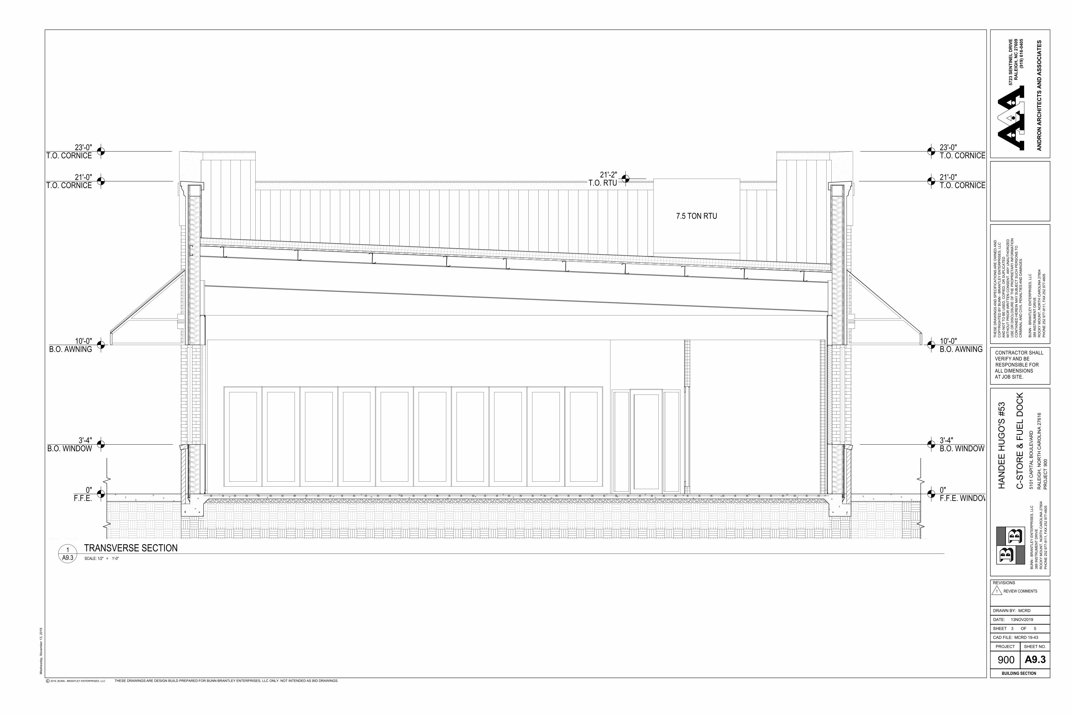
CITY OF RALEIGH NOTES:1. SEE BUILDING SECTION (9.3)
2. HVAC UNITS AND COMPRESSORS ON ROOF SCREENED BY PARAPET.
PARKING DATA
MUTCD R1-130"x30"
MUTCD R7-8A
SIGNAGE LEGEND
OUTDOOR AMENITY REQUIREMENTS:TOTAL SITE ACREAGE: 44,101 SQFTOUTDOOR AMENITY REQUIRED: 4,410 SQFTOUTDOOR AMENITY PROVIDED: 5,023 SQFT
SEE SHEET C0.01 FOR ALL PROJECT SITE, GRADING, STORMDRAINAGE AND UTILITY NOTES.
PARKING REQUIRED 1 SPACE/300 SF OF GROSS AREA
3,825 SF /300 = 13 SPACES 12 SPACES 1 ADA ACCESSIBLE SPACESPROPOSED 16 TOTAL SPACES
BICYCLE PARKING REQUIRED (MINIMUM) SHORT TERM: 1 SPACE PER 5,000 SFOF GROSS FLOOR AREA, 4 MINIMUM LONG TERM: NONEBICYCLE PARKING PROVIDED SHORT TERM: 4 LONG TERM: NONE
1
1
1
1
1
1
1
1
1
1
EXISTING ROAD NOTES / CLASSIFICATION /ULTIMATE RIGHT-OF-WAY:1. SPRING FOREST ROAD-SR2041 IS A 4 LANE DIVIDED ROAD WITH 120' WIDTH PUBLIC R/W.
EXISTING CONFIGURATION IS 2 LANES EAST BOUND WITH 2 LEFT TURN LANES AND ONESTRAIGHT/RIGHT LANE, 2 LANES WEST BOUND. IMAPS FORMER CLASSIFICATION MAJORTHOROUGHFARE, STREET TYPE AVENUE 6-LANE DIVIDED .
2. CAPITAL BOULEVARD-US 1 IS A 6 LANE DIVIDED ROAD WITH 200' WIDTH PUBLIC R/W.EXISTING CONFIGURATION IS 3 LANES SOUTHBOUND, 3 LANES NORTHBOUND WITH 1 RIGHTTURN LANE AND 2 LEFT TURN LANES AND CONCRETE ISLAND. IMAPS FORMERCLASSIFICATION PRINCIPLE ARTERIAL, STREET TYPE AVENUE 6-LANE DIVIDED .
1
1
BUILD - TO REQUIREMENTS· PRIMARY STREET DESIGNATION = CAPITAL BLVD· SIDE STREET DESIGNATION = SPRING FOREST ROAD· PRIMARY STREET BUILD TO:
MINIMUM = 3'MAXIMUM = 100'
· BUILDING WIDTH IN PRIMARY BUILD-TO FRONTAGE 85'MINIMUM = 50%PROVIDED = 100%
· SIDE STREET BUILD-TOMINIMUM = 0'MAXIMUM = 100'
· BUILDING WIDTH IN SIDE BUILD-TO FRONTAGE 45'MINIMUM = 25%PROVIDED = 72%
1
(6) PUMP ISLANDS
W/ CANOPY
HAN-DEE HUGO’S
CONVENIENCE STORE
SPRING FOREST ROAD
CA
PITA
L BO
ULEV
AR
D
SPRING FOREST ROAD BUILD-TO-AREA
RIGHT OF WAY LENGTH 233 LINEAR FEET
PROPOSED BUILDING 45 LF/19%
PROPOSED AMENITY AREAS 159.7 LF/69%
COMBINED BLDG AND AMENITY 204.7 LF/88%
233 LF OF ROW
100
’
100’
AMENITY AREA - 139’BUILDING - 45’
AMENITY AREA - 20.7’
February 14,
2020HAN-DEE HUGO’S CAPITAL BOULEVARD
RALEIGH, NORTH CAROLINA SITE PLANP
01
SCALE: 1”= 20’
N
CLIENT
REVISIONS
PROJECT NO. BNB-19010
FILENAME
CHECKED BY
DRAWN BY
SCALE
DATE 11. 26. 2019
N0. DATE
X:\P
roje
cts\
BNB\
BNB-
1901
0\04
-Pro
duct
ion\
Engi
neer
ing\
Cons
truc
tion
Draw
ings
\Cur
rent
Dra
win
gs\B
NB1
9010
-ASR
-LS1
.dw
g, 1
1/26
/201
9 2:
33:1
8 PM
, Elli
ngto
n, T
had
The John R. McAdams Company, Inc.2905 Meridian Parkway
Durham, NC 27713
phone 919. 361. 5000fax 919. 361. 2269
license number: C-0293
www.mcadamsco.com
HAN
DEE
HUG
O'S
#53
ADM
INIS
TRAT
IVE
SITE
PLA
N51
01 C
APIT
AL B
OU
LEVA
RDRA
LEIG
H, N
ORT
H CA
ROLI
NA,
276
16
SHEET
PLAN INFORMATION
BUNN BRANTLEY ENTERPRISES, LLC389 INSTRUMENT DRIVEROCKY MOUNT, NC 27804PHONE: 252. 977. 9111
PRELIMINARY DRAWING - NOT RELEASED FOR CONSTRUCTION
GRAPHIC SCALE0 10 20 40
1 inch = 20 ft.
ALL CONSTRUCTION SHALL CONFORM WITH THE LATESTVERSION OF THE CITY OF RALEIGH AND NCDOT STANDARDS,SPECIFICATIONS AND DETAILS.
1 11. XX. 2019 RESPONSE TO 1ST ROUND COMMENTS
L5.00
BNB19010-ASR-LS1.dwg
1"=20'
LANDSCAPE PLAN
AAL
SRD
LANDSCAPE CALCULATIONSSTREET TREES
CAPITAL BLVD 144 LF
TREESREQUIRED: 4 (1/40 LF)PROVIDED: 4
SPRING FOREST RD 193 LF
TREESREQUIRED: 0 (TYPE C2 STREET PROTECTIVE YARD
TO BE INSTALLED IN LIEU OF STREET TREES)
TYPE C2 STREET PROTECTIVE YARD
SPRING FOREST RD 193 LFSHADE TREES
REQUIRED: 8(4/100 LF)PROVIDED: 8 (5 EXISTING)
SHRUBSREQUIRED: 30(15/100 LF)PROVIDED: 36
VEHICLE USE AREA
PARKING AREA 2,266 SF
SHADE TREESREQUIRED: 2 (1/2000 SF)PROVIDED: 2
GENERAL LANDSCAPE NOTES:1. ALL MATERIALS AND METHODS OF CONSTRUCTION SHALL BE IN ACCORDANCE WITH THE CITY OF RALEIGH
AND THE STATE OF NORTH CAROLINA STANDARDS AND SPECIFICATIONS.
2. CONTRACTOR IS RESPONSIBLE FOR THE SITE INSPECTION BEFORE LANDSCAPE CONSTRUCTION ANDINSTALLATION IN ORDER TO BECOME FAMILIAR WITH THE EXISTING CONDITIONS.
3. LANDSCAPE CONTRACTOR IS RESPONSIBLE FOR LOCATING ALL UNDERGROUND UTILITIES BEFOREBEGINNING DEMOLITION OR INSTALLATION.
4. CONTRACTOR SHALL NOTIFY LANDSCAPE ARCHITECT OF ANY DISCREPANCIES BETWEEN THE NOTES,SPECIFICATIONS, DRAWINGS OR SITE CONDITIONS FOR RESOLUTION PRIOR TO INSTALLATION.
5. ANY DAMAGE TO UTILITIES SHALL BE REPAIRED AT THE CONTRACTOR'S EXPENSE.
6. THIS PLAN IS FOR PLANTING PURPOSES ONLY. FOR INFORMATION REGARDING BUILDINGS, GRADING,WALLS, ETC., REFER TO ARCHITECTURE, SITE AND GRADING PLANS.
7. VERIFICATION OF TOTAL PLANT QUANTITIES AS SHOWN IN THE PLANT SCHEDULE SHALL BE THERESPONSIBILITY OF THE LANDSCAPE CONTRACTOR. ANY DISCREPANCIES SHALL BE BROUGHT TO THEATTENTION OF THE LANDSCAPE ARCHITECT.
8. CONTRACTOR TO ENSURE PROPER STABILIZATION AND SEEDING OF THE SITE IN ACCORDANCE WITHAPPLICABLE REGULATIONS.
9. LANDSCAPE MATERIAL SHALL BE WELL FORMED, VIGOROUS, GROWING SPECIMENS WITH GROWTHTYPICAL OF VARIETIES SPECIFIED AND SHALL BE FREE FROM DAMAGE, INSECTS AND DISEASES. MATERIALSHALL EQUAL OR SURPASS #1 QUALITY AS DEFINED IN THE CURRENT ISSUE OF “AMERICAN STANDARDFOR NURSERY STOCK” AS PUBLISHED BY THE AMERICAN NURSERY & LANDSCAPE ASSOCIATION.
10. ALL PLANT MATERIAL IS TO BE CAREFULLY HANDLED BY THE ROOT BALL, NOT THE TRUNK, BRANCHESAND/OR FOLIAGE OF THE PLANT. MISHANDLED PLANT MATERIAL MAY BE REJECTED BY THE LANDSCAPEARCHITECT.
11. ALL PLANT MATERIAL IS TO BE WELL ROOTED, NOT ROOT BOUND, SUCH THAT THE ROOT BALL REMAINSINTACT THROUGHOUT THE PLANTING PROCESS. DEFICIENT PLANT MATERIAL MAY BE REJECTED BY THELANDSCAPE ARCHITECT OR OWNER.
12. ALL PLANTS TO BE A MINIMUM OF WHAT IS SPECIFIED IN THE PLANT SCHEDULE. ANY CHANGES ORSUBSTITUTIONS SHALL BE APPROVED BY THE LANDSCAPE ARCHITECT AND GOVERNING JURISDICTIONPRIOR TO ANY HOLE BEING DUG.
13. CONTRACTOR TO COORDINATE WITH OWNER'S REPRESENTATIVE AND LANDSCAPE ARCHITECT TOESTABLISH THE EXTENTS OF MULCH/SEED/SOD IF NOT SPECIFICALLY SHOWN ON PLANS.
14. CONTRACTOR SHALL PROVIDE POSITIVE DRAINAGE IN ALL PLANTING AREAS.
15. PROPOSED TREES TO BE PLANTED A MINIMUM 20 FEET FROM ANY LIGHT POLE AS MEASURED FROMTRUNK OF THE TREE TO THE POLE.
16. PROPOSED TREES TO BE PLANTED A MINIMUM 10 FEET FROM ANY FIRE HYDRANT AS MEASURED FROMTRUNK OF THE TREE TO THE HYDRANT.
17. CONTRACTOR SHALL COMPLETE SOIL TEST IN ALL PLANTING AREAS TO DETERMINE SOIL AMENDMENTREQUIREMENTS UNLESS WAIVED BY OWNER'S REPRESENTATIVE. CONTRACTOR SHALL ADJUST PH ANDFERTILITY BASED UPON THE SOIL TEST RESULTS.
18. TOPSOIL SHALL BE FREE OF MATERIAL LARGER THAN 1.0 INCH IN DIAMETER OR LENGTH AND SHALL NOTCONTAIN SLAG, CINDERS, STONES, LUMPS OF SOIL, STICKS, ROOTS, TRASH, OR OTHER EXTRANEOUSMATERIAL.
19. LOOSEN SUBGRADE / SURFACE SOIL TO A MINIMUM DEPTH OF 6 INCHES. APPLY SOIL AMENDMENTS ANDFERTILIZERS AS REQUIRED BY THE SOIL TEST RESULTS TO ACHIEVE A HEALTHY GROWING MEDIA AND MIXTHOROUGHLY INTO TOP 4 INCHES OF SOIL. SPREAD PLANTING SOIL MIX TO A DEPTH OF 6 INCHES BUTNOT LESS THAN REQUIRED TO MEET FINISH GRADES AFTER NATURAL SETTLEMENT. DO NOT SPREAD IFPLANTING SOIL OR SUBGRADE IS FROZEN, MUDDY, OR EXCESSIVELY WET.
20. IF IMPORTED TOPSOIL IS REQUIRED, THE SUBGRADE SHALL BE SCARIFIED OR TILLED TO A DEPTH OF ATLEAST 6 INCHES PRIOR TO INSTALLATION OF IMPORTED TOPSOIL. FOLLOWING INSTALLATION OFIMPORTED TOPSOIL, THE TOPSOIL SHALL BE TILLED TO INTEGRATE THE SOIL PROFILES.
21. PLANT MATERIALS ARE TO BE GUARANTEED FOR A PERIOD OF 12 MONTHS. PLANT MATERIALS WHICHREMAIN UNHEALTHY WILL BE REPLACED BY THE LANDSCAPE CONTRACTOR BEFORE THE EXPIRATION OFTHE GUARANTEE PERIOD OR IMMEDIATELY IF SO DIRECTED BY THE OWNER'S REPRESENTATIVE ORLANDSCAPE ARCHITECT.
22. ALL TREE PLANTINGS SHALL BE MULCHED WITH SHREDDED HARDWOOD MULCH IN NATURAL COLOR TO ADEPTH OF 3 INCHES, AND WITH A MINIMUM 3 FOOT RADIUS FROM BASE OF TREE OR TO DRIPLINE.MULCH SHALL BE FREE OF TRASH AND MAINTAINED WEED FREE. MULCH SHALL NOT COVER THE ROOTFLARE. CONFIRM MULCH SPECIFICATIONS WITH OWNER'S REPRESENTATIVE OR LANDSCAPE ARCHITECT.
23. DO NOT PRUNE TREES AND SHRUBS BEFORE DELIVERY. PROTECT BARK, BRANCHES, AND ROOT SYSTEMSFROM SUN SCALD, DRYING, SWEATING, WHIPPING, AND OTHER HANDLING AND TYING DAMAGE. DONOT BEND OR BIND-TIE TREES OR SHRUBS IN SUCH A MANNER AS TO DESTROY THEIR NATURAL SHAPE. PROVIDE PROTECTIVE COVERING OF EXTERIOR PLANTS DURING DELIVERY. DO NOT DROP EXTERIORPLANTS DURING DELIVERY AND HANDLING.
24. DELIVER EXTERIOR PLANTS AFTER PREPARATIONS FOR PLANTING HAVE BEEN COMPLETED AND INSTALLIMMEDIATELY. IMMEDIATELY AFTER UNLOADING, STAND THE TREES UP TO REDUCE THE RISK OF SUNSCALD. PROPERLY STAGED TREES ARE STANDING, UNTIED AND SPACED. UNLESS IMMEDIATELY INSTALLED,SET EXTERIOR PLANTS AND TREES IN SHADE, PROTECT FROM WEATHER AND MECHANICAL DAMAGE, ANDKEEP ROOTS MOIST.
25. SEE LANDSCAPE DETAILS FOR TREE STAKING REQUIREMENTS.
26. EXCAVATE EDGES OF ALL PLANTING BEDS TO 2 INCH DEPTH TO FORM A NEAT AND CRISP DEFINITION.
27. CONTRACTOR SHALL REMOVE DEBRIS AND FINE GRADE ALL PLANTING AREAS PRIOR TO INSTALLATION.
28. REMOVE GUY WIRES AND STAKES AT END OF WARRANTY PERIOD OR ESTABLISHMENT.
29. FINISH GRADING: GRADE PLANTING AREAS TO A SMOOTH, UNIFORM SURFACE PLANE WITH LOOSE,UNIFORMLY FINE TEXTURE. GRADE TO WITHIN PLUS OR MINUS 1/2 INCH OF FINISH ELEVATION. ROLLAND RAKE, REMOVE RIDGES, AND FILL DEPRESSIONS TO MEET FINISH GRADES. LIMIT FINISHED GRADINGTO AREAS THAT CAN BE PLANTED IN THE IMMEDIATE FUTURE.
30. EXISTING TREE AND SHRUB LOCATIONS TO BE VERIFIED IN FIELD PRIOR TO CONSTRUCTION, TREES SHALLBE PROTECTED WITH TREE PROTECTION FENCING AT THE DRIP LINE PER THE TREE PROTECTION DETAIL.CONTRACTOR TO COORDINATE ANY CONFLICTS WITH THE LANDSCAPE ARCHITECT.
31. EXISTING SHRUBS NOT SHOWN ON PLAN SHALL REMAIN UNLESS OTHERWISE DIRECTED.
SHRUB INSTALLATION DETAILN.T.S.
EXISTING
CAPITAL BLVD - US 1
(200' PUBLIC R/W
)
(126' ULTIM
ATE ROW
)
EXISTINGSPRING FOREST RD(SR2041)
(120' PUBLIC R/W)(104' ULTIMATE ROW)
BUILDING
3,825 SF1
1
1
1
1
1
GSPublisherVersion 1070.5.13.96
900
13NOV2019
MCRD 19-43
BUN
N -
BRAN
TLEY
EN
TER
PRIS
ES, L
LC
PHO
NE
252
977-
9111
, FAX
252
977
-460
5R
OC
KY M
OU
NT,
NO
RTH
CAR
OLI
NA
2780
438
9 IN
STR
UM
ENT
DR
IVE
RAL
EIG
H, N
OR
TH C
ARO
LIN
A 27
616
900
5101
CAP
ITAL
BO
ULE
VAR
D
SHEET NO.
SHEET
CAD FILE:
PROJECT
DRAWN BY:
DATE:
REVISIONS
RESPONSIBLE FORALL DIMENSIONSAT JOB SITE.
CONTRACTOR SHALLVERIFY AND BE
BUN
N -
BRAN
TLEY
EN
TER
PRIS
ES, L
LC
THES
E D
RAW
ING
S AN
D S
PEC
IFIC
ATIO
NS
ARE
OW
NED
AN
D
WIT
HO
UT
PRIO
R W
RIT
TEN
CO
NSE
NT.
AN
Y U
NAU
THO
RIZ
ED
CO
NTA
INED
HER
EIN
MAY
SU
BJEC
T SU
CH
PER
SON
S TO
USE
OR
DIS
CLO
SUR
E O
F TH
E PR
OPR
IETA
RY
INFO
RM
ATIO
N
CO
PYR
IGH
TED
BY
BUN
N -
BRAN
TLEY
EN
TER
PRIS
ES, L
LCAN
D N
OT
TO B
E U
SED
, CO
PIED
, OR
DU
PLIC
ATED
CR
IMIN
AL A
ND
CIV
IL P
ENAL
TIES
AN
D D
AMAG
ES.
PHO
NE
252
977-
9111
, FAX
252
977
-460
5R
OC
KY M
OU
NT,
NO
RTH
CAR
OLI
NA
2780
438
9 IN
STR
UM
ENT
DR
IVE
HAN
DEE
HU
GO
'S #
53
C-S
TOR
E &
FUEL
DO
CK
MCRD
A9.1PLAN
OF
5723
SEN
TIN
EL D
RIV
ER
ALE
IGH
, NC
276
09(9
19) 6
16-0
405
ANDR
ON
ARCH
ITEC
TS A
ND A
SSO
CIAT
ES
Wed
nesd
ay, N
ovem
ber 1
3, 2
019
2019, BUNN - BRANTLEY ENTERPRISES, LLC
PRO
JEC
T
THESE DRAWINGS ARE DESIGN BUILD PREPARED FOR BUNN-BRANTLEY ENTERPRISES, LLC ONLY. NOT INTENDED AS BID DRAWINGS.
1 5
1 REVIEW COMMENTS
REF.
NOR
TH
5'-0" 9'-4" 3'-0" 9'-4" 5'-0" 3'-8" 14'-4" 3'-8" 5'-0" 9'-4" 17'-4"
85'-0"
5'-0"
10'-4
"1'-
1"12
'-2"
1'-1"
10'-4
"5'-
0"45
'-0"
5'-0" 9'-4" 3'-0" 9'-4" 5'-0" 21'-8" 5'-0" 9'-4" 3'-0" 9'-4" 5'-0"
85'-0"
45'-0
"
5'-0"
35'-0
"5'-
0"
1A-8
1A-8
4A9.2
1A9.2
3A9.22
A9.2
SCALE: 3/16" = 1'-0"
1 BUILDING FLOOR PLANA9.1
GSPublisherVersion 1161.1.2.96
900
10JAN2019
MCRD 19-43
BUN
N -
BRAN
TLEY
EN
TER
PRIS
ES, L
LC
PHO
NE
252
977-
9111
, FAX
252
977
-460
5R
OC
KY M
OU
NT,
NO
RTH
CAR
OLI
NA
2780
438
9 IN
STR
UM
ENT
DR
IVE
RAL
EIG
H, N
OR
TH C
ARO
LIN
A 27
616
900
5101
CAP
ITAL
BO
ULE
VAR
D
SHEET NO.
SHEET
CAD FILE:
PROJECT
DRAWN BY:
DATE:
REVISIONS
RESPONSIBLE FORALL DIMENSIONSAT JOB SITE.
CONTRACTOR SHALLVERIFY AND BE
BUN
N -
BRAN
TLEY
EN
TER
PRIS
ES, L
LC
THES
E D
RAW
ING
S AN
D S
PEC
IFIC
ATIO
NS
ARE
OW
NED
AN
D
WIT
HO
UT
PRIO
R W
RIT
TEN
CO
NSE
NT.
AN
Y U
NAU
THO
RIZ
ED
CO
NTA
INED
HER
EIN
MAY
SU
BJEC
T SU
CH
PER
SON
S TO
USE
OR
DIS
CLO
SUR
E O
F TH
E PR
OPR
IETA
RY
INFO
RM
ATIO
N
CO
PYR
IGH
TED
BY
BUN
N -
BRAN
TLEY
EN
TER
PRIS
ES, L
LCAN
D N
OT
TO B
E U
SED
, CO
PIED
, OR
DU
PLIC
ATED
CR
IMIN
AL A
ND
CIV
IL P
ENAL
TIES
AN
D D
AMAG
ES.
PHO
NE
252
977-
9111
, FAX
252
977
-460
5R
OC
KY M
OU
NT,
NO
RTH
CAR
OLI
NA
2780
438
9 IN
STR
UM
ENT
DR
IVE
HAN
DEE
HU
GO
'S #
53
C-S
TOR
E &
FUEL
SER
VIC
E
MCRD
A9.2ELEVATIONS
OF
5723
SEN
TIN
EL D
RIV
ER
ALE
IGH
, NC
276
09(9
19) 6
16-0
405
ANDR
ON
ARCH
ITEC
TS A
ND A
SSO
CIAT
ES
Wed
nesd
ay, F
ebru
ary
12, 2
020
2020, BUNN - BRANTLEY ENTERPRISES, LLC
PRO
JEC
T
THESE DRAWINGS ARE DESIGN BUILD PREPARED FOR BUNN-BRANTLEY ENTERPRISES, LLC ONLY. NOT INTENDED AS BID DRAWINGS.
#LayNoInSubset 23
5'-0" 9'-4" 3'-0" 9'-4" 5'-0" 21'-8" 5'-0" 9'-4" 3'-0" 9'-4" 5'-0"
23'-0" (354.40)
21'-0" (352.40)
0" (331.40)F.F.E.
3'-4" (334.73)
10'-0" (341.40)
20'-0" (351.40)
23'-0" (354.40)
25'-0" (356.40)
85'-0"
1 13
3
34
4
4
23
2
3
2
3
2 3
2
25'-0" (356.40)
21'-0" (352.40)
23'-0" (354.40)
85'-0"
0" (331.40)F.F.E.
3'-4" (334.73)
10'-0" (341.40)
23'-0" (354.40)
5'-0" 9'-4" 3'-0" 9'-4" 5'-0" 3'-8" 14'-4" 3'-8" 5'-0" 9'-4" 3'-0" 9'-4" 5'-0"
6'-8"
9'-4"
3'-0"
8'-0"
12'-0
"
9'-4"
6'-8"
10'-0
"
21'-8"
6'-8"
10'-0
"
14'-4"
9'-4"
6'-8"
9'-4"
6'-8"
4 3
42 3
2
2 2
2
3
3 3
3
3
1
4 1
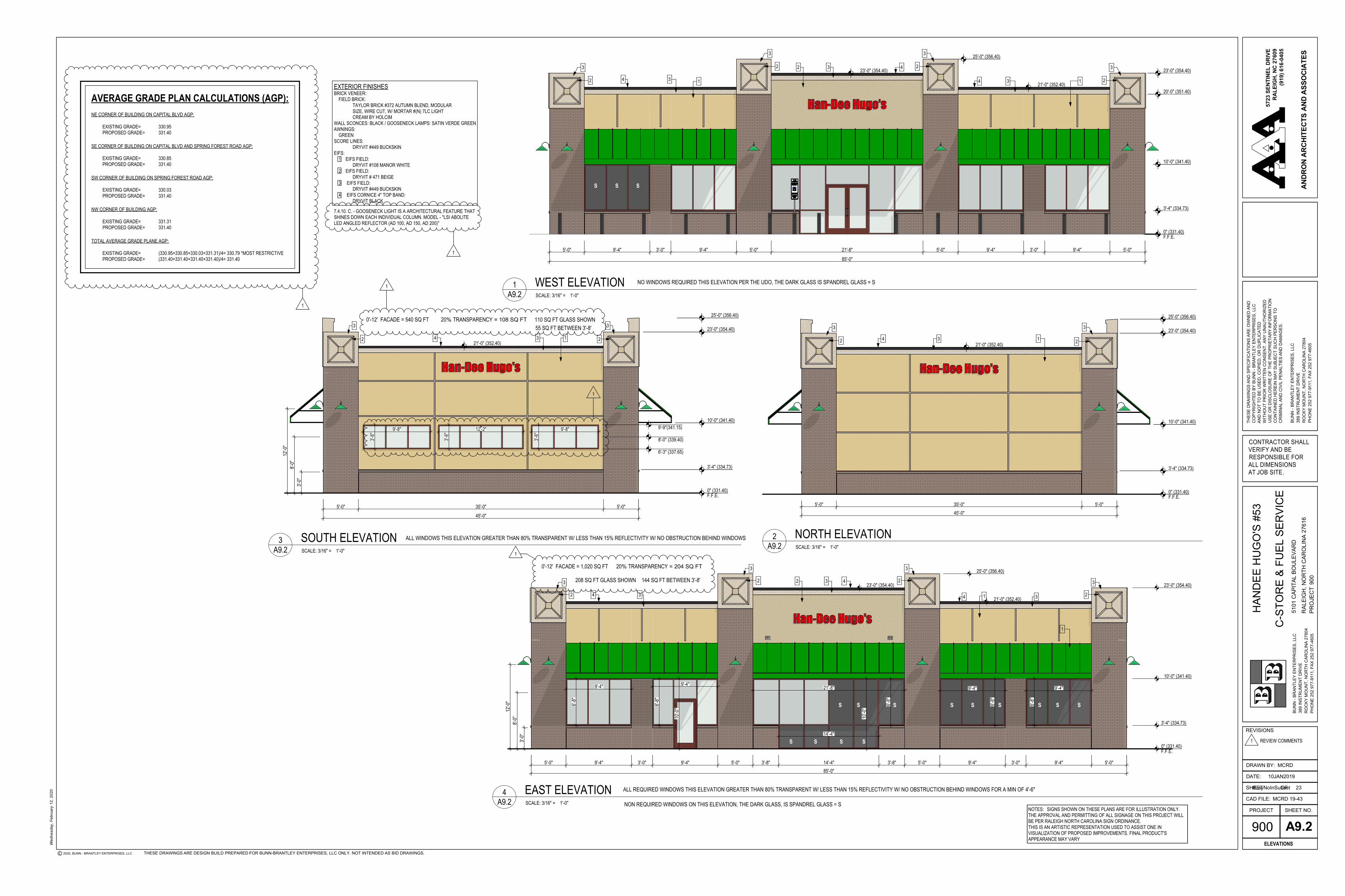
0'-12' FACADE = 1,020 SQ FT 20% TRANSPARENCY = 204 SQ FT
144 SQ FT BETWEEN 3'-8'208 SQ FT GLASS SHOWN
5'-0" 35'-0" 5'-0"
21'-0" (352.40)
0" (331.40)F.F.E.
3'-4" (334.73)
10'-0" (341.40)
23'-0" (354.40)
25'-0" (356.40)
45'-0"
6'-3" (337.65)
8'-0" (339.40)
9'-9"(341.15)9'-8"
3'-6"
12'-2"
3'-6"
3'-6"
9'-8"
3'-0"
8'-0"
12'-0
"
134
3
2
3
2
0'-12' FACADE = 540 SQ FT 20% TRANSPARENCY = 108 SQ FT 110 SQ FT GLASS SHOWN55 SQ FT BETWEEN 3'-8'
45'-0"5'-0" 35'-0" 5'-0"
21'-0" (352.40)
0" (331.40)F.F.E.
3'-4" (334.73)
10'-0" (341.40)
23'-0" (354.40)
25'-0" (356.40)
134
3 3
2 2
EXTERIOR FINISHESBRICK VENEER: FIELD BRICK: TAYLOR BRICK #372 AUTUMN BLEND, MODULAR SIZE, WIRE CUT, W/ MORTAR #(N) 7LC LIGHT CREAM BY HOLCIMWALL SCONCES: BLACK / GOOSENECK LAMPS: SATIN VERDE GREENAWNINGS: GREENSCORE LINES: DRYVIT #449 BUCKSKINEIFS: 1 EIFS FIELD: DRYVIT #108 MANOR WHITE 2 EIFS FIELD: DRYVIT # 471 BEIGE 3 EIFS FIELD: DRYVIT #449 BUCKSKIN 4 EIFS CORNICE 4" TOP BAND: DRYVIT BLACK
AVERAGE GRADE PLAN CALCULATIONS (AGP):NE CORNER OF BUILDING ON CAPITAL BLVD AGP:
EXISTING GRADE= 330.95PROPOSED GRADE= 331.40
SE CORNER OF BUILDING ON CAPITAL BLVD AND SPRING FOREST ROAD AGP:
EXISTING GRADE= 330.85PROPOSED GRADE= 331.40
NW CORNER OF BUILDING AGP:
EXISTING GRADE= 331.31PROPOSED GRADE= 331.40
TOTAL AVERAGE GRADE PLANE AGP:
EXISTING GRADE= (330.95+330.85+330.03+331.31)/4= 330.79 *MOST RESTRICTIVEPROPOSED GRADE= (331.40+331.40+331.40+331.40)/4= 331.40
SW CORNER OF BUILDING ON SPRING FOREST ROAD AGP:
EXISTING GRADE= 330.03PROPOSED GRADE= 331.40
1
1
1
1
1
SCALE: 3/16" = 1'-0"
1 WEST ELEVATIONA9.2
SCALE: 3/16" = 1'-0"
4 EAST ELEVATIONA9.2
SCALE: 3/16" = 1'-0"
3 SOUTH ELEVATIONA9.2 SCALE: 3/16" = 1'-0"
2 NORTH ELEVATIONA9.2
NOTES: SIGNS SHOWN ON THESE PLANS ARE FOR ILLUSTRATION ONLY.THE APPROVAL AND PERMITTING OF ALL SIGNAGE ON THIS PROJECT WILLBE PER RALEIGH NORTH CAROLINA SIGN ORDINANCE.THIS IS AN ARTISTIC REPRESENTATION USED TO ASSIST ONE INVISUALIZATION OF PROPOSED IMPROVEMENTS. FINAL PRODUCT'SAPPEARANCE MAY VARY
7.4.10. C. - GOOSENECK LIGHT IS A ARCHITECTURAL FEATURE THATSHINES DOWN EACH INDIVIDUAL COLUMN. MODEL - "LSI ABOLITELED ANGLED REFLECTOR (AD 100, AD 150, AD 200)"
1 REVIEW COMMENTS
ALL WINDOWS THIS ELEVATION GREATER THAN 80% TRANSPARENT W/ LESS THAN 15% REFLECTIVITY W/ NO OBSTRUCTION BEHIND WINDOWS
NO WINDOWS REQUIRED THIS ELEVATION PER THE UDO, THE DARK GLASS IS SPANDREL GLASS = S
S S S
S S S S
S S S S S S S S S
ALL REQUIRED WINDOWS THIS ELEVATION GREATER THAN 80% TRANSPARENT W/ LESS THAN 15% REFLECTIVITY W/ NO OBSTRUCTION BEHIND WINDOWS FOR A MIN OF 4'-6"
NON REQUIRED WINDOWS ON THIS ELEVATION, THE DARK GLASS, IS SPANDREL GLASS = S
GSPublisherVersion 1070.5.13.96
900
13NOV2019
MCRD 19-43
BUN
N -
BRAN
TLEY
EN
TER
PRIS
ES, L
LC
PHO
NE
252
977-
9111
, FAX
252
977
-460
5R
OC
KY M
OU
NT,
NO
RTH
CAR
OLI
NA
2780
438
9 IN
STR
UM
ENT
DR
IVE
RAL
EIG
H, N
OR
TH C
ARO
LIN
A 27
616
900
5101
CAP
ITAL
BO
ULE
VAR
D
SHEET NO.
SHEET
CAD FILE:
PROJECT
DRAWN BY:
DATE:
REVISIONS
RESPONSIBLE FORALL DIMENSIONSAT JOB SITE.
CONTRACTOR SHALLVERIFY AND BE
BUN
N -
BRAN
TLEY
EN
TER
PRIS
ES, L
LC
THES
E D
RAW
ING
S AN
D S
PEC
IFIC
ATIO
NS
ARE
OW
NED
AN
D
WIT
HO
UT
PRIO
R W
RIT
TEN
CO
NSE
NT.
AN
Y U
NAU
THO
RIZ
ED
CO
NTA
INED
HER
EIN
MAY
SU
BJEC
T SU
CH
PER
SON
S TO
USE
OR
DIS
CLO
SUR
E O
F TH
E PR
OPR
IETA
RY
INFO
RM
ATIO
N
CO
PYR
IGH
TED
BY
BUN
N -
BRAN
TLEY
EN
TER
PRIS
ES, L
LCAN
D N
OT
TO B
E U
SED
, CO
PIED
, OR
DU
PLIC
ATED
CR
IMIN
AL A
ND
CIV
IL P
ENAL
TIES
AN
D D
AMAG
ES.
PHO
NE
252
977-
9111
, FAX
252
977
-460
5R
OC
KY M
OU
NT,
NO
RTH
CAR
OLI
NA
2780
438
9 IN
STR
UM
ENT
DR
IVE
HAN
DEE
HU
GO
'S #
53
C-S
TOR
E &
FUEL
DO
CK
MCRD
A9.3BUILDING SECTION
OF
5723
SEN
TIN
EL D
RIV
ER
ALE
IGH
, NC
276
09(9
19) 6
16-0
405
ANDR
ON
ARCH
ITEC
TS A
ND A
SSO
CIAT
ES
Wed
nesd
ay, N
ovem
ber 1
3, 2
019
2019, BUNN - BRANTLEY ENTERPRISES, LLC
PRO
JEC
T
THESE DRAWINGS ARE DESIGN BUILD PREPARED FOR BUNN-BRANTLEY ENTERPRISES, LLC ONLY. NOT INTENDED AS BID DRAWINGS.
3 5
1 REVIEW COMMENTS
0"F.F.E. WINDOW
3'-4"B.O. WINDOW
10'-0"B.O. AWNING
21'-0"T.O. CORNICE
23'-0"T.O. CORNICE
0"F.F.E.
3'-4"B.O. WINDOW
10'-0"B.O. AWNING
21'-0"T.O. CORNICE
23'-0"T.O. CORNICE
21'-2"T.O. RTU
7.5 TON RTU
SCALE: 1/2" = 1'-0"
1 TRANSVERSE SECTIONA9.3
GSPublisherVersion 1070.5.13.96
900
13NOV2019
MCRD 19-43
BUN
N -
BRAN
TLEY
EN
TER
PRIS
ES, L
LC
PHO
NE
252
977-
9111
, FAX
252
977
-460
5R
OC
KY M
OU
NT,
NO
RTH
CAR
OLI
NA
2780
438
9 IN
STR
UM
ENT
DR
IVE
RAL
EIG
H, N
OR
TH C
ARO
LIN
A 27
616
900
5101
CAP
ITAL
BO
ULE
VAR
D
SHEET NO.
SHEET
CAD FILE:
PROJECT
DRAWN BY:
DATE:
REVISIONS
RESPONSIBLE FORALL DIMENSIONSAT JOB SITE.
CONTRACTOR SHALLVERIFY AND BE
BUN
N -
BRAN
TLEY
EN
TER
PRIS
ES, L
LC
THES
E D
RAW
ING
S AN
D S
PEC
IFIC
ATIO
NS
ARE
OW
NED
AN
D
WIT
HO
UT
PRIO
R W
RIT
TEN
CO
NSE
NT.
AN
Y U
NAU
THO
RIZ
ED
CO
NTA
INED
HER
EIN
MAY
SU
BJEC
T SU
CH
PER
SON
S TO
USE
OR
DIS
CLO
SUR
E O
F TH
E PR
OPR
IETA
RY
INFO
RM
ATIO
N
CO
PYR
IGH
TED
BY
BUN
N -
BRAN
TLEY
EN
TER
PRIS
ES, L
LCAN
D N
OT
TO B
E U
SED
, CO
PIED
, OR
DU
PLIC
ATED
CR
IMIN
AL A
ND
CIV
IL P
ENAL
TIES
AN
D D
AMAG
ES.
PHO
NE
252
977-
9111
, FAX
252
977
-460
5R
OC
KY M
OU
NT,
NO
RTH
CAR
OLI
NA
2780
438
9 IN
STR
UM
ENT
DR
IVE
HAN
DEE
HU
GO
'S #
53
C-S
TOR
E &
FUEL
DO
CK
MCRD
A9.4RENDERINGS
OF
5723
SEN
TIN
EL D
RIV
ER
ALE
IGH
, NC
276
09(9
19) 6
16-0
405
ANDR
ON
ARCH
ITEC
TS A
ND A
SSO
CIAT
ES
Wed
nesd
ay, N
ovem
ber 1
3, 2
019
2019, BUNN - BRANTLEY ENTERPRISES, LLC
PRO
JEC
T
THESE DRAWINGS ARE DESIGN BUILD PREPARED FOR BUNN-BRANTLEY ENTERPRISES, LLC ONLY. NOT INTENDED AS BID DRAWINGS.
4 5
1 REVIEW COMMENTS
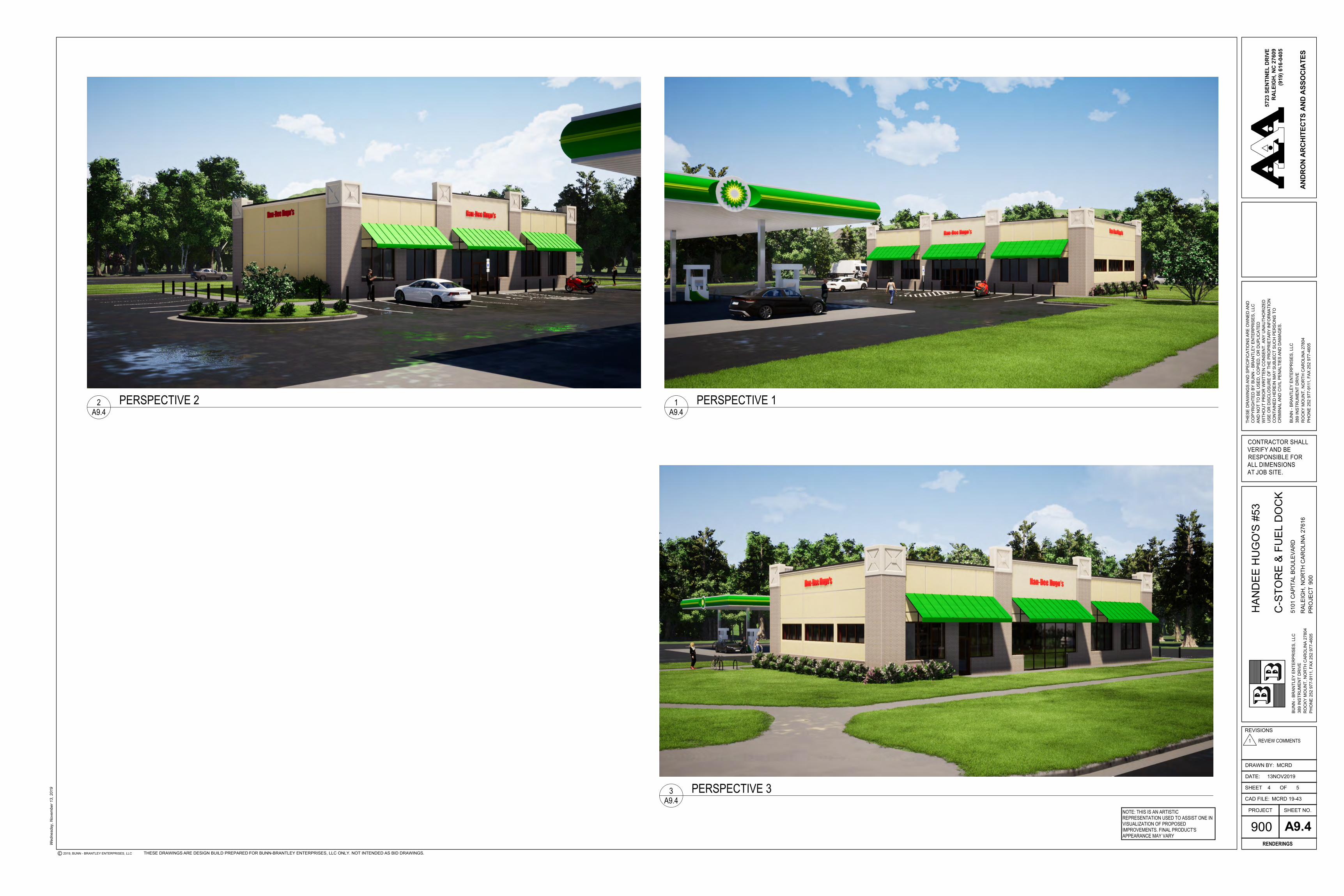
1 PERSPECTIVE 1A9.4
2 PERSPECTIVE 2A9.4
3 PERSPECTIVE 3A9.4
NOTE: THIS IS AN ARTISTICREPRESENTATION USED TO ASSIST ONE INVISUALIZATION OF PROPOSEDIMPROVEMENTS. FINAL PRODUCT'SAPPEARANCE MAY VARY