Embed Size (px)
Citation preview

GEOTECHNICAL ENGINEERING STUDY
FOR
SATELLITE VIEW DRIVE ROUND ROCK, TEXAS


GEOTECHNICAL ENGINEERING STUDY
For
SATELLITE VIEW DRIVE ROUND ROCK, TEXAS
Prepared for
MN CAPITAL STRATEGIES Birmingham, Alabama
Prepared by
RABA KISTNER CONSULTANTS, INC. Austin, Texas
PROJECT NO. AAA16‐016‐00
March 11, 2016

Project No. AAA16‐016‐00 March 11, 2016
TABLE OF CONTENTS
i
INTRODUCTION .......................................................................................................................................... 1
PROJECT DESCRIPTION ............................................................................................................................... 1
LIMITATIONS .............................................................................................................................................. 1
BORINGS AND LABORATORY TESTS ........................................................................................................... 2
SULFATE TESTING .......................................................................................................................................... 3
GENERAL SITE CONDITIONS ....................................................................................................................... 3
SITE DESCRIPTION ......................................................................................................................................... 3
GEOLOGY ....................................................................................................................................................... 3
SEISMIC CONSIDERATIONS ........................................................................................................................... 4
STRATIGRAPHY .............................................................................................................................................. 4
GROUNDWATER ............................................................................................................................................ 5
PAVEMENT RECOMMENDATIONS .............................................................................................................. 5
SWELL/HEAVE POTENTIAL ............................................................................................................................ 5
SUBGRADE STRENGTH CHARACTERIZATION................................................................................................ 5
DESIGN INFORMATION ................................................................................................................................. 6
FLEXIBLE PAVEMENT ..................................................................................................................................... 6
OPTIONS FOR REDUCING EXPANSIVE SOIL‐RELATED MOVEMENTS ........................................................... 6
LONGITUDINAL CRACKING CONSIDERATIONS ............................................................................................. 7 Pavement Enhancement Option Utilizing Geogrid ............................................................................... 8
PAVEMENT CONSTRUCTION CONSIDERATIONS ......................................................................................... 8
SUBGRADE PREPARATION ............................................................................................................................ 8
DRAINAGE CONSIDERATIONS ....................................................................................................................... 8
ON‐SITE CLAY FILL .......................................................................................................................................... 9
LIME TREATMENT OF SUBGRADE ................................................................................................................. 9
FLEXIBLE BASE COURSE ............................................................................................................................... 10
PRIME COAT ................................................................................................................................................ 10
ASPHALTIC CONCRETE SURFACE COURSE .................................................................................................. 11
GEOGRID REINFORCEMENT ........................................................................................................................ 11
MISCELLANEOUS PAVEMENT RELATED CONSIDERATIONS ....................................................................... 11 Utilities .................................................................................................................................................. 11 Curb and Gutter .................................................................................................................................... 12 Pavement Maintenance ....................................................................................................................... 12 Construction Traffic .............................................................................................................................. 12
CONSTRUCTION RELATED SERVICES ......................................................................................................... 12

Project No. AAA16‐016‐00 March 11, 2016
TABLE OF CONTENTS
ii
CONSTRUCTION MATERIALS TESTING AND OBSERVATION SERVICES ...................................................... 12
BUDGETING FOR CONSTRUCTION TESTING ............................................................................................... 13
ATTACHMENTS
The following figures are attached and complete this report: Boring Location Map .......................................................................................................................... Figure 1 Logs of Borings .......................................................................................................................... Figures 2 to 4 Key to Terms and Symbols ................................................................................................................. Figure 5 Results of Soil Analyses ...................................................................................................................... Figure 6 MFPS Output File Important Information About Your Geotechnical Engineering Report
Project No. AAA16‐016‐00 March 11, 2016
1
INTRODUCTION RABA KISTNER Consultants Inc. (RKCI) has completed the authorized subsurface exploration and pavement analysis for the Satellite View Drive extension in Round Rock, Texas. This report briefly describes the procedures utilized during this study and presents our findings along with our recommendations for pavement design and construction guidelines.
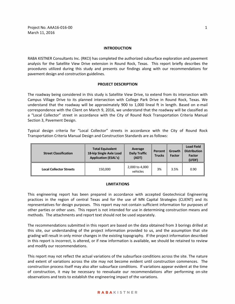
PROJECT DESCRIPTION The roadway being considered in this study is Satellite View Drive, to extend from its intersection with Campus Village Drive to its planned intersection with College Park Drive in Round Rock, Texas. We understand that the roadway will be approximately 900 to 1,000 lineal ft in length. Based on e‐mail correspondence with the Client on March 9, 2016, we understand that the roadway will be classified as a “Local Collector” street in accordance with the City of Round Rock Transportation Criteria Manual Section 3, Pavement Design. Typical design criteria for “Local Collector” streets in accordance with the City of Round Rock Transportation Criteria Manual Design and Construction Standards are as follows:
Street Classification Total Equivalent
18‐kip Single Axle Load Application (ESAL’s)
Average Daily Traffic
(ADT)
Percent Trucks
Growth Factor
Load Field Distribution
Factor (LFDF)
Local Collector Streets 150,000 2,000 to 4,000
vehicles 3% 3.5% 0.90
LIMITATIONS
This engineering report has been prepared in accordance with accepted Geotechnical Engineering practices in the region of central Texas and for the use of MN Capital Strategies (CLIENT) and its representatives for design purposes. This report may not contain sufficient information for purposes of other parties or other uses. This report is not intended for use in determining construction means and methods. The attachments and report text should not be used separately. The recommendations submitted in this report are based on the data obtained from 3 borings drilled at this site, our understanding of the project information provided to us, and the assumption that site grading will result in only minor changes in the existing topography. If the project information described in this report is incorrect, is altered, or if new information is available, we should be retained to review and modify our recommendations. This report may not reflect the actual variations of the subsurface conditions across the site. The nature and extent of variations across the site may not become evident until construction commences. The construction process itself may also alter subsurface conditions. If variations appear evident at the time of construction, it may be necessary to reevaluate our recommendations after performing on‐site observations and tests to establish the engineering impact of the variations.

Project No. AAA16‐016‐00 March 11, 2016
2
The scope of our Geotechnical Engineering Study does not include an environmental assessment of the air, soil, rock, or water conditions either on or adjacent to the site. No environmental opinions are presented in this report. If additional mass site grading is performed at the site which results in elevations that vary significantly from existing grades by more than plus or minus 1 ft, our office should be informed about these changes. If needed and/or if desired, we will reexamine our analyses and make supplemental recommendations.
BORINGS AND LABORATORY TESTS Subsurface conditions at the site were evaluated by 3 borings drilled at the locations shown on the Boring Location Map, Figure 1. Boring locations were documented in the field utilizing a hand‐held GPS device. The borings were drilled to depths of 10 ft below the existing ground surface using a truck‐mounted drilling rig. During drilling operations, the following samples were collected:
Type of Sample Number Collected
Split‐Spoon (with Standard Penetration Test) 2
Undisturbed Shelby Tube 13
Each sample was visually classified in the laboratory by a member of our geotechnical engineering staff. The geotechnical engineering properties of the strata were evaluated by the following tests:
Type of Test Number Conducted
Natural Moisture Content 15
Atterberg Limits 3
Sulfate Testing 1
The results of all laboratory tests are presented in graphical or numerical form on the boring logs illustrated on Figures 2 through 4. A key to classification terms and symbols used on the logs is presented on Figure 5. The results of the laboratory and field testing are also tabulated on Figure 6 for ease of reference. Standard Penetration Test results are noted as “blows per ft” on the boring logs and Figure 6, where “blows per ft” refers to the number of blows by a falling hammer required for 1 ft of penetration into the soil/weak rock (N‐value). Where hard or dense materials were encountered, the tests were terminated at 50 blows even if one foot of penetration had not been achieved. When all 50 blows fall within the first 6 in. (seating blows), refusal “ref” for 6 in. or less will be noted on the boring logs and on Figure 6. Samples will be retained in our laboratory for 30 days after submittal of this report. Other arrangements may be provided at the request of the Client.

Project No. AAA16‐016‐00 March 11, 2016
3
SULFATE TESTING Sulfate testing was performed on a selected sample. The purpose of the sulfate testing was to determine the concentration of soluble sulfates in the subgrade soils, in order to investigate the potential for an adverse reaction to lime in sulfate‐containing soils. The adverse reaction, referred to as sulfate‐induced heave, has been known to cause cohesive subgrade soils to swell in short periods of time, resulting in pavement heaving and possible failure.
Boring Depth Below
Existing Ground Surface (ft)
Type of Soil Sulfate Content
(ppm)
B‐2 2 to 4 Tan Clay 100
*ppm = parts per million
Based on the laboratory test results, the reported values of sulfate content for the tested soils were generally determined to be on the order of 100 ppm. Reported values of sulfate content above 3,000 ppm are known to cause sulfate induced heaving when the soils are mixed with lime. It should be understood that the identification of sulfates based on discrete soil samples cannot totally identify sulfates in all pavement areas. A quality assurance program should be implemented to assist in minimizing the risk of sulfate induced heaving, especially given that the site lies in the Eagle Ford Formation, which is more susceptible to having high concentrations of sulfates.
GENERAL SITE CONDITIONS SITE DESCRIPTION The project site is a tract of agricultural land located between College Park Drive and Campus Village in Round Rock, Texas. The site primarily consists of plowed fields, with a row of trees along Campus Village Drive. The topography slopes downward toward the west with a vertical relief of about 20 ft across the site. GEOLOGY A review of the Geologic Atlas of Texas, Austin Sheet, indicates that this site is naturally underlain with the soils/rock of the Eagle Ford Group. The Eagle Ford Formation generally consists of dark gray calcareous clay. It contains sandy and silty flaggy limestone in the mid‐portion and a bentonite bed at the base. The Eagle Ford Group generally consists of dark gray calcareous clays overlying shale or silty limestone. Key geotechnical engineering considerations for development supported on this formation will be the depth to rock and the expansive nature of the overlying clays.

Project No. AAA16‐016‐00 March 11, 2016
4
SEISMIC CONSIDERATIONS On the basis of the soil borings conducted for this investigation, the upper 100 feet of soil may be characterized as very dense soil and soft rock and a Class C Site Class Definition (Chapter 20 of ASCE 7) has been assigned to this site. On the basis of the United States Geological Survey (USGS) website1 which utilizes the International Building Code (IBC) and U.S. Seismic Design Maps to develop seismic design parameters, the following seismic considerations are associated with this site.
Ss = 0.063g
S1 = 0.035g
Sms = 0.076g
Sm1 = 0.059g
SDS = 0.051g
SD1 = 0.040g Based on the parameters listed above as well as Tables 1613.3.5(1) and 1613.3.5(2) of the 2012 IBC, the Seismic Design Category for both short period and 1 second response accelerations is A. As part of the assumptions required to complete the calculations, a Risk Category of “I or II or III” was selected. STRATIGRAPHY The subsurface conditions encountered at the boring locations are shown on the boring logs, Figures 2 through 4. These boring logs represent our interpretation of the subsurface conditions based on the field logs, visual examination of field samples by our personnel, and test results of selected field samples. Each stratum has been designated by grouping soils that possess similar physical and engineering characteristics. The lines designating the interfaces between strata on the boring logs represent approximate boundaries. Transitions between strata may be gradual. Stratum I consists of dark brown to brown fat clay (CH). These clays are classified as plastic to highly plastic based on measured plasticity indices ranging from 30 to 59. Measured moisture contents range from 25 to 36 percent. Shear strength ranges from 0.4 to 2.3 tsf based on pocket penetrometer test data. Stratum II consists of very stiff to hard, tan fat clay (CH) with calcareous deposits. These clays are classified as highly plastic based on a single measured plasticity index of 49. Measured moisture contents range from 20 to 26 percent. Shear strength ranges from 1.8 to 2.3 tsf based on pocket penetrometer test data. Standard Penetration Test (SPT) N‐values of 22 blows per ft and 50 blows for 11 inches of penetration were measured in this stratum.
1 http://earthquake.usgs.gov/designmaps/us/application.php

Project No. AAA16‐016‐00 March 11, 2016
5
Stratum III consists of hard, gray fat clay (CH) with gypsum. A single measured moisture content of 19 percent was determined in this stratum. Shear strength was determined to be 2.3 tsf based on a pocket penetrometer test. This stratum was only encountered in Boring B‐1. GROUNDWATER Groundwater was not observed in the borings either during or immediately upon completion of the drilling operations. All borings remained dry during the field exploration phase. However, it is possible for groundwater to exist beneath this site at shallow depths on a transient basis, particularly following periods of precipitation. Fluctuations in groundwater levels occur due to variation in rainfall and surface water run‐off. The construction process itself may also cause variations in the groundwater level.
PAVEMENT RECOMMENDATIONS We understand that Satellite View Drive will be classified as a “Local Collector” street in accordance with the City of Round Rock Transportation Criteria Manual Section 3, Pavement Design. SWELL/HEAVE POTENTIAL
The anticipated ground movements due to swelling of the underlying soils at the site were estimated using the empirical procedure, Texas Department of Transportation (TxDOT) Tex‐124‐E, Method for Determining the Potential Vertical Rise (PVR). PVR values ranging from 4‐3/4 to 5‐1/4 in. were estimated for the stratigraphic conditions encountered in our borings. A surcharge load of 1 psi (concrete slab and sand layer), an active zone of 15 ft, and dry moisture conditions were assumed in estimating the above PVR values.
The TxDOT method of estimating expansive soil‐related movements is based on empirical correlations utilizing the measured plasticity indices and assuming typical seasonal fluctuations in moisture content. If desired, other methods of estimating expansive soil‐related movements are available, such as estimations based on swell tests and/or soil‐suction analyses. However, the performance of these tests and the detailed analysis of expansive soil‐related movements were beyond the scope of the current study. It should also be noted that actual movements can exceed the calculated PVR values due to isolated changes in moisture content or if water seeps into the soils to greater depths than the assumed active zone depth due to deep trenching or excavations. SUBGRADE STRENGTH CHARACTERIZATION
For the purpose of this report, RKCI has assigned the following subgrade stiffness coefficients. These values are based on our experience in conducting laboratory testing in similar soils and correlation with the engineering properties determined during laboratory testing.
Material
Subgrade Stiffness
Coefficient
Dark Brown or Brown Clay 0.165

Project No. AAA16‐016‐00 March 11, 2016
6
DESIGN INFORMATION To determine the required pavement sections for the proposed “Local Collector” streets, RKCI utilized City of Austin’s computerized program Municipal Flexible Pavement Design (MFPS‐1), Version 1.0. The following design parameters were utilized for the design of flexible pavements for the proposed type of street:
Street Classification Design Life Average Daily Trips
(ADT) Reliability
Serviceability Initial/Terminal
Local Collector Streets 20 years 4,000 90 4.2/1.5
Additional design parameters utilized to determine minimum layer thicknesses for flexible pavements as well as MFPS output files have been provided as attachments to this report. FLEXIBLE PAVEMENT Flexible pavement sections recommended for this site are as listed in the table below:
Layer Description Layer Thickness
Local Collector Streets
Type “D” Surface Course, Item 340 Flexible Base, Item 210 Lime Treated Subgrade, Item 202 Combined Total
2.0 in. 14.0 in. 10.0 in. 26.0 in.
*This pavement section meets the minimum required pavement sections required in the City of Round Rock Transportation Criteria Manual Section 3, Pavement Design.
The pavement section derived is structurally adequate for the given traffic levels and existing clay subgrade strength, but does not consider the long‐term effects of pavement roughness and/or longitudinal cracking due to heave, which can only be addressed by the measures discussed in the following sections. If mitigation of expansive soils is not implemented to desirable limits by removal and replacement, the stakeholders of the project should consider the installation of a geogrid layer in addition to the pavement sections above. Please refer to the Pavement Enhancement Option Utilizing Geogrid section of this report. OPTIONS FOR REDUCING EXPANSIVE SOIL‐RELATED MOVEMENTS Subgrade soils that are highly expansive (i.e., highly plastic soils) will heave when water is introduced, causing the pavement to become rough or uneven over time. Pavement roughness is generally defined as an expression of irregularities in the pavement surface that adversely affect the ride quality of a vehicle (and thus the user). Roughness is an important pavement characteristic because it affects not only ride quality but also vehicle costs, fuel consumption, and maintenance costs. Pavement heave can be reduced

Project No. AAA16‐016‐00 March 11, 2016
7
through various measures but cannot be totally eliminated without full removal of the problematic soil. Measures available for reducing heave include:
Soil Stabilization with Lime or Other Pozzolans
Removal and Replacement of High PI Soils
Drains or Barriers to Collect or Inhibit Moisture Infiltration Soil stabilization with lime is typically used to reduce the swelling potential of the upper portion of the pavement subgrade containing moderately plastic soils. Lime and water are mixed with the top 6 to 12 inches (or possibly more) of the subgrade and allowed to mellow or cure for a period of time. After mellowing the soil‐lime mixture is compacted to form a strong soil matrix that can improve pavement performance and potentially reduce soil heave. However, in highly plastic soils, lime stabilization of only the top portion of the expansive subgrade may not provide an acceptable reduction in PVR. For a more substantial reduction in PVR, removal and replacement of the high PI soil may be the only method available to reduce the potential vertical rise of the pavement to an acceptable level. As stated previously though, it must be recognized that partial removal of expansive clay soil only reduces the potential (or risk) of the damage swell can cause to a pavement and does not completely eliminate this risk. In addition, capturing water infiltration via French drains, pavement edge drains, or inhibiting water through the use of vertical moisture barriers would reduce the potential for heave since one important component of the heaving mechanism, water, would be reduced. LONGITUDINAL CRACKING CONSIDERATIONS Asphalt pavement sections in highly expansive soil environments, such as those encountered at this site, can develop longitudinal cracking along unprotected pavement edges. In the semi‐arid climate of south central Texas this condition typically occurs along the unprotected edges of pavements where the adjoining grounds are not developed, i.e. not landscaped/irrigated or otherwise maintained. The longitudinal cracking generally occurs between 2 to 4 feet inside of and parallel to the unprotected edges of the pavement. Differential drying and shrinkage of the highly expansive clay subgrade between the exposed pavement edge and that beneath the pavement section commonly causes the cracking. This problem can best be addressed by providing either a horizontal or vertical moisture barrier at the unprotected pavement edge. A horizontal barrier is commonly in the form of a paved shoulder extending 8 feet or greater beyond the edge of the pavement. Other methods of shoulder treatment, such as using geofabric or synthetic sheet liner beyond the edge of the roadway, are sometimes used in an effort to help reduce longitudinal cracking. Although this alternative does not eliminate the longitudinal cracking phenomenon, the location of the cracking is transferred to the shoulder rather than within the traffic lane. Vertical barriers installed along the unprotected edges of roadway pavements are also effective in preventing non‐uniform drying and shrinkage of the subgrade clays. These barriers are typically in the form of a vertical moisture barrier/membrane extending a minimum of 6 feet below the top of the subgrade at the pavement edge. Both types of barriers must be sealed at the edge of the pavement to prevent a crack that would facilitate the drying of the subgrade clays.
Project No. AAA16‐016‐00 March 11, 2016
8
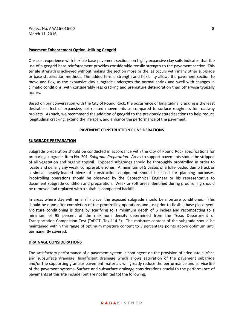
Pavement Enhancement Option Utilizing Geogrid Our past experience with flexible base pavement sections on highly expansive clay soils indicates that the use of a geogrid base reinforcement provides considerable tensile strength to the pavement section. This tensile strength is achieved without making the section more brittle, as occurs with many other subgrade or base stabilization methods. The added tensile strength and flexibility allows the pavement section to move and flex, as the expansive clay subgrade undergoes the normal shrink and swell with changes in climatic conditions, with considerably less cracking and premature deterioration than otherwise typically occurs. Based on our conversation with the City of Round Rock, the occurrence of longitudinal cracking is the least desirable effect of expansive, soil‐related movements as compared to surface roughness for roadway projects. As such, we recommend the addition of geogrid to the previously stated sections to help reduce longitudinal cracking, extend the life span, and enhance the performance of the pavement.
PAVEMENT CONSTRUCTION CONSIDERATIONS SUBGRADE PREPARATION Subgrade preparation should be conducted in accordance with the City of Round Rock specifications for preparing subgrade, Item No. 201, Subgrade Preparation. Areas to support pavements should be stripped of all vegetation and organic topsoil. Exposed subgrades should be thoroughly proofrolled in order to locate and densify any weak, compressible zones. A minimum of 5 passes of a fully‐loaded dump truck or a similar heavily‐loaded piece of construction equipment should be used for planning purposes. Proofrolling operations should be observed by the Geotechnical Engineer or his representative to document subgrade condition and preparation. Weak or soft areas identified during proofrolling should be removed and replaced with a suitable, compacted backfill. In areas where clay will remain in place, the exposed subgrade should be moisture conditioned. This should be done after completion of the proofrolling operations and just prior to flexible base placement. Moisture conditioning is done by scarifying to a minimum depth of 6 inches and recompacting to a minimum of 95 percent of the maximum density determined from the Texas Department of Transportation Compaction Test (TxDOT, Tex‐114‐E). The moisture content of the subgrade should be maintained within the range of optimum moisture content to 3 percentage points above optimum until permanently covered. DRAINAGE CONSIDERATIONS The satisfactory performance of a pavement system is contingent on the provision of adequate surface and subsurface drainage. Insufficient drainage which allows saturation of the pavement subgrade and/or the supporting granular pavement materials will greatly reduce the performance and service life of the pavement systems. Surface and subsurface drainage considerations crucial to the performance of pavements at this site include (but are not limited to) the following:

Project No. AAA16‐016‐00 March 11, 2016
9
1) Any known natural or man‐made subsurface seepage at the site which may occur at sufficiently shallow depths as to influence moisture contents within the subgrade should be intercepted by drainage ditches or below grade French drains.
2) Final site grading should eliminate isolated depressions adjacent to curbs which may allow surface water to pond and infiltrate into the underlying soils. Curbs should completely penetrate base materials and should be installed to sufficient depth to reduce infiltration of water beneath the curbs.
3) Pavement surfaces should be maintained to help minimize surface ponding and to provide rapid sealing of any developing cracks. These measures will help reduce infiltration of surface water downward through the pavement section.
ON‐SITE CLAY FILL As previously discussed, the pavement recommendations presented in this report were prepared assuming on‐site clays will be used for fill grading in proposed pavement areas. If used, we recommend that on‐site soils be placed in loose lifts not exceeding 8 inches in thickness and compacted to at least 95 percent of the maximum density as determined by TxDOT, Tex‐114‐E. The moisture content of the fill should be maintained within the range of optimum water content to 3 percentage points above the optimum water content until permanently covered. We recommend that fill materials be free of roots and other organic or degradable material. We also recommend that the maximum particle size not exceed 4 inches or one half the lift thicknesses, whichever is smaller. If other import fill materials are utilized, RKCI should be notified, as additional CBR testing and thicker pavement sections may be required. It is imperative that the subgrade stiffness coefficient utilized in the pavement design process be met or exceeded by the fill material. In the event that the clay fill used is different than the existing subgrade, the recommendations in this report could be invalidated and the design engineer must be consulted to determine if additional CBR testing and thicker pavement sections are required. LIME TREATMENT OF SUBGRADE Lime treatment of the subgrade soils should be in accordance with the City of Round Rock Standard Specifications, Item 202, Hydrated Lime and Lime Slurry. A sufficient quantity of hydrated lime should be mixed with the subgrade soils to reduce the soil‐lime mixture plasticity index to 15 or less. For estimating purposes, we recommend that 8 percent lime by weight be assumed for treatment. For construction purposes, we recommend that the optimum lime content of the subgrade soils be determined by laboratory testing. Lime‐treated subgrade soils should be compacted to a minimum of 95 percent of the maximum density at moisture content within the range of optimum moisture content to 3 percentage points above the optimum moisture content as determined by Tex‐121‐E. Lime treatment should extend at least 3 ft beyond the curb as required by the City of Round Rock. It is also recommended to perform additional laboratory testing to determine the concentration of soluble sulfates in the subgrade soils, in order to investigate the potential for a recently reported adverse reaction to lime in certain sulfate‐containing soils. The adverse reaction, referred to as sulfate‐induced heave, has been known to cause cohesive subgrade soils to swell in short periods of time, resulting in pavement heaving and possible failure.

Project No. AAA16‐016‐00 March 11, 2016
10
FLEXIBLE BASE COURSE The flexible base course should be crushed limestone conforming to City of Round Rock Standard Specifications, Item 210, Flexible Base. The material should be from a source approved by the City and meet the following gradation.
Sieve Designation
% Retained
1‐3/4” 0
7/8” 10‐35
3/8” 30‐50
#4 45‐65
#40 70‐85
Other Requirements
Maximum Plasticity Index 10
Maximum Wet Ball Mill 42
Maximum increase in passing #40 sieve from wet ball mill test
20
The minimum compressive strength of the material under triaxial loading should be 35 psi with 0 psi lateral pressure and 175 psi with 15 psi lateral pressure. Base course should be placed in lifts with a maximum thickness of 6 inches and compacted to a minimum of 100 percent of the maximum density as determined by Tex‐113‐E, with a moisture content within plus or minus 2 percent of the optimum moisture content. As required by the City of Round Rock, it is understood that the flexible base materials and stabilized subgrade are specified to be extended 36 inches beyond the back side of the curbs where stabilization is required. It is recommended to implement the placement of an impermeable clay cap overlying the flexible base overbuild, removal of the flexible base material behind the curb and place an impermeable clay, or have the concrete curb completely penetrate the flexible base materials. These alternatives are necessary as we anticipate the presence of irrigation and surface water runoff existing behind the curb over the service life of the roadway. It is possible that water could infiltrate the flexible base beneath the concrete curb and cause the flexible base to saturate and weaken and the underlying clay to expand. This is especially true on sites sloping downward towards the roadway. PRIME COAT The prime coat should conform to the City of Round Rock Standard Specifications, Item 306, Prime Coat.

Project No. AAA16‐016‐00 March 11, 2016
11
ASPHALTIC CONCRETE SURFACE COURSE The asphaltic concrete surface course should conform to City of Round Rock Standard Specifications, Item 340, Type C or D, Hot Mix Asphalt Concrete Pavement. The asphaltic concrete should be compacted to a range between 91 and 96 percent of the maximum theoretical specific gravity (Rice) of the mixture determined according to Test Method Tex‐227‐F. Pavement specimens, which shall be either cores or sections of asphaltic pavement, will be tested according to Test Method Tex‐207‐F. The nuclear‐density gauge or other methods which correlate satisfactorily with results obtained from project roadway specimens may be used when approved by the Engineer. Unless otherwise shown on the plans, the Contractor shall be responsible for obtaining the required roadway specimens at their expense and in a manner and at locations selected by the Engineer. GEOGRID REINFORCEMENT The geogrid reinforcement should meet Type II geogrid that meets the Texas Department of Transportation Department Materials Specification DMS ‐ 6240, Geogrid for Base/Embankment Reinforcement. The geogrid should be placed at the bottom of the flexible (granular) base section in all cases. An alternative to the above geogrid should not be considered without approval from RKCI.
MISCELLANEOUS PAVEMENT RELATED CONSIDERATIONS
Utilities
Utilities which project through slab‐on‐grade, slab‐on‐fill, or any other rigid unit should be designed with either some degree of flexibility or with sleeves. Such design features will help reduce the risk of damage to the utility lines as vertical movements occur.
Our experience indicates that significant settlement of backfill can occur in utility trenches, particularly when trenches are deep, when backfill materials are placed in thick lifts with insufficient compaction, and when water can access and infiltrate the trench backfill materials. The potential for water to access the backfill is increased where water can infiltrate flexible base materials due to insufficient penetration of curbs, and at sites where geological features can influence water migration into utility trenches (such as fractures within a rock mass or at contacts between rock and clay formations). It is our belief that another factor which can significantly impact settlement is the migration of fines within the backfill into the open voids in the underlying free‐draining bedding material.
To reduce the potential for settlement in utility trenches, we recommend that consideration be given to the following:
All backfill materials should be placed and compacted in controlled lifts appropriate for the type of backfill and the type of compaction equipment being utilized and all backfilling procedures should be tested and documented. Trench backfill materials should be placed in loose lifts not exceeding 8 inches in thickness and compacted to at least 95 percent of maximum density as determined by TxDOT, Tex‐113‐E, Compaction Test. The moisture content of the fill should be maintained within the range of 2 percentage points below to 2 percentage points above the optimum moisture content for non‐cohesive soils and

Project No. AAA16‐016‐00 March 11, 2016
12
maintained within the range of optimum to 3 percentage points above optimum moisture content for cohesive soils until final compaction.
Curbs should completely penetrate base materials and be installed to a sufficient depth to reduce water infiltration beneath the curbs into the pavement base materials.
Consideration should be given to wrapping free‐draining bedding gravels with a geotextile fabric (similar to Mirafi 140N) to reduce the infiltration and loss of fines from backfill material into the interstitial voids in bedding materials.
Curb and Gutter
It is good practice to construct curbs such that the depth of the curb extends through the entire depth of the granular base material to act as a protective barrier against the infiltration of water into the granular base. Pavements that do not have this protective barrier to moisture tend to develop longitudinal cracks 1 to 2 ft from the edge of the pavement. Once these cracks develop, further degradation and weakening of the underlying granular base may occur due to water seepage through the cracks. Pavement Maintenance Regular pavement maintenance is critical in maintaining pavement performance over a period of several years. All cracks that develop in asphalt pavements should be regularly sealed. Areas of moderate to severe fatigue cracking (also known as alligator cracking) should be sawcut and removed. The underlying base should be checked for contamination or loss of support and any insufficiencies fixed or removed and the entire area patched. Other typical TxDOT or Williamson County maintenance techniques should be followed as required. Construction Traffic Construction traffic on prepared subgrade, granular base or asphalt treated base (black base) should be restricted as much as possible until the protective asphalt surface pavement is applied. Significant damage to the underlying layers resulting in weakening may occur if heavily loaded vehicles are allowed to use these areas.
CONSTRUCTION RELATED SERVICES CONSTRUCTION MATERIALS TESTING AND OBSERVATION SERVICES As presented in the attachment to this report, Important Information About Your Geotechnical Engineering Report, subsurface conditions can vary across a project site. The conditions described in this report are based on interpolations derived from a limited number of data points. Variations will be encountered during construction, and only the geotechnical design engineer will be able to determine if these conditions are different than those assumed for design. Construction problems resulting from variations or anomalies in subsurface conditions are among the most prevalent on construction projects and often lead to delays, changes, cost overruns, and disputes. These variations and anomalies can best be addressed if the geotechnical engineer of record, RKCI is

Project No. AAA16‐016‐00 March 11, 2016
13
retained to perform construction observation and testing services during the construction of the project. This is because:
RKCI has an intimate understanding of the geotechnical engineering report’s findings and recommendations. RKCI understands how the report should be interpreted and can provide such interpretations on site, on the client’s behalf.
RKCI knows what subsurface conditions are anticipated at the site.
RKCI is familiar with the goals of the owner and project design professionals, having worked with them in the development of the geotechnical workscope. This enables RKCI to suggest remedial measures (when needed) which help meet the owner’s and the design teams’ requirements.
RKCI has a vested interest in client satisfaction, and thus assigns qualified personnel whose principal concern is client satisfaction. This concern is exhibited by the manner in which contractors’ work is tested, evaluated and reported, and in selection of alternative approaches when such may become necessary.
RKCI cannot be held accountable for problems which result due to misinterpretation of our findings or recommendations when we are not on hand to provide the interpretation which is required.
BUDGETING FOR CONSTRUCTION TESTING Appropriate budgets need to be developed for the required construction testing and observation activities. At the appropriate time before construction, we advise that RKCI and the project designers meet and jointly develop the testing budgets, as well as review the testing specifications as it pertains to this project. Once the construction testing budget and scope of work are finalized, we encourage a preconstruction meeting with the selected contractor to review the scope of work to make sure it is consistent with the construction means and methods proposed by the contractor. RKCI looks forward to the opportunity to provide continued support on this project, and would welcome the opportunity to meet with the Project Team to develop both a scope and budget for these services.
* * * * * * * * * * * * * * * * * *

ATTACHMENTS

!?
!? !?
University Boulevard
College Park Drive
Campus Village Drive
Satellite View Drive
B-3B-2
B-1
BORING LOCATION MAPSATELLITE VIEW DRIVEROUND ROCK, TEXAS
PROJECT No.:AAA16-016-00DRAWN BY:ISSUE DATE:
REVIEWED BY:CHECKED BY:
KRB03/10/2016
YGTRTS
NOTE: This Drawing is Provided for Illustration Only, May Not be to Scale and is Not Suitable for Design or Construction Purposes
µ
Austin
GeorgetownGeorgetown
§̈¦35
§̈¦35§̈¦35
£¤79
Williamson
TravisSITE LOCATION MAP
S I T E
FIGURE1WILLIAMSON
COUNTY
_̂
TBPE Firm Number 3257
8100 Cameron Road, Suite B-150Austin, Texas 78754(512)339-1745 TEL(512)339-6174 FAX
www.rkci.com
LEGEND!? BORING
PROPOSED RIGHT OF WAY0 100 20050
FEET1 INCH = 200 FEET

CLAY (CH), Fat, Firm to Hard, Dark Brown
CLAY (CH), Fat, Hard, Tan
CLAY, Fat, Hard, Gray, with gypsum
Boring Terminated
59
NOTES:1. Groundwater not encountered during
drilling operations.2. Borehole was backfilled with auger
cuttings.
LOG OF BORING NO. B-1
PLA
STIC
ITY
IND
EX
Straight Flight Auger
% -2
00
DRILLINGMETHOD: LOCATION:
PLASTICLIMIT
LIQUIDLIMIT
WATERCONTENT
BLO
WS
PER
FT
10 20 30 40 50 60 70 80
DESCRIPTION OF MATERIAL0.5 1.0 1.5 2.0 2.5 3.0 3.5 4.0
SHEAR STRENGTH, TONS/FT2
UN
IT D
RYW
EIG
HT,
pcf
N 30.56651; W 97.66132
NO
TE: T
HES
E LO
GS
SHO
ULD
NO
T BE
USE
D S
EPAR
ATEL
Y FR
OM
TH
E PR
OJE
CT R
EPO
RT
DEPTH DRILLED:DATE DRILLED:
DEPTH TO WATER:DATE MEASURED:
5
10
15
20
25
30
35
SYM
BOL
SAM
PLES
Satellite View DriveRound Rock, Texas
Dry2/18/2016
DEP
TH, F
T
10.0 ft2/18/2016
AAA16-016-002
PROJ. No.:FIGURE:
TBPE Firm Registration No. F-3257

CLAY (CH), Fat, Very Stiff, Dark Brown toBrown
CLAY (CH), Fat, Hard, Tan, with calcareousdeposits
Boring Terminated
49
NOTES:1. Groundwater not encountered during
drilling operations.2. Borehole was backfilled with auger
cuttings.
LOG OF BORING NO. B-2
PLA
STIC
ITY
IND
EX
Straight Flight Auger
% -2
00
DRILLINGMETHOD: LOCATION:
PLASTICLIMIT
LIQUIDLIMIT
WATERCONTENT
BLO
WS
PER
FT
10 20 30 40 50 60 70 80
DESCRIPTION OF MATERIAL0.5 1.0 1.5 2.0 2.5 3.0 3.5 4.0
SHEAR STRENGTH, TONS/FT2
UN
IT D
RYW
EIG
HT,
pcf
N 30.56675; W 97.66028
NO
TE: T
HES
E LO
GS
SHO
ULD
NO
T BE
USE
D S
EPAR
ATEL
Y FR
OM
TH
E PR
OJE
CT R
EPO
RT
DEPTH DRILLED:DATE DRILLED:
DEPTH TO WATER:DATE MEASURED:
5
10
15
20
25
30
35
SYM
BOL
SAM
PLES
Satellite View DriveRound Rock, Texas
Dry2/18/2016
DEP
TH, F
T
10.0 ft2/18/2016
AAA16-016-003
PROJ. No.:FIGURE:
TBPE Firm Registration No. F-3257

CLAY (CH), Fat, Hard, Dark Brown toBrown
CLAY (CH), Fat, Very Stiff to Hard, Tan
Boring Terminated
30
NOTES:1. Groundwater not encountered during
drilling operations.2. Borehole was backfilled with auger
cuttings.
LOG OF BORING NO. B-3
PLA
STIC
ITY
IND
EX
Straight Flight Auger
% -2
00
DRILLINGMETHOD: LOCATION:
PLASTICLIMIT
LIQUIDLIMIT
WATERCONTENT
BLO
WS
PER
FT
10 20 30 40 50 60 70 80
DESCRIPTION OF MATERIAL0.5 1.0 1.5 2.0 2.5 3.0 3.5 4.0
SHEAR STRENGTH, TONS/FT2
UN
IT D
RYW
EIG
HT,
pcf
N 30.56678; W 97.65928
NO
TE: T
HES
E LO
GS
SHO
ULD
NO
T BE
USE
D S
EPAR
ATEL
Y FR
OM
TH
E PR
OJE
CT R
EPO
RT
DEPTH DRILLED:DATE DRILLED:
DEPTH TO WATER:DATE MEASURED:
5
10
15
20
25
30
35
SYM
BOL
SAM
PLES
Satellite View DriveRound Rock, Texas
Dry2/18/2016
DEP
TH, F
T
10.0 ft2/18/2016
AAA16-016-004
PROJ. No.:FIGURE:
TBPE Firm Registration No. F-3257
55
22

PROJECT NO. AAA16-016-00
CLAY-SHALE
SAMPLE TYPES
NO INFORMATION
BLANK PIPE
ASPHALT
IGNEOUS
LIMESTONE
FILL
GEOPROBESAMPLER
TEXAS CONEPENETROMETER
DISTURBED
METAMORPHIC
MARL
MUDROTARY
NORECOVERY SPLIT BARREL
SPLIT SPOONNX CORE
SHELBY TUBE
CALCAREOUS
CLAY
CLAYEY
GRAVEL
GRAVELLY
WELL CONSTRUCTION AND PLUGGING MATERIALS
SILTSTONE
CALICHE
CONGLOMERATE
AIRROTARY
GRABSAMPLE
DOLOMITE
BENTONITE
CORE
SOIL TERMS OTHER
NOTE: VALUES SYMBOLIZED ON BORING LOGS REPRESENT SHEARSTRENGTHS UNLESS OTHERWISE NOTED
BASE
KEY TO TERMS AND SYMBOLS
CUTTINGS
SAND
SANDY
SILT
SILTY
CHALK
STRENGTH TEST TYPES
CEMENT GROUT GRAVEL
SAND
POCKET PENETROMETER
TORVANE
UNCONFINED COMPRESSION
TRIAXIAL COMPRESSIONUNCONSOLIDATED-UNDRAINED
TRIAXIAL COMPRESSIONCONSOLIDATED-UNDRAINED
BRICKS /PAVERS
SCREEN
MATERIAL TYPES
VOLCLAY
SANDSTONE
SHALE
ROCK TERMS
WASTE
CONCRETE/CEMENT
PEAT
BENTONITE &CUTTINGS
CONCRETE/CEMENT
CLAYSTONE
ROTOSONIC-DAMAGED
ROTOSONIC-INTACT
PITCHER
FIGURE 5aREVISED 04/2012

PROJECT NO. AAA16-016-00
KEY TO TERMS AND SYMBOLS (CONT'D)
TERMINOLOGY
RELATIVE DENSITY PLASTICITYCOHESIVE STRENGTH
PenetrationResistance
Blows per ftDegree ofPlasticity
PlasticityIndex
RelativeDensity
ResistanceBlows per ft
0
4
10
30
-
-
-
-
>
4
10
30
50
50
Very Loose
Loose
Medium Dense
Dense
Very Dense
ConsistencyCohesion
TSF
-
-
-
-
>
-
-
-
-
-
>
Benzene
Toluene
Ethylbenzene
Total Xylenes
Total BTEX
Total Petroleum Hydrocarbons
Not Detected
Not Analyzed
Not Recorded/No Recovery
Organic Vapor Analyzer
Parts Per Million
2
4
8
15
30
30
Very Soft
Soft
Firm
Stiff
Very Stiff
Hard
0
2
4
8
15
0
0.125
0.25
0.5
1.0
-
-
-
-
-
>
0.125
0.25
0.5
1.0
2.0
2.0
0
5
10
20
5
10
20
40
40
None
Low
Moderate
Plastic
Highly Plastic
=
=
=
=
=
=
=
=
=
=
=
ABBREVIATIONS
Qam, Qas, Qal
Qat
Qbc
Qt
Qao
Qle
Q-Tu
Ewi
Emi
Mc
EI
Kknm
Kpg
Kau
=
=
=
=
=
=
=
=
=
=
=
=
=
=
Kef
Kbu
Kdr
Kft
Kgt
Kep
Kek
Kes
Kew
Kgr
Kgru
Kgrl
Kh
Quaternary Alluvium
Low Terrace Deposits
Beaumont Formation
Fluviatile Terrace Deposits
Seymour Formation
Leona Formation
Uvalde Gravel
Wilcox Formation
Midway Group
Catahoula Formation
Laredo Formation
Navarro Group and MarlbrookMarl
Pecan Gap Chalk
Austin Chalk
=
=
=
=
=
=
=
=
=
=
=
=
=
Eagle Ford Shale
Buda Limestone
Del Rio Clay
Fort Terrett Member
Georgetown Formation
Person Formation
Kainer Formation
Escondido Formation
Walnut Formation
Glen Rose Formation
Upper Glen Rose Formation
Lower Glen Rose Formation
Hensell Sand
B
T
E
X
BTEX
TPH
ND
NA
NR
OVA
ppm
Terms used in this report to describe soils with regard to their consistency or conditions are in general accordance with thediscussion presented in Article 45 of SOILS MECHANICS IN ENGINEERING PRACTICE, Terzaghi and Peck, John Wiley & Sons, Inc.,1967, using the most reliable information available from the field and laboratory investigations. Terms used for describing soilsaccording to their texture or grain size distribution are in accordance with the UNIFIED SOIL CLASSIFICATION SYSTEM, as describedin American Society for Testing and Materials D2487-06 and D2488-00, Volume 04.08, Soil and Rock; Dimension Stone;Geosynthetics; 2005.
The depths shown on the boring logs are not exact, and have been estimated to the nearest half-foot. Depth measurements maybe presented in a manner that implies greater precision in depth measurement, i.e 6.71 meters. The reader should understandand interpret this information only within the stated half-foot tolerance on depth measurements.
FIGURE 5bREVISED 04/2012

PROJECT NO. AAA16-016-00
KEY TO TERMS AND SYMBOLS (CONT'D)
TERMINOLOGY
SOIL STRUCTURE
SAMPLING METHODS
Having planes of weakness that appear slick and glossy.Containing shrinkage or relief cracks, often filled with fine sand or silt; usually more or less vertical.Inclusion of material of different texture that is smaller than the diameter of the sample.Inclusion less than 1/8 inch thick extending through the sample.Inclusion 1/8 inch to 3 inches thick extending through the sample.Inclusion greater than 3 inches thick extending through the sample.Soil sample composed of alternating partings or seams of different soil type.Soil sample composed of alternating layers of different soil type.Soil sample composed of pockets of different soil type and layered or laminated structure is not evident.Having appreciable quantities of carbonate.Having more than 50% carbonate content.
SlickensidedFissuredPocketPartingSeamLayerLaminatedInterlayeredIntermixedCalcareousCarbonate
RELATIVELY UNDISTURBED SAMPLING
NOTE: To avoid damage to sampling tools, driving is limited to 50 blows during or after seating interval.
STANDARD PENETRATION TEST (SPT)
Cohesive soil samples are to be collected using three-inch thin-walled tubes in general accordance with the Standard Practicefor Thin-Walled Tube Sampling of Soils (ASTM D1587) and granular soil samples are to be collected using two-inch split-barrelsamplers in general accordance with the Standard Method for Penetration Test and Split-Barrel Sampling of Soils (ASTMD1586). Cohesive soil samples may be extruded on-site when appropriate handling and storage techniques maintain sampleintegrity and moisture content.
Description
25 blows drove sampler 12 inches, after initial 6 inches of seating.50 blows drove sampler 7 inches, after initial 6 inches of seating.50 blows drove sampler 3 inches during initial 6-inch seating interval.
Blows Per Foot
2550/7"Ref/3"
FIGURE 5c
A 2-in.-OD, 1-3/8-in.-ID split spoon sampler is driven 1.5 ft into undisturbed soil with a 140-pound hammer free falling 30 in.After the sampler is seated 6 in. into undisturbed soil, the number of blows required to drive the sampler the last 12 in. is theStandard Penetration Resistance or "N" value, which is recorded as blows per foot as described below.
REVISED 04/2012
SPLIT-BARREL SAMPLER DRIVING RECORD

B-1 0.0 to 2.0 30 82 23 59 CH 1.00 PP
2.0 to 4.0 36 0.35 PP
4.0 to 6.0 25 2.10 PP
6.0 to 8.0 20 2.25 PP
8.0 to 10.0 19 2.25 PP
B-2 0.0 to 2.0 28 1.50 PP
2.0 to 4.0 25 70 21 49 CH 2.25 PP
4.0 to 6.0 25 2.25 PP
6.0 to 8.0 26 2.25 PP
8.0 to 10.0 26 2.25 PP
B-3 0.0 to 2.0 28 47 17 30 CL 2.25 PP
2.0 to 4.0 23 1.75 PP
4.0 to 6.0 25 2.25 PP
6.0 to 8.0 55 21
8.0 to 10.0 22 22
PlasticityIndex
LiquidLimit
PP = Pocket Penetrometer TV = Torvane UC = Unconfined Compression FV = Field Vane
PlasticLimit
WaterContent
(%)
Dry UnitWeight
(pcf)
PROJECT NAME:
FILE NAME: AAA16-016-00.GPJ
USCS % -200Sieve
ShearStrength
(tsf)
StrengthTest
BoringNo.
3/11/2016
UU = Unconsolidated Undrained Triaxial
SampleDepth
(ft)
CU = Consolidated Undrained Triaxial
Satellite View DriveRound Rock, Texas
RESULTS OF SOIL SAMPLE ANALYSES
Blowsper ft
FIGURE 6
PROJECT NO. AAA16-016-00

sview.TXT� MFPS-1 MUNICIPAL FLEXIBLE PAVEMENT DESIGN SYSTEM, VERSION 1.0, 8/83 ADAPTED FROM TEXAS SDHPT FPS-11 PROGRAM FOR CITY OF AUSTIN RABA-KISTNER-BRYTEST CONSULTANTS, AUSTIN, TEXAS
PROBLEM TITLE (DESCRIPTION) SATELLITE VIEW DRIVE (LOCAL COLLECTOR)
***** PAVEMENT *****
TOTAL NUMBER OF LANES IN FACILITY . . . . . . . . 2 TOTAL NUMBER OF CURBS IN FACILITY . . . . . . . . 2 NUMBER OF LAYERS CONSIDERED IN THIS PROBLEM . . . 3 LANE WIDTH (FEET) . . . . . . . . . . . . . . . . 18.50 CURB HEIGHT (INCHES). . . . . . . . . . . . . . . 6.00 CONCRETE CURB CONSTRUCTION COST ($/LF). . . . . . 4.50 THICKENED EDGE FIXED COST ($/LF). . . . . . . . . .00 THICKENED EDGE INCREMENTAL COST ($/IN/LF) . . . . .00
***** LAYER *****
MIN. MAX. THICK. SALV. LAYER LAYER LAYER DEPTH DEPTH INCR. COST COST VALUE STIFF. NO. CODE DESCRIPTION (IN.) (IN.) (IN.) ($/CY) ($/SY) (%) COEF. ----- ----- --------------- ----- ----- ------ ------ ------ ----- ------ 1 A HMAC 2.00 2.50 .50 123.00 .00 30.0 .960 2 B BASE 12.00 16.00 1.00 15.00 .00 20.0 .500 3 C LIME 10.00 14.00 1.00 30.00 .00 20.0 .320
***** SUBGRADE *****
SWELLING PROBABILITY. . . . . . . . . . . . . . . 1.00 SWELLING RATE CONSTANT. . . . . . . . . . . . . . .11 POTENTIAL VERTICAL RISE (INCHES). . . . . . . . . 5.30 SUBGRADE EXCAVATION COST ($/CY) . . . . . . . . . 4.50 SUBGRADE COST ($/SY). . . . . . . . . . . . . . . .00 SUBGRADE STIFFNESS COEFFICIENT. . . . . . . . . . .165
***** AC OVERLAY *****
MINIMUM AC OVERLAY THICKNESS (INCHES) . . . . . . 1.00 MAXIMUM ACCUMULATED OVERLAY THICKNESS (INCHES). . 3.00 AVERAGE LEVEL-UP THICKNESS (INCHES) . . . . . . . .50 OVERLAY COST ($/CY) . . . . . . . . . . . . . . . 123.00 OVERLAY COST ($/SY) . . . . . . . . . . . . . . . .00 OVERLAY SALVAGE VALUE (%) . . . . . . . . . . . . 30.00 AC OVERLAY STIFFNESS COEFFICIENT. . . . . . . . . .960 OVERLAY EDGE TAPERING COST ($/LF) . . . . . . . . 1.23 OVERLAY EDGE MILLING COST ($/LF). . . . . . . . . 6.54 AC OVERLAY PRODUCTION RATE (CY/HR). . . . . . . . 40.0
� MFPS-1 MUNICIPAL FLEXIBLE PAVEMENT DESIGN SYSTEM, VERSION 1.0, 8/83 ADAPTED FROM TEXAS SDHPT FPS-11 PROGRAM FOR CITY OF AUSTIN RABA-KISTNER-BRYTEST CONSULTANTS, AUSTIN, TEXAS
PROBLEM TITLE (DESCRIPTION) SATELLITE VIEW DRIVE (LOCAL COLLECTOR)
Page 1

sview.TXT
***** DESIGN CONSTRAINTS *****
CONFIDENCE LEVEL (%). . . . . . . . . . . . . . . 90.00 LENGTH OF ANALYSIS PERIOD (YEARS) . . . . . . . . 20.0 MINIMUM TIME TO FIRST OVERLAY (YEARS) . . . . . . 20.0 MINIMUM TIME BETWEEN OVERLAYS (YEARS) . . . . . . 5.0 MAXIMUM THICKNESS OF INITIAL CONSTR. (INCHES) . . 50.00 MAXIMUM FUNDS AVAILABLE FOR INITIAL CONSTR. ($) . 50.00 DISCOUNT RATE (%) . . . . . . . . . . . . . . . . 5.00
***** PERFORMANCE *****
SERVICEABILITY INDEX AFTER INITIAL CONSTRUCTION . 4.20 TERMINAL SERVICEABILITY INDEX . . . . . . . . . . 1.50 SERVICEABILITY INDEX AFTER OVERLAY CONSTRUCTION . 4.00
***** MAINTENANCE *****
FIRST YEAR COST OF ROUTINE MAINTENANCE. . . . . . .00 ANNUAL INCREMENTAL INCREASE IN MAINTENANCE COST . 150.00
***** TRAFFIC *****
AVERAGE DAILY TRAFFIC GROWTH RATE (%) . . . . . . 3.50 DIRECTIONAL DISTRIBUTION FACTOR (%) . . . . . . . 50.00 LANE DISTRIBUTION FACTOR (%). . . . . . . . . . . 90.00 PERCENT TRUCKS IN AVERAGE DAILY TRAFFIC . . . . . 3.00 18-KIP EQUIVALENCY FACTOR FOR STD. CITY TRUCK . . .48 INITIAL ADT ON FACILITY (VPD) . . . . . . . . . . 4000.
***** TRAFFIC DELAY *****
INDEX TO DETOUR MODEL . . . . . . . . . . . . . . 2 NO. OF OPEN LANES THROUGH OVERLAY ZONE IN OVERLAY DIRECTION . . . . . . . . . . . . 1 IN NON-OVERLAY DIRECTION . . . . . . . . . . 1 AVERAGE APPROACH SPEED TO OVERLAY ZONE (MPH). . . 40. AVERAGE SPEED THROUGH OVERLAY ZONE (MPH) IN OVERLAY DIRECTION . . . . . . . . . . . . 15. IN NON-OVERLAY DIRECTION . . . . . . . . . . 40. DISTANCE OVER WHICH TRAFFIC IS SLOWED (MILES) IN OVERLAY DIRECTION . . . . . . . . . . . . 1.00 IN NON-OVERLAY DIRECTION . . . . . . . . . . .00 DETOUR DISTANCE (MILES) . . . . . . . . . . . . . 1.00 NO. OF HOURS PER DAY OVERLAY CONSTRUCTION OCCURS. 7.00 ADT ARRIVING EACH HOUR OF CONSTRUCTION (%). . . . 6.00
� MFPS-1 MUNICIPAL FLEXIBLE PAVEMENT DESIGN SYSTEM, VERSION 1.0, 8/83 ADAPTED FROM TEXAS SDHPT FPS-11 PROGRAM FOR CITY OF AUSTIN RABA-KISTNER-BRYTEST CONSULTANTS, AUSTIN, TEXAS
PROBLEM TITLE (DESCRIPTION) SATELLITE VIEW DRIVE (LOCAL COLLECTOR)
Page 2

sview.TXT SUMMARY OF THE BEST DESIGN STRATEGIES IN ORDER OF INCREASING TOTAL COST
1 2 3 4 5 ******************************************************** MATERIAL ARRANGEMENT ABC ABC ABC ABC ABC ******************************************************** SUBGRADE EXC. COST 3.25 3.25 3.19 3.19 3.38 CURB CONSTR. COST 2.19 2.19 2.19 2.19 2.19 THICKENED EDGE COST .00 .00 .00 .00 .00 ******************************************************** TAPERING COSTS .00 .00 .00 .00 .00 MILLING COSTS .00 .00 .00 .00 .00 ******************************************************** INIT. CONST. COST 26.44 26.86 27.67 28.09 28.23 OVERLAY CONST. COST .00 .00 .00 .00 .00 USER COST .00 .00 .00 .00 .00 ROUTINE MAINT. COST 1.43 1.43 1.43 1.43 1.43 SALVAGE VALUE -1.84 -1.87 -2.00 -2.03 -1.97 ******************************************************** TOTAL COST 26.03 26.41 27.10 27.48 27.69 ******************************************************** LAYER DEPTH (INCHES) D(1) 2.00 2.00 2.50 2.50 2.00 D(2) 14.00 13.00 13.00 12.00 12.00 D(3) 10.00 11.00 10.00 11.00 13.00 ******************************************************** OVERLAY POLICY(INCH) (INCLUDING LEVEL-UP) ******************************************************** PERF. TIME (YEARS) T(1) 21.25 20.00 21.76 20.39 20.16 ******************************************************** SWELLING CLAY LOSS (SERVICEABILITY) SC(1) 1.60 1.58 1.61 1.59 1.58 ********************************************************
THE TOTAL NUMBER OF FEASIBLE DESIGNS ENCOUNTERED WAS 69
Page 3

Geotechnical-Engineering Report
Geotechnical Services Are Performed for Specific Purposes, Persons, and ProjectsGeotechnical engineers structure their services to meet the specific needs of their clients. A geotechnical-engineering study conducted for a civil engineer may not fulfill the needs of a constructor — a construction contractor — or even another civil engineer. Because each geotechnical- engineering study is unique, each geotechnical-engineering report is unique, prepared solely for the client. No one except you should rely on this geotechnical-engineering report without first conferring with the geotechnical engineer who prepared it. And no one — not even you — should apply this report for any purpose or project except the one originally contemplated.
Read the Full ReportSerious problems have occurred because those relying on a geotechnical-engineering report did not read it all. Do not rely on an executive summary. Do not read selected elements only.
Geotechnical Engineers Base Each Report on a Unique Set of Project-Specific FactorsGeotechnical engineers consider many unique, project-specific factors when establishing the scope of a study. Typical factors include: the client’s goals, objectives, and risk-management preferences; the general nature of the structure involved, its size, and configuration; the location of the structure on the site; and other planned or existing site improvements, such as access roads, parking lots, and underground utilities. Unless the geotechnical engineer who conducted the study specifically indicates otherwise, do not rely on a geotechnical-engineering report that was:• not prepared for you;• not prepared for your project;• not prepared for the specific site explored; or• completed before important project changes were made.
Typical changes that can erode the reliability of an existing geotechnical-engineering report include those that affect: • the function of the proposed structure, as when it’s changed
from a parking garage to an office building, or from a light-industrial plant to a refrigerated warehouse;
• the elevation, configuration, location, orientation, or weight of the proposed structure;
• the composition of the design team; or• project ownership.
As a general rule, always inform your geotechnical engineer of project changes—even minor ones—and request an
assessment of their impact. Geotechnical engineers cannot accept responsibility or liability for problems that occur because their reports do not consider developments of which they were not informed.
Subsurface Conditions Can ChangeA geotechnical-engineering report is based on conditions that existed at the time the geotechnical engineer performed the study. Do not rely on a geotechnical-engineering report whose adequacy may have been affected by: the passage of time; man-made events, such as construction on or adjacent to the site; or natural events, such as floods, droughts, earthquakes, or groundwater fluctuations. Contact the geotechnical engineer before applying this report to determine if it is still reliable. A minor amount of additional testing or analysis could prevent major problems.
Most Geotechnical Findings Are Professional OpinionsSite exploration identifies subsurface conditions only at those points where subsurface tests are conducted or samples are taken. Geotechnical engineers review field and laboratory data and then apply their professional judgment to render an opinion about subsurface conditions throughout the site. Actual subsurface conditions may differ — sometimes significantly — from those indicated in your report. Retaining the geotechnical engineer who developed your report to provide geotechnical-construction observation is the most effective method of managing the risks associated with unanticipated conditions.
A Report’s Recommendations Are Not FinalDo not overrely on the confirmation-dependent recommendations included in your report. Confirmation-dependent recommendations are not final, because geotechnical engineers develop them principally from judgment and opinion. Geotechnical engineers can finalize their recommendations only by observing actual subsurface conditions revealed during construction. The geotechnical engineer who developed your report cannot assume responsibility or liability for the report’s confirmation-dependent recommendations if that engineer does not perform the geotechnical-construction observation required to confirm the recommendations’ applicability.
A Geotechnical-Engineering Report Is Subject to MisinterpretationOther design-team members’ misinterpretation of geotechnical-engineering reports has resulted in costly
Important Information about This
Subsurface problems are a principal cause of construction delays, cost overruns, claims, and disputes.
While you cannot eliminate all such risks, you can manage them. The following information is provided to help.

problems. Confront that risk by having your geo technical engineer confer with appropriate members of the design team after submitting the report. Also retain your geotechnical engineer to review pertinent elements of the design team’s plans and specifications. Constructors can also misinterpret a geotechnical-engineering report. Confront that risk by having your geotechnical engineer participate in prebid and preconstruction conferences, and by providing geotechnical construction observation.
Do Not Redraw the Engineer’s LogsGeotechnical engineers prepare final boring and testing logs based upon their interpretation of field logs and laboratory data. To prevent errors or omissions, the logs included in a geotechnical-engineering report should never be redrawn for inclusion in architectural or other design drawings. Only photographic or electronic reproduction is acceptable, but recognize that separating logs from the report can elevate risk.
Give Constructors a Complete Report and GuidanceSome owners and design professionals mistakenly believe they can make constructors liable for unanticipated subsurface conditions by limiting what they provide for bid preparation. To help prevent costly problems, give constructors the complete geotechnical-engineering report, but preface it with a clearly written letter of transmittal. In that letter, advise constructors that the report was not prepared for purposes of bid development and that the report’s accuracy is limited; encourage them to confer with the geotechnical engineer who prepared the report (a modest fee may be required) and/or to conduct additional study to obtain the specific types of information they need or prefer. A prebid conference can also be valuable. Be sure constructors have sufficient time to perform additional study. Only then might you be in a position to give constructors the best information available to you, while requiring them to at least share some of the financial responsibilities stemming from unanticipated conditions.
Read Responsibility Provisions CloselySome clients, design professionals, and constructors fail to recognize that geotechnical engineering is far less exact than other engineering disciplines. This lack of understanding has created unrealistic expectations that have led to disappointments, claims, and disputes. To help reduce the risk of such outcomes, geotechnical engineers commonly include a variety of explanatory provisions in their reports. Sometimes labeled “limitations,” many of these provisions indicate where geotechnical engineers’ responsibilities begin and end, to help
others recognize their own responsibilities and risks. Read these provisions closely. Ask questions. Your geotechnical engineer should respond fully and frankly.
Environmental Concerns Are Not Covered The equipment, techniques, and personnel used to perform an environmental study differ significantly from those used to perform a geotechnical study. For that reason, a geotechnical-engineering report does not usually relate any environmental findings, conclusions, or recommendations; e.g., about the likelihood of encountering underground storage tanks or regulated contaminants. Unanticipated environmental problems have led to numerous project failures. If you have not yet obtained your own environmental information, ask your geotechnical consultant for risk-management guidance. Do not rely on an environmental report prepared for someone else.
Obtain Professional Assistance To Deal with MoldDiverse strategies can be applied during building design, construction, operation, and maintenance to prevent significant amounts of mold from growing on indoor surfaces. To be effective, all such strategies should be devised for the express purpose of mold prevention, integrated into a comprehensive plan, and executed with diligent oversight by a professional mold-prevention consultant. Because just a small amount of water or moisture can lead to the development of severe mold infestations, many mold- prevention strategies focus on keeping building surfaces dry. While groundwater, water infiltration, and similar issues may have been addressed as part of the geotechnical- engineering study whose findings are conveyed in this report, the geotechnical engineer in charge of this project is not a mold prevention consultant; none of the services performed in connection with the geotechnical engineer’s study were designed or conducted for the purpose of mold prevention. Proper implementation of the recommendations conveyed in this report will not of itself be sufficient to prevent mold from growing in or on the structure involved.
Rely, on Your GBC-Member Geotechnical Engineer for Additional AssistanceMembership in the Geotechnical Business Council of the Geoprofessional Business Association exposes geotechnical engineers to a wide array of risk-confrontation techniques that can be of genuine benefit for everyone involved with a construction project. Confer with you GBC-Member geotechnical engineer for more information.
8811 Colesville Road/Suite G106, Silver Spring, MD 20910Telephone: 301/565-2733 Facsimile: 301/589-2017
e-mail: [email protected] www.geoprofessional.org
Copyright 2015 by Geoprofessional Business Association (GBA). Duplication, reproduction, or copying of this document, or its contents, in whole or in part, by any means whatsoever, is strictly prohibited, except with GBA’s specific written permission. Excerpting, quoting, or otherwise extracting wording from this document
is permitted only with the express written permission of GBA, and only for purposes of scholarly research or book review. Only members of GBA may use this document as a complement to or as an element of a geotechnical-engineering report. Any other firm, individual, or other entity that so uses this document without
being a GBA member could be commiting negligent or intentional (fraudulent) misrepresentation.

Austin, TX
Brownsville, TX
Corpus Christi , TX
Dallas , TX
El Paso, TX
Houston, TX
McAllen, TX
Mexico
Salt Lake City, UT
San Antonio, TX
CONSULTANTS • ENVIRONMENTAL • FACILITIES • INFRASTRUCTURE
R A B A K I S T N E R