Embed Size (px)
Citation preview
7/27/2019 AAA-Selecting & Installing Service Entrance SPDs
http://slidepdf.com/reader/full/aaa-selecting-installing-service-entrance-spds 1/6Pa e 1 of 6 CRITEC Technical Note TNCR019.DOC
Selecting & Installing Service Entrance SPDs
Warwick Beech
Senior Application Engineer
ERICO, Inc
Abstract: The art of installing an SPD is to ensure compliance with relevant electrical and safety
codes while maintaining optimum performance. This document provides installation examples,
"rules of thumb” and discussion of related industry issues.
The first line of defense in protecting a facility from
externally created electrical surges is the Surge
Protection Device (SPD) installed at the main service
entrance. The term SPD is a generic description defined
by the IEC. Within the USA “ SPDs” are further
categorized as:- the Transient Voltage Surge Suppresser
(TVSS) and the Secondary Surge Arrester. In accordance
with UL 1449 listing requirements, a TVSS device must be installed on the load side of the main over-current
protection. The role of Secondary Surge Arresters,
which are intended for installation on the line side of
the main over-current protection, are discussed later.
Factory Standard Electrical Panels
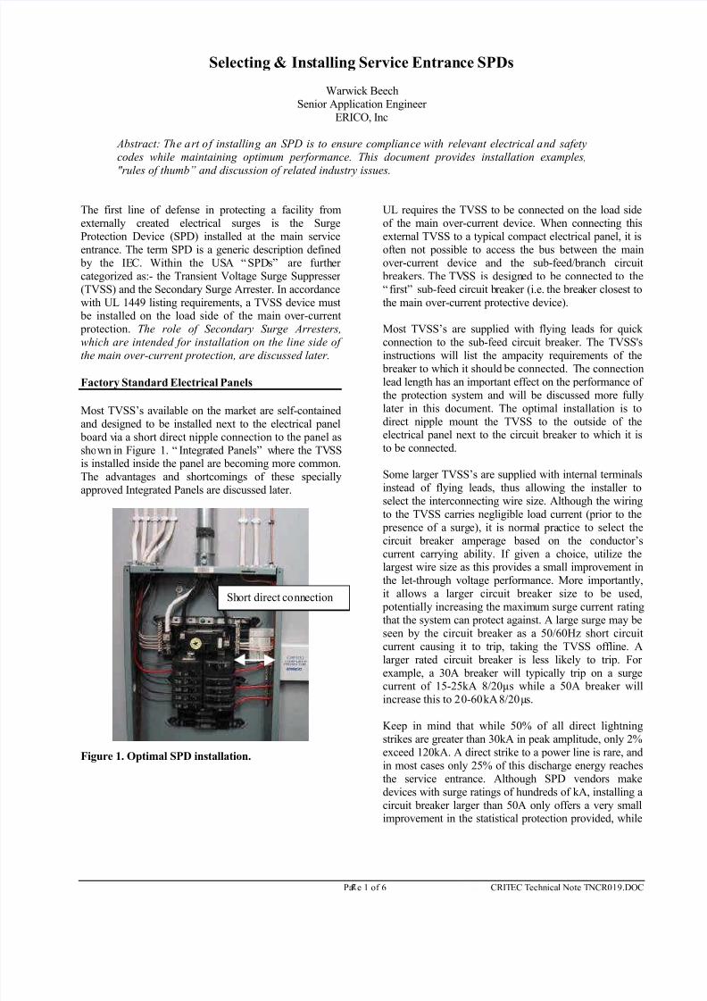
Most TVSS’s available on the market are self-contained
and designed to be installed next to the electrical panel
board via a short direct nipple connection to the panel as
shown in Figure 1. “ Integrated Panels” where the TVSSis installed inside the panel are becoming more common.
The advantages and shortcomings of these specially
approved Integrated Panels are discussed later.
Figure 1. Optimal SPD installation.
UL requires the TVSS to be connected on the load side
of the main over-current device. When connecting this
external TVSS to a typical compact electrical panel, it is
often not possible to access the bus between the main
over-current device and the sub-feed/branch circuit
breakers. The TVSS is designed to be connected to the
“ first” sub-feed circuit breaker (i.e. the breaker closest to
the main over-current protective device).
Most TVSS’s are supplied with flying leads for quick
connection to the sub-feed circuit breaker. The TVSS's
instructions will list the ampacity requirements of the breaker to which it should be connected. The connection
lead length has an important effect on the performance of
the protection system and will be discussed more fully
later in this document. The optimal installation is to
direct nipple mount the TVSS to the outside of theelectrical panel next to the circuit breaker to which it is
to be connected.
Some larger TVSS’s are supplied with internal terminals
instead of flying leads, thus allowing the installer to
select the interconnecting wire size. Although the wiring
to the TVSS carries negligible load current (prior to the
presence of a surge), it is normal practice to select thecircuit breaker amperage based on the conductor’s
current carrying ability. If given a choice, utilize thelargest wire size as this provides a small improvement in
the let-through voltage performance. More importantly,
it allows a larger circuit breaker size to be used,
potentially increasing the maximum surge current rating
that the system can protect against. A large surge may be
seen by the circuit breaker as a 50/60Hz short circuit
current causing it to trip, taking the TVSS offline. A
larger rated circuit breaker is less likely to trip. For
example, a 30A breaker will typically trip on a surgecurrent of 15-25kA 8/20µs while a 50A breaker will
increase this to 20-60kA 8/20µs.
Keep in mind that while 50% of all direct lightning
strikes are greater than 30kA in peak amplitude, only 2%
exceed 120kA. A direct strike to a power line is rare, and
in most cases only 25% of this discharge energy reaches
the service entrance. Although SPD vendors make
devices with surge ratings of hundreds of kA, installing a
circuit breaker larger than 50A only offers a very smallimprovement in the statistical protection provided, while
Short direct connection
7/27/2019 AAA-Selecting & Installing Service Entrance SPDs
http://slidepdf.com/reader/full/aaa-selecting-installing-service-entrance-spds 2/6
Page 2 of 6 CRITEC Technical Note TNCR019.DOC
increasing the risk of not being able to quickly interrupt
an electrical short circuit during fault conditions.
The convenience of using a sub-feed circuit breaker to
make connection to the TVSS also provides an important
advantage. It allows the TVSS unit to be isolated during
maintenance, while the primary supply to the facility is
still maintained.
It is important to adhere to the manufacturer’s
recommendations on wiring size and fusing requirements
as these are generally based on UL’s “conditions of use”
for the particular device’s Listing.
Larger Custom Designed Panels
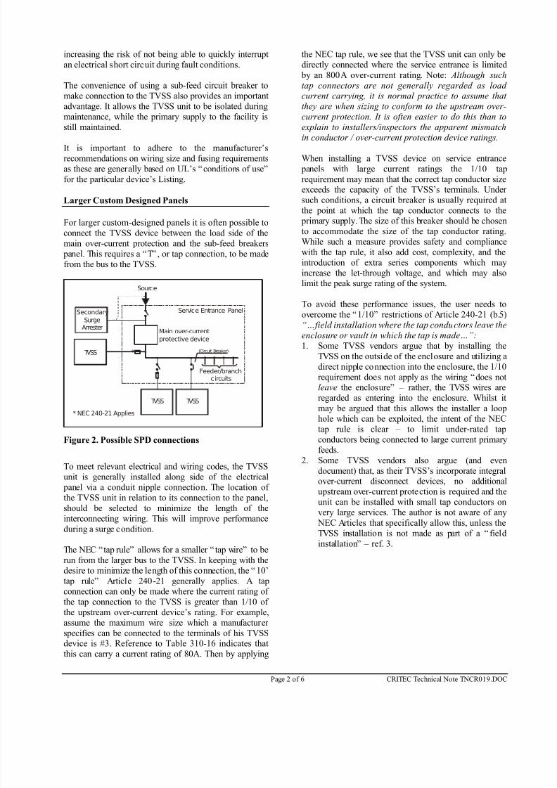
For larger custom-designed panels it is often possible to
connect the TVSS device between the load side of the
main over-current protection and the sub-feed breakers
panel. This requires a “T” , or tap connection, to be made
from the bus to the TVSS.
Service Entrance PanelSecondary
SurgeArrester
TVSS TVSS
TVSS
Source
* NEC 240-21 Applies
(Circuit Breaker)
Main over-current
protective device
*
Feeder/branchcircuits
Figure 2. Possible SPD connections
To meet relevant electrical and wiring codes, the TVSS
unit is generally installed along side of the electrical
panel via a conduit nipple connection. The location of
the TVSS unit in relation to its connection to the panel,
should be selected to minimize the length of the
interconnecting wiring. This will improve performance
during a surge condition.
The NEC “tap rule” allows for a smaller “ tap wire” to berun from the larger bus to the TVSS. In keeping with the
desire to minimize the length of this connection, the “ 10’
tap rule” Article 240-21 generally applies. A tap
connection can only be made where the current rating of
the tap connection to the TVSS is greater than 1/10 of
the upstream over-current device’s rating. For example,
assume the maximum wire size which a manufacturer
specifies can be connected to the terminals of his TVSSdevice is #3. Reference to Table 310-16 indicates that
this can carry a current rating of 80A. Then by applying
the NEC tap rule, we see that the TVSS unit can only be
directly connected where the service entrance is limited
by an 800A over-current rating. Note: Although such
tap connectors are not generally regarded as load current carrying, it is normal practice to assume that
they are when sizing to conform to the upstream over-
current protection. It is often easier to do this than to
explain to installers/inspectors the apparent mismatch
in conductor / over-current protection device ratings.
When installing a TVSS device on service entrance
panels with large current ratings the 1/10 tap
requirement may mean that the correct tap conductor sizeexceeds the capacity of the TVSS’s terminals. Under
such conditions, a circuit breaker is usually required at
the point at which the tap conductor connects to the
primary supply. The size of this breaker should be chosen
to accommodate the size of the tap conductor rating.
While such a measure provides safety and compliance
with the tap rule, it also add cost, complexity, and the
introduction of extra series components which may
increase the let-through voltage, and which may alsolimit the peak surge rating of the system.
To avoid these performance issues, the user needs to
overcome the “1/10” restrictions of Article 240-21 (b.5)
“…field installation where the tap conductors leave the
enclosure or vault in which the tap is made…”:
1. Some TVSS vendors argue that by installing the
TVSS on the outside of the enclosure and utilizing a
direct nipple connection into the enclosure, the 1/10
requirement does not apply as the wiring “does notleave the enclosure” – rather, the TVSS wires are
regarded as entering into the enclosure. Whilst it
may be argued that this allows the installer a loop
hole which can be exploited, the intent of the NEC
tap rule is clear – to limit under-rated tap
conductors being connected to large current primary
feeds.
2. Some TVSS vendors also argue (and even
document) that, as their TVSS’s incorporate integralover-current disconnect devices, no additional
upstream over-current protection is required and the
unit can be installed with small tap conductors on
very large services. The author is not aware of any
NEC Articles that specifically allow this, unless the
TVSS installation is not made as part of a “ field
installation” – ref. 3.
7/27/2019 AAA-Selecting & Installing Service Entrance SPDs
http://slidepdf.com/reader/full/aaa-selecting-installing-service-entrance-spds 3/6
Page 3 of 6 CRITEC Technical Note TNCR019.DOC
3. If the installation of a TVSS unit is not carried out
as part of a field exercise, as may be the case when
switchboard builder incorporates the unit as acomponent within an electrical panel assembly,
Article 240-21 (b.5) is not applicable and Section
2.b allows the tap to be installed on any current
rated service, provided that the tap conductors are
matched to the rating of the TVSS’s internal over-
current protection.
Rather than exploiting loose interpretations of the 1/10
rule to avoid upstream over-current protection, it is
recommended that upstream over-current protection be provided at the point the conductors receive their
supply. This safer approach may however introduce
another complication. The NEC mandates a maximum of
6 disconnects off any one primary service feed (Article
230-71). A connection of a TVSS device to this feed is
included in this count. When this limitation is
encountered, the installation of the TVSS device is
normally relegated to connection on the load side of one
of the existing 6 "disconnects". A proposal to exempt theTVSS connection from this maximum of 6 connection
has been submitted for the 2005 edition of the NEC.
Integrated Panels – TVSS’s installed with in the Panel
A growing trend within the industry is the integration of
TVSS devices within the electrical panel itself, usually by the panel OEM. This practice has recently lead to
panel manufacturers acquiring TVSS manufacturers in
an attempt to increase their competency and market
opportunity in this area. The potential advantages to the
engineer, installer and owner of such integration, are:
§ Simplification of the specification process
§ Reduction in the number of vendors for supply and
support
§ Simplification of installation
§ Improved performance This said, integrated protection panels may also present
their own deficiencies. Installing the TVSS within the
electrical enclosure should ensure shorter connection
lead lengths and an improvement in the let-through
voltage performance. However, this is often not the case.
The TVSS devices are often mounted at the bottom of
the standard can, and connected to feed-through lugs.
This can increase the lead length, resulting in a muchhigher let-through voltage to the equipment connected to
the upper circuit breakers. A performance degradation of
300-500V is possible, increasing the net let-through
voltage to the point where electronic equipment may be
damaged or severely stressed.
§ The panel extension kit may block the ability to feed
cables through the bottom of the electrical
enclosure.
§ If the TVSS is connected directly to the bus, the
entire panel and its load will need to be shut down
to allow replacement of a failed TVSS unit.Conversely, an external TVSS unit connected to a
dedicated breaker, will allow only that circuit to be
disconnected during service.
§ Generally the TVSS technology integrated by panel
manufacturers is less advanced than that
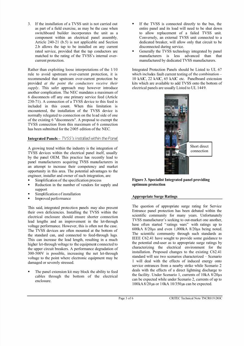
manufactured by dedicated TVSS manufacturers. Integrated Protection Panels should be Listed to UL 67
which includes fault current testing of the combination –
10 kAIC, 22 kAIC, 65 kAIC etc. Panelboard extensionkits which are available to add TVSS onto the bottom of
electrical panels are usually Listed to UL 1449.
Figure 3. Specialist Integrated panel providing
optimum protection
Appropriate Surge Ratings The question of appropriate surge rating for Service
Entrance panel protection has been debated within the
scientific community for many years. Unfortunately
TVSS manufacturer’s seeking to out-market one another,
have often started “ ratings wars” with ratings up to600kA 8/20µs and even 1,000kA 8/20µs being noted.
The scientific community through such standards as
IEEE C62.41 have sought to provide some guidance to
the potential end-user as to appropriate surge ratings bycharacterizing the electrical environment for the
installation. Proposed changes to the existing C62.41
standard will see two scenarios characterized – Scenario
1 will deal with the effects of induced energy onto
service entrances from a nearby strike while Scenario 2deals with the effects of a direct lightning discharge to
the facility. Under Scenario 1, currents of 10kA 8/20µs
can be expected while under Scenario 2, currents of up to
100kA 8/20µs or 10kA 10/350µs can be expected.
Short direct
connection
7/27/2019 AAA-Selecting & Installing Service Entrance SPDs
http://slidepdf.com/reader/full/aaa-selecting-installing-service-entrance-spds 4/6
Page 4 of 6 CRITEC Technical Note TNCR019.DOC
These specifications are intended to provide a much
needed “reality check” to those ratings been promulgated by various TVSS manufacturers. A typical rating of
100kA for a service entrance device already includes a
safety margin and the only practical reason in requiring a
higher rating would be to provide a longer service life.
With each doubling of surge rating, for the same number
and amplitude of transients, “ life” can be increased by afactor of 5-10 times. Value engineering principles point
to a rating of between 100 to 200kA 8/20µs as being
both practical and cost effective. The need for a surge
rating of 600kA with the claimed typical life expectancyof 500 years is questionable. Another problem commonly encountered in the
specification of surge ratings for TVSS devices, is the
practice of claiming a rating based solely on the
aggregate of MOV (or SAD) material contained within
the device. In reality, the single shot capacity of the
device may be significantly less than this due to the
limitations of PCB fuse tracks, thermal of over-currentdisconnect devices and terminals used. NEMA LS-1 has
sought to address this concern by recommending that
manufacturers only claim maximum single shot ratings
based on actual test results. Ideally, a device should be
rated by providing both i) its maximum single shot
capacity (tested) and ii) its aggregate surge capacity
(surge material). Such dual ratings better define the
device’s performance and life characteristics. Note: Often the failure of a TVSS device is attributed tothe number or amplitude of diverted surges, whereas
most failures are the result of temporary over-voltages.
Even so, some well-known TVSS manufacturers
continue to provide TVSS’s with Maximum Continuous
Operating Voltages (MCOV) just over 10% of nominal.
10% above nominal is the continuous limit tested by
UL; anything above this is allowed to safely fail . Many
TVSS manufacturers provide MCOV rating with a more
practical 25% limit, while hybrid technologies are nowavailable that provide even larger MCOVs – without the
traditional cost of increased let-through voltage. TVSS’s and Secondary Surge Arresters The 1999 edition of the NEC defines the application of
Surge Arresters and requires all such devices to be listed.
UL differentiates between Transient Voltage Surge
Suppressors and Secondary Surge Arresters:
§ Transient Voltage Surge Suppressors are tested to
UL 1449 and this document limits their scope of use on the load side of the main over-current
disconnect. They should not be used on the line side.
§ Secondary Surge Arresters are also listed by UL and
are intended for use on the line side of the main
over-current protection. Note: a loophole currently
exists which allows Secondary Surge Arresters to
also be used on the load side of the main over-
current disconnect, however the 2002 Edition of the
NEC under Article 285 seeks to better address this problem.
It should be noted that it is possible for a manufacturer
to complementary list an SPD as both a TVSS device as
well as a Secondary Surge Arrester.
Secondary Surge Arresters are tested to less demanding
safety standards and are generally lower performance
products. These devices were originally intended to
protect power system insulation from flash-overs and notto protect load-side sensitive electronic equipment from
damaging transient voltages. Unfortunately, some
manufacturers have sought to capitalize on this loophole
and provide the cheaper Secondary Surge Arresters in
locations where the intent is that TVSS devices, with
their more stringent test requirements, are intended. .
While most installers and inspectors are accustomed to
checking installed devices for the presence of an
approved Listing logo, few are experienced with thesubtleties of SPDs to correctly differentiate between a
Secondary Surge Arrester and a TVSS device.
The question regarding the need for both Secondary
Surge Arresters and TVSS devices to be installed on a
facility, is often raised. Accepted practice often utilizes
both of these devices. A secondary Surge Arrester may be
installed at the primary service entrance or power pole as
the first line of defense and a TVSS device close to the
equipment actually being protected. This second devicealso provides protection against the more common
smaller transients that are generated within the facility
itself by electrical equipment.
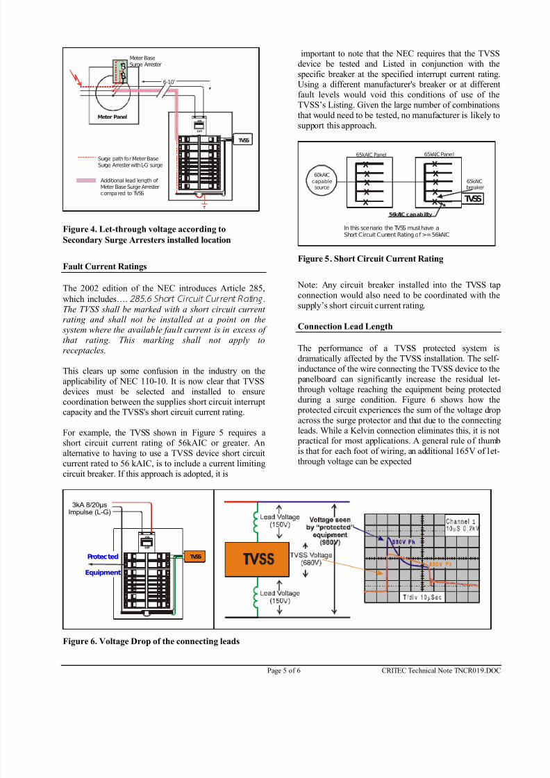
A question often asked is whether a Secondary Surge
Arrester installed at the meter socket eliminates the need
for TVSS protection at the Service Entrance Panel.
Figure 4 illustrates the voltage that is added to a meter
socket device’s performance due to its connectionmethod. In practice, the situation will be much worse as
the Secondary Surge Arrester used here is generally a
poorer performing device than a TVSS installed at the
panel. In a typical installation with 8 feet of wiring
between the meter socket and the Service Entrance panel,
a difference in let-through voltage of between 2,000 and
3,000 volts is possible.
7/27/2019 AAA-Selecting & Installing Service Entrance SPDs
http://slidepdf.com/reader/full/aaa-selecting-installing-service-entrance-spds 5/6
Page 5 of 6 CRITEC Technical Note TNCR019.DOC
ON
OFF
TVSS
Meter Panel
Meter BaseSurge Arrester
6-10’
Surge path for Meter BaseSurge Arrester with L-G surge
Additional lead length of Meter Base Surge Arrestercompared to TVSS
Figure 4. Let-through voltage according to
Secondary Surge Arresters installed location
Fault Current Ratings
The 2002 edition of the NEC introduces Article 285,
which includes…. 285.6 Short Ci rcuit Cur rent Rating .
The TVSS shall be marked with a short circuit current rating and shall not be installed at a point on the
system where the available fault current is in excess of
that rating. This marking shall not apply to
receptacles.
This clears up some confusion in the industry on the
applicability of NEC 110-10. It is now clear that TVSS
devices must be selected and installed to ensure
coordination between the supplies short circuit interrupt
capacity and the TVSS's short circuit current rating.
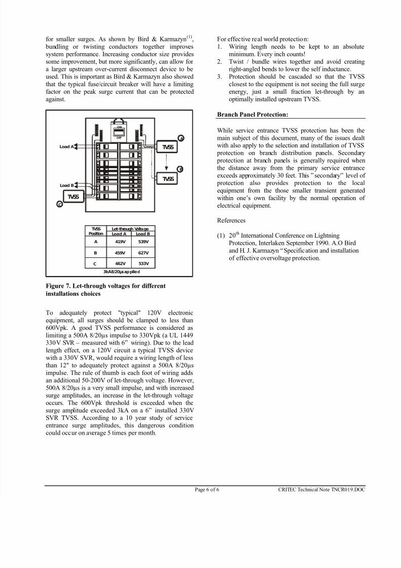
For example, the TVSS shown in Figure 5 requires a
short circuit current rating of 56kAIC or greater. An
alternative to having to use a TVSS device short circuit
current rated to 56 kAIC, is to include a current limiting
circuit breaker. If this approach is adopted, it is
important to note that the NEC requires that the TVSS
device be tested and Listed in conjunction with the
specific breaker at the specified interrupt current rating.Using a different manufacturer's breaker or at different
fault levels would void this conditions of use of the
TVSS’s Listing. Given the large number of combinations
that would need to be tested, no manufacturer is likely to
support this approach.
60kAIC
capablesource
X
X
XX
X
X
X
XX
X TVSS
65kAIC Panel65kAIC Panel
65kAICbreaker
56kAIC capability
In this scenario the TVSS must have aShort Circuit Current Rating of >=56kAIC
Figure 5. Short Circuit Current Rating
Note: Any circuit breaker installed into the TVSS tap
connection would also need to be coordinated with the
supply’s short circuit current rating.
Connection Lead Length
The performance of a TVSS protected system is
dramatically affected by the TVSS installation. The self-
inductance of the wire connecting the TVSS device to the
panelboard can significantly increase the residual let-
through voltage reaching the equipment being protected
during a surge condition. Figure 6 shows how the
protected circuit experiences the sum of the voltage dropacross the surge protector and that due to the connecting
leads. While a Kelvin connection eliminates this, it is not practical for most applications. A general rule of thumb
is that for each foot of wiring, an additional 165V of let-
through voltage can be expected
ON
OFF
TVSSProtected
Equipment
3kA 8/20µsImpulse (L-G)
Figure 6. Voltage Drop of the connecting leads
7/27/2019 AAA-Selecting & Installing Service Entrance SPDs
http://slidepdf.com/reader/full/aaa-selecting-installing-service-entrance-spds 6/6
Page 6 of 6 CRITEC Technical Note TNCR019.DOC
for smaller surges. As shown by Bird & Karmazyn(1)
,
bundling or twisting conductors together improves
system performance. Increasing conductor size providessome improvement, but more significantly, can allow for
a larger upstream over-current disconnect device to be
used. This is important as Bird & Karmazyn also showed
that the typical fuse/circuit breaker will have a limiting
factor on the peak surge current that can be protected
against.
ON
OFF
TVSS
TVSS
TVSS
Load A
Load B
A
B
C
TVSSPosition
Let-through Voltage
A
B
C
Load A Load B
3kA 8/20µs applied
419V 539V
459V 627V
462V 533V
Figure 7. Let-through voltages for different
installations choices
To adequately protect "typical" 120V electronic
equipment, all surges should be clamped to less than
600Vpk. A good TVSS performance is considered as
limiting a 500A 8/20µs impulse to 330Vpk (a UL 1449330V SVR – measured with 6” wiring). Due to the lead
length effect, on a 120V circuit a typical TVSS device
with a 330V SVR, would require a wiring length of less
than 12" to adequately protect against a 500A 8/20µs
impulse. The rule of thumb is each foot of wiring adds
an additional 50-200V of let-through voltage. However,
500A 8/20µs is a very small impulse, and with increased
surge amplitudes, an increase in the let-through voltageoccurs. The 600Vpk threshold is exceeded when the
surge amplitude exceeded 3kA on a 6” installed 330VSVR TVSS. According to a 10 year study of service
entrance surge amplitudes, this dangerous condition
could occur on average 5 times per month.
For effective real world protection:
1. Wiring length needs to be kept to an absolute
minimum. Every inch counts!2. Twist / bundle wires together and avoid creating
right-angled bends to lower the self inductance.
3. Protection should be cascaded so that the TVSS
closest to the equipment is not seeing the full surge
energy, just a small fraction let-through by an
optimally installed upstream TVSS.
Branch Panel Protection:
While service entrance TVSS protection has been the
main subject of this document, many of the issues dealtwith also apply to the selection and installation of TVSS
protection on branch distribution panels. Secondary
protection at branch panels is generally required when
the distance away from the primary service entrance
exceeds approximately 30 feet. This ” secondary” level of
protection also provides protection to the local
equipment from the those smaller transient generated
within one’s own facility by the normal operation of electrical equipment.
References
(1) 20th
International Conference on Lightning
Protection, Interlaken September 1990. A.O Bird
and H. J. Karmazyn “Specification and installation
of effective overvoltage protection.


![arranged by tom wallace percussion by tony mccutchen 11 a a 10 aaa > e] aa aaa 6 aaa aaa aaa aaa aaa aaa 13 > 19 — 18 15 a a aa 16 a a 12 20 23 a > 24 aaa > 25 a > 26 aaa > 27 gÆ4k](https://img.pdfslide.us/doc/110x75/5e6c4dfc8bd84b079d5a5076/arranged-by-tom-wallace-percussion-by-tony-mccutchen-11-a-a-10-aaa-e-aa-aaa.jpg)