Embed Size (px)
Citation preview

Page 1 of 26 Company ConfidentialVersion 1.0
The AA Ltd
AA Signs Division
Installation Documentation
Peugeot Boxer

Page 2 of 26 The AA Signs– Company ConfidentialVersion 1.0
Overview
The Signs division of The AA Ltd require Trakm8 to provide a telematics solution that will monitor, collate and stream data including:
CANbus data to show fuel usageBeacons– input zero to monitor when the beacons are operationalGreen/red switch enclosure – input 1 and input 2 to monitor when sign(s) deployed and collectedGPS trackingDriver Feedback
Please note that driver identification (dallas key) is no longer required on The AA Signs. Disconnect the driver id receiver from the
T8 premium wiring loom (2 molex connectors) but DO NOT remove it from the vehicle panel.
This document has been produced to provide exact instructions on how this equipment is to be installed, input location and any interfaces have been agreed with The AA Ltd and under no circumstances should be deviated from without written permission.
Please note that you are not insured to drive / move The AA Ltd vehicle during the installation process.
Ensure the ignition remains switched OFF at all times during the installation. Any connections made with power to the Trakm8
unit will cause faults on the vehicle ECU.

Hardware required for Peugeot Boxer
• Trakm8 T8
• Premium Wiring Loom
• GPS Antenna
• Fuse Kit (2 x Holder + 1 Amp and 2 Amp fuse)
• T-Piece
• T-Piece Bracket
• T-Piece CAN Extension Cable
Hardware continued on page 4
Page 3 of 26
Hardware for Peugeot Boxer
The AA Signs– Company ConfidentialVersion 1.0
Trakm8 Install Peugeot Boxer
Hardware required for Peugeot Boxer
• Push button enclosure
- GREEN (Deployed)
- RED (Collected)
• Single LED Driver Feedback Module
• Buzzer
• 1K Resistor
Page 4 of 26
Hardware for Peugeot Boxer
The AA Signs– Company ConfidentialVersion 1.0
Trakm8 Install Peugeot Boxer

Complete kit
(Pre-installation)
K-line
Trakm8 CANbus (T-Piece) Install
Page 5 of 26 Version 1.0 The AA Signs– Company Confidential
This image shows the wires required for installation (Also see wiring notes on page 25)
• Red = Live (12volts on vehicle)
• Blue = Ignition on vehicle
• Black = Earth to a chassis bolt on vehicle
• White/Black = K-Line

The purpose of this information is to provide a guide and specification for the installation of the TrakM8 telematics unit into a Peugeot Boxer.
This instruction is specific to the Peugeot Boxer.
Page 6 of 26
Purpose Of Information
The AA Signs– Company ConfidentialVersion 1.0
Trakm8 Install Peugeot Boxer

The key points are:
• GPS Antenna/Buzzer location
• Driver Feedback Module
• Push button enclosure
• Main TCU location above main fuse-board
• Power pickup points from main fuse board behind driver side panel
• CANbus pickup points from OBD socket
Page 7 of 26
Overview
The AA Signs– Company ConfidentialVersion 1.0
Trakm8 Install Peugeot Boxer

• Remove 2 philips screws from the lower panel to gain access to the fuse board.
• Remove 1 philips screw to remove coin tray.
• The OBD socket is located within the face of the fuseboard.
• PLEASE NOTE – the vehicle OBD socket cannot be removed
Page 8 of 26
Locate the vehicle OBD socket
The AA Signs– Company ConfidentialVersion 1.0
Trakm8 Install Peugeot Boxer

• Connect the T-Piece to the vehicle OBD socket as shown.
• Ensure that the OBD socket locates firmly into the T-Piece.
• NB: The T-Piece CAN extension cable shown alongside the connector is part of the Trakm8 loom and must be routed with the OBD cable to the Main TCU
Page 9 of 26
Attach the T-Piece to the vehicle OBD
socket
The AA Signs– Company ConfidentialVersion 1.0
Trakm8 Install Peugeot Boxer
1
2

• Secure the T-Piece with cable ties to existing vehicle looms.
• Place the T-Piece OBD socket into the bracket supplied.
• The T-Piece bracket is held in place against the metal lip on the right hand side of the fuse board.
• Secure with double sided tape.
Page 10 of 26
Secure the T-Piece to the bracket
The AA Signs– Company ConfidentialVersion 1.0
Trakm8 Install Peugeot Boxer
Cable Ties
Double Sided
Tape
1
2
Page 11 of 26 Version 1.0 The AA Signs– Company Confidential
Trakm8 Install Peugeot Boxer
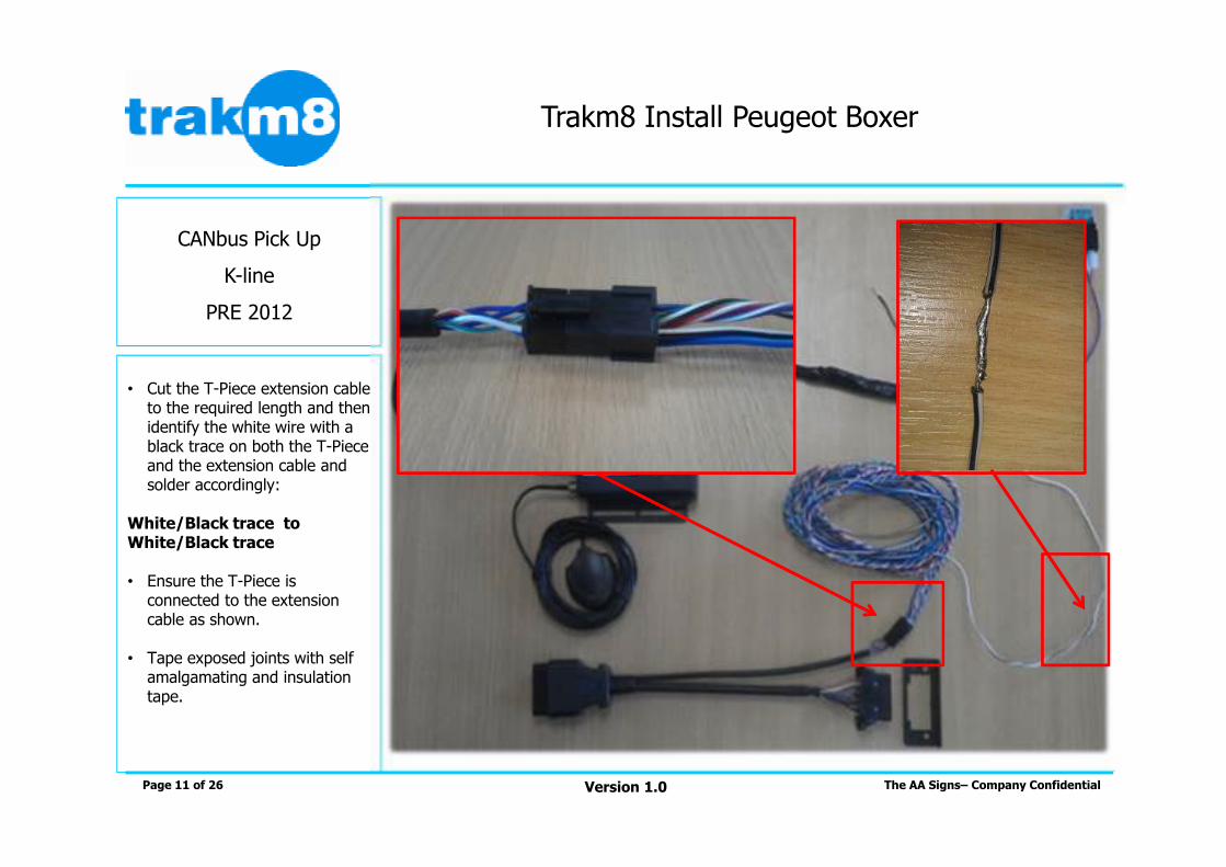
CANbus Pick Up
K-line
PRE 2012
• Cut the T-Piece extension cable to the required length and then identify the white wire with a black trace on both the T-Piece and the extension cable and solder accordingly:
White/Black trace to White/Black trace
• Ensure the T-Piece is connected to the extension cable as shown.
• Tape exposed joints with self amalgamating and insulation tape.
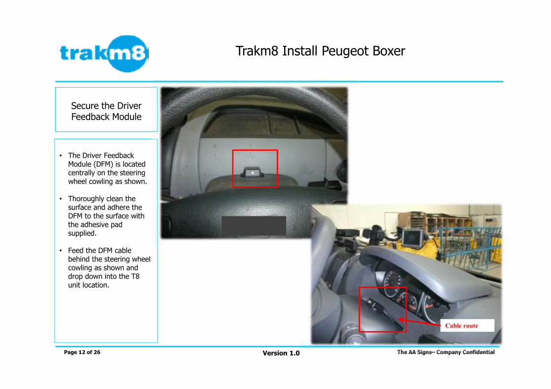
• The Driver Feedback Module (DFM) is located centrally on the steering wheel cowling as shown.
• Thoroughly clean the surface and adhere the DFM to the surface with the adhesive pad supplied.
• Feed the DFM cable behind the steering wheel cowling as shown and drop down into the T8 unit location.
Page 12 of 26
Secure the Driver Feedback Module
The AA Signs– Company ConfidentialVersion 1.0
Trakm8 Install Peugeot Boxer
Cable route

• Attach DFM Molex connectors to the corresponding female Molex connectors the T8 main loom:
BLACK/WHITE to BLACK/WHITEBLACK/BROWN to BLACK/BROWN
• Neatly store any excess cable alongside the unit.
Page 13 of 26
Connect the DFM to the Trakm8 Unit
The AA Signs– Company ConfidentialVersion 1.0
Trakm8 Install Peugeot Boxer

• The GPS antenna is secured behind the driver instrument panel.
• Remove two T20 torxscrews as shown. The screws are front facing either side of the clocks.
• Secure the GPS antenna in place with double sided tape.
Page 14 of 26
GPS AntennaMounting
The AA Signs– Company ConfidentialVersion 1.0
Trakm8 Install Peugeot Boxer
T20 torx screws
1
2
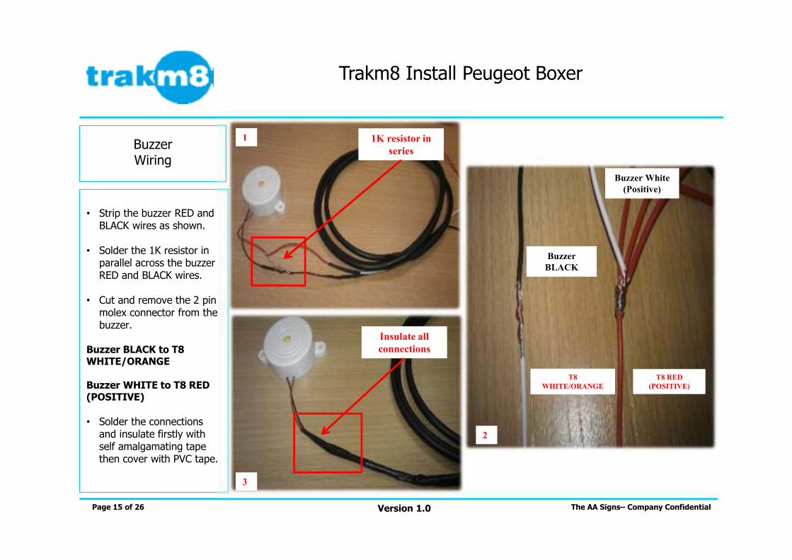
• Strip the buzzer RED and BLACK wires as shown.
• Solder the 1K resistor in parallel across the buzzer RED and BLACK wires.
• Cut and remove the 2 pin molex connector from the buzzer.
Buzzer BLACK to T8 WHITE/ORANGE
Buzzer WHITE to T8 RED (POSITIVE)
• Solder the connections and insulate firstly with self amalgamating tape then cover with PVC tape.
Page 15 of 26
BuzzerWiring
The AA Signs– Company ConfidentialVersion 1.0
Trakm8 Install Peugeot Boxer
1K resistor in
series
Buzzer
BLACK
T8
WHITE/ORANGE
T8 RED
(POSITIVE)
Buzzer White
(Positive)
Insulate all
connections
1
2
3

• The buzzer is secured behind the driver instrument panel.
• Secure in place with double sided tape.
• Place a small piece of PVC insulation tape across the top of the buzzer hole.
• The buzzer will give an audible tone which will vary for green and red button press:
GREEN (Sign Deployed) = 1 second beep
RED (Sign Collected) = 1 second trill
Page 16 of 26
BuzzerMounting
The AA Signs– Company ConfidentialVersion 1.0
Trakm8 Install Peugeot Boxer
1
2

• The pushbutton enclosure records when a driver has collected and deployed the signs. Ensure that wires are not transposed.
• GREEN (SIGNS DEPLOYED) = GREY to T8 BLUE/WHITE
• RED (SIGNS COLLECTED) = GREEN to T8 GREY
• GREEN AND RED SWITCH POSITIVE = RED to T8 RED
• Solder the connections and insulate firstly with self amalgamating tape then cover with PVC tape.
Page 17 of 26
Button Enclosure Wiring
The AA Signs– Company ConfidentialVersion 1.0
Trakm8 Install Peugeot Boxer
T8 Grey
(Input 1)
T8 Blue/White
(Input 2)
T8 Red
(Positive)
RED switch
GREEN
RED and
GREEN switch
Positive
GREEN
switch GREY
1
2

• Remove 1 T20 torx screw on the underside of the air vent. Remove the air vent and store in a safe place.
• The pushbutton enclosure is positioned facing the driver as shown.
• Thoroughly clean the surface and adhere the pushbutton enclosure to the surface with the adhesive pad supplied.
• Feed the enclosure cable into the lower panel and re-fit the air vent.
Page 18 of 26
Pushbutton Enclosure Mounting
The AA Signs– Company ConfidentialVersion 1.0
Trakm8 Install Peugeot Boxer
Cable behind air
vent

• Identify the beacons cable that runs within the storage shelf located in the back of the vehicle.
• The beacons wire is in the 2 core cable that runs to the beacons side light above the driver side door.
BEACONS RED to T8 PURPLE (Input 0)
• Extend the beacons wire to the T8 at the front of the vehicle.
Page 19 of 26
Beacon Cable route
The AA Signs– Company ConfidentialVersion 1.0
Trakm8 Install Peugeot Boxer
1 2
3

• Remove the A pillar side trim and disconnect the speaker connector shown.
• Drop the extended wire from the beacons pickup into the cab area and feed along the headlining to the A pillar.
• Solder the connection and insulate firstly with self amalgamating tape then cover with PVC tape.
Page 20 of 26
Beacon Cable route
The AA Signs– Company ConfidentialVersion 1.0
Trakm8 Install Peugeot Boxer
1
2
3
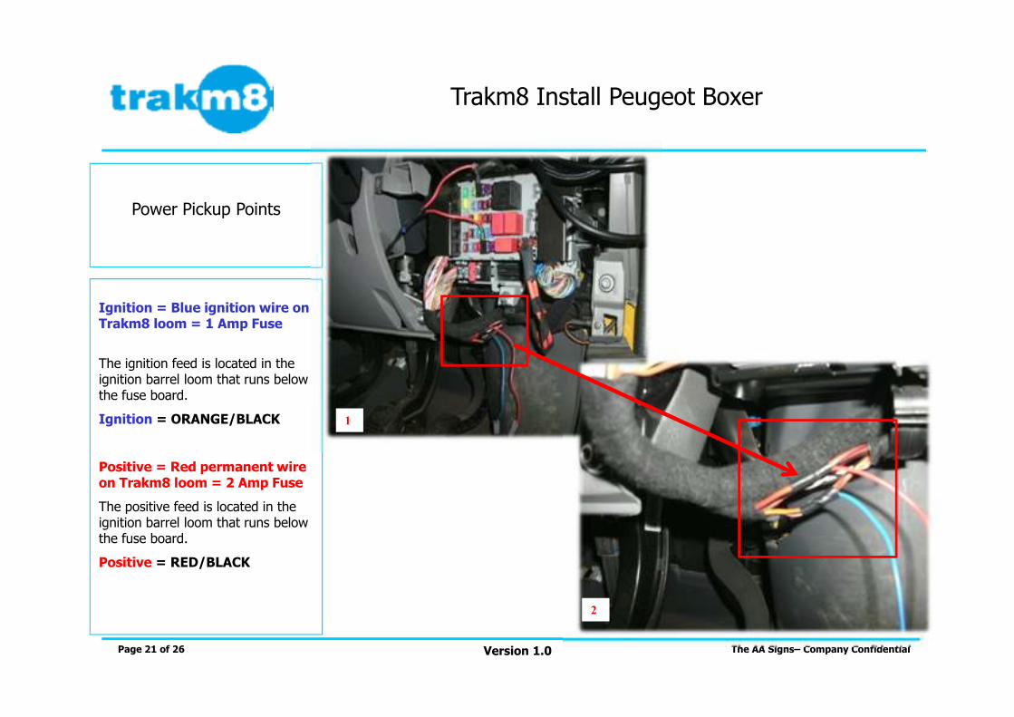
Ignition = Blue ignition wire on Trakm8 loom = 1 Amp Fuse
The ignition feed is located in the ignition barrel loom that runs below the fuse board.
Ignition = ORANGE/BLACK
Positive = Red permanent wire on Trakm8 loom = 2 Amp Fuse
The positive feed is located in the ignition barrel loom that runs below the fuse board.
Positive = RED/BLACK
Page 21 of 26
Power Pickup Points
The AA Signs– Company ConfidentialVersion 1.0
Trakm8 Install Peugeot Boxer
1
2

12Volt Positive = Red permanent wire on TM8 loom True Ignition = Blue ignition wireon TM8 loom
Ignition = 12Volts on engine running and 0Volts on phase 2 ignition engine off. If it is not possible to gain access to this wire then 12Volts on stage 2 ignition without engine running is secondary
The fuse holder should be located as close as possible to the power ‘pick – up’ point as possible. (Ideally no less than 4 inches). Correct fuse ratings must always be used.
Page 22 of 26
Power Pick Up Connections
The AA Signs– Company ConfidentialVersion 1.0
Trakm8 Install Peugeot Boxer

• Negative = Black earth wire on Trakm8 loom
• Connect the earth/negative wire (Black) of the Trakm8 loom to the 10 mm allenkey screw adjacent to the fuse-box as shown.
Please use a 10 mm ring terminal ensuring a good connection is made.
Page 23 of 26
Earth/Negative Connection
The AA Signs– Company ConfidentialVersion 1.0
Trakm8 Install Peugeot Boxer

• The main Trakm8 TCU location is above the fuse board.
• Use the existing vehicle 10mm allen key screw to secure the unit in place with the T8 label facing towards you.
• Mount the unit EXACTLYas shown. The unit has an internal accelerometer so secure mounting of the unit is important.
Page 24 of 26
Main Trakm8 unit location
The AA Signs– Company ConfidentialVersion 1.0
Trakm8 Install Peugeot Boxer

Trakm8 Install Peugeot Boxer
Version 1.0 The AA Signs– Company ConfidentialPage 25 of 26
• All wires not used on the T8 loom are to be cut to different lengths (staggered and not touching) and then wrapped using electrical insulation tape
• All soldered connections are also required to be wrapped securely using electrical insulation tape
• Cables not used and long lengths, should be stowed neatly and secured using electrical tape as shown in this image.
• Power supply is not to be taken from the OBD socket!
Wiring Notes

Trakm8 Install Peugeot Boxer
Version 1.0 The AA Signs– Company ConfidentialPage 26 of 26
Commissioning and Completion of Installation
• Before contacting Trakm8 to commission the unit start the engine. When the unit has powered up and 3 green trills (GPRS) and 3 green flashes (GPS) have been observed, operate the beacons and pushbuttons to generate an events.
• Please have the following information available for the Trakm8 commissioning team. This will make the process quicker if these details are at hand:
Unit imei (this is the 15 digit serial number across the Trakm8 unit)Vehicle registrationOdometer reading
• You will be asked to observe the Driver Feedback Display while the engine is idling. This is to confirm the LED status runs through the GREEN-AMBER-RED status in the correct order.
• When Trakm8 have finished commissioning the unit and confirmed location, CANbus data, beacons switching high/low, pushbutton (sign deployed and collected) events and idling is observed you will then be issued with a unique commissioning number.
• The vehicle can now be rebuilt checking all panels are fitted correctly and all waterproof seals are in place. Please ensure that the vehicle is left in a clean and tidy manner with all cable tie ends and cable snips removed from the vehicle.
A vehicle post installation check should now be completed to check vehicle functions.