Embed Size (px)
Citation preview

USER MANUAL8300 MkII Sound Reception System
MARITIME: COMMUNICATION SYSTEMS A100K11918
About this Document
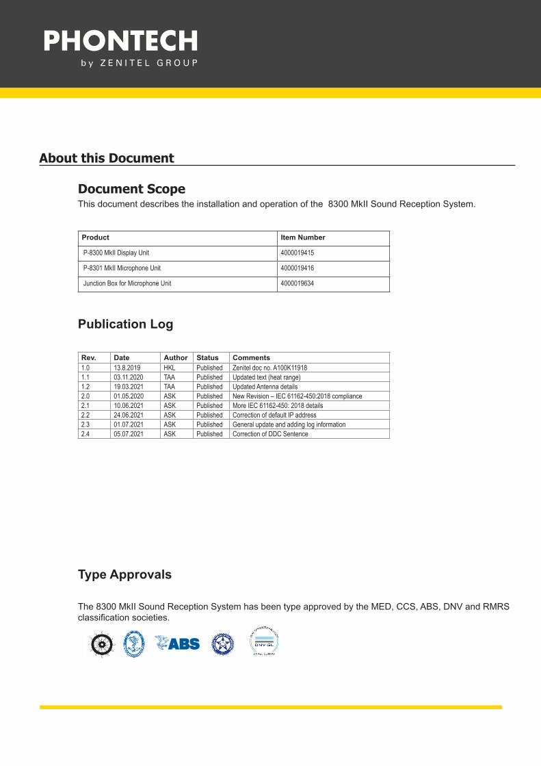
Document ScopeThis document describes the installation and operation of the 8300 MkII Sound Reception System.
Product Item Number
P-8300 MkII Display Unit 4000019415
P-8301 MkII Microphone Unit 4000019416
Junction Box for Microphone Unit 4000019634
Publication Log
Rev. Date Author Status Comments1.0 13.8.2019 HKL Published Zenitel doc no. A100K119181.1 03.11.2020 TAA Published Updated text (heat range)1.2 19.03.2021 TAA Published Updated Antenna details2.0 01.05.2020 ASK Published New Revision – IEC 61162-450:2018 compliance2.1 10.06.2021 ASK Published More IEC 61162-450: 2018 details2.2 24.06.2021 ASK Published Correction of default IP address 2.3 01.07.2021 ASK Published General update and adding log information2.4 05.07.2021 ASK Published Correction of DDC Sentence
Type Approvals
The 8300 MkII Sound Reception System has been type approved by the MED, CCS, ABS, DNV and RMRS classification societies.

CONTENTAbbreviations 5
General 6
Standards 6
1 Product Description 7
2 System Description 8
3 Technical Specifications 9
3.1 Product Specification P-8300 MkII Display Unit 93.2 Product Specification P-8301 MkII Microphone Unit 113.3 Product Specification Junction Box 13
4 Installation 14
4.1 P-8301 MkII Microphone Unit 144.2 P-8300 MkII Display Unit 154.3 Electrical Connections 16
5 Operating Instructions 18
5.1 Operational Modes 18
5.1.1 Normal Mode 185.1.2 Manual Listen Mode 195.1.3 Calibration Detection Mode 205.1.4 LED Test Mode 20
5.2 Network Operations 21
5.2.1 PJTR Sentence 225.2.2 DDC Sentence 245.2.3 SRP Sentence 245.2.4 Maximum Data Rates 25
5.3 Syslog Messages 25
5.3.1 Syslog levels 26
5.4 Audio Packet Stream 265.5 Error Indicator 275.6 Detecting a Sound Signal 275.8 Adjusting Volume and Lighting 295.9 Web Interface 30
5.9.1 Home Screen 305.9.2 Network Settings 325.9.3 Audio Settings 345.9.4 System Log 345.9.5 Additional Options 36

6 Testing 38
6.1 Calibration and Testing 38
7 Maintenance 38
8 Test and Maintenance Records 39
9 Troubleshooting 40
9.1 Microphone Surveillance Failure 409.2 LED Surveillance Failure 409.3 Foghorn Detection Failure 419.4 Display Unit Boot Failure 41
Warranty 41
Warranty Claims 42
Service 42
Spare Parts 42
Recycling & Disposal 42
Support/Contact 42

5
User Manual 8300 MkII Sound Reception System
A100K11918
Abbreviations
CMOS Complementary metal-oxide semi conductor
DDC Display dimming control (sentence)
DHCP Dynamic Host Configuration Protocol
EMC Electromagnetic compatibility
ESD Electrostatic discharge
GMDSS Global Maritime Distress and Safety System
HBT Heartbeat (sentence)
HTTP Hypertext Transfer Protocol
Hz Hertz (unit of frequency)
IC Integrated circuit (system)
IEC International Electrotechnical Commission
IMO International Maritime Organization
IP Internet protocol (address)
ISO The International Organization for Standardization
kB/s Kilobytes per second
kHz Kilohertz
LED Light-emitting diode
MED Marine Equipment Directive
PCM Pulse code modulation
PJTR Zenitel proprietary sentence
RMA Return Material Authorization number
RTCP Real-time Transport Control Protocol
RTP Real-time Transport Protocol
SFI System function ID
SOLAS Safety of Life at Sea
SPL Sound Pressure Level
SRS Sound Reception Signal (proprietary sentence)
TAG Transport, Annotate and Group
UDP User Datagram Protocol
VDC Voltage Direct Current
VOL Volume (proprietary sentence)
6
User Manual 8300 MkII Sound Reception System
A100K11918
GeneralZenitel develops and manufactures professional and state-of-the art products and communication systems for usage on land and at sea. Zenitel supplies products and services that comply with the latest applicable standards. The use of modern test instrumentation and detailed test procedures ensures that you are supplied with quality products.Copies of all Phontech documentation can be downloaded from our website: www.phontech.net
All information contained within this manual has been verified and is correct. However, no responsibility is assumed by Zenitel for inaccuracy. Zenitel reserves the right to make changes to any product(s) or module(s) described herein to improve reliability, function or design, without further notice.
StandardsThe 8300 MkII Sound Reception System has been verified, tested and meets the following product standards:
ISO 14859:2012 Ships and marine technology – Sound reception systems
IEC 60945:2002Maritime navigation and radio communication equipment and systems – General requirements – Methods of testing and required test results.
IEC 61162-1:2016Maritime navigation and radio communication equipment and systems – Digital interfaces – Part 1: Single talker and multiple listeners.
IEC 61162-450:2018Maritime navigation and radio communication equipment and systems – Digital interfaces-Part 450: Multiple talkers and multiple listeners – Ethernet interconnection.
IEC 62288:2014 edition 2Maritime navigation and radio communication equipment and systems – Presentation of navigation – related information on shipborne navigational displays – General requirements, methods of testing and required test results.
8300 MkII also fulfils the following requirements:
SOLAS Chapter V - Safety of navigation- Regulation 19
Carriage requirements for shipborne navigational systems and equipment.
IMO Res. A.694(17)General requirements for shipborne radio equipment forming part of the Global Maritime Distress and Safety System (GMDSS) and for electronic navigational aids.
IMO Res. MSC.36(63) Adoption of the international code of safety for high speed craft (1994).
IMO Res. MSC.86(70) Adoption of new and amended performance standards for navigational equipment.
IMO Res. MSC.97(73) Adoption of the international code of safety for high speed craft (2000).
IMO Res. MSC.191(79)Performance standards for the presentation of navigation-related information on the shipborne navigational displays.
■ NOTE: This product is ship wheel-marked and type approved in accordance with Marine Equipment Directive (MED).
■ NOTE: All statements of conformity are available at: www.phontech.net
7
User Manual 8300 MkII Sound Reception System
A100K11918
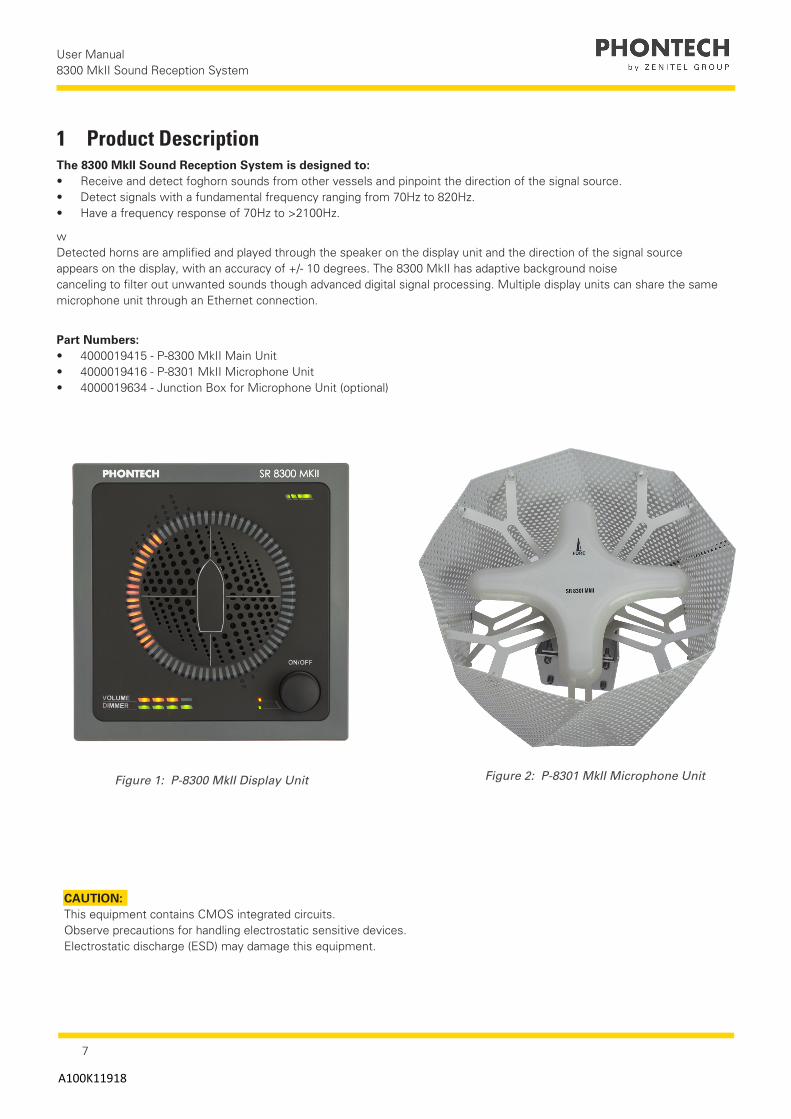
1 Product Description The 8300 MkII Sound Reception System is designed to:• Receive and detect foghorn sounds from other vessels and pinpoint the direction of the signal source.• Detect signals with a fundamental frequency ranging from 70Hz to 820Hz. • Have a frequency response of 70Hz to >2100Hz.
wDetected horns are amplified and played through the speaker on the display unit and the direction of the signal source appears on the display, with an accuracy of +/- 10 degrees. The 8300 MkII has adaptive background noise canceling to filter out unwanted sounds though advanced digital signal processing. Multiple display units can share the same microphone unit through an Ethernet connection.
Part Numbers:• 4000019415 - P-8300 MkII Main Unit• 4000019416 - P-8301 MkII Microphone Unit• 4000019634 - Junction Box for Microphone Unit (optional)
Figure 1: P-8300 MkII Display Unit Figure 2: P-8301 MkII Microphone Unit
CAUTION: This equipment contains CMOS integrated circuits. Observe precautions for handling electrostatic sensitive devices. Electrostatic discharge (ESD) may damage this equipment.

8
User Manual 8300 MkII Sound Reception System
A100K11918
2 System Description A Sound Reception System is an acoustical electronic navigational aid that enables an individual to hear sound signals from other ships like foghorns when standing inside a totally enclosed bridge space, in order to perform the lookout function as required according to the International Regulations for Preventing Collisions at Sea, 1972.
The system works by listening and detecting the direction of a foghorn. The 8300 MkII system is always listening for sounds on the outside of the ship and will only play back and display sounds once a horn has been detected. The vessel's own horn can be suppressed by closing a closing contact on the 8300 MkII system, which will disable detection for the duration it is held closed.
Figure 3: 8300 MkII Sound Reception System
9
User Manual 8300 MkII Sound Reception System
A100K11918
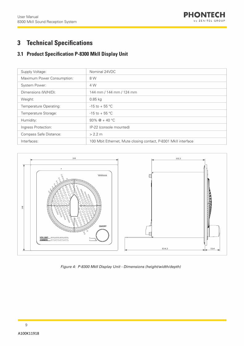
Supply Voltage: Nominal 24VDC
Maximum Power Consumption: 8 W
System Power: 4 W
Dimensions (W/H/D): 144 mm / 144 mm / 124 mm
Weight: 0.85 kg
Temperature Operating: -15 to + 55 °C
Temperature Storage: -15 to + 55 °C
Humidity: 93% @ + 40 °C
Ingress Protection: IP-22 (console mounted)
Compass Safe Distance: > 2.2 m
Interfaces: 100 Mbit Ethernet, Mute closing contact, P-8301 MkII interface
3 Technical Specifications
3.1 Product Specification P-8300 MkII Display Unit
Figure 4: P-8300 MkII Display Unit - Dimensions (height/width/depth)
10
User Manual 8300 MkII Sound Reception System
A100K11918
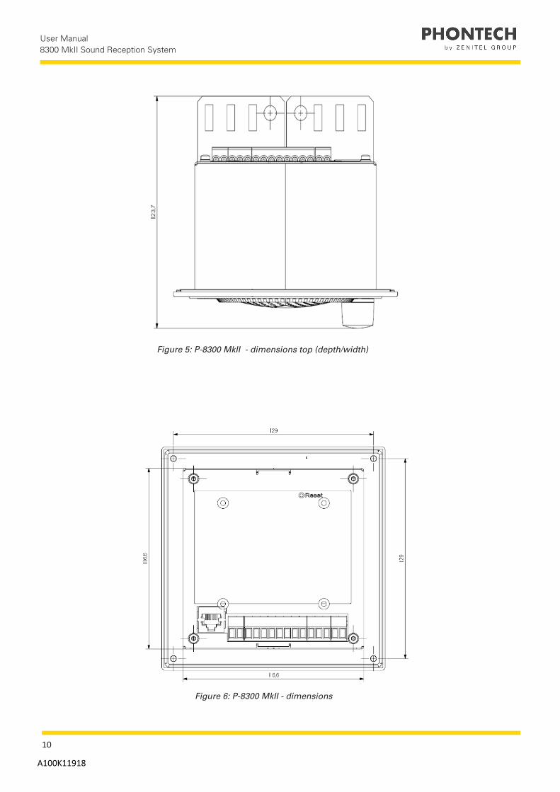
Figure 5: P-8300 MkII - dimensions top (depth/width)
Figure 6: P-8300 MkII - dimensions

11
User Manual 8300 MkII Sound Reception System
A100K11918
3.2 Product Specification P-8301 MkII Microphone Unit
Supply Voltage: Powered by 8300 MkII/+5VDC
Dimensions (W/H/D): 317 mm / 338 mm / 317 mm
Weight: 3.95 kg
Temperature Operating: -60 to + 55 °C
Temperature Storage: -60 to + 70 °C
Humidity: 93% @ + 40 °C
Ingress Protection: IP-56
Compass Safe Distance > 0.3 m
Microphones 4
Antenna Direction Omnidirectional
Figure 7: P-8301 MkII - dimensions (height) Figure 8: P-8301 MkII - dimensions (width)

12
User Manual 8300 MkII Sound Reception System
A100K11918
Figure 10: P-8301 MkII - Mounting Bracket
Figure 9: P-8301 MkII - Dimensions (Mounting Bracket)

13
User Manual 8300 MkII Sound Reception System
A100K11918
3.3 Product Specification Junction Box
Dimensions (W/H/D): 120 mm / 78 mm / 104.5 mm
Weight: 0.35 kg
Ingress Protection: IP-67
Temperature Operating: -50 to + 90 °C
Figure 11: Junction Box - 12-way with screen (optional)

14
User Manual 8300 MkII Sound Reception System
A100K11918
4 Installation
4.1 P-8301 MkII Microphone Unit The microphone unit can be mounted with the attached mounting bracket by fastening the bracket to the ship or removing the bracket and attaching the steel tube by other means.
The mounting bracket can be mounted to a ship on the top or the side.
CAUTION:
The P-8301 MkII should be installed in an appropriate location, bearing the following in mind:• Install the microphone unit in a location far away from noise and any mechanical vibration sources.• The microphone unit should not be installed next to a sound reflective source or obstacle that may block sound from
entering it in a straight line.
NOTE:
Zenitel recommends that you install the microphone unit in a typical lookout position.
Figure 12: Mounting on the top Figure 13: Mounting on the side
NOTE:
The fore direction of the microphone unit is marked with an arrow and should be pointing towards the bow of the ship when installed.

15
User Manual 8300 MkII Sound Reception System
A100K11918
2: Fasten the unit to the bridge console
4.2 P-8300 MkII Display Unit
IMPORTANT:
Prior to fastening the unit to a console, connect both the power and microphone unit connectors.
1: Put the 4 screws in place
3: Secure the frame in place
The display unit should be installed such that incoming sound signals can be heard at all positions inside the bridge and is visible from the conning position.Advanced configuration options can be done using the web interface.
Figure 14: 8300 MkII dimensions(screw hole positioning)
To mount the P-8300 MkII Display Unit:
1. Find the appropriate location for mounting (bridge or similar structure).2. Degrease the console.3. Connect the power.4. If applicable, attach the P-8301 MkII interface.5. If applicable, plug in the Ethernet cable.6. If applicable, attach the mute closing contact to the foghorn system.
(This contact suppresses detection when the contact is closed)7. Insert the unit into the console. (Remove the protective layer on the gasket prior to insertion)8. Fasten all four screws, one in each corner.9. Secure the frame to the unit
CAUTION:
Overtightening the screws may cause damage to the plastic frame.
16
User Manual 8300 MkII Sound Reception System
A100K11918
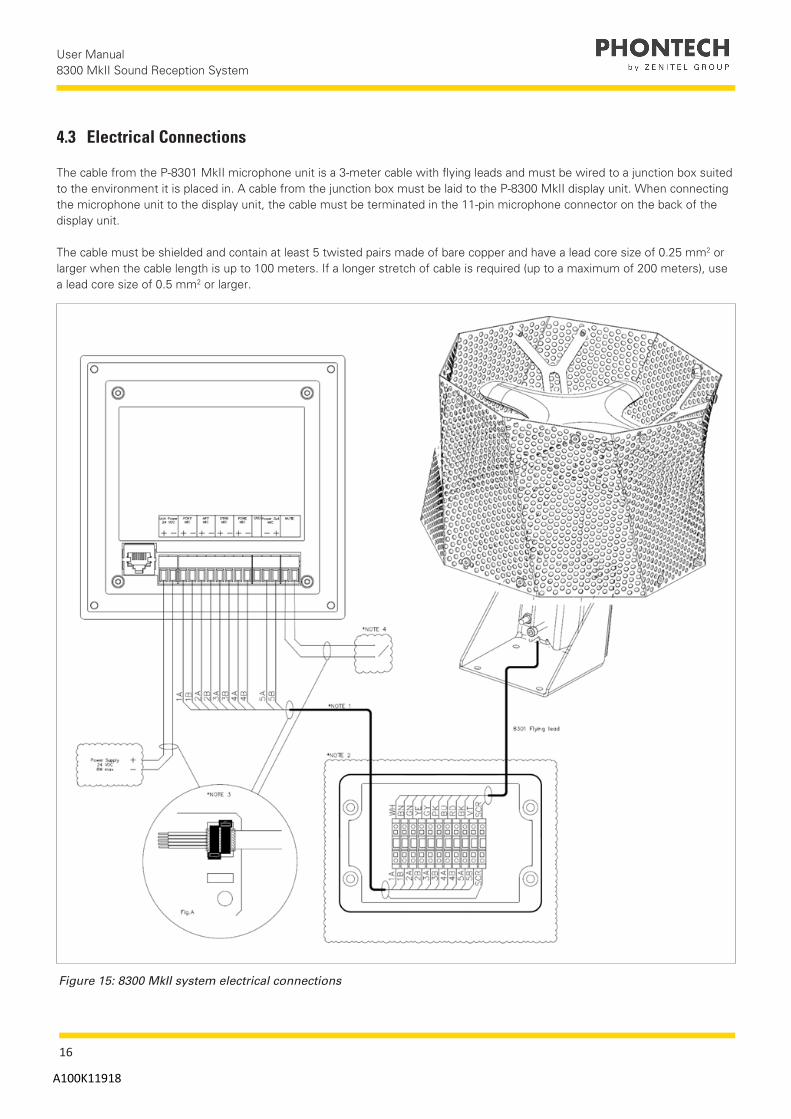
4.3 Electrical Connections
The cable from the P-8301 MkII microphone unit is a 3-meter cable with flying leads and must be wired to a junction box suited to the environment it is placed in. A cable from the junction box must be laid to the P-8300 MkII display unit. When connecting the microphone unit to the display unit, the cable must be terminated in the 11-pin microphone connector on the back of the display unit.
The cable must be shielded and contain at least 5 twisted pairs made of bare copper and have a lead core size of 0.25 mm2 or larger when the cable length is up to 100 meters. If a longer stretch of cable is required (up to a maximum of 200 meters), use a lead core size of 0.5 mm2 or larger.
Figure 15: 8300 MkII system electrical connections

17
User Manual 8300 MkII Sound Reception System
A100K11918
Designation Colour Function
WH White Port +
BN Brown Port -
GN Green Aft +
YE Yellow Aft -
GY Grey Strb +
PK Pink Strb -
BU Blue Fore +
RD Red Fore -
BK Black GND
VT Violet Vinn
NOTE:
Clarification of the notes in the above image:
1. Cabling is not supplied by Zenitel. The cable must be shielded with individual pairs and have a minimum 0.25 mm2 core size.2. A junction box is optional and can be supplied by Zenitel3. To comply with EMC requirements, all cable shields must be safely connected to the chassis as shown.4. The mute signal to the P-8300 MkII display unit. A closing contact (normally open) will mute the sound reception system while closed. Generally, this input is used by the ship's foghorn system.
Figure 16: 8300 MkII Ethernet electrical connections
The setup for the master/slave web interface via a computer or connection to an IEC 61161-450 network is as shown above.
NOTE:
The cable must be a minimum of Cat 5 S/UTP quality. Master/Slave can be connected directly together or via a LAN switch.

18
User Manual 8300 MkII Sound Reception System
A100K11918
5 Operating Instructions
5.1 Operational ModesThe P-8300 MkII display unit has four different operational modes. The volume and lighting can be adjusted.To switch between modes, do the following:• Press and hold the control button for 5 seconds.
NOTE:
Continuing to hold the button will advance you into the next mode. The mode will change for every additional 5 seconds.
5.1.1 Normal ModeWhen the display unit is first started, it will start in normal mode. When in this mode, the unit will idle until a horn signal is detected. Detected horns will play on the speaker and indicate the direction of the source of the signal.
The speaker will play the detected horn at a consistent level regardless of the level of the input. This level can be adjusted using the volume control. Differences in the level of the input can be perceived in the clarity of the signal compared to the background noise.
As a reference, the expected level for a whistle with a fundamental frequency of 120Hz, with a level of 143dB(SPL) within 1/3 octave at 1 meter, from 2 nautical miles should be around 65-70 dB(A) at the listening post. Thesecond volume setting (two notches clockwise when muted) will result in a similar level in dB(A) produced by thedisplay.
Within the first 3 seconds of detection, an 80-degree arch will light up in orange while the center of the arch is lit in red. After 3 seconds, only the red light remains active. Multiple indications can be active at once. The indication pointer will remain for a configurable amount of time (7 seconds by default) after the detection is finished. The indication pointer configuration time can be altered within the web interface.
The light behind the control button is off when the unit is in this mode.
Figure 17: Normal mode, idle
19
User Manual 8300 MkII Sound Reception System
A100K11918
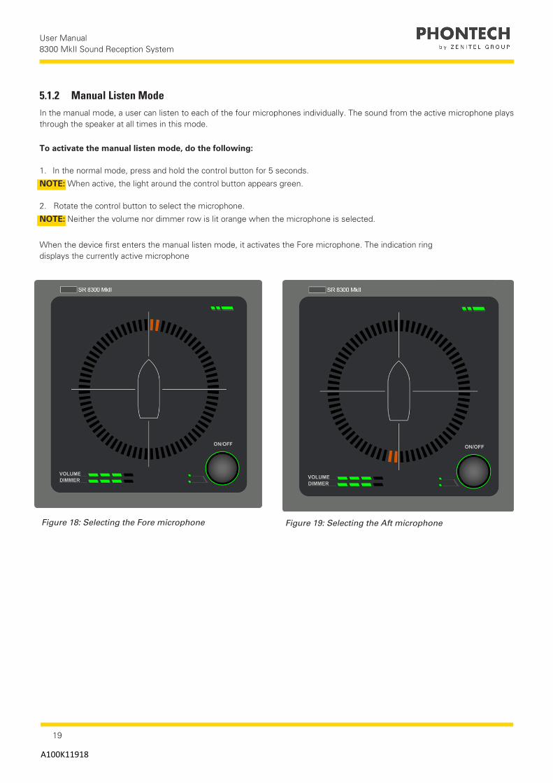
Figure 18: Selecting the Fore microphone Figure 19: Selecting the Aft microphone
5.1.2 Manual Listen ModeIn the manual mode, a user can listen to each of the four microphones individually. The sound from the active microphone plays through the speaker at all times in this mode.
To activate the manual listen mode, do the following:
1. In the normal mode, press and hold the control button for 5 seconds.
NOTE: When active, the light around the control button appears green. 2. Rotate the control button to select the microphone.
NOTE: Neither the volume nor dimmer row is lit orange when the microphone is selected.
When the device first enters the manual listen mode, it activates the Fore microphone. The indication ring displays the currently active microphone
20
User Manual 8300 MkII Sound Reception System
A100K11918
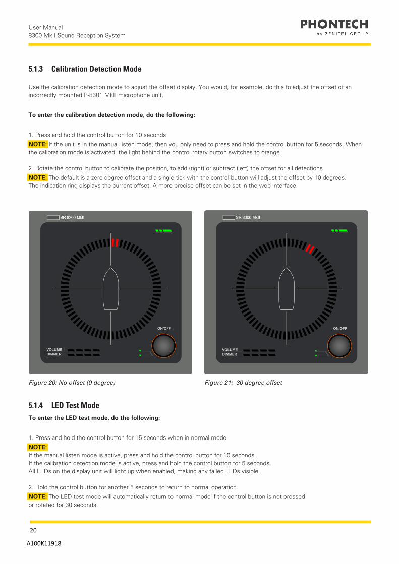
5.1.3 Calibration Detection Mode
Figure 20: No offset (0 degree) Figure 21: 30 degree offset
5.1.4 LED Test ModeTo enter the LED test mode, do the following:
1. Press and hold the control button for 15 seconds when in normal mode
NOTE: If the manual listen mode is active, press and hold the control button for 10 seconds.If the calibration detection mode is active, press and hold the control button for 5 seconds. All LEDs on the display unit will light up when enabled, making any failed LEDs visible.
2. Hold the control button for another 5 seconds to return to normal operation.
NOTE: The LED test mode will automatically return to normal mode if the control button is not pressed or rotated for 30 seconds.
Use the calibration detection mode to adjust the offset display. You would, for example, do this to adjust the offset of an incorrectly mounted P-8301 MkII microphone unit.
To enter the calibration detection mode, do the following:
1. Press and hold the control button for 10 seconds
NOTE: If the unit is in the manual listen mode, then you only need to press and hold the control button for 5 seconds. When the calibration mode is activated, the light behind the control rotary button switches to orange
2. Rotate the control button to calibrate the position, to add (right) or subtract (left) the offset for all detections
NOTE: The default is a zero degree offset and a single tick with the control button will adjust the offset by 10 degrees. The indication ring displays the current offset. A more precise offset can be set in the web interface.

21
User Manual 8300 MkII Sound Reception System
A100K11918
5.2 Network Operations
The 8300 MkII performs multiple network operations according to part 450 of the IEC 61162 standard. This includes inter-device communication and logging.
The transmission groups are mapped to the following multicast addresses and ports:
Transmission Group Address Port Combination
MISC 239.192.0.1:60001
PROP 239.192.0.8:60008
NETA 239.192.0.56:60056
USR1 239.192.0.9:60009
USR2 239.192.0.10:60010
USR3 239.192.0.11:60011
USR4 239.192.0.12:60012
USR5 239.192.0.13:60013
USR6 239.192.0.14:60014
USR7 239.192.0.15:60015
USR8 239.192.0.16:60016
NOTE:
These transmission groups are defined in part 450 of the IEC 61162 standard.
Multiple IEC 61162-450 sentences are sent and received by the P-8300 MkII display unit. Below is a list of the applicable sentences:• SRP Sentence• PJTR sentences (SRS proprietary sentences, HBT sentence and VOL proprietary sentences)• DDC sentences
CAUTION:
For more information or clarification regarding the above sentences, please refer to IEC 61162-450.
22
User Manual 8300 MkII Sound Reception System
A100K11918
5.2.1 PJTR SentenceThe PJTR sentence is a proprietary sentence that is used for communication between the master and slave P-8300 MkII dis-play units.The first parameter of this sentence is the sentence code for our proprietary sentences. The remaining parameters depend on the sentence code that is sent.
The 8300 MkII has the following three proprietary sentences:• Sound Reception Signal (SRS)• Volume (VOL)• Heartbeat (HBT)
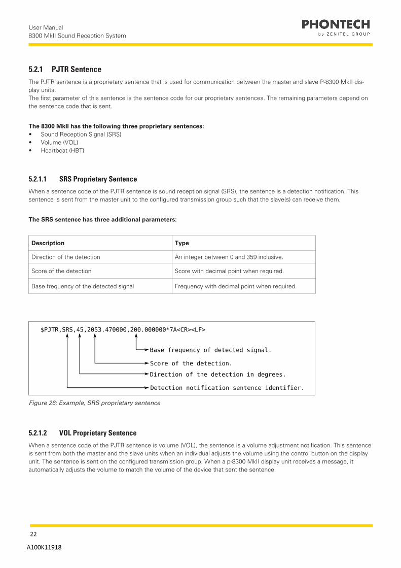
5.2.1.1 SRS Proprietary Sentence
When a sentence code of the PJTR sentence is sound reception signal (SRS), the sentence is a detection notification. This sentence is sent from the master unit to the configured transmission group such that the slave(s) can receive them.
The SRS sentence has three additional parameters:
Description Type
Direction of the detection An integer between 0 and 359 inclusive.
Score of the detection Score with decimal point when required.
Base frequency of the detected signal Frequency with decimal point when required.
Figure 26: Example, SRS proprietary sentence
5.2.1.2 VOL Proprietary Sentence
When a sentence code of the PJTR sentence is volume (VOL), the sentence is a volume adjustment notification. This sentence is sent from both the master and the slave units when an individual adjusts the volume using the control button on the display unit. The sentence is sent on the configured transmission group. When a p-8300 MkII display unit receives a message, it automatically adjusts the volume to match the volume of the device that sent the sentence.

23
User Manual 8300 MkII Sound Reception System
A100K11918
The VOL sentence has one additional parameter:
Description Type
New volume setting An integer between 0 and 99 inclusive.
Figure 27: Example, VOL proprietary sentence
5.2.1.3 HBT Sentence
The P-8300 MkII sends a heartbeat (HBT) sentence once every 60 seconds. This sentence is sent to the MISC transmission group. It is equal to the standard HBT sentence, except that it is sent as a parameter to the PJTR sentence.
NOTE:
Refer to IEC 61162-1 standard for more information regarding heartbeat sentence.
Figure 28: Example, HBT sentence
24
User Manual 8300 MkII Sound Reception System
A100K11918
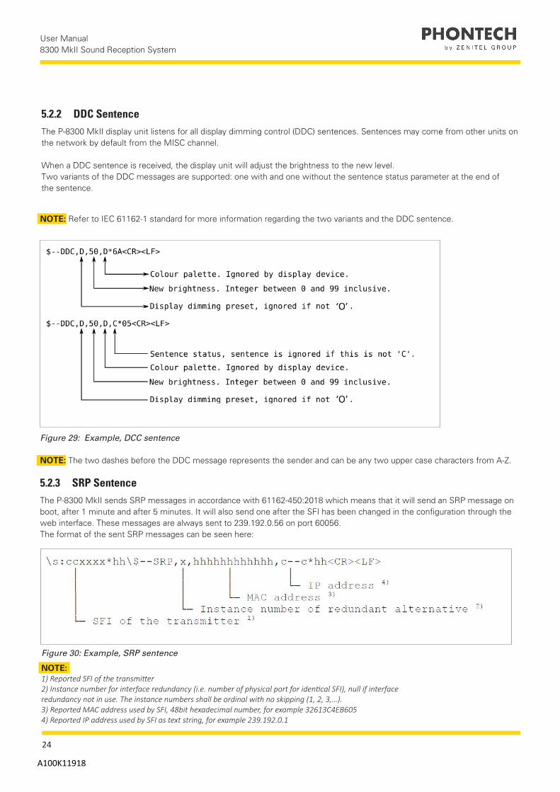
5.2.2 DDC SentenceThe P-8300 MkII display unit listens for all display dimming control (DDC) sentences. Sentences may come from other units on the network by default from the MISC channel.
When a DDC sentence is received, the display unit will adjust the brightness to the new level.Two variants of the DDC messages are supported: one with and one without the sentence status parameter at the end of the sentence.
NOTE: Refer to IEC 61162-1 standard for more information regarding the two variants and the DDC sentence.
NOTE: The two dashes before the DDC message represents the sender and can be any two upper case characters from A-Z.
Figure 29: Example, DCC sentence
5.2.3 SRP SentenceThe P-8300 MkII sends SRP messages in accordance with 61162-450:2018 which means that it will send an SRP message on boot, after 1 minute and after 5 minutes. It will also send one after the SFI has been changed in the configuration through the web interface. These messages are always sent to 239.192.0.56 on port 60056.The format of the sent SRP messages can be seen here:
Figure 30: Example, SRP sentence
NOTE:1) Reported SFI of the transmitter2) Instance number for interface redundancy (i.e. number of physical port for identical SFI), null if interfaceredundancy not in use. The instance numbers shall be ordinal with no skipping (1, 2, 3,…).3) Reported MAC address used by SFI, 48bit hexadecimal number, for example 32613C4EB6054) Reported IP address used by SFI as text string, for example 239.192.0.1

25
User Manual 8300 MkII Sound Reception System
A100K11918
Description Amount
Maximum received per second, intended for target. 50/sec
Maximum received per second, not intended for target- 2000/sec
Maximum received per second, not intended for target at 50% of the maximum load.
1000/sec
5.3 Syslog Messages
When syslog network logging is enabled, syslog messages are sent to the network address specified in the web interface. Refer to the network settings for more information.
The following table lists messages that are sent when there is a problem with the unit.
Message ID Level Message Text Additional Information
SURV_AUDIO_FAILURE Warning Surveillance failed for audio channels: <Mask>
<Mask> is replaced with a bitmask in hex of the channels that have failed audio surveillance.
Available channels: • 0x1 Fore • 0x2 Aft • 0x4 Starboard • 0x8 Port
For example, 0xC indicates a failure of port and starboard microphones.
SURV_LED_FAIL WarningBad health state of LED <LED id>
<LED id> is replaced with the ID of the LED that failed.
SURV_WDOG_NOT_ FEEDING Critical Not feeding watchdog because all required tests have not been passed: <Mask>
Message informs that the unit will restart due to a failing watchdog test. <Mask> is replaced with a bitmask in hex that identifies the failing test.
Tests include:
• 0x1 Audio surveillance test • 0x2 DSP surveillance test • 0x4 Display response surveillance
test
5.2.4 Maximum Data RatesThese are the maximum data rates as required by IEC 61162-450, section 4.3.2.

26
User Manual 8300 MkII Sound Reception System
A100K11918
5.4 Audio Packet Stream
A proprietary audio packet stream is sent together with all other network traffic.
This stream contains the audio data from a detected foghorn signal. The master unit sends the data to the multicast group at 239.192.0.65 on port 5004 and 5005. This audio packet stream is a RTP stream with RTP data on port 5004 and RTCP data on port 5005. The audio is sent as a single channel 24-bit signed PCM at a 24-kHz sampling rate. The RTP stream uses a packet size of 20 ms.
An audio stream is only sent when a foghorn is detected and stops when the detection ends.
The maximum bandwidth used by this stream is 96 kB/s, with approximately 50 packets per second.
5.3.1 Syslog levels
• Emergency – System malfunction that causes the system to halt• Alert – Not in use• Critical – System malfunction that might cause the system to fail• Error – System malfunction that might cause erratic operation• Warning – System malfunction that might cause incorrect operation• Notice – No logging (default level)• Info – Information messages• Debug – Debugging messages (for service purposes only)

27
User Manual 8300 MkII Sound Reception System
A100K11918
5.5 Error IndicatorWhen an error is detected, the status LED on the P-8300 MkII display unit lights up orange.
Figure 22: Indicating an error is detected
NOTE: For more information regarding potential failures or issues, refer to the section on Troubleshooting.
NOTE: You can adjust the display timing (in seconds) in the web interface.
5.6 Detecting a Sound SignalWhen the P-8300 MkII detects a sound signal and determines the direction of the signal, the direction will appearon the display unit.
Figure 23: Sound signal, as it is detected
After 3 seconds, the orange LEDs disappear and the red LEDs remain. The red LED indicators remains by default for 7 seconds or the configured length of time.
Figure 24: Sound signal, 3 seconds after detection

28
User Manual 8300 MkII Sound Reception System
A100K11918
kII is able to detect multiple sound signals simultaneously.
Figure 25: Detecting multiple sound signals, 0˚ and 310˚
Figure 26: Detecting multiple sound signals 3 seconds after detection
29
User Manual 8300 MkII Sound Reception System
A100K11918
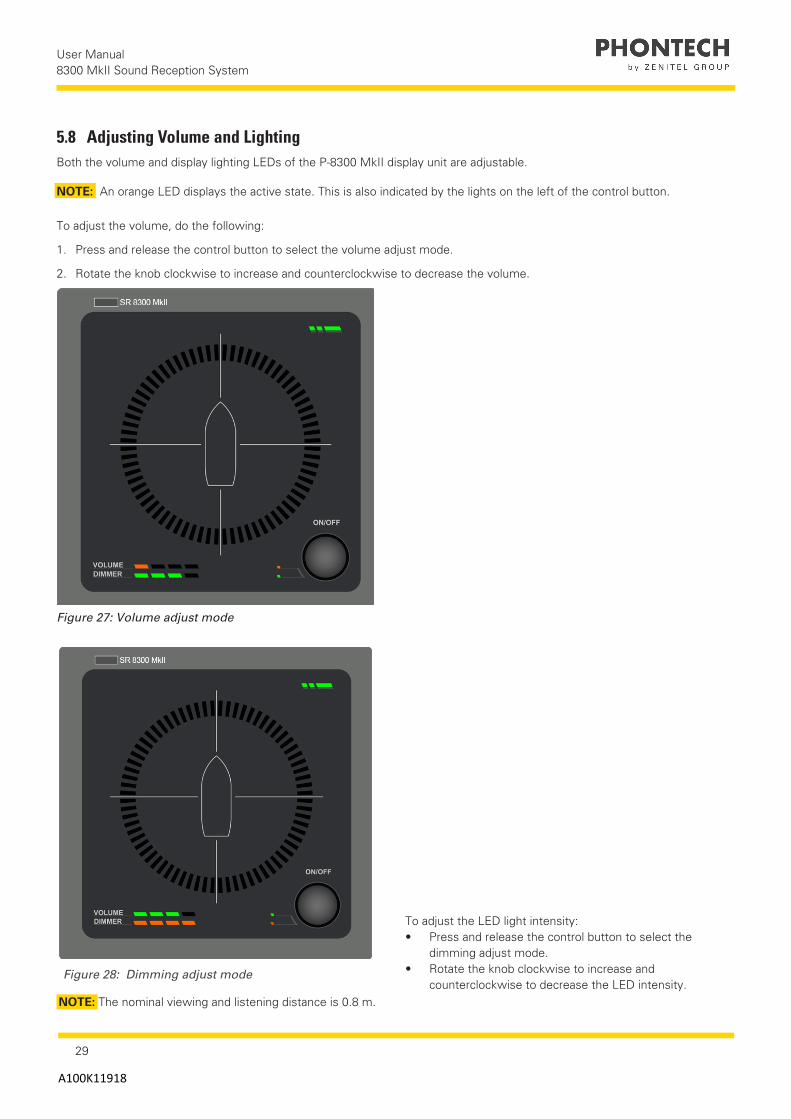
5.8 Adjusting Volume and LightingBoth the volume and display lighting LEDs of the P-8300 MkII display unit are adjustable.
NOTE: An orange LED displays the active state. This is also indicated by the lights on the left of the control button.
To adjust the volume, do the following:
1. Press and release the control button to select the volume adjust mode.
2. Rotate the knob clockwise to increase and counterclockwise to decrease the volume.
To adjust the LED light intensity:• Press and release the control button to select the
dimming adjust mode.• Rotate the knob clockwise to increase and
counterclockwise to decrease the LED intensity.
Figure 27: Volume adjust mode
NOTE: The nominal viewing and listening distance is 0.8 m.
Figure 28: Dimming adjust mode
30
User Manual 8300 MkII Sound Reception System
A100K11918
NOTE:
Some changes require a reboot of the unit. If this is the case, the web interface will display a message indicating that a reboot is necessary. This is done in Additional options and is explained under Maintenance.
IMPORTANT:
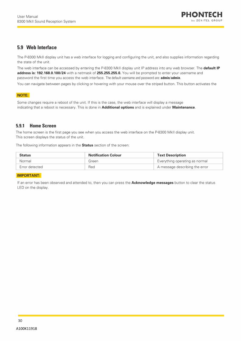
If an error has been observed and attended to, then you can press the Acknowledge messages button to clear the status LED on the display.
5.9 Web Interface
The P-8300 MkII display unit has a web interface for logging and configuring the unit, and also supplies information regarding the state of the unit.
The web interface can be accessed by entering the P-8300 MkII display unit IP address into any web browser. The default IP address is: 192.168.0.100/24 with a netmask of 255.255.255.0. You will be prompted to enter your username and password the first time you access the web interface. The default username and password are: admin/admin.
You can navigate between pages by clicking or hovering with your mouse over the striped button. This button activates the
5.9.1 Home ScreenThe home screen is the first page you see when you access the web interface on the P-8300 MkII display unit. This screen displays the status of the unit.
The following information appears in the Status section of the screen:
Status Notification Colour Text Description
Normal Green Everything operating as normal
Error detected Red A message describing the error

31
User Manual 8300 MkII Sound Reception System
A100K11918
Figure 29: Home screen, status OK - acknowledge messages
Figure 30: Home screen, status Failed - Acknowledge messages

32
User Manual 8300 MkII Sound Reception System
A100K11918
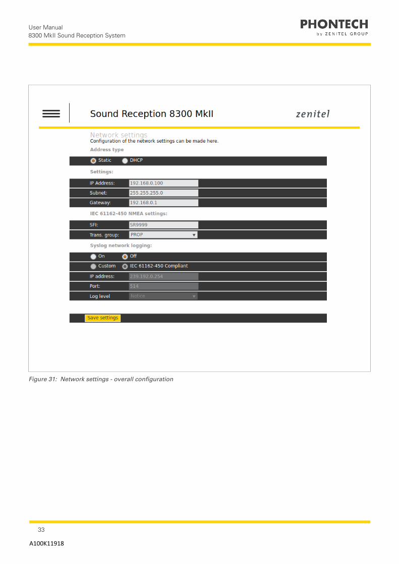
5.9.2 Network SettingsYou can configure the following network settings:
Configurable network settings Description
Network address of the unit (2 options)
1. Static - this option allows you to configure any static network address along with the applicable netmask and gateway.2. DHCP - this option will request the DHCP server for an address either when you start the unit or when a network cable is plugged in.
IEC 61162-450 settings Configure the transmission group used for sending and receiving messages by selecting from the PROP or USR1-USR8 groups.
Syslog settings You can enable the device logging over network through the syslog protocol. By enabling the syslog network logging the Phontech 8300 MkII display unit will send information and error messages over the Ethernet network. Syslog messages can either be sent to the IEC 61162-450 compliant address (239.192.0.254:514) or a user can configure a custom server address by changing the IP address and port fields in the syslog section. To change the messages that are logged, ensure you change the log level setting in the same section, the options range from Debug to Emergency priority. When this is set, all messages at the selected level or higher will be sent to the syslog server.
NOTE:
The default network address is an IEC 61162-450 compliant address of 192.186.0.100
IMPORTANT:
Prior to using the P-8300 MkII display unit on an IEC 61162-450 network to send sentences to other units, a valid SFI address must be configured. The configuration value for the address must start with SR and be followed by 4 digits, for example SR0001. In a system consisting of more than one SR P-8300, the different units must have different SFI addresses.
To configure the network settings:
1. Select the address type.2. Enter the applicable settings (Subnet/Gateway).3. Enter the applicable IEC 61162-450 NMEA settings 4. Select the Syslog network options (See chapter 5.3.1.)5. Click the Save settings button.
33
User Manual 8300 MkII Sound Reception System
A100K11918
Figure 31: Network settings - overall configuration

34
User Manual 8300 MkII Sound Reception System
A100K11918
5.9.3 Audio SettingsThe audio settings of the P-8300 MkII display unit allows a user to adjust the signal-to-noise ratio required prior to a foghorn being detected. The default value is 2.25, calibrated to handle a foghorn where the bulk of the energy lies between 700-2100 Hz from 0.5 nautical miles when a horn creates a 111 dB SPL sound level.
The signal-to-noise ratio configuration ranges from 2 to 6. The higher the values the stricter the P-8300 MkII display unit will be in detecting foghorns. Lower values will detect more foghorns, but are more susceptible to false detections.
To configure the signal-to-noise ratio:
1. Use the slider or manually type in a value.2. Click the Save settings button.
Figure 32: Audio settings - signal-to-noise ratio
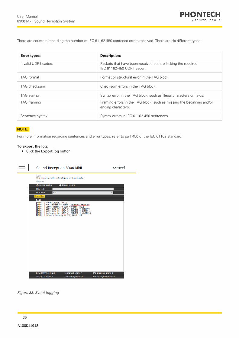
5.9.4 System LogThe P-8300 MkII display unit has a logging feature that enables logging at several levels. The system log page displays a real-time log of the system, in addition to previously generated messages.
To view logs:
• Click the Enable logging button.
NOTE:
Log messages will appear in the window below.As long as logging is enabled, messages will continue to come as they are generated on the unit.
To search or filter a log:
• Use the Filter text or Filter level settings.
NOTE:
This displays only log lines that contain a phrase or are as important as the given log level.
35
User Manual 8300 MkII Sound Reception System
A100K11918
There are counters recording the number of IEC 61162-450 sentence errors received. There are six different types:
Error types: Description:
Invalid UDP headers Packets that have been received but are lacking the required IEC 61162-450 UDP header.
TAG format Format or structural error in the TAG block
TAG checksum Checksum errors in the TAG block.
TAG syntax Syntax error in the TAG block, such as illegal characters or fields.
TAG framing Framing errors in the TAG block, such as missing the beginning and/or ending characters.
Sentence syntax Syntax errors in IEC 61162-450 sentences.
Figure 33: Event logging
NOTE:
For more information regarding sentences and error types, refer to part 450 of the IEC 61162 standard.
To export the log:• Click the Export log button

36
User Manual 8300 MkII Sound Reception System
A100K11918
5.9.5 Additional OptionsThe Additional options page contains configuration options that do not fall under any of the other categories.
To adjust any of these options:
1. Select the applicable option.2. Enter the applicable information.3. Click the Save settings button.
Options: Description:
Detection direction: ForeThis is the default setting. If Fore is selected, horns detected to the fore of the microphone unit will be displayed at the fore of the display unit.
Detection direction: AftIf Aft is selected, all horns detected will be offset by 180˚ in the display unit. Horns detected to the fore of the microphone unit, will be displayed at the aft of the display unit.
MasterThis is the default setting. The master unit must be connected to the microphone unit. The master unit will transmit all detected signals to any slave units over Ethernet.
SlaveThe slave unit can not be connected to the microphone unit, but will receive detections and sound from the master unit over Ethernet. There may be multiple slave units in an installation.
Alignment offsetUse this setting to add an offset to all detections in case the microphone unit has not been mounted accurately in the fore direction.
Pointer holdUse this setting to adjust the length of time a detection is displayed after the detection has ended. The default value is 7 seconds.
IMPORTANT:
When working with a master or slave setup, all units must be:• Connected to the same network.• Configured with different IP addresses.
• Use the same transmission group.
NOTE:
You can view more information about the options by clicking on the (?) question mark buttons next to the
individual options.
The Additional options page also offers the possibility to do the following maintenance:• Firmware updates• Restore the unit to the factory defaults• Reboot the system
To complete any of the additional maintenance options:• To complete a Firmware update, click Update firmware• To restore the factory defaults, click Factory reset• To reboot the system, click Reboot

37
User Manual 8300 MkII Sound Reception System
A100K11918
Figure 34: Additional options, including maintenance (update firmware, reset and reboot)

38
User Manual 8300 MkII Sound Reception System
A100K11918
6 TestingTesting should be done as required.
6.1 Calibration and TestingTesting of the operational functionality of the 8300 MkII is done using a foghorn.
NOTE:
The 8300 MkII automatically and continuously tests both the display and microphone unit.In the event of an error, the error will be displayed by the LEDs in the web interface or in the syslog server (if configured).
Foghorn activity should be in 3-second bursts with at least 10 seconds between each burst.
NOTE:
If the microphone unit is not correctly mounted, the display unit can compensate for this by adding an offset to the detections.Check the calibration mode or additional options.
7 MaintenanceAll maintenance options for the 8300 MkII are completed in the Additional options page of the web interface. The maintenance options are as follows:• Upgrade or view the current firmware version.• Perform a factory reset.
To perform a firmware upgrade:
1. Click the Update firmware button.2. Select the firmware upgrade package in the dialog box
NOTE:
When the firmware upgrade is complete, the unit will automatically restart
To perform a factory reset:
1. Click the Factory reset button.2. Click Yes in the dialog box.
NOTE:
All configuration options will be reset to the factory default, including the network IP address setting. The default network IP address (192.168.0.100) must be entered manually in a web browser to regain access to the web interface.If the original default address was not changed, the web interface will refresh automatically. When the reset is complete, the unit will automatically restart.
To perform a reboot:
• Click the Reboot button.
39
User Manual 8300 MkII Sound Reception System
A100K11918
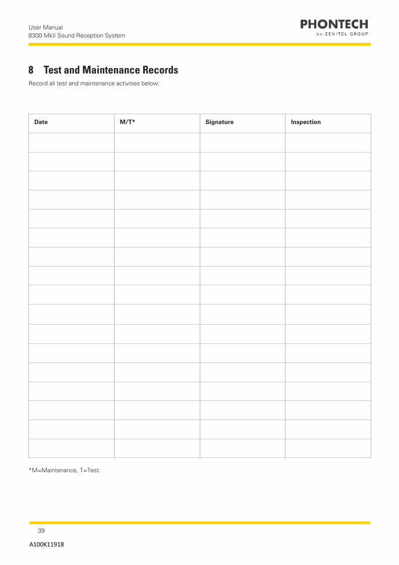
Date M/T* Signature Inspection
*M=Maintenance, T=Test.
8 Test and Maintenance RecordsRecord all test and maintenance activities below:

40
User Manual 8300 MkII Sound Reception System
A100K11918
9 TroubleshootingIf the P-8300 MkII display unit detects a problem, the front status LED will switch from green to orange.
To get an indication of what may be wrong, do one of the following:• Check the syslog server if syslog network logging is enabled• Check the web interface of the unit
Below are tips for solving the following potential failures or issues:• Microphone surveillance failure• LED surveillance failure• Foghorn detection failure• Display unit boot failure
1. Start the LED test mode
■NOTE: Do this when only 1 microphone has failed.
After checking the cabling, restart or acknowledge the error message in the web interface.
9.1 Microphone Surveillance FailureIf the signal coming from one or more of the microphones on the P-8301 MkII microphone unit is malfunctioning, do the following:
1. Check the cabling
NOTE:
The power leads should be connected to the display unit, on the left side of the Mute connection. A description of all the connectors is displayed on the back of the unit.If the web interface indicates that all microphones are down, then the problem might lie within the power cable going to the microphone unit.
2. Check the individual microphone cabling
NOTE:
Do this when only one microphone has failed. After checking the cabling, restart or acknowledge the error message in the web interface.
3. Inspect the unit for physical obstruction of the failing microphone.
NOTE:
If you do not find any visible obstruction on the microphone, the unit should be consider damaged. In this case, contact Zenitel for support.Internal parts of the microphone unit are not serviceable.
9.2 LED Surveillance FailureIf a LED failure is indicated, do the following:
• Start the LED test mode
NOTE:
This should indicate which LED is failing.
If any of the red indicator LEDs have stopped working, a foghorn detection might not be visible to the user; in this event contact Zenitel for support.Refer to the additional information under the LED test mode.
41
User Manual 8300 MkII Sound Reception System
A100K11918
9.3 Foghorn Detection FailureIf the unit fails to detect a foghorn, do the following:
1. Check to see if there are any microphone surveillance failure messages in the web interface.
NOTE: Refer to the additional information under Microphone Surveillance Failure.
2. Adjust the signal to noise ratio setting in the web interface.
NOTE: Refer to the additional information under Audio Settings.
3. Do a factory reset.
NOTE: Refer to the additional information under Maintenance.
9.4 Display Unit Boot FailureIf the P-8300 MkII display unit fails to start when power is connected, do the following:• Press and hold the reset button at the back of the display unit for 10 seconds.
NOTE: Power must be connected to the unit to recover the firmware.
CAUTION: If the firmware starts the unit properly, do a firmware upgrade to ensure the primary firmware is not corrupt.After upgrade, the unit will restart with the primary firmware loaded. The recovery firmware can always be accessed by performing this step again.
Refer to the additional information under Additional Options.
WarrantyWhen purchasing a new 8300 MkII, the warranty period is valid for 2 years from the date the product is shipped from Zenitel. If you have a 8300 MkII and are unclear about your warranty period contact Zenitel.
All Zenitel products are warranted against factory defects in materials and/or workmanship during the warranty period, unless otherwise stated in writing. Please refer to the terms and conditions of your sales agreement for additional information.
During this warranty period Zenitel will repair or when necessary replace a product to a sum that does not exceed the net invoice value of the defective equipment.
Zenitel reserves the right to decide whether a defective product falls within the terms and conditions of the warranty.
The warranty is only valid as long as the equipment has been handled properly in accordance with Zenitel instructions, manuals and specifications, including required service and maintenance, in particular service or maintenance that must be carried out by an authorized Zenitel agent or distributor. A warranty will be considered void in the instance that any equipment has been accidentally damaged, misused, tampered with and/or is dysfunctional as a result of services or modifications performed by an unauthorized person or in an unauthorized facility.
IMPORTANT:
Zenitel is not liable for consequential or special damages and cannot be held responsible for any damages caused due to incorrect usage of the equipment, breach of procedures, or the failure of any specific component or other part of the equipment.
For product support contact: [email protected]
42
User Manual 8300 MkII Sound Reception System
A100K11918
Warranty ClaimsWarranty claims can be submitted during the warranty period, all claims will be appropriately handled according to the warranty agreement specified for this product and in accordance with the terms and conditions of your sales agreement.
Prior to returning your product for product claims you must submit at warranty claim in writing to [email protected].
NOTE:
Zenitel does not accept any responsibility for the dismantling or reassembling of a 8300 MkII that occurs externally from a Zenitel authorized facility and/or is handled by someone other than an authorized, trained and certified person.
ServiceAll services such as installation, maintenance or replacement must by done by an authorized Zenitel service agent.
CAUTION:
Improper maintenance may destroy the functionality and/or performance of this product.
Spare PartsKeep the original packaging. If the 8300 MkII needs to be shipped for servicing, it is required to be shipped within the same packaging as when the product was first received.
Part Number Part Name
4000019415 P-8300 MkII display unit
4000019416 P-8301 MkII microphone unit
4000019634 Junction Box (optional)
IMPORTANT:
Ensure that all spare parts being fitted to the 8300 MkII are original spare parts manufactured or approved by Zenitel.Any use of counterfeit spare parts will deviate from the product type approval certificates.
Recycling & DisposalThe 8300 MkII is not to be disposed as normal waste and must be handled in accordance with the applicable waste disposal regulations in the country where the equipment is used.
Support/ContactZenitel Customer [email protected] Phone +47 40002700

www.zenitel.com
Zenitel Norway ASBromsveien 17 3183 HortenP.O. Box 1068 Bekkajordet3194 Horten Norway
Tel. +47 40 00 27 00 Fax. +47 33 03 16 61
Zenitel and its subsidiaries assume no responsibility for any errors that may appear in this publication, or for damages arising from the information therein. Phontech products are developed and marketed by Zenitel. The company’s Quality Assurance System is certified to meet the requirements in NS-EN ISO 9001. Zenitel reserves the right to modify designs and alter specifications without notice. ZENITEL PROPRIETARY. This document and its supplementing elements, contain Zenitel or third party information which is proprietary and confidential. Any disclosure, copying, distribution or use is prohibited, if not otherwise explicitly agreed in writing with Zenitel. Any authorized reproduction, in part or in whole, must include this legend: Zenitel – All Rights Reserved
Document Number: A100K11918