Embed Size (px)
Citation preview
A9500 user manual Page 1 of 37
A9500 USER MANUAL

A9500 user manual Page 2 of 37
IMPORTANT NOTICE
CPOYRIGHT NOTICE Copyright: LongSung Technology (Shanghai) Co., Ltd. All rights reserved. TRADEMARKS LongSung Technology (Shanghai) Co., Ltd’s products are exclusively owned by LongSung Technology (Shanghai) Co., Ltd. References to other companies and their products use trademarks owned by the respective companies and are for reference purpose only. CONFIDENTIALITY
The information contained here (including any attachments) is confidential. The recipient here acknowledges the confidentiality of this document, and except for the specific purpose, this document shall not be disclosed to any third party. WARRANTY DISCLAIMER LongSung Technology (Shanghai) Co., Ltd makes no representations or warranties, either express or implied, by or with respect to anything in this document, and shall not be liable for any implied warranties of merchantability or fitness for a particular purpose or for any indirect, special or consequential damages. NO GUARANTEE Our company will not take any responsibility for any damage caused by the customer’s abnormal operation. Please refer to specification and designing reference guide. Our company have right to modify the document according to technical requirement with no announcement to the customer.
A9500 user manual Page 3 of 37
FCC Caution:
(1)Exposure to Radio Frequency Radiation. This equipment must be installed and operated in accordance with provided instructions and the antenna(s) used for this transmitter must be installed to provide a separation distance of at least 20cm from all persons and must not be collocated or operating in conjunction with any other antenna or transmitter. End-users and installers must be provided with antenna installation instructions and transmitter operating conditions for satisfying RF exposure compliance. (2) Any changes or modifications not expressly approved by the grantee of this device could void the user’s authority to operate the equipment. (3) This Transmitter must not be co-located or operating in conjunction with any other antenna or transmitter. (4) Changes or modifications to this unit not expressly approved by the party responsible for compliance could void the user authority to operate the equipment. (5) the modules FCC ID is not visible when installed in the host, or (6) if the host is marketed so that end users do not have straight forward commonly used methods for access to remove the module so that the FCC ID of the module is visible; then an additional permanent label referring to the enclosed module: Contains Transmitter Module FCC ID: XHZA9500 or Contains FCC ID: XHZA9500 must be used.
This device complies with Part 15 of the FCC Rules.
Operation is subject to the condition that this device does not cause harmful interference.
A9500 user manual Page 4 of 37
Content
1. Overview .................................................................................................................................................... 8
1.1. Purpose of the Document ................................................................................................................ 8
1.2. Summary ......................................................................................................................................... 8
1.3. Related Documents ......................................................................................................................... 8
1.4. Document History ........................................................................................................................... 9
1.5. Abbreviations .................................................................................................................................. 9
2.Introduction ............................................................................................................................................ 11
2.1. Required Equipment ..................................................................................................................... 11
3. Setup and Install....................................................................................................................................... 12
3.1. Hardware environment setup ........................................................................................................ 12
3.1.1. How to insert SIM/USIM card ........................................................................................... 12
3.1.2. How to connect module ..................................................................................................... 13
3.1.3. How to connect antenna ..................................................................................................... 14
3.1.4. How to connect USB port .................................................................................................. 15
3.1.5. How to connect the UART port ......................................................................................... 16
3.1.6. How to power on ................................................................................................................ 17
3.1.7. How to power off ............................................................................................................... 18
3.2 Software environment setup .......................................................................................................... 18
3.2.1. How to install the drivers ................................................................................................... 18
3.2.2. How to update the firmware............................................................................................... 23
4. Test and Debug ........................................................................................................................................ 26
4.1. How to use USB communication .................................................................................................. 26
4.2. How to do the data connection ...................................................................................................... 29
4.3. How to connect the external power supply ................................................................................... 32
4.4. How to use UART communication ............................................................................................... 33
4.5. How to reset the module ............................................................................................................... 37
4.6. How to enter into the flight mode ................................................................................................. 37

A9500 user manual Page 5 of 37
Table
Table 1:Document history ................................................................................................................... 9
Table 2:Abbreviations and description ................................................................................................ 9
Table 3:EVB Kit list .......................................................................................................................... 11
A9500 user manual Page 6 of 37
Diagram
Figure 1:EVB front view................................................................................................................... 12
Figure 2:SIM card placement view ................................................................................................... 13
Figure 3:Mini-PCIe connector location view .................................................................................... 14
Figure 4:Module insert EVB view .................................................................................................... 14
Figure 5:Front view of module ......................................................................................................... 15
Figure 6:Antenna transit cable connection view ............................................................................... 15
Figure 7:USB port connection view .................................................................................................. 16
Figure 8:UART port connection view ............................................................................................... 17
Figure 9:Power button position view ................................................................................................ 18
Figure 10:Find new hardware ........................................................................................................... 19
Figure 11:Update the drivers ............................................................................................................. 19
Figure 12:Install the drivers manually .............................................................................................. 20
Figure 13:Select the driver path ........................................................................................................ 20
Figure 14:Select the drivers .............................................................................................................. 21
Figure 15:Driver is installing ............................................................................................................ 21
Figure 16:Driver install successfully ................................................................................................ 22
Figure 17:A9500 ports display in the device manager ...................................................................... 23
Figure 18:One key upgrade connection method ............................................................................... 23
Figure 19:A9500 module display in the device manager .................................................................. 24
Figure 20:An example of firmware file ............................................................................................ 24
Figure 21:Firmware upgrading start window\ ................................................................................... 24
Figure 22:Firmware is upgrading ...................................................................................................... 25
Figure 23:Finished on the firmware upgrading ................................................................................. 25
Figure 24:A9500 LongSung USB Modem[AT] port......................................................................... 26
Figure 25:Check the port number ..................................................................................................... 27
Figure 26:New a hyper terminal ....................................................................................................... 27
Figure 27:Select the port number ...................................................................................................... 28
Figure 28:Configure the hyper terminal ............................................................................................ 28
Figure 29:Use hyper terminal to send AT commands ....................................................................... 29
Figure 30:Configure a new network connection ............................................................................... 30
Figure 31:Select modem ................................................................................................................... 30
Figure 32:Input the dial number ........................................................................................................ 31
Figure 33:Network connecting.......................................................................................................... 32
Figure 34:Network connection successfully ..................................................................................... 32
Figure 35:External power supply connection view ........................................................................... 33
Figure 36:UART jumper cap configure ............................................................................................ 34
Figure 37:UART data cable connection view ................................................................................... 34
Figure 38:Check the UART port ....................................................................................................... 34
Figure 39:New a hyper termial ......................................................................................................... 35
Figure 40:Configure the hyper terminal - 1 ...................................................................................... 35
Figure 41:Configure the hyper terminal - 2 ...................................................................................... 36
A9500 user manual Page 7 of 37
Figure 42:Send AT commands in the hyper terminal ........................................................................ 36
Figure 43:Reset key position view .................................................................................................... 37
A9500 user manual Page 8 of 37
1. Overview
The EVB is designed to test the functionality and performance of the LongSung modules. It provides user to evaluate the related development of the module.
1.1. Purpose of the Document
The document takes A9500 as an example to explain the basic functions and main features of EVB, the setup of hardware and software environments and the implementation method of normal business on EVB.
1.2. Summary
The document is divided into the following sections: Chapter 1, mainly introduces the purpose of document, related information, revised records,
interpretation of abbreviations; Chapter 2, describes the development environment of EVB equipment list; Chapter 3, a detailed description of the EVB hardware and software setup environment; Chapter 4, a detailed description of EVB normal business implementation method.
1.3. Related Documents
A9500_SPEC A9500_ATC A9500_Hardware_User_Guide A9500_Reference_Circuit A9500_Application_Guide
A9500 user manual Page 9 of 37
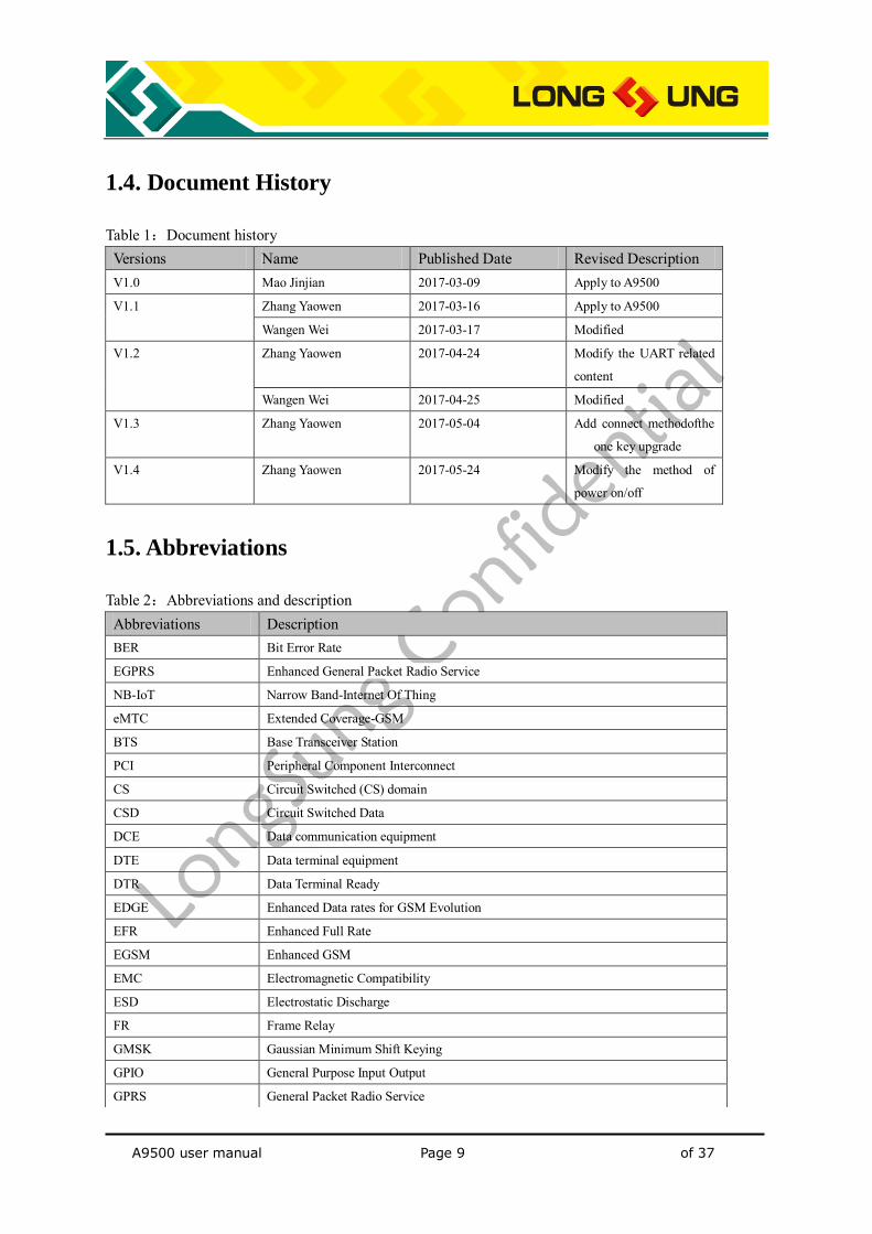
1.4. Document History
Table 1:Document history Versions Name Published Date Revised Description V1.0 Mao Jinjian 2017-03-09 Apply to A9500
V1.1 Zhang Yaowen 2017-03-16 Apply to A9500
Wangen Wei 2017-03-17 Modified
V1.2 Zhang Yaowen 2017-04-24 Modify the UART related
content
Wangen Wei 2017-04-25 Modified
V1.3 Zhang Yaowen 2017-05-04 Add connect methodofthe
one key upgrade
V1.4 Zhang Yaowen 2017-05-24 Modify the method of
power on/off
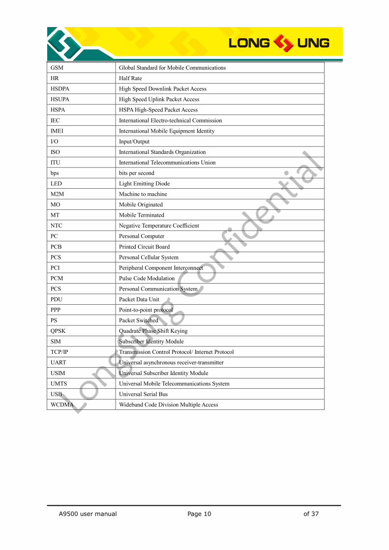
1.5. Abbreviations
Table 2:Abbreviations and description Abbreviations Description BER Bit Error Rate
EGPRS Enhanced General Packet Radio Service
NB-IoT Narrow Band-Internet Of Thing
eMTC Extended Coverage-GSM
BTS Base Transceiver Station
PCI Peripheral Component Interconnect
CS Circuit Switched (CS) domain
CSD Circuit Switched Data
DCE Data communication equipment
DTE Data terminal equipment
DTR Data Terminal Ready
EDGE Enhanced Data rates for GSM Evolution
EFR Enhanced Full Rate
EGSM Enhanced GSM
EMC Electromagnetic Compatibility
ESD Electrostatic Discharge
FR Frame Relay
GMSK Gaussian Minimum Shift Keying
GPIO General Purpose Input Output
GPRS General Packet Radio Service
A9500 user manual Page 10 of 37
GSM Global Standard for Mobile Communications
HR Half Rate
HSDPA High Speed Downlink Packet Access
HSUPA High Speed Uplink Packet Access
HSPA HSPA High-Speed Packet Access
IEC International Electro-technical Commission
IMEI International Mobile Equipment Identity
I/O Input/Output
ISO International Standards Organization
ITU International Telecommunications Union
bps bits per second
LED Light Emitting Diode
M2M Machine to machine
MO Mobile Originated
MT Mobile Terminated
NTC Negative Temperature Coefficient
PC Personal Computer
PCB Printed Circuit Board
PCS Personal Cellular System
PCI Peripheral Component Interconnect
PCM Pulse Code Modulation
PCS Personal Communication System
PDU Packet Data Unit
PPP Point-to-point protocol
PS Packet Switched
QPSK Quadrate Phase Shift Keying
SIM Subscriber Identity Module
TCP/IP Transmission Control Protocol/ Internet Protocol
UART Universal asynchronous receiver-transmitter
USIM Universal Subscriber Identity Module
UMTS Universal Mobile Telecommunications System
USB Universal Serial Bus
WCDMA Wideband Code Division Multiple Access
A9500 user manual Page 11 of 37
2.Introduction
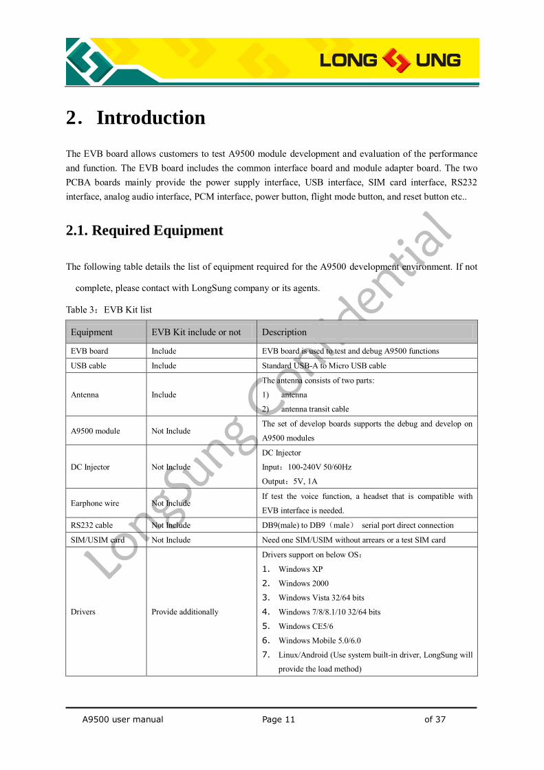
The EVB board allows customers to test A9500 module development and evaluation of the performance and function. The EVB board includes the common interface board and module adapter board. The two PCBA boards mainly provide the power supply interface, USB interface, SIM card interface, RS232 interface, analog audio interface, PCM interface, power button, flight mode button, and reset button etc..
2.1. Required Equipment
The following table details the list of equipment required for the A9500 development environment. If not
complete, please contact with LongSung company or its agents.
Table 3:EVB Kit list
Equipment EVB Kit include or not Description
EVB board Include EVB board is used to test and debug A9500 functions
USB cable Include Standard USB-A to Micro USB cable
Antenna Include
The antenna consists of two parts:
1) antenna
2) antenna transit cable
A9500 module Not Include The set of develop boards supports the debug and develop on
A9500 modules
DC Injector Not Include
DC Injector
Input:100-240V 50/60Hz
Output:5V, 1A
Earphone wire Not Include If test the voice function, a headset that is compatible with
EVB interface is needed.
RS232 cable Not Include DB9(male) to DB9(male) serial port direct connection
SIM/USIM card Not Include Need one SIM/USIM without arrears or a test SIM card
Drivers Provide additionally
Drivers support on below OS:
1. Windows XP
2. Windows 2000
3. Windows Vista 32/64 bits
4. Windows 7/8/8.1/10 32/64 bits
5. Windows CE5/6
6. Windows Mobile 5.0/6.0
7. Linux/Android (Use system built-in driver, LongSung will
provide the load method)
A9500 user manual Page 12 of 37
3. Setup and Install
EVB include the hardware environment setup and software environment setup: 1) Hardware environment setup
How to insert SIM/USIM card; How to connect module; How to connect antenna; How to connect USB cable; How to power on; How to power off.
2) Software environment setup How to install the drivers; How to upgrade the firmware version
3.1. Hardware environment setup
3.1.1. How to insert SIM/USIM card
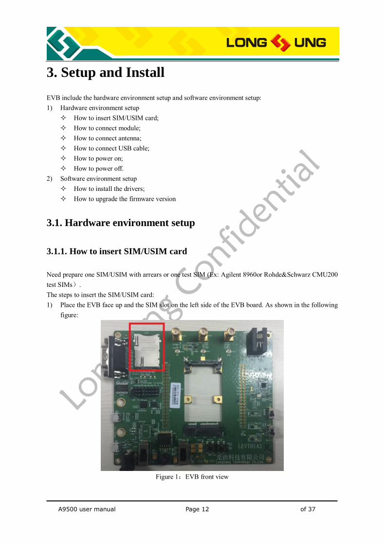
Need prepare one SIM/USIM with arrears or one test SIM (Ex: Agilent 8960or Rohde&Schwarz CMU200 test SIMs). The steps to insert the SIM/USIM card: 1) Place the EVB face up and the SIM slot on the left side of the EVB board. As shown in the following
figure:
Figure 1:EVB front view
A9500 user manual Page 13 of 37
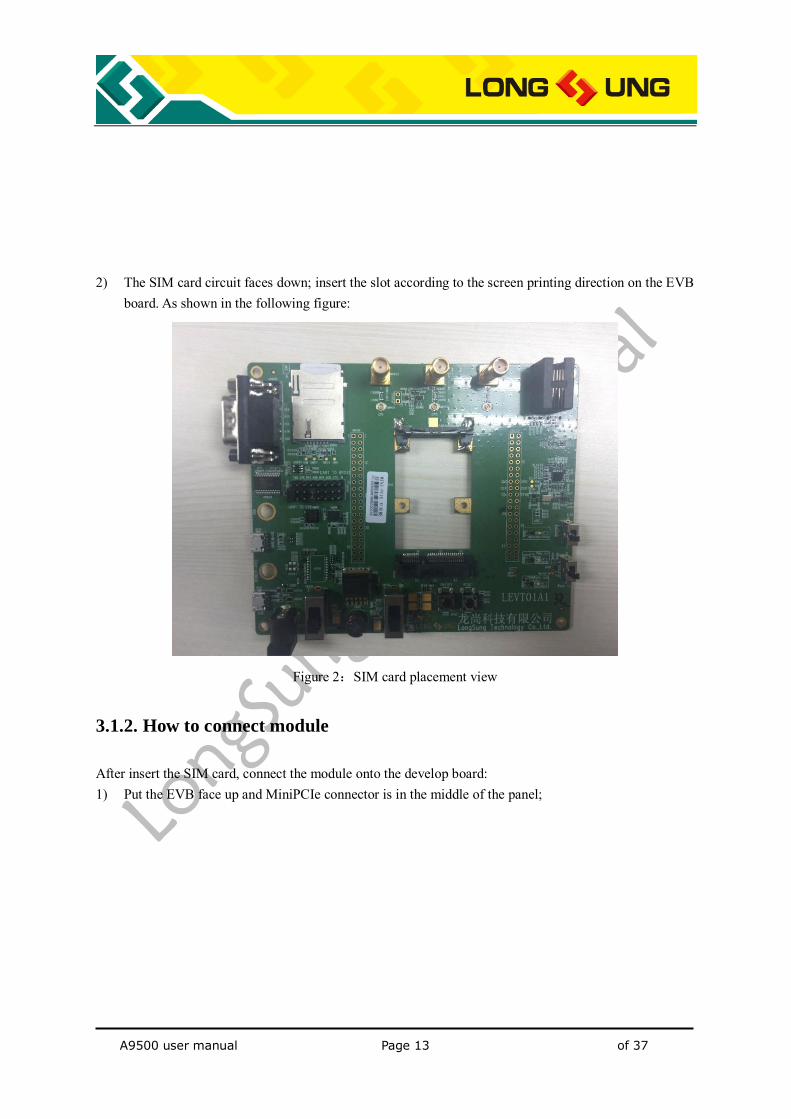
2) The SIM card circuit faces down; insert the slot according to the screen printing direction on the EVB
board. As shown in the following figure:
Figure 2:SIM card placement view
3.1.2. How to connect module
After insert the SIM card, connect the module onto the develop board: 1) Put the EVB face up and MiniPCIe connector is in the middle of the panel;
A9500 user manual Page 14 of 37
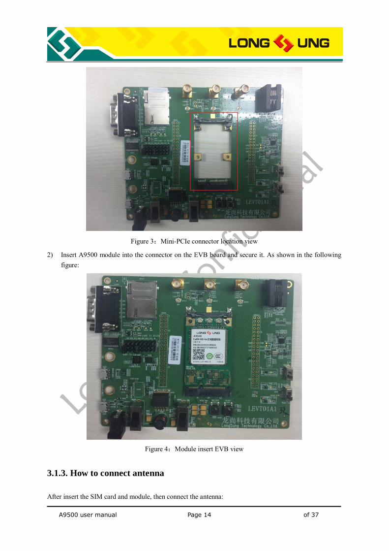
Figure 3:Mini-PCIe connector location view
2) Insert A9500 module into the connector on the EVB board and secure it. As shown in the following figure:
Figure 4:Module insert EVB view
3.1.3. How to connect antenna
After insert the SIM card and module, then connect the antenna:
A9500 user manual Page 15 of 37
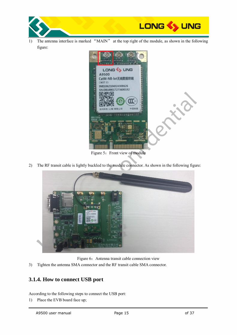
1) The antenna interface is marked “MAIN” at the top right of the module, as shown in the following figure:
Figure 5:Front view of module
2) The RF transit cable is lightly buckled to the module connector. As shown in the following figure:
Figure 6:Antenna transit cable connection view
3) Tighten the antenna SMA connector and the RF transit cable SMA connector.
3.1.4. How to connect USB port
According to the following steps to connect the USB port: 1) Place the EVB board face up;
A9500 user manual Page 16 of 37
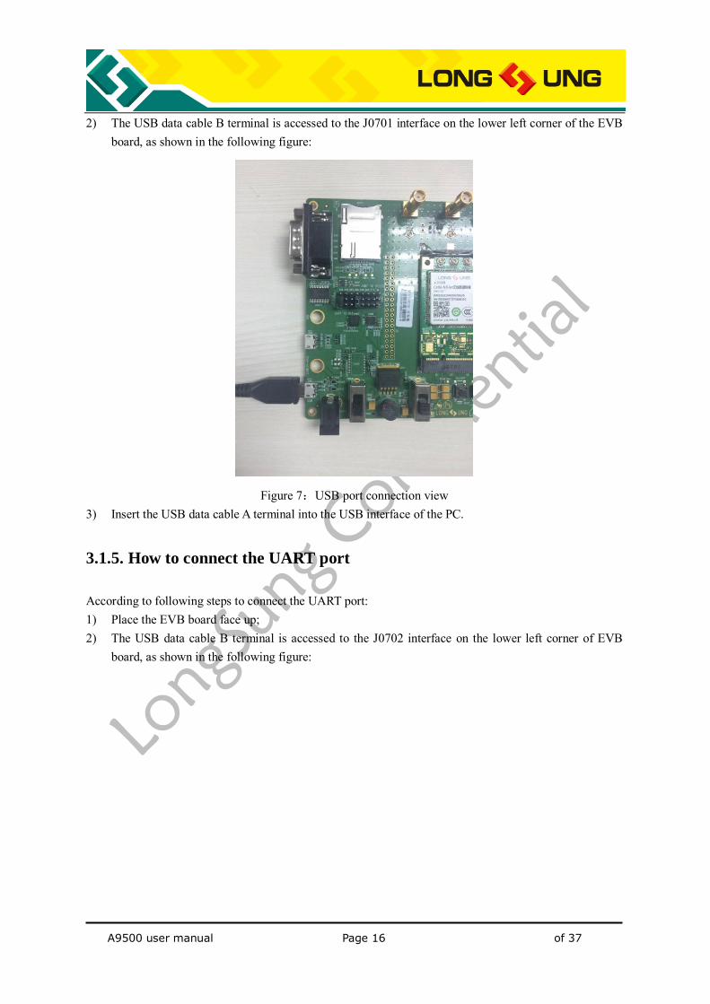
2) The USB data cable B terminal is accessed to the J0701 interface on the lower left corner of the EVB board, as shown in the following figure:
Figure 7:USB port connection view
3) Insert the USB data cable A terminal into the USB interface of the PC.
3.1.5. How to connect the UART port
According to following steps to connect the UART port: 1) Place the EVB board face up; 2) The USB data cable B terminal is accessed to the J0702 interface on the lower left corner of EVB
board, as shown in the following figure:
A9500 user manual Page 17 of 37
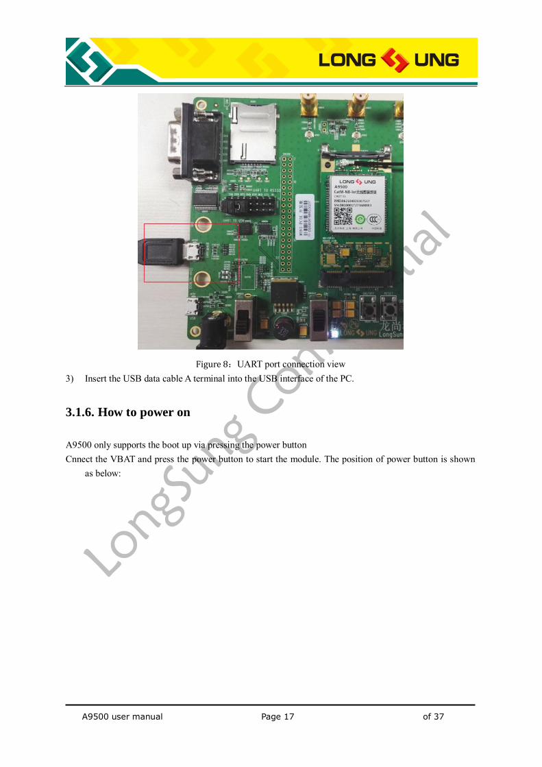
Figure 8:UART port connection view 3) Insert the USB data cable A terminal into the USB interface of the PC.
3.1.6. How to power on
A9500 only supports the boot up via pressing the power button Cnnect the VBAT and press the power button to start the module. The position of power button is shown
as below:
A9500 user manual Page 18 of 37
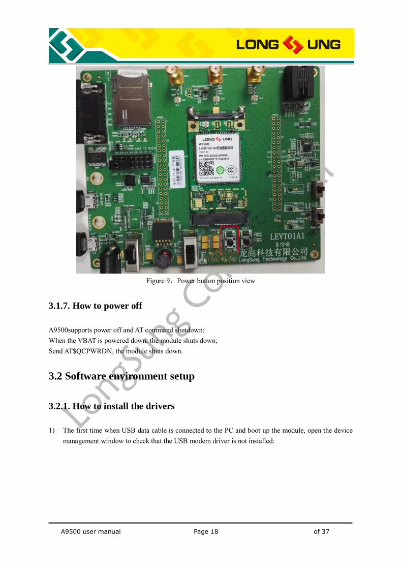
Figure 9:Power button position view
3.1.7. How to power off
A9500supports power off and AT command shutdown: When the VBAT is powered down, the module shuts down; Send AT$QCPWRDN, the module shuts down.
3.2 Software environment setup
3.2.1. How to install the drivers
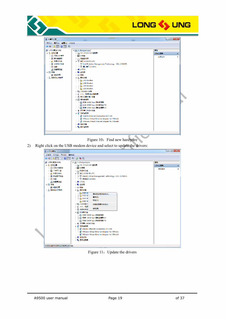
1) The first time when USB data cable is connected to the PC and boot up the module, open the device management window to check that the USB modem driver is not installed:
A9500 user manual Page 19 of 37
Figure 10:Find new hardware
2) Right click on the USB modem device and select to update the drivers:
Figure 11:Update the drivers
A9500 user manual Page 20 of 37
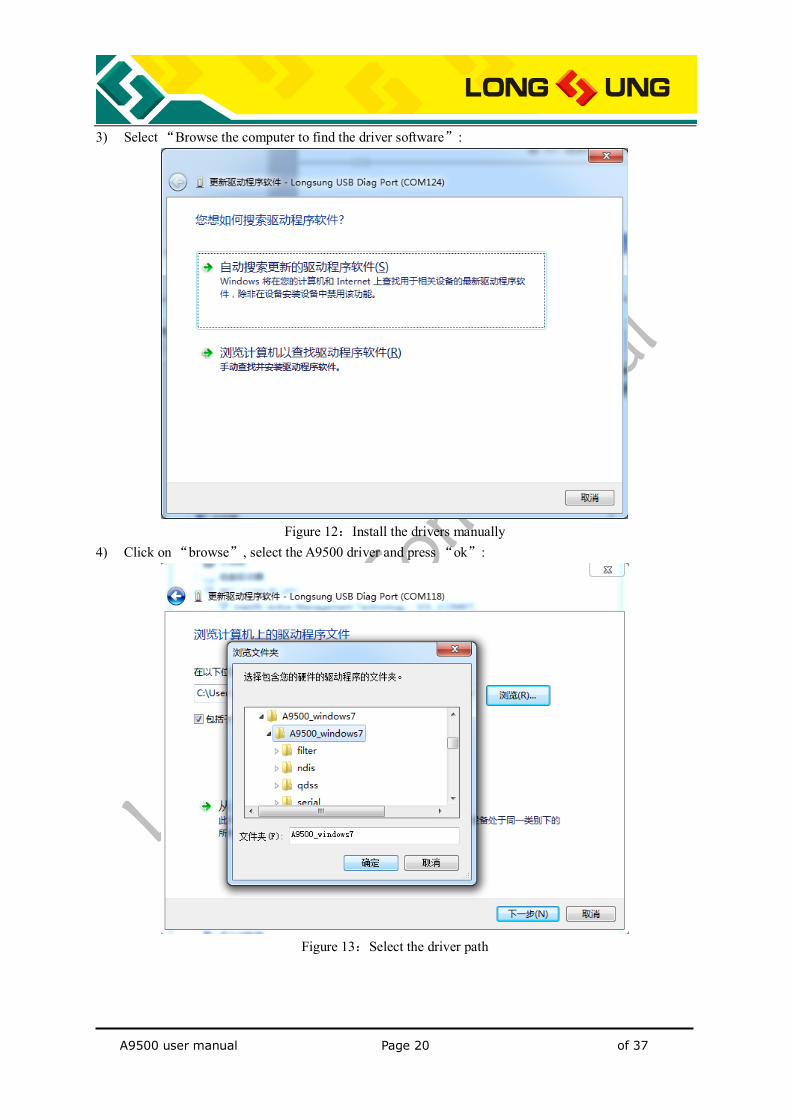
3) Select “Browse the computer to find the driver software”:
Figure 12:Install the drivers manually
4) Click on “browse”, select the A9500 driver and press “ok”:
Figure 13:Select the driver path
A9500 user manual Page 21 of 37
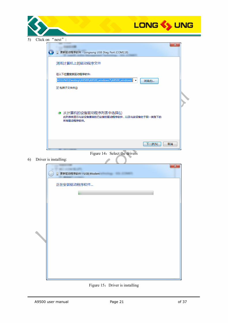
5) Click on “next”:
Figure 14:Select the drivers
6) Driver is installing:
Figure 15:Driver is installing
A9500 user manual Page 22 of 37
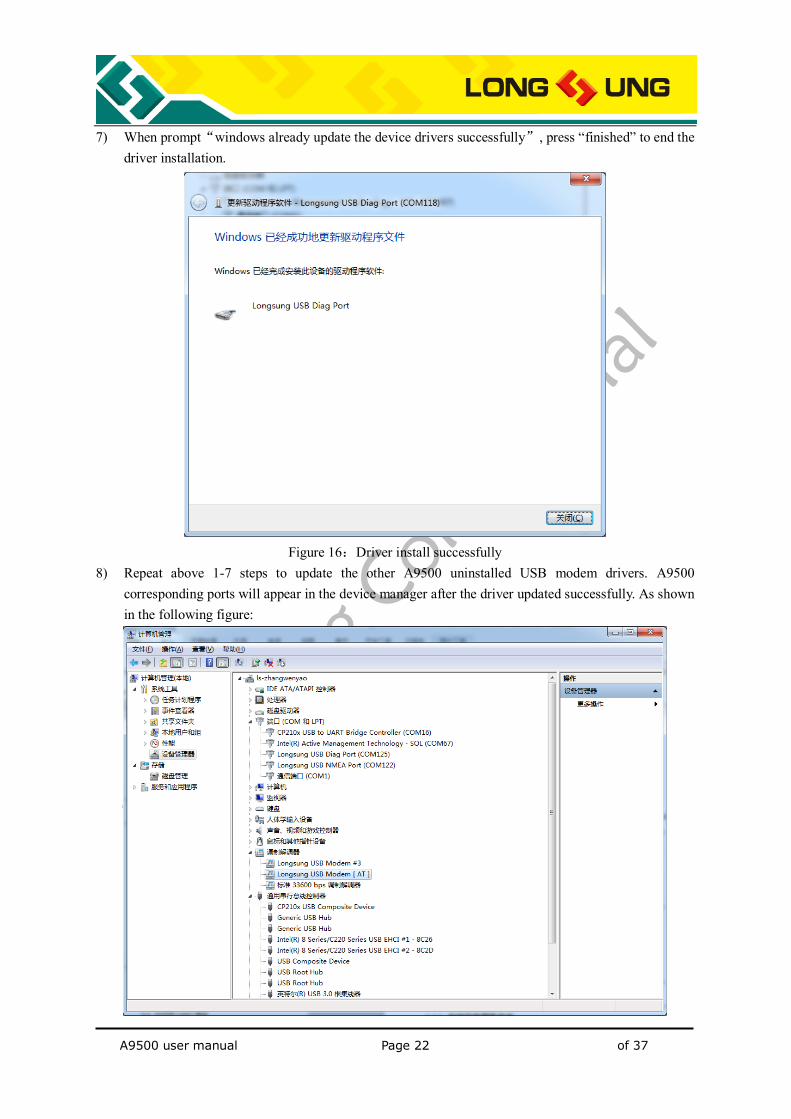
7) When prompt“windows already update the device drivers successfully”, press “finished” to end the driver installation.
Figure 16:Driver install successfully
8) Repeat above 1-7 steps to update the other A9500 uninstalled USB modem drivers. A9500 corresponding ports will appear in the device manager after the driver updated successfully. As shown in the following figure:
A9500 user manual Page 23 of 37
Figure 17:A9500 ports display in the device manager
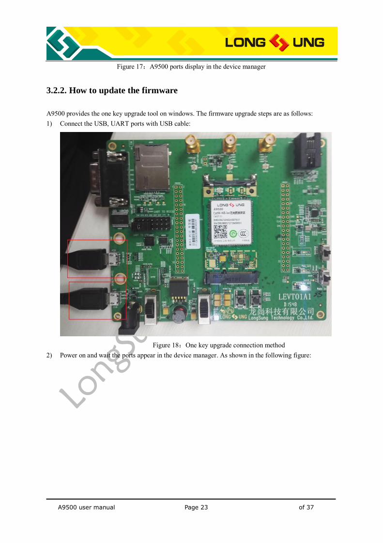
3.2.2. How to update the firmware
A9500 provides the one key upgrade tool on windows. The firmware upgrade steps are as follows: 1) Connect the USB, UART ports with USB cable:
Figure 18:One key upgrade connection method
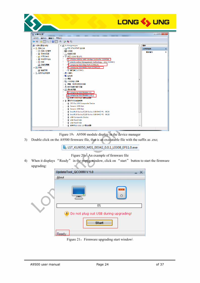
2) Power on and wait the ports appear in the device manager. As shown in the following figure:
A9500 user manual Page 24 of 37
Figure 19:A9500 module display in the device manager
3) Double click on the A9500 firmware file, that is an executable file with the suffix as .exe;
Figure 20:An example of firmware file
4) When it displays “Ready” in the popup window, click on “start” button to start the firmware upgrading:
Figure 21:Firmware upgrading start window\
A9500 user manual Page 25 of 37
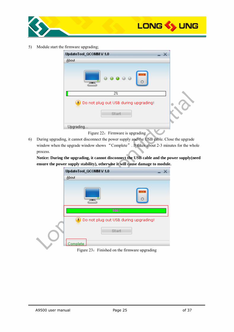
5) Module start the firmware upgrading;
Figure 22:Firmware is upgrading
6) During upgrading, it cannot disconnect the power supply and the USB cable. Close the upgrade window when the upgrade window shows “Complete”. It takes about 2-3 minutes for the whole process. Notice: During the upgrading, it cannot disconnect the USB cable and the power supply(need
ensure the power supply stability), otherwise it will cause damage to module.
Figure 23:Finished on the firmware upgrading
A9500 user manual Page 26 of 37
4. Test and Debug
The EVB board can be used for TCP/IP transport and internet connection; in addition to the USB communication, A9500 also supports UART mode communication. This chapter will describe these related functions.
4.1. How to use USB communication
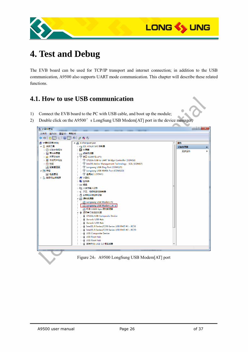
1) Connect the EVB board to the PC with USB cable, and boot up the module; 2) Double click on the A9500’s LongSung USB Modem[AT] port in the device manager;
Figure 24:A9500 LongSung USB Modem[AT] port
A9500 user manual Page 27 of 37
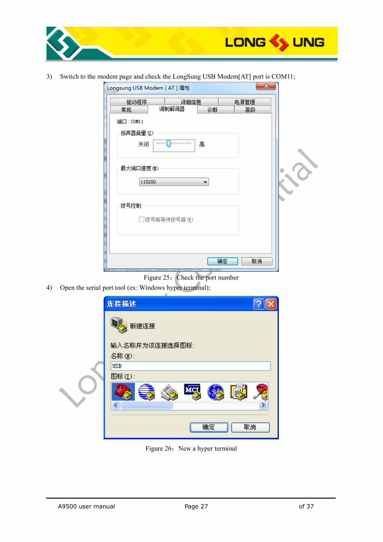
3) Switch to the modem page and check the LongSung USB Modem[AT] port is COM11;
Figure 25:Check the port number
4) Open the serial port tool (ex: Windows hyper terminal);
Figure 26:New a hyper terminal
A9500 user manual Page 28 of 37
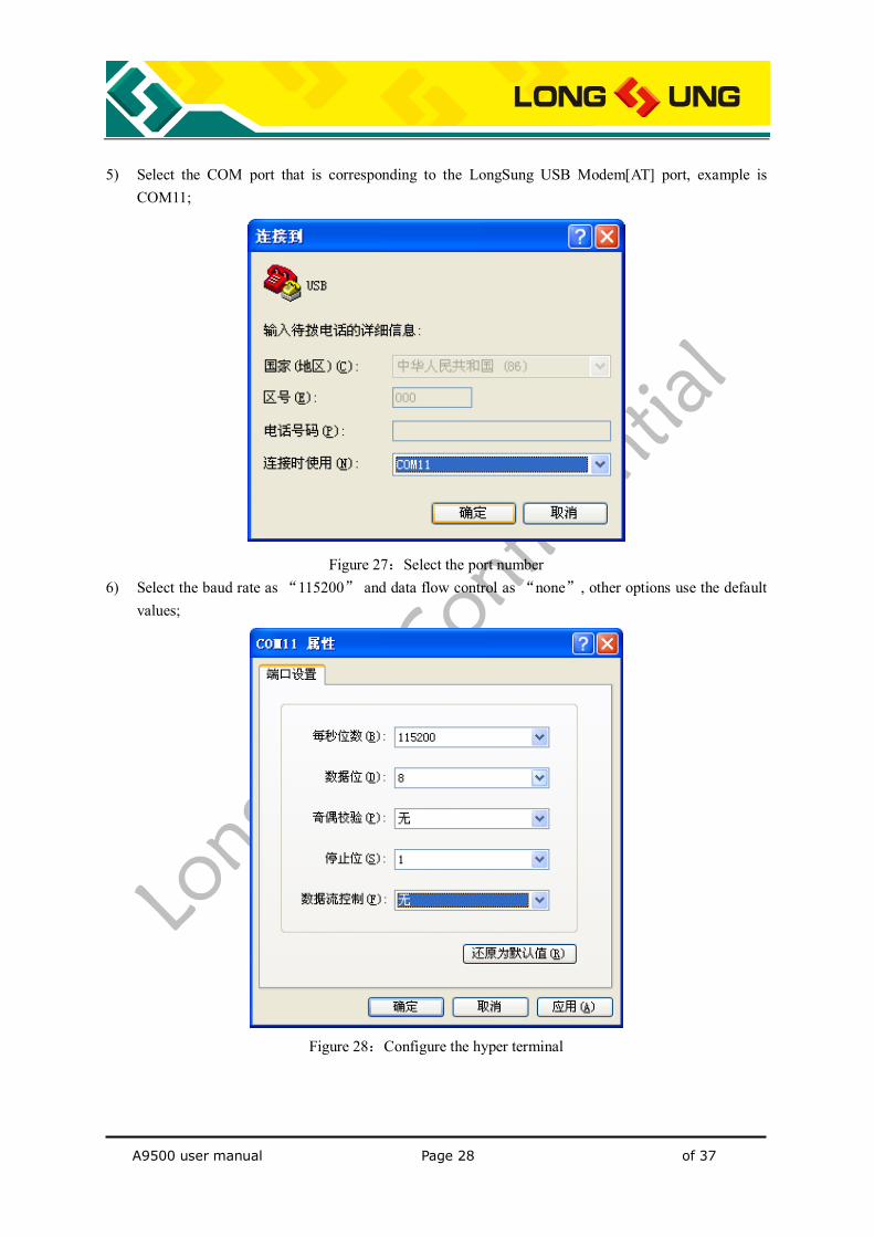
5) Select the COM port that is corresponding to the LongSung USB Modem[AT] port, example is
COM11;
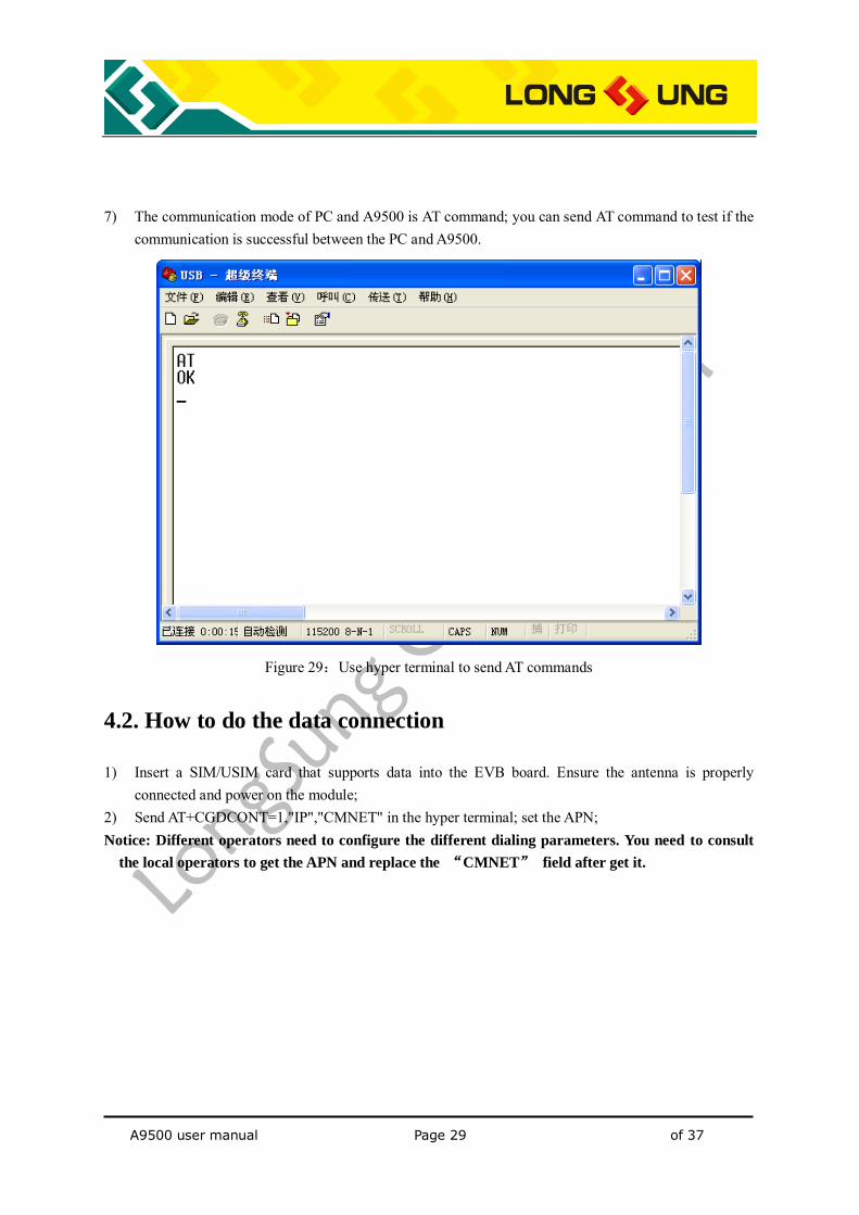
Figure 27:Select the port number 6) Select the baud rate as “115200” and data flow control as “none”, other options use the default
values;
Figure 28:Configure the hyper terminal
A9500 user manual Page 29 of 37
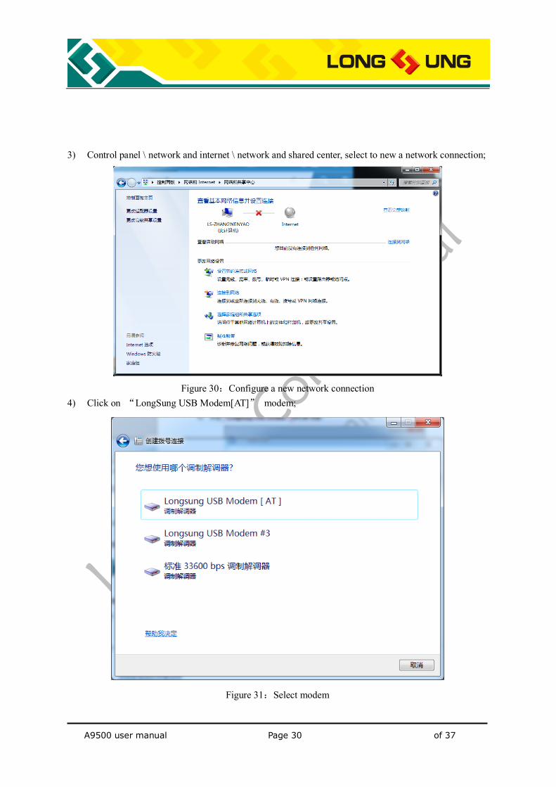
7) The communication mode of PC and A9500 is AT command; you can send AT command to test if the
communication is successful between the PC and A9500.
Figure 29:Use hyper terminal to send AT commands
4.2. How to do the data connection
1) Insert a SIM/USIM card that supports data into the EVB board. Ensure the antenna is properly connected and power on the module;
2) Send AT+CGDCONT=1,"IP","CMNET" in the hyper terminal; set the APN; Notice: Different operators need to configure the different dialing parameters. You need to consult
the local operators to get the APN and replace the “CMNET” field after get it.
A9500 user manual Page 30 of 37
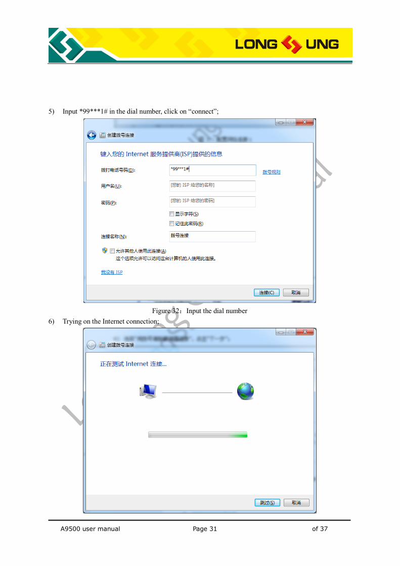
3) Control panel \ network and internet \ network and shared center, select to new a network connection;
Figure 30:Configure a new network connection
4) Click on “LongSung USB Modem[AT]” modem;
Figure 31:Select modem
A9500 user manual Page 31 of 37
5) Input *99***1# in the dial number, click on “connect”;
Figure 32:Input the dial number
6) Trying on the Internet connection;
A9500 user manual Page 32 of 37
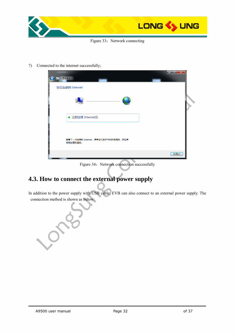
Figure 33:Network connecting 7) Connected to the internet successfully;
Figure 34:Network connection successfully
4.3. How to connect the external power supply
In addition to the power supply with USB cable, EVB can also connect to an external power supply. The connection method is shown as below:
A9500 user manual Page 33 of 37
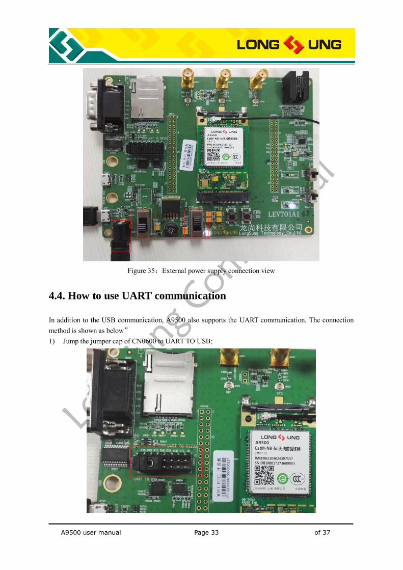
Figure 35:External power supply connection view
4.4. How to use UART communication
In addition to the USB communication, A9500 also supports the UART communication. The connection method is shown as below” 1) Jump the jumper cap of CN0600 to UART TO USB;

A9500 user manual Page 34 of 37
Figure 36:UART jumper cap configure 2) Connect the USB cable to the J0702 interface of the EVB board;
Figure 37:UART data cable connection view
3) Check the UART port is COM1;
Figure 38:Check the UART port
A9500 user manual Page 35 of 37
4) Open the serial port tool;
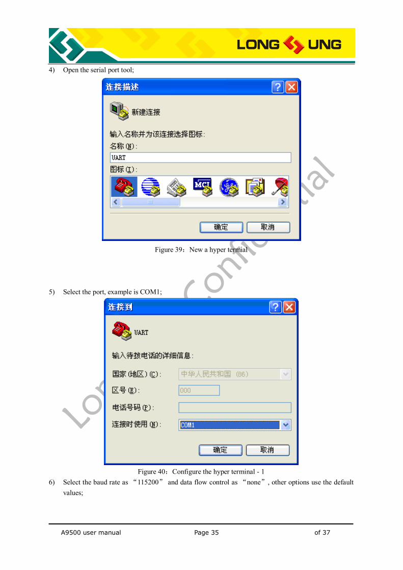
Figure 39:New a hyper termial
5) Select the port, example is COM1;
Figure 40:Configure the hyper terminal - 1
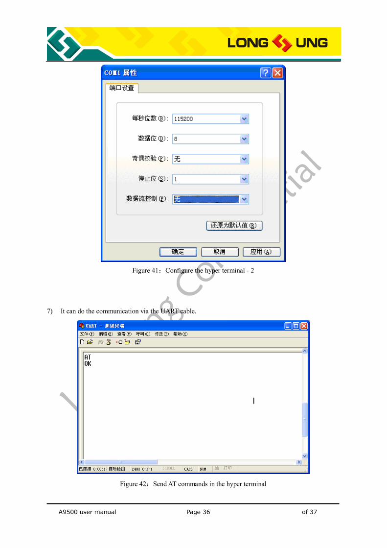
6) Select the baud rate as “115200” and data flow control as “none”, other options use the default values;
A9500 user manual Page 36 of 37
Figure 41:Configure the hyper terminal - 2
7) It can do the communication via the UART cable.
Figure 42:Send AT commands in the hyper terminal
A9500 user manual Page 37 of 37
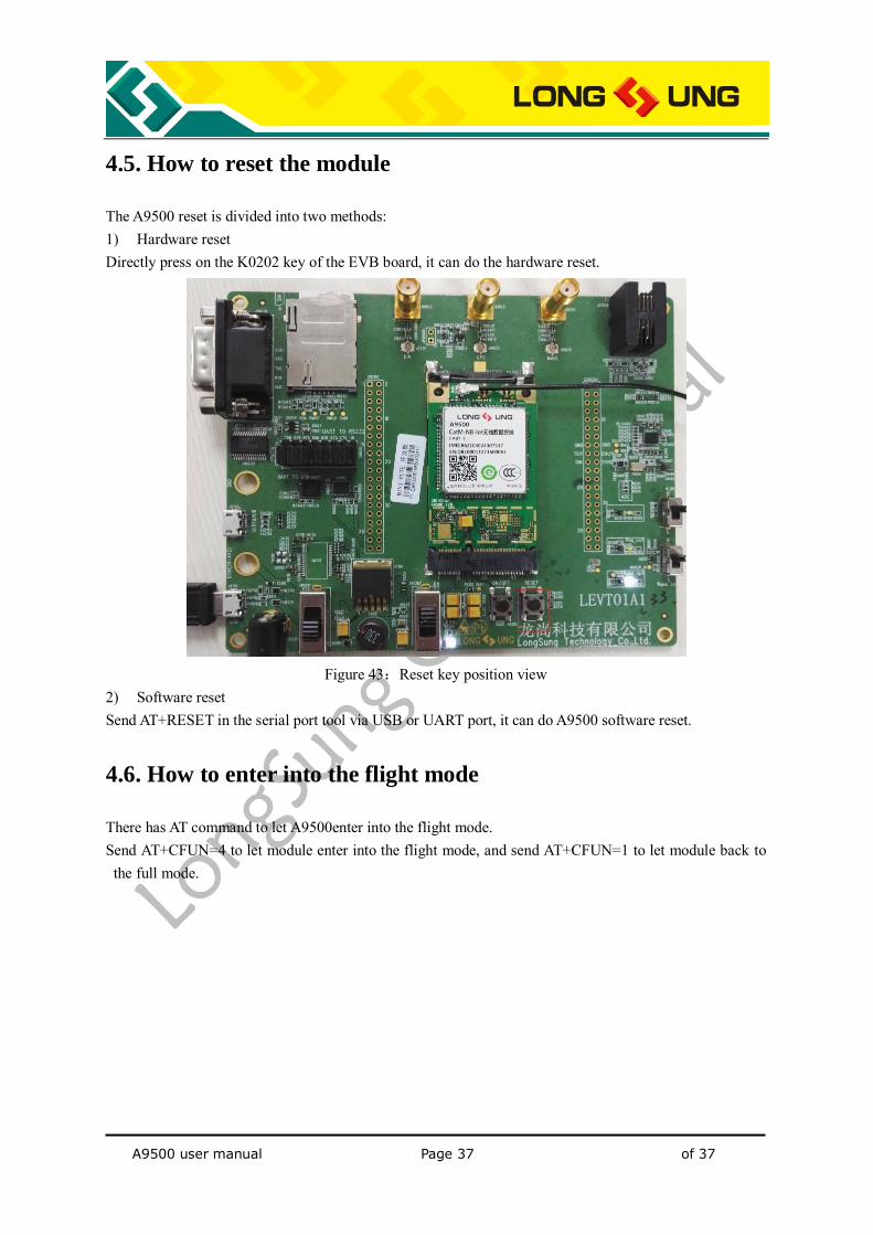
4.5. How to reset the module
The A9500 reset is divided into two methods: 1) Hardware reset Directly press on the K0202 key of the EVB board, it can do the hardware reset.
Figure 43:Reset key position view
2) Software reset Send AT+RESET in the serial port tool via USB or UART port, it can do A9500 software reset.
4.6. How to enter into the flight mode
There has AT command to let A9500enter into the flight mode. Send AT+CFUN=4 to let module enter into the flight mode, and send AT+CFUN=1 to let module back to the full mode.