Embed Size (px)
Citation preview

Mot
herb
oard
A7N8X-X
User Guide

ii
Checklist
Copyright © 2005 ASUSTeK COMPUTER INC. All Rights Reserved.No part of this manual, including the products and software described in it, may bereproduced, transmitted, transcribed, stored in a retrieval system, or translated into anylanguage in any form or by any means, except documentation kept by the purchaser forbackup purposes, without the express written permission of ASUSTeK COMPUTER INC.(“ASUS”).
Product warranty or service will not be extended if: (1) the product is repaired, modified oraltered, unless such repair, modification of alteration is authorized in writing by ASUS; or (2)the serial number of the product is defaced or missing.
ASUS PROVIDES THIS MANUAL “AS IS” WITHOUT WARRANTY OF ANY KIND, EITHEREXPRESS OR IMPLIED, INCLUDING BUT NOT LIMITED TO THE IMPLIED WARRANTIESOR CONDITIONS OF MERCHANTABILITY OR FITNESS FOR A PARTICULAR PURPOSE.IN NO EVENT SHALL ASUS, ITS DIRECTORS, OFFICERS, EMPLOYEES OR AGENTS BELIABLE FOR ANY INDIRECT, SPECIAL, INCIDENTAL, OR CONSEQUENTIAL DAMAGES(INCLUDING DAMAGES FOR LOSS OF PROFITS, LOSS OF BUSINESS, LOSS OF USEOR DATA, INTERRUPTION OF BUSINESS AND THE LIKE), EVEN IF ASUS HAS BEENADVISED OF THE POSSIBILITY OF SUCH DAMAGES ARISING FROM ANY DEFECT ORERROR IN THIS MANUAL OR PRODUCT.
SPECIFICATIONS AND INFORMATION CONTAINED IN THIS MANUAL ARE FURNISHEDFOR INFORMATIONAL USE ONLY, AND ARE SUBJECT TO CHANGE AT ANY TIMEWITHOUT NOTICE, AND SHOULD NOT BE CONSTRUED AS A COMMITMENT BY ASUS.ASUS ASSUMES NO RESPONSIBILITY OR LIABILITY FOR ANY ERRORS ORINACCURACIES THAT MAY APPEAR IN THIS MANUAL, INCLUDING THE PRODUCTSAND SOFTWARE DESCRIBED IN IT.
Products and corporate names appearing in this manual may or may not be registeredtrademarks or copyrights of their respective companies, and are used only for identification orexplanation and to the owners’ benefit, without intent to infringe.
E1875
Revised Edition V3January 2005

iii
Fea
ture
s
ContentsNotices ............................................................................................ v
Safety information .......................................................................... vi
ASUS contact information ............................................................ viii
A7N8X-X specifications summary .................................................. ix
Chapter 1: Motherboard Info1.1 Welcome! ........................................................................... 1-2
1.2 Package contents ............................................................... 1-2
1.3 Motherboard components .................................................. 1-3
1.4 Motherboard layout ............................................................ 1-6
1.5 Before you proceed ............................................................ 1-7
1.6 Central Processing Unit (CPU) ........................................... 1-7
1.7 System memory ................................................................. 1-81.7.1 Installing a DIMM ................................................... 1-8
1.8 Expansion slots .................................................................. 1-81.8.1 Configuring an expansion card .............................. 1-81.8.2 Standard Interrupt Assignments ............................ 1-91.8.3 AGP slot ................................................................. 1-9
1.9 Jumpers ............................................................................ 1-10
1.10 Connectors ....................................................................... 1-12
Chapter 2: BIOS Information2.1 Managing and updating your BIOS .................................... 2-2
2.1.1 Using the computer system for the first time ......... 2-22.1.2 Updating BIOS procedures .................................... 2-3
2.2 BIOS Setup program .......................................................... 2-62.2.1 BIOS menu bar ...................................................... 2-72.2.2 Legend bar ............................................................. 2-7
2.3 Main Menu.......................................................................... 2-92.3.1 Primary Master/Slave .......................................... 2-102.3.2 Secondary Master/Slave ...................................... 2-12
2.4 Advanced Menu ............................................................... 2-132.4.1 Advanced BIOS Features .................................... 2-142.4.2 Advanced Chipset Features ................................ 2-15

iv
Safeguards
Contents
2.4.3 Integrated Peripherals ......................................... 2-182.4.4 Power Management Setup .................................. 2-202.4.5 PnP / PCI Configurations ..................................... 2-22
2.5 Security Menu .................................................................. 2-23
2.6 Hardware Monitor Menu ................................................... 2-24
2.7 Exit Menu ......................................................................... 2-26
Chapter 3: Starting Up3.1 Install an operating system................................................. 3-2
3.2 Support CD information ...................................................... 3-23.2.1 Running the support CD ........................................ 3-23.2.2 Drivers menu ......................................................... 3-33.2.3 Utilities menu ......................................................... 3-3
3.2.4 ASUS Contact Information ................................................. 3-4

v
Notices
Federal Communications Commission Statement
This device complies with Part 15 of the FCC Rules. Operation is subject tothe following two conditions:
• This device may not cause harmful interference, and
• This device must accept any interference received including interferencethat may cause undesired operation.
This equipment has been tested and found to comply with the limits for aClass B digital device, pursuant to Part 15 of the FCC Rules. These limitsare designed to provide reasonable protection against harmful interferencein a residential installation. This equipment generates, uses and can radiateradio frequency energy and, if not installed and used in accordance withmanufacturer’s instructions, may cause harmful interference to radiocommunications. However, there is no guarantee that interference will notoccur in a particular installation. If this equipment does cause harmfulinterference to radio or television reception, which can be determined byturning the equipment off and on, the user is encouraged to try to correct theinterference by one or more of the following measures:
• Reorient or relocate the receiving antenna.
• Increase the separation between the equipment and receiver.
• Connect the equipment to an outlet on a circuit different from that towhich the receiver is connected.
• Consult the dealer or an experienced radio/TV technician for help.
Canadian Department of Communications Statement
This digital apparatus does not exceed the Class B limits for radio noiseemissions from digital apparatus set out in the Radio InterferenceRegulations of the Canadian Department of Communications.
This class B digital apparatus complies with Canadian ICES-003.
The use of shielded cables for connection of the monitor to thegraphics card is required to assure compliance with FCC regulations.Changes or modifications to this unit not expressly approved by theparty responsible for compliance could void the user’s authority tooperate this equipment.
vi
Safety information
Electrical safety
• To prevent electrical shock hazard, disconnect the power cable fromthe electrical outlet before relocating the system.
• When adding or removing devices to or from the system, ensure thatthe power cables for the devices are unplugged before the signalcables are connected. If possible, disconnect all power cables from theexisting system before you add a device.
• Before connecting or removing signal cables from the motherboard,ensure that all power cables are unplugged.
• Seek professional assistance before using an adpater or extensioncord. These devices could interrupt the grounding circuit.
• Make sure that your power supply is set to the correct voltage in yourarea. If you are not sure about the voltage of the electrical outlet youare using, contact your local power company.
• If the power supply is broken, do not try to fix it by yourself. Contact aqualified service technician or your retailer.
Operation safety• Before installing the motherboard and adding devices on it, carefully
read all the manuals that came with the package.
• Before using the product, make sure all cables are correctly connectedand the power cables are not damaged. If you detect any damage,contact your dealer immediately.
• To avoid short circuits, keep paper clips, screws, and staples away fromconnectors, slots, sockets and circuitry.
• Avoid dust, humidity, and temperature extremes. Do not place theproduct in any area where it may become wet.
• Place the product on a stable surface.
• If you encounter technical problems with the product, contact aqualified service technician or your retailer.

vii
Conventions used in this guideTo make sure that you perform certain tasks properly, take note of thefollowing symbols used throughout this manual.
Where to find more informationRefer to the following sources for additional information and for productand software updates.
1. ASUS WebsitesThe ASUS websites worldwide provide updated information on ASUShardware and software products. The ASUS websites are listed in theASUS Contact Information on page viii.
2. Optional Documentation
Your product package may include optional documentation, such aswarranty flyers, that may have been added by your dealer. Thesedocuments are not part of the standard package.
WARNING/DANGER: Information to prevent injury to yourselfwhen trying to complete a task.
CAUTION: Information to prevent damage to the componentswhen trying to complete a task.
IMPORTANT: Information that you MUST follow to complete atask.
NOTE: Tips and additional information to aid in completing a task.

viii
ASUS contact informationASUSTeK COMPUTER INC. (Asia-Pacific)Address 15 Li-Te Road, Peitou, Taipei, Taiwan 112Telephone +886-2-2894-3447Web site www.asus.com.twTechnical SupportTelephone(MB/Component) +886-2-2890-7121 (English) (Notebook) +886-2-2890-7122 (English) (Server/PC) +886-2-2890-7123 (English) (Networking) +886-2-2890-7902 (English)Support fax +886-2-2890-7698
ASUS COMPUTER INTERNATIONAL (America)Address 44370 Nobel Drive, Fremont, CA 94538, USAFax +1-510-608-4555E-mail [email protected] site usa.asus.comTechnical SupportTelephone (General) +1-502-995-0883 (Notebook) +1-510-739-3777Support fax +1-502-933-8713Support e-mail [email protected]
ASUS COMPUTER GmbH (Germany and Austria)Address Harkort Str. 25, D-40880 Ratingen, GermanyTelephone +49-2102-95990Fax +49-2102-959911Online contact www.asuscom.de/salesTechnical SupportTelephone +49-2102-95990Fax +49-2102-959911Online support www.asuscom.de/supportWeb site www.asuscom.de/news

ix
A7N8X-X specifications summaryCPU
Chipset
Front Side Bus (FSB)
Memory
Expansion slots
IDE
Audio
LAN
Special Features
Back Panel I/O Ports
Internal I/OConnectors
(continued on the next page)
Socket A for AMD Duron™/Athlon™/Athlon™ XP 3200+ orhigher400/333 MHz FSB Support
Northbridge: NVIDIA® nForce2 400Southbridge: NVIDIA® nForce2 MCP
400/333/266/200Mhz
3 x 184-pin DDR DIMM SocketsMax. 3 GB unbuffered PC3200/2700/2100/1600 non-ECCDDR RAM memory.(Visit ASUS website for latest qualified DDR400 module list.)
5 x PCI1 x AGP 8X (1.5V only)
2 x UltraDMA 133/100/66/33
Realtek ALC650 6CH with built-in HP amplifier
1 PortMCP integrated NVIDIA MAC + Realtek 8201BL PHY
ASUS Q-Fan TechnologyASUS C.O.P. (CPU Overheating Protection)Power Loss RestartCPU ThrottleSupport S/PDIF in/out (optional)
1 x Parallel1 x Serial1 x PS/2 Keyboard1 x PS/2 Mouse1 x RJ45 port1 x Audio I/O4 x USB 2.0
1 x USB 2.0 connector supports additional 2 USB 2.0 ports(optional)Game connector (optional)CPU/Power/Chassis FAN connectors20-pin ATX Power connectorIDE LED connector, Power LED connectorChassis Intrusion, SIRHeadphone (optional)Front MIC (optional)CD / AUX / Modem audio inFront Panel Audio connector (optional)
x
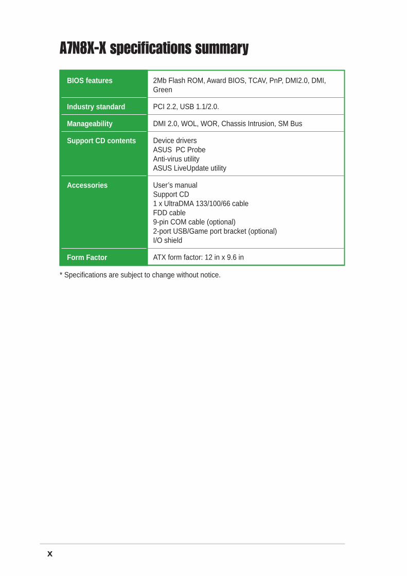
A7N8X-X specifications summary
BIOS features
Industry standard
Manageability
Support CD contents
Accessories
Form Factor
* Specifications are subject to change without notice.
2Mb Flash ROM, Award BIOS, TCAV, PnP, DMI2.0, DMI,Green
PCI 2.2, USB 1.1/2.0.
DMI 2.0, WOL, WOR, Chassis Intrusion, SM Bus
Device driversASUS PC ProbeAnti-virus utilityASUS LiveUpdate utility
User’s manualSupport CD1 x UltraDMA 133/100/66 cableFDD cable9-pin COM cable (optional)2-port USB/Game port bracket (optional)I/O shield
ATX form factor: 12 in x 9.6 in

1-1ASUS A7N8X-X Motherboard
This chapter gives information about the ASUSA7N8X-X motherboard that came with thesystem.This chapter includes the motherboardlayout, jumper settings, and connector locations.
Mo
ther
bo
ard
Info
Chapter 1

1-2
1.1 Welcome!Thank you for buying the ASUS® A7N8X-X motherboard!
The ASUS A7N8X-X motherboard is loaded with the most advanced technologies todeliver the maximum performance for socket A processors. This motherboard is loadedwith value-added features for guaranteed consumer satisfaction. Unique ASUSfeatures such as ASUS C.O.P., ASUS Q-Fan Technology and more are included toensure the best user experience and value in a motherboard. For future upgrades orsystem reconfiguration, this chapter provides technical information about themotherboard.
Before you start installing the motherboard and hardware devices on it, check theitems in your package with the list below.
1.2 Package contentsCheck your ASUS A7N8X-X package for the following items.
ASUS A7N8X-X motherboardATX form factor: 12 in x 9.6 in
ASUS A7N8X-X series support CD
40-pin 80-conductor ribbon cable for UltraDMA/66/100/133 IDE drives
Ribbon cable for a 3.5-inch floppy drive
Bag of extra jumper caps
I/O shield
User’s Manual

ASUS A7N8X-X Motherboard 1-3
1.3 Motherboard components2 3 51
14
4
9
7
6
8
12
18
13
16
17
1011
15
19 20
28 26
22
23
24
27 25
21

1-4 Chapter 1: Motherboard Information
12
CPU Sockets. Socket 462 (Socket A) Zero Insertion Force (ZIF) socket forthe AMD Duron™/Athlon™/Athlon XP™ 3000+ processors.
NorthBridge Controller. The NVIDIA® nForce2™ 400 North Bridgecontroller chipset. The controller supports a 64-bit DDR memory controllerand up to 3 GB of 400/333/266/200MHz DDR memory.
DDR DIMM Sockets. Equipped with three Double Data Rate Dual InlineMemory Module (DDR DIMM) sockets to support up to 3GB of DDRDRAM, the newest memory standard with the highest bandwidth andlowest latency currently available. This memory technology supplies datatransfer rates up to 3.2 GB/s for 400MHz DDR SDRAM and 2.7GB/s for333MHz DDR SDRAM.
ATX power connector. This standard 20-pin connector connects to anATX 12V power supply. The power supply must have at least 1A on the+5V standby lead (+5VSB).
Floppy Disk connector. This connector connects the provided ribboncable for the floppy disk drive. One side of the connector is slotted toprevent incorrect insertion of the floppy disk cable.
IDE Connectors. These dual-channel bus master IDE connectors supportup to four Ultra DMA133/100/66, PIO Modes 3 & 4 IDE devices. Both theprimary(blue) and secondary(black) connectors are slotted to preventincorrect insertion of the IDE ribbon cable.
Flash ROM. This 2Mb firmware contains the programmable BIOSprogram. (Refer to section “2.1 Managing and updating your BIOS” onpage 2-2 for more information)
South bridge controller. Features the brand new nVidia® nForce2™ MCPintegrated peripheral South Bridge controller operates at 800MB/sec tocommunicate with the North Bridge for maximum bandwith required forPCI, USB and support for Fast Ethernet devices. The controller supportsstandard UltraDMA133/100/66/33 and separate data paths for each IDEchannel are built-in for up to two IDE devices. The controller supports sixUSB ports, one LAN port and is PCI rev2.2 compliant.
Super I/O chipset. ITE IT8708 offers support for a variety of I/O functions.Provides two high-speed UART compatible serial ports and one parallelport with EPP and ECP capabilities. UART2 can also be directed fromCOM2 to the Infrared Module for wireless connections. The Super I/Ocontroller supports a floppy disk drive, PS/2 keyboard, and PS/2 mouse.
COM2 Header. This 9-pin connects to a COM2 port.
GAME port header. This header connects to a GAME port module.
ASUS ASIC. This chip performs multiple system functions that includehardware and system voltage monitoring among others.
10
1
2
3
4
5
6
7
8
9
11

ASUS A7N8X-X Motherboard 1-5
Onboard LED. This onboard LED lights up if there is a standby power onthe motherboard. This LED acts as a reminder to turn off the system powerbefore plugging or unplugging devices.
PCI slots. These 32-bit PCI 2.2 expansion slots support bus master PCIcards like SCSI or LAN cards with 133MB/s maximum output.
S/PDIF connector. This header connects to the S/PDIF bracket. (optional)
Audio CODEC. The Realtek 6-channel CODEC is an AC’97 compliantaudio CODEC designed for PC multimedia systems.
LAN chip. The MCP integrated NVIDIA® MAC + Realtek 8201BL PHYFast Ethernet controller allows connection to a Local Area Network (LAN)through a network hub.
AGP Slot. This Accelerated Graphics Port (AGP) slot only supports 1.5VAGP 8X mode graphics cards for 3D graphical applications.
PS/2 mouse port. This green 6-pin connector is for a PS/2 mouse.
Parallel port. This 25-pin port connects a parallel printer, a scanner, orother devices.
RJ-45 port. Using the NVIDIA® LAN 10/100 Mbps fast ethernet controller,this port allows connection to a Local Area Network (LAN) through anetwork hub.
Line In jack. This Line In (light blue) jack connects a tape player or otheraudio sources.
Line Out jack. This Line Out (lime) jack connects a headphone or aspeaker.
Microphone jack. This Mic (pink) jack connects a microphone.
USB 2.0 ports. These two 4-pin Universal Serial Bus 2.0 (USB 2.0) portsare available for connecting USB devices such as a mouse and PDA.
Serial ports. This port connects to your serial mouse and other serialdevices.
USB 2.0 ports. These two 4-pin Universal Serial Bus 2.0 (USB 2.0) portsare available for connecting USB devices such as a mouse and PDA.
PS/2 keyboard port. This purple 6-pin connector is for a PS/2 keyboard.
14
15
16
17
18
19
20
21
22
23
24
25
13
26
27
28

1-6 Chapter 1: Motherboard Information
1.4 Motherboard layout24.5cm (9.64in)
30.5
cm (
12.0
in)
PR
I_ID
E1
FLO
PP
Y1
A7N8X-X
nForce2MCP
Chipset
ASUSASIC
with HardwareMonitor
Accelerated Graphics Port (AGP)
nVidianForce2
400Chipset
CR2032 3VLithium Cell
CMOS Power
PWR_LED1
DD
R D
IMM
1 (6
4/72
bit,
184
-pin
mod
ule)
0 1D
DR
DIM
M2
(64/
72 b
it, 1
84-p
in m
odul
e)2 3
AT
X P
ower
Con
nect
or
SuperI/O
2MbBIOS
DD
R D
IMM
3 (6
4/72
bit,
184
-pin
mod
ule)
4 5
®
Socket 462
PCI 1
PS/2T: MouseB: Keyboard
RealtekRTL8201
COM2
CTRL_PANEL1
USB56
PWRTMP1
CHASSIS1
IDELED1
CLRTC1
CHA_FAN1
CPU_FAN1
PCI 2
PCI 3
PCI 4
PCI 5
SE
C_I
DE
1
PAR
AL
LE
L P
OR
T
COM1
CD1
AUX1
MODEM1
KBPWR1
RJ-45Top:
USB1USB2
Bottom:
USBPWR_12
IR_CON1
USBPWR_56 GAME1
SPDIF1
AudioCodec
FPAUDIO1
Below:Mic InCenter:Line OutTop:Line In
USBPWR_34
CPU_FSB
USB3USB4

ASUS A7N8X-X Motherboard 1-7
1.5 Before you proceedTake note of the following precautions before you install motherboard componentsor change any motherboard settings.
1. Unplug the power cord from the wall socket before touching anycomponent.
2. Use a grounded wrist strap or touch a safely grounded object or toa metal object, such as the power supply case, before handlingcomponents to avoid damaging them due to static electricity.
3. Hold components by the edges to avoid touching the ICs on them.
4. Whenever you uninstall any component, place it on a groundedantistatic pad or in the bag that came with the component.
5. Before you install or remove any component, ensure that theATX power supply is switched off or the power cord isdetached from the power supply. Failure to do so may causesevere damage to the motherboard, peripherals, and/orcomponents.
1.6 Central Processing Unit (CPU)
A7N8X-X®
A7N8X-X Socket 462
AMD™ CPUCPU NOTCH
LOCK
CPU NOTCHTO INNERCORNER
LEVER
The motherboard provides a Socket A (462) for CPU installation. AMD processorsoffer gigahertz speeds to support all the latest computing platforms and applications.The A7N8X-X supports Athlon™ XP processors with “QuantiSpeed” data processing,large data caches, 3D enhancements and 400/333/266Mhz bus speeds.
Each AMD CPU has a “marked” corner. This corner is usually indicated with a notch,and/or a golden square or triangle. Refer to this indicator while orienting the CPU.
Do not use processors with core speeds of less than 1GHz on thismotherboard.

1-8 Chapter 1: Motherboard Information
1.8 Expansion slotsThe A7N8X-X motherboard has six (6) expansion slots. The following sub-sectionsdescribe the slots and the expansion cards that they support.
1.8.1 Configuring an expansion card
1.7 System memoryThe motherboard has three Double Data Rate (DDR) DIMM sockets that supportsup to 3GB non-ECC PC3200/2700/2100/1600 DDR..
1. DIMMs with more than 8 devices on each side of the module arenot supported.
2. Make sure the memory frequency and bus frequency setting in theBIOS are the same or set to [Auto] ensure system stability.
3. A DDR DIMM is keyed with a notch so that it fits in only onedirection. DO NOT force a DIMM into a socket to avoid damagingthe DIMM.
4. Visit ASUS website (www.asus.com) for latest DDR400 QualifiedVendor List.
A7N8X-X®
A7N8X-X 184-Pin DDRDIMM Sockets
80 Pins
104 Pins
Some expansion cards need an IRQ to operate. Generally, an IRQ must be exclusivelyassigned to one function at a time. In a standard design configuration, 16 IRQs areavailable but most are already in use.
1.7.1 Installing a DIMM1. Unlock a DIMM socket by pressing the retaining clips outward.
2. Align a DIMM on the socket. Make sure the notches on the DIMM exactly match the notches in the socket.
3. Firmly insert the DIMM into the socket until the retaining clips lock into place.

ASUS A7N8X-X Motherboard 1-9
1.8.2 Standard Interrupt AssignmentsIRQ Standard Function
0 System Timer 1 Keyboard Controller 2 Programmable Interrupt Controller 3* USB Universal Host Controller 4* Communications Port (COM1) 5* Onboard Audio 6 Standard Floppy Disk Controller 7* Printer Port (LPT1) 8 System CMOS/Real Time Clock 9* Onboard LAN10* USB Universal Host Controller11* External AGP card12* PS/2 Compatible Mouse Port13 Numeric Data Processor14* Primary Ultra ATA Controller15* Secondary Ultra ATA Controller
*These IRQs are usually available for ISA or PCI devices.
IRQ assignments for this motherboard
A B C DPCI slot 1 shared — — —PCI slot 2 — — — usedPCI slot 3 — — used —PCI slot 4 — used — —PCI slot 5 shared — — —
1.8.3 AGP slotThis motherboard has an Accelerated Graphics Port (AGP) slot that supports+1.5V AGP 8X cards. Note the notches on the card golden fingers to ensure thatthey fit the AGP slot on your motherboard.
A7N8X-X®
A7N8X-X Accelerated Graphics Port (AGP)
Keyed for 1.5v
Normally, 6 IRQs are free for expansion cards. Sometimes IRQs are “shared” bymore than one function; in this case, IRQ assignments are swapped automatically oradjusted through the BIOS firmware.

1-10 Chapter 1: Motherboard Information
1.9 JumpersThis section describes and illustrates the jumpers on the motherboard.
1. USB device wake-up (3-pin USBPWR_12,USBPWR_34,USBPWR_56)
Set these jumpers to +5V to wake up the computer from S1 sleep mode(CPU stopped, DRAM refreshed, system running in low power mode) usingthe connected USB devices. Set to +5VSB to wake up from S3 sleep mode(no power to CPU, DRAM in slow refresh, power supply in reduced powermode). Both jumpers are set to pins 1-2 (+5V) by default because not allcomputers have the appropriate power supply to support this feature.
The USBPWR_12 and USBPWR_34 jumpers are for the rear USB port.USBPWR_56 is for the internal USB header that you can connect to the frontUSB ports.
This feature requires a power supply that can provide at least 2A onthe +5VSB lead when these jumpers are set to +5VSB. Otherwise, thesystem does not power up.
The total current consumed must NOT exceed the power supplycapability (+5VSB) whether under normal condition or in sleep mode.
A7N8X-X®
A7N8X-X USB Device Wake Up
USBPWR_12USBPWR_34
USBPWR_56
(Default)+5V
1 2
+5VSB
2 3
12
32
(Default)+5V +5VSB
2. Central Processing Unit FSB (CPU_FSB)
This jumper when set to 1-2 pins (default), enable support for Front Side Bus400/333/266. When set to pins 2-3, it sets support for FSB 200 only.
A7N8X-X®
A7N8X-X CPU FSB Jumper Setting
CPU_FSB
FSB400/333/266 FSB200(Default)
12
32

ASUS A7N8X-X Motherboard 1-11
3. Clear RTC RAM (CLRTC1) (optional)
This jumper clears the Real Time Clock (RTC) RAM of date, time and systemsetup parameters in CMOS. The RAM data in CMOS is powered by theonboard button cell battery.
To erase the RTC RAM:
1. Turn OFF the computer and unplug the power cord.2. Remove the battery.3. Move the jumper caps from [1-2] to [2-3] momentarily. Replace the
jumper cap to the original position, [1-2].4. Re-install the battery.5. Plug the power cord and turn ON the computer.6. Hold down the <Del> key during the boot process and enter BIOS setup
to re-enter data.
A7N8X-X®
A7N8X-X Clear RTC RAM
CLRTC1
Normal Clear CMOS(Default)
2 31 2
4. Keyboard power (3-pin KBPWR1)
This jumper allows you to enable or disable the keyboard wake-up feature. Setthis jumper to pins 2-3 (+5VSB) if you wish to wake up the computer when youpress a key on the keyboard (the default value is [Disabled]). This featurerequires an ATX power supply that can supply at least 1A on the +5VSB lead,and a corresponding setting in the BIOS (see section 2.5.1 Power Up Control).
A7N8X-X®
A7N8X-X Keyboard Power Setting
KBPWR1
(Default)+5V
1 2
+5VSB
2 3

1-12 Chapter 1: Motherboard Information
1.10 ConnectorsThis section describes and illustrates the connectors on the motherboard.
1. IDE connectors (40-1 pin PRI_IDE1, SEC_IDE1)
This connector supports the provided UltraDMA/133/100/66 IDE hard diskribbon cable. Connect the cable’s blue connector to the primary(recommended) or secondary IDE connector, then connect the grayconnector to the UltraDMA/133/100/66 slave device (hard disk drive) and theblack connector to the UltraDMA/133/100/66 master device. It isrecommended that you connect non-UltraDMA/133/100/66 devices to thesecondary IDE connector. If you install two hard disks, you must configurethe second drive as a slave device by setting its jumper accordingly. Refer tothe hard disk documentation for the jumper settings. BIOS supports specificdevice bootup. If you have more than two UltraDMA/133/100/66 devices,purchase another UltraDMA/133/100/66 cable. You may configure two harddisks to be both master devices with two ribbon cables – one for the primaryIDE connector and another for the secondary IDE connector.
Pin 20 on each IDE connector is removed to match the covered holeon the UltraDMA cable connector. This prevents incorrect orientationwhen you connect the cables.
For UltraDMA/133/100/66 IDE devices, use an 80-conductor IDEcable.
A7N8X-X®
A7N8X-X IDE Connectors
NOTE: Orient the red markings(usually zigzag) on the IDEribbon cable to PIN 1.
SE
C_I
DE
1
PIN 1
PR
I_ID
E1

ASUS A7N8X-X Motherboard 1-13
3. ATX power connectors (20-pin ATXPWR1)
These connectors connect to an ATX 12V power supply. The plugs from thepower supply are designed to fit these connectors in only one orientation. Findthe proper orientation and push down firmly until the connectors completely fit.
If you will need to replace the power supply in the future, make surethat your new ATX 12V power supply can provide 8A on the +12V leadand at least 1A on the +5-volt standby lead (+5VSB). The minimumrecommended wattage is 230W, or 300W for a fully configured system.The system may become unstable and may experience difficultypowering up if the power supply is inadequate.
2. Floppy disk drive connector (34-1 pin FLOPPY1)
This connector supports the provided floppy drive ribbon cable. Afterconnecting one end to the motherboard, connect the other end to thefloppy drive. (Pin 5 is removed to prevent incorrect insertion whenusing ribbon cables with pin 5 plug).
A7N8X-X®
NOTE: Orient the red markings onthe floppy ribbon cable to PIN 1
A7N8X-X Floppy Disk Drive Connector
PIN 1
FLOPPY1
A7N8X-X®
A7N8X-X ATX Power Connector
+3.3VDC-12.0VDC
COMPS_ON#
COMCOM
COM-5.0VDC+5.0VDC+5.0VDC
PWR_OK
+12.0VDC
+3.3VDC+3.3VDCCOM
+5.0VDCCOM+5.0VDC
COM
+5VSB
ATXPWR1

1-14 Chapter 1: Motherboard Information
4. USB header (10-1 pin USB56) (optional)
If the USB 2.0 port connectors on the back panel are inadequate, one USBheader is available for four additional USB port connectors. Connect a 2-portUSB connector set to a USB header and mount the USB bracket to an openslot in the chassis.
5. GAME/MIDI connector (16-1 pin GAME1) (optional)
This connector supports a GAME/MIDI module. If your package came with theoptional USB 2.0/GAME module, connect the GAME/MIDI cable to thisconnector. The GAME/MIDI port on the module connects a joystick or a gamepad for playing games, and MIDI devices for playing or editing audio files.
A7N8X-X®
A7N8X-X USB 2.0 Header
USB56
US
B+
5VU
SB
_P6-
US
B_P
6+G
ND
NC
US
B+
5VU
SB
_P5-
US
B_P
5+G
ND
1
A7N8X-X®
A7N8X-X Game Connector
GAME1
+5V
+5V
J2B
1J2
CX
MID
I_O
UT
J2C
YJ2
B2
MID
I_IN
J1B
1J1
CX
GN
DG
ND
J1C
YJ1
B2
+5V
ASUS A7N8X-X Motherboard 1-15
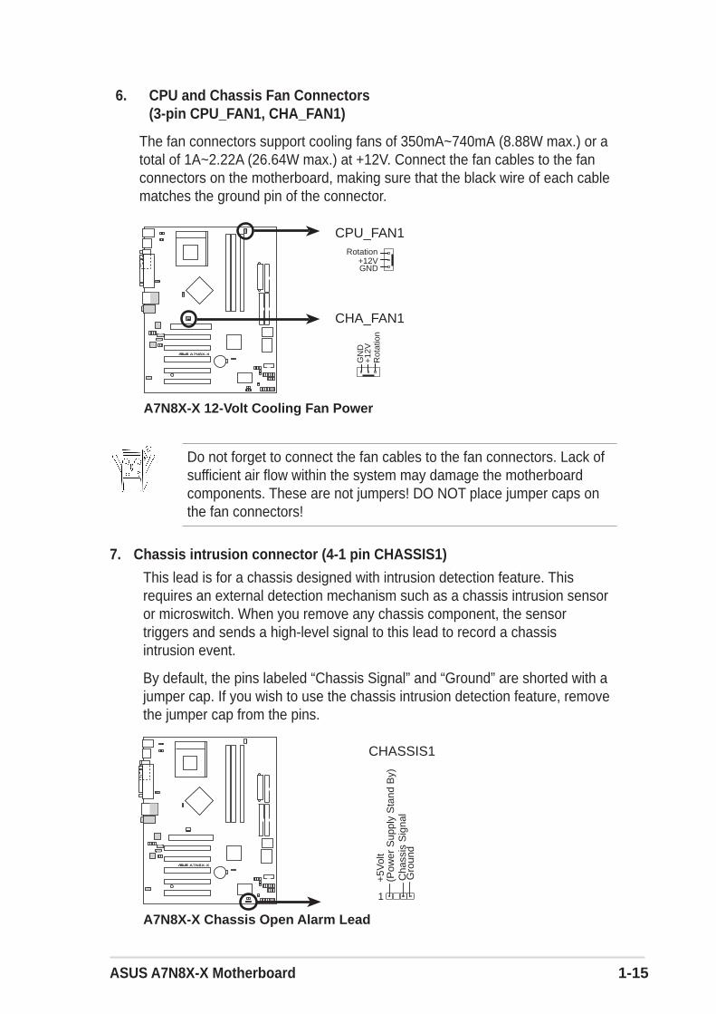
Do not forget to connect the fan cables to the fan connectors. Lack ofsufficient air flow within the system may damage the motherboardcomponents. These are not jumpers! DO NOT place jumper caps onthe fan connectors!
6. CPU and Chassis Fan Connectors(3-pin CPU_FAN1, CHA_FAN1)
The fan connectors support cooling fans of 350mA~740mA (8.88W max.) or atotal of 1A~2.22A (26.64W max.) at +12V. Connect the fan cables to the fanconnectors on the motherboard, making sure that the black wire of each cablematches the ground pin of the connector.
7. Chassis intrusion connector (4-1 pin CHASSIS1)
This lead is for a chassis designed with intrusion detection feature. Thisrequires an external detection mechanism such as a chassis intrusion sensoror microswitch. When you remove any chassis component, the sensortriggers and sends a high-level signal to this lead to record a chassisintrusion event.
By default, the pins labeled “Chassis Signal” and “Ground” are shorted with ajumper cap. If you wish to use the chassis intrusion detection feature, removethe jumper cap from the pins.
A7N8X-X®
A7N8X-X 12-Volt Cooling Fan Power
CHA_FAN1
GN
D
Rot
atio
n+
12V
CPU_FAN1
GND
Rotation+12V
A7N8X-X®
A7N8X-X Chassis Open Alarm Lead
CHASSIS1
+5V
olt
(Pow
er S
uppl
y S
tand
By)
Gro
und
Cha
ssis
Sig
nal
1

1-16 Chapter 1: Motherboard Information
9. Hard disk connector (2-pin IDELED1)
This 2-pin connector connects to the front panel HD LED and lights up onevery read/write activity of any of the disc drives connected to the primary orsecondary IDE slots.
8. Front panel audio connectors (10-1 pin FP_AUDIO1)
This is an interface for the Intel front panel audio cable that allow convenientconnection and control of audio devices.
10. OnBoard LED
The green Light Emitting Diode (LED) lights-ON if there is standby power andlights-OFF when the power is turned off.
A7N8X-X®
A7N8X-X Front Panel Audio Connector
FPAUDIO1
BLI
NE
_OU
T_L
MIC
2
Line
out
_R
Line
out
_L
BLI
NE
_OU
T_R
NC
MIC
PW
R+
5VA
AG
ND
A7N8X-X®
A7N8X-X IDE Activity LED
TIP: If the case-mounted LED does notlight, try reversing the 2-pin plug.
IDELED1
A7N8X-X®
A7N8X-X Onboard LED
PWR_LED1
ONStandbyPower
OFFPowered
Off
ASUS A7N8X-X Motherboard 1-17
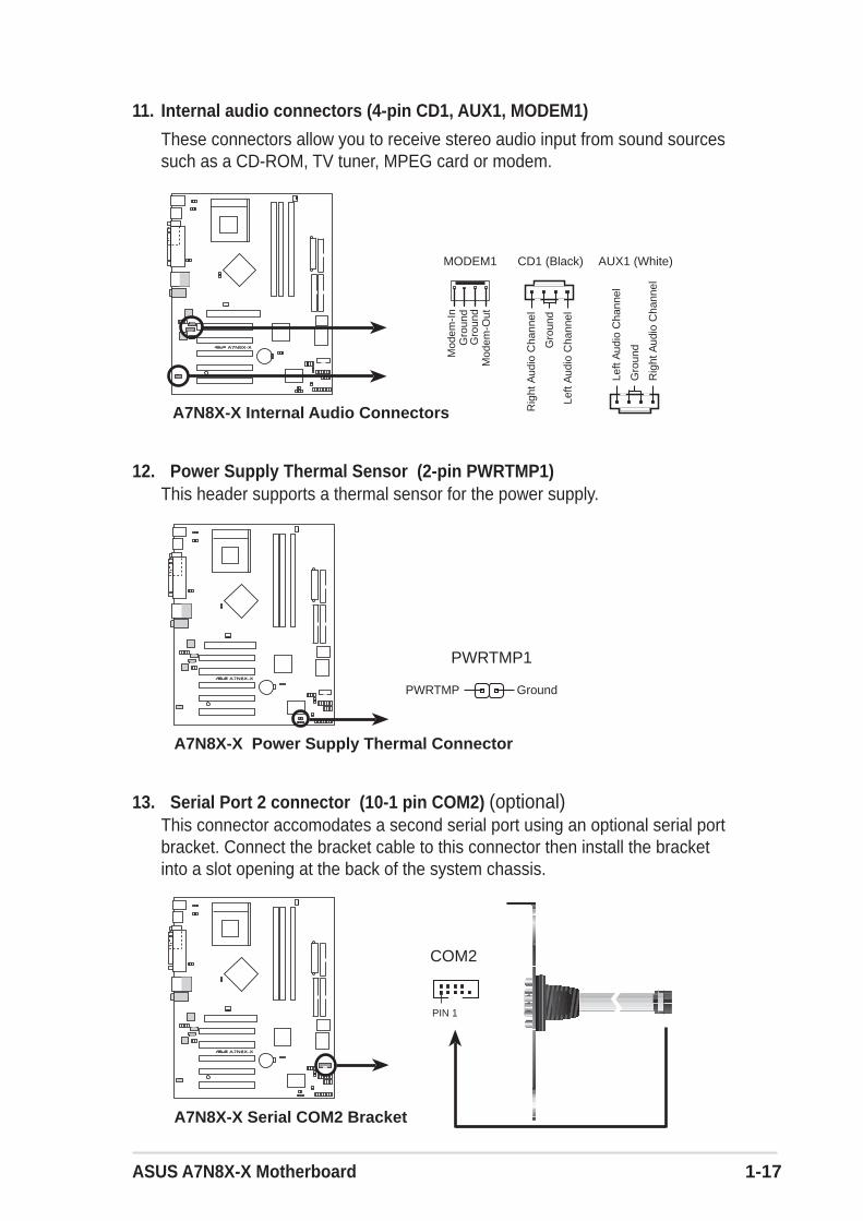
11. Internal audio connectors (4-pin CD1, AUX1, MODEM1)
These connectors allow you to receive stereo audio input from sound sourcessuch as a CD-ROM, TV tuner, MPEG card or modem.
A7N8X-X®
A7N8X-X Internal Audio Connectors
MODEM1 AUX1 (White)CD1 (Black)
Mod
em-I
n
Gro
und
Mod
em-O
ut
Gro
und
Rig
ht A
udio
Cha
nnel
Left
Aud
io C
hann
el
Gro
und
Rig
ht A
udio
Cha
nnel
Left
Aud
io C
hann
el
Gro
und
A7N8X-X®
A7N8X-X Power Supply Thermal Connector
PWRTMP1
GroundPWRTMP
12. Power Supply Thermal Sensor (2-pin PWRTMP1)This header supports a thermal sensor for the power supply.
A7N8X-X®
A7N8X-X Serial COM2 Bracket
PIN 1
COM2
13. Serial Port 2 connector (10-1 pin COM2) (optional)This connector accomodates a second serial port using an optional serial portbracket. Connect the bracket cable to this connector then install the bracketinto a slot opening at the back of the system chassis.

1-18 Chapter 1: Motherboard Information
15. Infrared Module connector (10-1 or 10-2 pin IR_CON1) (optional)
These connectors support an optional wireless transmitting and receivinginfrared module. The module mounts to a small opening on the system chassisthat support this feature. You must also configure the UART2 Use Asparameter in BIOS to set UART2 for use with IR.
Use the ten pins as shown in Back View and connect a ribbon cable from themodule to the motherboard SIR connector according to the pin definitions.
A7N8X-X®
A7N8X-X Infrared Connector
Standard Infrared (SIR)Front View Back View
+5VIRTX
IRRX(NC)GND
+5V
SB
NC
+5
VG
ND
CIR
RX
NC
GN
DIR
RX
IRT
X
CIRSIR
IR_CON1
A7N8X-X®
A7N8X-X Digital Audio Connector
SPDIF1
GN
D
+5V
SP
DIF
_IN
SP
DIF
_OU
T
GN
D
1
14. Digital Audio Connector (6 pin SPDIF1) (optional)This connector is for optional S/PDIF audio module that allows digital insteadof analog sound input and output.
When you input sound for S/PDIF IN, the LINE_OUT will output thesound. Mute LINE_OUT to impede sound output from S/PDIF IN.
ASUS A7N8X-X Motherboard 1-19
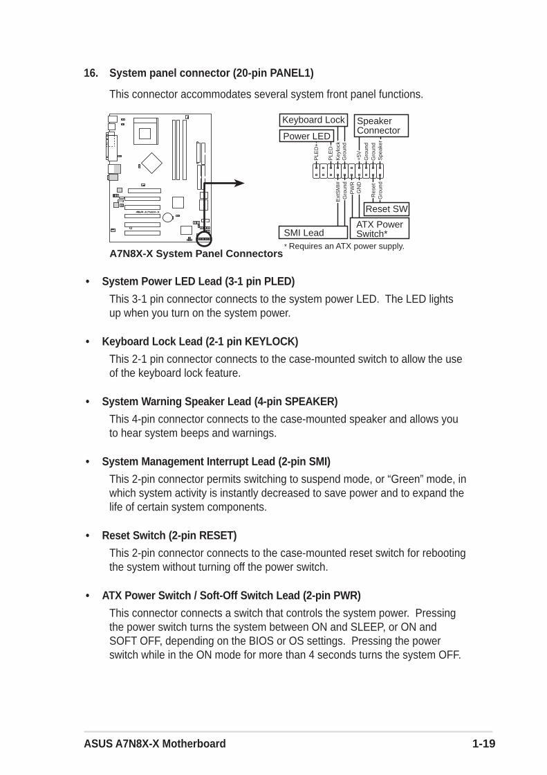
16. System panel connector (20-pin PANEL1)
This connector accommodates several system front panel functions.
• System Power LED Lead (3-1 pin PLED)
This 3-1 pin connector connects to the system power LED. The LED lightsup when you turn on the system power.
• Keyboard Lock Lead (2-1 pin KEYLOCK)
This 2-1 pin connector connects to the case-mounted switch to allow the useof the keyboard lock feature.
• System Warning Speaker Lead (4-pin SPEAKER)
This 4-pin connector connects to the case-mounted speaker and allows youto hear system beeps and warnings.
• System Management Interrupt Lead (2-pin SMI)
This 2-pin connector permits switching to suspend mode, or “Green” mode, inwhich system activity is instantly decreased to save power and to expand thelife of certain system components.
• Reset Switch (2-pin RESET)
This 2-pin connector connects to the case-mounted reset switch for rebootingthe system without turning off the power switch.
• ATX Power Switch / Soft-Off Switch Lead (2-pin PWR)
This connector connects a switch that controls the system power. Pressingthe power switch turns the system between ON and SLEEP, or ON andSOFT OFF, depending on the BIOS or OS settings. Pressing the powerswitch while in the ON mode for more than 4 seconds turns the system OFF.
A7N8X-X®
A7N8X-X System Panel Connectors* Requires an ATX power supply.
PLE
D-
Gro
und
PW
R
PLE
D+
Key
lock
+5V Spe
aker
SpeakerConnector
Power LED
Gro
und
Reset SW
SMI Lead
Ext
SM
I#
GN
D
Res
etG
roun
dG
roun
d
Gro
und
Keyboard Lock
ATX PowerSwitch*

1-20 Chapter 1: Motherboard Information

ASUS A7N8X-X Motherboard 2-1
This chapter gives information about the ASUSA7N8X-X Basic Input/Output System(BIOS).This chapter includes updating the BIOSusing the ASUS AFLASH BIOS that is bundledwith the support CD.
BIO
S In
form
atio
n
Chapter 2

2-2 Chapter 2: BIOS Setup
2.1 Managing and updating your BIOS
2.1.1 Using the computer system for the first time
It is recommended that you save a copy of the original motherboard BIOS along witha Flash Memory Writer utility (AWDFLASH.EXE) to a bootable floppy disk in caseyou need to reinstall the BIOS later. AWDFLASH.EXE is a Flash Memory Writerutility that updates the BIOS by uploading a new BIOS file to the programmable flashROM on the motherboard. This file works only in DOS mode. To determine the BIOSversion of your motherboard, check the last four numbers of the code displayed onthe upper left-hand corner of your screen during bootup. Larger numbers representa newer BIOS file.
1. Type FORMAT A:/S at the DOS prompt to create a bootable system disk. DO NOTcopy AUTOEXEC.BAT and CONFIG.SYS to the disk.
2. Type COPY D:\SOFTWARE\AWDFLASH\AWDFLASH.EXE A:\ (assuming D isyour CD-ROM drive) to copy AWDFLASH.EXE to the boot disk you created.
3. Reboot the computer from the floppy disk. To use AWDFLASH.EXE must beoperated from the ROOT directory. Therefore, copy the AWDFLASH.EXEprogram and the NEW BIOS file to the root directory on the hard disk drive;for example: type, “COPY A:\AWDFLASH.EXE C:\” and “COPYA:\BIOSNAME.BIN C:\.
If you encounter problems while updating the new BIOS, DO NOT turn off thesystem because this may cause boot problems. Just repeat the process, and ifthe problem persists, load the original BIOS file you saved to the boot disk, ortry to clear the CMOS memory (see section 1.7, Jumpers). If the Flash MemoryWriter utility is not able to successfully update a complete BIOS file, the systemmay not boot. If this happens, call the ASUS service center for support.
AWDFLASH works only in DOS mode. It does not work in the DOS promptwithin Windows, and does not work with certain memory drivers that may beloaded when you boot from the hard drive. It is recommended that you rebootusing a floppy disk in order to open DOS mode.

ASUS A7N8X-X Motherboard 2-3
2.1.2 Updating BIOS procedures
Updating BIOS via Built-in AwardBIOS Flash Utility
The Binary Input/Output System (BIOS) can be updated using the built-in FlashMemory Writer utility or using a bootable floppy disk with the executable FlashMemory Writer Utility (AWDFLASH.EXE). The following sub-sections explain thesteps in flashing your BIOS.
1. Download the latest BIOS file from the ASUS website (see ASUS contact info onPage viii). Save the copy to a floppy disk.
2. Reboot the computer.
3. To use AwardBIOS Flash Utility, press <Alt> + <F2> during POST to displaythe following screen.
Write down the BIOS file name on a piece of paper. You need to type the exactBIOS file name at the Award BIOS Flash Utility.
4. Insert the disk that contains the new BIOS file into the floppy drive. You willreceive the error message, “WARNING! Device not ready!” if you proceed tostep 5 without the disk in the drive.
5. Type the name of the new BIOS file, for example: “AW0702.BIN” then press <Enter>.The program asks if you want to save the previous BIOS. Select <Y> since it isadvisable to back-up the original BIOS in case you need to reprogram it.
The BIOS information in the above screen is for reference only. what you seeon your screen may not be exactly the same as shown.
Update the BIOS only if you have problems with the motherboard and you aresure that the new BIOS revision will solve your problems. Careless updatingmay create more problems !

2-4 Chapter 2: BIOS Setup
8. Type <Y> and Press <Enter> to flash the new Bios file. NOTE: Do not shutoff system power or unplug the supply during the flash process.
6. The program asks to save the previous BIOS to a separate file. Type a filename for the old bios and then press <Y>. The AWDFLASH program backs-up the file.
7. AWDFLASH proceeds to check the new BIOS file and asks the user toprogram (flash) the new BIOS file to the motherboard.

ASUS A7N8X-X Motherboard 2-5
9. The BIOS flashes and displays the results. Press <F1> to restart.
1. Boot from the floppy disk.
2. At the “A:\” prompt, type “C:\” and then press <Enter>.
3. At the “C:\” prompt, type “AWDFLASH /e BIOSFILE” and then <Enter>. Forexample: “AWDFLASH /e aw0702.bin” The AWDFLASH screen appears, andthe BIOS file appears in the space, “File Name to Program”.
4. Type the name of the new BIOS file, for example: “AW0702.BIN” then press <Enter>.The program asks if you want to save the previous BIOS. Select <Y> since it isadvisable to back-up the original BIOS in case you need to reprogram it.
5. Follow steps 6 to 9 in “2.1.2.1 Updating BIOS via Built-in Award BIOS FlashUtility.”
Updating BIOS via Bootable Floppy Disk

2-6 Chapter 2: BIOS Setup
2.2 BIOS Setup programThis motherboard supports a programmable FLASH ROM that you can update usingthe provided utility described in section “2.1 Managing and updating your BIOS.”
Use the BIOS Setup program when you are installing a motherboard, reconfiguringyour system, or prompted to “Run Setup”. This section explains how to configureyour system using this utility.
Even if you are not prompted to use the Setup program, you may want to change theconfiguration of your computer in the future. For example, you may want to enablethe security password feature or make changes to the power management settings.This requires you to reconfigure your system using the BIOS Setup program so thatthe computer can recognize these changes and record them in the CMOS RAM ofthe FLASH ROM.
The FLASH ROM on the motherboard stores the Setup utility. When you start up thecomputer, the system provides you with the opportunity to run this program. Press<Delete> during the Power-On Self Test (POST) to enter the Setup utility, otherwise,POST continues with its test routines.
If you wish to enter Setup after POST, restart the system by pressing <Ctrl> + <Alt>+ <Delete>, or by pressing the reset button on the system chassis. You can alsorestart by turning the system off and then back on. Do this last option only if the firsttwo failed.
The Setup program is designed to make it as easy to use as possible. It is a menu-driven program, which means you can scroll through the various sub-menus andmake your selections among the predetermined choices.
Because the BIOS software is constantly being updated, the following BIOSsetup screens and descriptions are for reference purposes only, and may notexactly match what you see on your screen.

ASUS A7N8X-X Motherboard 2-7
2.2.1 BIOS menu barThe top of the screen has a menu bar with the following selections:
MAIN Use this menu to make changes to the basic system configuration.
ADVANCED Use this menu to enable and make changes to the advancedfeatures, including BIOS, Chipset, Peripheral, Power and PnP/ PCIconfigurations.
SECURITY Use this menu to set the Supervisor and User passwords.
HARDWARE Monitor the status of vital components, including voltages and fanspeeds.
EXIT Use this menu to exit the current menu or to exit the Setupprogram.
To access the menu bar items, press the right or left arrow key on the keyboard untilthe desired item is highlighted.
2.2.2 Legend bar
At the bottom of the Setup screen is a legend bar. The keys in the legend bar allowyou to navigate through the various setup menus. The following table lists the keysfound in the legend bar with their corresponding functions.
Navigation Key(s) Function Description<F1> Displays the General Help screen<Esc> Jumps to the Exit menu or returns to the main menu from
a sub-menuLeft or Right arrow Selects the menu item to the left or rightUp or Down arrow Moves the highlight up or down between fieldsPage Down and – (minus) Scrolls backward through the values for the highlighted
fieldPage Up and + (plus) Scrolls forward through the values for the highlighted field<Enter> Brings up a selection menu for the highlighted field<F10> Saves changes and Exit
MONITOR

2-8 Chapter 2: BIOS Setup
General help
In addition to the Item Specific Help window, the BIOS setup program also providesa General Help screen. You may launch this screen from any menu by simply pressing<F1> or the <Alt> + <H> combination. The General Help screen lists the legend keysand their corresponding functions.
Saving changes and exiting the Setup program
See “4.7 Exit Menu” for detailed information on saving changes and exiting the setupprogram.
Scroll bar
When a scroll bar appears to the right of a help window, it indicates that there is moreinformation to be displayed that will not fit in the window. Use <PgUp> and <PgDn>or the up and down arrow keys to scroll through the entire help document. Press<Home> to display the first page, press <End> to go to the last page. To exit the helpwindow, press <Enter> or <Esc>.
Sub-menu
Note that a right pointer symbol (as shown on theleft) appears to the left of certain fields. This pointerindicates that you can display a sub-menu from thisfield. A sub-menu contains additional options for afield parameter. To display a sub-menu, move thehighlight to the field and press <Enter>. The sub-menu appears. Use the legend keys to navigateand enter values within each sub-menu as youwould within a menu. Use the <Esc> key to returnto the main menu. Take some time to familiarizeyourself with the legend keys and theircorresponding functions. Practice navigatingthrough the various menus and sub-menus. Whilemoving around through the Setup program, note that explanations appear in the ItemSpecific Help window located to the right of each menu. This window displays thehelp text for the currently highlighted field.

ASUS A7N8X-X Motherboard 2-9
System Date [mm/dd/yy]
Sets the system to the date that you specify (usually the current date). The format ismonth, day, year. Valid values for month, day, and year are Month: (1 to 12), Day: (1to 31), Year: (up to 2084). Use the <Tab> or <Shift> + <Tab> keys to move betweenthe month, day, and year fields.
System Time [hh:mm:ss]
Sets the system to the time that you specify (usually the current time). The format ishour, minute, second. Valid values for hour, minute and second are Hour: (00 to 23),Minute: (00 to 59), Second: (00 to 59). Use the <Tab> or <Shift> + <Tab> keys tomove between the hour, minute, and second fields.
Legacy Diskette A [1.44M, 3.5 in.]
Sets the type of floppy drive installed. Configuration options: [None] [360K, 5.25 in.][1.2M , 5.25 in.] [720K , 3.5 in.] [1.44M, 3.5 in.] [2.88M, 3.5 in.]
Halt On [All Errors]
This field sets the system to halt on errors according to the system functions specifiedin each option. Configuration options: [All Errors] [No Errors] [All, But Keyboard] [All, But Diskette] [All, But Disk/Key]
2.3 Main MenuWhen you enter the Setup program, the following screen appears.

2-10 Chapter 2: BIOS Setup
2.3.1 Primary Master/Slave
IDE HDD Auto-Detection [Press Enter]Press enter to automatically detect an IDE hard disk drive, if the hard drive is notalready detected. In cases of undetected HDDs, pressing enter will detect the HDDand then open access to both the IDE Primary Master and Access Mode fields.
IDE Primary Master/Slave [Auto]Select [Auto] to automatically detect an IDE hard disk drive. If automatic detection issuccessful, the setup BIOS automatically fills in the correct values for the remainingfields on this sub-menu. If automatic detection fails, this may be because the harddisk drive is too old or too new. If the hard disk was already formatted on a previoussystem, the setup BIOS may detect incorrect parameters. In these cases, select[Manual] to manually enter the IDE hard disk drive parameters. See Access Modebelow and refer to the next page for more details. If no drive is installed or if you areremoving a drive and not replacing it, select [None]. Configuration options: [None][Auto [Manual]
Access Mode [Auto]
The default [Auto] automatically detects an IDE hard disk drive. Select [CHS] incoordination with the [Manual] setting of the IDE Primary Master in order to enter theHard Disk Drive values manually.
Before attempting to configure a hard disk drive, make sure you have thecorrect configuration information supplied by the drive manufacturer. Incorrectsettings may cause the system to fail to recognize the installed hard disk.

ASUS A7N8X-X Motherboard 2-11
After making your selections on this sub-menu, press the <Esc> key to return to theMain menu. When the Main menu appears, the hard disk drive field displays the sizefor the hard disk drive that you configured.
[Manual] & [CHS] Settings
Manually enter the number of cylinders, heads and sectors per track for the drive.Refer to the drive documentation or on the drive label for this information.
Access Mode [Auto]Select the hard disk drive type in this field. When Logical Block Addressing (LBA) isenabled, the 28-bit addressing of the hard drive is used without regard for cylinders,heads, or sectors. Note that LBA Mode is necessary for drives with more than 504MBstorage capacity. Select [CHS] to make manual entries for configuring the fields below.Configuration options: [CHS] [LBA] [Large] [Auto]
CylindersThis field configures the number of cylinders. Refer to the drive documentation todetermine the correct value. To make changes to this field, set the IDE PrimaryMaster field to [Manual] and the Access Mode to [CHS].
HeadThis field configures the number of read/write heads. Refer to the drive documentationto determine the correct value. To make changes to this field, set the IDE PrimaryMaster field to [Manual] and the Access Mode to [CHS].
PrecompThis field displays the precompressed volumes on the hard disk, if any, in MB.
After entering the IDE hard disk drive information into BIOS, use a disk utility,such as FDISK, to partition and format new IDE hard disk drives. This isnecessary so that you can write or read data from the hard disk. Make sure toset the partition of the Primary IDE hard disk drives to active.

2-12 Chapter 2: BIOS Setup
2.3.2 Secondary Master/Slave
IDE HDD Auto-Detection [Press Enter]Press enter to automatically detect an IDE hard disk drive, if the hard drive is notalready detected. In cases of undetected HDDs, pressing enter will detect the HDDand then open access to both the IDE Primary Master and Access Mode fields.
IDE Secondary Master/Slave [Auto]
Select [Auto] to automatically detect an IDE hard disk drive. If automatic detection issuccessful, the setup BIOS automatically fills in the correct values for the remainingfields on this sub-menu. If automatic detection fails, this may be because the harddisk drive is too old or too new. If the hard disk was already formatted on a previoussystem, the setup BIOS may detect incorrect parameters. In these cases, select[Manual] to manually enter the IDE hard disk drive parameters. See Access Modebelow and refer to the next page for more details. If no drive is installed or if you areremoving a drive and not replacing it, select [None]. Configuration options: [None][Auto [Manual]
Access Mode [Auto]The default [Auto] automatically detects an IDE hard disk drive. Select [CHS] incoordination with the [Manual] setting of the IDE Primary Master in order to enter theHard Disk Drive values manually.
Landing ZoneThis field displays the drive’s maximum useable capacity as calculated by the BIOSbased on the drive information you entered.
SectorThis field configures the number of sectors per track. Refer to the drive documentationto determine the correct value. To make changes to this field, set the Type field to[User Type HDD] and the Translation Method field to [Manual].
Before attempting to configure a hard disk drive, make sure you have thecorrect configuration information supplied by the drive manufacturer. Incorrectsettings may cause the system to fail to recognize the installed hard disk.

ASUS A7N8X-X Motherboard 2-13
2.4 Advanced Menu
Advanced menu itemsThe Advanced menu accesses five important sub-menus:
Advanced BIOS Features
These fields set the functional properties of CPU caches, as well as boot devices,security and operational modes.
Advanced Chipset Features
These fields set chipset and CPU functions, including system and AGP caches, bootdevices, memory settings, voltages and frequencies.
Integrated Peripherals
These fields set the functional properties of the IDE channels, Master/Slave PIOs,USB, IEEE 1394, audio, network and modem support, as well as serial, game, midiand parallel addresses.
Power Management Setup
These fields set the functional properties of the ACPI, system power management,HDD power, network “wake-up” and “power-on” options.
PnP/PCI Configuration
These fields set the capacity of the BIOS to reset data configurations and toautomatically configure the system along with PCI/VGA properties. IRQ resourcesare accessed from this menu.
To access the menu bar items, press the up and down arrow keys and then press<enter> to view the desired menu.

2-14 Chapter 2: BIOS Setup
2.4.1 Advanced BIOS Features
Boot Virus Detection [Disabled]This field disables boot virus protection by default. Configuration options: [Enabled][Disabled]
CPU Level 1, Level 2 Cache [Enabled]These fields enables the CPU levels 1 and 2 cache by default.Configuration options: [Enabled] [Disabled]
Quick Power On Self Test [Enabled]This field enables the power on test. Configuration options: [Enabled] [Disabled]
First Boot Device [Floppy]This field sets the priority of the first boot device; by default, the system boots up onthe floppy diskette drive. Configuration options: [Floppy] [LS120] [HDD-0] [HDD-1][HDD-2] [HDD-3] [SCSI] [CDROM] [ZIP100] [LAN] [Disabled]
Second Boot Device [HDD-0]This field sets the priority of the second boot device; by default, the system boots upon the hard disk driver if the floppy drive is not present. Configuration options: [Floppy][LS120] [HDD-0] [HDD-1] [HDD-2] [HDD-3] [SCSI] [CDROM] [ZIP100] [LAN] [Disabled]
Third Boot Device [LS120]This field sets the priority of the third boot device; by default, the system boots up onthe LS120 if the flopyy and hard disk drive are not present. Configuration options:[Floppy] [LS120] [HDD-0] [HDD-1] [HDD-2] [HDD-3] [SCSI] [CDROM] [ZIP100] [LAN][Disabled]
Boot Other Device [Enabled]By default, this field enables the detection of other devices, aside from the first threepriority devices. Configuration options: [Enabled] [Disabled]
Boot-up Floppy Seek [Enabled]If enabled, this field speeds up the Power On Self Test (POST) routine by skippingand retesting several times. Configuration options: [Enabled] [Disabled]

ASUS A7N8X-X Motherboard 2-15
Boot-up NumLock Status [On]This field sets the capability of the NumLock light/key to display/activate the system.Configuration options: [On] [Off]
Gate A20 Option [Fast]This field sets the gate A20 rate. The default is [Fast].Configuration options: [Normal] [Fast]
Typematic Rate Setting [Disabled]This field enables or disable permission to change the rate of keystroke registrationand display. By default, the rate cannot be changed. Change to [Enabled] to makesettings in the nextt field. Configuration options: [Enabled] [Disabled]
APIC Mode [Enabled]This field enables or disables the APIC mode.Configuration options: [Enabled] [Disabled]
OS/2 Onboard Memory > 64MB [Disabled]This field enables or disables the 64MB onboard memory set for OS/2. Configurationoptions: [Disabled] [Enabled]
2.4.2 Advanced Chipset Features
(Scroll down to view all items on the menu.)
CPU External Frequency (MHz) [100MHz]This field sets the external frequency ratio of the CPU. The system normally auto-detects the frequency capability based on the type of CPU installed.The Front SideBus (FSB) is equal to 2 times this field value. Frequency ranges are adjustable inincrements of 1, 2, 3 and/or 5 MHz. Configuration options: [100 MHz]... [200 MHz] [204MHz] [207 MHz] [211 MHz] [300 MHz]

2-16 Chapter 2: BIOS Setup
CPU Frequency Multiple Setting [Auto]This field sets the frequency multiple between the CPU’s internal frequency (CPUspeed) and external frequency. Set this field in conjunction with CPU Frequency(MHz) to match the speed of the CPU.
CPU Frequency Multiple [5.0x]This field is available to unlocked processors only. For unlocked processors, thisfield sets the frequency multiple between the CPU’s internal frequency (CPU speed)and the external frequency.Configuration options: [5.0x] [5.5x]... ...[11.5] [12.0] [12.5x/13.0x]
System Performance [Optimal]This field permits change of mode for system performance. When set to [Optimal],the system uses the most stable settings. When you want to use overclocked settingsfor higher performance but with higher risk of instability, set to [Aggressive] and toallow full customization of performance options set to [User Defined]. Configurationoptions: [Optimal] [Aggressive] [User Defined]
CPU Interface [Optimal]This field sets the mode for CPU/FSB parameters usage. Select [Aggressive] if youwant to use overclocked CPU/FSB parameters. Otherwise, the default value is[Optimal] where it uses the most stable CPU/FSB parameters. Configuration options:[Optimal] [Aggressive]
Memory Frequency [By SPD]This field sets the type of memory frequency based on the type of DDR (Double DateRate) memory module installed. Resulting frequency can vary depending onpercentage setting which is multiplied by the FSB frqequency. Normally, the default,by SPD, permits autodetection. Configuration options: [By SPD] [50%] [60%] [66%][75%] [80%] [83%] [Sync] [120%] [125%] [133% [150%] [166%] [200%]
Resulting FrequencyThis field displays the resulting memory frequency.
Memory Timing [Optimal]This field permits change of memory timing mode for system performance. When setto [User Defined], the next four fields can be set manually. Set to [Aggressive] forhigher performance. Use default [Optimal] to use most stable settings. Configurationoptions: [Optimal] [Aggressive] [User Defined]
SDRAM Active Precharge Delay [7]Row-active delay.
SDRAM RAS to CAS Delay [1]RAS-to-CAS. This item controls the latency between the SDRAM Active command tothe SDRAM.

ASUS A7N8X-X Motherboard 2-17
SDRAM RAS Precharge Delay [1]Row-precharge delay.
SDRAM CAS Latency [2.5T]This field sets the override clock cycle for the latency time between the SDRAM readcommand and the moment that the data actually becomes available. Normally, thesystem determines the rate automatically by default.
FSB Spread Spectrum [Disabled]Configuration options: [Disabled] [0.50%] [1.00%]
AGP Spread Spectrum [Disabled]Configuration options: [Disabled] [0.50%] [1.00%]
CPU Vcore Setting [Auto]This field determines if the CPU Vcore is automatically scaled or set manually by theuser. The default value is [Auto], therefore, the CPU vcore voltage is set for maximumperformance without stressing the CPU. Configuration options: [Auto] [Menu]
CPU Vcore [1.850V]When the CPU VCore Setting parameter is set to [Manual], this field permits selectionof specific CPU core voltages. This field is not accessible if the above CPU VCoreSetting parameter is set to [Auto].Configuration options: [1.100V] [1.125V] ... [1.825] [1.850V]
Graphics Aperture Size [64M]This field sets the size of mapped memory ( in megabytes ) for AGP graphic data.Configuration options: [32M] [64M] [128M] [256M] [512M]
AGP Frequency [Auto]This field sets the frequency of the AGP controller. The default, [Auto], permitsautomatic selection of optimal AGP frequencies. Configuration options: [50, 66, 67,68, 69, 70, 71, 72, 73, 74, 75, 76, 77, 78, 79, 80, 81, 82, 83, 84, 85, 86, 87, 90, 93, 95, 97,100MHz]
System BIOS Cacheable [Disabled]This field establishes whether or not the BIOS is cacheable. Disabled by default.Configuration options: [Enabled] [Disabled]
The configuration option range varies from CPU’s with different clock speed.
2-18 Chapter 2: BIOS Setup
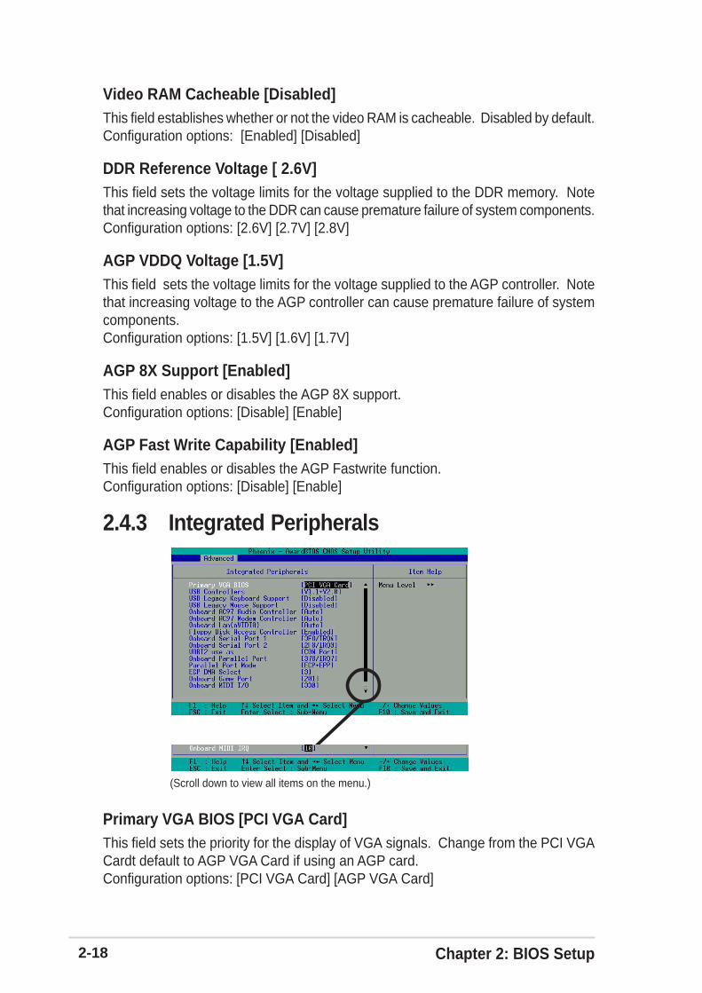
2.4.3 Integrated Peripherals
(Scroll down to view all items on the menu.)
Video RAM Cacheable [Disabled]This field establishes whether or not the video RAM is cacheable. Disabled by default.Configuration options: [Enabled] [Disabled]
DDR Reference Voltage [ 2.6V]This field sets the voltage limits for the voltage supplied to the DDR memory. Notethat increasing voltage to the DDR can cause premature failure of system components.Configuration options: [2.6V] [2.7V] [2.8V]
AGP VDDQ Voltage [1.5V]This field sets the voltage limits for the voltage supplied to the AGP controller. Notethat increasing voltage to the AGP controller can cause premature failure of systemcomponents.Configuration options: [1.5V] [1.6V] [1.7V]
AGP 8X Support [Enabled]This field enables or disables the AGP 8X support.Configuration options: [Disable] [Enable]
AGP Fast Write Capability [Enabled]This field enables or disables the AGP Fastwrite function.Configuration options: [Disable] [Enable]
Primary VGA BIOS [PCI VGA Card]This field sets the priority for the display of VGA signals. Change from the PCI VGACardt default to AGP VGA Card if using an AGP card.Configuration options: [PCI VGA Card] [AGP VGA Card]

ASUS A7N8X-X Motherboard 2-19
USB Controllers [V1.1+V2.0]This field sets the protocols for OnChip processing of USB outputs. The defaultaccomodates USB protocols 1.0 and 2.0.Configuration options: [Disabled] [V1.1 +V2.0] [V1.1]
USB Legacy Keyboard Support [Disabled]This field sets support for USB keyboards. The USB keyboard is disabled by default.Enable this field to use a USB keyboard. Configuration options: [Enabled] [Disabled]
USB Legacy Mouse Support [Disabled]This field sets support for USB keyboards. The USB keyboard is disabled by default.Enable this field to use a USB keyboard. Configuration options: [Enabled] [Disabled]
Onboard AC97 Audio Controller [Auto]This field permits auto selection of AC97 audio codec processing by default.Configuration options: [Auto] [Disabled]
Onboard AC97 Modem Controller [Auto]This field permits auto selection of AC97 modem support by default.Configuration options: [Auto] [Disabled]
Onboard Lan (nVIDIA) [Auto]This field permits auto selection of MAC Lan (nVidia) support by default.Configuration options: [Auto] [Disabled]
Floppy Disk Access Controller [Enabled]This field enables the FDA Controller by default.Configuration options: [Enabled] [Disabled]
Onboard Serial Port 1 [3F8/IRQ4]These fields set the addresses for onboard serial port 1. Serial Port 1 and Serial Port2 must have different addresses. Configuration options: [Disabled] [3F8/IRQ4] [2F8/IRQ3] [3E8/IRQ4] [2E8/IRQ3] [Auto]
Onboard Serial Port 2 [2F8/IRQ3]These fields set the addresses for onboard serial port 2. Serial Port 1 and Serial Port2 must have different addresses. Configuration options: [Disabled] [3F8/IRQ4] [2F8/IRQ3] [3E8/IRQ4] [2E8/IRQ3] [Auto]
UART use as [COM Port]This field selects the device assignment for UART2 mode. The default is [COMPort]. Select [IR] to activate the next field, “UR2 Duplex Mode”.Configuration options: [IR] [COM Port]
2-20 Chapter 2: BIOS Setup
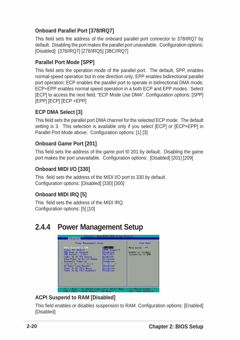
2.4.4 Power Management Setup
Onboard Parallel Port [378/IRQ7]This field sets the address of the onboard parallel port connector to 378/IRQ7 bydefault. Disabling the port makes the parallel port unavailable. Configuration options:[Disabled] [378/IRQ7] [278/IRQ5] [3BC/IRQ7]
Parallel Port Mode [SPP]This field sets the operation mode of the parallel port. The default, SPP, enablesnormal-speed operation but in one direction only; EPP enables bidirectional parallelport operation; ECP enables the parallel port to operate in bidirectional DMA mode;ECP+EPP enables normal speed operation in a both ECP and EPP modes. Select[ECP] to access the next field, “ECP Mode Use DMA”. Configuration options: [SPP][EPP] [ECP] [ECP +EPP]
ECP DMA Select [3]This field sets the parallel port DMA channel for the selected ECP mode. The defaultsetting is 3. This selection is available only if you select [ECP] or [ECP+EPP] inParallel Port Mode above. Configuration options: [1] [3]
Onboard Game Port [201]This field sets the address of the game port t0 201 by default. Disabling the gameport makes the port unavailable. Configuration options: [Disabled] [201] [209]
Onboard MIDI I/O [330]This field sets the address of the MIDI I/O port to 330 by default.Configuration options: [Disabled] [330] [300]
Onboard MIDI IRQ [5]This field sets the address of the MIDI IRQ.Configuration options: [5] [10]
ACPI Suspend to RAM [Disabled]This field enables or disables suspension to RAM. Configuration options: [Enabled][Disabled]

ASUS A7N8X-X Motherboard 2-21
Video Off Method [DPMS Support]This field defines “video off” features. The DPMS support option (Display PowerManagement System) permits the BIOS to control the video display card if it supportsthe DPMS feature. Blank Screen option blanks the screen; use blank screen formonitors without power management or “green” features. [V/H SYNC+Blank] blanksthe screen and turns off vertical and horizontal scanning. Configuration options: [BlankScreen] [V/H SYNC+Blank] [DPMS Support]
HDD Down In Suspend [Disabled]This field sets whether or not the HDD is automatically shut down in suspend mode.The default disables power to the HDD in suspend mode. Configuration options:[Enabled] [Disabled]
PWR button < 4 Secs [Suspend]This field sets the delay after which the system powers off after depressing the externalcase-mounted power button. The default setting powers off the system instantly.Configuration options: [Soft-Off] [Suspend]
Power Up on PCI Device [Enabled]This field enables Wake-On-LAN from soft-off mode. The default disables this option.Configuration options: [Enabled] [Disabled]
Wake-Power Up On Ext. Modem [Disabled]This field allows either settings of [Enabled] or [Disabled] for powering up the computerwhen the external modem receives a call while teh computer is in Soft-off mode.Configuration options: [Enabled] [Disabled]
Automatic Power Up [Disabled]This field sets to enable or disable the automatic power up.When [Enabled] the Time(hh:mm:ss) of Alarm field is enabled for input.Configuration options: [Enabled] [Disabled]
Time (hh:mm:ss) of Alarm 0:00:00This field sets the time for automatic power up. Enter the hour, minute and secondbased on the 24 hour clock. The Automatic Power Up field must be enabled to usethis feature.
AC Power Loss Restart [Disabled]This allows you to set whether or not to reboot the system after power interruptions.[Disabled] leaves your system off while [Enabled] reboots the system. [Previous State]sets the system back to the state it was before the power interruption.Configuration options: [Disabled] [Enabled] [Previous State]

2-22 Chapter 2: BIOS Setup
Resources Controlled By [Auto(ESCD)]This field sets control over the IRQ resources by the automatic (ESCD) system ormanual assignment of IRQ channels. The default enables automatic (ESCD) control.Configuration options: [Auto(ESCD)] [Manual].
PCI/VGA Palette Snoop [Disabled]This field enables the PCI/VGA palette snoop. This feature is disabled by default.Configuration options: [Enabled] [Disabled]
2.4.5 PnP / PCI Configurations
Power On By PS/2 Mouse [Disabled]When set to [Enabled], this parameter allows you to use the PS/2 mouse to turn onthe system. This feature requires an ATX power supply that provides at least 1A onthe +5VSB lead. Configuration options: [Disabled] [Enabled]
Power On By PS/2 Keyboard [Disabled]This parameter allows you to use specific keys on the keyboard to turn on thesystem. This feature requires an ATX power supply that provides at least 1A on the+5VSB lead. Configuration options: [Disabled] [Any KEY] [Power Key]

ASUS A7N8X-X Motherboard 2-23
2.5 Security MenuThe BIOS Setup program permits two different passwords to control access to theBIOS during system startup: a Supervisor password and a User password.Passwords are not case sensitive, meaning, passwords can be typed in eitheruppercase or lowercase letters. The table below describes the authority level whensetting Supervisor or User Password.
TABLE 4.5.2 User Set Password only
Security Option Supervisor Password User Password
A password is required forbooting and entering intothe CMOS setup and allitems can be modified.
A password is required toenter into the CMOS setupand all items can bemodified.
System
Setup
None
None
TABLE 2.5.1 Supervisor/User Set Password
Security Option Supervisor Password User Password
System A password is required forbooting and entering into theCMOS setup and all items canbe modified.
A password is required forbooting and entering intothe CMOS setup and only“Date” and “Time” could bemodified. All other items inthe CMOS are displayedonly.
A password is required toenter into the CMOS anditems can be modified.
A password is required toenter into the CMOS andonly “Date” and “Time”could be modified. All otheritems in the CMOS aredisplayed only.
Setup

2-24 Chapter 2: BIOS Setup
2.6 Hardware Monitor MenuThe Harware Monitor menu displays all vital system statistics.
Set Supervisor Password / Set User PasswordTo set a password, highlight the appropriate field and press <Enter>. Type in apassword then press <Enter>. You can type up to eight alphanumeric characters;symbols and other characters are not useable. To confirm the password, type thepassword again and press <Enter>. The password is now set to [Enabled]. Thispassword permits full access to the BIOS Setup menus. To clear the password,highlight this field and press <Enter>. The same dialog box as above appears. Press<Enter>. The password is set to [Disabled].
Security Option [Setup]This field sets the security options. The default enables the setup option for security.Configuration options: [Setup] [System]
Forgot the password?If you forget a password, you can clear it by erasing the CMOS Real Time Clock (RTC)RAM. The RAM data containing the password information is powered by the onboard buttoncell battery.
NOTE: See section “1.9�Jumpers” for more information about how to erase the RTC RAM.

ASUS A7N8X-X Motherboard 2-25
MB, CPU Temperature [xx C / xx F]The onboard hardware monitor automatically detects the MB (motherboard) andCPU temperatures.
VCORE Voltage, +3.3V Voltage, +5V Voltage, +12V VoltageThe onboard hardware monitor automatically detects the voltage output through thevoltage regulators.
CPU Fan Speed xxxx RPM or 0 RPMCHASSIS Fan Speed xxxx RPM or 0 RPMPOWER Fan Speed xxxx RPM or 0 RPMThe onboard hardware monitor automatically detects the CPU, power and chassisfan speeds and displays the fan speeds in revolutions per minute (RPM). If any ofthe fans is not connected to the fan connectors on the motherboard, the specificfield will show N/A.
Q-Fan Control [Disabled]This field allows you to enable or disable the ASUS Q-Fan feature that smartlyadjusts the fan speeds for more efficient system operation. When this field is set to[Enabled], set the appropriate Fan Speed Ratio and Speed Up/DownResponse Time. Configuration options: [Disabled] [Enabled]
Fan Speed Ratio [10/15]This item allows you to select the appropriate fan speed ratio for the system. Thedefault [10/15] is the minimum fan speed ratio. Select a higher ratio if you installedadditional devices and the system requires more ventilation. This item is requiredto be set when the Q-Fan Control field is [Enabled]. Configuration options: [10/15][11/15] [12/15] [13/15] [14/15] [Full Speed].
Speed Up/Down Response Time [4 Sec/8 Sec]This item indicates the time period before the fan speeds adjust to the vale set inthe Fan Speed Ratio field. This item is required to be set when the Q-FanControl field is [Enabled]. Configuration options: [1 Sec/2 Sec] [2 Sec/4 Sec] [3Sec/6 Sec] [4 Sec/8 Sec]
2-26 Chapter 2: BIOS Setup
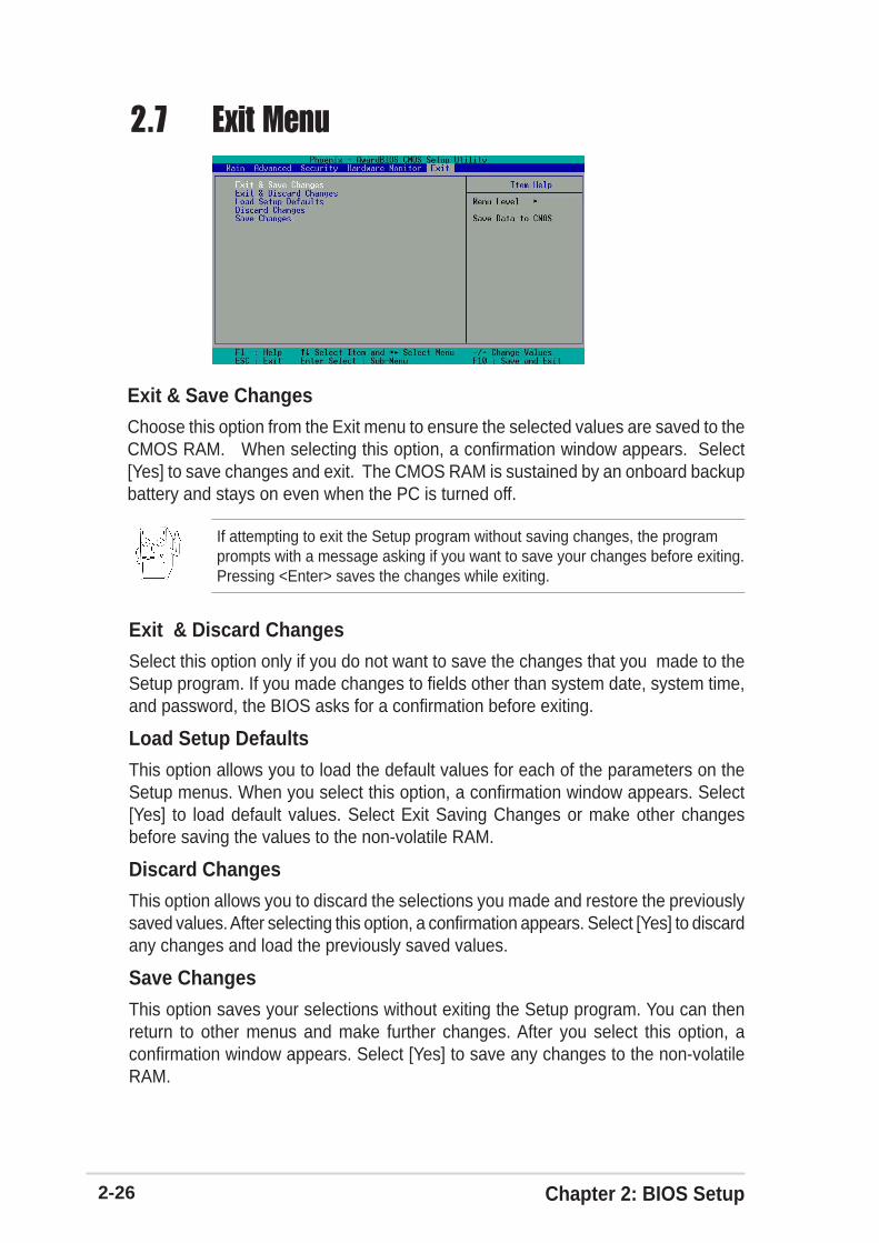
2.7 Exit Menu
Exit & Save ChangesChoose this option from the Exit menu to ensure the selected values are saved to theCMOS RAM. When selecting this option, a confirmation window appears. Select[Yes] to save changes and exit. The CMOS RAM is sustained by an onboard backupbattery and stays on even when the PC is turned off.
Exit & Discard ChangesSelect this option only if you do not want to save the changes that you made to theSetup program. If you made changes to fields other than system date, system time,and password, the BIOS asks for a confirmation before exiting.
Load Setup Defaults
This option allows you to load the default values for each of the parameters on theSetup menus. When you select this option, a confirmation window appears. Select[Yes] to load default values. Select Exit Saving Changes or make other changesbefore saving the values to the non-volatile RAM.
Discard ChangesThis option allows you to discard the selections you made and restore the previouslysaved values. After selecting this option, a confirmation appears. Select [Yes] to discardany changes and load the previously saved values.
Save Changes
This option saves your selections without exiting the Setup program. You can thenreturn to other menus and make further changes. After you select this option, aconfirmation window appears. Select [Yes] to save any changes to the non-volatileRAM.
If attempting to exit the Setup program without saving changes, the programprompts with a message asking if you want to save your changes before exiting.Pressing <Enter> saves the changes while exiting.

3-1ASUS A7N8X-X Motherboard
This chapter helps you power up your systemand install drivers and utilities that came with thesupport CD.
Sta
rtin
g U
p
Chapter 3

3-2 Chapter 3: Starting-Up
The contents of the support CD are subject to change at any timewithout notice. Visit the ASUS website for updates.
Because motherboard settings and hardware options vary, use thesetup procedures presented in this chapter for general reference only.Refer to your OS documentation for more information.
3.1 Install an operating systemThis motherboard supports Windows 98SE/ME/NT/2000/XP operatingsystem (OS). Always install the latest OS version and correspondingupdates so you can maximize the features of your hardware.
3.2 Support CD informationThe support CD that came with the motherboard contains useful softwareand several utility drivers that enhance the motherboard features.
3.2.1 Running the support CDTo begin using the support CD, simply insert the CD into your CD-ROMdrive. The CD automatically displays the Drivers menu if Autorun isenabled in your computer.
If Autorun is NOT enabled in your computer, browse the contents ofthe support CD to locate the file ASSETUP.EXE from the BIN folder.Double-click the ASSETUP.EXE to run the CD.
Click an icon to displaymore information
Click an item to install

ASUS A7N8X-X Motherboard 3-3
3.2.2 Drivers menuThe drivers menu shows the available device drivers if the system detectsinstalled devices. Install the necessary drivers to activate the devices.
NVIDIA nForce DriverThis item installs the NVIDIA nForce set of drivers.
QFE DriversClick this item to load the installation wizard and install the Win98 QFE drivers.
USB 2.0 DriverThis item installs the Universal Serial Bus 2.0 (USB 2.0) driver.
Some menu items appear only to specific operating system versions.
3.2.3 Utilities menuThe Utilities menu shows the applications and other software that themotherboard supports.
ASUS PC ProbeInstall utility that can monitor Fan, Speed, Voltage, and CPU temperature.
ASUS UpdateInstalls utility to download and update motherboard BIOS & drivers.
Microsoft DirectX DriverThis item installs the Microsoft DirectX driver.

3-4 Chapter 3: Starting-Up
Anti-virus UtilityThe anti-virus application scans, identifies, and removes computer viruses. Viewthe online help for detailed information.
ADOBE Acrobat Reader V5.0This installs software for viewing files in Portable Document Format (PDF).
ASUS Screen SaverThis item installs the ASUS screen saver.
3.2.4 ASUS Contact InformationClicking the ASUS Contact Information tab displays as stated. You mayalso find this information on page viii of this user guide.