Embed Size (px)
Citation preview
August 2013
A6 to Manchester Airport
Relief Road
B003 –Mill Lane Accommodation Bridge
Preliminary Design Report
Report No. 1007/704/151
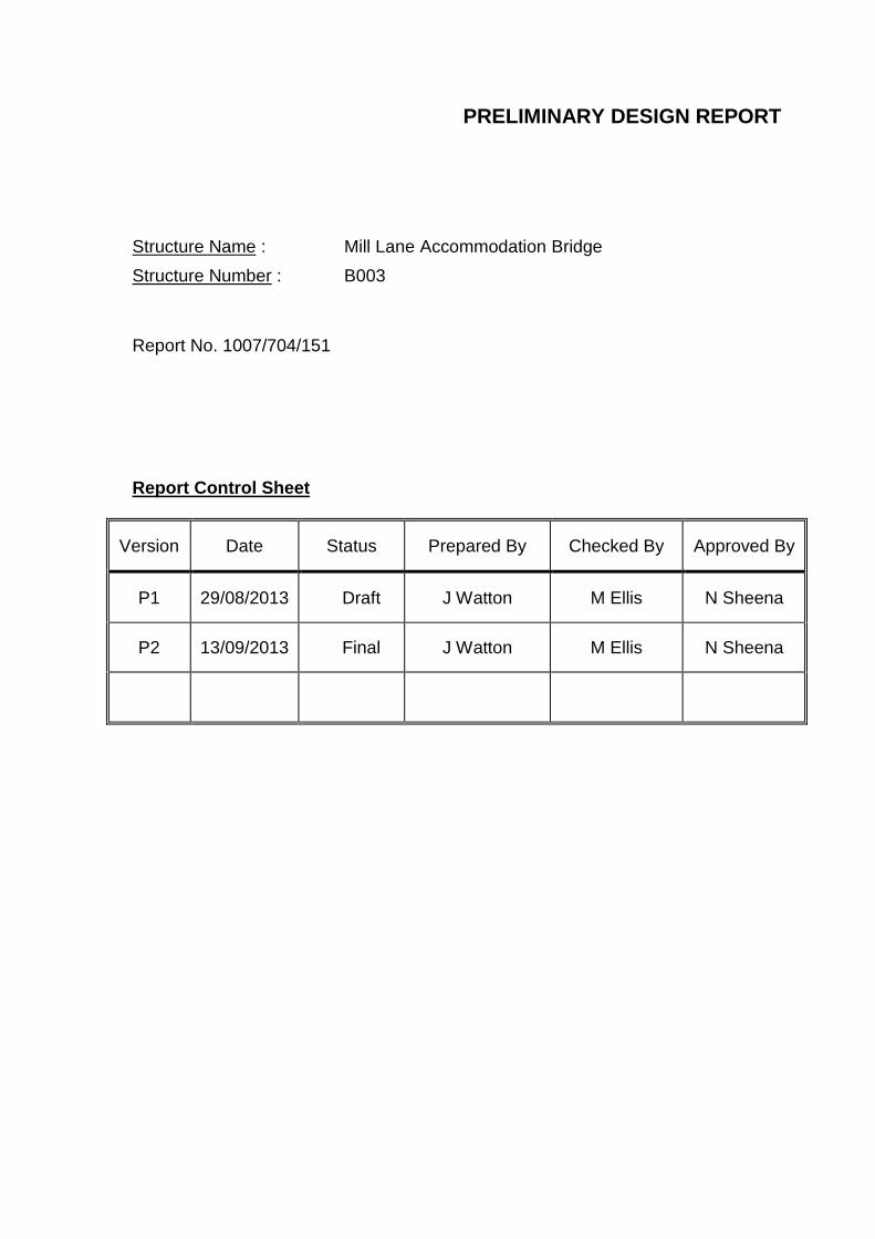
PRELIMINARY DESIGN REPORT
Structure Name : Mill Lane Accommodation Bridge
Structure Number : B003
Report No. 1007/704/151 Report Control Sheet
Version Date Status Prepared By Checked By Approved By
P1 29/08/2013 Draft J Watton M Ellis N Sheena
P2 13/09/2013 Final J Watton M Ellis N Sheena
B003- Mill Lane Accommodation Bridge Stockport Metropolitan Borough Council Preliminary Design Report
Table of Contents
1. Description of Site ............................................................................................... 4
2. Highway Details .................................................................................................. 4
3. Proposed Structure ............................................................................................. 4
4. Span Arrangements ............................................................................................ 4
5. Headroom and Clearances ................................................................................. 4
6. Road Restraint System (Bridge Parapets) .......................................................... 5
7. Preferred Structural Options ............................................................................... 5
7.1 Superstructure Options ................................................................................... 5
7.2 Substructure Options ...................................................................................... 6
8. Geotechnical Information .................................................................................... 6
9. Appearance......................................................................................................... 7
Appendix A: Location Plans Appendix B: Proposed General Arrangement Drawing 3D Model Appendix C: Ground Investigation Information
B003- Mill Lane Accommodation Bridge Stockport Metropolitan Borough Council Preliminary Design Report
1. Description of Site
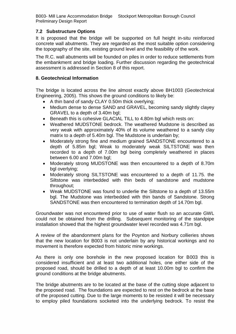
The Mill Lane Accommodation Bridge is part of the A6 to Manchester Airport Relief Road (A6MARR) and is proposed to give farmers, pedestrians, cyclists and equestrian access across the relief road. The bridge is to be located approximately 100m and 140m south-west of Buxton railway and Buxton Road respectively at route chainage 8670m approximately.
There are a large number of residential properties on Mill Lane to the north of the site and several on Old Mill Lane to the west of the proposed bridge crossing. The immediate surrounding area of the proposed bridge is open farm land. An aerial location plan at 1:1250 scale is included in Appendix A.
2. Highway Details
Over Structure – Mill Lane Accommodation Bridge – 3.0m wide single carriageway with two verges and string courses. (2 x 0.5m verges + 3.0m carriageway + 2 x 0.5m string courses)
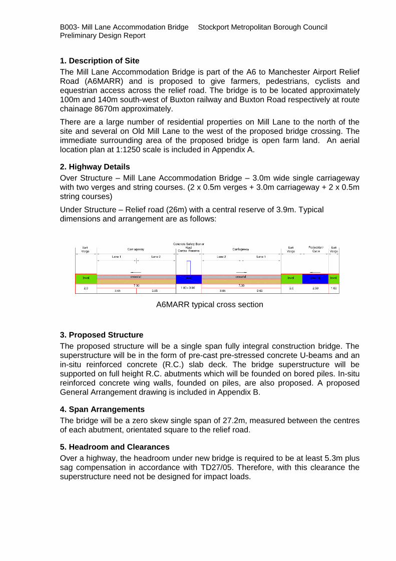
Under Structure – Relief road (26m) with a central reserve of 3.9m. Typical dimensions and arrangement are as follows:
A6MARR typical cross section
3. Proposed Structure
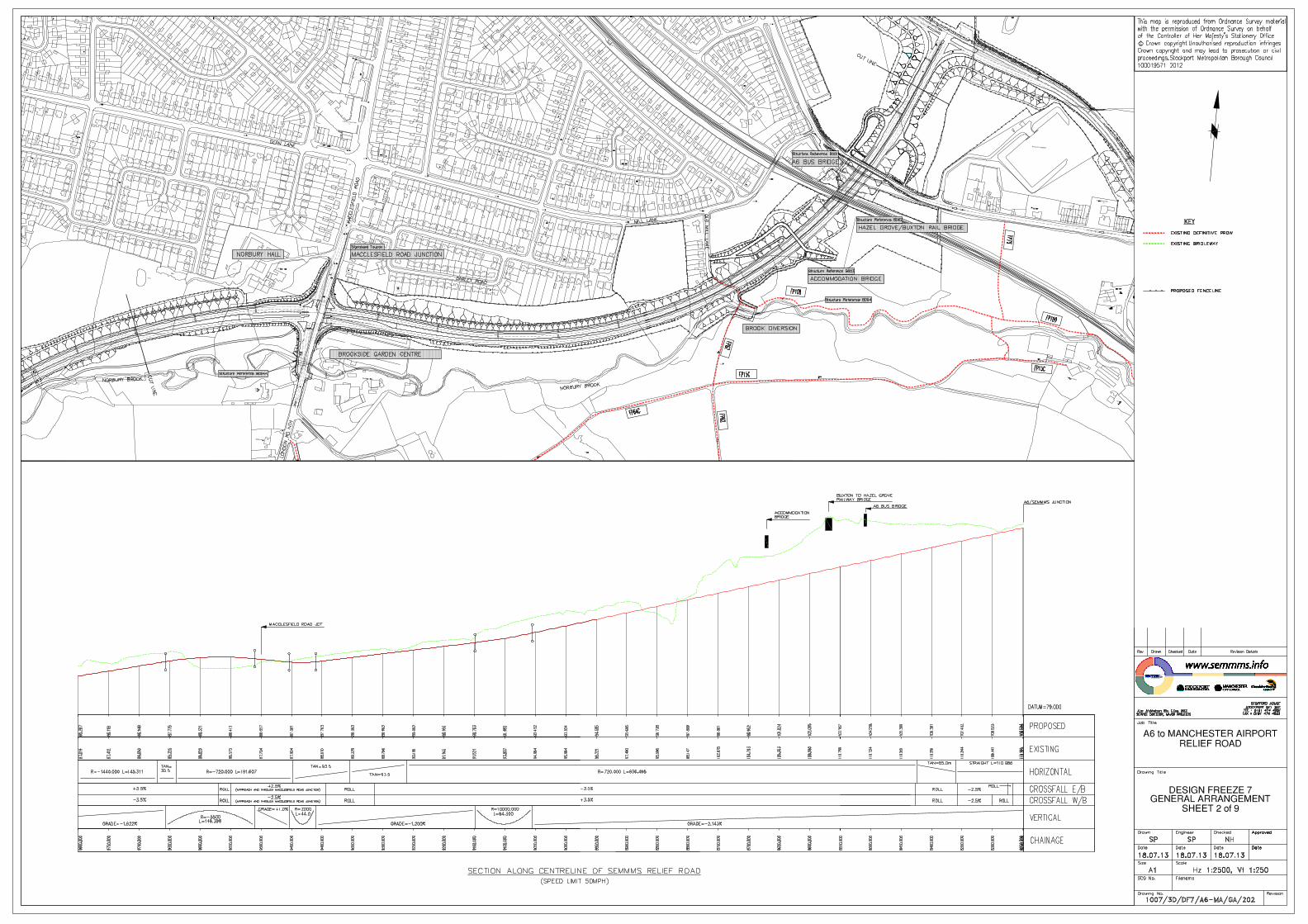
The proposed structure will be a single span fully integral construction bridge. The superstructure will be in the form of pre-cast pre-stressed concrete U-beams and an in-situ reinforced concrete (R.C.) slab deck. The bridge superstructure will be supported on full height R.C. abutments which will be founded on bored piles. In-situ reinforced concrete wing walls, founded on piles, are also proposed. A proposed General Arrangement drawing is included in Appendix B.
4. Span Arrangements
The bridge will be a zero skew single span of 27.2m, measured between the centres of each abutment, orientated square to the relief road.
5. Headroom and Clearances
Over a highway, the headroom under new bridge is required to be at least 5.3m plus sag compensation in accordance with TD27/05. Therefore, with this clearance the superstructure need not be designed for impact loads.

B003- Mill Lane Accommodation Bridge Stockport Metropolitan Borough Council Preliminary Design Report
6. Road Restraint System (Bridge Parapets)
The bridge parapets will be type N2 steel parapet with galvanised steel mesh infill in accordance with TD 19/06 and the Road Restraints Risk Assessment Process (RRRAP). Working width class is to be no greater than W4 and will be decided in the final phase of the design. Parapet height is to be 1.8m above finished road level at both verges to accommodate equestrian access and a 600mm high solid infill panel should be provided at the bottom of the parapet to obstruct an animal’s view of the road below.
7. Preferred Structural Options
7.1 Superstructure Options
It is proposed that the bridge will be a single span, fully integral pre-cast pre-stressed concrete U-beams supporting an in-situ reinforced concrete slab deck. Refer to drawing 1007/3D/DF7/A6-MA/B003/701 and the 3D Model in Appendix B for further details.
For a span range up to 30m, fully integral construction is normally considered a cost effective option. Elimination of movement joints removes a major cause of maintenance problems from penetration of dirt, water and de-icing salts, which corrode substructures and bearings.
The advantages for using pre-cast concrete beam construction are as follows:
Low capital & whole-life cost
Fast and efficient build
Factory quality with engineered tolerances
Low maintenance
The beams can be lifted individually
Permanent formwork provides self-supporting system during construction and eliminates falsework
Reduces site works which are weather dependent
Disadvantages:
Precast concrete beams are usually heavier than comparable steel beams. As a result larger cranes might be required to lift the precast concrete beams
Heavier superstructure mentioned above might lead to larger foundation sizes
Delivery times are dependent on a specialist supplier
B003- Mill Lane Accommodation Bridge Stockport Metropolitan Borough Council Preliminary Design Report
7.2 Substructure Options
It is proposed that the bridge will be supported on full height in-situ reinforced concrete wall abutments. They are regarded as the most suitable option considering the topography of the site, existing ground level and the feasibility of the work.
The R.C. wall abutments will be founded on piles in order to reduce settlements from the embankment and bridge loading. Further discussion regarding the geotechnical assessment is addressed in Section 8 of this report.
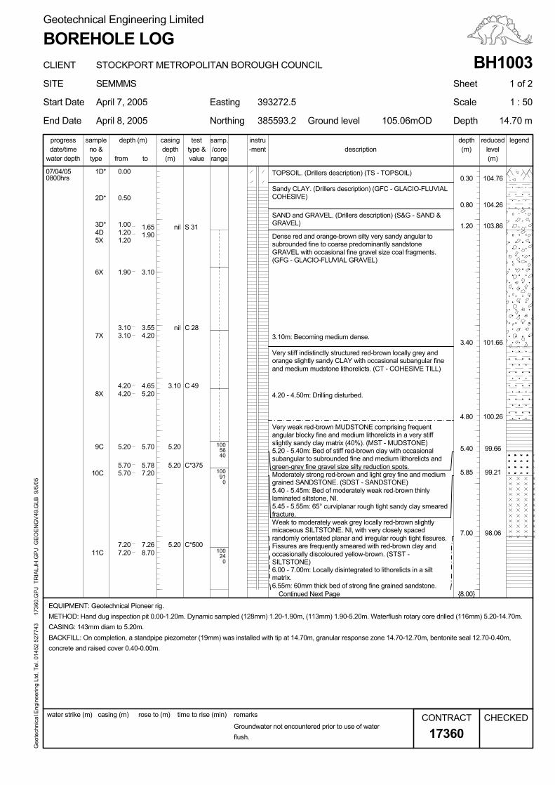
8. Geotechnical Information
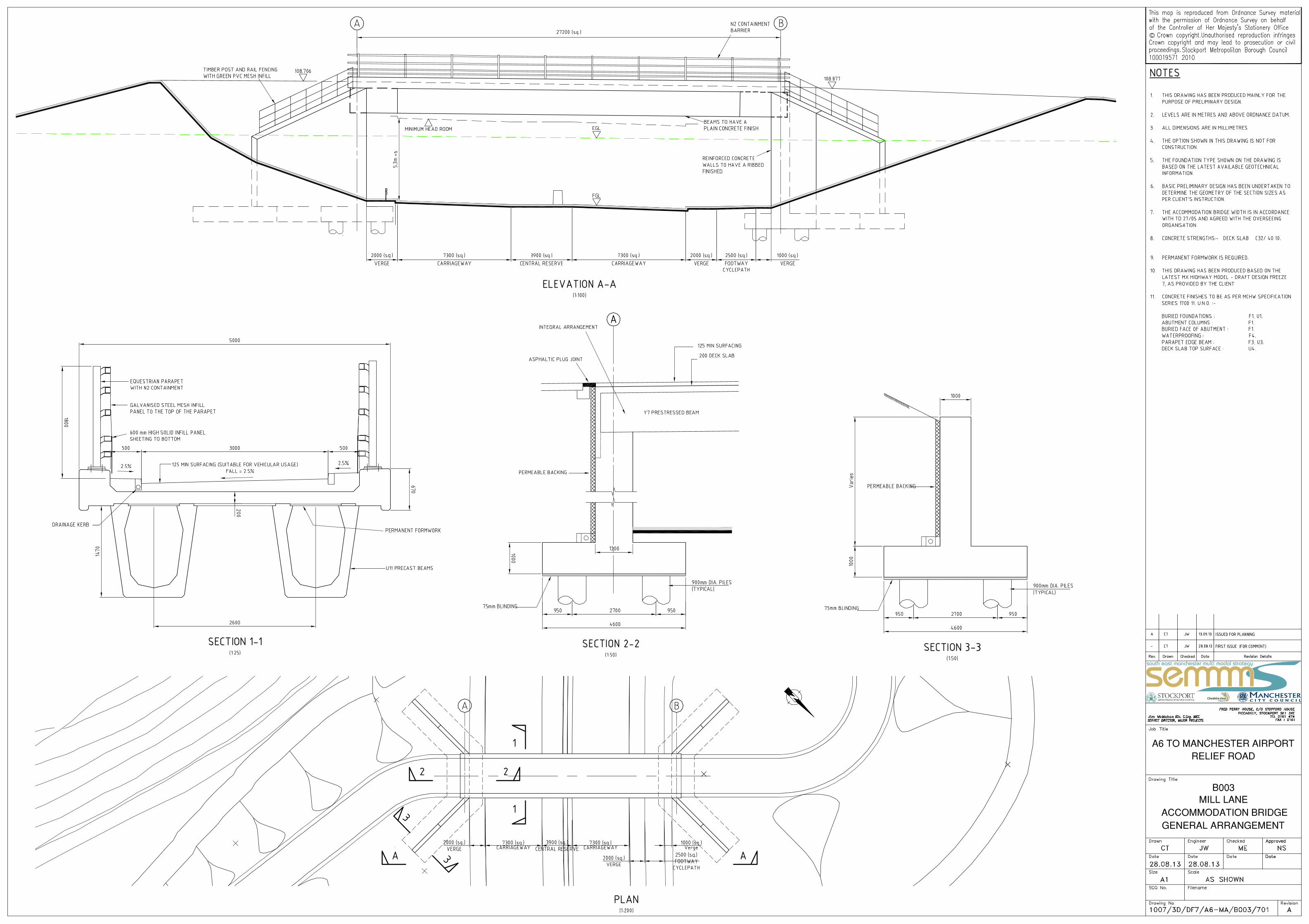
The bridge is located across the line almost exactly above BH1003 (Geotechnical Engineering, 2005). This shows the ground conditions to likely be:
A thin band of sandy CLAY 0.50m thick overlying;
Medium dense to dense SAND and GRAVEL, becoming sandy slightly clayey GRAVEL to a depth of 3.40m bgl;
Beneath this is cohesive GLACIAL TILL to 4.80m bgl which rests on:
Weathered MUDSTONE bedrock. The weathered Mudstone is described as very weak with approximately 40% of its volume weathered to a sandy clay matrix to a depth of 5.40m bgl. The Mudstone is underlain by;
Moderately strong fine and medium grained SANDSTONE encountered to a depth of 5.85m bgl; Weak to moderately weak SILTSTONE was then recorded to a depth of 7.00m bgl being completely weathered in places between 6.00 and 7.00m bgl;
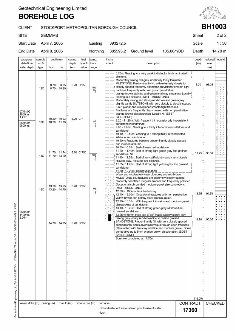
Moderately strong MUDSTONE was then encountered to a depth of 8.70m bgl overlying;
Moderately strong SILTSTONE was encountered to a depth of 11.75. the Siltstone was interbedded with thin beds of sandstone and mudstone throughout;
Weak MUDSTONE was found to underlie the Siltstone to a depth of 13.55m bgl. The Mudstone was interbedded with thin bands of Sandstone. Strong SANDSTONE was then encountered to termination depth of 14.70m bgl.
Groundwater was not encountered prior to use of water flush so an accurate GWL could not be obtained from the drilling. Subsequent monitoring of the standpipe installation showed that the highest groundwater level recorded was 4.71m bgl. A review of the abandonment plans for the Poynton and Norbury collieries shows that the new location for B003 is not underlain by any historical workings and no movement is therefore expected from historic mine workings. As there is only one borehole in the new proposed location for B003 this is considered insufficient and at least two additional holes, one either side of the proposed road, should be drilled to a depth of at least 10.00m bgl to confirm the ground conditions at the bridge abutments. The bridge abutments are to be located at the base of the cutting slope adjacent to the proposed road. The foundations are expected to rest on the bedrock at the base of the proposed cutting. Due to the large moments to be resisted it will be necessary to employ piled foundations socketed into the underlying bedrock. To resist the

B003- Mill Lane Accommodation Bridge Stockport Metropolitan Borough Council Preliminary Design Report
overturning moments it is considered that relatively short large diameter bored piles will be the most suitable. The results of rock testing resulting from the additional boreholes will be required to determine bearing capacity and lateral load resistance for the rock
9. Appearance
The superstructure on elevation comprises of approximately 1.47m deep pre-cast beams and 0.67m string course spanning across the relief road. The beams and slab deck will have a plain concrete finish. In addition, N2 steel parapets will be mounted on the string courses at either side of the bridge with the exposed faces of the abutments and wing walls to be ribbed concrete. Precamber may be introduced to give the bridge a more aesthetically pleasing elevation view. (Please refer to the 3D view of the bridge included in Appendix B).

B003- Mill Lane Accommodation Bridge Stockport Metropolitan Borough Council Preliminary Design Report
Appendix A: Location Plans

B003- Mill Lane Accommodation Bridge Stockport Metropolitan Borough Council Preliminary Design Report
Appendix B: Proposed General Arrangement Drawing
3D Model
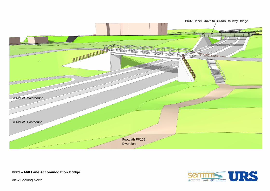
B003 – Mill Lane Accommodation Bridge
View Looking North
SEMMMS Eastbound
B002 Hazel Grove to Buxton Railway Bridge
SEMMMS Westbound
Footpath FP109 Diversion

B003- Mill Lane Accommodation Bridge Stockport Metropolitan Borough Council Preliminary Design Report
Appendix C: Ground Investigation Information
5
nil
nil
C*500
C*375
C 49
C 28
S 31
11
10
9
8
56
6
5.20
43
2
1
100
100
100
0
0
40
24
7
TOPSOIL. (Drillers description) (TS - TOPSOIL)
6.55m: 60mm thick bed of strong fine grained sandstone.
6.00 - 7.00m: Locally disintegrated to lithorelicts in a siltmatrix.
Geo
tech
nica
l Eng
inee
ring
Ltd,
Tel
. 014
52 5
2774
3
173
60.G
PJ
TR
IALJ
H.G
PJ
GE
OE
NG
V49
.GLB
9/5
/05
5.45 - 5.55m: 65° curviplanar rough tight sandy clay smearedfracture.
D*
Moderately strong red-brown and light grey fine and mediumgrained SANDSTONE. (SDST - SANDSTONE)
5.20 - 5.40m: Bed of stiff red-brown clay with occasionalsubangular to subrounded fine and medium lithorelicts andgreen-grey fine gravel size silty reduction spots.
Very weak red-brown MUDSTONE comprising frequentangular blocky fine and medium lithorelicts in a very stiffslightly sandy clay matrix (40%). (MST - MUDSTONE)
4.20 - 4.50m: Drilling disturbed.
Very stiff indistinctly structured red-brown locally grey andorange slightly sandy CLAY with occasional subangular fineand medium mudstone lithorelicts. (CT - COHESIVE TILL)
3.10m: Becoming medium dense.
Dense red and orange-brown silty very sandy angular tosubrounded fine to coarse predominantly sandstoneGRAVEL with occasional fine gravel size coal fragments.(GFG - GLACIO-FLUVIAL GRAVEL)
3.10
Sandy CLAY. (Drillers description) (GFC - GLACIO-FLUVIALCOHESIVE)
5.20
98.06
99.21
99.66
100.26
101.66
103.86
104.26
104.760800hrs07/04/05
5.20
SAND and GRAVEL. (Drillers description) (S&G - SAND &GRAVEL)1.00 1.65
7.207.20
5.705.70
5.20
4.204.20
3.103.10
1.90
91
1.20
3.55
0.50
0.00
C
C
C
X
X
X
XDD*
D*
1.20
3.40
7.00
5.85
1.90
4.80
3.10
1.20
0.80
0.30
8.707.26
7.205.78
5.70
5.204.65
4.20
Weak to moderately weak grey locally red-brown slightlymicaceous SILTSTONE. NI, with very closely spacedrandomly orientated planar and irregular rough tight fissures.Fissures are frequently smeared with red-brown clay andoccasionally discoloured yellow-brown. (STST -SILTSTONE)
5.40
water depth
Ground level385593.2Northing
393272.5Easting
April 8, 2005
(m)
instru
End Date
progressdescription
time to rise (min)
rangelevel
17360Groundwater not encountered prior to use of waterflush.
sampleno &
5.40 - 5.45m: Bed of moderately weak red-brown thinlylaminated siltstone, NI.
casing (m) remarks
date/timedepth
Start Date
EQUIPMENT: Geotechnical Pioneer rig.METHOD: Hand dug inspection pit 0.00-1.20m. Dynamic sampled (128mm) 1.20-1.90m, (113mm) 1.90-5.20m. Waterflush rotary core drilled (116mm) 5.20-14.70m.CASING: 143mm diam to 5.20m.BACKFILL: On completion, a standpipe piezometer (19mm) was installed with tip at 14.70m, granular response zone 14.70-12.70m, bentonite seal 12.70-0.40m,concrete and raised cover 0.40-0.00m.
(m)
{8.00}
legend
105.06mOD
(m)/core
Geotechnical Engineering Limited
rose to (m)
type &test
depth
CHECKED
value
reduced
water strike (m)
Sheet
type
CONTRACT
CLIENT
samp.
tofrom
depth (m)
SEMMMS
STOCKPORT METROPOLITAN BOROUGH COUNCIL
BOREHOLE LOG
1 : 50
casing
1 of 2
April 7, 2005
Continued Next Page
SITE
BH1003
Scale
Depth 14.70 m
-ment
08/04/05
6.70m: Grading to a very weak indistinctly thinly laminatedsiltstone.
90.36
91.51
93.31
96.36
1400hrs
0800hrs
1800hrs
2.26m
C*750
08/04/05
9.20 - 11.20m: With frequent thin occasionally impersistentsandstone interlaminae.
07/04/05
5.20
5.20
5.20
5.20
5.20
C*750
C*750
C*750
1.41m
12.30m: 100mm thick bed of clay.
Geo
tech
nica
l Eng
inee
ring
Ltd,
Tel
. 014
52 5
2774
3
173
60.G
PJ
TR
IALJ
H.G
PJ
GE
OE
NG
V49
.GLB
9/5
/05
C
Borehole completed at 14.70m.
Strong grey locally red-brown fine to coarse grainedSANDSTONE. Predominantly NI, with very closely spacedsubhorizontal and subvertical irregular rough open fracturesoften infilled with firm clay and fine and medium gravel. Somepenetrative up to 5mm orange-brown discoloration. (SDST -SANDSTONE)
13.25m: 60mm thick bed of stiff friable slightly sandy clay.
13.10 - 13.25m: Bed of strong green-grey siltstone/finegrained sandstone.
Moderately strong red-grey indistinctly thinly laminatedMUDSTONE. Predominantly NI, with extremely closely toclosely spaced randomly orientated curviplanar smooth tightfractures frequently with patchy non penetrativeorange-brown staining and occasional clay smearing. Locallytending to a siltstone. (MST - MUDSTONE)
12.40 - 13.00m: Occasional fractures with non penetrativeyellow-brown and patchy black discolouration.
Moderately strong and strong red-brown and green-greyslightly sandy SILTSTONE with very closely to closely spaced5-65° planar and curviplanar smooth tight fractures.Fractures are frequently clay smeared with non penetrativeorange-brown discolouration. Locally NI. (STST -SILTSTONE)
Weak and moderately weak blue-grey and red-brownMUDSTONE. NI, fractures are extremely closely spacedrandomly orientated irregular smooth and frequently polished.Occasional subrounded medium gravel size concretions.(MST - MUDSTONE)
11.70 - 12.20m: Drilling disturbed.
11.55 - 11.75m: Bed of strong light yellow-grey fine grainedsandstone.
11.40 - 11.55m: Bed of very stiff slightly sandy very closelyfissured clay. Fissures are polished.
11.20 - 11.40m: Bed of strong light green-grey fine grainedsandstone. NI.
10.50 - 10.65m: Bed of weak red mudstone.
10.20m: Fractures become predominantly closely spacedand inclined at 0-30°.
10.10 - 10.50m: Grading to a strong thinly interlaminatedsiltstone and sandstone.
9.80 - 9.95m: Grading to a thinly interlaminated siltstone andsandstone.
15
12.70 - 13.10m: With frequent thin veins and medium gravelsize pockets of sandstone.
13.20
8.70
14.75
14.7013.25
13.2011.74
11.7010.23
10.20
C**
14.7014.70
13.20
11.7011.70
10.2010.20
8.708.70
C
C
C
8.75
014
13
12
93
100
85
100
0
0
0
11.75
513.55
79
658
Northing Ground level
Groundwater not encountered prior to use of waterflush.
samp.
SEMMMS
STOCKPORT METROPOLITAN BOROUGH COUNCIL
Scale
range
sample
rose to (m)
-mentinstru
105.06mOD
type &
Easting
value
April 8, 2005
2 of 2
/corecasing
date/time
BH1003
CONTRACT
17360
legendreduceddescription
Depth
BOREHOLE LOGGeotechnical Engineering Limited
depth (m)
typeno &
progress
SITE
time to rise (m) remarks
1 : 50
CLIENT
385593.2
April 7, 2005
{18.00}
test
(m)level
tofrom
14.70 m
water strike (m) casing (m)
393272.5
CHECKED
Start Date
water depth
Sheet
End Date
depth
(m)depth (m)