Embed Size (px)
Citation preview

REPORT DOCUMENTATION PAGE Form Approved
OMB NO. 0704-0188
Public Reporting burden for this collection of information is estimated to average 1 hour per response, including the time for reviewing instructions, searching existing data sources, gathering and maintaining the data needed, and completing and reviewing the collection of information. Send comment regarding this burden estimates or any other aspect of this collection of information, including suggestions for reducing this burden, to Washington Headquarters Services, Directorate for information Operations and Reports, 1215 Jefferson Davis Highway, Suite 1204, Arlington, VA 22202-4302, and to the Office of Management and Budget, Paperwork Reduction Project (0704-0188.) Washington, DC 20503 I AGENCY USE ONLY ( Leave Blank) 2. REPORT DATE
31 Jan 09 3 REPORT TYPE AND DATES COVERED Final Progress Report 8/27/07-8/26/08
4 TITLE AND SUBTITLE Embedded Meta-Material Antennas
5 FUNDING NUMBERS W9UNF-07-I-0602
6 AUTHOR(S) Prather, Dennis W.
7 PERFORMING ORGANIZATION NAME(S) AND ADDRESS(ES) University of Delaware - Research Office 210 Hullihen Hall Newark. DE 19716
PERFORMING ORGANIZATION REPORT NUMBER ELEG332245-020509
9 SPONSORING / MONITORING AGENCY NAME(S) AND ADDRESS(ES)
U. S. Army Research Office P.O. Box 12211 Research Triangle Park, NC 27709-2211
10 SPONSORING / MONITORING AGENCY REPORT NUMBER
11 SUPPLEMENTARY NOTES The views, opinions and/or findings contained in this report are those of the authors) and should not be construed as an official
Department of the Army position, policy or decision, unless so designated by other documentation.
12 a DISTRIBUTION / AVAILABILITY STATEMENT
Approved for public release; distribution unlimited.
12 b DISTRIBUTION CODE
13. ABSTRACT (Maximum 200 words)
With the dawn of the Digital Battlefield, a critical capability in the modern warfare environment is the miniaturization of electronic warfare signal and information processing systems. To realize such systems, the key is to miniaturize antennas that transmit and receive signals. In particular, by introducing reconfigurable antennas, one can combine multiple antennas operating at various frequency bands into a single aperture, which can provide significant miniaturization and flexibility to the entire system. To design such miniaturized antennas, new materials and technologies have to be incorporated. For this purpose, the PI has designed and demonstrated miniaturized antennas by introducing metamaterials such as split ring resonators (SRRs) into the antenna structure. Also proposed and designed were conformal antenna structures with in-plane SRRs for the convenience of integration. In addition, by introducing photo transistors into the SRRs, a frequency tunable antenna was designed. This small reconfigurable planar antenna could be integrated into an Army platform to miniaturize the size of the system while providing additional functionality.
14 SUBJECT TERMS
Meta-Materials, Reconfigurable Antennas, Split-ring resonators 15 NUMBER OF PAGES
22
16 PRICE CODE
17 SECURITY CLASSIFICATION OR REPORT
UNCLASSIFIED
18 SECURITY CLASSIFICATION ON THIS PAGE
UNCLASSIFIED
19. SECURITY CLASSIFICATION OF ABSTRACT
UNCLASSIFIED
20. LIMITATION OF ABSTRACT
I' NSN 7540-01-280-5500 Standard Form 298 (Rev.2-89)
Prescribed by ANSI Std. 239-18 298-102

Embedded Meta-Material Antennas
Final Report
Submitted to the Army Research Laboratory
Submitted by
Professor Dennis W. Prather Principal Investigator
University of Delaware Department of Electrical and Computer Engineering
Newark DE 19716 Phone:(302)831-8170 Fax:(302)831-8172
Email: [email protected]
Date: January 31, 2009
20090210205

1. Abstract
With the dawn of the Digital Battlefield, a critical capability in the modern warfare environment is the miniaturization of electronic warfare signal and information processing systems. To realize such systems, the key is to miniaturize antennas that transmit and receive signals. In particular, by introducing reconfigurable antennas, one can combine multiple antennas operating at various frequency bands into a single aperture, which can provide significant miniaturization and flexibility to the entire system. To design such miniaturized antennas, new materials and technologies have to be incorporated. For this purpose, we designed and demonstrated miniaturized antennas by introducing metamaterials such as split ring resonators (SRRs) into the antenna structure. We also proposed and designed conformal antenna structures with in-plane SRRs for the convenience of integration. In addition, by introducing photo transistors into the SRRs, a frequency tunable antenna was designed. This small reconfigurable planar antenna could be integrated into an Army platform to miniaturize the size of the system while providing additional functionality.
2. Introduction
Emphasis on the ability to efficiently transmit and receive electronic signals in military platforms requires suitable antennas with reduced size and weight. In addition, there is a seemingly perpetual need to miniaturize deployed systems. As such, these requirements present significant challenges in the development of requisite antennas, in that they require smaller, thinner, lower profile, and more frequency agile antennas. Moreover, these demands are made even more difficult when considering that most antennas need to be of a certain electrical size in order to perform efficiently, which is governed by a fundamental relationship between gain and bandwidth. This relationship sets strict limitations on the amount a given antenna can be reduced in physical size, while concomitantly increasing its bandwidth and radiation efficiency. As a result, it becomes increasingly more difficult to reduce an antenna's size without compromising its bandwidth. Furthermore, in the modern warfare environment, it is critical to rapidly and accurately detect and process electronic signals with an ever increasing spectrum. Therefore, there is a significant interest in reducing the physical size of antennas while at the same time increasing, or at the very lease preserving, its bandwidth.
While the challenges set forth above are indeed challenging, recent developments in the area of novel artificial materials, i.e., metamaterials, have offered some possible solutions. In short, metamaterials are a newly emerging class of artificially engineered materials that exhibit electromagnetic behavior that is not common in nature. One of their attractive features is that they can be engineered to have functional electromagnetic properties over a desired frequency range. Recently, a significant improvement in antenna performance has been shown for a class of metamaterials exhibiting a high positive magnetic permeability, otherwise known as artificial magnetic inductors. Antennas exploiting the feature of metamaterials have shown the potential for miniaturization of the overall antenna system while simultaneously operating over a broader frequency bandwidth.
In this project, we used metamaterials, such as SRRs, to realize an inductive material that serves to lower the antenna's resonant frequency, thus leading to a reduction in the physical size of the antenna. The main advantage of this approach, over conventional antenna miniaturization techniques, is that the antenna efficiency-bandwidth compromise is kept to a minimum. Also, the small size of the antenna serves to ensure that there is minimum intrusion to the structural support. Furthermore, such an approach may lead to the ability to introduce aspects of reconfigureability to the antenna.

2.1. Project Achievements/ Deliverables
1) Designed and modeled metamaterials for antenna miniaturization 2) Demonstrated numerically and experimentally the miniaturization of narrowband antennas such as loop and patch antennas 3) Demonstrated numerically the miniaturization and tunability of a wideband antenna, such as a stacked-patch antenna 4) Designed and demonstrated experimentally reconfigurable antennas based on metamaterials
3. Antenna Miniaturization with Embedded SRRs
Fig. 1: Relationship of inductance with resonant frequency of the antenna.
While most situations stand to benefit from smaller antennas, in certain applications it is simply imperative. This is especially true in the field of RF communications, where reducing the size of an antenna leads to smaller and lighter-weight systems, thereby enhancing portability and minimizing electromagnetic interference with other electronic devices. To this end, the
motivation for developing techniques that allow for the physical reduction in antenna size, while at the same time either preserving, or increasing its electrical size. Thus, in accordance with this goal we have investigate designs for resonant antennas based on metamaterials that are electrically
responsive in a given frequency range, yet physically small in comparison to conventional antennas in that range. The challenge in realizing this goal arises from the fact that as the antenna size is reduced, its wavelength dependence posses a strict limitation on the dimension of the antenna, thus, making it harder to reduce its size. To overcome this limitation, alternative designs based on synthetic (or metamaterial) reactive components need to be considered. Accordingly, it has been shown that such resonant antennas can indeed be miniaturized using metmaterials, or artificial magneto dielectrics, while maintaining and improving the bandwidth of operation. The fundamental reason for this is based on the fact that the resonant frequency of an antenna is inversely proportional to its inductance (L) and capacitance (C), such that an increase in either will decrease the resonant frequency. As a result, in order to increase the resonant frequency back to its original value, the physical dimension of the antenna must be reduced, thus resulting in an antenna with a smaller physical dimension. Furthermore, an inductive element is preferred over a capacitive one, as the former leads to an increase in bandwidth. However, typical inductive elements are based on ferromagnetic materials, and, unfortunately such materials have a very weak electromagnetic response in the GHz frequency range. To overcome this limitation, the use of artificial magnetic materials has been considered. They are often realized using a structured called a Split Ring Resonator (SRR), which has been shown to exhibit paramagnetic behavior well into the high GHz range.
Effective permeability
i 1 WY*
' •'•"'I
Fig. 2: Typical dispersive behavior of a medium* densely filled with metasolenoids (the part with lines denotes the resonant region, the grey part denotes the effective material region) * P. Ikonen et. at.. Microwave and Optical Technology Letters, Vol. 46, page- 205, 2005

Effectively, there are two distinctive paramagnetic regions of SRRs; one that occurs immediately before the resonance where the permeability value is very high and changes rapidly with frequency (region-I) and the other, which occurs in the region well before the onset of the resonance. In the latter case, the value of the permeability remains relatively constant and, as such, is referred to as the static effective permeability region (region-II). This is duly noted in Fig. 2. In comparison, region-1 provides a high permeability value and thereby a higher inductance, however, its narrow bandwidth can present a limitation. Hence, in our applications, the preferred region is the effective permeability region (region-II), where the collective SRRs can be treated as an effective media with a relatively high permeability value and a concomitant wider bandwidth.
In the remainder of this report, we present two areas relating to the miniaturization of different antenna systems. First, we demonstrated miniaturization of conventional narrowband antennas. In particular, we showed that by implementing SRRs in certain configurations relative to the antenna, in this case loop and patch antennas, that they can be used to reduce the physical size of the antenna. Initially, we employed numerical tools to design the SRRs and embedded meta- antennas. Following that, with encouraging simulation results, we fabricated prototype antennas and loaded them with the designed metamaterials to experimentally verify the simulated results. We also investigated the limitation of the metamaterials, in terms of different antenna factors, e.g., bandwidth and gain. Secondly, we proposed a design approach to miniaturize wideband systems, thereby overcoming the challenges of only applying these techniques to narrowband antennas. In particular, we focused on double-stacked patch antennas, where the metamaterials were successfully implemented to reduce the size of the overall antenna. Lastly, we exploited the tunability feature of the SRRs to design reconfigurable antennas. Functionality of such antennas was demonstrated both numerically and experimentally. Details of these results are presented below.
4.1. Narrowband Antenna Miniaturization: Loop Antenna
4.1.1. Out-of-plane SRR Configuration
Fig. 3. Shift of the resonant frequency with out-of- plane SRRs. (Inset) Loop antenna on top of SRR slabs.
Antenna miniaturization is important at or below S band (2-4 GHz), especially in the ISM bands for RFID (2.4 GHz) and GPS receivers (L band, 1-2 GHz). Thus, to study how to reduce the physical size of antennas, we considered loading antennas with metamaterials, and investigated the impact of split ring resonators (SRRs) on some of the main antenna parameters such as: gain, impedance, front to back, resonance and effective electrical length.
The simulated loop antenna and the setup are shown in Fig. 3, where the antenna is sitting on top of a stack of ring resonators. The simulation was performed in Ansoft HFSS, where lumped ports were used as the source for the antenna. We designed an antenna having the dimension of approximately one quarter-wavelength on each side, such that the total perimeter was approximately one wavelength. Two rows of five SRRs, each with a dimension of 5 mm x 5 mm, were imprinted on an FR4 substrate. The SRRs had a higher resonant frequency than the antenna, enabling it to exploit the paramagnetic region of the rings which were electrically induced by the magnetic field generated from the flow of the current on the loop. To cover the entire area under

the loop, eight substrate slabs, each having a 2 mm thickness and 13 mm height were used. The period of the stack was 2 mm. The dimension of the loop antenna was 30.5 mm x 32.5 mm and had a resonant frequency of 2.58 GHz, in free space. As shown in Fig. 3, with the introduction of the FR4 slabs only, the resulting shift in the antenna's resonant frequency was 2.24 GHz and the resonant frequency of the antenna with the SRRs imprinted on the FR4 substrate was 1.97 GHz. Thus, the percentage shift of the resonant frequency was 23%, or, in the other words, the size reduction factor was 0.23. We also noted that, with a substrate having a higher dielectric (Rogers RO3010, 8= 10.2), the frequency was further reduced to 1.76 GHz.
4.1.2. In-plane SRR Configuration
Although these out-of-plane designs showed potential for miniaturizing the antenna, the volume of the overall setup was not optimal and the overall fabrication process and setup would be difficult and cumbersome. Hence, we proposed a new setup, as shown in Fig. 4 (a), where the SRRs were placed in-plane with the antenna. The motivation for this configuration stemmed from the fact that the magnetic field is rotationally symmetric around the current carrying path of the loop; as such, the in-plane SRRs would serve the same purpose as the out-of-plane SRRs. However, the added advantage of this configuration is the monolithic design which would boost the ease of the fabrication procedure. In the following, we describe our approach for this kind of modeling.
- Loop only
- Loop with aingtB !ay*f SRR
- Loop wilti doobla lay* SRR
- Loop with tnpia lay w SRR
Fig. 4(a). In-plane SRR configuration. Fig. 4(b). Radiation pattern of
the loop antenna with the in- plane SRRs.
Fig. 4(c). Shift of resonant frequency of the loop antenna with the in-plane SRRs.
Rings of dimension 9 mm x 3 mm with the resonant frequency of around 2.8 GHz were placed 1 mm away from the antenna and from each other on the same plane around the loop. As shown in Fig. 4(a), layers of SRRs were placed both outside and inside the loop, with the outside layers going away from the antenna. The substrate was Rogers R03010. With the introduction of the first layer of SRRs, the resonant frequency of the antenna went down to 1.7 GHz from 2.58 GHz and with the addition of extra layers, the resonant frequency went down to 1.6 GHz, as shown in Fig. 4(c). Hence, with the in-plane configuration the miniaturization of the antenna was also possible up to 37.9%! We also studied the radiation pattern of the loop antenna for different layers of SRRs on the plane. The gain of the original loop antenna was 3.79 dB. This value changed to 3.36 dB when the rings were introduced. The reason for such a small change in the gain is due to the surface area of the loop being very small; hence interaction with the antenna and the rings is a minimum. Lastly, we noted that the radiation pattern of the loop was bi directional as was expected.
4.1.3. Distribution of SRRs and its Effect on Antenna Gain and Effective Permeability
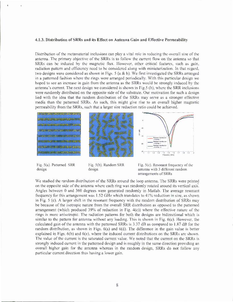
Distribution of the metamaterial inclusions can play a vital role in reducing the overall size of the antenna. The primary objective of the SRRs is to follow the current flow on the antenna so that SRRs can be induced by the magnetic flux. However, other critical features, such as gain, radiation pattern and efficiency need to be considered along with miniaturization. In that regard, two designs were considered as shown in Figs. 5 (a & b). We first investigated the SRRs arranged in a patterned fashion where the rings were arranged periodically. With this particular design we hoped to see an increase in gain from the antenna as the SRRs would be strongly induced by the antenna's current. The next design we considered is shown in Fig.5 (b), where the SRR inclusions were randomly distributed on the opposite side of the substrate. Our motivation for such a design lied with the idea that the random distribution of the SRRs may serve as a stronger effective media than the patterned SRRs. As such, this might give rise to an overall higher magnetic permeability from the SRRs, such that a larger size reduction ratio could be achieved.
ISSllSEJLSEilSEJlSS iSEJISS
LssJlssJlssJlssJlssJlssJlss
IssJlssllssJlssllssJlssJtss.
•SslCsslE&tssltsSl^slEE:
ssltsiiltsalssJSsjl^sJlss.
ssJlseJ&sJls&JGgsKsslC
/If ^_^_ Random tfulnbution
ofSRRi- 1 ^^^_ Rmdwn dwlnbulton
of SRR*-II
•~ oTSRRs-M
Vf 13 14 15 16 17 1.8 19
Fr»qu«ncy (GHz)
Fig. 5(a). Patterned SRR design
Fig. 5(b). Random SRR design
Fig. 5(c). Resonant frequency of the antenna with 3 different random arrangements of SRRs
We studied the random distribution of the SRRs around the loop antenna. The SRRs were printed on the opposite side of the antenna where each ring was randomly rotated around its vertical axis. Angles between 0 and 360 degrees were generated randomly in Matlab. The average resonant frequency for this arrangement was 1.52 GHz which translates to 41% reduction in size, as shown in Fig. 5 (c). A larger shift in the resonant frequency with the random distribution of SRRs may be because of the isotropic nature from the overall SRR distribution as opposed to the patterned arrangement (which produced 39% of reduction in Fig. 4(c)) where the effective nature of the rings is more anisotropic. The radiation patterns for both the designs are bidirectional which is similar to the pattern for antenna without any loading. This is shown in Fig. 6(c). However, the calculated gain of the antenna with the patterned SRRs is 3.37 dB as compared to 1.87 dB for the random distribution, as shown in Figs. 6(a) and 6(d). The difference in the gain value is better explained in Figs. 6(b) and 6(e), where the induced current distributions on the SRRs are shown. The value of the current is the saturated current value. We noted that the current on the SRRs is strongly induced current in the patterned design and is roughly in the same direction providing an overall higher gain for the antenna whereas in the random design, SRRs do not follow any particular current direction thus having a lower gain.

•:11 A 11 * Fig. 6(a). Gain of the antenna with the patterned SRRs
ill saofecc ankEc osaiccc aaaiBBG analb seco
-Only Loop Loop with Patterned
"SRRs
Loop with random "SRRs
Fig. 6(c). Radiation pattern of the antenna with different loadings
Fig. 6(b). Induced current on the patterned SRRs
Fig. 6(d). Gain of the antenna with the random SRRs
I *s% SE* ^ I J > Zmdwm
nLV/1 Il^ll \& Fig. 6(e). Induced current on the random SRRs
The modeling presented here provided insight into the behavior of metamaterials and their role in the miniaturization of antennas. These ideas were further developed for patch antenna applications.
4.2. Narrowband Antenna Miniaturization: Patch Antenna
1 Patch antenna with periodic • dielectric and SRRs
5
S4 1.78! 2.08
' A>i T•^ K^ NJ
\ 1
11 / £-|U
^| ^ 35 -15
A ir filled Dielectrics fill With SRRs
:i y^ X
V=60m 1=10m
m
n 1
-30 15 2 2 5
Frequency (GHz)
Fig. 7(a). Stack of split-rings underneath a path antenna.
Fig. 7(b). Frequency shift of the patch antenna's resonant frequency
In this design, the simulated setup shown in Fig. 7(a) corresponds to a stack of ring resonators that is sandwiched between a patch antenna and a ground plane. A coaxial line was used as the feeder for the patch antenna structure, which was analyzed using our custom FDTD code. As in the case of the loop antenna, the magnetic fields from the antenna induced currents on the rings, which, results in a corresponding shift in the resonant frequency, as shown in Fig. 7(b). In this figure, the blue curve was the resonant frequency of the antenna at 2.08 GHz for a dimension of

60 mm x 60 mm and the red curve at 1.484 GHz was the resonant frequency after introducing the rings in the structure. With the FR4 substrate only the resonant frequency of the antenna shifted to 1.785 GHz from its original value of 2.08 GHz.
Antenna Air filled SRRs+Dielectrifilled
Dimension
(WxLxH)mra
60x60x10 42.8 x 42.8x7.1
Reduction factor 1 0.71
Fig. 8(a) Miniaturization of the patch antenna
ID
ffl-10
"-20
-30
-40
^ r Air fil WithS RRs
0.5 1.5 2 2.5 Frequency (GHz)
3.5
Fig. 8(b). Shifting back of the resonant frequency of the miniaturized patch antenna
Following this analysis, wherein the percentage of frequency shift was 28.6%, we reduced the patch antenna by a similar amount, as shown in Fig. 8(a). In this case, the resonant frequency shifted back to the original frequency of the antenna at 2.08 GHz. As a result, the new shifted frequency had a higher Q-value, which was expected as a result of introducing the SRRs underneath the antenna. As pointed out in the previous section, a similar observation was made in the case of the loop antenna.
4.2.1 Effect of Package Density of SRR on the Miniaturization of Patch Antenna
In addition to the above analysis, we also studied the packaging density of the ring structures with the expectation that by increasing the density of the rings the resonant frequency would be shifted down even further, thereby enabling a further reduction in antenna size. This is demonstrated in Fig. 9, where the periodicity was varied from 2 mm to 5 mm. The structure having a 2 mm periodicity had a resonant frequency that was much lower than that for the 5 mm structure. (The result shown earlier was for 2 mm periodicity of the ring stacks).
4.2.2. Radiation Pattern of Patch Antenna
We further investigated the radiation pattern and gain of the patch antenna, with and without the SRR slabs as shown in Fig. 10. In this case the off-centered feed to the antenna was in the x-direction and the stacking of the slabs was in the v-direction. The gain of the patch was 9.619 dB and the radiation pattern was very directional as was expected. Because the feed for the antenna was off-centered, the resulting radiation pattern was not symmetric, as shown in Figs. 10 (a) and (b). With the introduction of the SRRs the gain value decreased to 5.94 dB. We believe this was due to the large surface area of the patch and the
1.5 2 Frequency ((Hz)
Fig. 9. Variation of the period of SRRs in the y- direction to study the package density of SRRs affecting the resonance of the antenna.
10

corresponding increased interaction with the SRRs. Also, the side lobes in the radiation pattern are due to the ground plane that did not extend to infinity in the simulation.
Fig. 10(a). Radiation pattern of patch antenna on Fig. 10(b). Radiation pattern of patch antenna on XZ plane YZ plane
4.3. Narrowband Antennas: Prototype Design and Measurements
Fig. 11(a). Prototype patch antenna Fig. 11(b). Patch antenna measured data
The results obtained from the simulation for the patch antenna miniaturization led us to build prototypes of the designed antenna as shown in Fig. 11 (a). The dimensions of the rings and the antenna are the same as that of the simulation. The rings were fabricated on Rogers Duroid 5880 substrate of permittivity of 2.2 whereas in the simulation FR4 substrate was used. Standard lithography and wet etching processes were used for fabricating the rings. We used a comb-like structure to hold the strips of the rings with equal spacing. We measured the S11 parameters as shown in Fig. 11 (b). The resonant frequency of the antenna without the SRR loading was 2.1 GHz which shifted to 1.8 GHz with the SRR loadings demonstrating a shift of about 12%. It is important to note that in the simulation the substrate material's permittivity was 4.4, as a result the miniaturization factor was higher compared to the measured data with Duroid. Nevertheless, we were able to demonstrate the miniaturization of the patch antenna experimentally using the SRR loaded substrate.
Also, with the promising results obtained from simulation for the loop antenna, we proceeded to design a 1.85 GHz dual loop antenna. This work was performed at Army Research Laboratory (ARL). The loop was approximately one wavelength long. SRR slabs, each containing 9 mm x 3 mm rings arranged in a 5 x 2 array fashion, were sandwiched between the loop antennas, as shown in Fig. 12(a). The antenna consisted of a driven element and a slightly shorter director
11

element. The frequency decrease ranged from approximately 1.85 GHz to 1.65 GHz as shown in Fig. 12(b). There was an increase in bandwidth for the SRR loaded dual loop antenna. Thus, the experimental results justified the assumptions made through the simulation concerning a corresponding shift in the resonant frequency of the antenna.
Fig. 12(a). The loaded antenna configuration. Fig. 12(b). SI 1 showing the frequency shift for unloaded (green trace) and loaded with SRRs (brown trace).
4.4 SRRs and Antenna Bandwidth Analysis
In this section, we discuss and present results on the limitation of the SRRs in terms of enhancing the bandwidth of the antenna. Thus far, we noted that the SRRs have been effective in terms of miniaturization, providing a physical size reduction of around 40%! However, the SRRs tend to have a narrow bandwidth because of its strong resonant nature as a result it is difficult for a narrow band width antenna such the loop and patch antennas to exploit the typical high permeability value that is generated by the SRRs. This is explained in detail from our unit cell study of a SRR as shown in the fig. 13. A unit cell of 9 mm x 3 mm SRR on a Rogers Duroid substrate was simulated in Ansoft HFSS. A Perfect Electric Conductor (PEC) boundary condition was applied along the vertical axis of the SRR whereas a Perfect Magnetic Conductor (PMC) boundary condition was applied perpendicular to the ring and the wave vector k was along the gap of the SRR. The boundary conditions helped to mimic an infinitely periodic structure of SRRs.
1 — ^.-1
i I
H :
, ;. . -I 4. J- i. .;
I—-'.. 1
1 1± i.-=mz_.
Fig. 13(a). Unit cell of a SRR
Fig. 13(b). Magnetic response of the SRR
Fig. 13(c). Electric response of the SRR
12

From the simulation, the scattering parameters (S21 and Sll) were obtained. Using the transmission/ reflection formulation the permeability and permittivity values of the SRRs were extracted as shown in Fig. 13 (b & c). These parameters gave further insight into the bandwidth enhancement of an antenna. We considered a square patch antenna's bandwidth as given in the following:
BW = 96V/V^Mo
•Jl 4 + \7yfJl£
where BW is the bandwidth of the antenna, u and e are the permeability and permittivity of the substrate loading (in our case SRRs on a substrate) of the antenna respectively. For a given thickness of the substrate, t, and an operating wavelength, X„, we noted that the bandwidth of the antenna could be increased only if the /J was larger than 1 and greater than e of the substrate. For example, at a frequency of 2.4 GHz, BW for a patch with air substrate (u=l, e=l): ~ 1/21 and the calculated BW for a patch antenna with magneto dielectric substrate (u=1.3, s=2.9) ~ 0.37/21 (from Fig. 13 (b & c). Although the SRR provided permeability larger than 1, it could not surpass the effective permittivity of 2.9 of the substrate. Thus, an enhancement of BW was difficult to achieve only with SRRs. However, on the positive side, to achieve the same miniaturization factor for the patch with dielectric alone, a higher permittivity value of 3.5 would be required instead of 2.2, as it was in our case. A higher permittivity would increase the capacitance underneath the patch thereby decreasing the overall efficiency of the antenna. Thus, an SRR loaded substrate provided a sufficient miniaturization factor along with other attractive features such as radiation efficiency but could not deliver appreciable BW for the patch antenna. In the next section, we investigated a different approach to mitigate the issue of the bandwidth.
5.1. Wideband Antennas: Stacked Patch Antenna
With regards to bandwidth enhancement, the ultimate limitation has been the narrow frequency range of the SRRs over which the high permeability value remains constant. In order to circumvent this problem, we proposed to miniaturize antennas that inherently posses a large bandwidth. A good candidate to meet that requirement would be a stacked patch antenna. Thus, in the following section we describe the modeling and design of the miniaturization of a wideband antenna.
5.1.1. Design and Miniaturization of a Wideband Stacked Patch Antenna
Our design of a two-layer microstrip patch antenna consisted of a driven bottom patch and a parasitic top patch. The driven bottom patch had its own resonant frequency whereas the top patch antenna electromagnetically coupled with the bottom patch giving rise to a second resonant frequency.
The resonant frequencies for both the patches combined to give a large bandwidth. The route to miniaturization followed a shift of both resonant frequencies simultaneously by placing the SRRs of slightly higher resonant frequencies than the antenna, perpendicularly underneath the patches. SRRs were induced by the magnetic field that was generated from the current flowing on the patches. With the rings normal to the magnetic
Fig. 14. Stacked Patch Antenna fjg]^ srr0ng magnetic induction would be ensured.
13

Our approach for implementation was as follows. At first, we built a single patch antenna sitting on top of a stack of dielectric slabs and noted its resonant frequency. An additional patch on top of the bottom patch of slightly larger dimensions was added and separated by a layer of dielectric slabs as shown in Fig. 14. A second resonant frequency would occur which would be separated from the original resonant frequency by a certain percentage based on the larger dimensions of the top patch. Following that, we would add the SRRs on the bottom and top slabs which would shift both the resonant frequencies of the bottom and top patch simultaneously. The ratio of the dimensions of the top rings to the bottom rings would be equal to the ratio of the dimensions of the top patch to the bottom patch. The manufacturing of the SRRs was based on our previous experience in miniaturizing single patch antennas. Therefore, by reducing the actual physical dimensions of the antenna by the same percentage of the frequency shift we would be able to miniaturize the physical size of the double-patch antenna maintaining a large bandwidth. For additional analysis, we calculated the gain and radiation pattern of the antenna.
5.1.2. Modeling and Simulation Results
Typically, stacked patch broadband antennas are shown to have bandwidth in the order of 10- 20% and gain can reach 8-11.7 dBi. Our purpose was to obtain similar numbers but with a miniaturized version of the broadband antenna.
1—«- J
1 1
r "~"k f
if ! /
- ~ - 1
i 4- -4 1 -( f T mMftir, J
• T
ll
f ,
j •
Fig. 15. Permeability and permittivity of the top SRRs of dimensions 10.17 mm x 3.38 mm at 2.4 GHz
j — Mpavymr
J ^ /
I i
1 1 ' i
>
\ / u \
|
i
.
Fig. 16. Permeability and permittivity of the bottom SRRs of dimensions 9 mm x 3 mm at 2.9 GHz
We modeled the broadband antenna using Ansoft HFSS, commercial 3-D full-wave simulation software. The setup was the same as shown in Fig. 14, where the dimensions of the top patch were 40 mm x 40 mm, whereas the dimensions of the bottom patch were 37.4 mm x 37.4 mm. The ground plane sitting underneath the bottom patch antenna was 400 mm x 400 mm. The top
14

patch was 6.5 % larger than the bottom patch. Thus, the SRRs placed underneath the top patch were enlarged by the same percentage so that it could shift the resonant frequency of the top patch. The SRRs were printed on the substrates with permittivity value of 2.2. The width of the substrates was 1 mm and the gaps between the subsequent slabs were 3 mm. The dimensions of the SRRs underneath the bottom patch were 9 mm x 3 mm. At 2.9 GHz, the bottom SRRs' permeability value was 1.3 and the permittivity value was 2.8 as shown in Fig. 17. Whereas, as shown in Fig. 15, the permeability value of the SRRs underneath top patch was 1.2 and 2.8 respectively at 2.4 GHz. The bottom patch antenna was aperture coupled.
H-*i
^Zq^ p4^j4 ij..
X \-Y--\; \\f With aaectrcs only
__ Stacked patch with dSedrics aro rcgs
i 1 : i i 2 2 2 3 2 4 2 5 2 6 2 7 2 8 2 9
Frequency (OHi)
Fig .17(a). Frequency response of the stacked patch antenna
Fig. 17(b). VSWR of the stacked patch antenna
Figure 17 (a) shows the different frequency responses of the stacked-patch antenna with and without the SRRs. At first, the patches were placed on top of the dielectric slabs without the SRRs. The frequency response (SI 1 parameters) for that case is shown in Fig. 17(a) with the blue curve indicating a 26% bandwidth for the antennas with a resonant frequency of 2.7 GHz. Following that, the SRRs were added to both the top and bottom dielectric slabs and a noticeable shift was noted in the frequency as shown by the red curve. The new resonant frequency as shown with the red curve was 2.345 GHz. In particular, a shift of 13% was noted and the arrows in the graph indicated that the frequencies at 2.95 GHz shifted to 2.55 GHz and 2.4 GHz shifted to 2.14 GHz at the -10 dB point, respectively. However, the significant parameter was the impedance bandwidth of the shifted curve which was 18%. Thus, by introducing the SRRs we achieved a 13% smaller antenna with a relatively large impedance bandwidth of 18%.
It is important to note that in Fig. 17(a), the red curve's first dip at the 2.14 GHz mark is shallower compared to a larger second dip contributed by the bottom patch and its corresponding SRRs. This difference may be best explained by looking at Fig. 17(b) and the inset picture, where it was noted that the top patch's magnetic field that was responsible for inducing its corresponding SRRs was much weaker than the bottom patch. As such the VSWR for the second dip was below 2 whereas the first dip is at 2.2 as shown in Fig. 17(b) in red curve. Nevertheless, a VSWR of 2.2 would indicate there is only a 0.6 dB transmission loss which is still acceptable for a working wideband antenna. Following this, we calculated the gain and the radiation patterns as shown in Fig. 18. The gain of the double patch antenna with the dielectrics only was 7.3 dB which reduced to 5.6 dB after the introduction of the rings. The radiation patterns showed that there was some energy leaking from the backside which was due to the slot feeding of the antenna. In particular, the front to back ratio of the antenna without the SRRs were 20 dB whereas the ratio went down to 17.4 dB with the SRRs.
15

'otil |dk
5«Uf1 S-Hvl
Fig. 18(a). Radiation pattern of the stacked patch without the SRRs
Fig. 18(b). Radiation pattern of the stacked patch with the SRRs
5.1.3. Antenna Performance Analysis
In this part of the project, we wanted to build a platform for comparing the performance of the wideband antenna with different loading materials. In the following we elaborate on the performance analysis of the simulated stacked patch antenna.
Electrically small antennas have a fundamental limit governed by the quality factor and is given as Q > 1/ (ka)3, where a3 ~ V (volume), /= resonant frequency, Q = quality factor, and k = wave vector. This concept could be extended to compare antennas with a better performance in terms of bandwidth and size. In particular, when comparing between two antennas operating at the same frequency but with different physical volume, the antenna with the smaller Q*V would be better in terms of higher bandwidth and smaller size. Similarly, when comparing two antennas operating at different frequencies occupying the same volume, the antenna with smaller Q*f would be better in terms of bandwidth and size. In both of the scenarios, the goal would be to bring the product, namely the figure of merit (FOM), to a minimum. The FOM could be utilized to measure the performance of the different antenna designs. In Table 1, we present the figure of merit comparisons for the stacked patch antenna with different loadings. We noted that, on the fifth column of Table 1 the FOM decreased significantly as the SRRs with dielectrics were introduced which was due to the decrease in the resonant frequency (2nd column) thereby increasing the miniaturization factor without changing the quality factor (fourth column) drastically. This was primarily because in the figure of merit calculation the resonant frequency is cubed, hence any change in the resonant frequency or the miniaturization factor would impact the FOM significantly. In particular, the FOM of the wideband antenna on air was 93.5 with a resonant frequency of 2.9 GHz. With the introduction of the inductive SRRs the FOM went down to 71.70 with the resonant frequency at 2.35 GHz maintaining a bandwidth of 18%. Thus, we demonstrated preliminary results for miniaturization of a broadband antenna using metamaterials.
Simulation results suggested that we could achieve a size reduction factor of 13% for a stacked patch antenna while maintaining a broad bandwidth of 18%. The radiation pattern and gain were in accord with the traditional broadband antennas with good front to back side ratios. Currently we are working on the fabrication and experimental verification of the simulation results and hope to present the results in the future.
16

Antenna with
loadings
Res.Freq (fres)(G//z)
BW (%) (Af/fres)
Qo(%) Qo *fres (FOM)
Air 2.9 27% 3.7 93.5
Dielectrics (Rogers)
2.7 26% 3.9 75.78
SRR loading
with dielectrics
2.35 18% 5.56 71.70
Table 1. Figure of merit comparison for stacked patch antenna
5.2. Stacked Patch antenna with Tunable Layers
Fig. 19 (a). Tunable stacked patch antenna
j !
-N-^ p\] t"~br V-j \-l-.-j-
:- •—V —•jA-jf-X-jf— — No SRRs
^^_ DouW« laytrof
Double
clostd
aytrof SRRs
' V I
Fnequenr i.i iGH:
Fig. 19 (b). Frequency response of the tunable stacked patch antenna
In this effort, we investigated the tunability feature of the SRRs and its applicability to our stacked patch antenna design. The SRRs strong resonance primarily originates from the split. As such, closing the gap would destroy the resonance making the SRR loose its resonance effect. Our goal was to switch from the resonant mode of the antenna to a non-resonant mode using the SRRs. We implemented this idea as shown in Fig. 19(b) where the red curve shows the frequency response of the antenna without any SRRs and the blue curve represents the antenna's response with the open rings. As was noted, with the gap in the rings closed as shown in Fig. 19(a), the resonant frequency went back and aligned with the red curve again as shown by the green curve in Fig. 19(b). This was expected as the closed rings did not have the resonant effect anymore and did not affect the antenna. However, the red and the green curves were not an exact match because the closed rings still possessed some inductive effects from the metal portion of the ring as such it would not be completely 'invisible' to the antenna. The switch between the open and closed cases produced a shift in the antenna's resonant frequency by 11.7 %. As was calculated before, the bandwidth of the antenna with the open rings was 18% and with the closed rings the
17

bandwidth was 17%. Thus, we noted that the SRRs were effective in the reducing the physical size of a wideband antenna and could also be useful in tuning the resonant frequency efficiently by maintaining the impedance bandwidth of the antenna. In the next section, we will build on this tunable concept and present the design of a reconfigurable antenna by utilizing SRRs and photo- transistors.
6. Design of Reconfigurable Antenna
The development of tunable antennas has attracted considerable interest in recent years for various applications, such as the need to combine multiple antennas operating at various frequency bands into a single antenna. A driving motivation for this is the limited space available for the placement of multiple antennas on Army platforms as well as the electromagnetic interference (EMI) that such antennas create. In addition, there is also significant interest in reducing the physical size of antennas while preserving the frequency with which they operate. In all of the above cases, it becomes increasingly difficult to keep the antennas tuned to their receivers over wide bandwidths. In particular, this reduces to a problem of impedance matching the antennas assembly to the receiver system. Our approach to realizing a system capable of achieving wide bandwidth operation was to use meta-material devices that would allow for the dynamic tuning of the antenna. To this end, we will show that multiple functionalities could be obtained by introducing meta-material split ring resonators (SRRs) as tunable impedance devices for broad bandwidth antenna receivers. As such, SRRs are sub wavelength resonators with frequency-selective behaviors that would serve to exhibit a tunable inductance by virtue of an induced current around its loop at resonance. As is well-known, SRRs have been used in the design of antennas in order to miniaturize antenna size while preserving its frequency of operation by way of inductively loading the antenna. Another important aspect of the SRRs is their potential application to the design of reconfigurable structures, namely, the electronically controlled or tunable devices, such as very broad bandwidth antennas. In this application, we demonstrate the tunability of the SRRs, and thereby an electrically tunable antenna, by using a transistor at the junction of the SRR. The transistor serves to change the local capacitance in the SRR, thus tuning the resonant frequency and, hence, its ability to inductively load an antenna. To this end, one can control the resonant frequency of antenna as well as its output impedance, which could be used to ensure a very efficient and widely tunable antenna system.
In particular, by introducing a transistor and related active matching network into the system, the antenna can be transformed into an active component that would no longer be limited by the gain- bandwidth-size constraints of passive antennas. In this case, it would be desirable to model an antenna as a multi-port black box and import it to the circuit simulator to co-simulate the entire structure. In our approach, we utilized the dynamic link of Ansoft full-wave HFSS and designer circuit simulators to dynamically tune and match the antenna to the RF source to optimize the bandwidth and overall efficient of the system. In the following we present the simulation and experimental data for a reconfigurable antenna system.
18
T < t -i
7/ 77
(a)
6.0x10*-
a. <_: §3 0x10*- c
\ v c rr C
2 C
(b) Voltage(V)
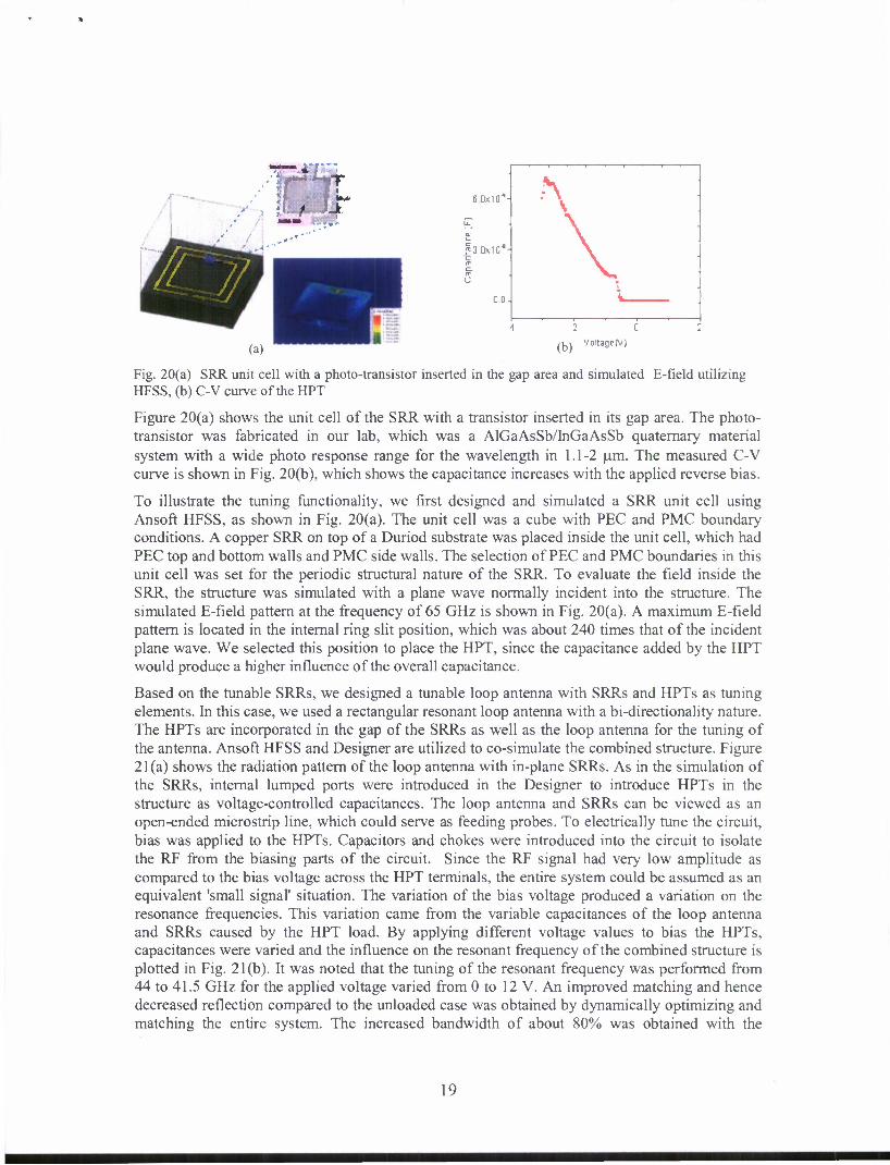
Fig. 20(a) SRR unit cell with a photo-transistor inserted in the gap area and simulated E-field utilizing HFSS, (b) C-V curve of the HPT
Figure 20(a) shows the unit cell of the SRR with a transistor inserted in its gap area. The photo- transistor was fabricated in our lab, which was a AlGaAsSb/InGaAsSb quaternary material system with a wide photo response range for the wavelength in 1.1-2 um. The measured C-V curve is shown in Fig. 20(b), which shows the capacitance increases with the applied reverse bias.
To illustrate the tuning functionality, we first designed and simulated a SRR unit cell using Ansoft HFSS, as shown in Fig. 20(a). The unit cell was a cube with PEC and PMC boundary conditions. A copper SRR on top of a Duriod substrate was placed inside the unit cell, which had PEC top and bottom walls and PMC side walls. The selection of PEC and PMC boundaries in this unit cell was set for the periodic structural nature of the SRR. To evaluate the field inside the SRR, the structure was simulated with a plane wave normally incident into the structure. The simulated E-field pattern at the frequency of 65 GHz is shown in Fig. 20(a). A maximum E-field pattern is located in the internal ring slit position, which was about 240 times that of the incident plane wave. We selected this position to place the HPT, since the capacitance added by the HPT would produce a higher influence of the overall capacitance.
Based on the tunable SRRs, we designed a tunable loop antenna with SRRs and HPTs as tuning elements. In this case, we used a rectangular resonant loop antenna with a bi-directionality nature. The HPTs are incorporated in the gap of the SRRs as well as the loop antenna for the tuning of the antenna. Ansoft HFSS and Designer are utilized to co-simulate the combined structure. Figure 21 (a) shows the radiation pattern of the loop antenna with in-plane SRRs. As in the simulation of the SRRs, internal lumped ports were introduced in the Designer to introduce HPTs in the structure as voltage-controlled capacitances. The loop antenna and SRRs can be viewed as an open-ended microstrip line, which could serve as feeding probes. To electrically tune the circuit, bias was applied to the HPTs. Capacitors and chokes were introduced into the circuit to isolate the RF from the biasing parts of the circuit. Since the RF signal had very low amplitude as compared to the bias voltage across the HPT terminals, the entire system could be assumed as an equivalent 'small signal' situation. The variation of the bias voltage produced a variation on the resonance frequencies. This variation came from the variable capacitances of the loop antenna and SRRs caused by the HPT load. By applying different voltage values to bias the HPTs, capacitances were varied and the influence on the resonant frequency of the combined structure is plotted in Fig. 21(b). It was noted that the tuning of the resonant frequency was performed from 44 to 41.5 GHz for the applied voltage varied from 0 to 12 V. An improved matching and hence decreased reflection compared to the unloaded case was obtained by dynamically optimizing and matching the entire system. The increased bandwidth of about 80% was obtained with the
19
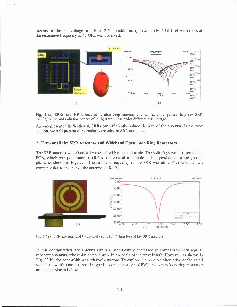
increase of the bias voltage from 0 to 12 V. In addition, approximately -60 dB reflection loss at the resonance frequency of 43 GHz was observed.
UM«NN MM
VfcjftfW
mm.
>•
-40.00-
-OC.0O
^-e=5S
//
«rsi i) —
An-t
F [OHi] «S"1 —
(a) (b)
Fig. 21(a) SRRs and HPTs enabled tunable loop antenna and its radiation pattern In-plane SRR Configuration and radiation pattern of it, (b) Return loss under different bias voltage
As was presented in Section 4, SRRs can efficiently reduce the size of the antenna. In the next section, we will present our simulation results on SRR antennas.
7. Ultra-small size SRR Antennas and Wideband Open Loop Ring Resonators
The SRR antenna was electrically excited with a coaxial cable. The split rings were patterns on a PCB, which was positioned parallel to the coaxial monopole and perpendicular to the ground plane, as shown in Fig. 22. The resonant frequency of the SRR was about 4.28 GHz, which corresponded to the size of the antenna of 0.1 XQ.
Anaofl Ctxporalion
4.50 4.60
Fig. 22 (a) SRR antenna feed by coaxial cable, (b) Return loss of the SRR antenna
In this configuration, the antenna size was significantly decreased in comparison with regular resonant antennas, whose dimensions were in the scale of the wavelength. However, as shown in Fig. 22(b), the bandwidth was relatively narrow. To explore the possible alternative of the small wide bandwidth antenna, we designed a coplanar wave (CPW) feed open-loop ring resonator antenna as shown below.
20
XYPIot8 HFSSDesignl
a-20.00-
~30 °iocT e.dd 8 do io7oo i2lbT" 14.00 16.00 ~HToo Freq [GHz]
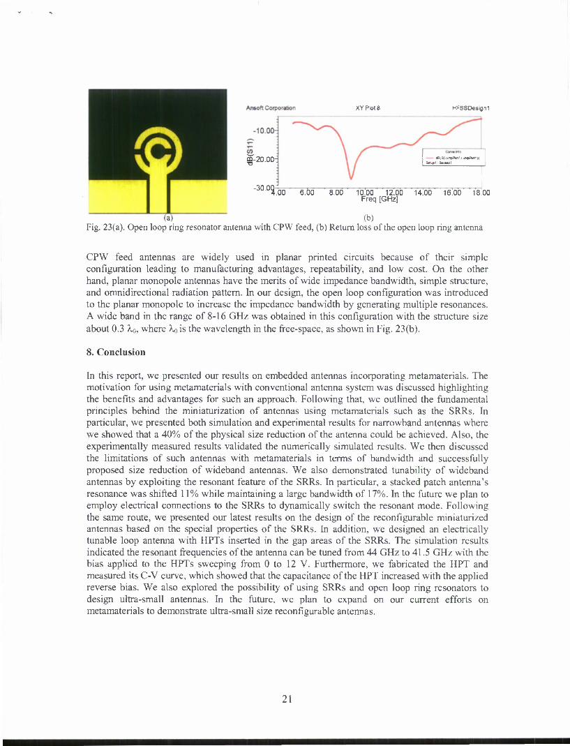
(a) (b) Fig. 23(a). Open loop ring resonator antenna with CPW feed, (b) Return loss of the open loop ring antenna
CPW feed antennas are widely used in planar printed circuits because of their simple configuration leading to manufacturing advantages, repeatability, and low cost. On the other hand, planar monopole antennas have the merits of wide impedance bandwidth, simple structure, and omnidirectional radiation pattern. In our design, the open loop configuration was introduced to the planar monopole to increase the impedance bandwidth by generating multiple resonances. A wide band in the range of 8-16 GHz was obtained in this configuration with the structure size about 0.3 Xo, where A.0 is the wavelength in the free-space, as shown in Fig. 23(b).
8. Conclusion
In this report, we presented our results on embedded antennas incorporating metamaterials. The motivation for using metamaterials with conventional antenna system was discussed highlighting the benefits and advantages for such an approach. Following that, we outlined the fundamental principles behind the miniaturization of antennas using metamaterials such as the SRRs. In particular, we presented both simulation and experimental results for narrowband antennas where we showed that a 40% of the physical size reduction of the antenna could be achieved. Also, the experimentally measured results validated the numerically simulated results. We then discussed the limitations of such antennas with metamaterials in terms of bandwidth and successfully proposed size reduction of wideband antennas. We also demonstrated tunability of wideband antennas by exploiting the resonant feature of the SRRs. In particular, a stacked patch antenna's resonance was shifted 11% while maintaining a large bandwidth of 17%. In the future we plan to employ electrical connections to the SRRs to dynamically switch the resonant mode. Following the same route, we presented our latest results on the design of the reconfigurable miniaturized antennas based on the special properties of the SRRs. In addition, we designed an electrically tunable loop antenna with HPTs inserted in the gap areas of the SRRs. The simulation results indicated the resonant frequencies of the antenna can be tuned from 44 GHz to 41.5 GHz with the bias applied to the HPTs sweeping from 0 to 12 V. Furthermore, we fabricated the HPT and measured its C-V curve, which showed that the capacitance of the HPT increased with the applied reverse bias. We also explored the possibility of using SRRs and open loop ring resonators to design ultra-small antennas. In the future, we plan to expand on our current efforts on metamaterials to demonstrate ultra-small size reconfigurable antennas.
21

9. References:
[I] C. Lin, I. O. Mirza, S. Shi and D. W. Prather , "A Correlator Sensor Chip Based on the Integration of Meta-materials and Photonic Crystals," IEEE MTT Symposium, Atlanta, Georgia, USA 2008. [2] I. O. Mirza, S. Shi. C. Fazi. D. W. Prather, "Stacked Patch Antenna Miniaturization Using Metamaterials," IEEE Antennas And Propagation and USNC/URSI National Radio Science Meeting, San Diego, 2008. [3] Zhaolin Lu, Binglin Miao, Timothy R. Hodson, C. Lin, Janusz A. Murakowski, and Dennis W. Prather, "Negative refraction imaging in a hybrid photonic crystal device at near-infrared frequencies," Optics Express, 15(3), 1286 (2007) [4] I. O. Mirza, S. Shi, C. Fazi, J. Mait and D. W. Prather, "A Study of Loop Antenna Miniaturization Using Split Ring Resonators," IEEE AP-S Conference, Hawaii, June 2007. [5] C. Fazi, S. Shi, I. O Mirza, D. W. Prather, "Split ring resonator slab modeling for a metamaterial loaded loop antenna," Applied Computational Electromagnetics Society Conference, Verona, Italy. (2007). [6] P. M. T. Ikonen, S. I. Maslovski, C. R. Simovski and S. A. Tretyakov, "On artificial magnetodielectric loading for improving the impedance bandwidth properties of microstrip antennas," IEEE Transactions on Antennas and Propagation, Vol. 54, pp. 1654-1662, 2006. [7] M. Karkkakainen and P. Ikonen, "Patch Antenna with Stacked Split-Ring Resonators as an Artificial Magneto-Dielectric Material," Microwave and Optical Technology Letters, Vol. 46, pp.554-556, 2005. [8] I. Mirza, S. Shi, J. Mait, C. Fazi, D. Prather, "Miniaturized Antennas for Compact Soldier Combat Systems," Proc. 25th Army Science Conference, Orlando, FL, 2006. [9] I. Mirza, S. Shi, D. W. Prather, "Calculation of the Dispersion Diagrams of LHM Using the 3D-FDTD Method," Microwave and Optical Technology Letters, Vol. 45, pp. 394-397, 2005. [10] F. Croq and D. Pozar, "Millimeter-Wave Design of Wideband-Band Aperture-Coupled Stacked Microstrip Antennas," IEEE Transactions on Antennas and Propagation, Vol. 39, pp. 1770-1776, 1991. [II] S. Oh, L. Shafai, "Artificial Magnetic Conductor Using Split Ring Resonators And Its Applications To Antennas", Microwave and Optical Technology Letters, Vol. 48, pp. 329-334, 2006. [12] Z. Chen, M. Chia, Broadband Planar Antennas, John Wiley & Sons. Press., 2006. [13] R.C. Hansen, M. Burke, "Antenna With Magneto-Dielectrics," Microwave and Optical Technology Letters, Vol. 26, pp. 75-78, 2000.
22


