Embed Size (px)
Citation preview
E-1
INSTALLATION MANUAL/
A3PE-9620-001BS0830301
I. Outline of installation procedures
When installing the machine and associated options as a system, follow the order shown on the upper.Caution: • For the detailed installation procedures for each option, follow the instructions given in the corresponding
installation manual and perform the procedures correctly. (Optional devices must be installed after com-pleting the main body installation.)
• Once the Power Switch is turned ON, do not turn OFF it until the installation work has been completed. • Lifting the machine in an awkward position or transporting it in a poorly balanced position could result in
personal injury. When transporting the machine, assign an adequate number of persons to the job and ensure that each person can take a good position of not being excessively loaded. <Machine mass> OC-512 and MB-505 included as standard: Approx. 29 kg (63-15/16 lb)
OC-512 or MB-505 included as standard: Approx. 27.5 kg (60-5/8 lb)OC-512 and MB-505 not included as standard: Approx. 26 kg (57-5/16 lb)
*OC-512: Original Cover MB-505: Multi Bypass Tray
Electronic system options
✱ Electronic system options
Machine
MC-504*
*: Varies depending on each model/applicable marketing area
DK-706* DK-707*PF-507 DK-708*
OC-512*DF-625
MB-505*
AD-509
IC-209 NC-504FK-510
MK-733
A3PEIXC001DA
Applied Machines: /
E-2
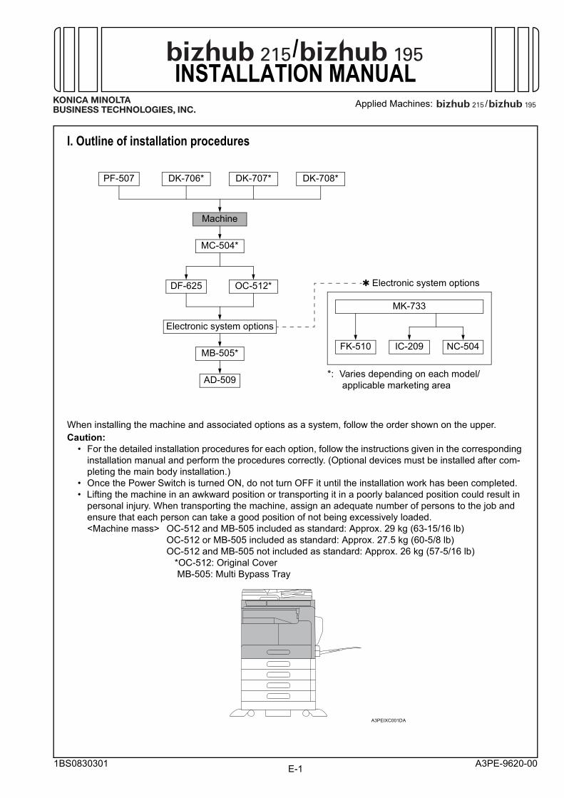
II. Installation space (unit: mm (inch))bizhub 215 + DF-625 + PF-507 + DK-708
III. Pre-installation check items1. Install the machine at a horizontal and stable
place.2. Be sure to use a power source of the voltage and
frequency indicated in the product specifications. Ensure that the current carrying capacity of the power outlet is at least equal to the current listed in the product specifications.
3. Power the machine directly from a dedicated power outlet. (Do not use an extension cord.)
4. Do not plug or unplug the power cord with wet or dirty hands, otherwise you may get an electric shock.
5. Avoid a hot and humid environment, or a place exposed to direct sunlight.
6. Avoid a dusty location, or a place near volatile and flammable substances.
7. Avoid a poorly ventilated place.
IV. Accessory parts
* Varies depending on the applicable marketing area
Note:This manual provides the illustrations of the acces-sory parts and machine that may be slightly differ-ent in shape from yours. In that case, instead of the illustrations, use the appearance of your machine to follow the installation procedure. This does not cause any significant change or problem with the procedure.
A3PEIXC002DA
1109 (43-11/16)
570 (22-7/16) 429 (16-7/8)
1038 (40-7/8)
1388
(54-
5/8)
358 (14-1/8)
No. Name Q’ty
1. Quick guide * 12. Installation manual (this manual) 13. User’s guide CD * 14. Developer 15. Power cord * 16. Power cord instruction * 17. CD-ROM * 1 set8. Label (Legal restrictions on copying) * 1
After unpacking, be sure to get rid of the packaging materials and keep them out of the reach of children.Putting the head in the plastic bag involves danger of suffocation.
E-3
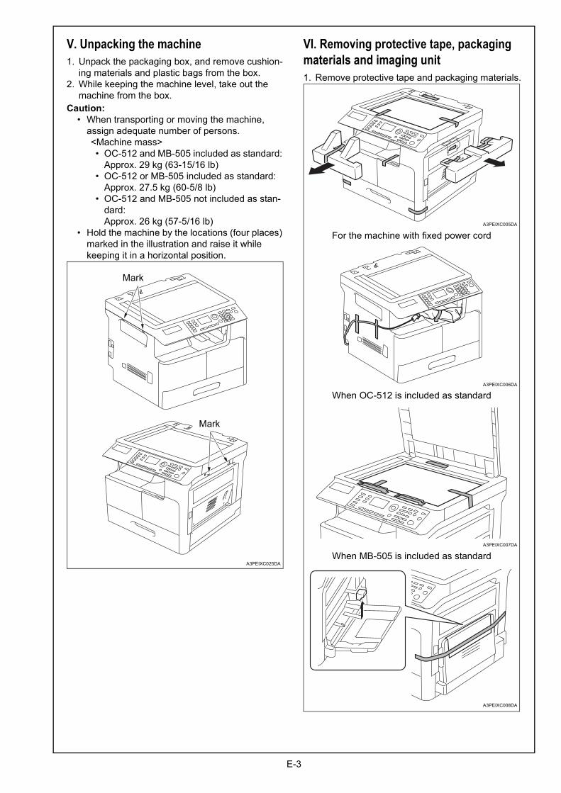
V. Unpacking the machine1. Unpack the packaging box, and remove cushion-
ing materials and plastic bags from the box.2. While keeping the machine level, take out the
machine from the box.Caution: • When transporting or moving the machine,
assign adequate number of persons.<Machine mass>
• OC-512 and MB-505 included as standard: Approx. 29 kg (63-15/16 lb)
• OC-512 or MB-505 included as standard: Approx. 27.5 kg (60-5/8 lb)
• OC-512 and MB-505 not included as stan-dard: Approx. 26 kg (57-5/16 lb)
• Hold the machine by the locations (four places) marked in the illustration and raise it while keeping it in a horizontal position.
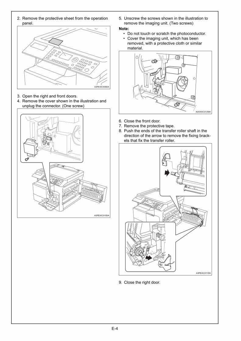
VI. Removing protective tape, packaging materials and imaging unit1. Remove protective tape and packaging materials.
A3PEIXC025DA
Mark
Mark
When OC-512 is included as standard
When MB-505 is included as standard
A3PEIXC006DA
A3PEIXC007DA
A3PEIXC008DA
A3PEIXC005DA
For the machine with fixed power cord
E-4
2. Remove the protective sheet from the operation panel.
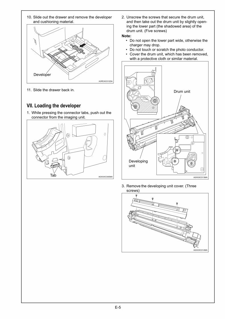
3. Open the right and front doors.4. Remove the cover shown in the illustration and
unplug the connector. (One screw)
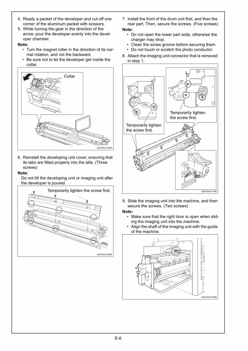
5. Unscrew the screws shown in the illustration to remove the imaging unit. (Two screws)
Note: • Do not touch or scratch the photoconductor. • Cover the imaging unit, which has been
removed, with a protective cloth or similar material.
6. Close the front door.7. Remove the protective tape.8. Push the ends of the transfer roller shaft in the
direction of the arrow to remove the fixing brack-ets that fix the transfer roller.
9. Close the right door.
A3PEIXC009DA
A3PEIXC010DA
A0XXIXC012MA
A3PEIXC011DA
E-5
10. Slide out the drawer and remove the developer and cushioning material.
11. Slide the drawer back in.
VII. Loading the developer1. While pressing the connector tabs, push out the
connector from the imaging unit.
2. Unscrew the screws that secure the drum unit, and then take out the drum unit by slightly open-ing the lower part (the shadowed area) of the drum unit. (Five screws)
Note: • Do not open the lower part wide, otherwise the
charger may drop. • Do not touch or scratch the photo conductor. • Cover the drum unit, which has been removed,
with a protective cloth or similar material.
3. Remove the developing unit cover. (Three screws)
A3PEIXC012DA
Developer
A0XXIXC040MATabA0XXIXC013MA
Drum unit
Developing unit
A0XXIXC014MA
E-6
4. Ready a packet of the developer and cut off one corner of the aluminum packet with scissors.
5. While turning the gear in the direction of the arrow, pour the developer evenly into the devel-oper chamber.
Note: • Turn the magnet roller in the direction of its nor-
mal rotation, and not the backward. • Be sure not to let the developer get inside the
collar.
6. Reinstall the developing unit cover, ensuring that its tabs are fitted properly into the slits. (Three screws)
Note:Do not tilt the developing unit or imaging unit after the developer is poured.
7. Install the front of the drum unit first, and then the rear part. Then, secure the screws. (Five screws)
Note: • Do not open the lower part wide, otherwise the
charger may drop. • Clean the screw groove before securing them. • Do not touch or scratch the photo conductor.8. Attach the imaging unit connector that is removed
in step 1.
9. Slide the imaging unit into the machine, and then secure the screws. (Two screws)
Note: • Make sure that the right door is open when slid-
ing the imaging unit into the machine. • Align the shaft of the imaging unit with the guide
of the machine.
A0XXIXC015MA
Collar
A0XXIXC016MA
Temporarily tighten the screw first. A0XXIXC017MA
Temporarily tighten the screw first.
Temporarily tighten the screw first.
A0XXIXC019MA
E-7
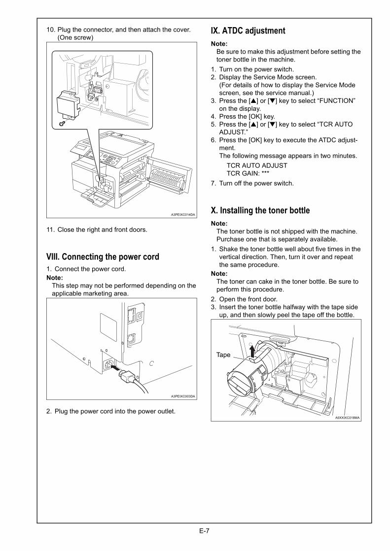
10. Plug the connector, and then attach the cover. (One screw)
11. Close the right and front doors.
VIII. Connecting the power cord1. Connect the power cord.Note:
This step may not be performed depending on the applicable marketing area.
2. Plug the power cord into the power outlet.
IX. ATDC adjustmentNote:
Be sure to make this adjustment before setting the toner bottle in the machine.
1. Turn on the power switch.2. Display the Service Mode screen.
(For details of how to display the Service Mode screen, see the service manual.)
3. Press the [▲] or [▼] key to select “FUNCTION” on the display.
4. Press the [OK] key.5. Press the [▲] or [▼] key to select “TCR AUTO
ADJUST.”6. Press the [OK] key to execute the ATDC adjust-
ment.The following message appears in two minutes.
TCR AUTO ADJUSTTCR GAIN: ***
7. Turn off the power switch.
X. Installing the toner bottleNote:
The toner bottle is not shipped with the machine. Purchase one that is separately available.
1. Shake the toner bottle well about five times in the vertical direction. Then, turn it over and repeat the same procedure.
Note:The toner can cake in the toner bottle. Be sure to perform this procedure.
2. Open the front door.3. Insert the toner bottle halfway with the tape side
up, and then slowly peel the tape off the bottle.
A3PEIXC014DA
A3PEIXC003DA
A0XXIXC018MA
Tape
E-8
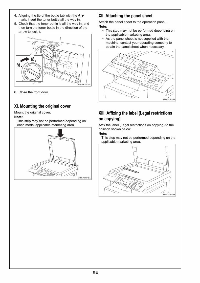
4. Aligning the tip of the bottle tab with the mark, insert the toner bottle all the way in.
5. Check that the toner bottle is all the way in, and then turn the toner bottle in the direction of the arrow to lock it.
6. Close the front door.
XI. Mounting the original coverMount the original cover.Note:
This step may not be performed depending on each model/applicable marketing area.
XII. Attaching the panel sheetAttach the panel sheet to the operation panel.Note: • This step may not be performed depending on
the applicable marketing area. • As the panel sheet is not supplied with the
machine, contact your operating company to obtain the panel sheet when necessary.
XIII. Affixing the label (Legal restrictions on copying)Affix the label (Legal restrictions on copying) to the position shown below.Note:
This step may not be performed depending on the applicable marketing area.
A0XXIXC050MA
A3PEIXC004DA
A3PEIXC013DA
A3PEIXC024DA