Embed Size (px)
Citation preview
FANs 216, 125, 195Product/Technical Bulletin A319
Issue Date 0396
© 1996 Johnson Controls, Inc. 1Part No. 24-7664-257, Rev. GCode No. LIT-216010
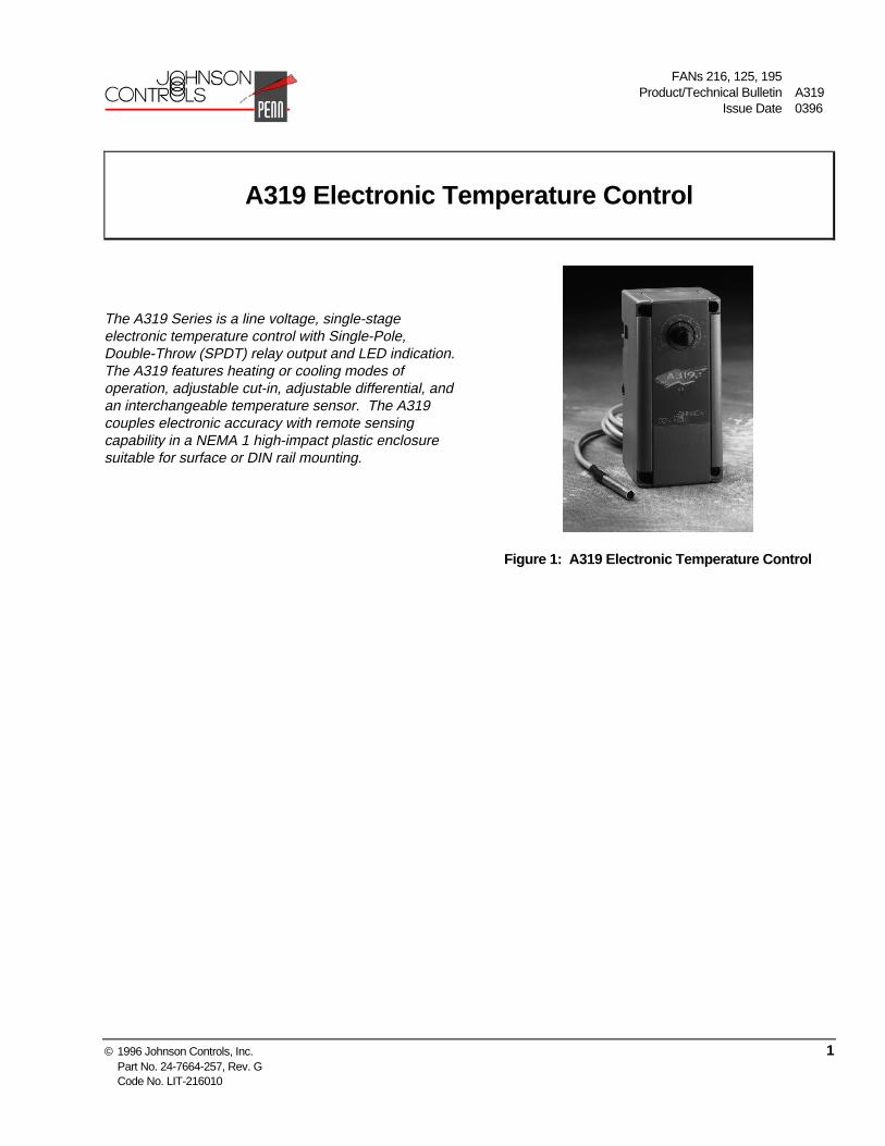
The A319 Series is a line voltage, single-stageelectronic temperature control with Single-Pole,Double-Throw (SPDT) relay output and LED indication.The A319 features heating or cooling modes ofoperation, adjustable cut-in, adjustable differential, andan interchangeable temperature sensor. The A319couples electronic accuracy with remote sensingcapability in a NEMA 1 high-impact plastic enclosuresuitable for surface or DIN rail mounting.
Figure 1: A319 Electronic Temperature Control
A319 Electronic Temperature Control
FANs 216, 125, 195Product/Technical Bulletin A319
Issue Date 0396
© 1996 Johnson Controls, Inc. 2Part No. 24-7664-257, Rev. GCode No. LIT-216010
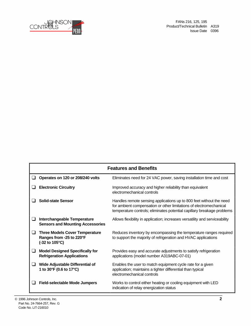
Features and Benefits
❑ Operates on 120 or 208/240 volts Eliminates need for 24 VAC power, saving installation time and cost
❑ Electronic Circuitry Improved accuracy and higher reliability than equivalentelectromechanical controls
❑ Solid-state Sensor Handles remote sensing applications up to 800 feet without the needfor ambient compensation or other limitations of electromechanicaltemperature controls; eliminates potential capillary breakage problems
❑ Interchangeable TemperatureSensors and Mounting Accessories
Allows flexibility in application; increases versatility and serviceability
❑ Three Models Cover TemperatureRanges from -25 to 220°F(-32 to 105°C)
Reduces inventory by encompassing the temperature ranges requiredto support the majority of refrigeration and HVAC applications
❑ Model Designed Specifically forRefrigeration Applications
Provides easy and accurate adjustments to satisfy refrigerationapplications (model number A319ABC-07-01)
❑ Wide Adjustable Differential of1 to 30°F (0.6 to 17°C)
Enables the user to match equipment cycle rate for a givenapplication; maintains a tighter differential than typicalelectromechanical controls
❑ Field-selectable Mode Jumpers Works to control either heating or cooling equipment with LEDindication of relay energization status
A319 Electronic Temperature Control Product/Technical Bulletin 3
Application Overview
The A319 can be used to control a wide variety ofsingle-stage refrigeration or HVAC equipment.Typical applications include:
● frozen/refrigerated food cases
● compressor lockout (disables compressor whentemperature exceeds limits)
● beverage/milk coolers
● condenser fan cycling
● boiler control
● pump control (cooling towers)
● space and return air temperature control
● immersion sensing for actuation of hot water andsteam valves in heating applications (wellrequired)
Refer to Figures 5 and 6 for typical wiring diagrams.
Operation
IMPORTANT: All A319 Series Controls aredesigned for use only asoperating controls. Where anoperating control failure wouldresult in personal injury and/orloss of property, it is theresponsibility of the installer toadd devices (safety, limitcontrols) that protect against,or systems (alarm, supervisorysystems) that warn of controlfailure.
The A319 Temperature Control operates on 120 or208/240 VAC; 50/60 Hz and supplies a SPDT relayoutput. A front panel LED indicates “ON” when therelay is energized (which closes the N.O. contacts).Adjustable features include:
● cut-in
● differential
● heating/cooling mode
Definitions
Cut-in: The point at which the N.O. (NormallyOpen) contact closes. Equal to the dialsetting of the A319.
Cut-out: The point at which the N.O. contactopens.
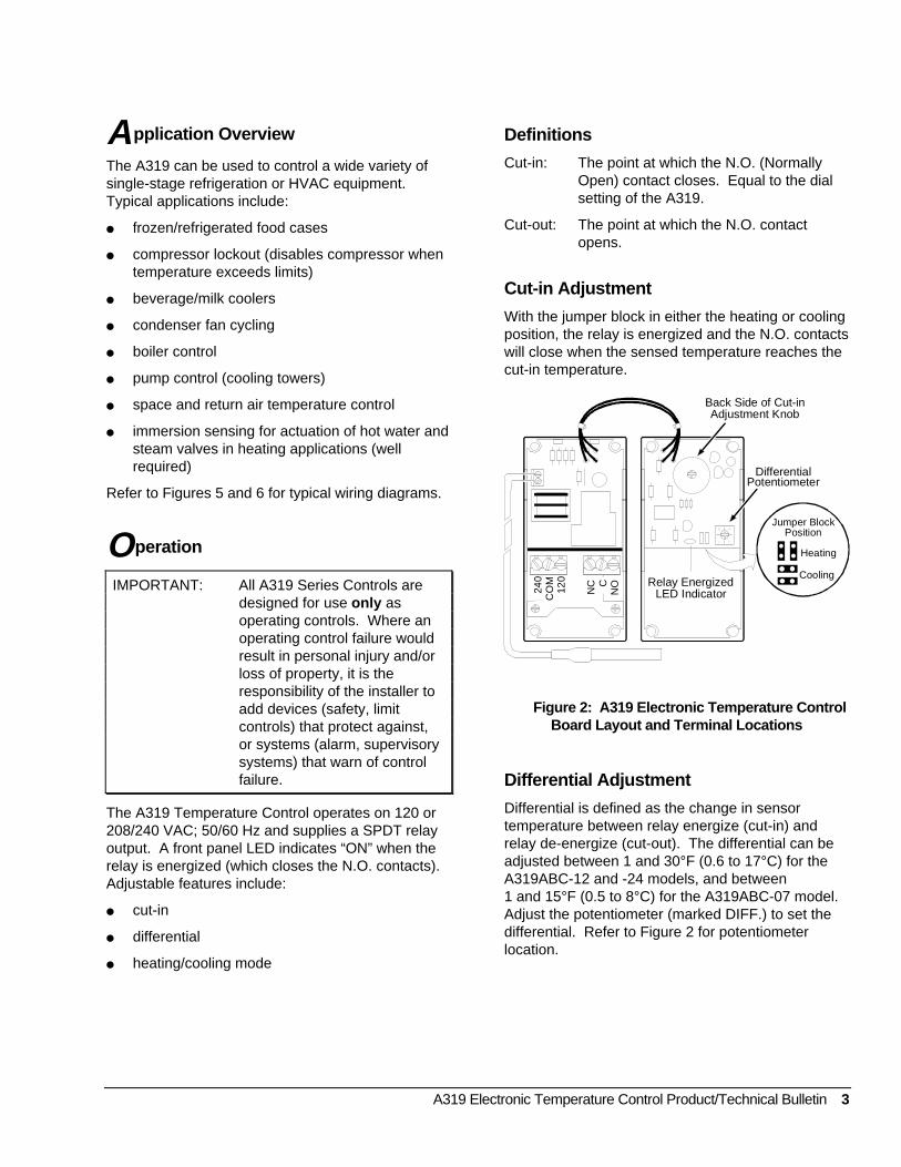
Cut-in Adjustment
With the jumper block in either the heating or coolingposition, the relay is energized and the N.O. contactswill close when the sensed temperature reaches thecut-in temperature.
NC C
NO24
0C
OM
120 Relay Energized
LED Indicator
Back Side of Cut-inAdjustment Knob
DifferentialPotentiometer
Jumper BlockPosition
Heating
Cooling
Figure 2: A319 Electronic Temperature ControlBoard Layout and Terminal Locations
Differential Adjustment
Differential is defined as the change in sensortemperature between relay energize (cut-in) andrelay de-energize (cut-out). The differential can beadjusted between 1 and 30°F (0.6 to 17°C) for theA319ABC-12 and -24 models, and between1 and 15°F (0.5 to 8°C) for the A319ABC-07 model.Adjust the potentiometer (marked DIFF.) to set thedifferential. Refer to Figure 2 for potentiometerlocation.
4 A319 Electronic Temperature Control Product/Technical Bulletin
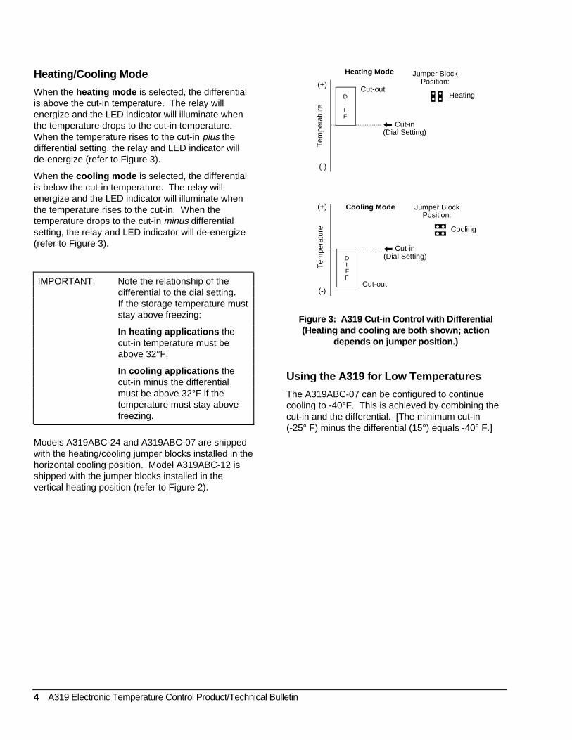
Heating/Cooling Mode
When the heating mode is selected, the differentialis above the cut-in temperature. The relay willenergize and the LED indicator will illuminate whenthe temperature drops to the cut-in temperature.When the temperature rises to the cut-in plus thedifferential setting, the relay and LED indicator willde-energize (refer to Figure 3).
When the cooling mode is selected, the differentialis below the cut-in temperature. The relay willenergize and the LED indicator will illuminate whenthe temperature rises to the cut-in. When thetemperature drops to the cut-in minus differentialsetting, the relay and LED indicator will de-energize(refer to Figure 3).
IMPORTANT: Note the relationship of thedifferential to the dial setting.If the storage temperature muststay above freezing:
In heating applications thecut-in temperature must beabove 32°F.
In cooling applications thecut-in minus the differentialmust be above 32°F if thetemperature must stay abovefreezing.
Models A319ABC-24 and A319ABC-07 are shippedwith the heating/cooling jumper blocks installed in thehorizontal cooling position. Model A319ABC-12 isshipped with the jumper blocks installed in thevertical heating position (refer to Figure 2).
(+)
(-)
Tem
pera
ture
Jumper BlockPosition:
Cooling
Cut-in(Dial Setting)
(+)
(-)
Tem
pera
ture
Jumper BlockPosition:
Heating
Cut-in(Dial Setting)
DIFF
Cut-out
DIFF
Cut-out
Cooling Mode
Heating Mode
Figure 3: A319 Cut-in Control with Differential(Heating and cooling are both shown; action
depends on jumper position.)
Using the A319 for Low Temperatures
The A319ABC-07 can be configured to continuecooling to -40°F. This is achieved by combining thecut-in and the differential. [The minimum cut-in(-25° F) minus the differential (15°) equals -40° F.]
A319 Electronic Temperature Control Product/Technical Bulletin 5
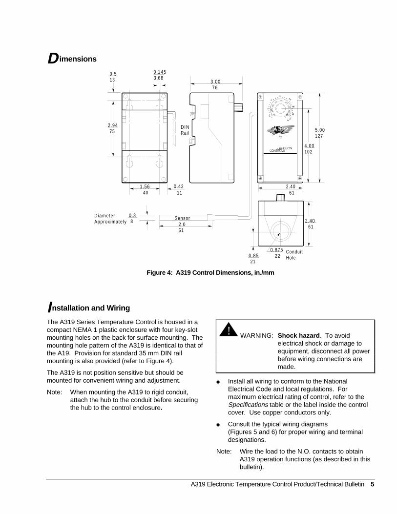
Dimensions
4050
6 0
708 0
105
100
115
1 30
14 5160
175
1902
05
0 .513
2.94 75
1.56 40
0.42 11
DINRail
3 .00 76
2.40 61
2.40 61
0.875 22
Condui tHole0.85
21
Sensor2.051
5.00127
4.00102
DiameterApproximately
0.3 8
0 .1 4 53 .68
Figure 4: A319 Control Dimensions, in./mm
Installation and Wiring
The A319 Series Temperature Control is housed in acompact NEMA 1 plastic enclosure with four key-slotmounting holes on the back for surface mounting. Themounting hole pattern of the A319 is identical to that ofthe A19. Provision for standard 35 mm DIN railmounting is also provided (refer to Figure 4).
The A319 is not position sensitive but should bemounted for convenient wiring and adjustment.
Note: When mounting the A319 to rigid conduit,attach the hub to the conduit before securingthe hub to the control enclosure.
! WARNING: Shock hazard . To avoidelectrical shock or damage toequipment, disconnect all powerbefore wiring connections aremade.
● Install all wiring to conform to the NationalElectrical Code and local regulations. Formaximum electrical rating of control, refer to theSpecifications table or the label inside the controlcover. Use copper conductors only.
● Consult the typical wiring diagrams(Figures 5 and 6) for proper wiring and terminaldesignations.
Note: Wire the load to the N.O. contacts to obtainA319 operation functions (as described in thisbulletin).
6 A319 Electronic Temperature Control Product/Technical Bulletin
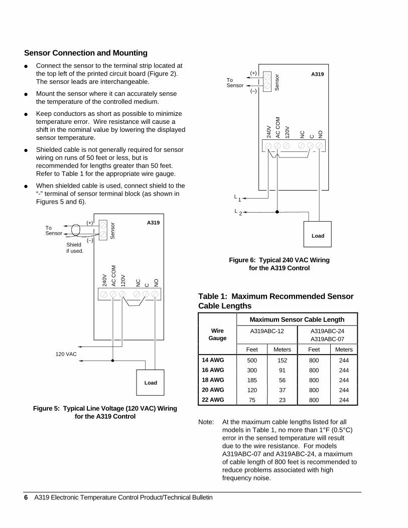
Sensor Connection and Mounting
● Connect the sensor to the terminal strip located atthe top left of the printed circuit board (Figure 2).The sensor leads are interchangeable.
● Mount the sensor where it can accurately sensethe temperature of the controlled medium.
● Keep conductors as short as possible to minimizetemperature error. Wire resistance will cause ashift in the nominal value by lowering the displayedsensor temperature.
● Shielded cable is not generally required for sensorwiring on runs of 50 feet or less, but isrecommended for lengths greater than 50 feet.Refer to Table 1 for the appropriate wire gauge.
● When shielded cable is used, connect shield to the“-” terminal of sensor terminal block (as shown inFigures 5 and 6).
240V
AC
CO
M
120V
NC
C NO
To Sensor
A319
Sen
sor(+)
(–)
120 VAC
Shieldif used.
Load
Figure 5: Typical Line Voltage (120 VAC) Wiringfor the A319 Control
240V
AC
CO
M
120V
NC
C NO
L 1
L 2
To Sensor
A319
Sen
sor(+)
(–)
Load
Figure 6: Typical 240 VAC Wiringfor the A319 Control
Table 1: Maximum Recommended SensorCable Lengths
Maximum Sensor Cable Length
WireGauge
A319ABC-12 A319ABC-24A319ABC-07
Feet Meters Feet Meters
14 AWG 500 152 800 244
16 AWG 300 91 800 244
18 AWG 185 56 800 244
20 AWG 120 37 800 244
22 AWG 75 23 800 244
Note: At the maximum cable lengths listed for allmodels in Table 1, no more than 1°F (0.5°C)error in the sensed temperature will resultdue to the wire resistance. For modelsA319ABC-07 and A319ABC-24, a maximumof cable length of 800 feet is recommended toreduce problems associated with highfrequency noise.
A319 Electronic Temperature Control Product/Technical Bulletin 7
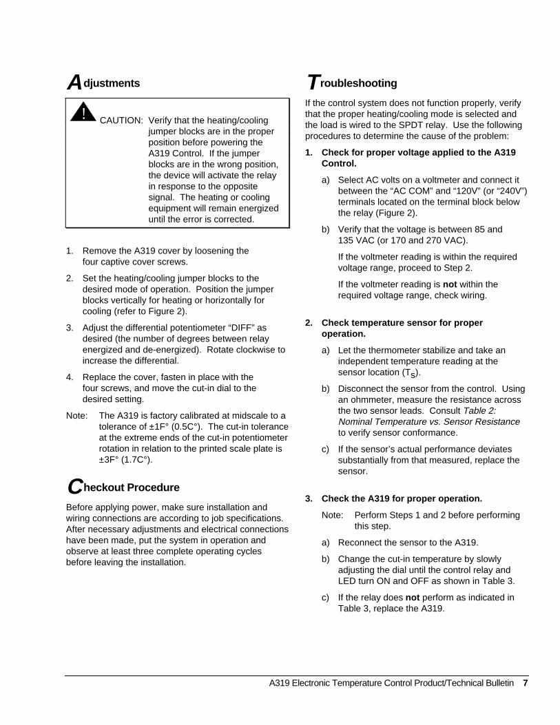
A djustments
! CAUTION: Verify that the heating/coolingjumper blocks are in the properposition before powering theA319 Control. If the jumperblocks are in the wrong position,the device will activate the relayin response to the oppositesignal. The heating or coolingequipment will remain energizeduntil the error is corrected.
1. Remove the A319 cover by loosening thefour captive cover screws.
2. Set the heating/cooling jumper blocks to thedesired mode of operation. Position the jumperblocks vertically for heating or horizontally forcooling (refer to Figure 2).
3. Adjust the differential potentiometer “DIFF” asdesired (the number of degrees between relayenergized and de-energized). Rotate clockwise toincrease the differential.
4. Replace the cover, fasten in place with thefour screws, and move the cut-in dial to thedesired setting.
Note: The A319 is factory calibrated at midscale to atolerance of ±1F° (0.5C°). The cut-in toleranceat the extreme ends of the cut-in potentiometerrotation in relation to the printed scale plate is±3F° (1.7C°).
Checkout Procedure
Before applying power, make sure installation andwiring connections are according to job specifications.After necessary adjustments and electrical connectionshave been made, put the system in operation andobserve at least three complete operating cyclesbefore leaving the installation.
Troubleshooting
If the control system does not function properly, verifythat the proper heating/cooling mode is selected andthe load is wired to the SPDT relay. Use the followingprocedures to determine the cause of the problem:
1. Check for proper voltage applied to the A319Control.
a) Select AC volts on a voltmeter and connect itbetween the “AC COM” and “120V” (or “240V”)terminals located on the terminal block belowthe relay (Figure 2).
b) Verify that the voltage is between 85 and135 VAC (or 170 and 270 VAC).
If the voltmeter reading is within the requiredvoltage range, proceed to Step 2.
If the voltmeter reading is not within therequired voltage range, check wiring.
2. Check temperature sensor for properoperation.
a) Let the thermometer stabilize and take anindependent temperature reading at thesensor location (Ts).
b) Disconnect the sensor from the control. Usingan ohmmeter, measure the resistance acrossthe two sensor leads. Consult Table 2:Nominal Temperature vs. Sensor Resistanceto verify sensor conformance.
c) If the sensor’s actual performance deviatessubstantially from that measured, replace thesensor.
3. Check the A319 for proper operation.
Note: Perform Steps 1 and 2 before performingthis step.
a) Reconnect the sensor to the A319.
b) Change the cut-in temperature by slowlyadjusting the dial until the control relay andLED turn ON and OFF as shown in Table 3.
c) If the relay does not perform as indicated inTable 3, replace the A319.
8 A319 Electronic Temperature Control Product/Technical Bulletin
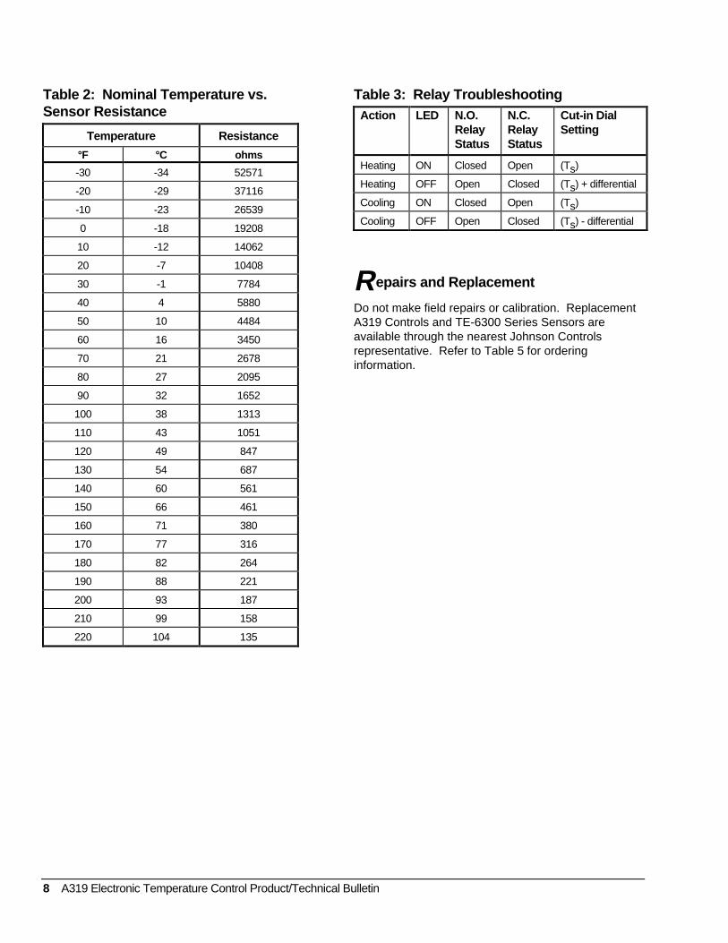
Table 2: Nominal Temperature vs.Sensor Resistance
Temperature Resistance
°F °C ohms
-30 -34 52571
-20 -29 37116
-10 -23 26539
0 -18 19208
10 -12 14062
20 -7 10408
30 -1 7784
40 4 5880
50 10 4484
60 16 3450
70 21 2678
80 27 2095
90 32 1652
100 38 1313
110 43 1051
120 49 847
130 54 687
140 60 561
150 66 461
160 71 380
170 77 316
180 82 264
190 88 221
200 93 187
210 99 158
220 104 135
Table 3: Relay TroubleshootingAction LED N.O.
RelayStatus
N.C.RelayStatus
Cut-in DialSetting
Heating ON Closed Open (Ts)
Heating OFF Open Closed (Ts) + differential
Cooling ON Closed Open (Ts)
Cooling OFF Open Closed (Ts) - differential
Repairs and Replacement
Do not make field repairs or calibration. ReplacementA319 Controls and TE-6300 Series Sensors areavailable through the nearest Johnson Controlsrepresentative. Refer to Table 5 for orderinginformation.
A319 Electronic Temperature Control Product/Technical Bulletin 9
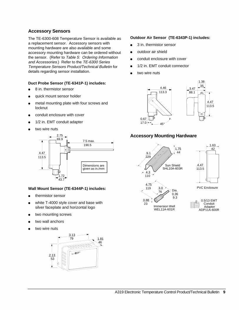
Accessory Sensors
The TE-6300-608 Temperature Sensor is available asa replacement sensor. Accessory sensors withmounting hardware are also available and someaccessory mounting hardware can be ordered withoutthe sensor. (Refer to Table 5: Ordering Informationand Accessories.) Refer to the TE-6300 SeriesTemperature Sensors Product/Technical Bulletin fordetails regarding sensor installation.
Duct Probe Sensor (TE-6341P-1) includes:
● 8 in. thermistor sensor
● quick mount sensor holder
● metal mounting plate with four screws andlocknut
● conduit enclosure with cover
● 1/2 in. EMT conduit adapter
● two wire nuts
Dimensions are given as in./mm
2.7569.9
7.5 max. 190.5
4.47113.5
1.7243.7
Wall Mount Sensor (TE-6344P-1) includes:
● thermistor sensor
● white T-4000 style cover and base withsilver faceplate and horizontal logo
● two mounting screws
● two wall anchors
● two wire nuts
3.13 79 1.81
46
2.13 53
Outdoor Air Sensor (TE-6343P-1) includes:
● 3 in. thermistor sensor
● outdoor air shield
● conduit enclosure with cover
● 1/2 in. EMT conduit connector
● two wire nuts
4.46113.3
0.6717.0 45°
3.4788.1
1.38 35
4.47113.5
Accessory Mounting Hardware
3.076
Sun ShieldSHL10A-603R
PVC Enclosure
Immersion WellWEL11A-601R
0.5/13 EMT Conduit Adapter
ADP11A-600R
9.1229
1.75 44
4.3110
Dia.0.36 9.3
4.75119
0.88 23
4.47113.5
1.63 42
10 A319 Electronic Temperature Control Product/Technical Bulletin
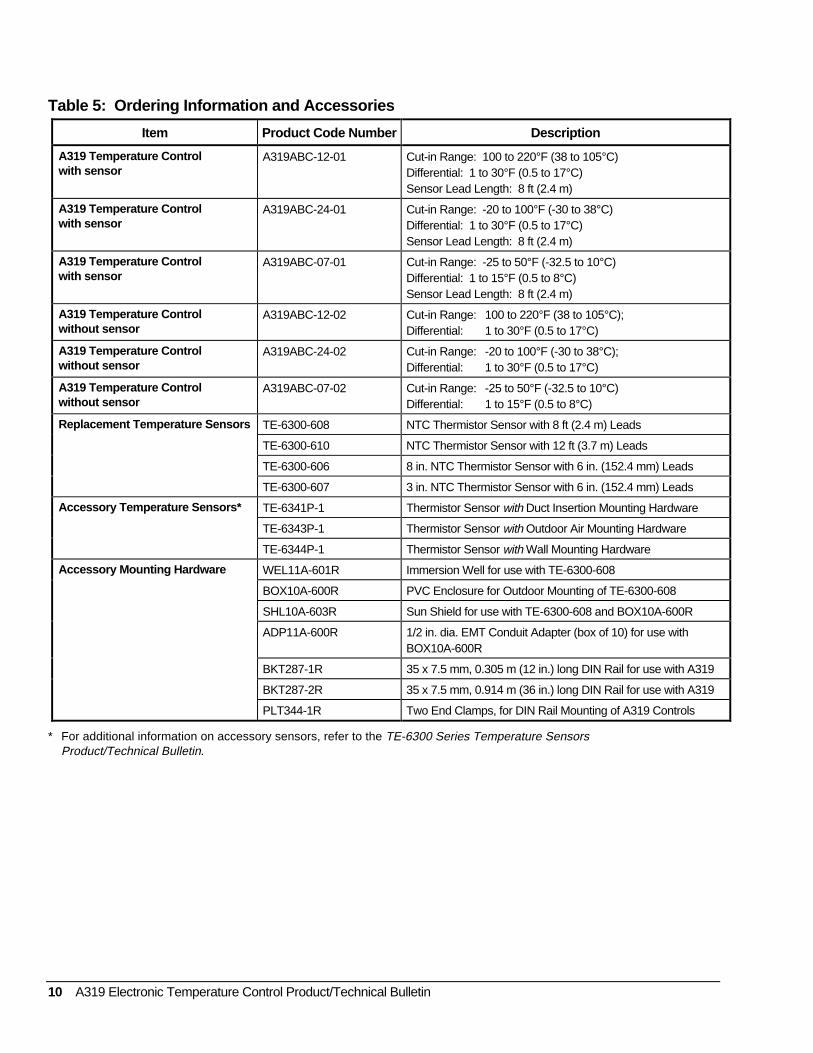
Table 5: Ordering Information and Accessories
Item Product Code Number Description
A319 Temperature Controlwith sensor
A319ABC-12-01 Cut-in Range: 100 to 220°F (38 to 105°C)Differential: 1 to 30°F (0.5 to 17°C)Sensor Lead Length: 8 ft (2.4 m)
A319 Temperature Controlwith sensor
A319ABC-24-01 Cut-in Range: -20 to 100°F (-30 to 38°C)Differential: 1 to 30°F (0.5 to 17°C)Sensor Lead Length: 8 ft (2.4 m)
A319 Temperature Controlwith sensor
A319ABC-07-01 Cut-in Range: -25 to 50°F (-32.5 to 10°C)Differential: 1 to 15°F (0.5 to 8°C)Sensor Lead Length: 8 ft (2.4 m)
A319 Temperature Controlwithout sensor
A319ABC-12-02 Cut-in Range: 100 to 220°F (38 to 105°C);Differential: 1 to 30°F (0.5 to 17°C)
A319 Temperature Controlwithout sensor
A319ABC-24-02 Cut-in Range: -20 to 100°F (-30 to 38°C);Differential: 1 to 30°F (0.5 to 17°C)
A319 Temperature Controlwithout sensor
A319ABC-07-02 Cut-in Range: -25 to 50°F (-32.5 to 10°C)Differential: 1 to 15°F (0.5 to 8°C)
Replacement Temperature Sensors TE-6300-608 NTC Thermistor Sensor with 8 ft (2.4 m) Leads
TE-6300-610 NTC Thermistor Sensor with 12 ft (3.7 m) Leads
TE-6300-606 8 in. NTC Thermistor Sensor with 6 in. (152.4 mm) Leads
TE-6300-607 3 in. NTC Thermistor Sensor with 6 in. (152.4 mm) Leads
Accessory Temperature Sensors* TE-6341P-1 Thermistor Sensor with Duct Insertion Mounting Hardware
TE-6343P-1 Thermistor Sensor with Outdoor Air Mounting Hardware
TE-6344P-1 Thermistor Sensor with Wall Mounting Hardware
Accessory Mounting Hardware WEL11A-601R Immersion Well for use with TE-6300-608
BOX10A-600R PVC Enclosure for Outdoor Mounting of TE-6300-608
SHL10A-603R Sun Shield for use with TE-6300-608 and BOX10A-600R
ADP11A-600R 1/2 in. dia. EMT Conduit Adapter (box of 10) for use withBOX10A-600R
BKT287-1R 35 x 7.5 mm, 0.305 m (12 in.) long DIN Rail for use with A319
BKT287-2R 35 x 7.5 mm, 0.914 m (36 in.) long DIN Rail for use with A319
PLT344-1R Two End Clamps, for DIN Rail Mounting of A319 Controls
* For additional information on accessory sensors, refer to the TE-6300 Series Temperature SensorsProduct/Technical Bulletin.

A319 Electronic Temperature Control Product/Technical Bulletin 11
Notes
12 A319 Electronic Temperature Control Product/Technical Bulletin
Notes
A319 Electronic Temperature Control Product/Technical Bulletin 13
Specifications
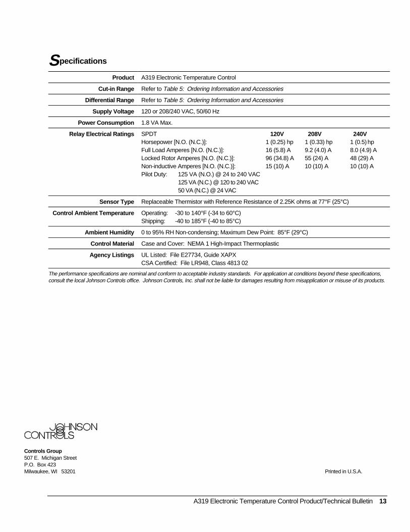
Product A319 Electronic Temperature Control
Cut-in Range Refer to Table 5: Ordering Information and Accessories
Differential Range Refer to Table 5: Ordering Information and Accessories
Supply Voltage 120 or 208/240 VAC, 50/60 Hz
Power Consumption 1.8 VA Max.
Relay Electrical Ratings SPDT 120V 208V 240VHorsepower [N.O. (N.C.)]: 1 (0.25) hp 1 (0.33) hp 1 (0.5) hpFull Load Amperes [N.O. (N.C.)]: 16 (5.8) A 9.2 (4.0) A 8.0 (4.9) ALocked Rotor Amperes [N.O. (N.C.)]: 96 (34.8) A 55 (24) A 48 (29) ANon-inductive Amperes [N.O. (N.C.)]: 15 (10) A 10 (10) A 10 (10) APilot Duty: 125 VA (N.O.) @ 24 to 240 VAC
125 VA (N.C.) @ 120 to 240 VAC50 VA (N.C.) @ 24 VAC
Sensor Type Replaceable Thermistor with Reference Resistance of 2.25K ohms at 77°F (25°C)
Control Ambient Temperature Operating: -30 to 140°F (-34 to 60°C)Shipping: -40 to 185°F (-40 to 85°C)
Ambient Humidity 0 to 95% RH Non-condensing; Maximum Dew Point: 85°F (29°C)
Control Material Case and Cover: NEMA 1 High-Impact Thermoplastic
Agency Listings UL Listed: File E27734, Guide XAPXCSA Certified: File LR948, Class 4813 02
The performance specifications are nominal and conform to acceptable industry standards. For application at conditions beyond these specifications,consult the local Johnson Controls office. Johnson Controls, Inc. shall not be liable for damages resulting from misapplication or misuse of its products.
Controls Group507 E. Michigan StreetP.O. Box 423Milwaukee, WI 53201 Printed in U.S.A.


![Flight Controls - SmartCockpit - Airline training guides ... · PDF fileAirbus A319-320-321 [Flight Controls] Page 100. Airbus A319-320-321 [Flight Controls] Page 101. Airbus A319-320-321](https://img.pdfslide.us/doc/110x75/5aa53a387f8b9a185d8d0880/flight-controls-smartcockpit-airline-training-guides-a319-320-321-flight.jpg)
![Fuel System - SmartCockpit · Airbus A319-320-321 [Fuel System] Page 1. Airbus A319-320-321 [Fuel System] Page 2. Airbus A319-320-321 [Fuel System] Page 3](https://img.pdfslide.us/doc/110x75/5e92c30e78777b5f2b4e604d/fuel-system-airbus-a319-320-321-fuel-system-page-1-airbus-a319-320-321-fuel.jpg)
![Electrical - SmartCockpit · Airbus A319-320-321 [Electrical] Page 1. Airbus A319-320-321 [Electrical] Page 2. Airbus A319-320-321 [Electrical] Page 3](https://img.pdfslide.us/doc/110x75/5b7559507f8b9ad8518d5abb/electrical-airbus-a319-320-321-electrical-page-1-airbus-a319-320-321-electrical.jpg)

![Equipment - SmartCockpit A319-320-321 [Equipment] Page 28-3229 3294 3761-3816 ... Airbus A319-320-321 [Equipment] Page 46. Airbus A319-320-321 [Equipment] Page 47. Title](https://img.pdfslide.us/doc/110x75/5aaae6367f8b9a6c188ed0d9/equipment-a319-320-321-equipment-page-28-3229-3294-3761-3816-airbus-a319-320-321.jpg)
![Fire Protection - SmartCockpit A319-320-321 [Fire Protection] Page 1. Airbus A319-320-321 [Fire Protection] ... [Fire Protection] Page 46. Airbus A319-320-321 [Fire Protection] Page](https://img.pdfslide.us/doc/110x75/5aaae6367f8b9a6c188ed0d4/fire-protection-a319-320-321-fire-protection-page-1-airbus-a319-320-321-fire.jpg)