Embed Size (px)
Citation preview


2
A312a: Understanding User Needs for Transportation Sensor Systems (TSS) Based on NTCIP 1209
Standard


4
Instructor
Ralph W. Boaz President Pillar Consulting, Inc. San Diego, CA, USA
5
Target Audience
Traffic engineering staff Traffic Management Center (TMC)/operations staff System developers Private and public sector users including manufacturers

6
Recommended Prerequisite(s)
I101: Using ITS Standards: An Overview
A101: Introduction to Acquiring Standards-based ITS Systems
A102: Introduction to User Needs Identification
A201: Details On Acquiring Standards-based ITS Systems
C101: Introduction to the Communications Protocols and Their Uses in ITS Applications

Curriculum Path (SEP) I101
Using ITS Standards: An
Overview
A101 Introduction to
Acquiring Standards -based
ITS Systems
A102 Introduction to
User Needs Identification
A201 Details on Acquiring Standards-based ITS
Systems
C101 Intro. to Comm.
Protocols and Their Use in ITS
Applications
A312a Understanding User Needs for Transportation Sensor Systems
(TSS) Based on NTCIP 1209 Standard
A312b Specifying Requirements for
Transportation Sensor Systems (TSS) Based on NTCIP
1209 Standard

8
Learning Objectives
1. Review the structure of the NTCIP 1209 v02 Standard
2. Identify TSS specific user needs
3. Use the Protocol Requirements List (PRL) to select user needs and link to requirements
4. Explain how the PRL table in the TSS Standard integrates into the specification

9
Learning Objective #1 – Review the Structure of the NTCIP 1209 v02 Standard
Purpose of the NTCIP 1209 v02 Standard
Structure of the NTCIP 1209 v02 Standard
How the standard fits into the systems life cycle

10
Purpose of the NTCIP 1209 v02 Standard
The purpose of the NTCIP 1209 v02 Standard is to
define the NTCIP communications requirements and
specifications, which provide interoperability
between a transportation sensor system and a
management station.
Learning Objective #1

11
Definition of a Sensor System
Learning Objective #1
Sensor, Traffic Sensor, Sensor System A physical device used for sensing traffic
Numerous types of sensor technologies in use today
Differing sensor technologies have advantages and disadvantages
Generic term used in the industry when referring to an entire sensing device

12
Typical Sensor Deployment Learning Objective #1
Management Station
On-Street Cabinet Containing Field Devices Including Various Sensor Elements
Traffic
Sensor Technology (not communications)
Proprietary MS-to-Sensor Communications (if exists)
Graphics: Ralph W. Boaz
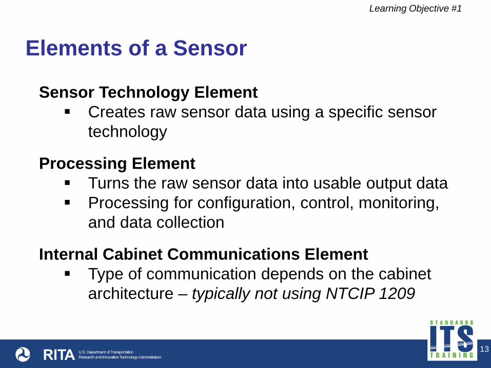
Elements of a Sensor
Learning Objective #1
Sensor Technology Element Creates raw sensor data using a specific sensor
technology
Processing Element Turns the raw sensor data into usable output data Processing for configuration, control, monitoring,
and data collection
Internal Cabinet Communications Element Type of communication depends on the cabinet
architecture – typically not using NTCIP 1209
13

Elements of a Sensor (cont.)
Learning Objective #1
Remote Communications Element Often proprietary communications are used Ideal use of NTCIP 1209 – if customer specifies it
14

15
Sensor Technologies In Use Today
Learning Objective #1
Infrared
Laser
Piezoelectric
Pneumatic
Light-Sensitive
Others
Loop
Video
Microwave Radar
Magnetometer
Acoustic
Ultrasonic

16
Example – Sensor Technology Element
Learning Objective #1
Video Image Sensor Inductive Loop
Photos: Ralph W. Boaz

17
Example – Processing Element Learning Objective #1
Transportation Cabinet
Video Image Processor
Loop Detector
Photos: Ralph W. Boaz

18
Example – Communication Elements
Learning Objective #1
Communication within (this) cabinet uses a connector on the processor to a wired cabinet backplane
Communication for remote access to the video image processor (typically Ethernet or serial) Covered by NTCIP 1209 Standard
if specified by customer
Not covered by NTCIP 1209 Standard
Photo: Ralph W. Boaz

19
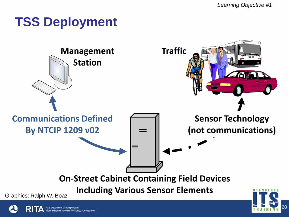
Definition of a TSS within NTCIP 1209
A Transportation Sensor System (TSS) is defined as any
system or device capable of sensing and communicating
near real-time traffic parameters using NTCIP.
Learning Objective #1
Proprietary MS-to-Sensor Communications (if exists)
20
TSS Deployment Learning Objective #1
On-Street Cabinet Containing Field Devices Including Various Sensor Elements
Management Station
Traffic
Communications Defined By NTCIP 1209 v02
Sensor Technology (not communications)
Graphics: Ralph W. Boaz

21
Clarification on Terminology
A Transportation Sensor System (TSS) is considered a field device from an NTCIP perspective
It may be a relatively simple device or a combination of devices working together
Don’t confuse a TSS with other systems that require center-to-center communications
Learning Objective #1

22
Benefits of the NTCIP 1209 v02 Standard
Learning Objective #1
Identifies operational user needs for traffic parameters within a system
Establishes a common understanding of the essential features for TSS equipment
Facilitates testing by providing clear and verifiable interface requirements and specifications

23
Benefits of the NTCIP 1209 v02 Standard (cont.)
Learning Objective #1
Promotes understanding of the standard by providing traceability between user needs, requirements, and detailed specifications
Provides tools (tables) for users to include in specifications that accurately define an NTCIP TSS interface
Facilitates compatibility, interoperability, and interchangeability of TSS equipment within a center-to-field system
24
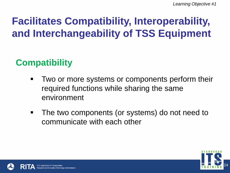
Facilitates Compatibility, Interoperability, and Interchangeability of TSS Equipment
Learning Objective #1
Two or more systems or components perform their required functions while sharing the same environment
The two components (or systems) do not need to communicate with each other
Compatibility

25
Facilitates Compatibility, Interoperability, and Interchangeability of TSS Equipment
Learning Objective #1
NTCIP
Compatibility
Graphics: Ralph W. Boaz

26
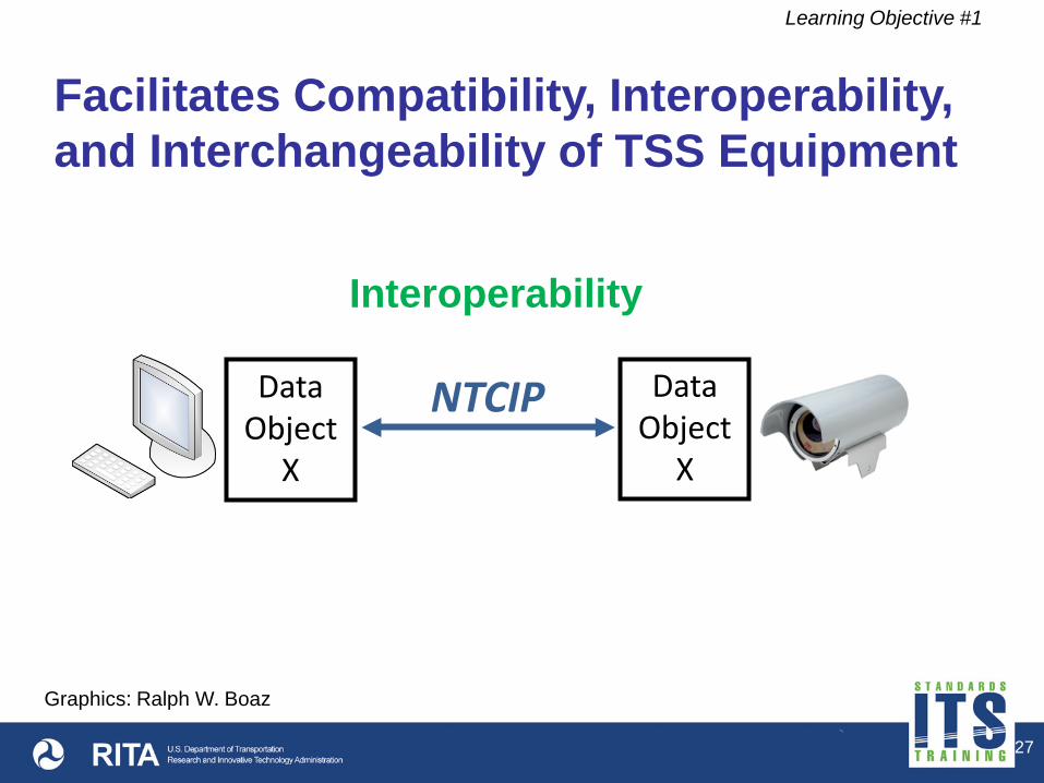
Facilitates Compatibility, Interoperability, and Interchangeability of TSS Equipment
Learning Objective #1
Ability of two or more devices to exchange information
Ability to use the information that has been exchanged
Interoperability
27
Facilitates Compatibility, Interoperability, and Interchangeability of TSS Equipment
Learning Objective #1
NTCIP
Interoperability
Data Object
X
Data Object
X
Graphics: Ralph W. Boaz

28
Facilitates Compatibility, Interoperability, and Interchangeability of TSS Equipment
Learning Objective #1
Same functional and physical characteristics so as to be equivalent in performance and durability (subjective)
Ability to exchange devices of the same type without alteration to the device or adjoining items (adjustments permitted, subjective)
Interchangeability

29
Facilitates Compatibility, Interoperability, and Interchangeability of TSS Equipment
Learning Objective #1
Interchangeability NTCIP
Graphics: Ralph W. Boaz

30
Structure of the NTCIP 1209 v02 Standard
Learning Objective #1
Section 1 General
Section 2 TSS Concept of Operations (ConOps)
Section 3 TSS Functional Requirements (includes Protocol Requirements List)
Section 4 TSS Dialogs
Section 5 Management Information Base (MIB)

31
Structure of the NTCIP 1209 v02 Standard (cont.)
Learning Objective #1
Annex A Requirements Traceability Matrix (RTM)
Annex B Object Tree
Annex C Test Procedures (placeholder for the future)
Annex D Document Revisions

32
History of NTCIP 1209
Learning Objective #1
NTCIP 1209 v01 Oriented towards inductive loop technology Did not contain SE information
NTCIP 1209 v02 Added SE information Organized around features Options for selecting requirements for specific
technologies (inductive loop and machine vision) Structure conducive for including additional specific
technology requirements in the future

33
How NTCIP 1209 v02 Fits into the Systems Life Cycle
Learning Objective #1
A systems engineering process (SEP) was used in the development of NTCIP 1209 v02
SE information is included in the standard’s content
Helps insure that the standard is complete and correct
Provides users with the thought process of the standard developers and use of the design items

34
How NTCIP 1209 v02 Fits into the Systems Life Cycle (cont.)
Learning Objective #1
Use of NTCIP standards usually starts in the design phases of system development
Considered a part of the subsystem interfaces
Helps users identify needs and requirements for their own specifications and other documents that reference the standards

35
Learning Objective #1
How NTCIP 1209 v02 Fits into the Systems Life Cycle
Life Cycle Processes

Life Cycle Processes
36
Learning Objective #1
How NTCIP 1209 v02 Fits into the Systems Life Cycle
NTCIP 1209 v02
National Transportation Communications for ITS Protocol Data Element Definitions for Transportation Sensor Systems Joint Standard of AASHTO, ITE and NEMA
Graphics: Ralph W. Boaz


38
Learning Objective #1
A _______ is defined as any system or device capable of sensing and communicating _______ real-time traffic parameters using _______.
Answer Choices
a) detector; fast; Ethernet b) controller; conformant; NTCIP c) NTCIP; conformant; Ethernet d) TSS; near; NTCIP

39
Learning Objective #1
Review of Answers a) detector; fast; Ethernet Incorrect. Ethernet is not the only communications medium that can be used for a TSS. b) controller; conformant; NTCIP Incorrect. A controller doesn’t do sensing but it may use the sensor information or provide it to a central computer. c) NTCIP; conformant; Ethernet Incorrect. NTCIP is a protocol not a system or device. d) TSS; near; NTCIP Correct. This completes the definition of a TSS.

40
Learning Objective #1
a) Creates raw sensor data using a specific sensor technology
b) Turns the raw sensor data into usable output data c) Transfers output data to other devices or systems
internal to the field cabinet d) Transfers output data to other devices or systems
external to the field cabinet
What is the role of the processing element of a TSS?
Answer Choices

41
Learning Objective #1
Review of Answers a) Creates raw sensor data using a specific sensor
technology Incorrect. This is a role of the sensor technology element. b) Turns the raw sensor data into usable output data Correct. This is the role of the processing element. c) Transfers output data to other devices or systems
internal to the field cabinet Incorrect. This is the role of the internal cabinet communications element. d) Transfers output data to other devices or systems
external to the field cabinet Incorrect. This is the role of the remote communications element.

42
Summary of Learning Objective #1
Purpose of the NTCIP 1209 v02 Standard
Components and structure of the NTCIP 1209 v02 Standard
How the standard fits into the systems life cycle
Review the Structure of the NTCIP 1209 v02 Standard

43
Learning Objective #2 – Identify TSS User Needs
Architecture of a TSS
Define TSS terms and concepts
User needs (expressed as “Features”)

44
Traditional Detection Architecture
Learning Objective #2
Loops in Roadway
Proprietary Comm. (if exists)
Electrical
Traffic Controllers Detector(s) Discrete I/O or Serial Comm.
Management Station
Graphics: Ralph W. Boaz

45
Learning Objective #2
App1
App2
App3
App4
Proprietary Comm.
Traditional Detection Architecture An application program for each type and brand of sensor device
Graphics: Ralph W. Boaz
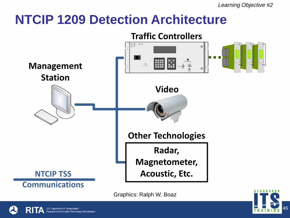
46
NTCIP 1209 Detection Architecture Learning Objective #2
NTCIP TSS Communications
Management Station
Traffic Controllers
Radar, Magnetometer,
Acoustic, Etc.
Other Technologies
Video
Graphics: Ralph W. Boaz

47
Learning Objective #2
NTCIP App
Single application program for each type and brand of sensor device
NTCIP 1209 Detection Architecture
Graphics: Ralph W. Boaz

48
Definition of Terms Learning Objective #2
Zone
An area in which traffic parameters can be measured and/or traffic data can be generated

49
Example Zone Configurations
Learning Objective #2
Z1
Z2
Z3 Z4
Zones at an Intersection
Zones on a Highway
Z1
Z2
Z3
Z4Graphics: Ralph W. Boaz

50
Definition of Terms Learning Objective #2
Sample
A collection of sensor data for a zone over a known time period
Sample Period
Duration of time in seconds when data for the zone is being collected
Class
Subdivision of collected historical sample data Typically one or more classifications of
vehicles as defined by FHWA

51
Definition of Terms
Learning Objective #2
Output
The condition of an on/off status of a zone generated by a change of state
Delay
A feature that allows the zone output to be deferred for a user set time period
Extension
A feature that allows the zone output from a TSS detector to be lengthened for a user set time period

52
Output After Delay
Learning Objective #2
Z1
Z2
Z3 Z4
Output for Zone 1 is ON only if a vehicle is present for >= 4 seconds Allows right turners to roll over Zone 1 without
triggering signal Provides right turners a signal call if they are sitting
Graphics: Ralph W. Boaz

53
Output With Extension
Learning Objective #2
Z1
Z2
Z3 Z4
Output for Zone 2 is ON for an additional 3 seconds after a vehicle is no longer present Increases opportunities for straight through traffic
flow without changing the signal timing plan
Graphics: Ralph W. Boaz

54
Definition of Terms Learning Objective #2
Virtual Zone
A logical combination of one or more zones to create a new zone with its own conditioning and Arming Enables
Conditioning
When a zone uses logical ANDing, ORing, or SEQing of the outputs of other zones and/or external Arming Inputs or Arming Pins to activate its own Delay, Extend, or Output

55
Multi Lane Detect Z10 = OR (Z1,Z2)
Queue Detect Z11 = AND (Z3,Z4)
Wrong Way Detect Z12 = SEQ (Z6,Z7)
Learning Objective #2
Z1
Z2
Z3 Z4
Z6 Z5 Z7
WRONG WAY
Zones, Virtual Zones, and Logic
Graphics: Ralph W. Boaz

56
Definition of Terms
Learning Objective #2
Arming Enable
Used to set the selected state of an Arming Input Bit or Arming Pin of the TSS that is to be used to modify zone operations
Arming Input Bit
An external event that is reported to the TSS using this protocol and used to modify its operation
Arming Pin
A physical input to the TSS that can be monitored and used to modify its operation
57
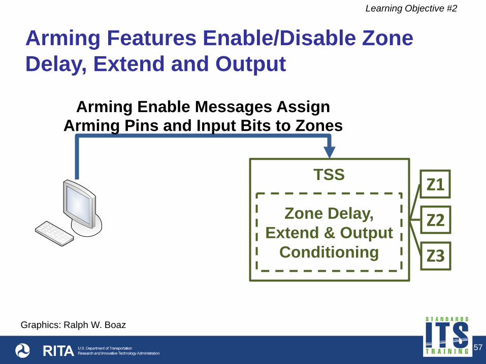
Learning Objective #2
Z1
Z2
Z3
Zone Delay, Extend & Output
Conditioning
TSS
Arming Features Enable/Disable Zone Delay, Extend and Output
Arming Enable Messages Assign Arming Pins and Input Bits to Zones
Graphics: Ralph W. Boaz

58
Learning Objective #2
Z1
Z2
Z3
Zone Delay, Extend & Output
Conditioning
TSS
Arming Features Enable/Disable Zone Delay, Extend and Output (cont.)
Arming Inputs Bits Message
Arming Input Pins
TSS Outputs Graphics: Ralph W. Boaz

59
Operations of TSS Devices
Learning Objective #2
Configure
Control
Monitor
Collect Data

60
Features for Configuring TSS Devices
Learning Objective #2
2.5.1.1 Determine the TSS Identity (M) Used to determine basic information about the TSS Includes sensor technology, manufacturer, model,
firmware version, hardware version, TSS protocol version, and TSS standards revision
2.5.1.2 Determine TSS Capabilities (M) Used to determine, configure, and manage the TSS Includes maximum number of zones, maximum number
of historical data entries per zone, maximum number of sample periods per zone, etc.

61
Features for Configuring TSS Devices (cont.)
Learning Objective #2
2.5.1.3 Determine the Sequence of Sample Periods (Sample:M)
Used to determine the sequence of sample periods so that aggregate data can be used to identify changes in traffic
2.5.1.4 Determine the Age of Sample Data (Sample:M) Used to determine the age of sample period data so that
the relevance of the data to current traffic conditions can be determined
62
Features for Configuring TSS Devices (cont.)
Learning Objective #2
2.5.1.5 Configure Zones (M) Used to configure the sampling period, zone label,
number of classes, combinations of zones, sequences, and other zone parameters
Includes special operational parameters for specific TSS technologies
2.5.1.6 Configure Arming Enables (Timing:O) Used to configure the Arming Enables that are used
to modify the zone output, delay, and extension timing
63
Features for Configuring TSS Devices (cont.)
Learning Objective #2
2.5.1.7 Configure Outputs (M) Used to configure the outputs to report the state of
zones Includes assigning an output to a zone, conditioning
of outputs to include delay and extension, assigning fail-safe/fail-secure mode of operation, etc.
2.5.1.8 Manage Pending Configuration File Name (O) Used to transfer, validate, and execute a configuration
file
64
Subfeatures for 2.5.1.2 Determining the TSS Capabilities
Learning Objective #2
2.5.1.2.1 Determine TSS Support for Sampling (M) Used to determine if the TSS supports sampling Support for sampling indicates the TSS is capable of
collecting sample data and storing it for retrieval 2.5.1.2.2 Determine TSS Support for Timing (M) Used to determine if the TSS supports timing functions Support for timing indicates the TSS is capable of
modifying the operation of zones and outputs through user-specified timing parameters

65
Subfeatures for 2.5.1.2 Determining the TSS Capabilities (cont.)
Learning Objective #2
2.5.1.2.3 Determine TSS Support for Speed (M) Used to determine if TSS supports speed functions Support for speed indicates that the TSS is capable of
providing vehicle speed and storing it for retrieval through the sampling functions
2.5.1.2.4 Determine TSS Support for Real-Time Clock (M) Used to determine if TSS supports a Real-Time Clock
(RTC) Support for RTC indicates that the TSS is capable of
providing actual local time


67
Learning Objective #2
a) Sampling b) Timing c) Location d) Speed
Which one of the following choices is NOT considered a capability for the TSS?
Answer Choices

68
Learning Objective #2
Review of Answers a) Sampling Incorrect. The ability to collect data and store it for retrieval is a capability of a TSS. b) Timing Incorrect. The ability for users to modify the use of zones through timing parameters is a capability of a TSS. c) Location Correct. Providing location information is not considered a capability of a TSS at this time. d) Speed Incorrect. The ability to determine vehicle speed and store it for retrieval is a capability of a TSS.

69
Features for Controlling TSS Devices
Learning Objective #2
2.5.2.1 Reset the TSS (M) Used to set the TSS to a known condition such as
restart, reinitialize, or retune Used to cause the TSS to execute, abort, or validate
a pending configuration file 2.5.2.2 Initiate Sensor Diagnostics (M) Used to initiate sensor diagnostic routines
2.5.2.3 Synchronize the TSS (Sample:M) Used to set the baseline reference for the sampling
period

70
Features for Controlling TSS Devices (cont.)
Learning Objective #2
2.5.2.4 Update Arming Input Bits of the TSS (Timing:O) Used to update the status of the Arming Input Bits of
the TSS 2.5.2.5 Manage the Camera (Video:M) Used to enable or disable detection for a particular
camera location Used to verify a camera is working and is pointing at
the correct detection area Used to determine number of cameras and video
formats Can command a camera to build an image file and
transfer it to the management station

71
Features for Controlling TSS Devices (cont.)
Learning Objective #2
2.5.2.6 Manage the Real-Time Clock (RTC:M) Used to configure an RTC for the purpose of providing
a timestamp for sample data Clock should be able to support Daylight Saving Time
(DST) adjustments


73
Learning Objective #2
a) Synchronize the TSS b) Initiate Sensor Diagnostics c) Reset the TSS d) Update Arming Input Bits of the TSS
Which of the following Control features allows the TSS to be set to a known condition?
Answer Choices
74
Learning Objective #2
Review of Answers a) Synchronize the TSS Incorrect. This sets the baseline reference for the sampling period. b) Initiate Sensor Diagnostics Incorrect. This allows operators to initiate sensor diagnostic routines. c) Reset the TSS Correct. This allows the TSS to be set to a known condition. d) Update Arming Input Bits of the TSS Incorrect. This updates the status of the Arming Input Bits of the TSS.

75
Features for Monitoring TSS Devices
Learning Objective #2
2.5.3.1 Monitor System Status (M) Used to monitor the system status of the TSS such
that the management station identifies that the system is operating normally
2.5.3.2 Monitor TSS Sensor Status (M) Used to monitor the status of each sensor within the
TSS Only the sensor status of inductive loop and machine
vision sensors are defined in NTCIP 1209 v02

76
Features for Monitoring TSS Devices
Learning Objective #2
2.5.3.3 Monitor Output States (M) Used to retrieve the states of multiple outputs of
the TSS 2.5.3.4 Monitor Zone Status (M) Used to monitor the status of each zone


78
Learning Objective #2
a) Monitor System Status b) Monitor TSS Sensor Status c) Monitor Output States d) Monitor Zone Status
Which of the following monitoring features lets a system or user know that there is a loss of contrast on a video detection camera?
Answer Choices

79
Learning Objective #2
Review of answers a) Monitor System Status Incorrect. This may be used to detect a general problem on the TSS device. b) Monitor TSS Sensor Status Correct. This is used to detect a problem with the sensor portion of the TSS device. c) Monitor Output States Incorrect. This is used to retrieve the states of multiple outputs of the TSS device. d) Monitor Zone Status Incorrect. This is used to retrieve the status of each zone of the TSS device.
80
Features for Collecting Data from TSS Devices
Learning Objective #2
2.5.4.1 Retrieve In-Progress Sample Data (Sample: M, Speed: M) Used to obtain the data from the in-progress (started
but not yet completed) sample period Includes length of elapsed time in the reported
sample period, volume, percent of occupancy, speed, and zone status during the sampling period

81
Features for Collecting Data from TSS Devices (cont.)
Learning Objective #2
2.5.4.2 Retrieve Current Sample Data (Sample: M, Speed: M) Used to obtain the data from the current sample
period Includes when the sample period ended, volume,
percent of occupancy, speed, and zone status during the sampling period

82
Features for Collecting Data from TSS Devices (cont.)
Learning Objective #2
2.5.4.3 Retrieve Historical Sample Data (Sample: M, Speed: M) Used to retrieve historical sample data from previous
sample periods Historical, in this context, refers to past sample
periods for the sensor – not an archive of data


84
Learning Objective #2
a) Retrieve In-Progress Sample Data b) Retrieve Current Sample Data c) Retrieve Historical Sample Data d) None of the above
Which of the following Collecting features identifies the user need to retrieve yearly average volume data from a TSS?
Answer Choices

85
Learning Objective #2
Review of Answers a) Retrieve In-Progress Sample Data Incorrect. This is used to obtain data for the in-progress (started but not yet completed) sample period. b) Retrieve Current Sample Data Incorrect. This is used to obtain the data from the current sample period. c) Retrieve Historical Sample Data Incorrect. This is used to retrieve historical sample data from previous sample periods. d) None of the above Correct. The TSS device is not required to store data for long periods of time.

86
Summary of Learning Objective #2
Identify TSS User Needs
Architecture of a TSS
Define TSS Terms and Concepts
User Needs (expressed as “Features”)

87
Learning Objective #3 – Use the Protocol Requirements List (PRL) to Select User Needs and Link to Requirements
Understand the parts of the PRL
Use the PRL as a tool for project-specific implementations
Reduce the risk of failure

88
Learning Objective #3
Protocol Requirements List
A table provided in the NTCIP 1209 v02 Standard that is used as a tool by specification writers
Shows the relationship of user needs (features) to functional requirements and rules for conformance to the standard
Specification writers “tailor” the PRL according to their particular system needs
Not all user needs and requirements are necessary or possible in a given deployment
When a deployment satisfies the requirements in the specification, it is said to be compliant

89
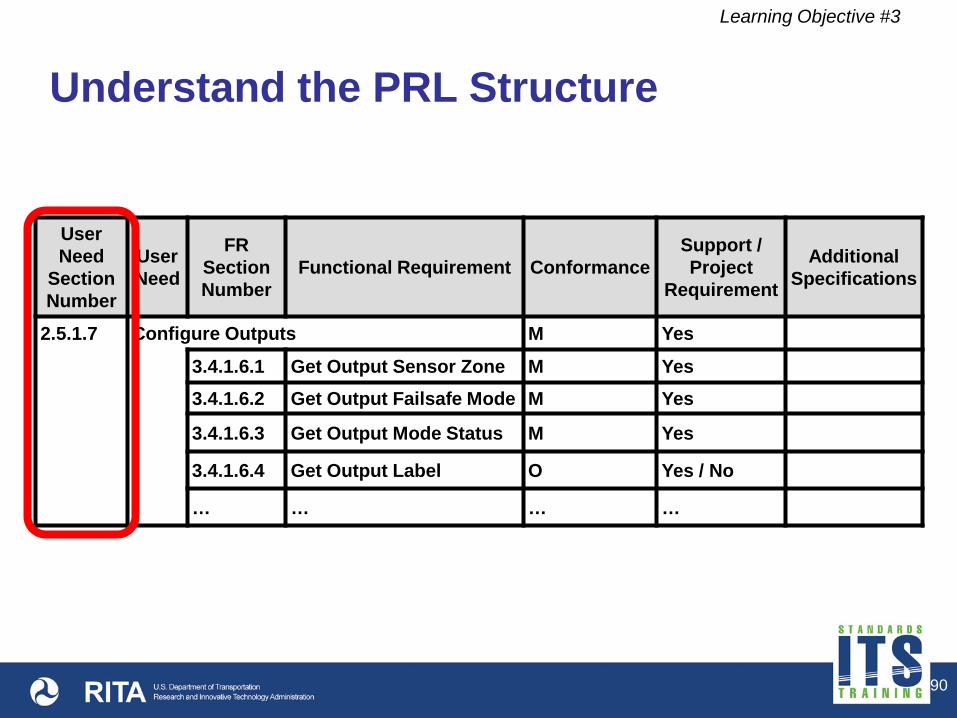
Understand the PRL Structure
Learning Objective #3
User Need
Section Number
User Need
FR Section Number
Functional Requirement Conformance Support / Project
Requirement
Additional Specifications
2.5.1.7 Configure Outputs M Yes
3.4.1.6.1 Get Output Sensor Zone M Yes 3.4.1.6.2 Get Output Failsafe Mode M Yes
3.4.1.6.3 Get Output Mode Status M Yes
3.4.1.6.4 Get Output Label O Yes / No
… … … …
90
Understand the PRL Structure
Learning Objective #3
User Need
Section Number
User Need
FR Section Number
Functional Requirement Conformance Support / Project
Requirement
Additional Specifications
2.5.1.7 Configure Outputs M Yes
3.4.1.6.1 Get Output Sensor Zone M Yes 3.4.1.6.2 Get Output Failsafe Mode M Yes
3.4.1.6.3 Get Output Mode Status M Yes
3.4.1.6.4 Get Output Label O Yes / No
… … … …

91
Understand the PRL Structure
Learning Objective #3
User Need
Section Number
User Need
FR Section Number
Functional Requirement Conformance Support / Project
Requirement
Additional Specifications
2.5.1.7 Configure Outputs M Yes
3.4.1.6.1 Get Output Sensor Zone M Yes 3.4.1.6.2 Get Output Failsafe Mode M Yes
3.4.1.6.3 Get Output Mode Status M Yes
3.4.1.6.4 Get Output Label O Yes / No
… … … …

92
Understand the PRL Structure
Learning Objective #3
User Need
Section Number
User Need
FR Section Number
Functional Requirement Conformance Support / Project
Requirement
Additional Specifications
2.5.1.7 Configure Outputs M Yes
3.4.1.6.1 Get Output Sensor Zone M Yes 3.4.1.6.2 Get Output Failsafe Mode M Yes
3.4.1.6.3 Get Output Mode Status M Yes
3.4.1.6.4 Get Output Label O Yes / No
… … … …

93
Understand the PRL Structure
Learning Objective #3
User Need
Section Number
User Need
FR Section Number
Functional Requirement Conformance Support / Project
Requirement
Additional Specifications
2.5.1.7 Configure Outputs M Yes
3.4.1.6.1 Get Output Sensor Zone M Yes 3.4.1.6.2 Get Output Failsafe Mode M Yes
3.4.1.6.3 Get Output Mode Status M Yes
3.4.1.6.4 Get Output Label O Yes / No
… … … …

94
Understand the PRL Structure
Learning Objective #3
User Need
Section Number
User Need
FR Section Number
Functional Requirement Conformance Support / Project
Requirement
Additional Specifications
2.5.1.7 Configure Outputs M Yes
3.4.1.6.1 Get Output Sensor Zone M Yes 3.4.1.6.2 Get Output Failsafe Mode M Yes
3.4.1.6.3 Get Output Mode Status M Yes
3.4.1.6.4 Get Output Label O Yes / No
… … … …

95
Understand the PRL Structure
Learning Objective #3
User Need
Section Number
User Need
FR Section Number
Functional Requirement Conformance Support / Project
Requirement
Additional Specifications
2.5.1.7 Configure Outputs M Yes
3.4.1.6.1 Get Output Sensor Zone M Yes 3.4.1.6.2 Get Output Failsafe Mode M Yes
3.4.1.6.3 Get Output Mode Status M Yes
3.4.1.6.4 Get Output Label O Yes / No
… … … …

96
Understand the PRL Structure
Learning Objective #3
User Need
Section Number
User Need
FR Section Number
Functional Requirement Conformance Support / Project
Requirement
Additional Specifications
2.5.1.7 Configure Outputs M Yes
3.4.1.6.1 Get Output Sensor Zone M Yes 3.4.1.6.2 Get Output Failsafe Mode M Yes
3.4.1.6.3 Get Output Mode Status M Yes
3.4.1.6.4 Get Output Label O Yes / No
… … … …

97
Use Conformance Status and Predicates for Specific Implementations
Learning Objective #3
Symbol Conformance Status M Mandatory O Optional
O.#
Part of an “Option Group” where “#” indicates the group number (e.g., “O.2” means Option Group 2). If a requirement associated with a particular Option Group is to be supported, then all requirements in the standard that are associated with that Option Group must also be supported.
N/A Not applicable (i.e., logically impossible in the scope of the standard)
Status Symbols
98
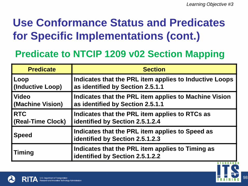
Use Conformance Status and Predicates for Specific Implementations (cont.)
Learning Objective #3
Predicate Section Loop (Inductive Loop)
Indicates that the PRL item applies to Inductive Loops as identified by Section 2.5.1.1
Video (Machine Vision)
Indicates that the PRL item applies to Machine Vision as identified by Section 2.5.1.1
RTC (Real-Time Clock)
Indicates that the PRL item applies to RTCs as identified by Section 2.5.1.2.4
Speed Indicates that the PRL item applies to Speed as identified by Section 2.5.1.2.3
Timing Indicates that the PRL item applies to Timing as identified by Section 2.5.1.2.2
Predicate to NTCIP 1209 v02 Section Mapping

99
Use Conformance Status and Predicates for Specific Implementations (cont.)
Learning Objective #3
Predicates Section
Sample Indicates that the PRL item applies to Sampling as identified by Section 2.5.1.2.1
Version1 Indicates that the PRL item applies to objects required to maintain MVI with NTCIP 1209:2005 v01 as identified by Section 2.5.5.1
Predicate to NTCIP 1209 v02 Section Mapping

100
Use Conformance Status and Predicates for Specific Implementations (cont.)
Learning Objective #3
User Need
Section Number
User Need
FR Section Number
Functional Requirement Conformance Support / Project
Requirement
Additional Specifications
2.5.2.5 Manage the Camera Video:M Yes / N/A
3.4.1.7.1 Set Disable Detection Video: O Yes / No / N/A
3.4.1.7.2 Get Disable Detection Video: O Yes / No / N/A
3.4.1.7.3 Set the Build Image Parameter Video: O.2 Yes / No /
N/A
3.4.1.7.4 Set Cancel Build In-Progress Video: O.2 Yes / No /
N/A

101
Use Conformance Status and Predicates for Specific Implementations (cont.)
Learning Objective #3
User Need
Section Number
User Need
FR Section Number
Functional Requirement Conformance Support / Project
Requirement
Additional Specifications
2.5.2.5 Manage the Camera Video:M Yes / N/A Video Predicate is Specified
3.4.1.7.1 Set Disable Detection Video: O Yes / No / N/A
3.4.1.7.2 Get Disable Detection Video: O Yes / No / N/A
3.4.1.7.3 Set the Build Image Parameter Video: O.2 Yes / No /
N/A
3.4.1.7.4 Set Cancel Build In-Progress Video: O.2 Yes / No /
N/A

102
Reduce the Risk of Failure
Learning Objective #3
PRL allows specification writers to only include the requirements applicable to their system
The PRL can be used as a check list to explicitly point out whether the product meets the user needs (features) and requirements of the system and whether off-the-shelf interoperability is achievable
Future purchases from other vendors can be compared
Using only requirements included in the standard reduces risk


104
Learning Objective #3
a) Tailor an NTCIP specification for a particular TSS technology
b) Learn the science used in sensor technologies c) Specify Ethernet communications d) Force TSS providers to support all requirements
in the standard
The PRL is a good tool to _____________.
Answer Choices

105
Learning Objective #3
Review of Answers
a) Tailor an NTCIP specification for a particular TSS technology Correct. Different technologies can be included or excluded
using predicates and user selections. b) Learn the science used in sensor technologies Incorrect. NTCIP 1209 addresses the configuration of a TSS and
communications interface only. c) Specify Ethernet communications Incorrect. The PRL is used for specifying interface requirements for a
field device, not for the media that carries it. d) Force TSS providers to support all requirements in the standard Incorrect. It is not reasonable for a TSS to adhere to all requirements
in the standard as some may not be compatible.

106
Summary of Learning Objective #3
Use the Protocol Requirements List (PRL) to Select User Needs and Link to Requirements
Understand the parts of the PRL
Use the PRL as a tool for project-specific implementations
Reduce the risk of failure

107
Learning Objective #4 – Explain How the PRL Table in the Standard Integrates into a Specification
Device Specifications and Agency Procurements
Integrate the PRL into the Specification

108
Device Specifications and Agency Procurements
Learning Objective #4
Agency specifications written based on how the agency purchases equipment
TSS devices often bought by contractors in response to construction bids
Agencies create standing specifications for protection
An agency may have a prequalified vendors list or have a single vendor selected through a bid process

109
Types of Requirements in an Agency Device Specification
Learning Objective #4
Hardware
Functional
Performance
Environmental
Interface
Maintenance
Procurement
Warranty
Others

Learning Objective #4
Draw Information from the NTCIP 1209 v02 Standard
Example Agency Sensor Specification General ConOps Requirements
Hardware Interface Functional Performance Environmental …
110
General ConOps Functional Reqs Design Details Annexes
NTCIP 1209 v02

111
Integrate the PRL into the Specification
Learning Objective #4
Think about your system architecture when writing the TSS specification
Expand the interface requirements of the specification to include NTCIP 1209 v02
Use a completed PRL table indicating the interface requirements for your TSS devices
Include the interface requirements for the protocols to be used in your system

112
Integrate the PRL into the Specification (cont.)
Learning Objective #4
Require the product be conformant to NTCIP 1209 v02
Make sure all of the requirements are consistent within the document (not just the interface requirements)


114
Learning Objective #4
a) Including the protocols used to communicate with the sensor
b) Excluding NTCIP requirements because your favorite vendor does not support them
c) Consistency between hardware and interface requirements
d) Conformance to the NTCIP 1209 v02 Standard
Which item below is NOT good practice when writing a specification for a sensor?
Answer Choices

115
Learning Objective #4
Review of answers a) Including the protocols used to communicate with the sensor Incorrect. The protocols (e.g. serial, Ethernet) used in the system should be identified in the specification. b) Excluding NTCIP requirements because your favorite vendor
does not support them Correct. Requirements should be based on present or future user needs, not on a favorite vendor. c) Consistency between hardware and interface requirements Incorrect. Inconsistent requirements in a specification may result in non-interoperable and non-interchangeable devices. d) Conformance to the NTCIP 1209 v02 Standard Incorrect. Conformance to the standard while tailoring the PRL for a specification is essential.

116
Summary of Learning Objective #4
Explain How the PRL Table in the Standard Integrates into a Specification
Device Specifications and Agency Procurements
Integrate the PRL into the Specification

117
What We Have Learned
1. Review the structure of the ____________________ Standard
2. Identify TSS specific ______________
3. Use the _____________________________________ to select user needs and link to requirements
4. Explain how the PRL table in the standard integrates into a ________________
NTCIP 1209 v02
user needs Protocol Requirements List (PRL)
specification

118
Resources
IEEE 830-1998 Recommended Practice for Software Requirements Specifications http://standards.ieee.org/findstds/standard/830-1998.html
ITS Professional Capacity Building Training http://www.pcb.its.dot.gov/standardstraining/
National Transportation Communications for ITS Protocol 1209 Object Definitions for Transportation Sensor Systems (TSS) Version 02 http://www.ntcip.org/library/documents/

119
Resources (cont.)
Systems Engineering Guidebook for Intelligent Transportation Systems Version 3.0 http://www.fhwa.dot.gov/cadiv/segb/
USDOT – FHWA Traffic Detector Handbook: Third Edition—Volume I. October 2006 http://www.fhwa.dot.gov/publications/research/operations/its/06108/


121
Next Course Module A312b: Specifying Requirements for Transportation Sensor Systems (TSS) Based on NTCIP 1209 Standard Describe requirements included in the NTCIP 1209 v02
Standard Use the Protocol Requirements List (PRL) to specify an
NTCIP TSS interface Achieve Interoperability and Interchangeability using the
Requirements Traceability Matrix (RTM) Incorporate requirements not covered by the standard Understand the NTCIP TSS SNMP interface and dialogs


![Indiana’s 2013‐2035 Future Transportation Needs Report ... · April 16, 2013 [INDIANA’S FUTURE TRANSPORTATION NEEDS REPORT ] 6 Introduction | Indiana Department of Transportation](https://img.pdfslide.us/doc/110x75/5fd8f1a1b91f773f5733bcb9/indianaas-2013a2035-future-transportation-needs-report-april-16-2013-indianaas.jpg)