Embed Size (px)
Citation preview

A300 SERIES, A3CV & CTM MAGNETRON SPUTTERING SOURCES
INSTALLATION &
OPERATION MANUAL
December 2004
NOTE:
Information and data in this manual are subject to periodic amendments, revisions and additions. Please consult factory for the most current information and revision.
AJA INTERNATIONAL PO Box 246, 809 Country Way
North Scituate, MA 02060
TEL: 781-545-7365 FAX: 781-545-4105 e-mail: [email protected]
WEB: www.ajaint.com
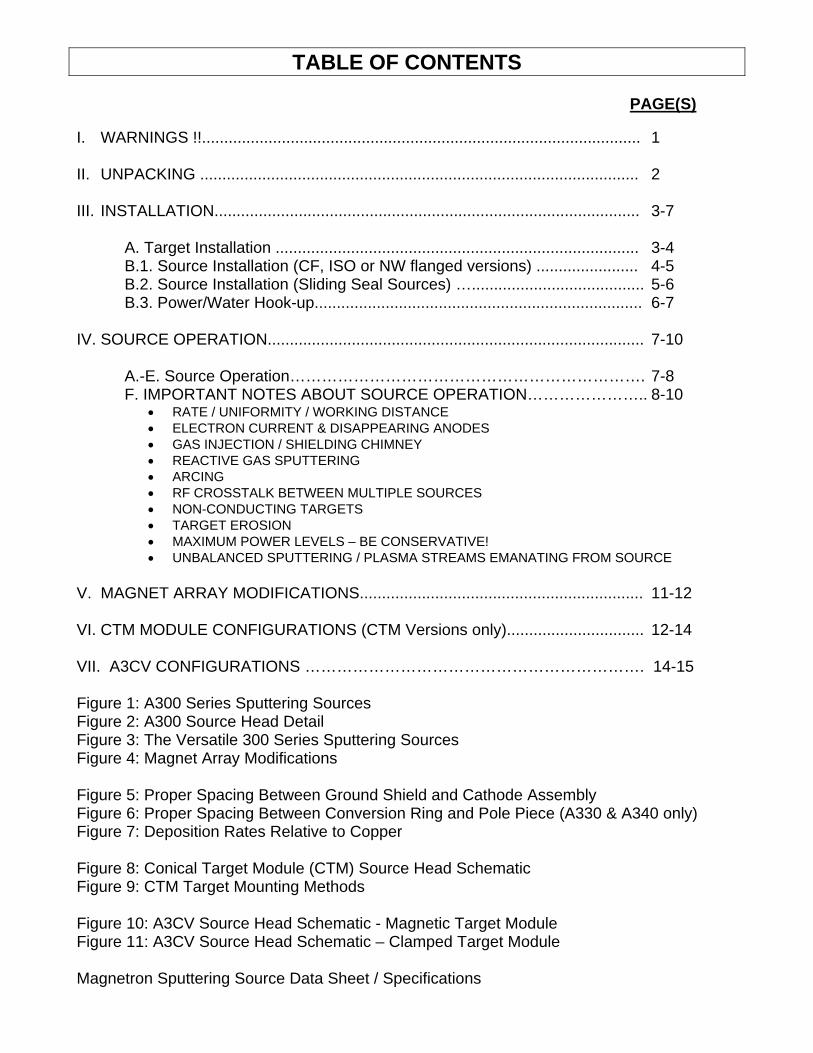
TABLE OF CONTENTS
PAGE(S) I. WARNINGS !!................................................................................................... 1 II. UNPACKING ................................................................................................... 2 III. INSTALLATION................................................................................................ 3-7 A. Target Installation .................................................................................. 3-4 B.1. Source Installation (CF, ISO or NW flanged versions) ....................... 4-5 B.2. Source Installation (Sliding Seal Sources) …....................................... 5-6 B.3. Power/Water Hook-up.......................................................................... 6-7 IV. SOURCE OPERATION..................................................................................... 7-10 A.-E. Source Operation…………………………………………………………. 7-8 F. IMPORTANT NOTES ABOUT SOURCE OPERATION………………….. 8-10
• RATE / UNIFORMITY / WORKING DISTANCE • ELECTRON CURRENT & DISAPPEARING ANODES • GAS INJECTION / SHIELDING CHIMNEY • REACTIVE GAS SPUTTERING • ARCING • RF CROSSTALK BETWEEN MULTIPLE SOURCES • NON-CONDUCTING TARGETS • TARGET EROSION • MAXIMUM POWER LEVELS – BE CONSERVATIVE! • UNBALANCED SPUTTERING / PLASMA STREAMS EMANATING FROM SOURCE
V. MAGNET ARRAY MODIFICATIONS................................................................ 11-12 VI. CTM MODULE CONFIGURATIONS (CTM Versions only)............................... 12-14 VII. A3CV CONFIGURATIONS ………………………………………………………. 14-15 Figure 1: A300 Series Sputtering Sources Figure 2: A300 Source Head Detail Figure 3: The Versatile 300 Series Sputtering Sources Figure 4: Magnet Array Modifications Figure 5: Proper Spacing Between Ground Shield and Cathode Assembly Figure 6: Proper Spacing Between Conversion Ring and Pole Piece (A330 & A340 only) Figure 7: Deposition Rates Relative to Copper Figure 8: Conical Target Module (CTM) Source Head Schematic Figure 9: CTM Target Mounting Methods Figure 10: A3CV Source Head Schematic - Magnetic Target Module Figure 11: A3CV Source Head Schematic – Clamped Target Module Magnetron Sputtering Source Data Sheet / Specifications

-1- I. WARNINGS !! FAILURE TO PROPERLY INSTALL OR OPERATE THIS PRODUCT CAN RESULT IN PRODUCT DAMAGE, RF INTERFERENCE, ELECTROCUTION, BURNS, EYE INJURY OR DEATH. PLEASE EXERCISE EXTREME CAUTION IN OPERATION OR MODIFICATION OF THIS EQUIPMENT AND BE CERTAIN ALL PERSONNEL COMING INTO CONTACT WITH THE EQUIPMENT ARE AWARE OF THE FOLLOWING HAZARDS: HIGH VOLTAGE: THIS PRODUCT REQUIRES CONNECTION TO A HIGH VOLTAGE RF OR DC SOURCE. BEFORE ATTEMPTING OPERATION OR CONNECTION TO A COAXIAL POWER CABLE, ALWAYS CHECK TO ASSURE DISCONTINUITY BETWEEN CENTER PIN OF THE COAXIAL CONNECTOR AND BOTH CHAMBER AND BODY OF COAXIAL CONNECTOR. IT IS ABSOLUTELY ESSENTIAL THAT THE VACUUM CHAMBER AND BODY OF THE COAXIAL CONNECTOR BE PROPERLY GROUNDED AND AT THE SAME POTENTIAL. RF AND DC POWER: NEVER APPLY POWER TO THE SOURCE UNLESS THE HEAD OF THE SOURCE IS UNDER VACUUM BELOW 1 TORR AND NO LIVE CONNECTIONS ARE EXPOSED. THIS ENSURES THAT NO OPERATING PERSONNEL CAN BE IN CONTACT WITH ANY LIVE AREA OF THE SOURCE. STRONG MAGNETIC FIELDS – PACEMAKER & ELECTRONICS RISK!!!!: MAGNETRON SPUTTERING SOURCES ARE FITTED WITH STRONG RARE EARTH MAGNETS WHICH MAY ADVERSELY AFFECT PACEMAKER OPERATION AND WHICH MAY ERASE OR CORRUPT THE MEMORY IN ELECTRONIC DEVICES RENDERING THEM NON-FUNCTIONAL. COOLING WATER: SPUTTERING (ION BOMBARDMENT) CAN GENERATE SUBSTANTIAL TARGET HEATING. OPERATING THE SPUTTERING SOURCE WITHOUT THE RECOMMENDED COOLING WATER FLOW CAN RESULT IN DAMAGE TO THE RARE EARTH MAGNETS, THE TARGET AND TO OTHER SOURCE PARTS. IN LOCATIONS WHERE COOLING WATER LINES EXHIBIT SIGNIFIGANTMINERAL DEPOSITS (WHICH WILL EVENTUALLY CLOG COOLING LINES), A FILTER OR CLOSED LOOP CHILLER IS RECOMMENDED. IN HUMID ENVIRONMENTS IT IS RECOMMENDED THAT THE INCOMING COOLING WATER TEMPERATURE BE ELEVATED TO 25 °C TO PREVENT CONDENSATION INSIDE THE SOURCE HEAD AND SUBSEQUENT ARCING AND/OR DETERIORATION OF THE WATER FITTINGS AND ELECTRICAL ISOLATION. RETURN OF CONTAMINATED EQUIPMENT: NEVER SHIP OR RETURN SPUTTERING SOURCES CONTAMINATED WITH HAZARDOUS MATERIALS TO AJA INTERNATIONAL. ALL RETURNS REQUIRE FULL DISCLOSURE OF MATERIALS USED AND THE POTENTIAL HEALTH RISKS THEREOF, PRIOR TO THE ISSUANCE OF A RETURN AUTHORIZATION NUMBER. TARGET CHANGES OR MAGNET MODIFICATIONS: IMPROPER TARGET INSTALLATION, TARGET DIMENSIONS OR REASSEMBLY OF THE SOURCE CAN RESULT IN SHORTING OF THE CATHODE TO THE GROUND SHIELD. ALWAYS CHECK TO ASSURE DISCONTINUITY BETWEEN THESE POINTS PRIOR TO APPLYING RF OR DC. DAMAGE TO SOURCES DUE TO IMPROPER TARGET SIZES OR TARGET INSTALLATION IS NOT COVERED BY THE PRODUCT WARRANTY. UV EXPOSURE:SPUTTERING PLASMAS EMIT UV RADIATION WHICH CAN CAUSE PERMANENT AND SERIOUS EYE DAMAGE OR BLINDNESS. IT IS ABSOLUTELY ESSENTIAL THAT ALL VACUUM CHAMBER VIEWPORT WINDOW MATERIALS BE SELECTED TO EFFECTIVELY AND SAFELY FILTER OUT UV WAVELENGTH. BE AWARE THAT QUARTZ VIEWPORTS CAN BE EXTREMELY DANGEROUS IN THAT THEY ALLOW FULL TRANSMISSION OF UV RADIATION.

-2-
II. UNPACKING Unpack the A300 Series sputtering source carefully and compare contents to the enclosed “DETAILED PACKING LIST”. If a discrepancy exists between what was ordered, the packing list or what has been shipped, contact AJA International immediately. Place the source and any ancillary components ordered on an appropriately clean work surface and familiarize yourself with the basic parts of the source. See Figures 1-6. Carefully remove the plastic shim which has been used to fix the cathode assembly against the ground shield for shipment. Save this plastic shim and be sure to fix it in place in the event the source has to be shipped in the future. AJA International does not take responsibility for any source damage that may occur in the event that the source has been shipped without this plastic shim properly fixed in place to support the cathode assembly. Do not attempt to break the Main Seal (12 point bolts) in order to familiarize yourself with source. This will necessitate a substantial disassembly of the source and should not be undertaken without factory approval and unless a source problem or a desired modification warrants it. Any attempt to break the Main Seal without factory approval and factory consultation will void the warranty on this product. The standard A300 Series Sputtering Sources have a universal head design and mate via a mini-CF flange at the base of the lower head assembly to a variety of mounting flanges or feedthroughs. For special "low profile" configurations for example, a special, extended, 2" diameter tube at the back of the head can be fitted through a 2" ID compression seal to minimize source head penetration into the chamber. The details of every "custom mounting configuration" such as this may not be fully illustrated in this manual. However, we have attempted to cover all other relevant information. If additional assistance is required, please contact the factory.

-3- III. INSTALLATION A. Target Installation (See Figures 2 & 5) NOTE: All planar sources are supplied with an OFHC copper test target properly installed.
Shipping vibration can possibly loosen screws to clamping ring, ground shield and pole piece. Check to be sure that these are snug prior to attempting to use the test target. In the worst case, these screws may back out due to shipping vibration and short the cathode to ground. Be careful not to over tighten screws which can strip threaded holes or bind the screws into the threaded holes.
WARNING: Cathode contains a high strength, rare-earth Magnet Array which attracts magnetic parts
(magnetic targets, small screwdriver or hex wrenches) with extremely high forces which can result in pinched fingers or possibly targets which cannot be removed without source damage.
NOTE: There are 3 mounting/removal methods for magnetic targets:
1. Sliding target on from the side using fingers and clamping ring (A315, A320) 2. Reverse clamping ring with stepped target (A330, A340) 3. Using A3XX-MTMT magnetic target mounting tool (A3CV)
WARNING: Sliding magnetic targets on and off the cathode block (#2 above) can be difficult and, if not
done carefully, can result in damaged equipment. Excessive force against the cathode's ceramic insulators can result in insulator breakage and require an expensive repair.
1. Remove (2) ground shield screws and lift off ground shield. 2. Remove (4) clamping ring screws, clamping ring, (adapter rings if applicable) and copper test target. 3. Check to be sure copper cathode block is clean and free of any foreign material. TIP: Since the cathode block contains high strength magnets, magnetic debris can be attracted to the cathode block, particularly on top of the magnets or on the outer edges of the pole pieces. These must be removed using a small stack of rare earth cleaning magnets held in a plastic bag. Bringing these bagged cleaning magnets into contact with the magnetic debris will remove them from the cathode block and pole piece edges. Periodically the plastic bag can be separated from the cleaning magnets to discard the magnetic debris. 4. For non-magnetic materials, locate a new target in center of the cathode block and position the clamping ring (and adapter rings if used) appropriately. For A315 and A320 magnetic material sources, slide the target parallel to the cathode block surface (utilizing the clamping ring) until the target can be pushed off the copper cathode block. Slide the magnetic target in a direction in line with the cathode's two ceramic insulators (see figure 2) to prevent insulator breakage. Do not attempt to do this without supporting the copper cathode block with your fingers as you push the clamping ring with your thumbs. For A330 and A340 magnetic material sources configured with the "reverse clamping ring", screw in the 4 clamping ring screws about three revolutions each so that they extend above the cathode surface (see Figure 2). With the clamping ring upside down in your hand, drop in the stepped magnetic target with the small diameter facing down to protrude through the clamping ring. Now carefully place the "reverse clamping ring" with stepped magnetic target onto the extended screws (see Figure 2). It is critical that the target be able to make contact with the cathode for cooling.

-4-
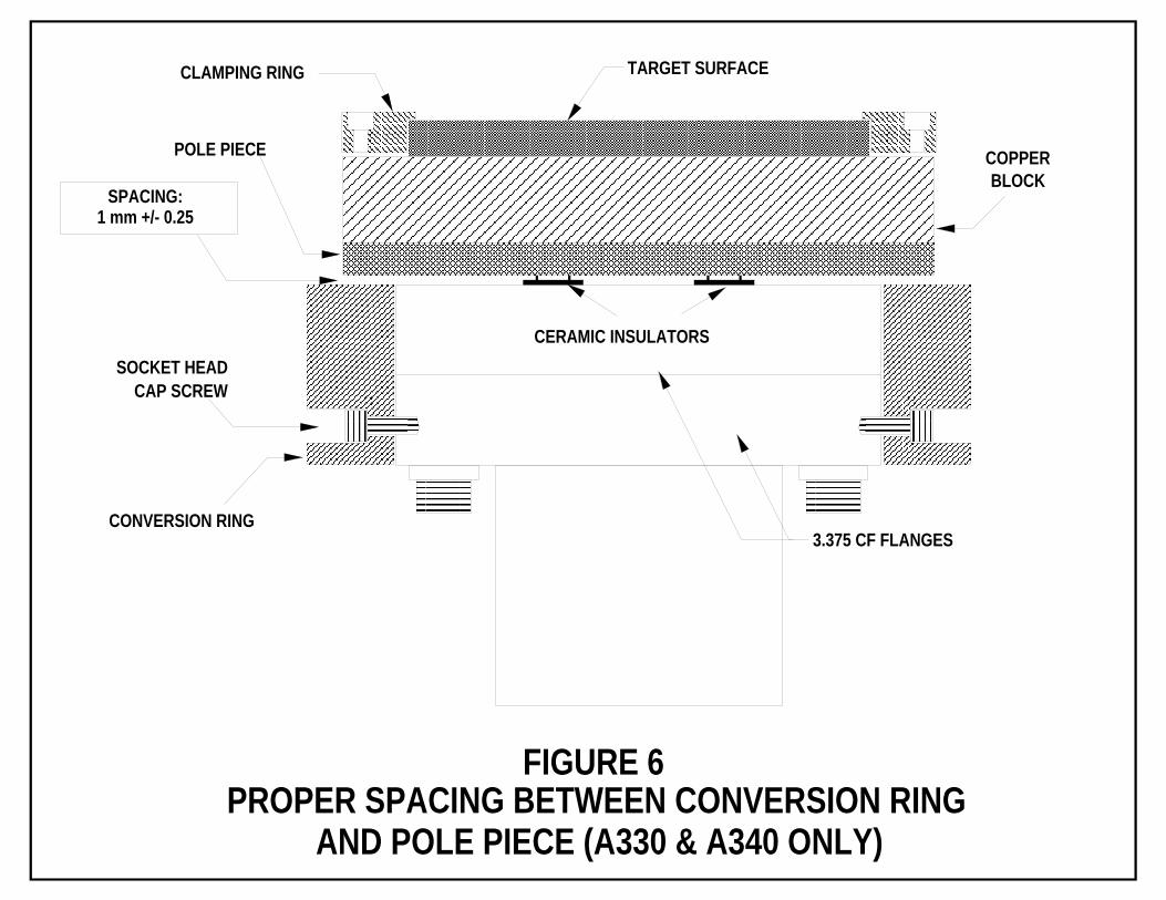
TIP: If target is to be operated at high power levels (> 50% of source rating), it may be desirable to utilize a thermal membrane between the cathode block and the back of the target to optimize heat transfer between the target and the water cooled copper cathode block. This is also a good idea when using target materials with poor thermal characteristics such as Cr. This thermal membrane material is available from AJA International in sheets which can be cut to size by the end user. It is important that the thickness of this material not exceed 0.3 mm (0.012") so as not to compromise the gap between the cathode and the ground shield. 5. Carefully tighten down clamping ring screws evenly to assure that the new target is flat against the copper cathode block. NOTE: With "reverse clamping ring" configurations, the magnetic target should be firmly, magnetically clamped to the cathode block and the clamping ring should be free to move a little under the machined step in the target. If the ring is not free, the step is too small and there will be no contact for cooling the target during operation. NOTE: Preferential heating on one side of the target during operation is usually indicative of a target which is not mounted flat against the cathode block or is "cocked". 6. Secure ground shield and ground shield screws taking care not to over tighten. 7. See Fig. 5. Be sure spacing between top of clamping ring and ground shield is: 0.75 - 2 mm (for operation at 0.5 to 30 mT) 0.75 - 1 mm (for operation at > 30 mT) WARNING: If spacing between clamping ring and ground shield (also known as the dark space "gap") is not correct for the operating pressure range, the operator can experience either shorting (if the "gap" is too small) or plasma within the "gap" (if it is too large). Shorting will prevent the user from even striking a plasma. Plasma within the "gap" will result in sputtering of the clamping ring material itself and frequent arcing as the plasma acts as a conductor between the cathode assembly and the ground shield. Adapter rings are available from AJA International to compensate for varying target thicknesses or situations where the target thickness is out of tolerance. NOTE: A330 and A340 sources utilize a conversion ring which supports the ground shield and maintains proper spacing (see Figs. 5 & 6). This conversion ring is held in place by (4) screws and should not be moved. If it is accidentally moved and the gap as shown in Fig. 6 must be reset, remove ground shield and readjust the conversion ring screws so that the conversion ring is parallel and concentric to the 3.375" CF flange nearest the pole piece. 8. With a multimeter, test between the ground shield and the target (or clamping ring for non- conducting targets) to assure discontinuity. B. Source Installation (See Figure 1) B1. Mounting CF, ISO or NW Flanged Sources (see B.2. for Sliding Seal Sources) a. If the complete source head can be inserted through the chamber port, please install and seal
using the appropriate metal gasket or o-ring. It is not necessary to disassemble shutter assembly, gas ring / shielding chimney, gas injection line, tilt gimbals or in-situ tilt drive assembly if your source has been supplied with these options as they will all fit through the chamber port intact. Proceed directly to section B.3. (POWER/WATER HOOK-UP).
b. If the port ID is smaller than head OD, remove the two electrical housing covers and carefully separate the electrical connection (bullet type or solder) to free the PTFE coated power cable from the coaxial connector. Remove the push-on water connectors from the ends of the PTFE tubing

-5-
and carefully slide the electrical housing end down and off of the PTFE tubing while gently pushing the PTFE tubing toward the source head to avoid pulling on the tubing.
WARNING: Do not pull on PTFE tubing ! Excessive pulling can compromise the seal integrity of the Swagelok water fittings, create small leaks and require extensive source tear-down.
c. Disconnect the Mini-CF seal at one end of the lower seal assembly's mounting stem and gently pull the source head (and tilt gimbals if supplied), PTFE tubes and power cable out and away from the lower seal assembly while gently pushing the PTFE tubing through the lower seal assembly's mounting stem. Place the source head in a safe, clean place where it cannot roll and fall to the floor. d. Now mount the lower seal assembly onto your chamber using the appropriate metal gasket or o-
ring. e. Slide a new OFHC copper Mini-CF gasket over the PTFE tubing and power cable and, from inside
the chamber, feed the power cable and PTFE tubing back through the Mini-CF and reseal the Mini-CF flange.
NOTE: If the integral shutter rod channel or integral gas injection channel are to be used, be sure the
source head is properly oriented before sealing the Mini-CF flange. The Mini-CF flange on the lower seal assembly is rotatable to make any orientation possible.
f. Re-attach electrical housing and power cable by reversing the procedure described in B.1.b. above
taking care not to pull on the PTFE tubing. Leave off one electrical housing cover until after POWER/WATER HOOKUP is complete to allow you to check for cooling water leaks.
g. Using a multimeter, test to assure discontinuity between electrical housing and both clamping ring
and center pin of coaxial connector. B2. Mounting Sliding Seal Sources (see Figure 1) a. Remove the two electrical housing covers and carefully separate the electrical connection (bullet type or solder) to free the PTFE coated power cable from the coaxial connector. Remove the push-on water connectors from the ends of the PTFE tubing and carefully slide the electrical housing end down and off of the PTFE tubing while pushing the PTFE tubing toward the
source. Using a hex keys, loosen the electrical housing clamp and shaft collar. Manually unscrew the compression nut of the sliding seal assembly and slide all parts off the end of the mounting stem, the power cable and the PTFE tubing and place the source head/mounting stem in a clean safe location where it cannot roll onto the floor.
WARNING: Do not pull on PTFE tubing ! Excessive pulling can compromise the seal integrity of the Swagelok water fittings, create small leaks and require extensive source tear-down.
b. Insert the sliding seal assembly into the hole in the chamber wall (or baseplate) as shown in Figure
1 with the chamber seal o-ring against the inside of the chamber wall (or baseplate). Tighten the mounting nut snugly taking care not to over tighten and strip the threads of the sliding seal assembly.
NOTE: The location of the shaft collar depends on source orientation in your chamber. Its purpose is to
prevent the source from moving due to gravity or differential pressure. When sputtering down or sideways, it should be located outside of vacuum. When sputtering up, it should be located inside vacuum. Always locate the shaft collar directly against the sliding seal assembly as shown in Figure 1.
c. If sputtering up, mount the shaft collar in the desired location, secure with a hex key, and insert the PTFE tubing, power cable and mounting stem through the hole in the sliding seal assembly. Carefully slide the compression o-ring, compression ring (counterbore facing source head) and compression nut over the end of the mounting stem in this order and tighten compression nut by

-6- hand to secure the compression seal. Do not use a wrench to tighten the compression nut as this is not necessary to make a good seal and may damage the threads on the sliding seal assembly. If sputtering down or sideways, insert the PTFE tubing, power cable and mounting stem through the hole in the sliding seal assembly. Carefully slide the compression o-ring, compression ring (counterbore facing source head) and compression nut over the end of the mounting stem in this order and tighten compression nut by hand to secure the compression seal. Do not use a wrench to tighten the compression nut as this is not necessary to make a good seal and may damage the threads on the sliding seal assembly. Now mount the shaft collar directly against the compression nut and secure with a hex key. d. Re-attach electrical housing and power cable by reversing the procedure described in B.2.a. above
taking care not to pull on the PTFE tubing. Leave off one electrical housing cover until after POWER/WATER HOOKUP is complete to allow you to check for cooling water leaks.
e. Using a multimeter, test to assure discontinuity between electrical housing and both clamping ring
and center pin of coaxial connector.
B3. Power/Water Hook-up (see Fig. 1) a. Connect either one of the PTFE tubing / push-on water connectors to a clean, reliable source of cooling water using at least 2 meters of non-conductive tubing (PTFE or Nylon) between the push- on connector and a grounded water supply line or closed loop chiller. NOTE: Since the cooling water is in contact with the copper cathode block, the water itself can act as a conductor between the cathode and ground. This can be confusing when checking for desired discontinuity between the cathode (or center pin of the coaxial connector) and ground. A 2 meter length of almost any cooling water within non-conductive tubing is sufficiently resistive to eliminate this problem. Your multimeter should display "Open Line" when checking for discontinuity. NOTE: WATER TEMPERATURE. Full power operation of any A300 Series sputtering source will only change the water temperature by a few degrees C. Therefore, the water inlet temperature can safely range from 5-35 degrees C. If your sputtering system will be operated in a humid environment, it is advisable to run with inlet water temperatures which are high enough to prevent condensation of water vapor on the Swagelok water fittings located inside the source's lower head assembly. If condensation builds up, it can allow arcs to develop between the electrically live areas and ground, causing source instability and eventually damaging internal source parts. Higher cooling water inlet temperatures may result in slightly elevated target surface temperatures which in most cases will only tend to nominally increase sputtering rate. NOTE: In locations where cooling water lines exhibit significant mineral deposits (which will eventually clog cooling lines), a filter or closed loop chiller is recommended. Do not exceed 60 psi cooling line pressure. b. Connect the other cooling line to an open drain (or chiller return) again using a 2 meter length of non-conductive tubing. NOTE: Always locate the cooling water valves upstream from the sputtering source. This ensures that, when not in use, the source cooling lines are not under pressure unnecessarily. c. Run recommended cooling water flow through lines for at least 30 minutes and observe to be sure there are no leaks. If cooling water is leaking from inside the source, consult factory for recommended procedure to correct this problem. Attempting to beak the main seal to correct this problem without consulting factory will void the source warranty. d. Using multimeter, test the integrity of your coaxial cable's center conductor. Although these cables look deceptively simple and foolproof, stretching the cable or accidentally stepping on the connectors can result in shorting the center conductor to the cable's ground shielding.

-7- NOTE: Be sure to use the cable provided with your power supply. RF coaxial cables (RG 225) which run from the matching network to the source's coaxial connector should be as short as possible (approximately 1 meter). Be aware that DC coaxial cables (RG 8 - typically supplied in 4 meter lengths) are too long and do not have sufficient high temperature capability to be used for RF operation. NOTE: RF APPLICATIONS ABOVE 250 WATTS. In most RF applications, the thermal limitations of the target material typically result in operation below 250 Watts. For these applications, the standard "N" type coaxial connector (attached to the source's internal power conductor cable by means of a bullet connector) is suitable and desirable since it can quickly be switched over to DC operation ("N" type connector is standard on DC cables). In some applications however, it is desirable to use RF power at above 250 Watts (reactive sputtering of metals or even Argon sputtering of metals with RF). In these applications special attention must be paid to the electrical connections on the source. For operation between 250 Watts and 600 Watts, it is recommended that a "C" type or "HN" type connector is used and that a hard solder connection may be better than using a bullet connector. For operation above 600 Watts, consult the factory for alternate configurations which will depend on material, source options, etc. e. Firmly push the male connector from you coaxial cable onto the mating female coaxial connector on the source's electrical housing end and tighten by hand. f. Again, using a multimeter, test to assure discontinuity between center pin on free end of cable and the electrical housing. g. Replace electrical housing cover(s) using 6-32 x 1/4 socket head cap screws. h. Connect the free end of your coaxial cable to your power supply (or matching unit - for RF use). IV. SOURCE OPERATION A. Pump down your chamber to an acceptable ultimate vacuum (usually less than 1 x 10⁻⁵ Torr) B. While reading pressure with a 1 Torr (or 100 mTorr), temperature compensated, capacitance manometer vacuum gauge, flow Argon gas with a metering valve or mass flow controller into the chamber to achieve a stable chamber pressure of approximately 10 mTorr (30 mT for RF). This can be achieved by a combination of gas flow or pump throttling. The optimum flow rate and/or throttle position are unique to each chamber and gas injection location. The user will have to experiment to find the most desirable plasma striking and operating settings. C. Initiate cooling water flow to recommended levels for the source. WARNING: It is highly recommended to interlock the cooling water flow to the power supply to prevent source operation without cooling water. D. FOR DC OPERATION, set power level setpoint on the power supply to 30 Watts. Push "START" button on power supply. Unless the is a shorting or connection problem, DC sources should strike a stable, torroidal plasma above the target surface. FOR RF OPERATION, the initial plasma strike with RF sources can be a little more involved. First, set the power level setpoint on the RF power supply to 30 Watts only. With your automatching network set in the "manual" mode, move the "load" and "tune" capacitors in their center positions. Now switch back to the "automatic" mode and then push the "RF ON" button on the RF power supply. If you do not strike a plasma, switch your automatching network back into the "manual" mode and attempt to minimize the reflected power reading by alternately moving the "load" and "tune" capacitors. If you strike a plasma using this method, now switch your automatching network back to "automatic" mode and observe the positions of your "load" and "tune" capacitors. If either capacitor is at its limit, a small matching network modification is recommended to approximately "center" the capacitors in the "matched" or "tuned" condition. If one ignores

-8- this situation, slight process condition changes may make it impossible to "match" since the capacitors may attempt to tune but are at their limit. Also, if have not yet been able to strike a plasma, the "matched" position is most likely beyond the limit of one of the capacitors. If it is necessary to modify the matching network (typically involves either removal of shunt capacitors or strapping the coil), follow the instructions provided with the RF equipment or contact the equipment manufacturer. WARNING: It is not necessary to exceed 30 Watts to strike a plasma with any A300 Series source. This is very important with RF sources. RF can couple into and heat internal source components if it is not being absorbed by the plasma. Do not run more than 30 Watts RF into a source without having a plasma for more than 1 minute at a time. RF operation without a plasma at 30 Watts will not damage source components. E. It is now possible to reduce operating pressure to the desired level. Depending on gas injection location, gas used, target material used, target condition and temperature, "voltage spike" capability of the power supply, the availability of some other electron source (such as a tungsten filament), etc., it may possible to strike the plasma at some lower pressure. This again will require some experimentation to determine the optimum procedure for your chamber. F. IMPORTANT NOTES ABOUT SOURCE OPERATION
NOTE: RATE / UNIFORMITY/ WORKING DISTANCE – Every system will require that the end user vary the following parameters to achieve the best possible films for his or her application:
a. Power – Approximately proportional to deposition rate. For a given power level, DC delivers higher rates than RF on conductive targets. Different target materials have different power limitations due to their heat transfer and thermal expansion characteristics. Overpowering a target can lead to de-bonding, melting, cracking and even source damage.
b. Working Distance – Rate has an inverse square relationship to working distance. Therefore,
doubling the working distance will reduce the rate by a factor of four. Recommended working distances are from 50 to 200 mm.
c. Pressure – Low operating pressures result in more energetic ion bombardment, more energetic,
less uniform depositions (fewer collisions on the way to the substrate), increased secondary electron bombardment of grounded or positively biased surfaces and increased film density. Higher operating pressures have the opposite effect.
d. Substrate Temperature – Increasing substrate temperature helps drive off surface contaminants
and reduces the probability of gases being incorporated into the film. Substrate heating is also used for substrate / film stress matching or intentional mismatching. This is only suitable for some substrates.
e. Substrate Motion – Substrate motion can be used to improve uniformity. The nature of the
substrate motion required is dependent on the location and size of the target and substrate relative to each other. It is possible for example to achieve 1% uniformity with a 2” sputter source on a 4 “ diameter substrate by using simple rotation with angled incidence sputtering. Contact factory for assistance with your application if this has not already been addressed.
NOTE: ELECTRON CURRENT & DISAPPEARING ANODES – The ion current impacting the target material is roughly proportional to the electron current draining to ground. Therefore, during extensive, high power operation (>20w/cm2) a significant electron current needs to find its way to ground as the plasma tries to remain net neutral. This effect can heat grounded surfaces and may require water cooled anode structures. If the deposition process involves reactive deposition of dielectric films with DC sputtering of a conductive target, the heavy deposition of the non-conducting film onto adjacent grounded surfaces will produce a “disappearing anode phenomenon” which, over time, can result in reduced deposition rates, plasma instability and deposition distribution changes and arcing. Dual magnetron AC sputtering seems to provide a

-9- solution to this problem for production applications. For research applications, special ground shields can be provided which have a greatly expanded grounded surface area.
NOTE: GAS INJECTION / SHIELDING CHIMNEY - Use of the optional integral gas injection / shielding chimney can reduce the chamber operating pressure to the lowest possible levels. This configuration produces higher differential pressures directly at the target surface while chamber pressures can be as low as 2 x 10⁻⁴ Torr depending on a number of conditions. NOTE: REACTIVE GAS SPUTTERING - Using a reactive gas in conjunction with Argon is sometimes desirable to deposit compound films (e.g. oxides, nitrides) at faster rates than are possible with compound targets. Ideally, Argon should be admitted near the target surface and the reactive gas should be admitted near the substrate surface. Achieving the desired stoichiometries can be difficult and the use of a partial pressure controller or an RGA can be very helpful in getting consistent results. Since the compound (eg. SiO2) is often non-conductive, the re-deposition of this non-conductive material onto a target which is being sputtered with DC (eg. doped Si) can create
islands which can charge up and ultimately create arcs. These islands may also “poison” the target and make it impossible to sputter with ordinary DC. In such situations it may be necessary to consider one or more of the following: (1) reduce the reactive gas percentage, (2) use a DC polarity inverter which pulses frequent (2-100 KHz) positive voltage to discharge these islands as they form, 3) use RF instead of DC, or 4) re-configure the gas introduction location(s) to reduce target poisoning. If reactive magnetron sputtering is being done with a non-conductive target, it can only be accomplished with RF.
NOTE: ARCING - Arcing is essentially a quick, localized draining to ground of an electron charge build-up. This drain to ground can happen through a flake of material, through the plasma (which is itself a conductor), or through air or vacuum at high powers or at short distances between cathode and ground. This intense burst of energy can heat or even vaporize grounded surfaces. This can damage both the source and the process. Therefore, to prevent arcing, it is first necessary to properly define its cause. Among the primary causes of arcing are: 1) flaking material shorting the cathode to the grounded parts of the source, 2) native oxide on a target’s surface (common with Al sputtering), 3) oxide or other non-conductive impurities within the target material, 4) distance between the cathode and ground being too small for the power level, 5) distance between the cathode and ground being too large, allowing a plasma to form within the source body (between cathode and ground) and this plasma providing a conductive path to ground for cathode electrons, 6) high target surface temperatures due to excess power for a given material or insufficient cooling. If operating in the DC mode, it is possible to produce an unstable condition which will appear as frequent arcing between the cathode (target) and ground shield. This is common with Aluminum targets or other conducting targets which quickly form a native oxide layer when exposed to air. If the target is of a reasonable purity (and assuming oxygen or water vapor are not being admitted into the chamber), this situation will stabilize within about two minutes as the native oxide layer is sputtered away. If stability is not achieved in a short time period, the cause of the arcing is more than just a native oxide issue and continued operation under these conditions will be detrimental to source condition and should be terminated. First check to be sure no flakes of target material are shorting the cathode to the ground shield. Be sure the target is within dimensional tolerances and that the target and the ground shield are properly installed to leave the appropriate gap between cathode and ground (0.75 and 3.0 mm depending on the source model, power level, operating pressure and magnetic field strength – call the factory to confirm correct values). Target impurity problems can be accommodated by sputtering with RF or polarity inversion DC up to some
power level. RF operation is not susceptible to "native oxide" charge-up and arcing since it is already suitable for sputtering other non-conducting materials. "Pulsed polarity inversion DC" is not suitable for non-conducting targets, however its frequent (2-100 KHz) polarity inversion (approximately + 50 Volts) helps discharge islands of native oxide charge build-up and suppress subsequent arcs. High target surface temperature will can cause undesired target expansion, bowing, delamination, shorting etc. The first thing to check is proper mounting to optimize heat transfer. It may also be that the target material’s thermal transfer properties are poor (eg. Cr) ultimately limiting the maximum power. Additional source changes can be made to optimize maximum level, but these changes usually compromise other aspects of the process, the hardware or serviceability.

-10- NOTE: RF CROSS-TALK BETWEEN MULTIPLE SOURCES - In co-deposition configurations where multiple RF powered sputtering sources are being employed simultaneously, a special power supply modification may be required to eliminate potential RF cross-talk and to facilitate stable matching. NOTE: NON-CONDUCTING TARGETS - Non-conducting targets will always require RF operation. The poor thermal conductivity of certain glass and ceramic targets will dictate a lower maximum allowable RF power. In order to minimize target cracking, it is recommended that RF power levels be slowly ramped up to, and particularly, down from the operating power level. Copper target “cups” and backing plates are also available for these types of target materials to ensure maximum thermal uniformity. NOTE: TARGET EROSION - Target erosion patterns (or erosion tracks) will depend on the magnet configuration employed to achieve the best deposition results on the substrate and whether one is sputtering with RF, DC or sputtering magnetic materials.. The RF erosion track will be closer to the outside of the target than the DC erosion track and the magnetic material erosion track will be above the point of magnetic saturation of the target material. The modular magnet array allows for many possibilities. Feel free to consult the factory on the best configuration for your application. The erosion track will eventually penetrate the target. Replace targets before penetration occurs. Failure to replace targets before penetration will result in sputtering of the backing plate or in some cases even the cathode itself possibly causing source damage. Utilization of a thermal membrane (available at a low cost from AJA International) provides an added measure of safety if one sputters through a target without a backing plate (not to mention that it optimizes thermal transfer). NOTE: MAXIMUM POWER LEVELS - BE CONSERVATIVE - Be conservative with the power setting when first using your AJA magnetron source with DC and especially with RF (carefully follow the procedures and heed the WARNING! statements in this manual). Fully understand the parameters and limitations of your equipment, target material and system before running at high power. This approach will prevent source, target and process damage and reduce operator frustration due to delayed operation. NOTE: UNBALANCED SPUTTERING / PLASMA STREAMS EMANATING FROM SOURCE - If source magnets are installed in an "unbalanced magnetron configuration" they can produce very dense films with excellent adhesion characteristics especially for metal films. The extended magnetic field generated by this configuration can produce what appears to be a plasma stream flowing away from the cathode. When several sources are used in a cluster arrangement for co-deposition, these streams can even appear to bend away from each other. Plasma streams are the result of electrons from the plasma, moving in the direction of diminishing magnetic field strength. They are also moving away from the plasma to compensate for the loss of ions toward the cathode. This occurs in all magnetron sputtering sources to some degree. The energy of these electrons and subsequent low energy ions which are created in this extended plasma and follow the electron flow is dependent on process pressure. At 1 mT, the energies can be as high as 25 eV. As process pressure is raised, the ionization potential drops with the concurrent reduction in electron energies. To further reduce electron energies and eliminate plasma streams, consult factory Do not equate the appearance or position of the plasma stream with the source's deposition profile. This is only showing the path of "charged species", not the primarily neutral sputtered material.
-11- V. MAGNET ARRAY MODIFICATIONS NOTE: All A300 Series sources are shipped with the "MAX RATE" magnet array configuration described below. A variety of configurations can be achieved with these sources producing different results and operating conditions. We recommend using symmetrical configurations such as those described below. WARNING: Modifying the magnet array must be done carefully, ideally on a workbench, in a vise with aluminum jaws or while the source is mounted to the system in an accessible configuration. The high strength, rare earth magnets can easily fly toward other magnets or magnetic materials if not handled carefully. Since these magnet materials may be brittle by nature, carelessness during this operation can result in broken magnets, unwanted magnet debris around the cathode or broken ceramic feedthroughs. Magnets and ceramic feedthrough breakage by the customer is not covered by the warranty. Also, the high field strength can easily destroy stored data on magnetic media (floppy and hard discs, calculators, digital micrometers, digital watches, etc.). Keep magnets away from these items. Finally, since these magnets can fly around easily, we highly recommend wearing eye protection when making these modifications. A. Modification Procedure - First remove all magnets, then reload desired configuration. TIP: Wear lint free cloth gloves for this procedure. 1. Remove ground shield, clamping ring, target and thermal membrane (if used). You can now see the top of the magnet stacks. You cannot remove them since they are strongly attracted to the pole piece halves. 2. Remove (4) counterbored screws holding (2) pole piece halves to bottom of copper cathode block. 3. Carefully position a suitable piece of magnetic material (another magnet stack, soft iron slug etc.) on top of the central magnet stack. Do this carefully to prevent the parts from flying together and damaging the magnets or the cathode block. 4. Using a sharp screwdriver, gently pry apart the (2) pole piece halves below the copper cathode block until the gap is approximately 1/4" wide. WARNING: If you pry the pole piece completely away from the back side of any magnet stack, this stack is now free to fly out of the cathode block hole and could be damaged. NOTE: The magnets are very strong. Take your time and do this carefully. Be aware that the cathode block is suspended above two ceramic feedthroughs. It is possible to break these feedthroughs if you do not follow the directions. 5. Now pull the central magnet stack away from the source by pulling the piece of magnetic material used in step 3. Carefully proceed to incrementally pry the pole pieces apart further reducing the contact area between magnet stacks and pole piece until each stack can be pulled out from the front side of the copper cathode block by a piece of magnetic material. Once removed, these stacks are best kept together in a long rod. This makes orientation obvious and prevents the stacks from flying together. Place the magnet stack in a safe place (ie. away from other magnets or magnetic materials). Remove central copper spacer (if used). 6. Once all magnets are removed, screw (2) pole piece halves behind cathode block and reassemble magnet array in desired configuration (see below). Begin with the central pieces.
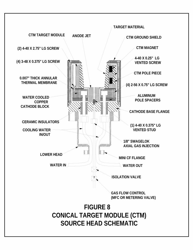
-12- "MAX RATE" CONFIGURATION (see Figure 4) The "MAX RATE" configuration is an unbalanced magnetron configuration which delivers high deposition rates, good uniformity and very dense films with excellent adhesion characteristics due to the low energy ion bombardment resulting from the extended magnetic field lines. "MAGNETIC MATERIAL" (see Figure 4) The "MAGNETIC MATERIAL" configuration is required to sputter thick magnetic material targets. A large, plated iron slug is used in the central location with full magnet stacks used in the peripheral locations. It is best to use NdFeB magnets (0.125" maximum Fe target thickness) in the peripheral locations. Expect magnetic material deposition profiles to be more peaked and deposition rates to be lower than for non-magnetic materials. This is due to the shunting of a large portion of the magnetic field by the target material. TIP: When sputtering magnetic materials, flakes of magnetic debris can be attracted to the cathode block, particularly on top of the magnets or on the outer edges of the pole pieces. These must be removed using a small stack of rare earth cleaning magnets held in a plastic bag. Bringing these bagged cleaning magnets into contact with the magnetic debris will remove them from the cathode block and pole piece edges. Periodically the plastic bag can be separated from the cleaning magnets to discard the magnetic debris. "BALANCED HIGH & MEDIUM RATE" CONFIGURATIONS (see Figure 4) The "BALANCED HIGH RATE CONFIGURATION" is exactly the same as the "MAGNETIC MATERIAL" configuration except that it is now being used for non-magnetic targets. Consequently, no magnetic field lines are shunted by the target material. Contrary to the "MAX RATE" configuration, this arrangement results in a wider erosion track but with no sputtering of the target center and eliminates the extended magnetic field lines. Uniformity will be somewhat enhanced while film density will be reduced. In applications with temperature sensitive substrates, this may be the best choice since the flux and energy of charged species impinging on the substrate is significantly reduced. The "BALANCED MEDIUM RATE" configuration is similar but will result in lower rates for applications where precise control is required in depositing very thin films and multi-layers with minimum surface disturbances by charged particles. "LOW BIAS" CONFIGURATION (see Figure 4) This near balanced configuration further reduces the energy of the electrons moving from the plasma toward the substrate to as low as a few eV depending on operating pressure. This configuration also reduces plasma streaming, reduces the deposition rate and reduces film density. It is ideal for coatings on plastic films or discrete thin film multi-layer growth. VI. CTM MODULE CONFIGURATIONS A. Applications 1. The CTM (conical target module) configuration (see Fig. 8) is utilized for two primary purposes: a. Efficient off-axis sputtering. The target material in this application should have a 5 degree taper which is wider at the open end of the source. b. Very thin, discrete multi-layers which can be deposited without the damage imposed by high energy reflected neutrals. The target material in this application should be cylindrical in geometry or even have a 5 degree taper which is wider at the bottom of the source.

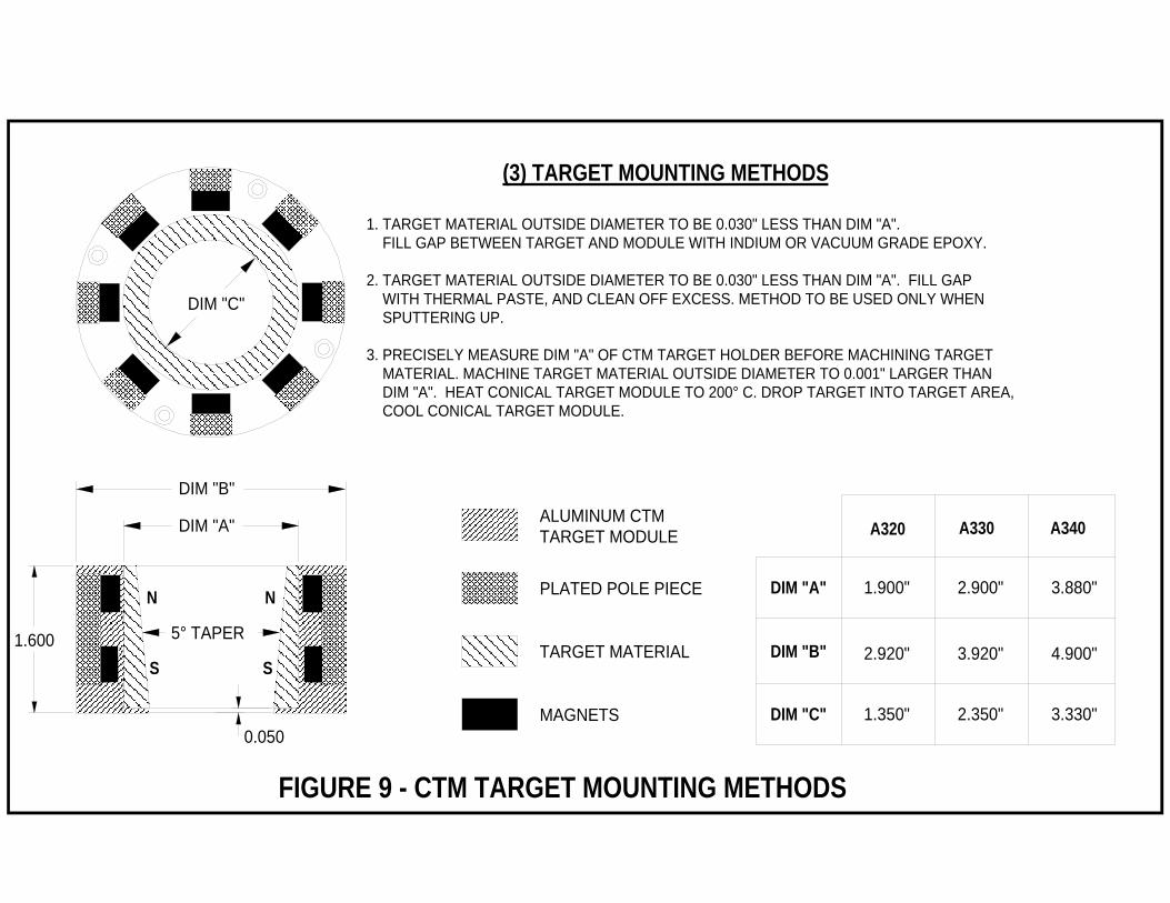
-13- B. Converting a planar source to the CTM configuration (If source is already supplied in the CTM configuration, go directly to section VI.C. in this manual) NOTE: In order to convert a planar source to the CTM configuration, the flange of the array block must already be modified to allow axial gas injection through the base of the array block flange (see Fig. 8). If this modification has not been done, the source must be returned to AJA for modification. This modification incorporates a 1/8" gas line which runs from inside the source head, parallel to the cooling lines, and out the end of the source's electrical housing. In the planar configuration, this 1/8" gas introduction line should be valved off and not be used for gas introduction as it may create a high pressure plasma in the source's dark space gap and subsequently damage the source and/or compromise source operation. 1. Remove ground shield (2 screws), clamping ring (4 screws), target, magnets, copper spacer and pole pieces (4 screws). This leaves only the water cooled, copper cathode block suspended above its base flange by (2) 1/4" stainless steel water tubes. 2. Attach anode jet through center hole in copper cathode block utilizing vented 4-40 x 0.375" LG vented stud. Tighten by hand until bottom of anode jet touches base flange. 3. Secure (2) aluminum pole spacers under copper cathode block with (4) 2-56 x 0.75" LG screws. 4. Attach CTM target holder assembly to copper cathode block with (4) 3-48 x 0.375" LG screws. An annular ring of thermal membrane material should be sandwiched between the CTM target holder and the copper cathode block to assure optimal heat transfer between the water cooled cathode block and the aluminum CTM target holder. Methods to load and secure target material into the CTM target holder are described below and in Figure 9. 5. Finally attach CTM ground shield using (2) 4-40 x 2.75" LG screws. C. CTM Target Module Loading and Installation Procedure (see Fig 8) 1. Remove (2) 4-40 x 2.75" LG screws and ground shield. 2. Remove CTM Target Module with (4) 3-48 x 0.375" LG screws and annular thermal membrane. 3. Place CTM module on a clean work surface and carefully remove (8) oval, nickel plated, pole pieces with magnets attached by removing 4-40 x 0.25" LG vented screws. Magnets are oriented as follows (See Figure 9): Upper level (near open end of target) magnets have North orientation facing the gun's central axis. Lower level (near anode jet gas inlet) magnets have South orientation facing the gun's central axis. WARNING: Rare earth magnets are very strong. Take care not to let magnet/pole piece assemblies fly toward each other as this can damage magnets. Also do not place magnets near electronic devices or magnetic debris or contamination during this procedure. 4. Load target material using recommended procedure (see Figure 9). 5. CTM targets and bonding service are available from AJA International. Depending on material, targets can be either bonded (Silver epoxy or indium), thermal paste mounted, or press fit into a heated CTM target holder. It may be worthwhile to call AJA International for recommended target mounting methods for specific materials. 6. Target material OD should typically be undersized by 0.030" for indium bonding, Silver epoxy bonding or thermal paste mounting and 0.001" oversized for press fit / heated CTM target holder mounting. (See Figure 9)

-14- 7. Reverse procedure described above and reassemble source. Remember to install annular thermal membrane between CTM target module and copper cathode block and to tighten down all screws evenly to keep top of CTM target module parallel to top of CTM ground shield. D. CTM Source installation/operation. 1. The CTM source should be installed and operated in the same manner as the standard planar source (see sections III.B.1., III.B.2., III.B.3. and IV. in this manual) with the single exception that the Argon gas is to be admitted into the chamber via the CTM's 1/8" gas introduction line. The CTM's gas introduction line must be fitted with an isolation valve and a gas flow control device (MFC or metering valve) both of which are to be located external to the source (see Figure 8). NOTE: Process gases other than argon (ie. O2,N2) may be added to the argon gas via the 1/8" gas introduction line depending on process requirements. Be aware that injecting reactive gases via the 1/8" CTM gas line may however "poison" the target surface and reduce deposition rate or even prevent sputtering altogether. In this case, a gas ring at the substrate surface may be more suitable for admitting the reactive gas. VII. A3CV CONFIGURATIONS A. Design Concept / Target Modules
1. The A3CV (acronym for “A300 Convertible”) configuration (see Fig. 10 and Fig. 11) is a special version of the A300 Series Sources designed to accommodate multiple target sizes with a single source. This is accomplished by having a common A3CV subassembly fitted with a variety of target modules:
a. Mechanically clamped (with clamping ring) for 1” - 4” diameter and 1” x 2” rectangular or 2” x 2”
square targets. b. Magnetically clamped targets for 1” - 4” diameter and 1” x 2” rectangular or 2” x 2” square magnetic
material targets. The cost of any target module is about 25% of the price of the source. Therefore, a customer can obtain a source with three different target modules for approximately 1.5x the cost of a typical source.
B. Installation and Operation Differences (see Fig. 10 and Fig. 11)
In general, the A3CV is very similar to other A300 sources with a few exceptions. Review the A3CV and A300 schematics carefully and familiarize yourself with the basic differences described below:
1. All Configurations
a. The electrically isolated, water-cooled, cathode block is located below the pole piece and magnet array block and acts as a large thermal mass to cool the entire cathode / target assembly. Three thermal membranes are sandwiched between cathode block / pole piece / magnet array block / target to provide optimum heat transfer with excellent outgassing capability. Use of this thermal membrane material is absolutely required to ensure magnet and source integrity.
b. The lower ground shield is fixed to the lower head assembly by two flat, countersunk, socket head
cap screws with tapered washers.
c. The gas injection chimney is a one piece unit that admits process gas via 6 peripheral holes. d. The gas injection chimney is a cylindrical, thick walled part with (4) tapped holes in the end to
accommodate an orifice plate.

-15-
e. If the source is converted between mechanically clamped and magnetically clamped configurations, the total length of the source head and gas injection chimney will vary by the thickness of the ground shield top ring.
2. Mechanically Clamped Configurations (using clamping ring)
a. The ground shield top ring (and gas chimney, if used) attach to the lower ground shield by means of two 4-40 screws.
3. Magnetically Clamped Configurations
a. A ground shield top ring is not used at all. The gas injection chimney can be attached directly to the lower ground shield if the application warrants its use.
When you are comfortable with the aforementioned, unique aspects of your A3CV source, please follow the normal installation, operation and magnet modification procedures for A300 sources. C. Who benefits from A3CV flexibility?
1. The flexibility afforded by the A3CV source is ideal for customers:
a. utilizing both common and precious materials. b. utilizing a combination of magnetic and non-magnetic materials.
c. having a variety of target sizes on hand or making their own targets.
d. who begin with small targets / substrates but wish to upgrade to larger targets / substrates in the
future. e. wishing to sputter from unusual target geometries.
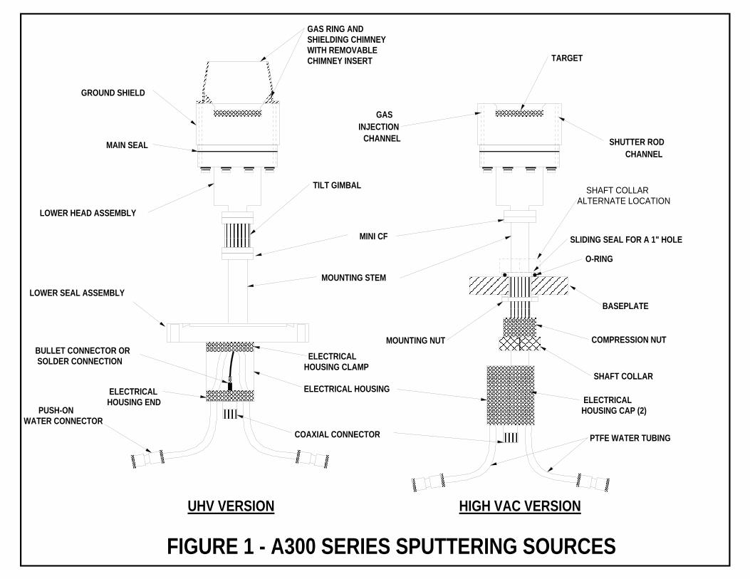
GROUND SHIELD
LOWER HEAD ASSEMBLY
MAIN SEAL
ELECTRICAL HOUSING
LOWER SEAL ASSEMBLYBASEPLATE
SHUTTER RODCHANNEL
HIGH VAC VERSIONUHV VERSION
TILT GIMBAL
MINI CF SLIDING SEAL FOR A 1" HOLE
SHAFT COLLAR
COMPRESSION NUT
O-RING
MOUNTING NUT
GAS RING ANDSHIELDING CHIMNEYWITH REMOVABLE CHIMNEY INSERT TARGET
GASINJECTION
CHANNEL
FIGURE 1 - A300 SERIES SPUTTERING SOURCES
SHAFT COLLARALTERNATE LOCATION
MOUNTING STEM
COAXIAL CONNECTOR PTFE WATER TUBING
PUSH-ON WATER CONNECTOR
BULLET CONNECTOR OR SOLDER CONNECTION ELECTRICAL
HOUSING CLAMP
ELECTRICAL HOUSING END ELECTRICAL
HOUSING CAP (2)

TARGET
CLAMPING RING
MAIN SEAL
GROUND SHIELDCOPPER CATHODE BLOCK
POLE PIECE (SPLIT)
SWAGELOK FITTINGS
CERAMIC INSULATORS
ELECTRICAL CONNECTION
WITH INTEGRAL WATERCOOLING CHANNEL
FIGURE 2 - A300 SOURCE HEAD DETAIL
PLASTIC SHIPPING SHIM(REMOVE BEFORE USE) STEPPED
MAGNETIC TARGET
REVERSE CLAMPING RING GROUND SHIELD
POLE PIECE (SPLIT)
CERAMIC INSULATORS
ELECTRICAL CONNECTION
CONVERSION SING
CERAMIC BALLSTABLIZERS
A320 SHOWN A340 SHOWN
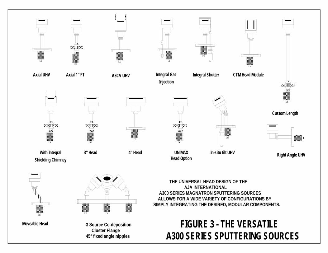
Moveable Head
Axial UHV Axial 1" FT Integral GasInjection
Integral Shutter CTM Head Module
Custom Length
With IntegralShielding Chimney
3" Head 4" Head UNIMAXHead Option
In-situ tilt UHV
3 Source Co-deposition Cluster Flange45° fixed angle nipples
THE UNIVERSAL HEAD DESIGN OF THE AJA INTERNATIONAL A300 SERIES MAGNATRON SPUTTERING SOURCES ALLOWS FOR A WIDE VARIETY OF CONFIGURATIONS BY SIMPLY INTEGRATING THE DESIRED, MODULAR COMPONENTS.
Right Angle UHV
A3CV UHV
FIGURE 3 - THE VERSATILE A300 SERIES SPUTTERING SOURCES

RARE EARTHMAGNET
PLATEDIRON
OFHC COPPER
WATERCHANNEL
LINESMAGNETIC FIELD
TARGETFe
LOW BIAS CONFIGURATION
MAGNETIC MATERIALSCONFIGURATION
MAX RATE CONFIGURATION
CONFIGURATION
(UNBALANCED)
BALANCED HIGH RATE
CONFIGURATIONBALANCED MED. RATE(LOW RATE,NEARLY BALANCED)
FIGURE 4 - MAGNET ARRAY MODIFICATIONS
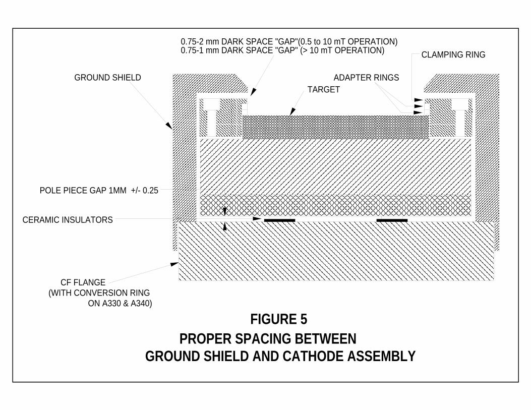
FIGURE 5 PROPER SPACING BETWEEN GROUND SHIELD AND CATHODE ASSEMBLY
GROUND SHIELD
CF FLANGE
0.75-2 mm DARK SPACE "GAP"(0.5 to 10 mT OPERATION)
POLE PIECE GAP 1MM +/- 0.25
(WITH CONVERSION RING ON A330 & A340)
0.75-1 mm DARK SPACE "GAP" (> 10 mT OPERATION)
TARGET
CLAMPING RING
ADAPTER RINGS
CERAMIC INSULATORS
CERAMIC INSULATORS
CONVERSION RING
POLE PIECE
3.375 CF FLANGES
COPPERBLOCK
CLAMPING RING
SPACING:1 mm +/- 0.25
SOCKET HEADCAP SCREW
TARGET SURFACE
FIGURE 6PROPER SPACING BETWEEN CONVERSION RING
AND POLE PIECE (A330 & A340 ONLY)
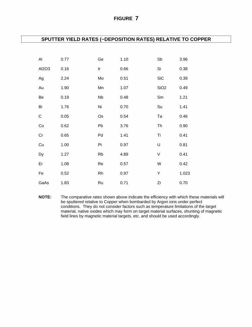
FIGURE 7
SPUTTER YIELD RATES (~DEPOSITION RATES) RELATIVE TO COPPER Al 0.77 Ge 1.10 Sb 3.96 Al2O3 0.16 Ir 0.66 Si 0.38 Ag 2.24 Mo 0.51 SiC 0.39 Au 1.90 Mn 1.07 SiO2 0.49 Be 0.19 Nb 0.48 Sm 1.21 Bi 1.76 Ni 0.70 Su 1.41 C 0.05 Os 0.54 Ta 0.46 Co 0.62 Pb 3.76 Th 0.90 Cr 0.65 Pd 1.41 Ti 0.41 Cu 1.00 Pt 0.97 U 0.81 Dy 1.27 Rb 4.89 V 0.41 Er 1.08 Re 0.57 W 0.42 Fe 0.52 Rh 0.97 Y 1.023 GaAs 1.83 Ru 0.71 Zr 0.70 NOTE: The comparative rates shown above indicate the efficiency with which these materials will be sputtered relative to Copper when bombarded by Argon ions under perfect conditions. They do not consider factors such as temperature limitations of the target material, native oxides which may form on target material surfaces, shunting of magnetic field lines by magnetic material targets, etc. and should be used accordingly.
TARGET MATERIAL
CTM GROUND SHIELD
CTM POLE PIECE
4-40 X 0.25" LGVENTED SCREW
ALUMINUMPOLE SPACERS
CATHODE BASE FLANGE
MINI CF FLANGE
1/8" SWAGELOKAXIAL GAS INJECTION
(1) 4-40 X 0.375" LG VENTED STUD
(4) 2-56 X 0.75" LG SCREW
GAS FLOW CONTROL(MFC OR METERING VALVE)
ISOLATION VALVE
CTM MAGNET
ANODE JET
CERAMIC INSULATORS
(4) 3-48 X 0.375" LG SCREW
WATER OUTWATER IN
(2) 4-40 X 2.75" LG SCREW
CTM TARGET MODULE
WATER COOLED COPPER
CATHODE BLOCK
0.007" THICK ANNULARTHERMAL MEMBRANE
LOWER HEAD
COOLING WATER IN/OUT
FIGURE 8CONICAL TARGET MODULE (CTM)
SOURCE HEAD SCHEMATIC
PLATED POLE PIECE
TARGET MATERIAL
MAGNETS
1.900"
2.920" 3.920"
2.900" 3.880"
A330A320 A340
DIM "A"
DIM "B"
DIM "C" 1.350" 2.350" 3.330"
FIGURE 9 - CTM TARGET MOUNTING METHODS
DIM "A"
DIM "B"
1.600 5° TAPER
0.050
DIM "C"
S
N
S
N
1. TARGET MATERIAL OUTSIDE DIAMETER TO BE 0.030" LESS THAN DIM "A". FILL GAP BETWEEN TARGET AND MODULE WITH INDIUM OR VACUUM GRADE EPOXY.
2. TARGET MATERIAL OUTSIDE DIAMETER TO BE 0.030" LESS THAN DIM "A". FILL GAP WITH THERMAL PASTE, AND CLEAN OFF EXCESS. METHOD TO BE USED ONLY WHEN SPUTTERING UP.
3. PRECISELY MEASURE DIM "A" OF CTM TARGET HOLDER BEFORE MACHINING TARGET MATERIAL. MACHINE TARGET MATERIAL OUTSIDE DIAMETER TO 0.001" LARGER THAN DIM "A". HEAT CONICAL TARGET MODULE TO 200° C. DROP TARGET INTO TARGET AREA, COOL CONICAL TARGET MODULE.
(3) TARGET MOUNTING METHODS
ALUMINUM CTM TARGET MODULE
4.900"