Embed Size (px)
Citation preview

FD4
Final Diploma Infringement and Validity FD4
Tuesday 10 October 2017 10:00 to 15:00
INSTRUCTIONS TO CANDIDATES 1. The whole assessment task is to be attempted. 2. The total number of marks available for this paper is 100. 3. Start each part of your answer on a new sheet of paper. 4. Write your answers on alternate lines. 5. Do not state your name anywhere in the answers. 6. Write clearly, as examiners cannot award marks to answer scripts that cannot
be read. 7. The scripts may be photocopied for marking purposes.
a) Use only black ink. b) Write on one side of the paper only. c) Write within the printed margins. d) Do not use highlighter pens on your answer script.
8. Instructions on what to do at the end of the examination are on the Candidate Cover Sheet.
9. Any candidate script removed from the examination room will not be marked. 10. This question paper consists of 17 sheets, including this sheet, and
comprises: Assessment task (1 sheet) Client letter (1 sheet) Document A (7 sheets) Document B (3 sheets) Document C (1 sheet) Document D (3 sheets).

Page 1 of 16
FD4
Assessment task Your client sends you the letter and documents listed on the Instructions to Candidates. Your task is to prepare advice to your client on whether the attached granted patent may be enforced and defended. You should prepare notes on which you would base your advice in which you:
a) Provide an opinion on infringement and validity, in the UK only. b) Identify other patent-related legal issues pertinent to the facts presented. c) Outline possible actions that may be taken to strengthen your client’s legal
position. d) Summarise the opinions formed in a) to c) above.
Note the following:
a) You should accept the facts given to you and base your answer on those facts.
b) You should not make use of any other special knowledge that you may have of the subject matter concerned.
Total: 100 marks

Page 2 of 16
FD4
Client letter Dear Attorney, Thank you for your time on the telephone just now. It was a pleasure to talk to someone that 5 finally seems to want to help. As I mentioned to you, my company, Flame Out Limited, makes fire suppression systems for buildings. These systems comprise a series of sprinklers, which are usually mounted to the ceiling of a room. In the event of a fire the sprinklers automatically activate to cause water to 10 be expelled therefrom to seek to douse the fire. My company has been very successful because our sprinklers have a very fast reaction time (the reaction time being measured from the time the temperature in a room exceeds a critical value to the time of activation of the sprinkler) and hence are rightly considered to be the 15 best in the business. The most important aspect of our sprinkler system is our glass bulb, which is the subject of our patent (Document A). The aspects of the frame are all commonplace and are industry standard. The patent is actually in the name of my brother, which I am sure does not matter for present 20 purposes because he agreed to sell it to me a few years ago when he left the business. My company is the exclusive licensee under the patent. As I think I mentioned to you, my brother and I fell out just before he exited the business and I was shocked to see him resurface as part of a new start-up company (Bulb-Us) which has 25 started to sell rival commercial products. I attach a copy of his press release (Document B). We have obtained samples of the ‘Sprinkl-eeze Pro’ sprinkler head with a glass bulb as shown and can confirm that it is identical to that shown in the press release. My guess is that the bulbs are very cheap to make because they use water and a solid plastic plug. As he sells his bulbs for the same price as ours his margins will be larger. 30 I certainly do not want to go to war with my brother’s company but we have started to notice a significant dip in sales, which I assume to be due to Bulb-Us’s product gaining more traction, and so I need you to take action on our behalf before the damage ruins us. 35 I see that he also sells to the domestic market. No matter what the press release says, this is such a tiny market that it is of no interest to our company. Thank you for agreeing to see me next week. To help frame our discussions I asked our technical people to check if Bulb-Us have a patent or patent application. Apparently they do 40 but it is not yet published and so there are no details. Our technical people also found the two further documents which should help us destroy Bulb-Us’s patents in due course (Documents C and D). As an aside, we have checked with Big Bulbs and they have confirmed that the bespoke bulb was never launched. 45 I look forward to seeing you next week. Kind regards Cas M. de Pompiers 50

Document A
Page 3 of 16
FD4
Granted British Patent GB 2123456
(Filed March 2012, Granted September 2016)
Sprinklers
This invention relates to sprinklers, and specifically sprinklers comprising thermally responsive
frangible bulbs.
Automatic fire sprinklers (nozzles) have a frame with an outlet at one end, an orifice which is usually 5
just upstream of the outlet, and an inlet which is connectable to a source of fire retarding fluid under
pressure. The outlet is secured in the normally closed or sealed position by a cap or valve; the cap or
valve being held in place by a thermally responsive element which is releasable when its temperature
is increased from a normal ambient condition to an operating temperature, by the heat from a fire. Upon
release of the thermally responsive element, a stream of fire retarding fluid rushes from the outlet 10
towards a deflector, which is mounted on the frame at the opposite end from the outlet, and is distributed
over the area to be protected by the sprinkler (nozzle) from fire.
The two primary types of thermally responsive elements used to automatically release fire sprinklers
are fusible solder links and frangible glass bulbs. Although satisfactory, fusible solder links have 15
generally fallen out of favour and have been replaced by frangible, or breakable, glass bulbs.
Over time it has become possible to reduce the size of the frangible glass elements and the frames of
automatic fire sprinklers. However, the principles concerning the method of operation of frangible glass
bulbs as well as the advantages of their use have remained essentially the same. 20
The successful use of frangible glass bulbs, as thermally responsive elements for automatic fire
sprinklers, requires a bulb of a particular strength, which can withstand ambient environmental
conditions but which can be easily and readily broken as it heats. Such bulbs typically contain a liquid,
and the thermophysical properties of the liquid used to fill the glass shell are key to the performance of 25
the bulb.
Of course, it is desirable to have the glass bulb break as soon as a fire occurs so that the sprinkler system
is activated as soon as possible. However, it is also desirable for the glass bulb to only break when it is
certain that a fire has occurred rather than there being a change in the environmental temperature. 30

Document A
Page 4 of 16
FD4
It is an object of the invention to provide a sprinkler system having an improved thermally responsive
frangible bulb and to an improved glass bulb.
A first aspect of the invention relates to a sprinkler system in accordance with Claim 1.
5
Advantageously, by using two different species within the bulb, the active range, sensitivity and
responsiveness of the bulb can be increased and/or tuned to specific needs and requirements whilst
showing the quick actuation times specified.
The actuation time is measured as the time taken for a thermally responsive member to break when 10
exposed to a particular temperature, i.e. by suddenly exposing a thermally responsive member to an
environment with a temperature of X °C, the actuation time is the time it takes for the thermally
responsive member to break.
Preferably, the actuation time is less than 10 s at 75 °C and less than 5 s at 120 °C. For example, an 15
actuation time of 9 s at 75 °C and an actuation time of 4 s at 120 °C.
The first species may be a fluid and the second species may be a liquid, preferably the first species and
second species are immiscible liquids.
20
Because the liquids are preferably immiscible (i.e. they do not mix) it is possible to accurately control
the overall operating characteristics and to provide a broad range of operating criteria. This is because
liquids are practically incompressible and so two immiscible liquids act as two separate systems within
the closed environment provided by the bulb. We have surprisingly found that the use of immiscible
liquids leads to a better response time. 25
The first liquid may have a boiling point and/or density less than that of the second liquid. This means
that one fluid will float on the other. In practice, this means that the heavier fluid (which may boil at a
higher temperature) will probably be closer to the fire or heat source as the temperature rises.
30
Where the second species has a density greater than the first species (and has a higher boiling point),
we prefer the second species to take up more volume than the first species within the thermally
responsive element.
The thermally responsive member is preferably a glass bulb with an upper pointed end and a lower 35
rounded end; the upper pointed end being for accommodating an air bubble. The pointed end is provided
to give the bulb an installation direction (pointed end up) and accommodates the air bubble (which is

Document A
Page 5 of 16
FD4
impossible in practice to avoid) so that the air bubble does not interfere with the fluids. In any case, the
air bubble is small and so does not affect the response time of the sprinkler system.
The glass bulb preferably has a wall between the two ends, which wall is thinner than the lower rounded
end. The wall should be sufficiently thick that it does not break in use but sufficiently thin to be able to 5
break as the pressure rises. A thick bottom portion may be more effective at transferring heat to the
fluids within the glass bulb.
Any fluids known from the prior art may be used within the sprinkler as will be appreciated by the
addressee. Preferably, the fluids, in combination, will offer the combination of properties needed to 10
achieve quick response operating characteristics in cost-effective frangible glass bulbs having a nominal
operating temperature of at least up to 90 °C and, preferably at least up to 130 °C.
Although the technical choice of suitable liquids for fast response sprinkler bulbs should be based on
consideration of thermophysical properties such as compressibility, thermal expansivity and thermal 15
conductivity, the data available for candidate liquids is sparse, often dubious and rarely in the
pressure/temperature regime of a sprinkler bulb at operation. It is not possible to accurately predict
performance as a bulb filling liquid based on incomplete or contentious literature values. Practically no
independent empirical measures exist of important liquid properties such as the dP/dT ratio, which
defines the relationship between bulb operating temperature and sensitivity. The choice of the most 20
suitable liquid depends on an extensive empirical testing programme.
The preferred liquids contained in the glass bulbs (CH and DMF) are readily available and represent a
reduced level of toxicity in comparison with previously used substances. More particularly, the cost of
relatively expensive species can be controlled by substituting for low cost co-liquids. 25
An embodiment of the invention will now be described, by way of example only, with reference to the
accompanying drawings, in which:
FIG. 1 is a partial sectional view of an automatic fire sprinkler showing a preferred embodiment 30
of the quick response, frangible glass bulb, thermally responsive element of this invention; and
FIG. 2 is an enlarged, axial, cross-sectional view of the quick response, frangible glass bulb of
this invention taken along the line A-A of FIG. 1.
With reference to FIG. 1, automatic fire sprinklers (nozzles) of this invention have a frame 1 with an 35
outlet 2 at one end, an orifice 3 which is usually just upstream of the outlet 2, and an inlet 4 which is
Document A
Page 6 of 16
FD4
connectable to a source of fire retarding fluid (also known as extinguishant) under pressure. The outlet
2 is secured in the normally closed or sealed position by a cap 5, the cap 5 being held in place by a
thermally responsive element 6 which is secured in position by bulb assembly screw 7. Upon release of
the thermally responsive element 6, a stream of fire retarding fluid (typically water) rushes from the
outlet towards a deflector 8, which is connected to the frame 1 at the opposite end from the outlet 2, and 5
is distributed over the area to be protected by the sprinkler (nozzle) from fire. Clearly, the frame 1 will
usually be mounted to a ceiling (not shown) with the frame 1 depending below.
With reference to FIG. 2, the thermally responsive element 6 of this invention is comprised of a
frangible glass bulb 6A being itself comprised of a shell 9 and a fluid 10 which nearly completely fills 10
the interior space 11 of the shell 9, except for a relatively small glass pocket in which a gas bubble 12
resides. With further reference to FIG. 2, the shell 9 of the frangible glass bulb of this invention consists
of a central region R1 which has a uniform outer diameter D1, a spherical end region R2, and a stem
end region R3, the spherical end region having a seat of diameter D2 and the stem end region R3 having
a seat of diameter D3, the distance between the spherical end seat and the stem end seat being length L. 15
The gas bubble 12 resides in the spherical end region R2 as shown but when installed (stem end
uppermost) will fill the stem end region R3.The gas bubble 12 represents a third fluid within the
thermally responsive element 6. Whilst it would be advantageous to not have present the gas bubble 12,
it is in practice very difficult, if not impossible, to avoid due to filling and sealing technologies used to
prepare the thermally responsive element 6. 20
In the preferred embodiment of this invention, the frangible glass bulb 6A is of the quick response type
with a diameter D1 of from about 2 mm to about 3 mm, a diameter D2 of up to about 2.5 mm, a diameter
D3 of up to about 2.2 mm, and a length L of from about 12 mm to about 24 mm, the diameters D2 and
D3 being in proportion to diameter D1. The shell 9 of the frangible glass bulb 6A is almost completely 25
filled by an activating fluid 10.
The activating fluid 10 comprises a first liquid 10A and a second liquid 10B. The liquids 10A, 10B are
immiscible and there is a clear boundary 10C between them.
30
The fist liquid 10A has a lower density than the second liquid 10B and so lies above it, with the frangible
glass bulb 6A oriented vertically and in its correct position within the sprinkler. The air bubble 12 is
above the first liquid 10A and will be accommodated in the stem end region R3.
In a preferred embodiment, the first liquid 10A is cyclohexane (CH) and the second liquid 10B is 35
dimethylformamide (DMF). A table of properties is provided below:

Document A
Page 7 of 16
FD4
Liquid Boiling Point
(°C)
Density
(g/cm)
Heat Capacity
(J/K/cm3)
Thermal Expansion
(cm/K)
dP/dT
(Bar/K)
CH 81 0.779 1.4 0.0018 9.17
DMF 153 0.944 1.9 0.00104 13.82
Of these characteristics, the key ones are the boiling point, thermal expansion (i.e. the amount the
species increases in size as it heats up) and the rate of change of pressure with temperature (dP/dT).
We have surprisingly found that by providing two separate liquids 10A, 10B we can tune the operating
temperature and actuation time of the frangible glass bulb 6A so that it can activate quickly in the event 5
of a fire.
As heat is transferred to the liquids 10A, 10B via the walls of the frangible glass bulb 6A the fluids start
to heat and expand, thereby increasing the internal pressure within the frangible glass bulb. If the fluid
is too expansive and with too low a boiling point it can cause premature breakage, which means that 10
fire extinguishing fluid may be expelled before it was desired. In some systems this can lead to a
reduction in the pressure of the water or other extinguishant, which can deleterious. By using two liquids
the overall expansivity (and actuation temperature) can be controlled and the frangible glass bulb 6A is
more resilient to temporary thermal shocks, which should not activate the sprinkler system.
15
Because the liquids are immiscible, each acts as a separate system and each may be capable of quickly
activating the bulb 6A. In the present case, a smouldering (relatively low temperature) fire or heat source
can heat the first liquid 10A sufficiently to cause the frangible glass bulb 6A to break. Alternatively, a
flash (relatively hot) fire or heat source can cause the second liquid 10B to heat quickly and ensure that
the frangible glass bulb 6A breaks. In the above example we have an actuation time of 9 s at 75 °C and 20
an actuation time of 4 s at 120 °C.
A further advantage is that the filling cost of the frangible glass bulb 6A may be reduced. For example,
DMF is less expensive than CH and so the overall cost is reduced as compared to a bulb filled entirely
with CH. We have also surprisingly found that having a greater amount of DMF than CH improves both 25
the low-temperature and high-temperature performance.
The frangible glass bulb 6A described above has been found to have suitable operating parameters and
very fast actuation times.
30
As well as the liquids mentioned above, other liquids from the prior art can be used.
Document A
Page 8 of 16
FD4
Claims
1. A sprinkler for automatically expelling a fire extinguishing fluid, the sprinkler comprising a
frame and a thermally responsive member, the frame having an opening which is connectable
to a source of fire extinguishing fluid and a valve closing the opening, the thermally responsive 5
member being held by the frame to bear against the valve and containing a first and a second
fluid that when exposed to heat, at least one of the species will expand to break the thermally
responsive member to actuate the valve and allow fire extinguishing fluid to flow, the actuation
time being less than 12 s at 75 °C and less than 7 s at 120 °C.
10
2. A sprinkler according to Claim 1, wherein the first species is a fluid and the second species is
a liquid.
3. A sprinkler according to Claim 2, wherein the first species and third species are immiscible
liquids. 15
4. A sprinkler according to Claim 3, wherein the first liquid has a boiling point and density less
than the second liquid.
5. A sprinkler according to Claim 1, wherein the thermally responsive member is a glass bulb with 20
an upper pointed end and a lower rounded end, the upper pointed end being for accommodating
an air bubble.
6. A sprinkler according to Claim 5, wherein the glass bulb has a wall between the two ends,
which wall is thinner than the lower rounded end. 25

Document A
Page 9 of 16
FD4

Document B
Page 10 of 16
FD4
PRESS RELEASE – For Immediate Circulation
Charhamstead, UK – July 2017
Bulb-Us Ltd, the new innovative fire suppression company is pleased to announce the launch of its new range of sprinkler heads, the SPRINKL-EEZE®. One of the problems of many current sprinkler systems is the speed with which they activate, whilst ensuring that the activation does not occur until the system is sure that there is a fire to be 5 extinguished. This is particularly important in industrial or commercial settings, which are susceptible to large variations of ambient temperatures, but is also important in the domestic setting, where sprinkler systems (particularly in renovated office blocks now used for housing) are becoming more commonplace. 10 The SPRINKL-EEZE system comes in two variants, ‘SPRINKL-EEZE pro’ and ‘SPRINKL-EEZE lite’, for commercial and domestic use respectively. Both variants use our patent-pending technology relating to our fast-acting glass bulb which activates at elevated temperatures to release water, or other fluids, from the sprinkler head; the 15 details are shown below. SPRINKL-EEZE pro

Document B
Page 11 of 16
FD4
The bulb used in the SPRINKL-EEZE pro system comprises a glass vial which contains water and a solid plastic plug made from a low melting point plastic (we use a plastic material called polycaprolactone or PC for short). PC melts at about 60 °C, which makes it ideal for our purposes. As the temperature in a room rises, the heat from the fire source is transmitted to the glass bulb and 5 to the PC plug. As the temperature rises, the PC material starts to melt and slumps towards the bottom of the glass bulb; as the PC melts, the air pocket rises, which causes mixing within the PC material and spreads out the heat. With the PC material at the bottom of the vial it is closest to the metal frame of the sprinkler head 10 and then heats by conduction and convection until it expands sufficiently to break the bulb and thereby cause fire extinguishing fluid to be released by the sprinkler system. The water within the bulb also expands to help break the bulb. We have found that the SPRINKL-EEZE pro system has a reaction time of 1 s once the ambient 15 temperature reaches 91 °C, which is industry leading. Indeed the system has a very flat reaction time from 80 to 100°C. Advantageously, the air pocket provides a quick and easy indicator of activation of the bulb and an easy guide to installation direction within the sprinkler head when replacing bulbs after activation. 20 The use of water within the bulb is, as far as we know, revolutionary and completely removes the need for expensive, dangerous and environmentally unfriendly chemicals. 25 SPRINKL-EEZE lite The bulb in our house or domestic fire suppression system uses similar technology to that in our commercial system and is shown below:
The principal difference between the ‘pro’ and ‘lite’ versions is that the lite is smaller and absent 30 water. This means that the ‘lite’ version is more appropriate for domestic systems – it activates at a lower temperature but has a longer actuation time (according to our tests, it takes 12 s to actuate at about 70 °C and less than 7 s to activate at 80 °C).

Document B
Page 12 of 16
FD4
We shall be demonstrating both versions at our stand at the leading fire suppression exhibition, FIRE-EX, in London in November 2017. In each case we supply a sprinkler which has a fitting for attachment to a surface (either a wall or a ceiling) and to a supply of fire extinguishant (typically water or an aqueous foam). The fitting usually 5 contains a valve movable from closed position to an open position. The fire extinguishant urges the valve member towards the open position and, in normal use, the glass bulb retains the valve member in the closed position. When the glass bulb breaks, the valve is caused to move to the open position, under the influence of the fire extinguishant, which thus flows out to quell the fire. 10 Our glass bulbs come with the Bulb-Us guarantee against accidental breakage. Because of the use of solid PC within the bulb we can make the entire glass bulbs out of a single thickness of thin wall glass which makes the bulbs more responsive. 15 About Bulb-Us Ltd: Bulb-Us is one the most dynamic suppliers of fire suppression systems operating in the UK. From a standing start just over a year ago we have developed a 20% market share and continue to grow, 20 based on our innovations and deep industry insight. All of Bulb-Us’s products are protected by one or more UK patent applications.

Document C
Page 13 of 16
FD4
Excerpt from BIG BULBS
The Universal Fire-Suppression System catalogue (Summer 2011–Spring 2012)
Page 671
Standard Bulb: Mark I This glass bulb is perfect for standard installations in typical factory and office environments. 95% filled with cyclohexane (CH). Guaranteed to activate in under 15 seconds at temperatures around 77 °C. OR 95% filled with dimethylformamide (DMF). Guaranteed to activate in under 10 seconds at temperatures around 120 °C. Usable with all standard sprinkler heads.
COMING SOON New for Autumn 2012 The Bespoke Bulb. This glass bulb is for the more challenging environment and discerning customer. Homogenous blends of standard liquids can be provided to enable a bespoke activation profile (time, temperature) to customer’s specification. The bulb will be 100% filled with the liquids using our new filling technology. We can work with you to design the bulb to your needs and requirements.
(Publication Date: 30 June 2011)

Document D
Page 14 of 16
FD4
British Patent Application GB 2111111
(Filed January 2011, Published July 2012)
Release Member
This invention relates to a release member for a sprinkler for a fixed fire
extinguisher installation.
A known release member, which consists of a small glass vessel filled with 5 a liquid, which holds a valve plate or disc of the sprinkler in a closed
position. The valve is held in a frame with the release member held
vertically, the frame having an opening closed by the valve.
Such sprinklers have been known for many decades. 10
In the event of fire, the glass wall of the vessel is heated by the fire,
which wall in its turn heats the liquid. Because of the absorption of heat,
the liquid expands and thereby exerts from inside an exploding or bursting
pressure on the glass vessel. 15
The glass vessel has to have a certain wall thickness, in order thereby to
withstand the mechanical pressure which is normally necessary for sealing
the sprinkler. The thicker the glass wall of the release member, then
increasingly longer is the time period which is necessary for heating the 20 liquid therein to the explosive pressure temperature. In order to shorten
this time, the wall thickness of the glass vessel has generally been made
increasingly thinner but it is not possible for the glass wall to be made
too thin, for strength reasons.
25 According to the present invention, there is provided a release member for
a sprinkler for a fixed fire extinguisher installation, the release member
consisting of a glass vessel filled with a liquid for bursting the vessel
upon heating thereof, the release member being intended normally to close
the sprinkler, wherein a liquid displacement member is arranged inside the 30 glass vessel in the liquid, which displacement member consists of a
material with a heat-absorption capacity which is smaller than the heat-
absorption capacity of the liquid.
For a better understanding of the invention and to show how the same may be 35 carried into effect, reference will now be made, by way of example, to the

Document D
Page 15 of 16
FD4
accompanying drawing, in which the single Figure is a diagrammatic
sectional side view of a release member for a sprinkler of the type
discussed above for a fixed fire extinguisher installation.
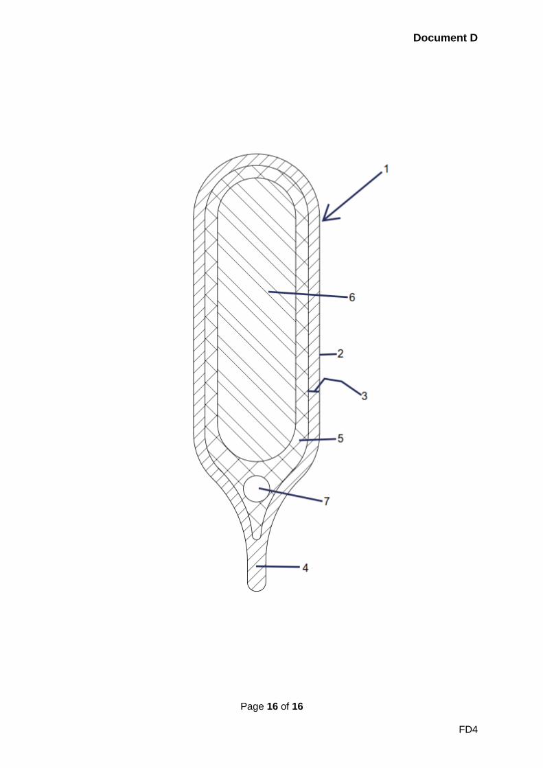
The drawing shows a release or sprinkler initiating member 1 which consists 5 of a small closed glass vessel 2 having a certain wall thickness 3. A
liquid displacement member 6 is arranged within the glass vessel 2, which
member 6 consists of a material having a heat-absorption capacity which is
smaller than the heat-absorption capacity of a liquid 5 also in the vessel
2. The displacement member 6 can, for example, consist of a synthetic 10 plastics material such as polytetrafluoroethylene (sold as Teflon(RTM)).
The displacement member 6 floats freely inside the vessel 2 in the liquid
5. After introducing the liquid 5 and fitting the displacement member 6, an
end 4 of the vessel 2 is sealed, thereby trapping the usual air bubble
indicated at 7. 15
The ratio between the volume of the liquid 5 and the volume of the liquid
displacement member 6 can be 1:1 to 1:5 and is preferably 1:3 whereas
(although not shown) the air bubble 7 occupies the same volume as the
liquid 5. 20
With this construction, the volume of the liquid 5 is substantially reduced
as compared with the prior art, with unchanged mechanical strength of the
small glass vessel 2. The smaller quantity of liquid is therefore more
quickly able to assume the temperature which is necessary for the bursting 25 of the glass vessel 2. Consequently, in the event of a fire, a sprinkler
incorporating a release or initiating member 1 constructed according to the
invention is opened more quickly than the known sprinklers without
displacement members, as quick as 10 seconds at 70 °C.
30 The glass vessels 2 will be used with sprinkler head systems as disclosed
above.
[CLAIMS OMITTED]
Document D
Page 16 of 16
FD4