Embed Size (px)
DESCRIPTION
FT3813, FT4015 Service manual
Citation preview
7/18/2019 A219 245 B019 4015 3813 Service
http://slidepdf.com/reader/full/a219-245-b019-4015-3813-service 1/372
A219/A245/B019
SERVICE MANUAL000917MIU
RICOH GROUP COMPANIES

7/18/2019 A219 245 B019 4015 3813 Service
http://slidepdf.com/reader/full/a219-245-b019-4015-3813-service 2/372

7/18/2019 A219 245 B019 4015 3813 Service
http://slidepdf.com/reader/full/a219-245-b019-4015-3813-service 3/372
A 2 1 9 / A 2 4 5
/ B 0 1 9
S E R V I C E MA N U A L
RICOH GROUP COMPANIES

7/18/2019 A219 245 B019 4015 3813 Service
http://slidepdf.com/reader/full/a219-245-b019-4015-3813-service 4/372
7/18/2019 A219 245 B019 4015 3813 Service
http://slidepdf.com/reader/full/a219-245-b019-4015-3813-service 5/372
A219/A245/B019
SERVICE MANUAL
000917MIU

7/18/2019 A219 245 B019 4015 3813 Service
http://slidepdf.com/reader/full/a219-245-b019-4015-3813-service 6/372

7/18/2019 A219 245 B019 4015 3813 Service
http://slidepdf.com/reader/full/a219-245-b019-4015-3813-service 7/372
It is the reader's responsibility when discussing the information contained within thisdocument to maintain a level of confidentiality that is in the best interest of RicohCorporation and its member companies.
NO PART OF THIS DOCUMENT MAY BE REPRODUCED IN ANY
FASHION AND DISTRIBUTED WITHOUT THE PRIOR
PERMISSION OF RICOH CORPORATION.
All product names, domain names or product illustrations, including desktop images,used in this document are trademarks, registered trademarks or the property of theirrespective companies.
They are used throughout this book in an informational or editorial fashion only and forthe benefit of such companies. No such use, or the use of any trade name, or website is intended to convey endorsement or other affiliation with Ricoh products.
2000 RICOH Corporation. All rights reserved.

7/18/2019 A219 245 B019 4015 3813 Service
http://slidepdf.com/reader/full/a219-245-b019-4015-3813-service 8/372

7/18/2019 A219 245 B019 4015 3813 Service
http://slidepdf.com/reader/full/a219-245-b019-4015-3813-service 9/372
The Service Manual contains information regarding service techniques, procedures,processes and spare parts of office equipment distributed by Ricoh Corporation. Users of this
manual should be either service trained or certified by successfully completing a Ricoh Technical Training Program.
Untrained and uncertified users utilizing information contained in this service manual to repair or modify Ricoh equipment risk personal injury, damage to property or loss of warranty protection.
Ricoh Corporation
WARNING

7/18/2019 A219 245 B019 4015 3813 Service
http://slidepdf.com/reader/full/a219-245-b019-4015-3813-service 10/372

7/18/2019 A219 245 B019 4015 3813 Service
http://slidepdf.com/reader/full/a219-245-b019-4015-3813-service 11/372
LEGEND
PRODUCT CODE COMPANY
GESTETNER RICOH SAVIN
A219 2715X FT4015 9115
A245 2718 FT4018 ---
B019 2913Z FT3813 2013Z
DOCUMENTATION HISTORY
REV. NO. DATE COMMENTS
* 3/97 Original Printing
2 7/98 Reprint
3 2/99 A245 Addition
4 3/2000 B019 Addition

7/18/2019 A219 245 B019 4015 3813 Service
http://slidepdf.com/reader/full/a219-245-b019-4015-3813-service 12/372
7/18/2019 A219 245 B019 4015 3813 Service
http://slidepdf.com/reader/full/a219-245-b019-4015-3813-service 13/372
Table of Contents
OVERALL MACHINE INFORMATION
1. SPECIFICATIONS . . . . . . . . . . . . . . . . . . . . . . . . . . . . . . . . . . . . . . 1-1
2. COPY PROCESS AROUND THE DRUM. . . . . . . . . . . . . . . . . . . . . 1-4
3. MECHANICAL COMPONENT LAYOUT . . . . . . . . . . . . . . . . . . . . . 1-6
4. DRIVE LAYOUT . . . . . . . . . . . . . . . . . . . . . . . . . . . . . . . . . . . . . . . . 1-7
5. PAPER PATH . . . . . . . . . . . . . . . . . . . . . . . . . . . . . . . . . . . . . . . . . . 1-8
6. ELECTRICAL COMPONENT DESCRIPTIONS. . . . . . . . . . . . . . . . 1-9
DETAILED DESCRIPTIONS
1. DRUM . . . . . . . . . . . . . . . . . . . . . . . . . . . . . . . . . . . . . . . . . . . . . . . . 2-1
1.1 OPC DRUM CHARACTERISTICS . . . . . . . . . . . . . . . . . . . . . . . . . . . . . . . . . . 2-1
1.2 DRIVE MECHANISM . . . . . . . . . . . . . . . . . . . . . . . . . . . . . . . . . . . . . . . . . . . . 2-2
2. CHARGE. . . . . . . . . . . . . . . . . . . . . . . . . . . . . . . . . . . . . . . . . . . . . . 2-3
2.1 OVERVIEW. . . . . . . . . . . . . . . . . . . . . . . . . . . . . . . . . . . . . . . . . . . . . . . . . . . . 2-3
2.2 CHARGE CORONA WIRE CLEANER MECHANISM . . . . . . . . . . . . . . . . . . . 2-4
2.3 CHARGE CORONA CIRCUIT . . . . . . . . . . . . . . . . . . . . . . . . . . . . . . . . . . . . . 2-5
3. OPTICS . . . . . . . . . . . . . . . . . . . . . . . . . . . . . . . . . . . . . . . . . . . . . . . 2-6
3.1 OVERVIEW. . . . . . . . . . . . . . . . . . . . . . . . . . . . . . . . . . . . . . . . . . . . . . . . . . . . 2-6
3.2 SCANNER DRIVE . . . . . . . . . . . . . . . . . . . . . . . . . . . . . . . . . . . . . . . . . . . . . . 2-7
3.3 LENS DRIVE. . . . . . . . . . . . . . . . . . . . . . . . . . . . . . . . . . . . . . . . . . . . . . . . . . . 2-8
3.4 4TH/5TH MIRROR DRIVE . . . . . . . . . . . . . . . . . . . . . . . . . . . . . . . . . . . . . . . . 2-9
3.5 AUTOMATIC IMAGE DENSITY SENSOR . . . . . . . . . . . . . . . . . . . . . . . . . . . 2-10
3.6 EXPOSURE LAMP VOLTAGE CONTROL . . . . . . . . . . . . . . . . . . . . . . . . . . 2-11
4. ERASE . . . . . . . . . . . . . . . . . . . . . . . . . . . . . . . . . . . . . . . . . . . . . . 2-15
4.1 OVERVIEW. . . . . . . . . . . . . . . . . . . . . . . . . . . . . . . . . . . . . . . . . . . . . . . . . . . 2-15
4.2 LEAD EDGE ERASE . . . . . . . . . . . . . . . . . . . . . . . . . . . . . . . . . . . . . . . . . . . 2-16
4.3 SIDE ERASE . . . . . . . . . . . . . . . . . . . . . . . . . . . . . . . . . . . . . . . . . . . . . . . . . 2-16
TOC i A219/A245/B019
7/18/2019 A219 245 B019 4015 3813 Service
http://slidepdf.com/reader/full/a219-245-b019-4015-3813-service 14/372
4.4 TRAILING EDGE ERASE. . . . . . . . . . . . . . . . . . . . . . . . . . . . . . . . . . . . . . . . 2-17
5. DEVELOPMENT . . . . . . . . . . . . . . . . . . . . . . . . . . . . . . . . . . . . . . . 2-18
5.1 OVERVIEW. . . . . . . . . . . . . . . . . . . . . . . . . . . . . . . . . . . . . . . . . . . . . . . . . . . 2-18
5.2 DRIVE MECHANISM . . . . . . . . . . . . . . . . . . . . . . . . . . . . . . . . . . . . . . . . . . . 2-19
5.3 CROSS-MIXING . . . . . . . . . . . . . . . . . . . . . . . . . . . . . . . . . . . . . . . . . . . . . . . 2-20
5.4 DEVELOPMENT BIAS FOR IMAGE DENSITY CONTROL . . . . . . . . . . . . . . 2-21
5.4.1 Base Bias Voltage Factor in Manual Image Density Mode . . . . . . . . . . . 2-22
5.4.2 Base Bias Voltage Factor in Automatic Image Density (ADS) Mode . . . 2-23
5.4.3 Drum Residual Voltage (VR) Correction Factor. . . . . . . . . . . . . . . . . . . . 2-23
5.5 DEVELOPMENT BIAS CIRCUIT . . . . . . . . . . . . . . . . . . . . . . . . . . . . . . . . . . 2-24
6. TONER SUPPLY . . . . . . . . . . . . . . . . . . . . . . . . . . . . . . . . . . . . . . 2-25
6.1 TONER BOTTLE REPLENISHMENT MECHANISM . . . . . . . . . . . . . . . . . . . 2-25
6.2 TONER SUPPLY MECHANISM . . . . . . . . . . . . . . . . . . . . . . . . . . . . . . . . . . . 2-26
6.3 TONER DENSITY DETECTION MECHANISM . . . . . . . . . . . . . . . . . . . . . . . 2-27
6.4 TD SENSOR CHECK AND TONER SUPPLY TIMING . . . . . . . . . . . . . . . . . 2-28
6.5 TONER SUPPLY CONTROL . . . . . . . . . . . . . . . . . . . . . . . . . . . . . . . . . . . . . 2-29
6.5.1 Modes Available . . . . . . . . . . . . . . . . . . . . . . . . . . . . . . . . . . . . . . . . . . . 2-29
6.5.2 Detect Supply Mode . . . . . . . . . . . . . . . . . . . . . . . . . . . . . . . . . . . . . . . . 2-29
6.5.3 Fixed Supply Mode . . . . . . . . . . . . . . . . . . . . . . . . . . . . . . . . . . . . . . . . . 2-32
6.5.4 Abnormal Condition in Toner Density Detection . . . . . . . . . . . . . . . . . . . 2-32
6.6 TONER END. . . . . . . . . . . . . . . . . . . . . . . . . . . . . . . . . . . . . . . . . . . . . . . . . . 2-33
6.6.1 Toner Near End. . . . . . . . . . . . . . . . . . . . . . . . . . . . . . . . . . . . . . . . . . . . 2-33
6.6.2 Toner End . . . . . . . . . . . . . . . . . . . . . . . . . . . . . . . . . . . . . . . . . . . . . . . 2-33
6.6.3 Toner End Recovery . . . . . . . . . . . . . . . . . . . . . . . . . . . . . . . . . . . . . . . . 2-34
7. IMAGE TRANSFER AND PAPER SEPARATION. . . . . . . . . . . . . 2-35
7.1 OVERALL . . . . . . . . . . . . . . . . . . . . . . . . . . . . . . . . . . . . . . . . . . . . . . . . . . . . 2-35
7.2 TRANSFER CORONA AND DISCHARGE PLATE CIRCUIT. . . . . . . . . . . . . 2-36
8. DRUM CLEANING . . . . . . . . . . . . . . . . . . . . . . . . . . . . . . . . . . . . . 2-37
8.1 OVERVIEW. . . . . . . . . . . . . . . . . . . . . . . . . . . . . . . . . . . . . . . . . . . . . . . . . . . 2-37
8.2 TONER RECYCLING MECHANISM . . . . . . . . . . . . . . . . . . . . . . . . . . . . . . . 2-38
9. QUENCHING. . . . . . . . . . . . . . . . . . . . . . . . . . . . . . . . . . . . . . . . . . 2-39
A219/A245/B019 ii TOC
7/18/2019 A219 245 B019 4015 3813 Service
http://slidepdf.com/reader/full/a219-245-b019-4015-3813-service 15/372
10. PAPER FEED AND REGISTRATION . . . . . . . . . . . . . . . . . . . . . 2-40
10.1 OVERVIEW. . . . . . . . . . . . . . . . . . . . . . . . . . . . . . . . . . . . . . . . . . . . . . . . . . 2-40
10.2 PAPER TRAY FEED. . . . . . . . . . . . . . . . . . . . . . . . . . . . . . . . . . . . . . . . . . . 2-41
10.2.1 Paper Lift Mechanism . . . . . . . . . . . . . . . . . . . . . . . . . . . . . . . . . . . . . . 2-41
10.2.2 Paper Feed Mechanism . . . . . . . . . . . . . . . . . . . . . . . . . . . . . . . . . . . . 2-42
10.3 BY-PASS FEED . . . . . . . . . . . . . . . . . . . . . . . . . . . . . . . . . . . . . . . . . . . . . . 2-43
10.3.1 Overview . . . . . . . . . . . . . . . . . . . . . . . . . . . . . . . . . . . . . . . . . . . . . . . . 2-43
10.3.2 Paper Feed Mechanism and Paper End Detection. . . . . . . . . . . . . . . . 2-44
10.4 PAPER REGISTRATION . . . . . . . . . . . . . . . . . . . . . . . . . . . . . . . . . . . . . . . 2-45
10.5 SIDE FENCE DOUBLE STOPPER MECHANISM . . . . . . . . . . . . . . . . . . . . 2-46
10.6 PAPER END DETECTION . . . . . . . . . . . . . . . . . . . . . . . . . . . . . . . . . . . . . . 2-47
10.7 PAPER FEED AND MISFEED DETECTION TIMING . . . . . . . . . . . . . . . . . 2-48
10.8 OTHERS. . . . . . . . . . . . . . . . . . . . . . . . . . . . . . . . . . . . . . . . . . . . . . . . . . . . 2-49
10.8.1 Paper Size Detection . . . . . . . . . . . . . . . . . . . . . . . . . . . . . . . . . . . . . . 2-49
10.8.2 Shock Absorber. . . . . . . . . . . . . . . . . . . . . . . . . . . . . . . . . . . . . . . . . . . 2-49
11. IMAGE FUSING . . . . . . . . . . . . . . . . . . . . . . . . . . . . . . . . . . . . . . 2-50
11.1 OVERVIEW. . . . . . . . . . . . . . . . . . . . . . . . . . . . . . . . . . . . . . . . . . . . . . . . . . 2-50
11.2 FUSING DRIVE MECHANISM . . . . . . . . . . . . . . . . . . . . . . . . . . . . . . . . . . . 2-51
11.3 FUSING LAMP CONTROL. . . . . . . . . . . . . . . . . . . . . . . . . . . . . . . . . . . . . . 2-52
11.4 FUSING LAMP CONTROL CIRCUIT . . . . . . . . . . . . . . . . . . . . . . . . . . . . . . 2-54
11.4.1 Overview . . . . . . . . . . . . . . . . . . . . . . . . . . . . . . . . . . . . . . . . . . . . . . . . 2-54
11.4.2 On/Off Control . . . . . . . . . . . . . . . . . . . . . . . . . . . . . . . . . . . . . . . . . . . . 2-55
11.4.3 Phase Control Mode . . . . . . . . . . . . . . . . . . . . . . . . . . . . . . . . . . . . . . . 2-55
11.4.4 Overheat Protection . . . . . . . . . . . . . . . . . . . . . . . . . . . . . . . . . . . . . . . 2-56
3. INSTALLATION
1. INSTALLATION REQUIREMENTS . . . . . . . . . . . . . . . . . . . . . . . . . 3-1
1.1 ENVIRONMENT . . . . . . . . . . . . . . . . . . . . . . . . . . . . . . . . . . . . . . . . . . . . . . . . 3-1
1.2 MACHINE LEVEL. . . . . . . . . . . . . . . . . . . . . . . . . . . . . . . . . . . . . . . . . . . . . . . 3-1
1.3 MINIMUM SPACE REQUIREMENTS . . . . . . . . . . . . . . . . . . . . . . . . . . . . . . . 3-2
1.4 POWER REQUIREMENTS . . . . . . . . . . . . . . . . . . . . . . . . . . . . . . . . . . . . . . . 3-2
TOC iii A219/A245/B019
7/18/2019 A219 245 B019 4015 3813 Service
http://slidepdf.com/reader/full/a219-245-b019-4015-3813-service 16/372
2. COPIER (A219). . . . . . . . . . . . . . . . . . . . . . . . . . . . . . . . . . . . . . . . . 3-3
2.1 ACCESSORY CHECK . . . . . . . . . . . . . . . . . . . . . . . . . . . . . . . . . . . . . . . . . . . 3-3
2.2 INSTALLATION PROCEDURE . . . . . . . . . . . . . . . . . . . . . . . . . . . . . . . . . . . . 3-4
3. DOCUMENT FEEDER (A662) . . . . . . . . . . . . . . . . . . . . . . . . . . . . . 3-8
3.1 ACCESSORY CHECK . . . . . . . . . . . . . . . . . . . . . . . . . . . . . . . . . . . . . . . . . . . 3-8
3.2 INSTALLATION PROCEDURE . . . . . . . . . . . . . . . . . . . . . . . . . . . . . . . . . . . . 3-9
4. SORTER (A657) . . . . . . . . . . . . . . . . . . . . . . . . . . . . . . . . . . . . . . . 3-12
4.1 ACCESSORY CHECK . . . . . . . . . . . . . . . . . . . . . . . . . . . . . . . . . . . . . . . . . . 3-12
4.2 INSTALLATION PROCEDURE . . . . . . . . . . . . . . . . . . . . . . . . . . . . . . . . . . . 3-13
5. OTHERS . . . . . . . . . . . . . . . . . . . . . . . . . . . . . . . . . . . . . . . . . . . . . 3-16
5.1 OPTICS ANTI-CONDENSATION HEATER INSTALLATION (OPTION) . . . . 3-16
5.2 TRAY HEATER INSTALLATION (OPTION). . . . . . . . . . . . . . . . . . . . . . . . . . 3-18
SERVICE TABLES
1. SERVICE REMARKS . . . . . . . . . . . . . . . . . . . . . . . . . . . . . . . . . . . . 4-1
1.1 GENERAL CAUTIONS . . . . . . . . . . . . . . . . . . . . . . . . . . . . . . . . . . . . . . . . . . . 4-1
1.2 IMAGING UNIT. . . . . . . . . . . . . . . . . . . . . . . . . . . . . . . . . . . . . . . . . . . . . . . . . 4-1
1.3 OPTICS. . . . . . . . . . . . . . . . . . . . . . . . . . . . . . . . . . . . . . . . . . . . . . . . . . . . . . . 4-2
1.4 TRANSFER CORONA . . . . . . . . . . . . . . . . . . . . . . . . . . . . . . . . . . . . . . . . . . . 4-3
1.5 FUSING UNIT. . . . . . . . . . . . . . . . . . . . . . . . . . . . . . . . . . . . . . . . . . . . . . . . . . 4-3
1.6 PAPER FEED . . . . . . . . . . . . . . . . . . . . . . . . . . . . . . . . . . . . . . . . . . . . . . . . . . 4-4
1.7 OTHERS. . . . . . . . . . . . . . . . . . . . . . . . . . . . . . . . . . . . . . . . . . . . . . . . . . . . . . 4-4
2. PROGRAM MODES . . . . . . . . . . . . . . . . . . . . . . . . . . . . . . . . . . . . . 4-6
2.1 BASIC OPERATION. . . . . . . . . . . . . . . . . . . . . . . . . . . . . . . . . . . . . . . . . . . . . 4-6
2.2 SP MODE . . . . . . . . . . . . . . . . . . . . . . . . . . . . . . . . . . . . . . . . . . . . . . . . . . . . . 4-7
2.3 SP MODE QUICK REFERENCE TABLE . . . . . . . . . . . . . . . . . . . . . . . . . . . . . 4-8
2.4 UP MODE AND SP MODE CROSS REFERENCE TABLE . . . . . . . . . . . . . . . 4-9
2.5 SERVICE PROGRAM MODE TABLE . . . . . . . . . . . . . . . . . . . . . . . . . . . . . . 4-10
2.6 CLEAR ALL MEMORY PROCEDURE . . . . . . . . . . . . . . . . . . . . . . . . . . . . . . 4-24
3. PRACTICAL SP MODE USE TABLE . . . . . . . . . . . . . . . . . . . . . . 4-26
A219/A245/B019 iv TOC
7/18/2019 A219 245 B019 4015 3813 Service
http://slidepdf.com/reader/full/a219-245-b019-4015-3813-service 17/372
4. SERVICE TABLES . . . . . . . . . . . . . . . . . . . . . . . . . . . . . . . . . . . . . 4-27
4.1 TEST POINTS (Main Control Board) . . . . . . . . . . . . . . . . . . . . . . . . . . . . . . . 4-27
4.2 VARIABLE RESISTORS. . . . . . . . . . . . . . . . . . . . . . . . . . . . . . . . . . . . . . . . . 4-27
PREVENTIVE MAINTENANCE
1. PREVENTIVE MAINTENANCE SCHEDULE. . . . . . . . . . . . . . . . . . 5-1
1.1 PM TABLE . . . . . . . . . . . . . . . . . . . . . . . . . . . . . . . . . . . . . . . . . . . . . . . . . . . . 5-1
1.2 REGULAR PM PROCEDURE . . . . . . . . . . . . . . . . . . . . . . . . . . . . . . . . . . . . . 5-4
2. SPECIAL TOOLS AND LUBRICANTS . . . . . . . . . . . . . . . . . . . . . . 5-7
REPLACEMENT AND ADJUSTMENT
1. EXTERIOR AND INNER COVERS. . . . . . . . . . . . . . . . . . . . . . . . . . 6-1
1.1 EXTERIOR COVER REMOVAL . . . . . . . . . . . . . . . . . . . . . . . . . . . . . . . . . . . . 6-1
1.1.1 Front Cover . . . . . . . . . . . . . . . . . . . . . . . . . . . . . . . . . . . . . . . . . . . . . . . . 6-1
1.1.2 Front Right Cover . . . . . . . . . . . . . . . . . . . . . . . . . . . . . . . . . . . . . . . . . . . 6-1
1.1.3 Rear Right Cover . . . . . . . . . . . . . . . . . . . . . . . . . . . . . . . . . . . . . . . . . . . 6-1
1.1.4 Lower Right Cover . . . . . . . . . . . . . . . . . . . . . . . . . . . . . . . . . . . . . . . . . . 6-2
1.1.5 Lower Left Cover. . . . . . . . . . . . . . . . . . . . . . . . . . . . . . . . . . . . . . . . . . . . 6-2
1.1.6 Upper Left Cover. . . . . . . . . . . . . . . . . . . . . . . . . . . . . . . . . . . . . . . . . . . . 6-2
1.1.7 Rear Cover . . . . . . . . . . . . . . . . . . . . . . . . . . . . . . . . . . . . . . . . . . . . . . . . 6-2
1.1.8 Upper Cover . . . . . . . . . . . . . . . . . . . . . . . . . . . . . . . . . . . . . . . . . . . . . . . 6-3
1.2 INNER COVER REMOVAL . . . . . . . . . . . . . . . . . . . . . . . . . . . . . . . . . . . . . . . 6-4
2. OPTICS . . . . . . . . . . . . . . . . . . . . . . . . . . . . . . . . . . . . . . . . . . . . . . . 6-5
2.1 EXPOSURE GLASS REMOVAL . . . . . . . . . . . . . . . . . . . . . . . . . . . . . . . . . . . 6-5
2.2 1ST SCANNER/EXPOSURE LAMP REMOVAL . . . . . . . . . . . . . . . . . . . . . . . 6-6
2.3 SCANNER BELT REMOVAL . . . . . . . . . . . . . . . . . . . . . . . . . . . . . . . . . . . . . . 6-8
2.4 1ST AND 2ND SCANNER POSITION ADJUSTMENT . . . . . . . . . . . . . . . . . . 6-9
2.5 SCANNER DRIVE MOTOR REMOVAL . . . . . . . . . . . . . . . . . . . . . . . . . . . . . 6-10
2.6 LENS DRIVE MOTOR REMOVAL . . . . . . . . . . . . . . . . . . . . . . . . . . . . . . . . . 6-11
2.7 4TH/5TH MIRROR DRIVE MOTOR REMOVAL. . . . . . . . . . . . . . . . . . . . . . . 6-12
TOC v A219/A245/B019
7/18/2019 A219 245 B019 4015 3813 Service
http://slidepdf.com/reader/full/a219-245-b019-4015-3813-service 18/372
2.8 2ND MIRROR REPLACEMENT . . . . . . . . . . . . . . . . . . . . . . . . . . . . . . . . . . . 6-13
2.9 3RD MIRROR REPLACEMENT . . . . . . . . . . . . . . . . . . . . . . . . . . . . . . . . . . . 6-14
2.10 4TH AND 5TH MIRROR REPLACEMENT. . . . . . . . . . . . . . . . . . . . . . . . . . 6-15
2.11 ADS SENSOR REPLACEMENT . . . . . . . . . . . . . . . . . . . . . . . . . . . . . . . . . 6-17
3. AROUND THE DRUM. . . . . . . . . . . . . . . . . . . . . . . . . . . . . . . . . . . 6-18
3.1 IMAGING UNIT REMOVAL AND TONER BOTTLE REMOVAL . . . . . . . . . . 6-18
3.2 CHARGE CORONA WIRE AND CHARGE CORONA GRID REPLACEMENT. . . . . . . . . . . . . . . . . . . . . . . . . . . . . . . . . . . . . . . . . . . . . . . 6-19
3.3 CLEANING BLADE REPLACEMENT. . . . . . . . . . . . . . . . . . . . . . . . . . . . . . . 6-20
3.4 DRUM REPLACEMENT . . . . . . . . . . . . . . . . . . . . . . . . . . . . . . . . . . . . . . . . . 6-21
3.5 TONER COLLECTION COIL AND TONER RECYCLING BELT
REPLACEMENT. . . . . . . . . . . . . . . . . . . . . . . . . . . . . . . . . . . . . . . . . . . . . . . 6-22
3.6 DEVELOPER REPLACEMENT . . . . . . . . . . . . . . . . . . . . . . . . . . . . . . . . . . . 6-23
3.7 REPLACEMENT THE TONER DENSITY SENSOR (TD SENSOR) . . . . . . . 6-24
3.8 AGITATOR REPLACEMENT . . . . . . . . . . . . . . . . . . . . . . . . . . . . . . . . . . . . . 6-25
3.9 TONER SUPPLY MOTOR ASS’Y REPLACEMENT . . . . . . . . . . . . . . . . . . . 6-26
3.10 ERASE LAMP REPLACEMENT. . . . . . . . . . . . . . . . . . . . . . . . . . . . . . . . . . 6-27
3.11 QUENCHING LAMP REPLACEMENT . . . . . . . . . . . . . . . . . . . . . . . . . . . . . 6-28
4. PAPER FEED . . . . . . . . . . . . . . . . . . . . . . . . . . . . . . . . . . . . . . . . . 6-29
4.1 PAPER TRAY REMOVAL. . . . . . . . . . . . . . . . . . . . . . . . . . . . . . . . . . . . . . . . 6-29
4.2 TRAY FEED ROLLER REPLACEMENT . . . . . . . . . . . . . . . . . . . . . . . . . . . . 6-30
4.3 TRAY PAPER FEED ROLLER ADJUSTMENT . . . . . . . . . . . . . . . . . . . . . . . 6-31
4.4 BY-PASS FEED ROLLER AND FRICTION PAD REPLACEMENT. . . . . . . . 6-32
4.5 BY-PASS PAPER FEED CLUTCH, HIGH VOLTAGE SUPPLY BOARD, AND REGISTRATION CLUTCH REPLACEMENT. . . . . . . . . . . . . . . . . . . . . 6-34
4.6 RIGHT VERTICAL GUIDE SWITCH REPLACEMENT . . . . . . . . . . . . . . . . . 6-35
4.7 RELAY ROLLER CLUTCH AND PAPER FEED CLUTCH REPLACEMENT. . . . . . . . . . . . . . . . . . . . . . . . . . . . . . . . . . . . . . . . . . . . . . . 6-36
4.8 PAPER SIZE SWITCH REPLACEMENT . . . . . . . . . . . . . . . . . . . . . . . . . . . . 6-37
4.9 BY-PASS PAPER END SENSOR AND REGISTRATION SENSOR REPLACEMENT. . . . . . . . . . . . . . . . . . . . . . . . . . . . . . . . . . . . . . . . . . . . . . . 6-38
5. FUSING. . . . . . . . . . . . . . . . . . . . . . . . . . . . . . . . . . . . . . . . . . . . . . 6-39
5.1 FUSING UNIT REMOVAL . . . . . . . . . . . . . . . . . . . . . . . . . . . . . . . . . . . . . . . 6-39
5.2 HOT ROLLER REPLACEMENT. . . . . . . . . . . . . . . . . . . . . . . . . . . . . . . . . . . 6-40
A219/A245/B019 vi TOC
7/18/2019 A219 245 B019 4015 3813 Service
http://slidepdf.com/reader/full/a219-245-b019-4015-3813-service 19/372
5.3 PRESSURE ROLLER REPLACEMENT. . . . . . . . . . . . . . . . . . . . . . . . . . . . . 6-41
5.4 HOT ROLLER STRIPPER REPLACEMENT . . . . . . . . . . . . . . . . . . . . . . . . . 6-42
5.5 FUSING ENTRANCE GUIDE ADJUSTMENT . . . . . . . . . . . . . . . . . . . . . . . . 6-43
5.6 FUSING PRESSURE ADJUSTMENT . . . . . . . . . . . . . . . . . . . . . . . . . . . . . . 6-44
6. TRANSFER/SEPARATION . . . . . . . . . . . . . . . . . . . . . . . . . . . . . . 6-45
6.1 TRANSFER CORONA WIRE REPLACEMENT . . . . . . . . . . . . . . . . . . . . . . . 6-45
6.2 DISCHARGE PLATE REPLACEMENT . . . . . . . . . . . . . . . . . . . . . . . . . . . . . 6-46
7. OTHERS . . . . . . . . . . . . . . . . . . . . . . . . . . . . . . . . . . . . . . . . . . . . . 6-47
7.1 OZONE FILTER REPLACEMENT . . . . . . . . . . . . . . . . . . . . . . . . . . . . . . . . . 6-47
7.2 MAIN CONTROL BOARD REPLACEMENT . . . . . . . . . . . . . . . . . . . . . . . . . 6-48
8. COPY QUALITY ADJUSTMENT . . . . . . . . . . . . . . . . . . . . . . . . . . 6-49
8.1 LIGHT INTENSITY ADJUSTMENT . . . . . . . . . . . . . . . . . . . . . . . . . . . . . . . . 6-50
8.1.1 Base Exposure Lamp Voltage Adjustment . . . . . . . . . . . . . . . . . . . . . . . 6-50
8.1.2 Image Density Adjustment . . . . . . . . . . . . . . . . . . . . . . . . . . . . . . . . . . . 6-51
8.2 DEVELOPMENT BIAS VOLTAGE ADJUSTMENT . . . . . . . . . . . . . . . . . . . . 6-52
8.2.1 Base Bias Voltage Adjustment . . . . . . . . . . . . . . . . . . . . . . . . . . . . . . . . 6-52
8.2.2 SP Bias Settings . . . . . . . . . . . . . . . . . . . . . . . . . . . . . . . . . . . . . . . . . . . 6-53
8.3 TONER DENSITY ADJUSTMENT . . . . . . . . . . . . . . . . . . . . . . . . . . . . . . . . . 6-54
8.4 TONER SUPPLY RATIO SELECTION. . . . . . . . . . . . . . . . . . . . . . . . . . . . . . 6-54
8.5 GRID VOLTAGE ADJUSTMENT . . . . . . . . . . . . . . . . . . . . . . . . . . . . . . . . . . 6-55
8.6 TRANSFER CURRENT ADJUSTMENT. . . . . . . . . . . . . . . . . . . . . . . . . . . . . 6-56
8.7 CHARGE CURRENT ADJUSTMENT. . . . . . . . . . . . . . . . . . . . . . . . . . . . . . . 6-57
8.8 HORIZONTAL MAGNIFICATION ADJUSTMENT . . . . . . . . . . . . . . . . . . . . . 6-58
8.9 VERTICAL MAGNIFICATION ADJUSTMENT . . . . . . . . . . . . . . . . . . . . . . . . 6-58
8.10 FOCUS ADJUSTMENT . . . . . . . . . . . . . . . . . . . . . . . . . . . . . . . . . . . . . . . . 6-59
8.11 LEADING EDGE ERASE MARGIN ADJUSTMENT. . . . . . . . . . . . . . . . . . . 6-59
8.12 REGISTRATION ADJUSTMENT . . . . . . . . . . . . . . . . . . . . . . . . . . . . . . . . . 6-59
8.13 4TH/5TH MIRROR HEIGHT ADJUSTMENT . . . . . . . . . . . . . . . . . . . . . . . . 6-60
8.14 ADS (Auto Image Density Sensor) ADJUSTMENT . . . . . . . . . . . . . . . . . . . 6-61
8.15 SIDE-TO -SIDE REGISTRATION ADJUSTMENT . . . . . . . . . . . . . . . . . . . . 6-62
TOC vii A219/A245/B019
7/18/2019 A219 245 B019 4015 3813 Service
http://slidepdf.com/reader/full/a219-245-b019-4015-3813-service 20/372
TROUBLESHOOTING
1. COPY QUALITY . . . . . . . . . . . . . . . . . . . . . . . . . . . . . . . . . . . . . . . . 7-1
1.1 BLANK COPY (WHITE COPY). . . . . . . . . . . . . . . . . . . . . . . . . . . . . . . . . . . . . 7-1
1.2 DIRTY BACKGROUND . . . . . . . . . . . . . . . . . . . . . . . . . . . . . . . . . . . . . . . . . . 7-3
1.3 UNEVEN IMAGE DENSITY . . . . . . . . . . . . . . . . . . . . . . . . . . . . . . . . . . . . . . . 7-5
1.4 VERTICAL BLACK BANDS . . . . . . . . . . . . . . . . . . . . . . . . . . . . . . . . . . . . . . . 7-6
1.5 VERTICAL BLACK LINES . . . . . . . . . . . . . . . . . . . . . . . . . . . . . . . . . . . . . . . . 7-7
1.6 VERTICAL WHITE LINES OR BANDS-1 (DULL OR BLURRED) . . . . . . . . . . 7-8
1.7 VERTICAL WHITE LINES OR BANDS-2 (THIN, DISTINCT). . . . . . . . . . . . . . 7-9
1.8 HORIZONTAL BLACK/WHITE LINES . . . . . . . . . . . . . . . . . . . . . . . . . . . . . . 7-10
1.9 JITTER . . . . . . . . . . . . . . . . . . . . . . . . . . . . . . . . . . . . . . . . . . . . . . . . . . . . . . 7-11
1.10 BLACK SPOTS ON THE COPY IMAGE . . . . . . . . . . . . . . . . . . . . . . . . . . . 7-12
1.11 SKEWED (OPTICAL) COPY IMAGE . . . . . . . . . . . . . . . . . . . . . . . . . . . . . . 7-13
1.12 TONER DENSITY ON COPIES TOO HIGH. . . . . . . . . . . . . . . . . . . . . . . . . 7-14
1.13 TONER DENSITY ON COPIES TOO LOW . . . . . . . . . . . . . . . . . . . . . . . . . 7-16
1.14 UNFUSED COPY IMAGE. . . . . . . . . . . . . . . . . . . . . . . . . . . . . . . . . . . . . . . 7-18
1.15 CREASING PAPER AFTER FUSING . . . . . . . . . . . . . . . . . . . . . . . . . . . . . 7-19
1.16 PAPER MISFEED. . . . . . . . . . . . . . . . . . . . . . . . . . . . . . . . . . . . . . . . . . . . . 7-20
1.17 ABNORMAL CONDITION IN TONER DENSITY DETECTION . . . . . . . . . . 7-21
2. SERVICE CALL CONDITIONS . . . . . . . . . . . . . . . . . . . . . . . . . . . 7-23
3. ELECTRICAL COMPONENT DEFECTS . . . . . . . . . . . . . . . . . . . . 7-29
3.1 SENSORS . . . . . . . . . . . . . . . . . . . . . . . . . . . . . . . . . . . . . . . . . . . . . . . . . . . 7-29
3.2 SWITCHES. . . . . . . . . . . . . . . . . . . . . . . . . . . . . . . . . . . . . . . . . . . . . . . . . . . 7-30
4. BLOWN FUSE CONDITIONS. . . . . . . . . . . . . . . . . . . . . . . . . . . . . 7-31
5. USER CODES. . . . . . . . . . . . . . . . . . . . . . . . . . . . . . . . . . . . . . . . . 7-31
A219/A245/B019 viii TOC
7/18/2019 A219 245 B019 4015 3813 Service
http://slidepdf.com/reader/full/a219-245-b019-4015-3813-service 21/372
DOCUMENT FEEDER A662
– DOCUMENT FEEDER (A662) –
1. SPECIFICATIONS . . . . . . . . . . . . . . . . . . . . . . . . . . . . . . . . . . . . . . 8-1
2. COMPONENT LAYOUT . . . . . . . . . . . . . . . . . . . . . . . . . . . . . . . . . . 8-2
2.1 MECHANICAL COMPONENTS . . . . . . . . . . . . . . . . . . . . . . . . . . . . . . . . . . . . 8-2
2.2 ELECTRICAL COMPONENTS. . . . . . . . . . . . . . . . . . . . . . . . . . . . . . . . . . . . . 8-2
3. ELECTRICAL COMPONENT DESCRIPTIONS. . . . . . . . . . . . . . . . 8-3
4. POWER DISTRIBUTION . . . . . . . . . . . . . . . . . . . . . . . . . . . . . . . . . 8-4
5. BASIC OPERATION. . . . . . . . . . . . . . . . . . . . . . . . . . . . . . . . . . . . . 8-5
6. INTERFACE CIRCUIT . . . . . . . . . . . . . . . . . . . . . . . . . . . . . . . . . . . 8-6
7. ORIGINAL FEED . . . . . . . . . . . . . . . . . . . . . . . . . . . . . . . . . . . . . . . 8-7
7.1 ORIGINAL PICK-UP MECHANISM . . . . . . . . . . . . . . . . . . . . . . . . . . . . . . . . . 8-7
7.2 ORIGINAL SEPARATION MECHANISM . . . . . . . . . . . . . . . . . . . . . . . . . . . . . 8-8
7.3 ORIGINAL FEED-IN MECHANISM . . . . . . . . . . . . . . . . . . . . . . . . . . . . . . . . . 8-9
7.4 ORIGINAL FEED-OUT MECHANISM . . . . . . . . . . . . . . . . . . . . . . . . . . . . . . 8-10
7.5 DF MOTOR CIRCUIT . . . . . . . . . . . . . . . . . . . . . . . . . . . . . . . . . . . . . . . . . . . 8-11
7.6 ORIGINAL FEED AND MISFEED DETECTION TIMING. . . . . . . . . . . . . . . . 8-12
8. SERVICE TABLES . . . . . . . . . . . . . . . . . . . . . . . . . . . . . . . . . . . . . 8-13
8.1 DIP SWITCHES . . . . . . . . . . . . . . . . . . . . . . . . . . . . . . . . . . . . . . . . . . . . . . . 8-13
8.2 VARIABLE RESISTORS. . . . . . . . . . . . . . . . . . . . . . . . . . . . . . . . . . . . . . . . . 8-13
8.3 FUSE . . . . . . . . . . . . . . . . . . . . . . . . . . . . . . . . . . . . . . . . . . . . . . . . . . . . . . . 8-13
9. REPLACEMENT AND ADJUSTMENT . . . . . . . . . . . . . . . . . . . . . 8-14
9.1 TRANSPORT BELT REPLACEMENT . . . . . . . . . . . . . . . . . . . . . . . . . . . . . . 8-14
9.2 FEED-IN UNIT REMOVAL . . . . . . . . . . . . . . . . . . . . . . . . . . . . . . . . . . . . . . . 8-16
9.3 PICK-UP ROLLER REPLACEMENT . . . . . . . . . . . . . . . . . . . . . . . . . . . . . . . 8-17
9.4 FEED ROLLER REPLACEMENT. . . . . . . . . . . . . . . . . . . . . . . . . . . . . . . . . . 8-18
9.5 FRICTION BELT REPLACEMENT. . . . . . . . . . . . . . . . . . . . . . . . . . . . . . . . . 8-19
9.6 PICK-UP SOLENOID ADJUSTMENT . . . . . . . . . . . . . . . . . . . . . . . . . . . . . . 8-20
TOC ix A219/A245/B019
7/18/2019 A219 245 B019 4015 3813 Service
http://slidepdf.com/reader/full/a219-245-b019-4015-3813-service 22/372
SORTER A657
1. SPECIFICATIONS . . . . . . . . . . . . . . . . . . . . . . . . . . . . . . . . . . . . . . 9-1
2. COMPONENT LAYOUT . . . . . . . . . . . . . . . . . . . . . . . . . . . . . . . . . . 9-2
3. ELECTRICAL COMPONENT DESCRIPTIONS. . . . . . . . . . . . . . . . 9-3
4. BASIC OPERATION. . . . . . . . . . . . . . . . . . . . . . . . . . . . . . . . . . . . . 9-4
5. EXIT ROLLER DRIVE MECHANISM . . . . . . . . . . . . . . . . . . . . . . . . 9-5
6. BIN DRIVE MECHANISM . . . . . . . . . . . . . . . . . . . . . . . . . . . . . . . . . 9-6
7. MISFEED DETECTION . . . . . . . . . . . . . . . . . . . . . . . . . . . . . . . . . . 9-8
8. SERVICE TABLES . . . . . . . . . . . . . . . . . . . . . . . . . . . . . . . . . . . . . . 9-88.1 FUSE . . . . . . . . . . . . . . . . . . . . . . . . . . . . . . . . . . . . . . . . . . . . . . . . . . . . . . . . 9-8
9. PREPARATION FOR TRANSPORTATION. . . . . . . . . . . . . . . . . . . 9-9
10. ROLLER DRIVE BELT REPLACEMENT. . . . . . . . . . . . . . . . . . . 9-10
11. BIN GUIDE LUBRICATION . . . . . . . . . . . . . . . . . . . . . . . . . . . . . 9-11
APPENDIX
ELECTRICAL COMPONENT LAYOUT (A219) (A662) (A657) . . . . . 10-1
COPIER TIMING CHART (A219) . . . . . . . . . . . . . . . . . . . . . . . . . . . . 10-6
A245 SERVICE MANUAL
1. SPECIFICATIONS . . . . . . . . . . . . . . . . . . . . . . . . . . . . . . . . . . . . . 11-1
2. MECHANICAL COMPONENT LAYOUT . . . . . . . . . . . . . . . . . . . . 11-4
3. DRIVE LAUOUT . . . . . . . . . . . . . . . . . . . . . . . . . . . . . . . . . . . . . . . 11-5
4. PAPER PATH . . . . . . . . . . . . . . . . . . . . . . . . . . . . . . . . . . . . . . . . . 11-6
5. ELECTRICAL COMPONENT DESCRIPTIONS. . . . . . . . . . . . . . . 11-7
6. PAPER FEED . . . . . . . . . . . . . . . . . . . . . . . . . . . . . . . . . . . . . . . . 11-10
6.1 OVERVIEW. . . . . . . . . . . . . . . . . . . . . . . . . . . . . . . . . . . . . . . . . . . . . . . . . . 11-10
6.2 PAPER LIFT MECHANISM . . . . . . . . . . . . . . . . . . . . . . . . . . . . . . . . . . . . . 11-11
A219/A245/B019 x TOC
7/18/2019 A219 245 B019 4015 3813 Service
http://slidepdf.com/reader/full/a219-245-b019-4015-3813-service 23/372
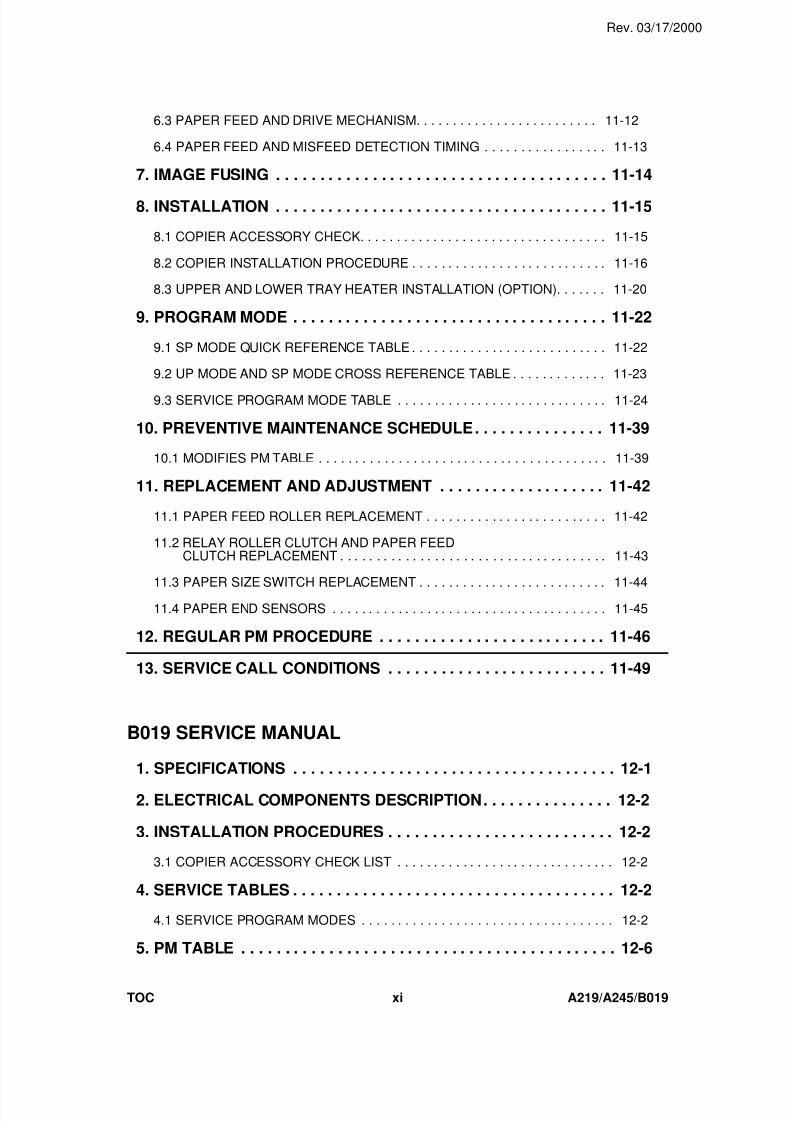
6.3 PAPER FEED AND DRIVE MECHANISM. . . . . . . . . . . . . . . . . . . . . . . . . 11-12
6.4 PAPER FEED AND MISFEED DETECTION TIMING . . . . . . . . . . . . . . . . . 11-13
7. IMAGE FUSING . . . . . . . . . . . . . . . . . . . . . . . . . . . . . . . . . . . . . . 11-14
8. INSTALLATION . . . . . . . . . . . . . . . . . . . . . . . . . . . . . . . . . . . . . . 11-15
8.1 COPIER ACCESSORY CHECK. . . . . . . . . . . . . . . . . . . . . . . . . . . . . . . . . . 11-15
8.2 COPIER INSTALLATION PROCEDURE . . . . . . . . . . . . . . . . . . . . . . . . . . . 11-16
8.3 UPPER AND LOWER TRAY HEATER INSTALLATION (OPTION). . . . . . . 11-20
9. PROGRAM MODE . . . . . . . . . . . . . . . . . . . . . . . . . . . . . . . . . . . . 11-22
9.1 SP MODE QUICK REFERENCE TABLE . . . . . . . . . . . . . . . . . . . . . . . . . . . 11-22
9.2 UP MODE AND SP MODE CROSS REFERENCE TABLE . . . . . . . . . . . . . 11-23
9.3 SERVICE PROGRAM MODE TABLE . . . . . . . . . . . . . . . . . . . . . . . . . . . . . 11-24
10. PREVENTIVE MAINTENANCE SCHEDULE. . . . . . . . . . . . . . . 11-39
10.1 MODIFIES PM TABLE . . . . . . . . . . . . . . . . . . . . . . . . . . . . . . . . . . . . . . . . 11-39
11. REPLACEMENT AND ADJUSTMENT . . . . . . . . . . . . . . . . . . . 11-42
11.1 PAPER FEED ROLLER REPLACEMENT . . . . . . . . . . . . . . . . . . . . . . . . . 11-42
11.2 RELAY ROLLER CLUTCH AND PAPER FEED CLUTCH REPLACEMENT . . . . . . . . . . . . . . . . . . . . . . . . . . . . . . . . . . . . . 11-43
11.3 PAPER SIZE SWITCH REPLACEMENT . . . . . . . . . . . . . . . . . . . . . . . . . . 11-44
11.4 PAPER END SENSORS . . . . . . . . . . . . . . . . . . . . . . . . . . . . . . . . . . . . . . 11-45
12. REGULAR PM PROCEDURE . . . . . . . . . . . . . . . . . . . . . . . . . . 11-46
13. SERVICE CALL CONDITIONS . . . . . . . . . . . . . . . . . . . . . . . . . 11-49
B019 SERVICE MANUAL
1. SPECIFICATIONS . . . . . . . . . . . . . . . . . . . . . . . . . . . . . . . . . . . . . 12-1
2. ELECTRICAL COMPONENTS DESCRIPTION. . . . . . . . . . . . . . . 12-2
3. INSTALLATION PROCEDURES . . . . . . . . . . . . . . . . . . . . . . . . . . 12-2
3.1 COPIER ACCESSORY CHECK LIST . . . . . . . . . . . . . . . . . . . . . . . . . . . . . . 12-2
4. SERVICE TABLES . . . . . . . . . . . . . . . . . . . . . . . . . . . . . . . . . . . . . 12-2
4.1 SERVICE PROGRAM MODES . . . . . . . . . . . . . . . . . . . . . . . . . . . . . . . . . . . 12-2
5. PM TABLE . . . . . . . . . . . . . . . . . . . . . . . . . . . . . . . . . . . . . . . . . . . 12-6
Rev. 03/17/2000
TOC xi A219/A245/B019
7/18/2019 A219 245 B019 4015 3813 Service
http://slidepdf.com/reader/full/a219-245-b019-4015-3813-service 24/372
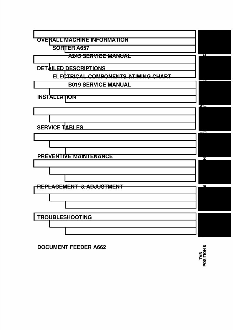
OVERALL MACHINE INFORMATION
SORTER A657
A245 SERVICE MANUAL
T A B
P
O S I T I O N
1
T A B
P O S I T I O N
2
T A B
P O S I T I O N
3
DETAILED DESCRIPTIONS
ELECTRICAL COMPONENTS &TIMING CHART
B019 SERVICE MANUAL
INSTALLATION
T A B
P O S I T I O N
4SERVICE TABLES
T A B
P O
S I T I O N
5
T A B
P O S I T I O N
6
T
A B
P O S I T I O N
7
T A B
P O S I T I O N
8
PREVENTIVE MAINTENANCE
REPLACEMENT & ADJUSTMENT
TROUBLESHOOTING
DOCUMENT FEEDER A662

7/18/2019 A219 245 B019 4015 3813 Service
http://slidepdf.com/reader/full/a219-245-b019-4015-3813-service 25/372
7/18/2019 A219 245 B019 4015 3813 Service
http://slidepdf.com/reader/full/a219-245-b019-4015-3813-service 26/372
A219
SERVICE MANUAL

7/18/2019 A219 245 B019 4015 3813 Service
http://slidepdf.com/reader/full/a219-245-b019-4015-3813-service 27/372

7/18/2019 A219 245 B019 4015 3813 Service
http://slidepdf.com/reader/full/a219-245-b019-4015-3813-service 28/372
OVERALL
MACHINE INFORMATION

7/18/2019 A219 245 B019 4015 3813 Service
http://slidepdf.com/reader/full/a219-245-b019-4015-3813-service 29/372
7/18/2019 A219 245 B019 4015 3813 Service
http://slidepdf.com/reader/full/a219-245-b019-4015-3813-service 30/372
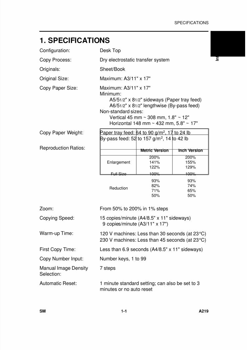
1. SPECIFICATIONS
Configuration: Desk Top
Copy Process: Dry electrostatic transfer systemOriginals: Sheet/Book
Original Size: Maximum: A3/11" x 17"
Copy Paper Size: Maximum: A3/11" x 17"Minimum:
A5/51/2" x 81/2" sideways (Paper tray feed)A6/51/2" x 81/2" lengthwise (By-pass feed)
Non-standard sizes:Vertical 45 mm ~ 308 mm, 1.8" ~ 12"Horizontal 148 mm ~ 432 mm, 5.8" ~ 17"
Copy Paper Weight: Paper tray feed: 64 to 90 g/m2, 17 to 24 lbBy-pass feed: 52 to 157 g/m2, 14 to 42 lb
Reproduction Ratios:
Zoom: From 50% to 200% in 1% steps
Copying Speed: 15 copies/minute (A4/8.5" x 11" sideways) 9 copies/minute (A3/11" x 17")
Warm-up Time: 120 V machines: Less than 30 seconds (at 23°C)230 V machines: Less than 45 seconds (at 23°C)
First Copy Time: Less than 6.9 seconds (A4/8.5" x 11" sideways)
Copy Number Input: Number keys, 1 to 99
Manual Image DensitySelection:
7 steps
Automatic Reset: 1 minute standard setting; can also be set to 3minutes or no auto reset
Metric Version Inch Version
Enlargement200%141%122%
200%155%129%
Full Size 100% 100%
Reduction 93% 82% 71% 50%
93% 74% 65% 50%
O v e r a l l
I
n f o r m a t i o n
SPECIFICATIONS
SM 1-1 A219
7/18/2019 A219 245 B019 4015 3813 Service
http://slidepdf.com/reader/full/a219-245-b019-4015-3813-service 31/372
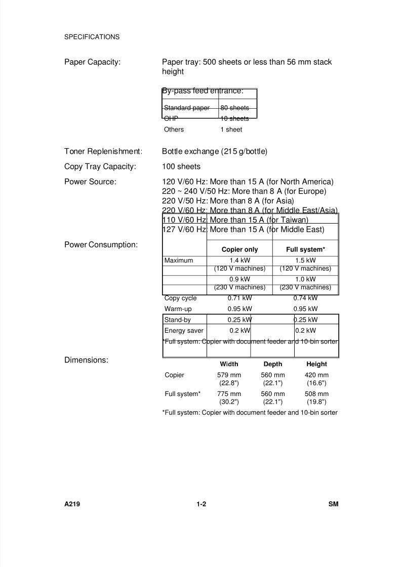
Paper Capacity: Paper tray: 500 sheets or less than 56 mm stackheight
By-pass feed entrance:
Toner Replenishment: Bottle exchange (215 g/bottle)
Copy Tray Capacity: 100 sheets
Power Source: 120 V/60 Hz: More than 15 A (for North America)220 ~ 240 V/50 Hz: More than 8 A (for Europe)220 V/50 Hz: More than 8 A (for Asia)220 V/60 Hz: More than 8 A (for Middle East/Asia)110 V/60 Hz: More than 15 A (for Taiwan)127 V/60 Hz: More than 15 A (for Middle East)
Power Consumption:
Dimensions:
Copier only Full system*
Maximum 1.4 kW(120 V machines)
1.5 kW(120 V machines)
0.9 kW(230 V machines)
1.0 kW(230 V machines)
Copy cycle 0.71 kW 0.74 kWWarm-up 0.95 kW 0.95 kW
Stand-by 0.25 kW 0.25 kW
Energy saver 0.2 kW 0.2 kW
*Full system: Copier with document feeder and 10-bin sorter
Width Depth Height
Copier 579 mm(22.8")
560 mm(22.1")
420 mm(16.6")
Full system* 775 mm(30.2") 560 mm(22.1") 508 mm(19.8")
*Full system: Copier with document feeder and 10-bin sorter
Standard paper 80 sheets
OHP 10 sheets
Others 1 sheet
SPECIFICATIONS
A219 1-2 SM
7/18/2019 A219 245 B019 4015 3813 Service
http://slidepdf.com/reader/full/a219-245-b019-4015-3813-service 32/372
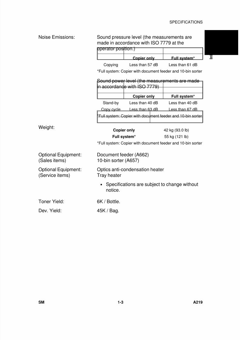
Noise Emissions: Sound pressure level (the measurements aremade in accordance with ISO 7779 at theoperator position.)
Sound power level (the measurements are madein accordance with ISO 7779)
Weight:
Optional Equipment:(Sales items)
Document feeder (A662)10-bin sorter (A657)
Optional Equipment:
(Service items)
Optics anti-condensation heater
Tray heater• Specifications are subject to change without
notice.
Toner Yield: 6K / Bottle.
Dev. Yield: 45K / Bag.
Copier only Full system*Copying Less than 57 dB Less than 61 dB
*Full system: Copier with document feeder and 10-bin sorter
Copier only Full system*
Stand-by Less than 40 dB Less than 40 dB
Copy cycle Less than 63 dB Less than 67 dB
*Full system: Copier with document feeder and 10-bin sorter
Copier only 42 kg (93.0 lb)
Full system* 55 kg (121 lb)
*Full system: Copier with document feeder and 10-bin sorter
O v e r a l l
I
n f o r m a t i o n
SPECIFICATIONS
SM 1-3 A219
7/18/2019 A219 245 B019 4015 3813 Service
http://slidepdf.com/reader/full/a219-245-b019-4015-3813-service 33/372
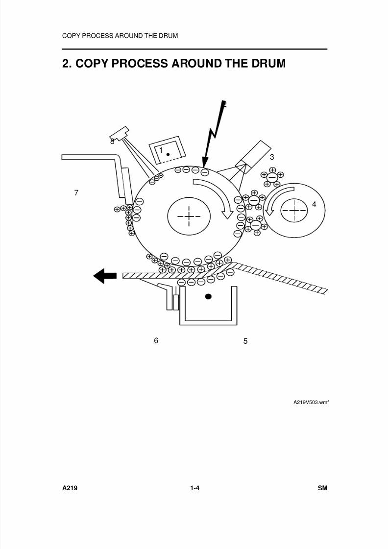
2. COPY PROCESS AROUND THE DRUM
2
6 5
47
81
3
A219V503.wmf
COPY PROCESS AROUND THE DRUM
A219 1-4 SM
7/18/2019 A219 245 B019 4015 3813 Service
http://slidepdf.com/reader/full/a219-245-b019-4015-3813-service 34/372
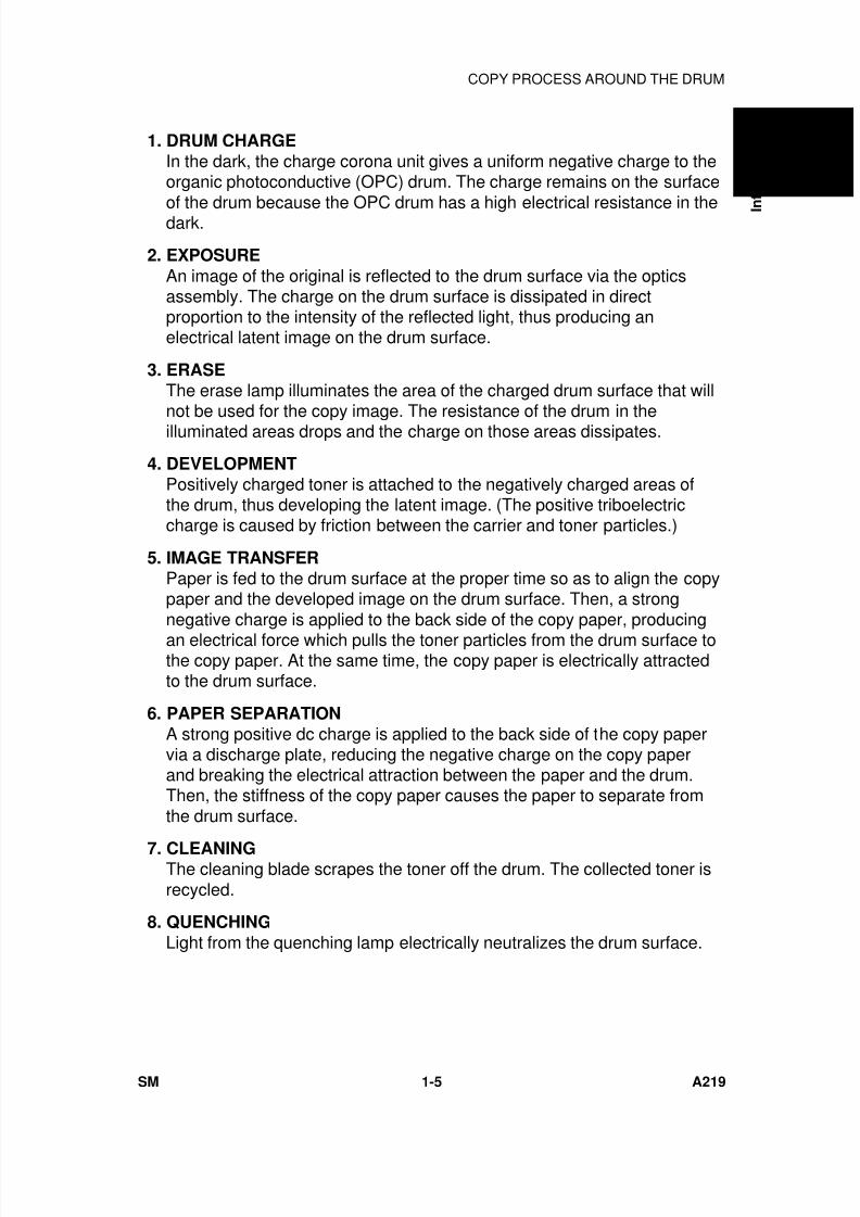
1. DRUM CHARGEIn the dark, the charge corona unit gives a uniform negative charge to theorganic photoconductive (OPC) drum. The charge remains on the surface
of the drum because the OPC drum has a high electrical resistance in thedark.
2. EXPOSURE
An image of the original is reflected to the drum surface via the opticsassembly. The charge on the drum surface is dissipated in directproportion to the intensity of the reflected light, thus producing anelectrical latent image on the drum surface.
3. ERASEThe erase lamp illuminates the area of the charged drum surface that willnot be used for the copy image. The resistance of the drum in theilluminated areas drops and the charge on those areas dissipates.
4. DEVELOPMENTPositively charged toner is attached to the negatively charged areas ofthe drum, thus developing the latent image. (The positive triboelectriccharge is caused by friction between the carrier and toner particles.)
5. IMAGE TRANSFERPaper is fed to the drum surface at the proper time so as to align the copypaper and the developed image on the drum surface. Then, a strongnegative charge is applied to the back side of the copy paper, producingan electrical force which pulls the toner particles from the drum surface tothe copy paper. At the same time, the copy paper is electrically attractedto the drum surface.
6. PAPER SEPARATIONA strong positive dc charge is applied to the back side of the copy papervia a discharge plate, reducing the negative charge on the copy paperand breaking the electrical attraction between the paper and the drum.Then, the stiffness of the copy paper causes the paper to separate fromthe drum surface.
7. CLEANINGThe cleaning blade scrapes the toner off the drum. The collected toner isrecycled.
8. QUENCHINGLight from the quenching lamp electrically neutralizes the drum surface.
O v e r a l l
I
n f o r m a t i o n
COPY PROCESS AROUND THE DRUM
SM 1-5 A219
7/18/2019 A219 245 B019 4015 3813 Service
http://slidepdf.com/reader/full/a219-245-b019-4015-3813-service 35/372
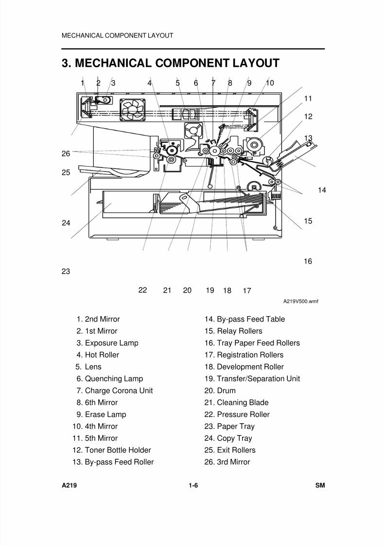
3. MECHANICAL COMPONENT LAYOUT
7
19
1098654321
16
15
14
13
12
11
22 21 20 1718
25
26
23
24
A219V500.wmf
1. 2nd Mirror
2. 1st Mirror
3. Exposure Lamp
4. Hot Roller
5. Lens
6. Quenching Lamp 7. Charge Corona Unit
8. 6th Mirror
9. Erase Lamp
10. 4th Mirror
11. 5th Mirror
12. Toner Bottle Holder
13. By-pass Feed Roller
14. By-pass Feed Table
15. Relay Rollers
16. Tray Paper Feed Rollers
17. Registration Rollers
18. Development Roller
19. Transfer/Separation Unit20. Drum
21. Cleaning Blade
22. Pressure Roller
23. Paper Tray
24. Copy Tray
25. Exit Rollers
26. 3rd Mirror
MECHANICAL COMPONENT LAYOUT
A219 1-6 SM
7/18/2019 A219 245 B019 4015 3813 Service
http://slidepdf.com/reader/full/a219-245-b019-4015-3813-service 36/372
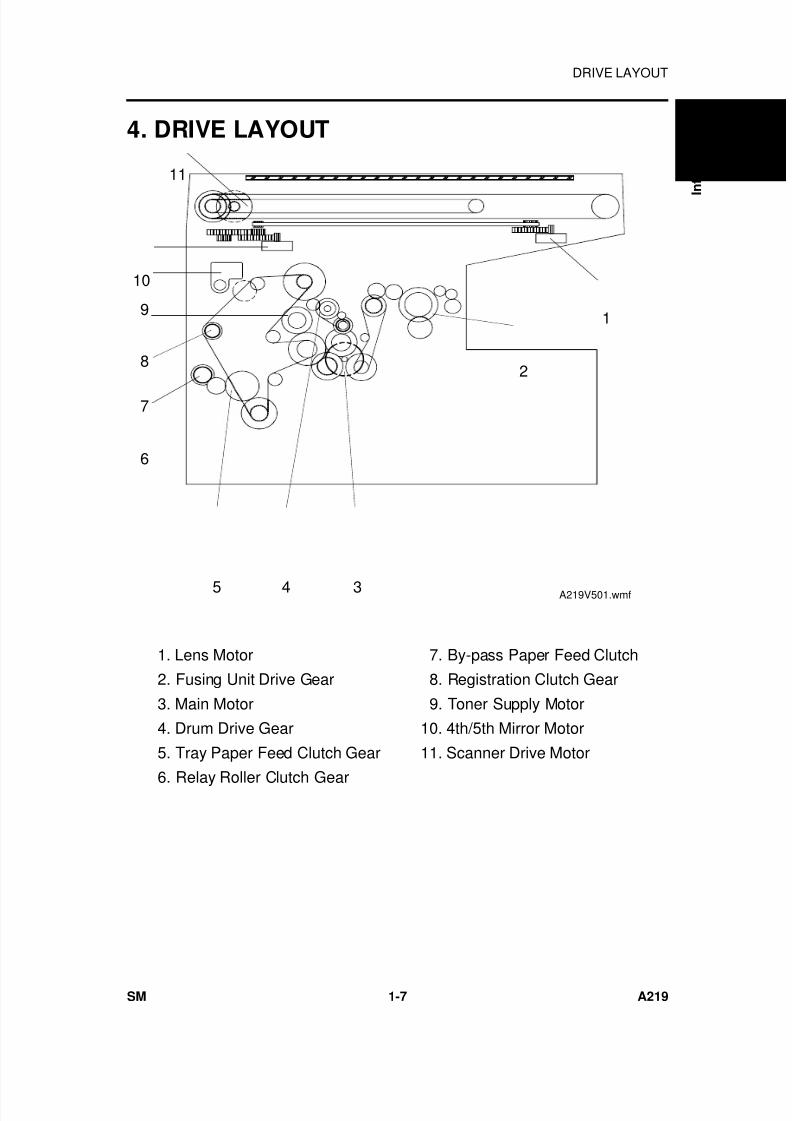
4. DRIVE LAYOUT
1. Lens Motor
2. Fusing Unit Drive Gear
3. Main Motor
4. Drum Drive Gear
5. Tray Paper Feed Clutch Gear
6. Relay Roller Clutch Gear
7. By-pass Paper Feed Clutch
8. Registration Clutch Gear
9. Toner Supply Motor
10. 4th/5th Mirror Motor
11. Scanner Drive Motor
1
2
9
8
7
6
5 4 3
11
10
A219V501.wmf
O v e r a l l
I
n f o r m a t i o n
DRIVE LAYOUT
SM 1-7 A219
7/18/2019 A219 245 B019 4015 3813 Service
http://slidepdf.com/reader/full/a219-245-b019-4015-3813-service 37/372
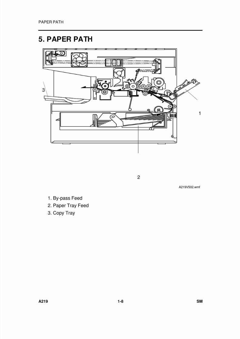
5. PAPER PATH
1
2
3
A219V502.wmf
1. By-pass Feed
2. Paper Tray Feed
3. Copy Tray
PAPER PATH
A219 1-8 SM
7/18/2019 A219 245 B019 4015 3813 Service
http://slidepdf.com/reader/full/a219-245-b019-4015-3813-service 38/372
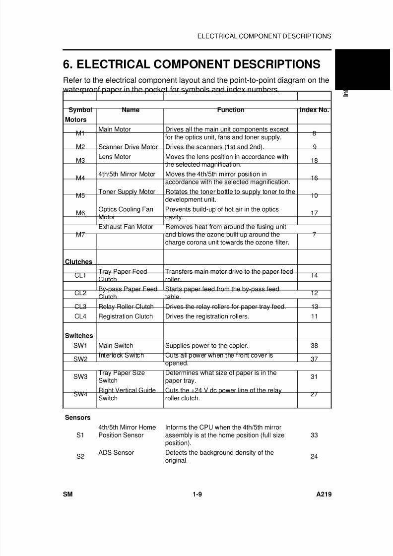
6. ELECTRICAL COMPONENT DESCRIPTIONS
Refer to the electrical component layout and the point-to-point diagram on thewaterproof paper in the pocket for symbols and index numbers.
Symbol Name Function Index No.
Motors
M1Main Motor Drives all the main unit components except
for the optics unit, fans and toner supply.8
M2 Scanner Drive Motor Drives the scanners (1st and 2nd). 9
M3 Lens Motor Moves the lens position in accordance withthe selected magnification.
18
M44th/5th Mirror Motor Moves the 4th/5th mirror position in
accordance with the selected magnification.16
M5 Toner Supply Motor Rotates the toner bottle to supply toner to thedevelopment unit. 10
M6 Optics Cooling FanMotor
Prevents build-up of hot air in the opticscavity.
17
M7Exhaust Fan Motor Removes heat from around the fusing unit
and blows the ozone built up around thecharge corona unit towards the ozone filter.
7
Clutches
CL1Tray Paper FeedClutch
Transfers main motor drive to the paper feedroller.
14
CL2 By-pass Paper FeedClutch Starts paper feed from the by-pass feedtable. 12
CL3 Relay Roller Clutch Drives the relay rollers for paper tray feed. 13
CL4 Registration Clutch Drives the registration rollers. 11
Switches
SW1 Main Switch Supplies power to the copier. 38
SW2Interlock Switch Cuts all power when the front cover is
opened.37
SW3Tray Paper SizeSwitch
Determines what size of paper is in thepaper tray.
31
SW4Right Vertical GuideSwitch
Cuts the +24 V dc power line of the relayroller clutch.
27
Sensors
S14th/5th Mirror HomePosition Sensor
Informs the CPU when the 4th/5th mirrorassembly is at the home position (full sizeposition).
33
S2ADS Sensor Detects the background density of the
original.24
O v e r a l l
I
n f o r m a t i o n
ELECTRICAL COMPONENT DESCRIPTIONS
SM 1-9 A219
7/18/2019 A219 245 B019 4015 3813 Service
http://slidepdf.com/reader/full/a219-245-b019-4015-3813-service 39/372
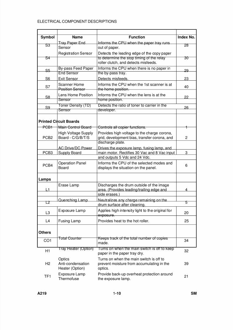
Symbol Name Function Index No.
S3Tray Paper EndSensor
Informs the CPU when the paper tray runsout of paper.
28
S4
Registration Sensor Detects the leading edge of the copy paper
to determine the stop timing of the relayroller clutch, and detects misfeeds.
30
S5By-pass Feed PaperEnd Sensor
Informs the CPU when there is no paper inthe by-pass tray.
29
S6 Exit Sensor Detects misfeeds. 23
S7Scanner HomePosition Sensor
Informs the CPU when the 1st scanner is atthe home position.
40
S8 Lens Home PositionSensor
Informs the CPU when the lens is at thehome position.
22
S9Toner Density (TD)Sensor
Detects the ratio of toner to carrier in thedeveloper.
26
Printed Circuit Boards
PCB1 Main Control Board Controls all copier functions. 1
PCB2High Voltage SupplyBoard - C/G/B/T/S
Provides high voltage to the charge corona,grid, development bias, transfer corona, anddischarge plate.
2
PCB3AC Drive/DC PowerSupply Board
Drives the exposure lamp, fusing lamp, andmain motor. Rectifies 30 Vac and 8 Vac inputand outputs 5 Vdc and 24 Vdc.
3
PCB4Operation PanelBoard
Informs the CPU of the selected modes anddisplays the situation on the panel.
6
Lamps
L1Erase Lamp Discharges the drum outside of the image
area. (Provides leading/trailing edge andside erases.)
4
L2Quenching Lamp Neutralizes any charge remaining on the
drum surface after cleaning.5
L3Exposure Lamp Applies high intensity light to the original for
exposure.20
L4 Fusing Lamp Provides heat to the hot roller. 25
Others
CO1Total Counter Keeps track of the total number of copies
made.34
H1Tray Heater (Option) Turns on when the main switch is off to keep
paper in the paper tray dry.32
H2OpticsAnti-condensationHeater (Option)
Turns on when the main switch is off toprevent moisture from accumulating in theoptics.
39
TF1Exposure LampThermofuse
Provide back-up overheat protection aroundthe exposure lamp.
21
ELECTRICAL COMPONENT DESCRIPTIONS
A219 1-10 SM

7/18/2019 A219 245 B019 4015 3813 Service
http://slidepdf.com/reader/full/a219-245-b019-4015-3813-service 40/372
Symbol Name Function Index No.
TF2Fusing Thermofuse Provide back-up overheat protection in the
fusing unit.36
TH1
Fusing Thermistor Monitors the temperature around the
exposure lamp for overheat protection. 35
TH2 Optics Thermistor Monitors the temperature around theexposure lamp for overheat protection.
19
TRTransformer Steps down the wall voltage to 30 Vac and 8
Vac.15
O v e r a l l
I
n f o r m a t i o n
ELECTRICAL COMPONENT DESCRIPTIONS
SM 1-11 A219

7/18/2019 A219 245 B019 4015 3813 Service
http://slidepdf.com/reader/full/a219-245-b019-4015-3813-service 41/372

7/18/2019 A219 245 B019 4015 3813 Service
http://slidepdf.com/reader/full/a219-245-b019-4015-3813-service 42/372
DETAILED DESCRIPTIONS

7/18/2019 A219 245 B019 4015 3813 Service
http://slidepdf.com/reader/full/a219-245-b019-4015-3813-service 43/372
7/18/2019 A219 245 B019 4015 3813 Service
http://slidepdf.com/reader/full/a219-245-b019-4015-3813-service 44/372
1. DRUM
1.1 OPC DRUM CHARACTERISTICS
The OPC (Organic Photoconductor) drum used in this copier is small indiameter (30 mm), ensuring good paper separation. An OPC drum has thefollowing characteristics.
1. The drum is able to accept a high negative electrical charge in the dark.(The electrical resistance of a photoconductor is high in the absence oflight.)
2. It dissipates the electrical charge when exposed to light.(Exposure to light greatly increases the conductivity of a photoconductor.)
3. The amount of charge dissipated is in direct proportion to the intensity of
the light. That is, where stronger light is directed to the photoconductorsurface, a smaller voltage remains on the drum.
4. An OPC drum is less sensitive to changes in temperature (whencompared to selenium F type drums).
5. During the drum’s life, drum residual voltage gradually increases and thephotoconductive surface becomes worn. Therefore, some compensationfor these characteristics is required.
D e t a i l e d
D e s c r i p t i o n s
DRUM
SM 2-1 A219
7/18/2019 A219 245 B019 4015 3813 Service
http://slidepdf.com/reader/full/a219-245-b019-4015-3813-service 45/372
1.2 DRIVE MECHANISM
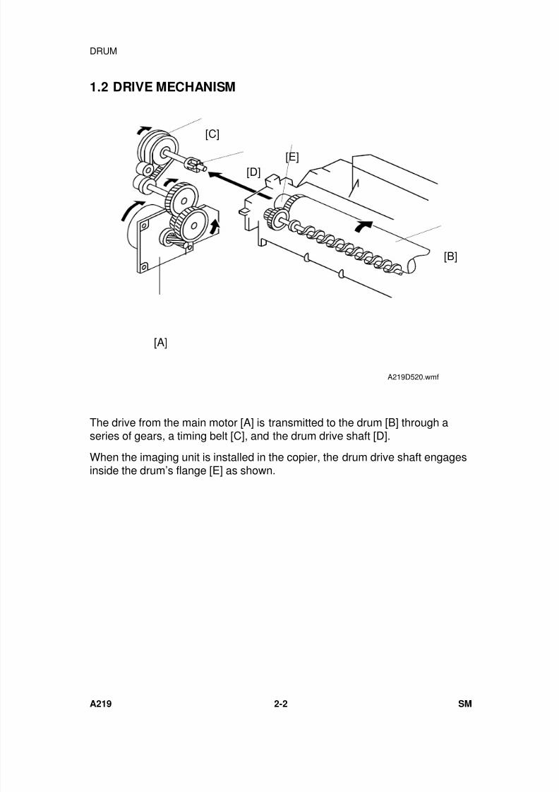
The drive from the main motor [A] is transmitted to the drum [B] through aseries of gears, a timing belt [C], and the drum drive shaft [D].
When the imaging unit is installed in the copier, the drum drive shaft engagesinside the drum’s flange [E] as shown.
[B]
[A]
[C]
[D][E]
A219D520.wmf
DRUM
A219 2-2 SM
7/18/2019 A219 245 B019 4015 3813 Service
http://slidepdf.com/reader/full/a219-245-b019-4015-3813-service 46/372
2. CHARGE
2.1 OVERVIEW
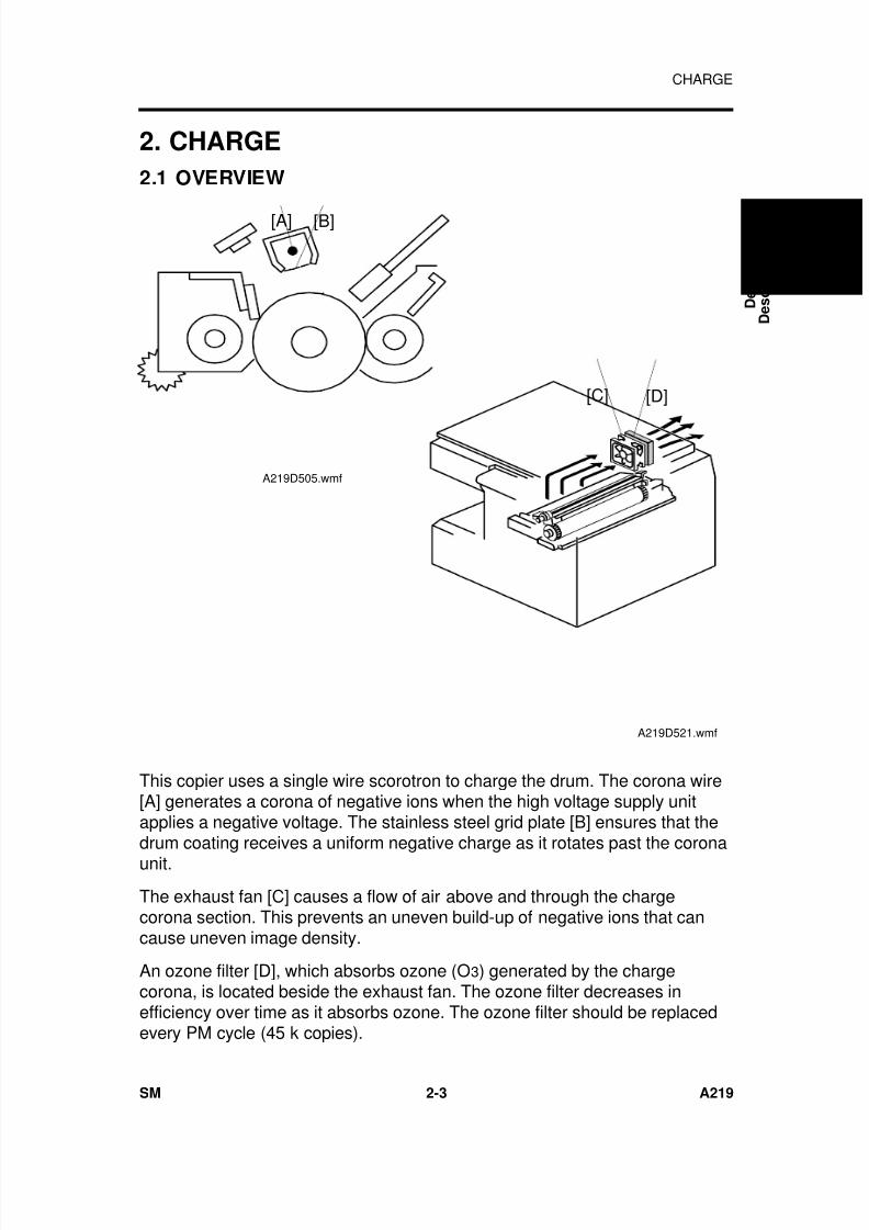
This copier uses a single wire scorotron to charge the drum. The corona wire[A] generates a corona of negative ions when the high voltage supply unitapplies a negative voltage. The stainless steel grid plate [B] ensures that thedrum coating receives a uniform negative charge as it rotates past the coronaunit.
The exhaust fan [C] causes a flow of air above and through the chargecorona section. This prevents an uneven build-up of negative ions that cancause uneven image density.
An ozone filter [D], which absorbs ozone (O3) generated by the chargecorona, is located beside the exhaust fan. The ozone filter decreases inefficiency over time as it absorbs ozone. The ozone filter should be replacedevery PM cycle (45 k copies).
[A] [B]
A219D505.wmf
[C] [D]
A219D521.wmf
D e t a i l e d
D e s c r i p t i o n s
CHARGE
SM 2-3 A219

7/18/2019 A219 245 B019 4015 3813 Service
http://slidepdf.com/reader/full/a219-245-b019-4015-3813-service 47/372
2.2 CHARGE CORONA WIRE CLEANER MECHANISM
Pads [A] move along the charge corona wire as the wire cleaner knob [B] ismanually slid in and out.
The cleaner pad bracket [C] is connected to the wire cleaner knob. When theknob is pulled out, the pads move into contact with the corona wire as shown,since the casing [D] is narrower away from the home position.
The pads move away from the wire when the wire cleaner knob is fullyinserted and the pad bracket is pushed back to the home position.
After copier installation, the key operator should be instructed to use this
mechanism when copies have white streaks or uneven image density.Instruct the operator to firmly push the pad bracket into the home position.Poor copy quality will result if the cleaning pads remain in contact with thecharge corona wire.
[A]
[B]
[D]
[C]
A219D536.wmf
CHARGE
A219 2-4 SM

7/18/2019 A219 245 B019 4015 3813 Service
http://slidepdf.com/reader/full/a219-245-b019-4015-3813-service 48/372
2.3 CHARGE CORONA CIRCUIT
The main board supplies +24 V to the high voltage supply board at CN102-7.After the key is pressed, the CPU drops CN102-5 from +5V to LOW.This activates the charge corona circuit which applies a high negative voltageof approximately –5 k volts to the charge corona wire. The corona wire thengenerates a negative corona charge.
The grid plate limits the charge voltage to ensure that the charge does notfluctuate and that an even charge is applied to the entire drum surface. Thegrid plate is connected to ground through a zener diode in the high voltagesupply unit. The grid plate drains any charge in excess of –910 V, which isdischarged to ground through the zener diode.
DC/DCConverter
CN102-7
Drum
B
ZenerDiode
Protect ionCircuit
DC/DCConverter
DC/DCConverter
DC/DC
Converter
G N DCN102-6
CN102-4
CN102-3
CN102-2
CN102-1
24 V
C Trigger
T Trigger
B - P W M
S Trigger
S
T
G C
5 V
4.7 k
Main Board High Voltage Supply Board
CN102-5
A219D506.wmf
D e t a i l e d
D e s c r i p t i o n s
CHARGE
SM 2-5 A219
7/18/2019 A219 245 B019 4015 3813 Service
http://slidepdf.com/reader/full/a219-245-b019-4015-3813-service 49/372
3. OPTICS
3.1 OVERVIEW
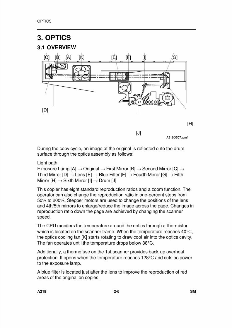
During the copy cycle, an image of the original is reflected onto the drumsurface through the optics assembly as follows:
Light path:
Exposure Lamp [A] → Original → First Mirror [B] → Second Mirror [C] →Third Mirror [D] → Lens [E] → Blue Filter [F] → Fourth Mirror [G] → FifthMirror [H] → Sixth Mirror [I] → Drum [J]
This copier has eight standard reproduction ratios and a zoom function. Theoperator can also change the reproduction ratio in one-percent steps from50% to 200%. Stepper motors are used to change the positions of the lensand 4th/5th mirrors to enlarge/reduce the image across the page. Changes inreproduction ratio down the page are achieved by changing the scannerspeed.
The CPU monitors the temperature around the optics through a thermistorwhich is located on the scanner frame. When the temperature reaches 40°C,the optics cooling fan [K] starts rotating to draw cool air into the optics cavity.The fan operates until the temperature drops below 38°C.
Additionally, a thermofuse on the 1st scanner provides back-up overheatprotection. It opens when the temperature reaches 128°C and cuts ac powerto the exposure lamp.
A blue filter is located just after the lens to improve the reproduction of redareas of the original on copies.
[C][C] [A][B] [K] [E] [I] [G]
[H]
[J]
[D]
[F]
A219D507.wmf
OPTICS
A219 2-6 SM
7/18/2019 A219 245 B019 4015 3813 Service
http://slidepdf.com/reader/full/a219-245-b019-4015-3813-service 50/372
3.2 SCANNER DRIVE
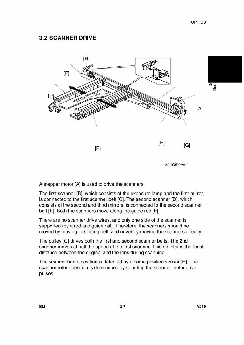
A stepper motor [A] is used to drive the scanners.
The first scanner [B], which consists of the exposure lamp and the first mirror,is connected to the first scanner belt [C]. The second scanner [D], whichconsists of the second and third mirrors, is connected to the second scannerbelt [E]. Both the scanners move along the guide rod [F].
There are no scanner drive wires, and only one side of the scanner issupported (by a rod and guide rail). Therefore, the scanners should bemoved by moving the timing belt, and never by moving the scanners directly.
The pulley [G] drives both the first and second scanner belts. The 2ndscanner moves at half the speed of the first scanner. This maintains the focaldistance between the original and the lens during scanning.
The scanner home position is detected by a home position sensor [H]. Thescanner return position is determined by counting the scanner motor drivepulses.
[H]
[F]
[D]
[B]
[C]
[E] [G]
[A]
A219D522.wmf
D e t a i l e d
D e s c r i p t i o n s
OPTICS
SM 2-7 A219
7/18/2019 A219 245 B019 4015 3813 Service
http://slidepdf.com/reader/full/a219-245-b019-4015-3813-service 51/372
3.3 LENS DRIVE
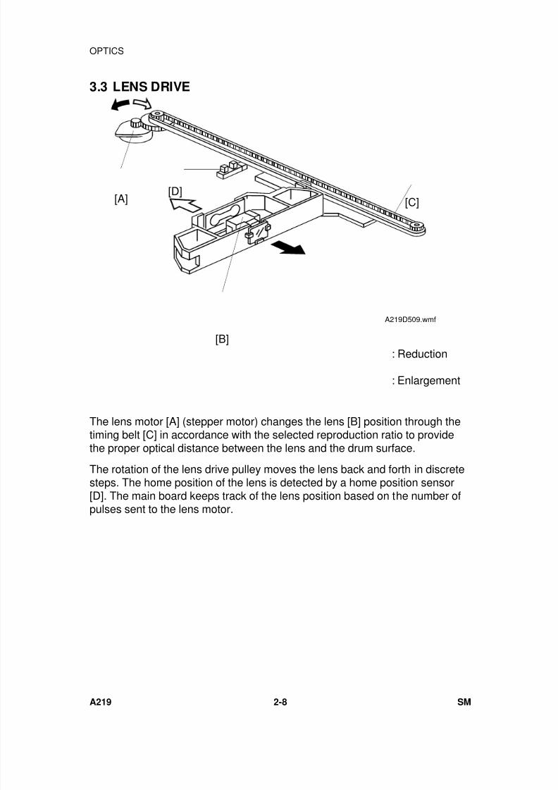
The lens motor [A] (stepper motor) changes the lens [B] position through thetiming belt [C] in accordance with the selected reproduction ratio to providethe proper optical distance between the lens and the drum surface.
The rotation of the lens drive pulley moves the lens back and forth in discretesteps. The home position of the lens is detected by a home position sensor[D]. The main board keeps track of the lens position based on the number ofpulses sent to the lens motor.
[C]
[B]
[D][A]
A219D509.wmf
: Reduction
: Enlargement
OPTICS
A219 2-8 SM
7/18/2019 A219 245 B019 4015 3813 Service
http://slidepdf.com/reader/full/a219-245-b019-4015-3813-service 52/372
3.4 4TH/5TH MIRROR DRIVE
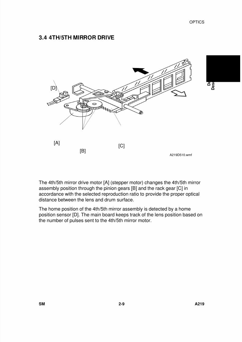
The 4th/5th mirror drive motor [A] (stepper motor) changes the 4th/5th mirrorassembly position through the pinion gears [B] and the rack gear [C] inaccordance with the selected reproduction ratio to provide the proper opticaldistance between the lens and drum surface.
The home position of the 4th/5th mirror assembly is detected by a homeposition sensor [D]. The main board keeps track of the lens position based onthe number of pulses sent to the 4th/5th mirror motor.
[D]
[C][B]
[A]
A219D510.wmf
D e t a i l e d
D e s c r i p t i o n s
OPTICS
SM 2-9 A219
7/18/2019 A219 245 B019 4015 3813 Service
http://slidepdf.com/reader/full/a219-245-b019-4015-3813-service 53/372
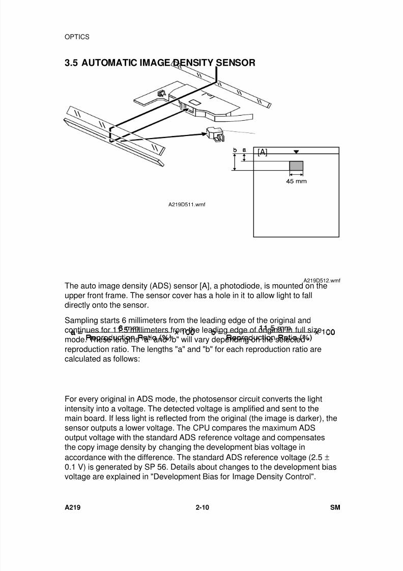
3.5 AUTOMATIC IMAGE DENSITY SENSOR
The auto image density (ADS) sensor [A], a photodiode, is mounted on the
upper front frame. The sensor cover has a hole in it to allow light to falldirectly onto the sensor.
Sampling starts 6 millimeters from the leading edge of the original andcontinues for 11.5 millimeters from the leading edge of original in full sizemode. These lengths "a" and "b" will vary depending on the selectedreproduction ratio. The lengths "a" and "b" for each reproduction ratio arecalculated as follows:
For every original in ADS mode, the photosensor circuit converts the lightintensity into a voltage. The detected voltage is amplified and sent to themain board. If less light is reflected from the original (the image is darker), thesensor outputs a lower voltage. The CPU compares the maximum ADSoutput voltage with the standard ADS reference voltage and compensatesthe copy image density by changing the development bias voltage inaccordance with the difference. The standard ADS reference voltage (2.5 ±0.1 V) is generated by SP 56. Details about changes to the development biasvoltage are explained in "Development Bias for Image Density Control".
A219D512.wmf
[A]
A219D511.wmf
OPTICS
A219 2-10 SM
7/18/2019 A219 245 B019 4015 3813 Service
http://slidepdf.com/reader/full/a219-245-b019-4015-3813-service 54/372
3.6 EXPOSURE LAMP VOLTAGE CONTROL
The main board controls the exposure lamp voltage through the ac drive/dcpower supply board. The exposure lamp voltage is based on the base lamp
voltage and various correction factors. The method of control is differentdepending on whether the image density is manually selected or the autoimage density mode is selected.
The exposure lamp voltage is determined by the following factors:
Lamp Voltage = Base Lamp Voltage Setting (SP48)+
*Image Density Adjustment Factor (SP34)+
*Manual Image Density Setting Factor
+VL Correction 1 Factor (SP62)+
VL Correction 2 Factor+
Reproduction Ratio Correction Factor
*NOTE: SP34 (Image Density Adjustment Factor) is applied for ADS modeonly.The "Manual Image Density Factor" is applied for manual ID mode
only.
1) Base Lamp Voltage Setting
The lamp voltage is determined by the SP48 setting.
Base Lamp Voltage = SP48 setting x 0.5 (120 V machines)SP48 setting x 1.0 (230 V machines)
The default setting is: 140 = 70 V (120 V machines)140 = 140 V (230 V machines)
The current lamp voltage (after all correction factors are included) can beviewed with SP 51.
D e t a i l e d
D e s c r i p t i o n s
OPTICS
SM 2-11 A219
7/18/2019 A219 245 B019 4015 3813 Service
http://slidepdf.com/reader/full/a219-245-b019-4015-3813-service 55/372
2) Image Density Adjustment Factor (SP34)
Depending on the SP34 setting, the development bias and the exposurelamp settings are increased or decreased during ADS mode.
SP34 Setting Setting Dev. Bias Exposure Lamp
0 Normal 0 01 Light –40 V 02 Dark +40 V 03 Lightest –40 V +4 steps4 Darkest +40 V –4 steps
1 step = 0.5 V (120 V machines) or 1.0 V (230 V machines)
3) Manual Image Density Setting FactorDepending on the manual image density setting on the operation panel, theexposure lamp voltage is changed as shown in the table below:
Manual IDLevel
1 2 3 4 5 6 7
ExposureLamp VoltageFactor
V0 – 6steps
V0 – 4steps
V0 – 2steps
V0V0 + 2steps
V0 + 6steps
V0 + 12steps
Development
Bias Voltage(Volts)
–200 –200 –200 –200 –200 –240 –240
V0: Base lamp voltage setting (SP48)
1 step = 0.5 V (120 V machines) or 1.0 V (230 V machines)
LighterDarker
OPTICS
A219 2-12 SM
7/18/2019 A219 245 B019 4015 3813 Service
http://slidepdf.com/reader/full/a219-245-b019-4015-3813-service 56/372
4) VL Correction 1 Factor
The light intensity may decrease because of dust accumulated on the opticalparts. Additionally, the drum sensitivity gradually decreases during the drum’s
life. This may cause dirty background on copies. To compensate for this, VLcorrections 1 and 2 are done.
The exposure lamp voltage is increased by two steps at the set copy countinterval (a step is +2.0 V for 230 V machines, and +1 V for 120 V machines).The table below shows the relationship between the SP setting and the copyinterval.
SP62 Setting VL Correction Interval
0 2 steps/8,000 copies1 2 steps/6,000 copies2 2 steps/4,000 copies3 2 steps/2,000 copies4 2 steps/1,000 copies5 No correction
(Default setting: 2)
VL correction 1 compensates for the decrease of drum sensitivity and thedecrease in reflectivity of the 4th, 5th, and 6th mirrors due to dust.
5) VL Correction 2 Factor
VL correction 2 compensates for dust on the lens and mirrors 1 to 3, but isindependent of the drum condition.
The ADS sensor receives the light reflected through the 1st, 2nd and 3rdmirrors from the white plate located under the middle of the left scale. Thephotosensor circuit converts this light intensity into a voltage. The CPU storesthis voltage in memory as the white plate reference voltage. This is doneevery time SP56 (ADS reference voltage adjustment) is done, beforesampling starts for the ADS sensor adjustment.
Every 500 copies, the machine reads the intensity of light reflected from thewhite plate and compares it with the white plate reference voltage.
If the measured voltage difference is more than 0.1 volt, +2 steps will beadded to the exposure lamp setting as the VL correction 2 factor.
The sum of VL correction factors 1 and 2 cannot exceed +40 steps.
VL correction factors 1 and 2 are automatically reset every time the lightintensity is adjusted with SP48. (SP56 must be done immediately after SP48;see Service Remarks for details.)
D e t a i l e d
D e s c r i p t i o n s
OPTICS
SM 2-13 A219
7/18/2019 A219 245 B019 4015 3813 Service
http://slidepdf.com/reader/full/a219-245-b019-4015-3813-service 57/372
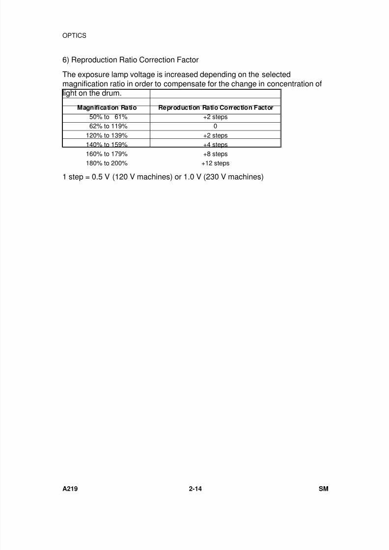
6) Reproduction Ratio Correction Factor
The exposure lamp voltage is increased depending on the selectedmagnification ratio in order to compensate for the change in concentration of
light on the drum.Magnification Ratio Reproduction Ratio Correction Factor
50% to 61% +2 steps 62% to 119% 0120% to 139% +2 steps140% to 159% +4 steps160% to 179% +8 steps180% to 200% +12 steps
1 step = 0.5 V (120 V machines) or 1.0 V (230 V machines)
OPTICS
A219 2-14 SM
7/18/2019 A219 245 B019 4015 3813 Service
http://slidepdf.com/reader/full/a219-245-b019-4015-3813-service 58/372
4. ERASE
4.1 OVERVIEW
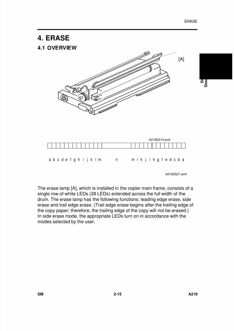
The erase lamp [A], which is installed in the copier main frame, consists of asingle row of white LEDs (38 LEDs) extended across the full width of thedrum. The erase lamp has the following functions: leading edge erase, sideerase and trail edge erase. (Trail edge erase begins after the trailing edge ofthe copy paper; therefore, the trailing edge of the copy will not be erased.)In side erase mode, the appropriate LEDs turn on in accordance with themodes selected by the user.
[A]
A219D513.wmf
b c d e f g ha i j k l m m l k j i h g f e d c b an
A219D527.wmf
D e t a i l e d
D e s c r i p t i o n s
ERASE
SM 2-15 A219
7/18/2019 A219 245 B019 4015 3813 Service
http://slidepdf.com/reader/full/a219-245-b019-4015-3813-service 59/372
4.2 LEAD EDGE ERASE
The entire line of LEDs turn on when the main motor turns on. They stay onuntil the erase margin slightly overlaps the lead edge of the original image
area on the drum (Lead Edge Erase Margin). This prevents the shadow ofthe original edge from being developed on the copy. At this point, side erasestarts. The width of the leading erase margin can be adjusted using SP41.
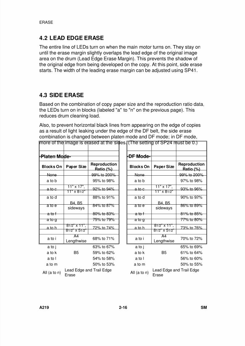
4.3 SIDE ERASE
Based on the combination of copy paper size and the reproduction ratio data,the LEDs turn on in blocks (labeled "a" to "n" on the previous page). Thisreduces drum cleaning load.
Also, to prevent horizontal black lines from appearing on the edge of copiesas a result of light leaking under the edge of the DF belt, the side erasecombination is changed between platen mode and DF mode; in DF mode,more of the image is erased at the sides. (The setting of SP24 must be 0.)
Blocks On Paper SizeReproduction
Ratio (%)
None 99% to 200%
a to b 95% to 98%
a to c11" x 17",11" x 81/2"
92% to 94%
a to d 88% to 91%
a to eB4, B5
sideways84% to 87%
a to f 80% to 83%a to g 75% to 79%
a to h81/2" x 11",81/2" x 51/2"
72% to 74%
a to i
A4
Lengthwise 68% to 71%a to j 63% to 67%a to k B5 59% to 62%a to l 54% to 58%
a to m 50% to 53%
All (a to n)Lead Edge and Trail EdgeErase
-Platen Mode-
Blocks On Paper SizeReproduction
Ratio (%)
None 99% to 200%
a to b 97% to 98%
a to c11" x 17",11" x 81/2"
93% to 96%
a to d 90% to 92%
a to eB4, B5
sideways86% to 89%
a to f 81% to 85%a to g 77% to 80%
a to h81/2" x 11",81/2" x 51/2"
73% to 76%
a to i
A4
Lengthwise 70% to 72%a to j 65% to 69%a to k B5 61% to 64%a to l 56% to 60%
a to m 50% to 55%
All (a to n)Lead Edge and Trail EdgeErase
-DF Mode-
ERASE
A219 2-16 SM

7/18/2019 A219 245 B019 4015 3813 Service
http://slidepdf.com/reader/full/a219-245-b019-4015-3813-service 60/372
4.4 TRAILING EDGE ERASE
This minimizes toner consumption.
The entire line of LEDs turns on when the drum has turned 9 mm at the endof scanning (about 100 ms). The LEDs stay on to erase the leading edge ofthe latent image in the next copy cycle. After the final copy, the erase lampsturn off at the same time as the main motor.
D e t a i l e d
D e s c r i p t i o n s
ERASE
SM 2-17 A219
7/18/2019 A219 245 B019 4015 3813 Service
http://slidepdf.com/reader/full/a219-245-b019-4015-3813-service 61/372
5. DEVELOPMENT
5.1 OVERVIEW
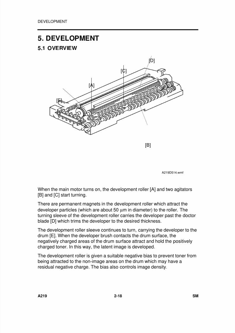
When the main motor turns on, the development roller [A] and two agitators[B] and [C] start turning.
There are permanent magnets in the development roller which attract thedeveloper particles (which are about 50 µm in diameter) to the roller. Theturning sleeve of the development roller carries the developer past the doctorblade [D] which trims the developer to the desired thickness.
The development roller sleeve continues to turn, carrying the developer to thedrum [E]. When the developer brush contacts the drum surface, thenegatively charged areas of the drum surface attract and hold the positivelycharged toner. In this way, the latent image is developed.
The development roller is given a suitable negative bias to prevent toner frombeing attracted to the non-image areas on the drum which may have aresidual negative charge. The bias also controls image density.
[D]
[B]
[E]
[A]
[C]
A219D514.wmf
DEVELOPMENT
A219 2-18 SM
7/18/2019 A219 245 B019 4015 3813 Service
http://slidepdf.com/reader/full/a219-245-b019-4015-3813-service 62/372
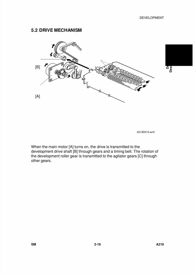
5.2 DRIVE MECHANISM
When the main motor [A] turns on, the drive is transmitted to thedevelopment drive shaft [B] through gears and a timing belt. The rotation ofthe development roller gear is transmitted to the agitator gears [C] throughother gears.
[A]
[B] [C]
A219D515.wmf
D e t a i l e d
D e s c r i p t i o n s
DEVELOPMENT
SM 2-19 A219
7/18/2019 A219 245 B019 4015 3813 Service
http://slidepdf.com/reader/full/a219-245-b019-4015-3813-service 63/372
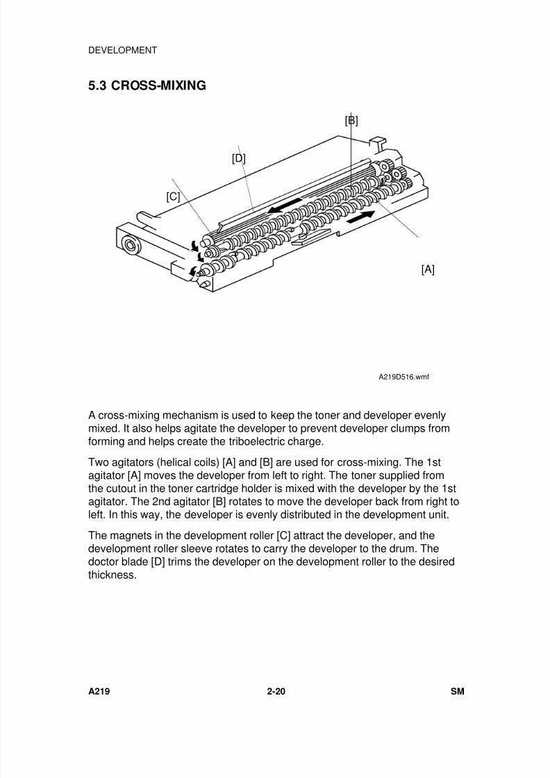
5.3 CROSS-MIXING
A cross-mixing mechanism is used to keep the toner and developer evenlymixed. It also helps agitate the developer to prevent developer clumps fromforming and helps create the triboelectric charge.
Two agitators (helical coils) [A] and [B] are used for cross-mixing. The 1stagitator [A] moves the developer from left to right. The toner supplied fromthe cutout in the toner cartridge holder is mixed with the developer by the 1stagitator. The 2nd agitator [B] rotates to move the developer back from right toleft. In this way, the developer is evenly distributed in the development unit.
The magnets in the development roller [C] attract the developer, and thedevelopment roller sleeve rotates to carry the developer to the drum. Thedoctor blade [D] trims the developer on the development roller to the desiredthickness.
[A]
[B]
[C]
[D]
A219D516.wmf
DEVELOPMENT
A219 2-20 SM

7/18/2019 A219 245 B019 4015 3813 Service
http://slidepdf.com/reader/full/a219-245-b019-4015-3813-service 64/372
5.4 DEVELOPMENT BIAS FOR IMAGE DENSITY CONTROL
The image density is controlled by changing two items: the amount of biasvoltage applied to the development roller sleeve, and the amount of voltage
applied to the exposure lamp.Applying a bias voltage to the development sleeve reduces the potentialbetween the development roller and the drum, thereby reducing the amountof toner transferred. As the bias voltage becomes greater, the copy becomeslighter.
The method of control depends on whether the image density is manuallyselected or auto image density is used.
The development bias voltage applied to the development roller sleeve hasthe following factors:
Development bias voltage = Base Bias Voltage(Manual or auto image density mode)
+*Image Bias Adjustment Factor (SP33)
+*Image Density Adjustment Factor (SP34)
+Drum Residual Voltage (VR) Correction Factor
*NOTE: Image Bias Adjustment Factor (SP33) is applied for manual ID modeonly.Image Density Adjustment Factor (SP34) is applied for ADS modeonly.
D e t a i l e d
D e s c r i p t i o n s
DEVELOPMENT
SM 2-21 A219
7/18/2019 A219 245 B019 4015 3813 Service
http://slidepdf.com/reader/full/a219-245-b019-4015-3813-service 65/372
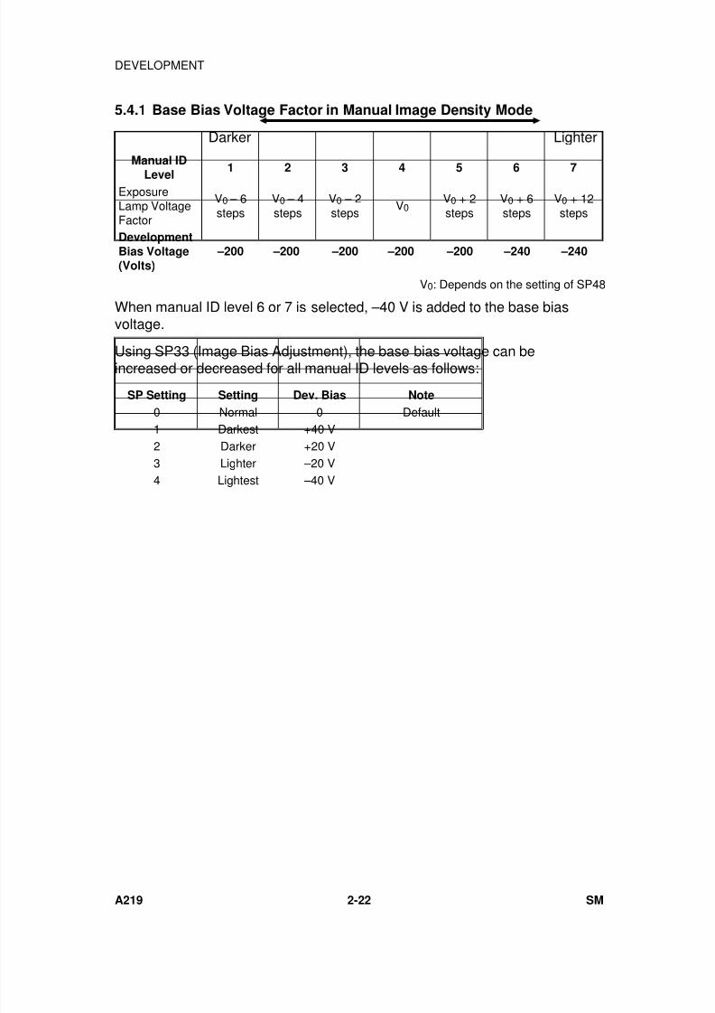
5.4.1 Base Bias Voltage Factor in Manual Image Density Mode
Manual ID
Level1 2 3 4 5 6 7
ExposureLamp VoltageFactor
V0 – 6steps
V0 – 4steps
V0 – 2steps
V0V0 + 2steps
V0 + 6steps
V0 + 12steps
DevelopmentBias Voltage(Volts)
–200 –200 –200 –200 –200 –240 –240
V0: Depends on the setting of SP48
When manual ID level 6 or 7 is selected, –40 V is added to the base biasvoltage.
Using SP33 (Image Bias Adjustment), the base bias voltage can beincreased or decreased for all manual ID levels as follows:
SP Setting Setting Dev. Bias Note
0 Normal 0 Default1 Darkest +40 V2 Darker +20 V3 Lighter –20 V4 Lightest –40 V
LighterDarker
DEVELOPMENT
A219 2-22 SM
7/18/2019 A219 245 B019 4015 3813 Service
http://slidepdf.com/reader/full/a219-245-b019-4015-3813-service 66/372
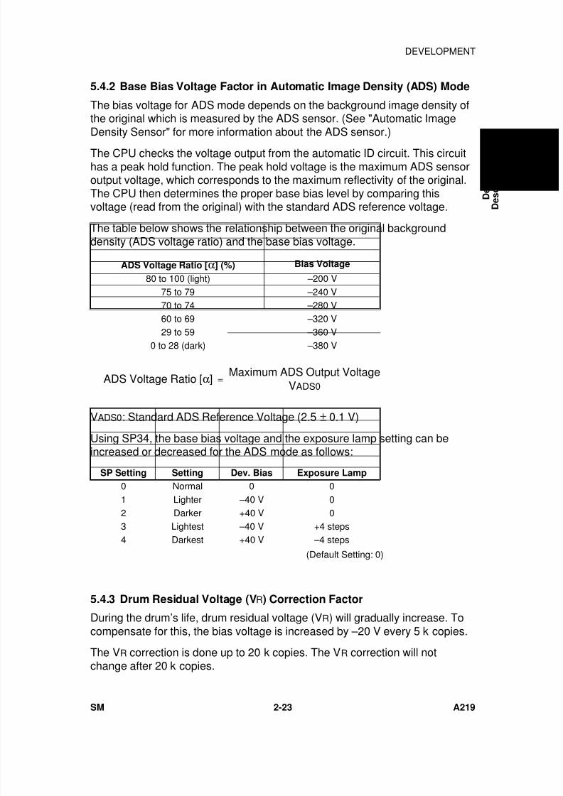
5.4.2 Base Bias Voltage Factor in Automatic Image Density (ADS) Mode
The bias voltage for ADS mode depends on the background image density ofthe original which is measured by the ADS sensor. (See "Automatic ImageDensity Sensor" for more information about the ADS sensor.)
The CPU checks the voltage output from the automatic ID circuit. This circuithas a peak hold function. The peak hold voltage is the maximum ADS sensoroutput voltage, which corresponds to the maximum reflectivity of the original.The CPU then determines the proper base bias level by comparing thisvoltage (read from the original) with the standard ADS reference voltage.
The table below shows the relationship between the original backgrounddensity (ADS voltage ratio) and the base bias voltage.
ADS Voltage Ratio [α] (%) Bias Voltage
80 to 100 (light) –200 V75 to 79 –240 V70 to 74 –280 V60 to 69 –320 V29 to 59 –360 V
0 to 28 (dark) –380 V
ADS Voltage Ratio [α] = Maximum ADS Output Voltage
VADS0
VADS0: Standard ADS Reference Voltage (2.5 ± 0.1 V)
Using SP34, the base bias voltage and the exposure lamp setting can beincreased or decreased for the ADS mode as follows:
SP Setting Setting Dev. Bias Exposure Lamp
0 Normal 0 01 Lighter –40 V 02 Darker +40 V 03 Lightest –40 V +4 steps4 Darkest +40 V –4 steps
(Default Setting: 0)
5.4.3 Drum Residual Voltage (VR) Correction Factor
During the drum’s life, drum residual voltage (VR) will gradually increase. Tocompensate for this, the bias voltage is increased by –20 V every 5 k copies.
The VR correction is done up to 20 k copies. The VR correction will notchange after 20 k copies.
D e t a i l e d
D e s c r i p t i o n s
DEVELOPMENT
SM 2-23 A219
7/18/2019 A219 245 B019 4015 3813 Service
http://slidepdf.com/reader/full/a219-245-b019-4015-3813-service 67/372
5.5 DEVELOPMENT BIAS CIRCUIT
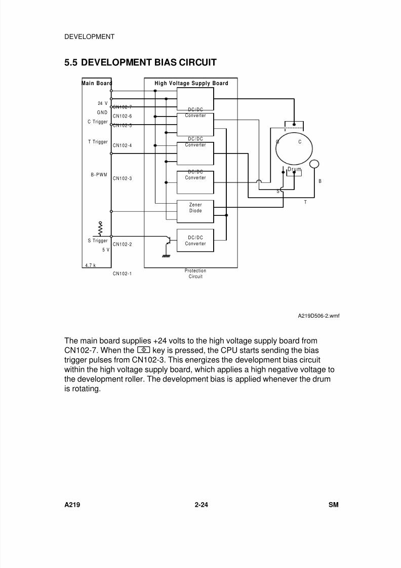
The main board supplies +24 volts to the high voltage supply board fromCN102-7. When the key is pressed, the CPU starts sending the biastrigger pulses from CN102-3. This energizes the development bias circuitwithin the high voltage supply board, which applies a high negative voltage tothe development roller. The development bias is applied whenever the drumis rotating.
DC/DCConverter
CN102-7
Drum
B
ZenerDiode
Protect ionCircuit
DC/DCConverter
DC/DCConverter
DC/DC
Converter
G N DCN102-6
CN102-4
CN102-3
CN102-2
CN102-1
24 V
C Trigger
T Trigger
B - P W M
S Trigger
S
T
G C
5 V
4.7 k
Main Board High Voltage Supply Board
CN102-5
A219D506-2.wmf
DEVELOPMENT
A219 2-24 SM
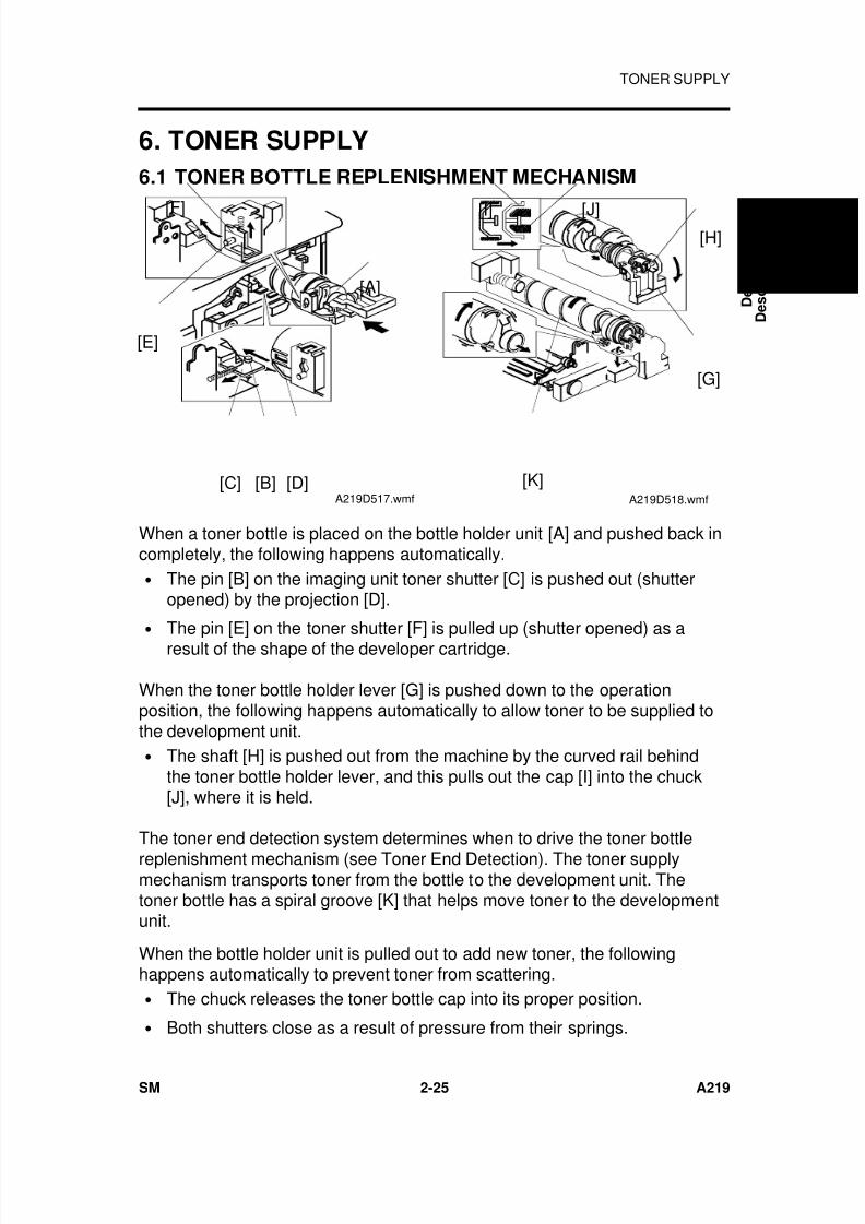
7/18/2019 A219 245 B019 4015 3813 Service
http://slidepdf.com/reader/full/a219-245-b019-4015-3813-service 68/372
6. TONER SUPPLY
6.1 TONER BOTTLE REPLENISHMENT MECHANISM
When a toner bottle is placed on the bottle holder unit [A] and pushed back incompletely, the following happens automatically.• The pin [B] on the imaging unit toner shutter [C] is pushed out (shutter
opened) by the projection [D].
•
The pin [E] on the toner shutter [F] is pulled up (shutter opened) as aresult of the shape of the developer cartridge.
When the toner bottle holder lever [G] is pushed down to the operationposition, the following happens automatically to allow toner to be supplied tothe development unit.• The shaft [H] is pushed out from the machine by the curved rail behind
the toner bottle holder lever, and this pulls out the cap [I] into the chuck[J], where it is held.
The toner end detection system determines when to drive the toner bottlereplenishment mechanism (see Toner End Detection). The toner supplymechanism transports toner from the bottle to the development unit. Thetoner bottle has a spiral groove [K] that helps move toner to the developmentunit.
When the bottle holder unit is pulled out to add new toner, the followinghappens automatically to prevent toner from scattering.• The chuck releases the toner bottle cap into its proper position.
• Both shutters close as a result of pressure from their springs.
[A]
[F]
[E]
[D][C] [B]A219D517.wmf
[K]
[G]
[H][I] [J]
A219D518.wmf
D e t a i l e d
D e s c r i p t i o n s
TONER SUPPLY
SM 2-25 A219
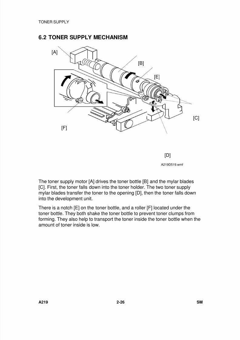
7/18/2019 A219 245 B019 4015 3813 Service
http://slidepdf.com/reader/full/a219-245-b019-4015-3813-service 69/372
6.2 TONER SUPPLY MECHANISM
The toner supply motor [A] drives the toner bottle [B] and the mylar blades[C]. First, the toner falls down into the toner holder. The two toner supplymylar blades transfer the toner to the opening [D], then the toner falls downinto the development unit.
There is a notch [E] on the toner bottle, and a roller [F] located under thetoner bottle. They both shake the toner bottle to prevent toner clumps fromforming. They also help to transport the toner inside the toner bottle when theamount of toner inside is low.
[A]
[E]
[B]
[C]
[D]
[F]
A219D519.wmf
TONER SUPPLY
A219 2-26 SM
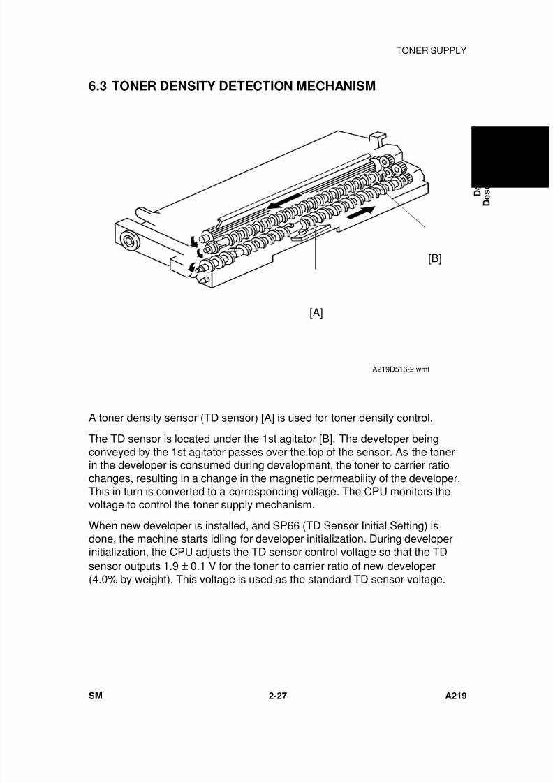
7/18/2019 A219 245 B019 4015 3813 Service
http://slidepdf.com/reader/full/a219-245-b019-4015-3813-service 70/372
6.3 TONER DENSITY DETECTION MECHANISM
A toner density sensor (TD sensor) [A] is used for toner density control.
The TD sensor is located under the 1st agitator [B]. The developer beingconveyed by the 1st agitator passes over the top of the sensor. As the tonerin the developer is consumed during development, the toner to carrier ratiochanges, resulting in a change in the magnetic permeability of the developer.This in turn is converted to a corresponding voltage. The CPU monitors thevoltage to control the toner supply mechanism.
When new developer is installed, and SP66 (TD Sensor Initial Setting) is
done, the machine starts idling for developer initialization. During developerinitialization, the CPU adjusts the TD sensor control voltage so that the TDsensor outputs 1.9 ± 0.1 V for the toner to carrier ratio of new developer(4.0% by weight). This voltage is used as the standard TD sensor voltage.
[B]
[A]
A219D516-2.wmf
D e t a i l e d
D e s c r i p t i o n s
TONER SUPPLY
SM 2-27 A219
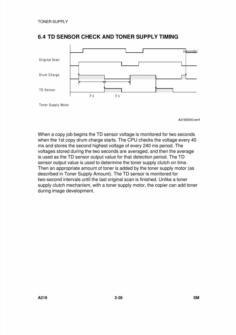
7/18/2019 A219 245 B019 4015 3813 Service
http://slidepdf.com/reader/full/a219-245-b019-4015-3813-service 71/372
6.4 TD SENSOR CHECK AND TONER SUPPLY TIMING
When a copy job begins the TD sensor voltage is monitored for two secondswhen the 1st copy drum charge starts. The CPU checks the voltage every 40ms and stores the second highest voltage of every 240 ms period. Thevoltages stored during the two seconds are averaged, and then the averageis used as the TD sensor output value for that detection period. The TDsensor output value is used to determine the toner supply clutch on time.Then an appropriate amount of toner is added by the toner supply motor (as
described in Toner Supply Amount). The TD sensor is monitored fortwo-second intervals until the last original scan is finished. Unlike a tonersupply clutch mechanism, with a toner supply motor, the copier can add tonerduring image development.
Orig ina l Scan
Drum Charge
TD Senso r
Toner Supply Motor
2 s
(seconds)
2 s
A219D540.wmf
TONER SUPPLY
A219 2-28 SM
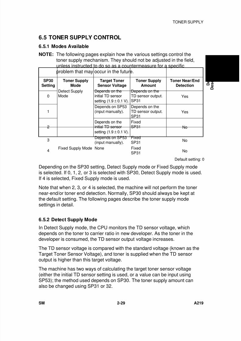
7/18/2019 A219 245 B019 4015 3813 Service
http://slidepdf.com/reader/full/a219-245-b019-4015-3813-service 72/372
6.5 TONER SUPPLY CONTROL
6.5.1 Modes Available
NOTE: The following pages explain how the various settings control the
toner supply mechanism. They should not be adjusted in the field,unless instructed to do so as a countermeasure for a specificproblem that may occur in the future.
SP30Setting
Toner SupplyMode
Target TonerSensor Voltage
Toner SupplyAmount
Toner Near/EndDetection
0Detect SupplyMode
Depends on theinitial TD sensorsetting (1.9 ± 0.1 V).
Depends on theTD sensor output.SP31
Yes
1Depends on SP53(input manually).
Depends on theTD sensor output.
SP31
Yes
2Depends on theinitial TD sensorsetting (1.9 ± 0.1 V).
FixedSP31 No
3Depends on SP53(input manually).
FixedSP31 No
4Fixed Supply Mode None Fixed
SP31 No
Default setting: 0
Depending on the SP30 setting, Detect Supply mode or Fixed Supply modeis selected. If 0, 1, 2, or 3 is selected with SP30, Detect Supply mode is used.
If 4 is selected, Fixed Supply mode is used.Note that when 2, 3, or 4 is selected, the machine will not perform the tonernear-end/or toner end detection. Normally, SP30 should always be kept atthe default setting. The following pages describe the toner supply modesettings in detail.
6.5.2 Detect Supply Mode
In Detect Supply mode, the CPU monitors the TD sensor voltage, whichdepends on the toner to carrier ratio in new developer. As the toner in thedeveloper is consumed, the TD sensor output voltage increases.
The TD sensor voltage is compared with the standard voltage (known as theTarget Toner Sensor Voltage), and toner is supplied when the TD sensoroutput is higher than this target voltage.
The machine has two ways of calculating the target toner sensor voltage(either the initial TD sensor setting is used, or a value can be input usingSP53); the method used depends on SP30. The toner supply amount canalso be changed using SP31 or 32.
D e t a i l e d
D e s c r i p t i o n s
TONER SUPPLY
SM 2-29 A219
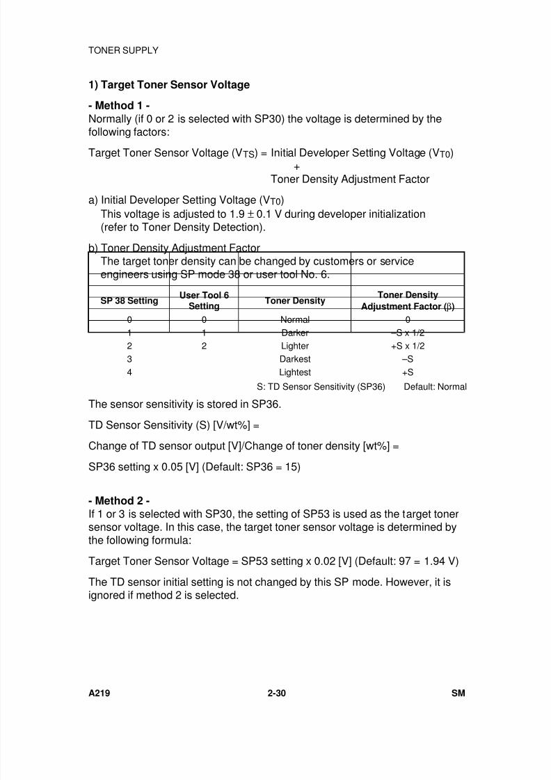
7/18/2019 A219 245 B019 4015 3813 Service
http://slidepdf.com/reader/full/a219-245-b019-4015-3813-service 73/372
1) Target Toner Sensor Voltage
- Method 1 -
Normally (if 0 or 2 is selected with SP30) the voltage is determined by the
following factors:Target Toner Sensor Voltage (VTS) = Initial Developer Setting Voltage (VT0)
+Toner Density Adjustment Factor
a) Initial Developer Setting Voltage (VT0) This voltage is adjusted to 1.9 ± 0.1 V during developer initialization (refer to Toner Density Detection).
b) Toner Density Adjustment Factor The target toner density can be changed by customers or service
engineers using SP mode 38 or user tool No. 6.
SP 38 SettingUser Tool 6
SettingToner Density
Toner Density
Adjustment Factor (β)
0 0 Normal 01 1 Darker –S x 1/22 2 Lighter +S x 1/23 Darkest –S4 Lightest +S
S: TD Sensor Sensitivity (SP36) Default: Normal
The sensor sensitivity is stored in SP36.TD Sensor Sensitivity (S) [V/wt%] =
Change of TD sensor output [V]/Change of toner density [wt%] =
SP36 setting x 0.05 [V] (Default: SP36 = 15)
- Method 2 -If 1 or 3 is selected with SP30, the setting of SP53 is used as the target tonersensor voltage. In this case, the target toner sensor voltage is determined by
the following formula:Target Toner Sensor Voltage = SP53 setting x 0.02 [V] (Default: 97 = 1.94 V)
The TD sensor initial setting is not changed by this SP mode. However, it isignored if method 2 is selected.
TONER SUPPLY
A219 2-30 SM
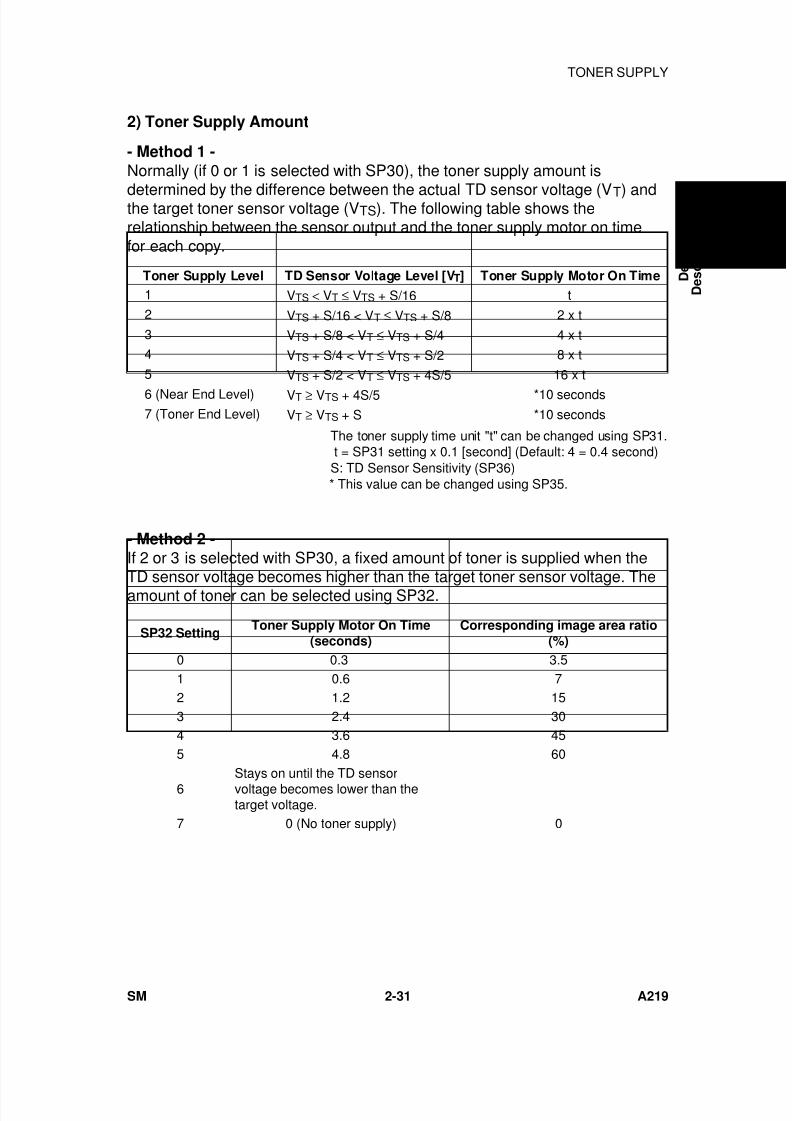
7/18/2019 A219 245 B019 4015 3813 Service
http://slidepdf.com/reader/full/a219-245-b019-4015-3813-service 74/372
2) Toner Supply Amount
- Method 1 -
Normally (if 0 or 1 is selected with SP30), the toner supply amount is
determined by the difference between the actual TD sensor voltage (VT) andthe target toner sensor voltage (VTS). The following table shows therelationship between the sensor output and the toner supply motor on timefor each copy.
Toner Supply Level TD Sensor Voltage Level [VT] Toner Supply Motor On Time
1 VTS < VT ≤ VTS + S/16 t
2 VTS + S/16 < VT ≤ VTS + S/8 2 x t
3 VTS + S/8 < VT ≤ VTS + S/4 4 x t 4 VTS + S/4 < VT ≤ VTS + S/2 8 x t
5 VTS + S/2 < VT ≤ VTS + 4S/5 16 x t
6 (Near End Level) VT ≥ VTS + 4S/5 *10 seconds 7 (Toner End Level) VT ≥ VTS + S *10 seconds
The toner supply time unit "t" can be changed using SP31. t = SP31 setting x 0.1 [second] (Default: 4 = 0.4 second) S: TD Sensor Sensitivity (SP36) * This value can be changed using SP35.
- Method 2 -If 2 or 3 is selected with SP30, a fixed amount of toner is supplied when the
TD sensor voltage becomes higher than the target toner sensor voltage. Theamount of toner can be selected using SP32.
SP32 SettingToner Supply Motor On Time
(seconds)Corresponding image area ratio
(%)
0 0.3 3.51 0.6 72 1.2 153 2.4 304 3.6 455 4.8 60
6 Stays on until the TD sensorvoltage becomes lower than thetarget voltage.
7 0 (No toner supply) 0
D e t a i l e d
D e s c r i p t i o n s
TONER SUPPLY
SM 2-31 A219
7/18/2019 A219 245 B019 4015 3813 Service
http://slidepdf.com/reader/full/a219-245-b019-4015-3813-service 75/372
6.5.3 Fixed Supply Mode
If 4 is selected with SP30, the TD sensor is not used for toner supply control.A fixed amount of toner is supplied every copy cycle. The toner supplyamount is determined by the SP32 setting.
6.5.4 Abnormal Condition in Toner Density Detection
If the output of the TD sensor goes below 0.2 volts (indicating far too muchtoner), the CPU determines that the toner density supply is abnormal. TheCPU changes from the detect supply mode to the fixed supply mode. At thesame time, either the Auto ID indicator or the selected manual ID level startsblinking, and the machine can be used. No SC code is generated. Under thiscondition, the machine will not perform the toner end detection.
If the value recovers above 0.2 volts, or the main switch is turned off and on,this condition is canceled and the toner density detection will recover to thetoner supply mode that was in use immediately before the abnormal conditionoccurred.
TONER SUPPLY
A219 2-32 SM
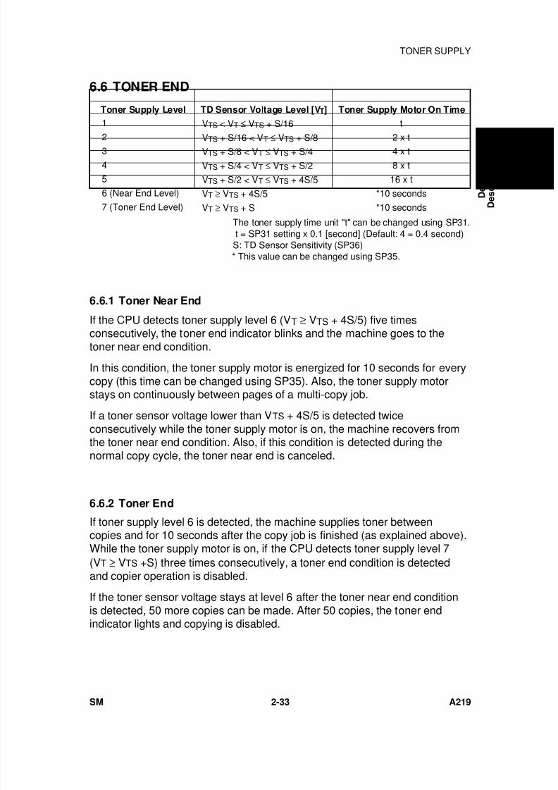
7/18/2019 A219 245 B019 4015 3813 Service
http://slidepdf.com/reader/full/a219-245-b019-4015-3813-service 76/372
6.6 TONER END
Toner Supply Level TD Sensor Voltage Level [VT] Toner Supply Motor On Time
1 VTS < VT ≤ VTS + S/16 t
2 VTS + S/16 < VT ≤ VTS + S/8 2 x t 3 VTS + S/8 < VT ≤ VTS + S/4 4 x t
4 VTS + S/4 < VT ≤ VTS + S/2 8 x t
5 VTS + S/2 < VT ≤ VTS + 4S/5 16 x t
6 (Near End Level) VT ≥ VTS + 4S/5 *10 seconds
7 (Toner End Level) VT ≥ VTS + S *10 seconds
The toner supply time unit "t" can be changed using SP31. t = SP31 setting x 0.1 [second] (Default: 4 = 0.4 second) S: TD Sensor Sensitivity (SP36) * This value can be changed using SP35.
6.6.1 Toner Near End
If the CPU detects toner supply level 6 (VT ≥ VTS + 4S/5) five timesconsecutively, the toner end indicator blinks and the machine goes to thetoner near end condition.
In this condition, the toner supply motor is energized for 10 seconds for everycopy (this time can be changed using SP35). Also, the toner supply motorstays on continuously between pages of a multi-copy job.
If a toner sensor voltage lower than VTS + 4S/5 is detected twiceconsecutively while the toner supply motor is on, the machine recovers fromthe toner near end condition. Also, if this condition is detected during thenormal copy cycle, the toner near end is canceled.
6.6.2 Toner End
If toner supply level 6 is detected, the machine supplies toner betweencopies and for 10 seconds after the copy job is finished (as explained above).
While the toner supply motor is on, if the CPU detects toner supply level 7(VT ≥ VTS +S) three times consecutively, a toner end condition is detectedand copier operation is disabled.
If the toner sensor voltage stays at level 6 after the toner near end conditionis detected, 50 more copies can be made. After 50 copies, the toner endindicator lights and copying is disabled.
D e t a i l e d
D e s c r i p t i o n s
TONER SUPPLY
SM 2-33 A219

7/18/2019 A219 245 B019 4015 3813 Service
http://slidepdf.com/reader/full/a219-245-b019-4015-3813-service 77/372
6.6.3 Toner End Recovery
If the main switch is turned off and on, or the front door is opened and closedduring a toner end condition, the machine checks the toner bottle forreplacement. The main motor turns on and the toner supply motor isintermittently energized. If the TD sensor voltage does not recover from level7 within 40 seconds, the machine stops, keeping the toner end condition. Ifthe TD sensor voltage becomes lower than VTS +3S/5 in this period, themachine recovers from the toner end condition. Then the toner supply motorstops, but the main motor continuously rotates for 40 seconds to distributetoner evenly inside the development unit.
TONER SUPPLY
A219 2-34 SM
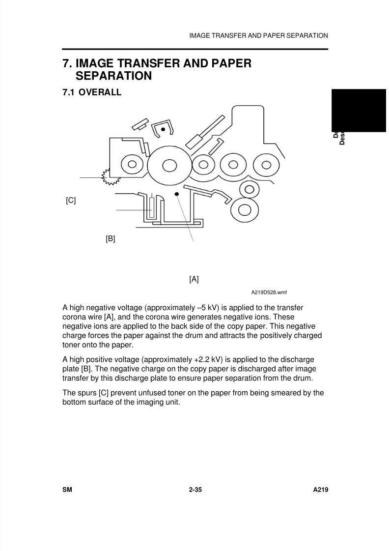
7/18/2019 A219 245 B019 4015 3813 Service
http://slidepdf.com/reader/full/a219-245-b019-4015-3813-service 78/372
7. IMAGE TRANSFER AND PAPERSEPARATION
7.1 OVERALL
A high negative voltage (approximately –5 kV) is applied to the transfercorona wire [A], and the corona wire generates negative ions. Thesenegative ions are applied to the back side of the copy paper. This negativecharge forces the paper against the drum and attracts the positively chargedtoner onto the paper.
A high positive voltage (approximately +2.2 kV) is applied to the dischargeplate [B]. The negative charge on the copy paper is discharged after imagetransfer by this discharge plate to ensure paper separation from the drum.
The spurs [C] prevent unfused toner on the paper from being smeared by thebottom surface of the imaging unit.
[A]
[B]
[C]
A219D528.wmf
D e t a i l e d
D e s c r i p t i o n s
IMAGE TRANSFER AND PAPER SEPARATION
SM 2-35 A219
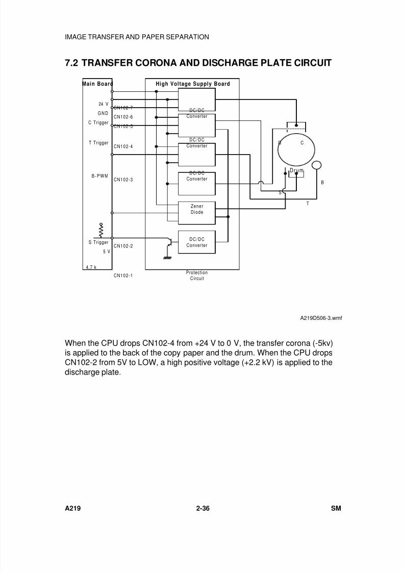
7/18/2019 A219 245 B019 4015 3813 Service
http://slidepdf.com/reader/full/a219-245-b019-4015-3813-service 79/372
7.2 TRANSFER CORONA AND DISCHARGE PLATE CIRCUIT
When the CPU drops CN102-4 from +24 V to 0 V, the transfer corona (-5kv)is applied to the back of the copy paper and the drum. When the CPU dropsCN102-2 from 5V to LOW, a high positive voltage (+2.2 kV) is applied to thedischarge plate.
DC/DCConverter
CN102-7
Drum
B
ZenerDiode
Protect ionCircuit
DC/DCConverter
DC/DCConverter
DC/DC
Converter
G N DCN102-6
CN102-4
CN102-3
CN102-2
CN102-1
24 V
C Trigger
T Trigger
B - P W M
S Trigger
S
T
G C
5 V
4.7 k
Main Board High Voltage Supply Board
CN102-5
A219D506-3.wmf
IMAGE TRANSFER AND PAPER SEPARATION
A219 2-36 SM

7/18/2019 A219 245 B019 4015 3813 Service
http://slidepdf.com/reader/full/a219-245-b019-4015-3813-service 80/372
8. DRUM CLEANING
8.1 OVERVIEW
A counter blade system is used for drum cleaning. The cleaning blade [A]scrapes off any toner remaining on the drum after the image is transferred tothe paper.
The removed toner is transported into the developer to be recycled.
[A]
A219D528-2.wmf
D e t a i l e d
D e s c r i p t i o n s
DRUM CLEANING
SM 2-37 A219
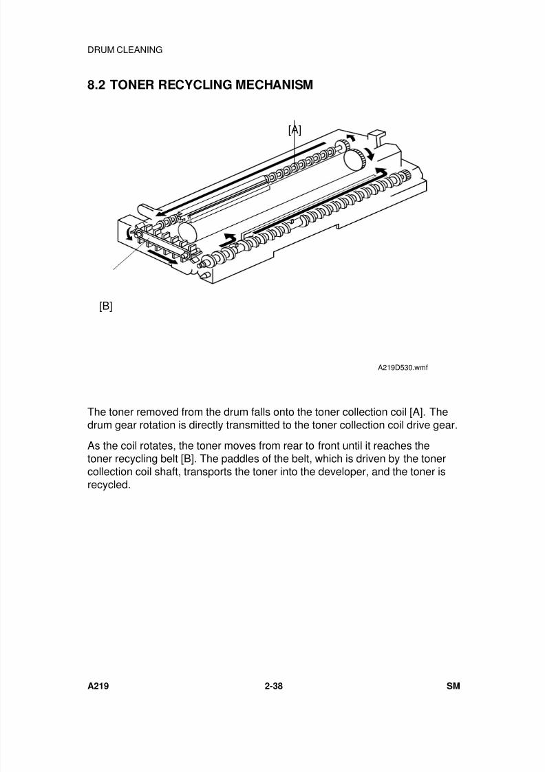
7/18/2019 A219 245 B019 4015 3813 Service
http://slidepdf.com/reader/full/a219-245-b019-4015-3813-service 81/372
8.2 TONER RECYCLING MECHANISM
The toner removed from the drum falls onto the toner collection coil [A]. Thedrum gear rotation is directly transmitted to the toner collection coil drive gear.
As the coil rotates, the toner moves from rear to front until it reaches thetoner recycling belt [B]. The paddles of the belt, which is driven by the tonercollection coil shaft, transports the toner into the developer, and the toner isrecycled.
[A]
[B]
A219D530.wmf
DRUM CLEANING
A219 2-38 SM
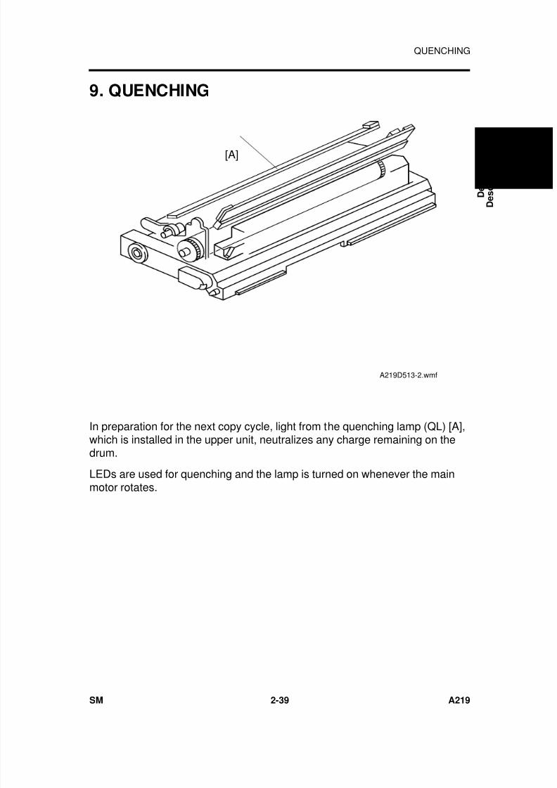
7/18/2019 A219 245 B019 4015 3813 Service
http://slidepdf.com/reader/full/a219-245-b019-4015-3813-service 82/372
9. QUENCHING
In preparation for the next copy cycle, light from the quenching lamp (QL) [A],which is installed in the upper unit, neutralizes any charge remaining on thedrum.
LEDs are used for quenching and the lamp is turned on whenever the mainmotor rotates.
[A]
A219D513-2.wmf
D e t a i l e d
D e s c r i p t i o n s
QUENCHING
SM 2-39 A219
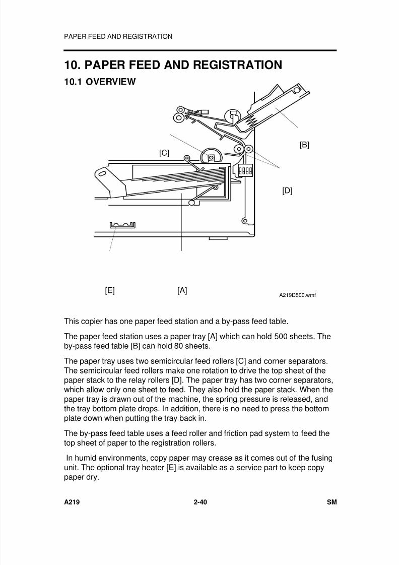
7/18/2019 A219 245 B019 4015 3813 Service
http://slidepdf.com/reader/full/a219-245-b019-4015-3813-service 83/372
10. PAPER FEED AND REGISTRATION
10.1 OVERVIEW
This copier has one paper feed station and a by-pass feed table.
The paper feed station uses a paper tray [A] which can hold 500 sheets. Theby-pass feed table [B] can hold 80 sheets.
The paper tray uses two semicircular feed rollers [C] and corner separators.The semicircular feed rollers make one rotation to drive the top sheet of thepaper stack to the relay rollers [D]. The paper tray has two corner separators,
which allow only one sheet to feed. They also hold the paper stack. When thepaper tray is drawn out of the machine, the spring pressure is released, andthe tray bottom plate drops. In addition, there is no need to press the bottomplate down when putting the tray back in.
The by-pass feed table uses a feed roller and friction pad system to feed thetop sheet of paper to the registration rollers.
In humid environments, copy paper may crease as it comes out of the fusingunit. The optional tray heater [E] is available as a service part to keep copypaper dry.
[A]
[B][C]
[D]
[E] A219D500.wmf
PAPER FEED AND REGISTRATION
A219 2-40 SM
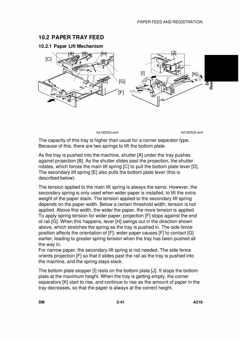
7/18/2019 A219 245 B019 4015 3813 Service
http://slidepdf.com/reader/full/a219-245-b019-4015-3813-service 84/372
10.2 PAPER TRAY FEED
10.2.1 Paper Lift Mechanism
The capacity of this tray is higher than usual for a corner separator type.Because of this, there are two springs to lift the bottom plate.
As the tray is pushed into the machine, shutter [A] under the tray pushesagainst projection [B]. As the shutter slides past the projection, the shutterrotates, which forces the main lift spring [C] to pull the bottom plate lever [D].The secondary lift spring [E] also pulls the bottom plate lever (this is
described below).The tension applied to the main lift spring is always the same. However, thesecondary spring is only used when wider paper is installed, to lift the extraweight of the paper stack. The tension applied to the secondary lift springdepends on the paper width. Below a certain threshold width, tension is notapplied. Above this width, the wider the paper, the more tension is applied.To apply spring tension for wider paper, projection [F] stops against the endof rail [G]. When this happens, lever [H] swings out in the direction shownabove, which stretches the spring as the tray is pushed in. The side fenceposition affects the orientation of [F]; wider paper causes [F] to contact [G]earlier, leading to greater spring tension when the tray has been pushed allthe way in.For narrow paper, the secondary lift spring is not needed. The side fenceorients projection [F] so that it slides past the rail as the tray is pushed intothe machine, and the spring stays slack.
The bottom plate stopper [I] rests on the bottom plate [J]. It stops the bottomplate at the maximum height. When the tray is getting empty, the cornerseparators [K] start to rise, and continue to rise as the amount of paper in thetray decreases, so that the paper is always at the correct height.
[A]
[C]
[B]
[G]
[F]
[D]
[E]
[H]
A219D534.wmf
[K]
[J]
[I]
A219D535.wmf
D e t a i l e d
D e s c r i p t i o n s
PAPER FEED AND REGISTRATION
SM 2-41 A219
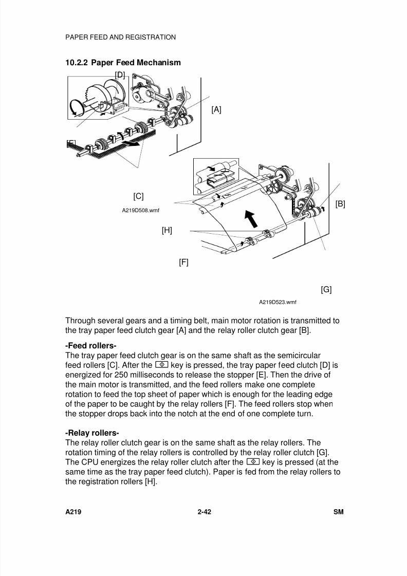
7/18/2019 A219 245 B019 4015 3813 Service
http://slidepdf.com/reader/full/a219-245-b019-4015-3813-service 85/372
10.2.2 Paper Feed Mechanism
Through several gears and a timing belt, main motor rotation is transmitted tothe tray paper feed clutch gear [A] and the relay roller clutch gear [B].
-Feed rollers-The tray paper feed clutch gear is on the same shaft as the semicircularfeed rollers [C]. After the key is pressed, the tray paper feed clutch [D] isenergized for 250 milliseconds to release the stopper [E]. Then the drive ofthe main motor is transmitted, and the feed rollers make one completerotation to feed the top sheet of paper which is enough for the leading edgeof the paper to be caught by the relay rollers [F]. The feed rollers stop whenthe stopper drops back into the notch at the end of one complete turn.
-Relay rollers-The relay roller clutch gear is on the same shaft as the relay rollers. Therotation timing of the relay rollers is controlled by the relay roller clutch [G].The CPU energizes the relay roller clutch after the key is pressed (at thesame time as the tray paper feed clutch). Paper is fed from the relay rollers tothe registration rollers [H].
[A]
[E]
[D]
[C]A219D508.wmf
[B]
[G]
[F]
[H]
A219D523.wmf
PAPER FEED AND REGISTRATION
A219 2-42 SM
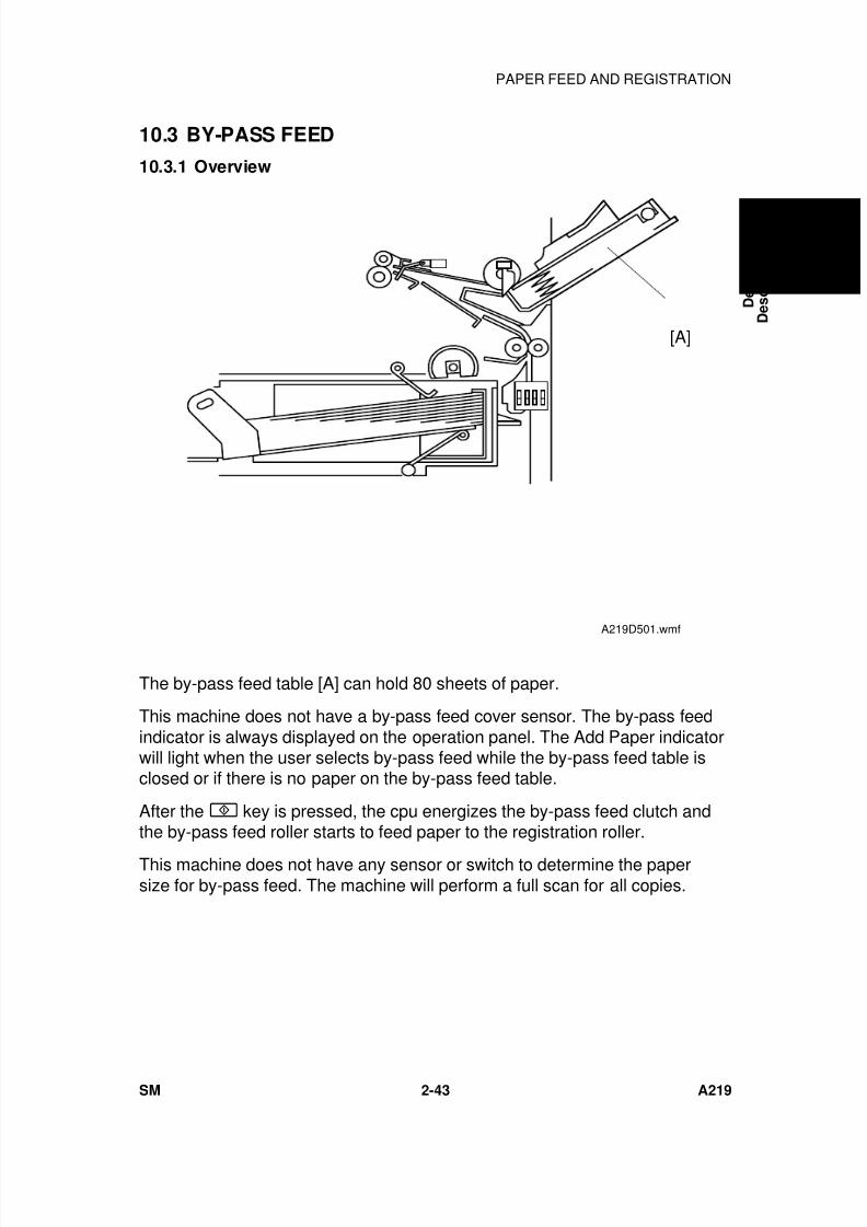
7/18/2019 A219 245 B019 4015 3813 Service
http://slidepdf.com/reader/full/a219-245-b019-4015-3813-service 86/372
10.3 BY-PASS FEED
10.3.1 Overview
The by-pass feed table [A] can hold 80 sheets of paper.
This machine does not have a by-pass feed cover sensor. The by-pass feedindicator is always displayed on the operation panel. The Add Paper indicatorwill light when the user selects by-pass feed while the by-pass feed table isclosed or if there is no paper on the by-pass feed table.
After the key is pressed, the cpu energizes the by-pass feed clutch andthe by-pass feed roller starts to feed paper to the registration roller.
This machine does not have any sensor or switch to determine the papersize for by-pass feed. The machine will perform a full scan for all copies.
[A]
A219D501.wmf
D e t a i l e d
D e s c r i p t i o n s
PAPER FEED AND REGISTRATION
SM 2-43 A219
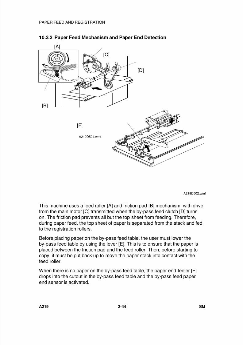
7/18/2019 A219 245 B019 4015 3813 Service
http://slidepdf.com/reader/full/a219-245-b019-4015-3813-service 87/372
10.3.2 Paper Feed Mechanism and Paper End Detection
This machine uses a feed roller [A] and friction pad [B] mechanism, with drivefrom the main motor [C] transmitted when the by-pass feed clutch [D] turnson. The friction pad prevents all but the top sheet from feeding. Therefore,during paper feed, the top sheet of paper is separated from the stack and fedto the registration rollers.
Before placing paper on the by-pass feed table, the user must lower theby-pass feed table by using the lever [E]. This is to ensure that the paper isplaced between the friction pad and the feed roller. Then, before starting tocopy, it must be put back up to move the paper stack into contact with thefeed roller.
When there is no paper on the by-pass feed table, the paper end feeler [F]drops into the cutout in the by-pass feed table and the by-pass feed paperend sensor is activated.
[E]
A219D502.wmf
[A]
[B]
[C]
[D]
[F]
A219D524.wmf
PAPER FEED AND REGISTRATION
A219 2-44 SM
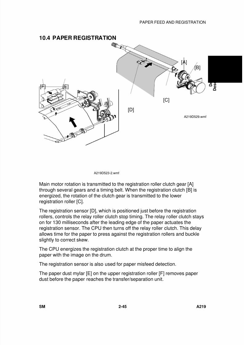
7/18/2019 A219 245 B019 4015 3813 Service
http://slidepdf.com/reader/full/a219-245-b019-4015-3813-service 88/372
10.4 PAPER REGISTRATION
Main motor rotation is transmitted to the registration roller clutch gear [A]through several gears and a timing belt. When the registration clutch [B] isenergized, the rotation of the clutch gear is transmitted to the lowerregistration roller [C].
The registration sensor [D], which is positioned just before the registrationrollers, controls the relay roller clutch stop timing. The relay roller clutch stayson for 130 milliseconds after the leading edge of the paper actuates theregistration sensor. The CPU then turns off the relay roller clutch. This delayallows time for the paper to press against the registration rollers and buckle
slightly to correct skew.The CPU energizes the registration clutch at the proper time to align thepaper with the image on the drum.
The registration sensor is also used for paper misfeed detection.
The paper dust mylar [E] on the upper registration roller [F] removes paperdust before the paper reaches the transfer/separation unit.
[A][B]
[C]
[D]A219D529.wmf
[E][F]
A219D523-2.wmf
D e t a i l e d
D e s c r i p t i o n s
PAPER FEED AND REGISTRATION
SM 2-45 A219
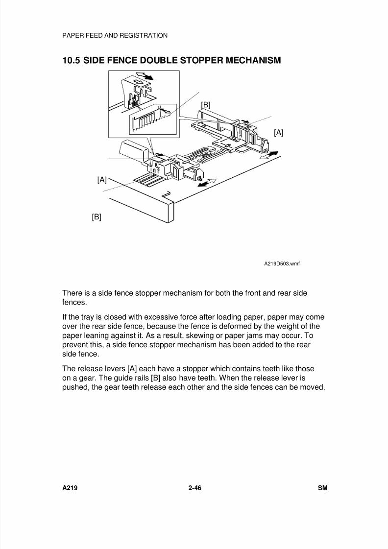
7/18/2019 A219 245 B019 4015 3813 Service
http://slidepdf.com/reader/full/a219-245-b019-4015-3813-service 89/372
10.5 SIDE FENCE DOUBLE STOPPER MECHANISM
There is a side fence stopper mechanism for both the front and rear sidefences.
If the tray is closed with excessive force after loading paper, paper may comeover the rear side fence, because the fence is deformed by the weight of thepaper leaning against it. As a result, skewing or paper jams may occur. Toprevent this, a side fence stopper mechanism has been added to the rearside fence.
The release levers [A] each have a stopper which contains teeth like those
on a gear. The guide rails [B] also have teeth. When the release lever ispushed, the gear teeth release each other and the side fences can be moved.
[B]
[A]
[A]
[B]
A219D503.wmf
PAPER FEED AND REGISTRATION
A219 2-46 SM
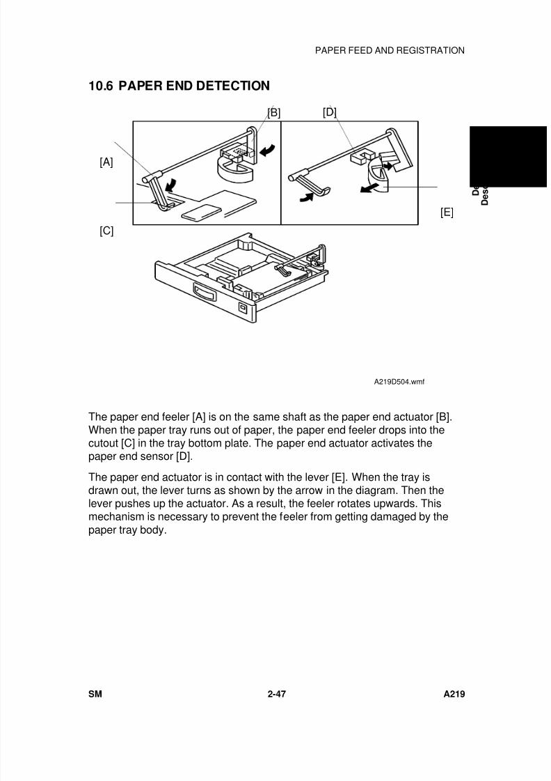
7/18/2019 A219 245 B019 4015 3813 Service
http://slidepdf.com/reader/full/a219-245-b019-4015-3813-service 90/372
10.6 PAPER END DETECTION
The paper end feeler [A] is on the same shaft as the paper end actuator [B].When the paper tray runs out of paper, the paper end feeler drops into thecutout [C] in the tray bottom plate. The paper end actuator activates thepaper end sensor [D].
The paper end actuator is in contact with the lever [E]. When the tray isdrawn out, the lever turns as shown by the arrow in the diagram. Then thelever pushes up the actuator. As a result, the feeler rotates upwards. Thismechanism is necessary to prevent the feeler from getting damaged by thepaper tray body.
[D][B]
[E]
[C]
[A]
A219D504.wmf
D e t a i l e d
D e s c r i p t i o n s
PAPER FEED AND REGISTRATION
SM 2-47 A219
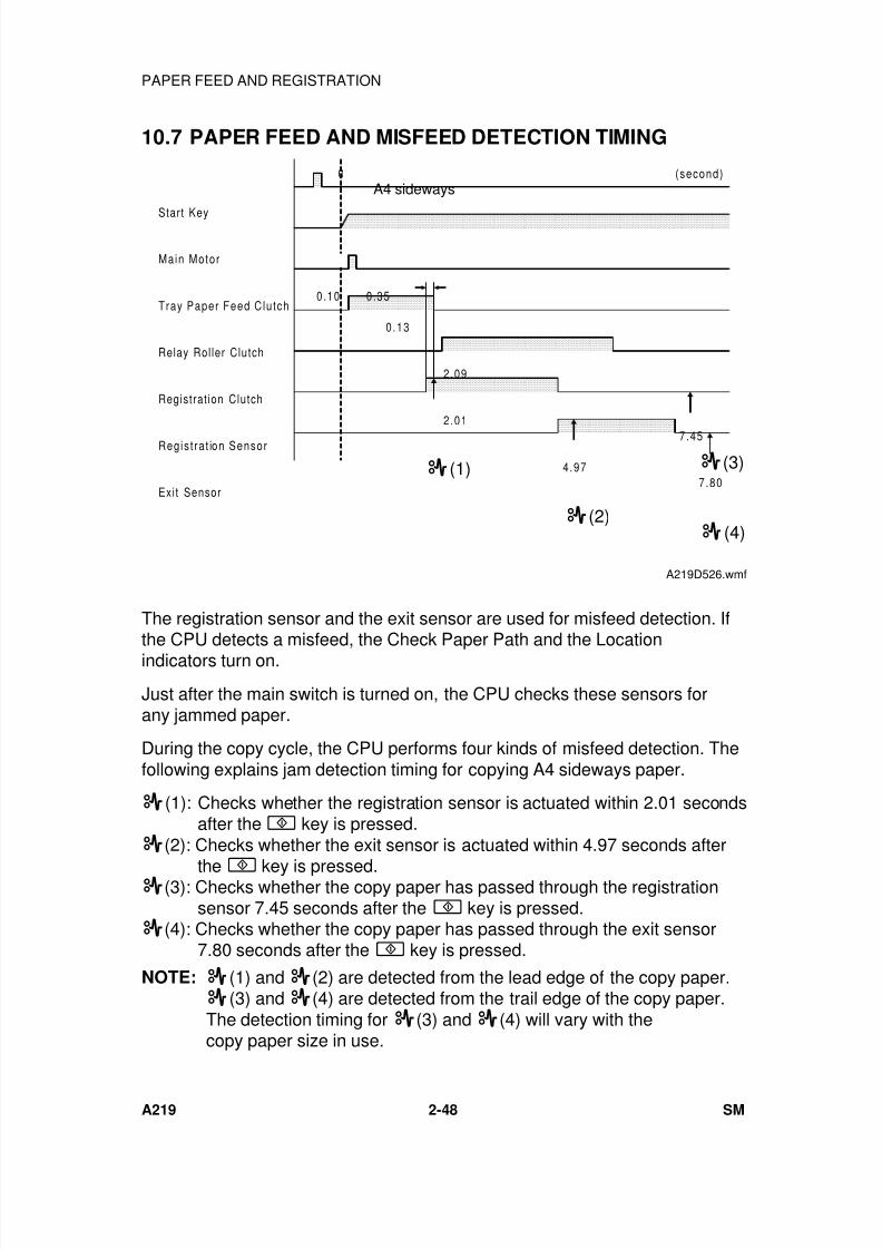
7/18/2019 A219 245 B019 4015 3813 Service
http://slidepdf.com/reader/full/a219-245-b019-4015-3813-service 91/372
10.7 PAPER FEED AND MISFEED DETECTION TIMING
The registration sensor and the exit sensor are used for misfeed detection. Ifthe CPU detects a misfeed, the Check Paper Path and the Locationindicators turn on.
Just after the main switch is turned on, the CPU checks these sensors forany jammed paper.
During the copy cycle, the CPU performs four kinds of misfeed detection. Thefollowing explains jam detection timing for copying A4 sideways paper.
(1): Checks whether the registration sensor is actuated within 2.01 secondsafter the key is pressed.
(2): Checks whether the exit sensor is actuated within 4.97 seconds after
the key is pressed. (3): Checks whether the copy paper has passed through the registrationsensor 7.45 seconds after the key is pressed.
(4): Checks whether the copy paper has passed through the exit sensor7.80 seconds after the key is pressed.
NOTE: (1) and (2) are detected from the lead edge of the copy paper. (3) and (4) are detected from the trail edge of the copy paper.The detection timing for (3) and (4) will vary with thecopy paper size in use.
Start Key
Main Motor
Tray Paper Feed Clutch
Relay Rol ler Clutch
Registrat ion Clutch
Regist rat ion Sensor
Exi t Sensor
0
0.10 0.35
0.13
2.09
2.01
4.97
7.45
7.80
(second)
(3)
(4)
(1)
(2)
A4 sideways
A219D526.wmf
PAPER FEED AND REGISTRATION
A219 2-48 SM
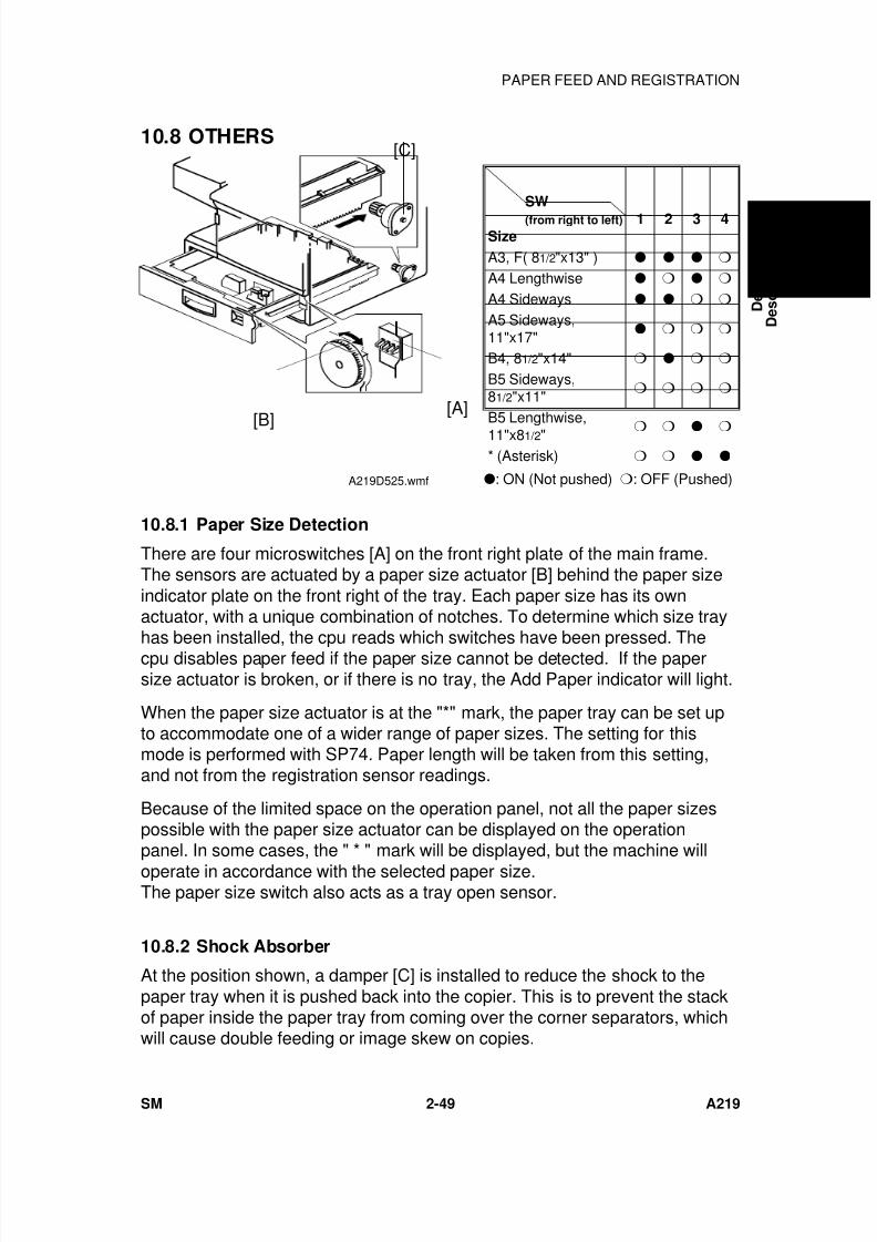
7/18/2019 A219 245 B019 4015 3813 Service
http://slidepdf.com/reader/full/a219-245-b019-4015-3813-service 92/372
10.8 OTHERS
SW
(from right to left)
Size1 2 3 4
A3, F( 81/2"x13" )
A4 Lengthwise
A4 Sideways
A5 Sideways,11"x17"
B4, 81/2"x14"
B5 Sideways,81/2"x11"
B5 Lengthwise,
11"x81/2"
* (Asterisk)
: ON (Not pushed) : OFF (Pushed)
10.8.1 Paper Size Detection
There are four microswitches [A] on the front right plate of the main frame.The sensors are actuated by a paper size actuator [B] behind the paper sizeindicator plate on the front right of the tray. Each paper size has its ownactuator, with a unique combination of notches. To determine which size tray
has been installed, the cpu reads which switches have been pressed. Thecpu disables paper feed if the paper size cannot be detected. If the papersize actuator is broken, or if there is no tray, the Add Paper indicator will light.
When the paper size actuator is at the "*" mark, the paper tray can be set upto accommodate one of a wider range of paper sizes. The setting for thismode is performed with SP74. Paper length will be taken from this setting,and not from the registration sensor readings.
Because of the limited space on the operation panel, not all the paper sizespossible with the paper size actuator can be displayed on the operationpanel. In some cases, the " * " mark will be displayed, but the machine willoperate in accordance with the selected paper size.The paper size switch also acts as a tray open sensor.
10.8.2 Shock Absorber
At the position shown, a damper [C] is installed to reduce the shock to thepaper tray when it is pushed back into the copier. This is to prevent the stackof paper inside the paper tray from coming over the corner separators, whichwill cause double feeding or image skew on copies.
[C]
[B][A]
A219D525.wmf
D e t a i l e d
D e s c r i p t i o n s
PAPER FEED AND REGISTRATION
SM 2-49 A219
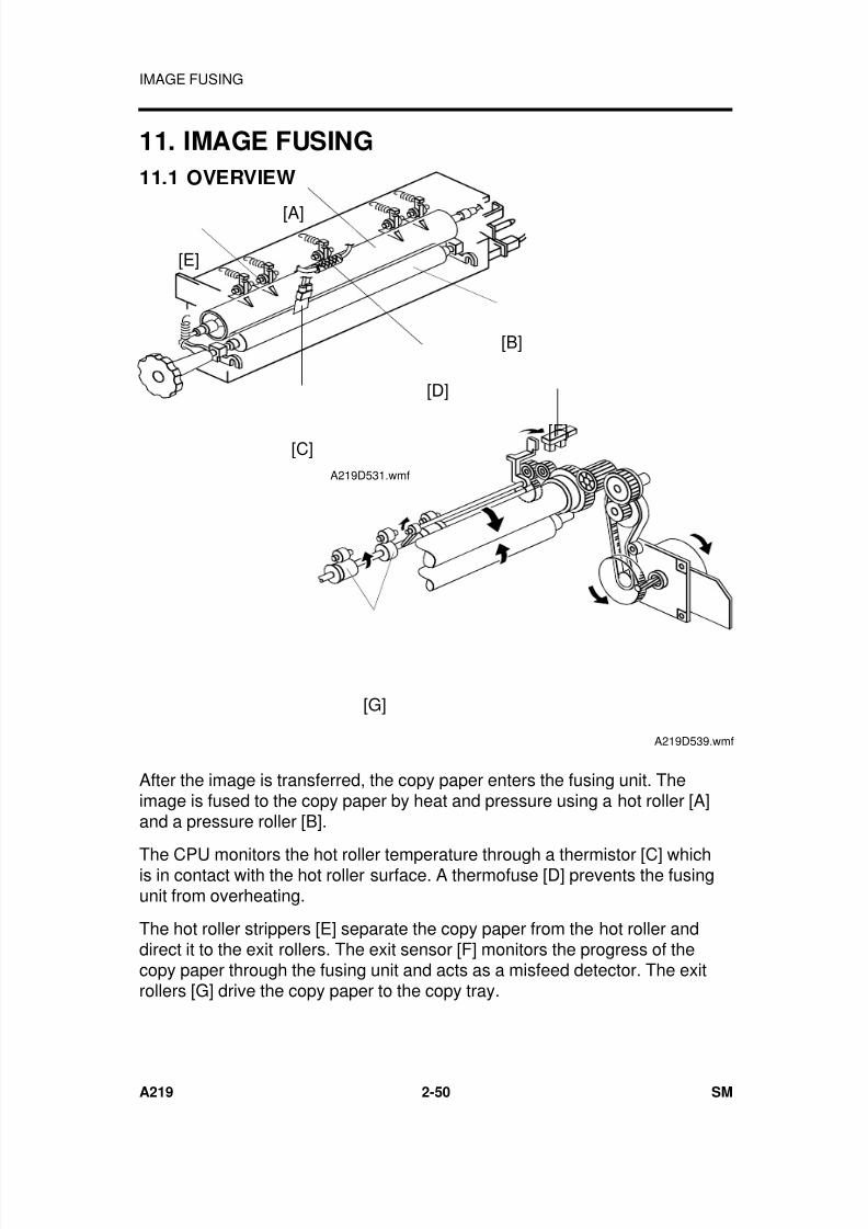
7/18/2019 A219 245 B019 4015 3813 Service
http://slidepdf.com/reader/full/a219-245-b019-4015-3813-service 93/372
11. IMAGE FUSING
11.1 OVERVIEW
After the image is transferred, the copy paper enters the fusing unit. Theimage is fused to the copy paper by heat and pressure using a hot roller [A]and a pressure roller [B].
The CPU monitors the hot roller temperature through a thermistor [C] whichis in contact with the hot roller surface. A thermofuse [D] prevents the fusingunit from overheating.
The hot roller strippers [E] separate the copy paper from the hot roller anddirect it to the exit rollers. The exit sensor [F] monitors the progress of thecopy paper through the fusing unit and acts as a misfeed detector. The exitrollers [G] drive the copy paper to the copy tray.
[A]
[E]
[B]
[D]
[C]A219D531.wmf
[F]
[G]
A219D539.wmf
IMAGE FUSING
A219 2-50 SM
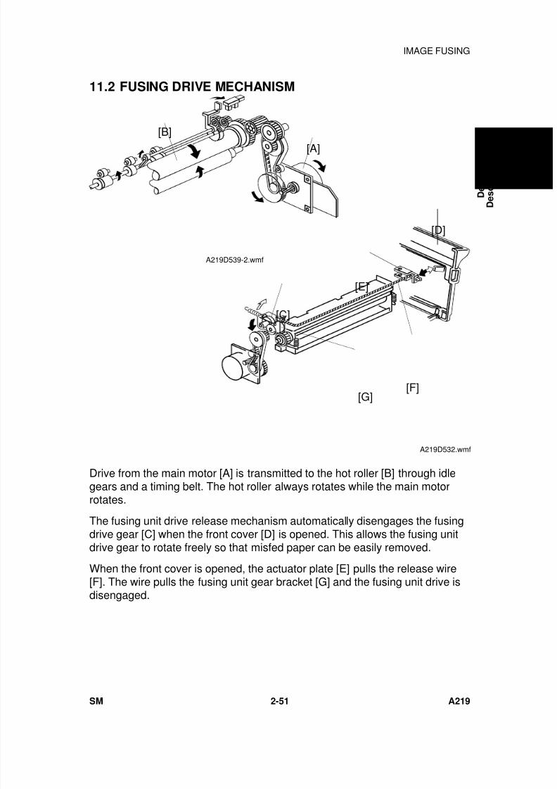
7/18/2019 A219 245 B019 4015 3813 Service
http://slidepdf.com/reader/full/a219-245-b019-4015-3813-service 94/372
11.2 FUSING DRIVE MECHANISM
Drive from the main motor [A] is transmitted to the hot roller [B] through idlegears and a timing belt. The hot roller always rotates while the main motorrotates.
The fusing unit drive release mechanism automatically disengages the fusingdrive gear [C] when the front cover [D] is opened. This allows the fusing unit
drive gear to rotate freely so that misfed paper can be easily removed.When the front cover is opened, the actuator plate [E] pulls the release wire[F]. The wire pulls the fusing unit gear bracket [G] and the fusing unit drive isdisengaged.
[C]
[G][F]
[E]
[D]
A219D532.wmf
[A][B]
A219D539-2.wmf
D e t a i l e d
D e s c r i p t i o n s
IMAGE FUSING
SM 2-51 A219
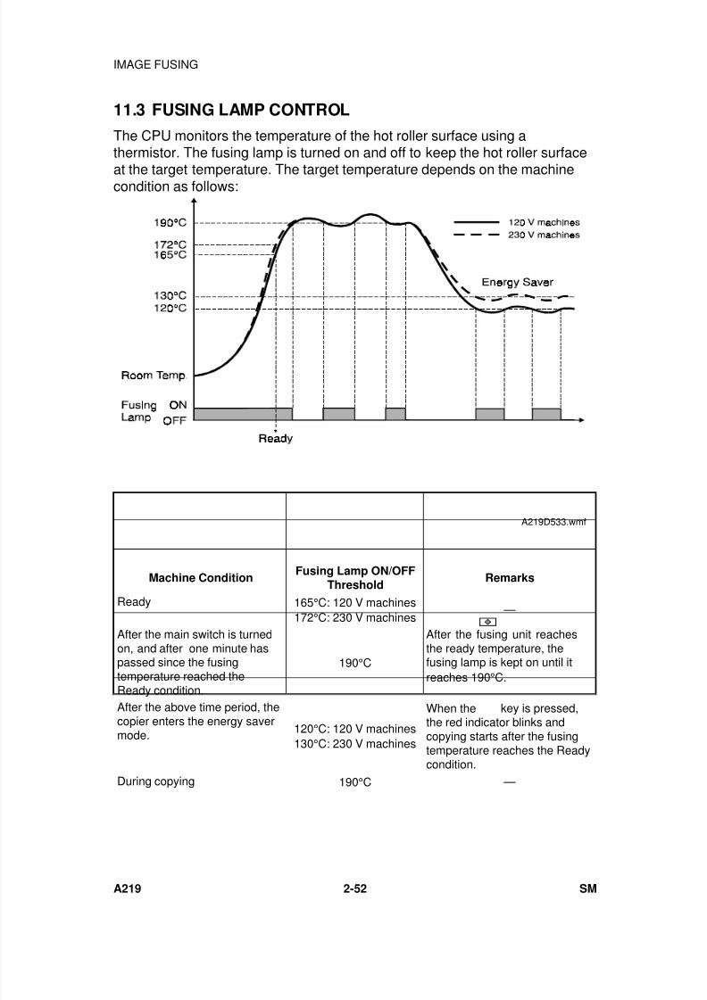
7/18/2019 A219 245 B019 4015 3813 Service
http://slidepdf.com/reader/full/a219-245-b019-4015-3813-service 95/372
11.3 FUSING LAMP CONTROL
The CPU monitors the temperature of the hot roller surface using athermistor. The fusing lamp is turned on and off to keep the hot roller surface
at the target temperature. The target temperature depends on the machinecondition as follows:
Machine ConditionFusing Lamp ON/OFF
ThresholdRemarks
Ready 165°C: 120 V machines172°C: 230 V machines
—
After the main switch is turnedon, and after one minute haspassed since the fusingtemperature reached the
Ready condition.
190°C
After the fusing unit reachesthe ready temperature, thefusing lamp is kept on until itreaches 190°C.
After the above time period, thecopier enters the energy savermode. 120°C: 120 V machines
130°C: 230 V machines
When the
key is pressed,the red indicator blinks andcopying starts after the fusingtemperature reaches the Readycondition.
During copying 190°C —
A219D533.wmf
IMAGE FUSING
A219 2-52 SM

7/18/2019 A219 245 B019 4015 3813 Service
http://slidepdf.com/reader/full/a219-245-b019-4015-3813-service 96/372
When the main switch is turned on, the CPU turns on the fusing lamp. Whenthe fusing thermistor detects the ready temperature, the machine enters theready condition. After the ready temperature is detected, the CPU keeps thefusing temperature at 190°C for one minute, then the target temperature is
changed to 120°C (120 V machines) or 130°C (230 V machines).
When the key is pressed, if the fusing lamp temperature is higher thanthe ready temperature, the machine starts copying immediately. If thetemperature is lower, the fusing lamp is turned on and the start indicator turnsred and blinks. Copying starts after the fusing temperature reaches the readytemperature, and the fusing temperature is kept at 190°C during copying.
After copying is finished, the fusing temperature is kept at 190°C for oneminute.
To prevent any copy quality problem caused by exposure lamp intensityfluctuation, the fusing lamp does not turn on while the exposure lamp is on,even if the fusing temperature drops below 190°C.
D e t a i l e d
D e s c r i p t i o n s
IMAGE FUSING
SM 2-53 A219
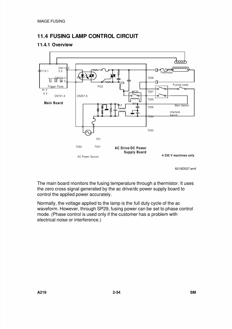
7/18/2019 A219 245 B019 4015 3813 Service
http://slidepdf.com/reader/full/a219-245-b019-4015-3813-service 97/372
11.4 FUSING LAMP CONTROL CIRCUIT
11.4.1 Overview
The main board monitors the fusing temperature through a thermistor. It usesthe zero cross signal generated by the ac drive/dc power supply board tocontrol the applied power accurately.
Normally, the voltage applied to the lamp is the full duty cycle of the acwaveform. However, through SP29, fusing power can be set to phase controlmode. (Phase control is used only if the customer has a problem withelectrical noise or interference.)
CN113-1CN113-25 V
CN101-3
24 V
CN101-4
CN207-7
CN207-6
PC2
T205
T206
T204
T207
T208
T203
Interlock
Switch
Main Switch
Fus ing Lamp
Fusing
Thermistor
AC Power Source
FU 1
AC Drive/DC PowerSupply Board
Main Board
Trigger Pulse
24 V
0 V
T202 T201
RY1L4
C20
230 V machines only
A219D537.wmf
IMAGE FUSING
A219 2-54 SM
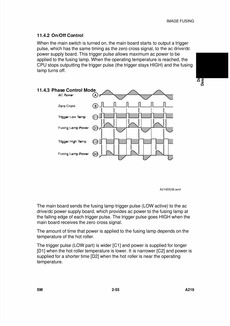
7/18/2019 A219 245 B019 4015 3813 Service
http://slidepdf.com/reader/full/a219-245-b019-4015-3813-service 98/372
11.4.2 On/Off Control
When the main switch is turned on, the main board starts to output a triggerpulse, which has the same timing as the zero cross signal, to the ac drive/dcpower supply board. This trigger pulse allows maximum ac power to beapplied to the fusing lamp. When the operating temperature is reached, theCPU stops outputting the trigger pulse (the trigger stays HIGH) and the fusinglamp turns off.
11.4.3 Phase Control Mode
The main board sends the fusing lamp trigger pulse (LOW active) to the acdrive/dc power supply board, which provides ac power to the fusing lamp atthe falling edge of each trigger pulse. The trigger pulse goes HIGH when themain board receives the zero cross signal.
The amount of time that power is applied to the fusing lamp depends on thetemperature of the hot roller.
The trigger pulse (LOW part) is wider [C1] and power is supplied for longer[D1] when the hot roller temperature is lower. It is narrower [C2] and power issupplied for a shorter time [D2] when the hot roller is near the operatingtemperature.
A219D538.wmf
D e t a i l e d
D e s c r i p t i o n s
IMAGE FUSING
SM 2-55 A219

7/18/2019 A219 245 B019 4015 3813 Service
http://slidepdf.com/reader/full/a219-245-b019-4015-3813-service 99/372
11.4.4 Overheat Protection
There is an overheat protection circuit in the main board. If the hot rollertemperature reaches 245°C during the main motor off condition, or 255°C
during the main motor on condition, the resistance of the thermistor (betweenCN113-1 and CN113-2) becomes too low. If the main board detects thiscondition, "E-53" lights on the operation panel and power to the fusing lampis cut.
Even if the thermistor overheat protection fails, the thermofuse opens when itreaches 169°C, removing power from the fusing lamp.
IMAGE FUSING
A219 2-56 SM

7/18/2019 A219 245 B019 4015 3813 Service
http://slidepdf.com/reader/full/a219-245-b019-4015-3813-service 100/372
INSTALLATION

7/18/2019 A219 245 B019 4015 3813 Service
http://slidepdf.com/reader/full/a219-245-b019-4015-3813-service 101/372
7/18/2019 A219 245 B019 4015 3813 Service
http://slidepdf.com/reader/full/a219-245-b019-4015-3813-service 102/372
1. INSTALLATION REQUIREMENTS
1.1 ENVIRONMENT
1. Temperature Range: 10°C to 30°C (50°F to 87°F) 2. Humidity Range: 15% to 90% RH
3. Ambient Illumination: Less than 1,500 lux (Do not exposure to directsunlight.)
4. Ventilation: Room air should turn over at least 3 times perhour
5. Ambient Dust: Less than 0.15 mg/m3 (4 x 10⁻³ oz/yd3)
6. If the place of installation is air-conditioned or heated, do not place themachine:1) Where it will not be subjected to sudden temperature changes.
2) Where it will not be directly exposed to cool air from an air-conditioner.
3) Where it will not be directly exposed to heat from a heater.
7. Do not place the machine where it will be exposed to corrosive gasses.
8. Do not install the machine at any location over 2,000 m (6,500 feet)
above sea level. 9. Place the copier on a strong and level base.
10. Do not place the machine where it may be subjected to strong vibrations.
1.2 MACHINE LEVEL
1. Front to back: Within 5 mm (0.2") of level
2. Right to left: Within 5 mm (0.2") of level
I n
s t a l l a t i o n
INSTALLATION REQUIREMENTS
SM 3-1 A219
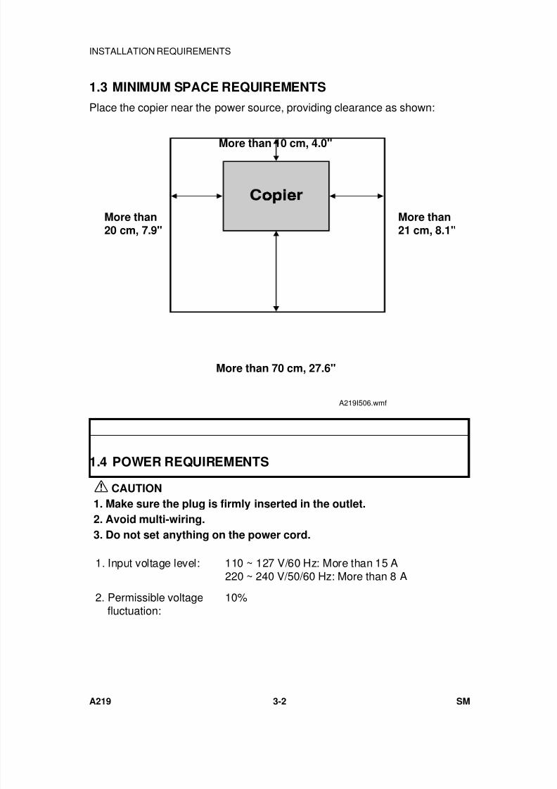
7/18/2019 A219 245 B019 4015 3813 Service
http://slidepdf.com/reader/full/a219-245-b019-4015-3813-service 103/372
1.3 MINIMUM SPACE REQUIREMENTS
Place the copier near the power source, providing clearance as shown:
1.4 POWER REQUIREMENTS
CAUTION
1. Make sure the plug is firmly inserted in the outlet.
2. Avoid multi-wiring.
3. Do not set anything on the power cord.
1. Input voltage level: 110 ~ 127 V/60 Hz: More than 15 A220 ~ 240 V/50/60 Hz: More than 8 A
2. Permissible voltagefluctuation:
10%
More than 10 cm, 4.0"
More than 70 cm, 27.6"
More than20 cm, 7.9"
More than21 cm, 8.1"
A219I506.wmf
INSTALLATION REQUIREMENTS
A219 3-2 SM
7/18/2019 A219 245 B019 4015 3813 Service
http://slidepdf.com/reader/full/a219-245-b019-4015-3813-service 104/372
2. COPIER (A219)
2.1 ACCESSORY CHECK
Check the quantity and condition of the accessories in the box against thefollowing list:
1. Model Name Decal (-10, -22 machines)
2. Symbol Explanation Decal - Multi-language
3. Installation Procedure - Multi-language (-10, -15, -22, -26 machines)
4. Operation Instructions - English (-10, -15, -17, -19, -22, -26, -29machines)
5. NECR - English (-17 machines)
6. NECR - Multi-language (-27, -29 machines)
7. Copy Tray
8. User Survey Card (-17 machines)
9. Envelope for NECR (-17 machines)
I n
s t a l l a t i o n
COPIER (A219)
SM 3-3 A219
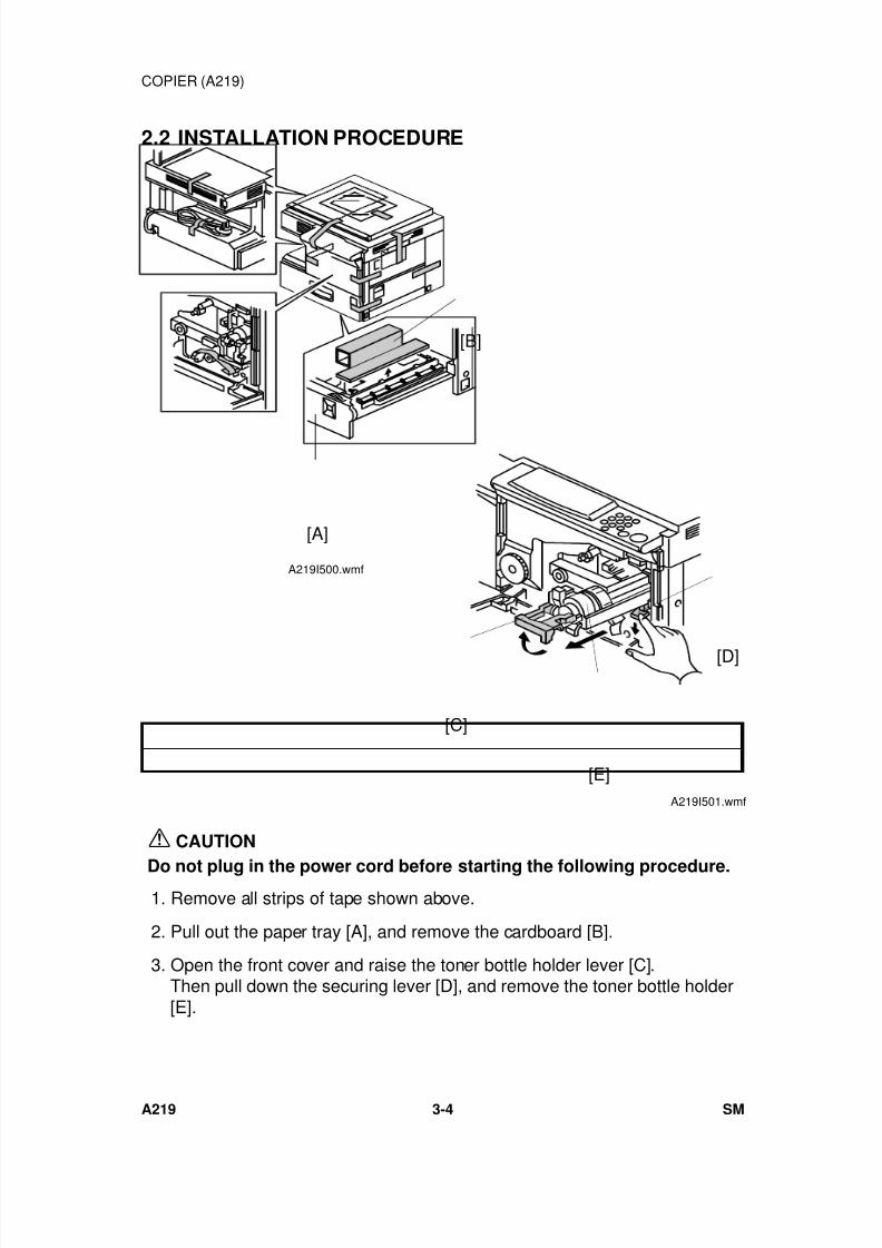
7/18/2019 A219 245 B019 4015 3813 Service
http://slidepdf.com/reader/full/a219-245-b019-4015-3813-service 105/372
2.2 INSTALLATION PROCEDURE
CAUTION
Do not plug in the power cord before starting the following procedure.
1. Remove all strips of tape shown above.
2. Pull out the paper tray [A], and remove the cardboard [B].
3. Open the front cover and raise the toner bottle holder lever [C].Then pull down the securing lever [D], and remove the toner bottle holder[E].
[B]
[A]
A219I500.wmf
[D]
[C]
[E]A219I501.wmf
COPIER (A219)
A219 3-4 SM
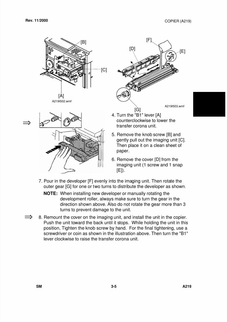
7/18/2019 A219 245 B019 4015 3813 Service
http://slidepdf.com/reader/full/a219-245-b019-4015-3813-service 106/372
4. Turn the "B1" lever [A]counterclockwise to lower thetransfer corona unit.
5. Remove the knob screw [B] andgently pull out the imaging unit [C].Then place it on a clean sheet ofpaper.
6. Remove the cover [D] from theimaging unit (1 screw and 1 snap[E]).
7. Pour in the developer [F] evenly into the imaging unit. Then rotate theouter gear [G] for one or two turns to distribute the developer as shown.
NOTE: When installing new developer or manually rotating thedevelopment roller, always make sure to turn the gear in thedirection shown above. Also do not rotate the gear more than 3turns to prevent damage to the unit.
8. Remount the cover on the imaging unit, and install the unit in the copier.
Push the unit toward the back until it stops. While holding the unit in thisposition, Tighten the knob screw by hand. For the final tightening, use ascrewdriver or coin as shown in the illustration above. Then turn the "B1"
lever clockwise to raise the transfer corona unit.
Rev. 11/2000
⇒
⇒
[B]
[C]
[A]A219I502.wmf
[F]
[E][D]
[G]
A219I503.wmf
I n
s t a l l a t i o n
COPIER (A219)
SM 3-5 A219
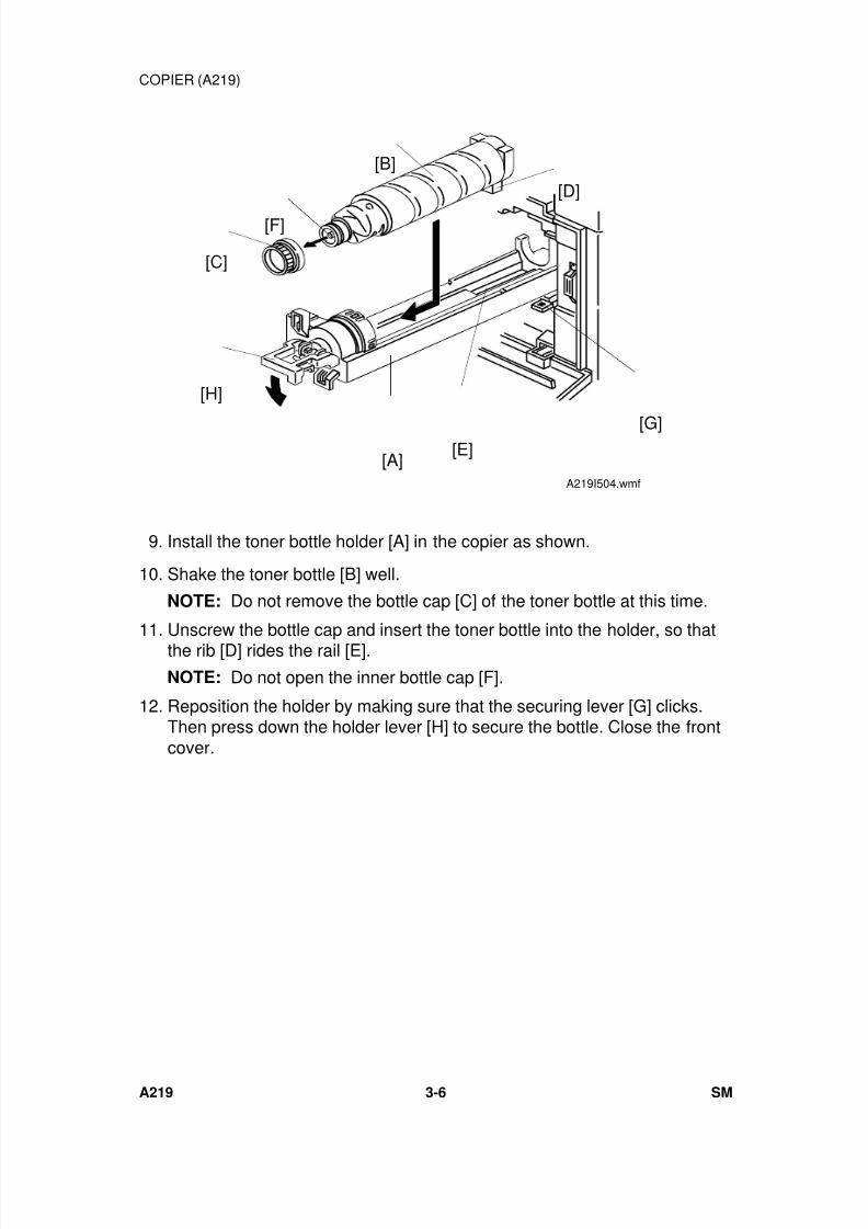
7/18/2019 A219 245 B019 4015 3813 Service
http://slidepdf.com/reader/full/a219-245-b019-4015-3813-service 107/372
9. Install the toner bottle holder [A] in the copier as shown.
10. Shake the toner bottle [B] well.
NOTE: Do not remove the bottle cap [C] of the toner bottle at this time.
11. Unscrew the bottle cap and insert the toner bottle into the holder, so thatthe rib [D] rides the rail [E].
NOTE: Do not open the inner bottle cap [F].
12. Reposition the holder by making sure that the securing lever [G] clicks.Then press down the holder lever [H] to secure the bottle. Close the frontcover.
[B]
[F]
[C]
[H]
[A]
[D]
[G][E]
A219I504.wmf
COPIER (A219)
A219 3-6 SM
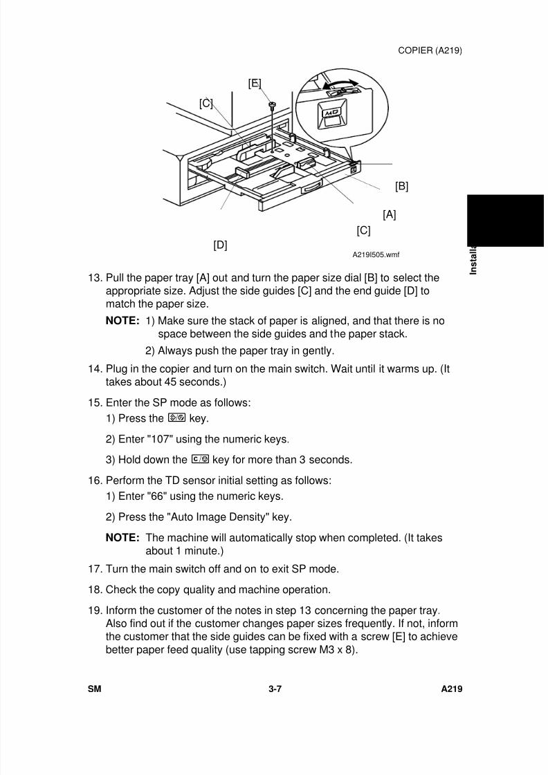
7/18/2019 A219 245 B019 4015 3813 Service
http://slidepdf.com/reader/full/a219-245-b019-4015-3813-service 108/372
13. Pull the paper tray [A] out and turn the paper size dial [B] to select theappropriate size. Adjust the side guides [C] and the end guide [D] tomatch the paper size.
NOTE: 1) Make sure the stack of paper is aligned, and that there is nospace between the side guides and the paper stack.
2) Always push the paper tray in gently.
14. Plug in the copier and turn on the main switch. Wait until it warms up. (Ittakes about 45 seconds.)
15. Enter the SP mode as follows:1) Press the key.
2) Enter "107" using the numeric keys.
3) Hold down the key for more than 3 seconds.
16. Perform the TD sensor initial setting as follows:1) Enter "66" using the numeric keys.
2) Press the "Auto Image Density" key.
NOTE: The machine will automatically stop when completed. (It takesabout 1 minute.)
17. Turn the main switch off and on to exit SP mode.
18. Check the copy quality and machine operation.
19. Inform the customer of the notes in step 13 concerning the paper tray.Also find out if the customer changes paper sizes frequently. If not, informthe customer that the side guides can be fixed with a screw [E] to achievebetter paper feed quality (use tapping screw M3 x 8).
[D]
[C]
[B]
[A]
[E]
[C]
A219I505.wmf
I n
s t a l l a t i o n
COPIER (A219)
SM 3-7 A219

7/18/2019 A219 245 B019 4015 3813 Service
http://slidepdf.com/reader/full/a219-245-b019-4015-3813-service 109/372
3. DOCUMENT FEEDER (A662)
3.1 ACCESSORY CHECK
Check the accessories against the following list:Description Q’ty
1. Voltage Reference Decal.................................................. 1
2. Thumb Screw M4 x 12...................................................... 2
3. Stud Screw (M3)............................................................... 2
4. Installation Procedure - English........................................ 1
5. NECR - Multi-language..................................................... 1
6. Interface Unit for A219 copier .......................................... 1
7. Accessory Kit for A203 copier .......................................... 1• Interface Unit Bracket.................................................. 1
• Stud Screw (M4).......................................................... 2
• Harness Clamp ........................................................... 1
• Upper Unit Stand......................................................... 1
• Stepped Screw (Short) ................................................ 1
• Stepped Screw (Long)................................................. 1• Magnet......................................................................... 1
• Operation Decal .......................................................... 1
• Screw Driver................................................................ 1
DOCUMENT FEEDER (A662)
A219 3-8 SM
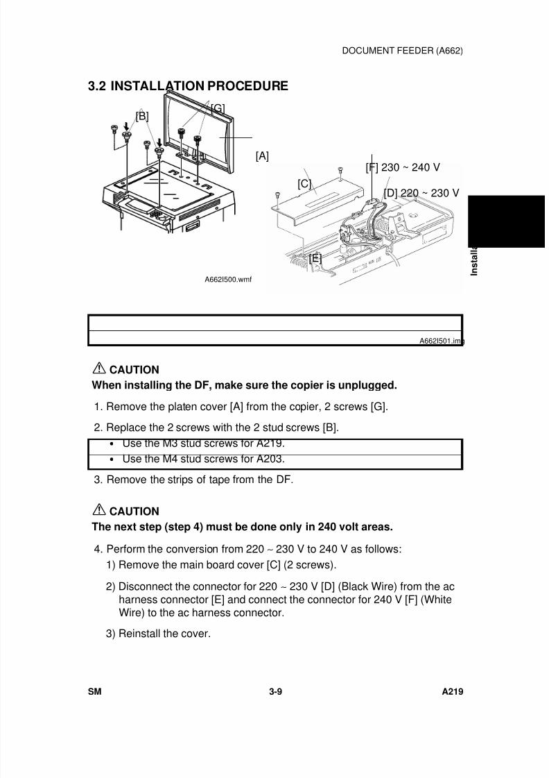
7/18/2019 A219 245 B019 4015 3813 Service
http://slidepdf.com/reader/full/a219-245-b019-4015-3813-service 110/372
3.2 INSTALLATION PROCEDURE
CAUTION
When installing the DF, make sure the copier is unplugged.
1. Remove the platen cover [A] from the copier, 2 screws [G]. 2. Replace the 2 screws with the 2 stud screws [B].
• Use the M3 stud screws for A219.• Use the M4 stud screws for A203.
3. Remove the strips of tape from the DF.
CAUTION
The next step (step 4) must be done only in 240 volt areas.
4. Perform the conversion from 220 ∼ 230 V to 240 V as follows:1) Remove the main board cover [C] (2 screws).
2) Disconnect the connector for 220 ∼ 230 V [D] (Black Wire) from the acharness connector [E] and connect the connector for 240 V [F] (WhiteWire) to the ac harness connector.
3) Reinstall the cover.
[A]
[B][G]
A662I500.wmf
[F] 230 ~ 240 V
[D] 220 ~ 230 V[C]
[E]
A662I501.img
I n
s t a l l a t i o n
DOCUMENT FEEDER (A662)
SM 3-9 A219
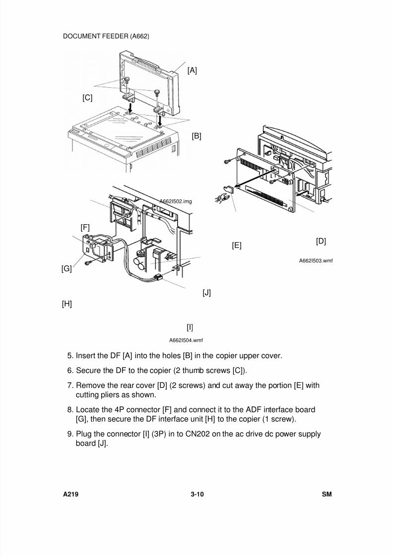
7/18/2019 A219 245 B019 4015 3813 Service
http://slidepdf.com/reader/full/a219-245-b019-4015-3813-service 111/372
5. Insert the DF [A] into the holes [B] in the copier upper cover.
6. Secure the DF to the copier (2 thumb screws [C]).
7. Remove the rear cover [D] (2 screws) and cut away the portion [E] withcutting pliers as shown.
8. Locate the 4P connector [F] and connect it to the ADF interface board[G], then secure the DF interface unit [H] to the copier (1 screw).
9. Plug the connector [I] (3P) in to CN202 on the ac drive dc power supplyboard [J].
[A]
[C]
[B]
A662I502.img
[D][E]
A662I503.wmf
[F]
[G]
[J]
[I]
[H]
A662I504.wmf
DOCUMENT FEEDER (A662)
A219 3-10 SM
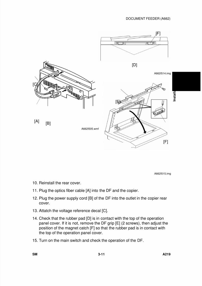
7/18/2019 A219 245 B019 4015 3813 Service
http://slidepdf.com/reader/full/a219-245-b019-4015-3813-service 112/372
10. Reinstall the rear cover.
11. Plug the optics fiber cable [A] into the DF and the copier.
12. Plug the power supply cord [B] of the DF into the outlet in the copier rearcover.
13. Attatch the voltage reference decal [C].
14. Check that the rubber pad [D] is in contact with the top of the operationpanel cover. If it is not, remove the DF grip [E] (2 screws), then adjust theposition of the magnet catch [F] so that the rubber pad is in contact withthe top of the operation panel cover.
15. Turn on the main switch and check the operation of the DF.
[B][A]
[C]
A662I505.wmf
[D]
[F]
A662I514.img
[E]
[F]
A662I515.img
I n
s t a l l a t i o n
DOCUMENT FEEDER (A662)
SM 3-11 A219

7/18/2019 A219 245 B019 4015 3813 Service
http://slidepdf.com/reader/full/a219-245-b019-4015-3813-service 113/372
4. SORTER (A657)
4.1 ACCESSORY CHECK
Check the accessories against the following list:Description Q’ty
1. Holder Bracket.................................................................. 1
2. Magnet Catch ................................................................... 1
3. Tapping Screw M4 x 6...................................................... 6
4. Grounding Screw M4 x 8 .................................................. 1
5. Snap Ring ......................................................................... 1
6. NECR - Multi-language..................................................... 1
7. Installation Procedure - English........................................ 1
SORTER (A657)
A219 3-12 SM
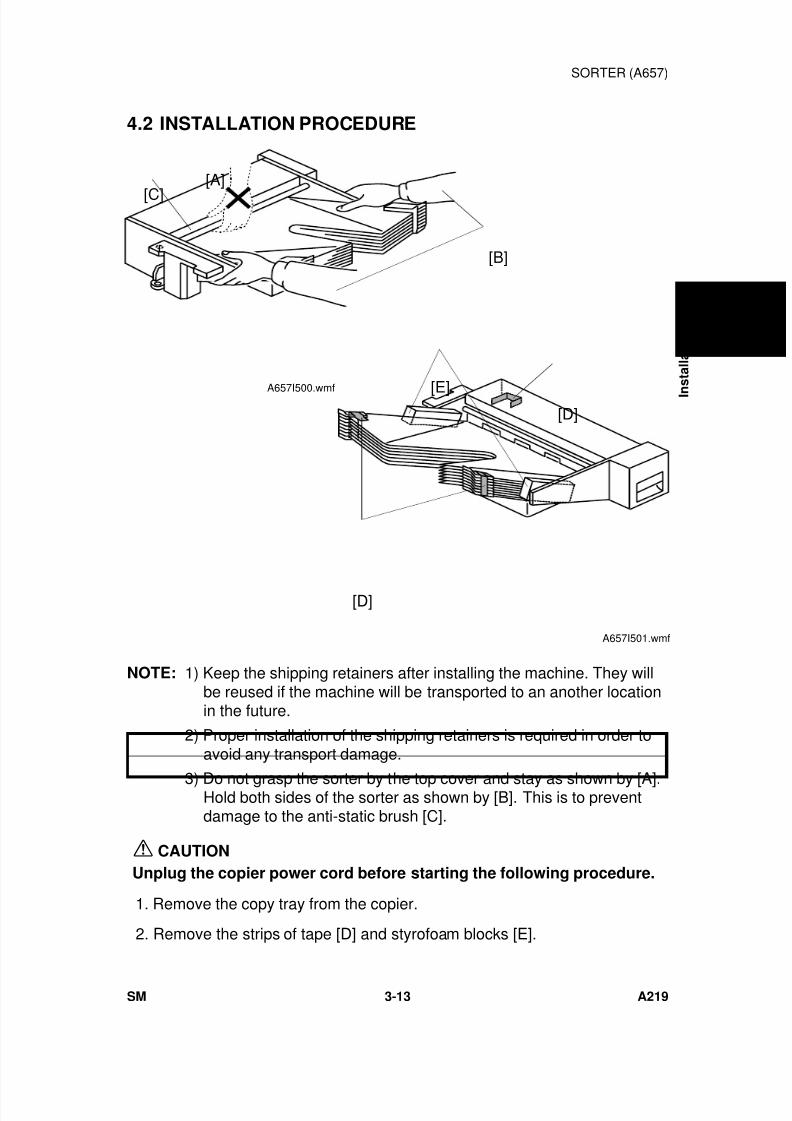
7/18/2019 A219 245 B019 4015 3813 Service
http://slidepdf.com/reader/full/a219-245-b019-4015-3813-service 114/372
4.2 INSTALLATION PROCEDURE
NOTE: 1) Keep the shipping retainers after installing the machine. They willbe reused if the machine will be transported to an another locationin the future.
2) Proper installation of the shipping retainers is required in order toavoid any transport damage.
3) Do not grasp the sorter by the top cover and stay as shown by [A].Hold both sides of the sorter as shown by [B]. This is to preventdamage to the anti-static brush [C].
CAUTION
Unplug the copier power cord before starting the following procedure.
1. Remove the copy tray from the copier.
2. Remove the strips of tape [D] and styrofoam blocks [E].
[C]
[A]
[B]
A657I500.wmf
[D]
[D]
[E]
A657I501.wmf
I n
s t a l l a t i o n
SORTER (A657)
SM 3-13 A219
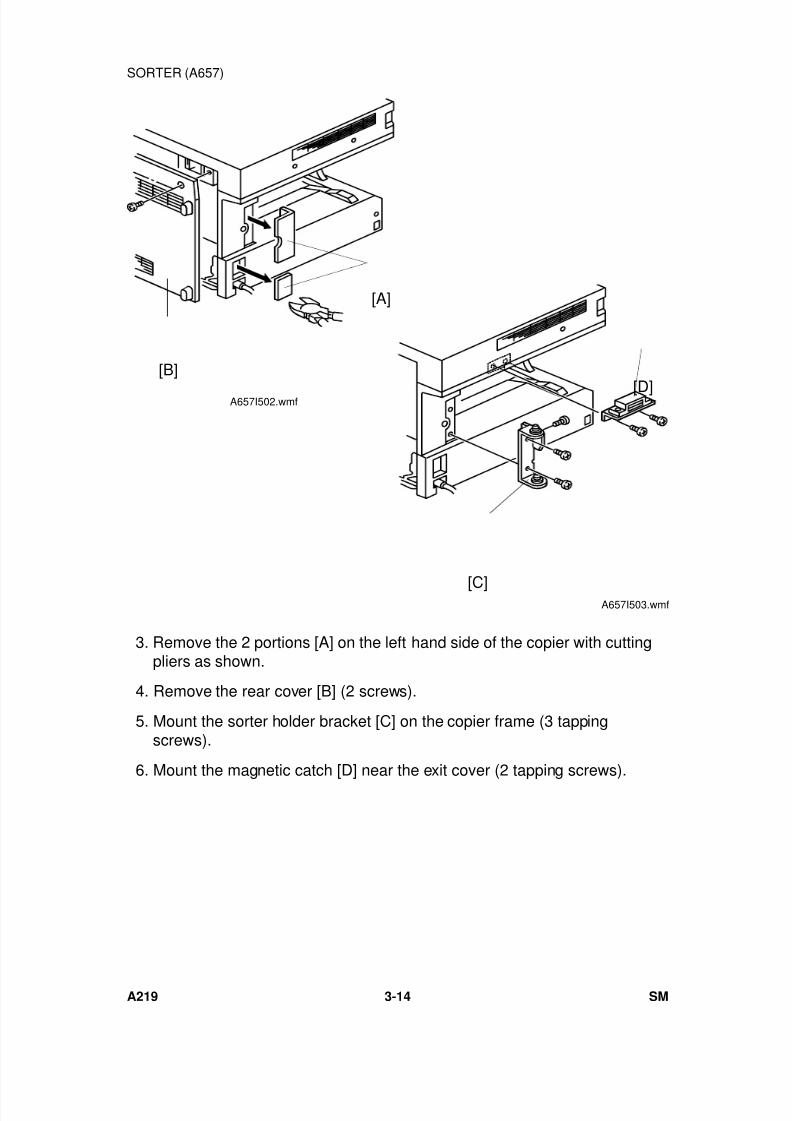
7/18/2019 A219 245 B019 4015 3813 Service
http://slidepdf.com/reader/full/a219-245-b019-4015-3813-service 115/372
3. Remove the 2 portions [A] on the left hand side of the copier with cuttingpliers as shown.
4. Remove the rear cover [B] (2 screws).
5. Mount the sorter holder bracket [C] on the copier frame (3 tappingscrews).
6. Mount the magnetic catch [D] near the exit cover (2 tapping screws).
[B]
[A]
A657I502.wmf [D]
[C]A657I503.wmf
SORTER (A657)
A219 3-14 SM
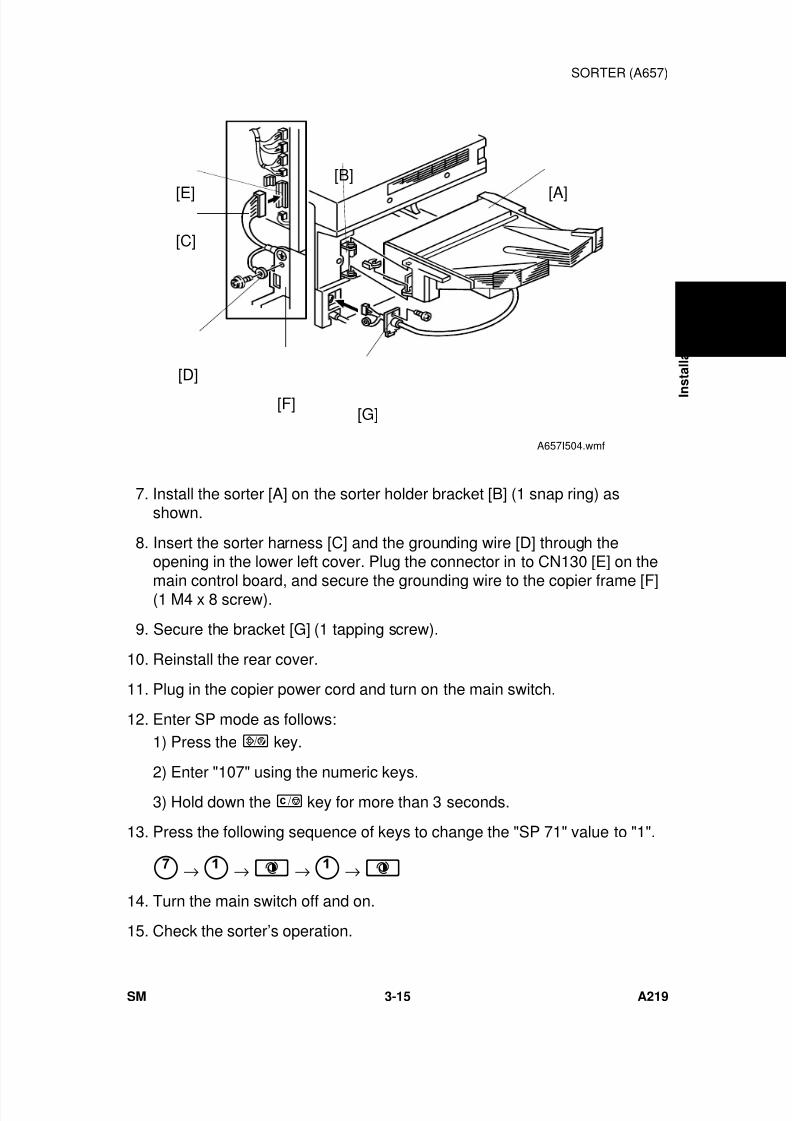
7/18/2019 A219 245 B019 4015 3813 Service
http://slidepdf.com/reader/full/a219-245-b019-4015-3813-service 116/372
7. Install the sorter [A] on the sorter holder bracket [B] (1 snap ring) asshown.
8. Insert the sorter harness [C] and the grounding wire [D] through theopening in the lower left cover. Plug the connector in to CN130 [E] on the
main control board, and secure the grounding wire to the copier frame [F](1 M4 x 8 screw).
9. Secure the bracket [G] (1 tapping screw).
10. Reinstall the rear cover.
11. Plug in the copier power cord and turn on the main switch.
12. Enter SP mode as follows:1) Press the key.
2) Enter "107" using the numeric keys.3) Hold down the key for more than 3 seconds.
13. Press the following sequence of keys to change the "SP 71" value to "1".
→ → → →
14. Turn the main switch off and on.
15. Check the sorter’s operation.
[E]
[C]
[D]
[F][G]
[A]
[B]
A657I504.wmf
I n
s t a l l a t i o n
SORTER (A657)
SM 3-15 A219
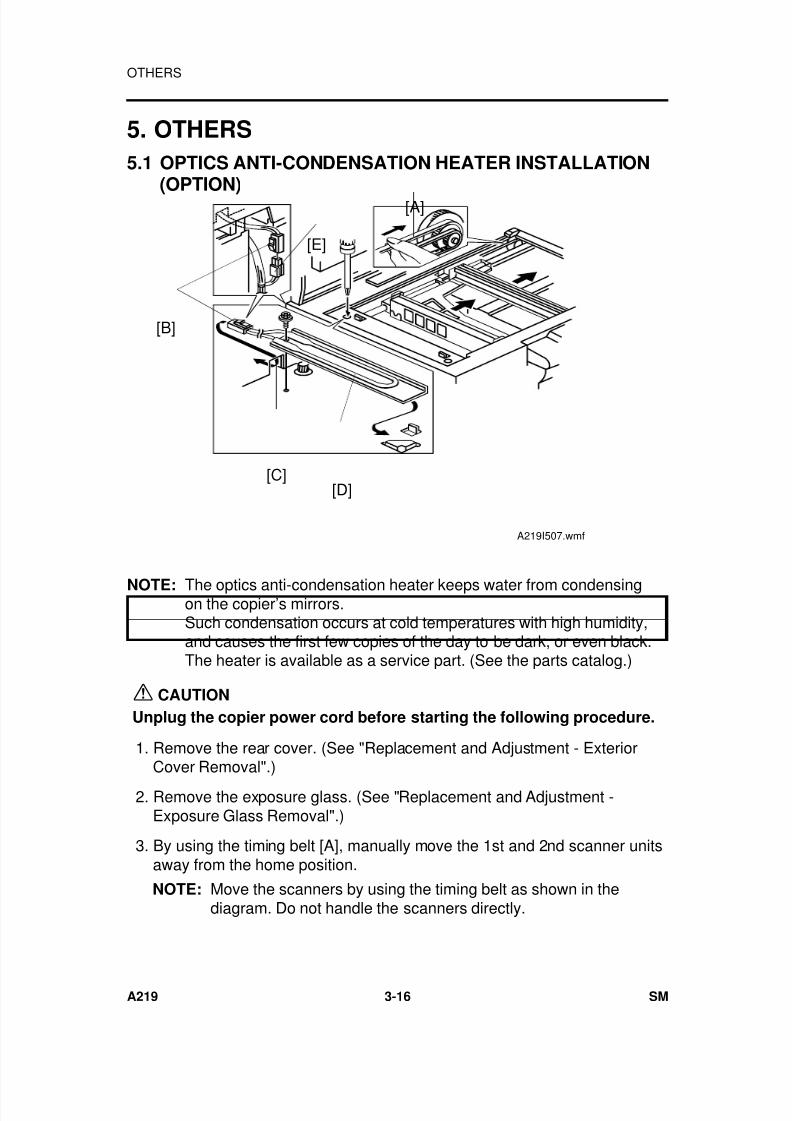
7/18/2019 A219 245 B019 4015 3813 Service
http://slidepdf.com/reader/full/a219-245-b019-4015-3813-service 117/372
5. OTHERS
5.1 OPTICS ANTI-CONDENSATION HEATER INSTALLATION
(OPTION)
NOTE: The optics anti-condensation heater keeps water from condensingon the copier’s mirrors.Such condensation occurs at cold temperatures with high humidity,and causes the first few copies of the day to be dark, or even black.The heater is available as a service part. (See the parts catalog.)
CAUTION
Unplug the copier power cord before starting the following procedure.
1. Remove the rear cover. (See "Replacement and Adjustment - ExteriorCover Removal".)
2. Remove the exposure glass. (See "Replacement and Adjustment -Exposure Glass Removal".)
3. By using the timing belt [A], manually move the 1st and 2nd scanner unitsaway from the home position.
NOTE: Move the scanners by using the timing belt as shown in thediagram. Do not handle the scanners directly.
[A]
[E]
[B]
[C][D]
A219I507.wmf
OTHERS
A219 3-16 SM

7/18/2019 A219 245 B019 4015 3813 Service
http://slidepdf.com/reader/full/a219-245-b019-4015-3813-service 118/372
4. Pass the connector [B] through the opening [C], and mount theanit-condensation heater [D] as shown (1 screw).
5. Connect the red two-pin connector [E] at the rear of the copier to the
heater’s connector [B] (red).
6. Make sure that scanner drive belt and mirrors do not touch the heaterharness while they are functioning.
NOTE: Tell the customer that even when the copier main switch is turnedoff, the copier power cord should be plugged in. Otherwise, theoptics anti-condensation heater will not function.
I n
s t a l l a t i o n
OTHERS
SM 3-17 A219
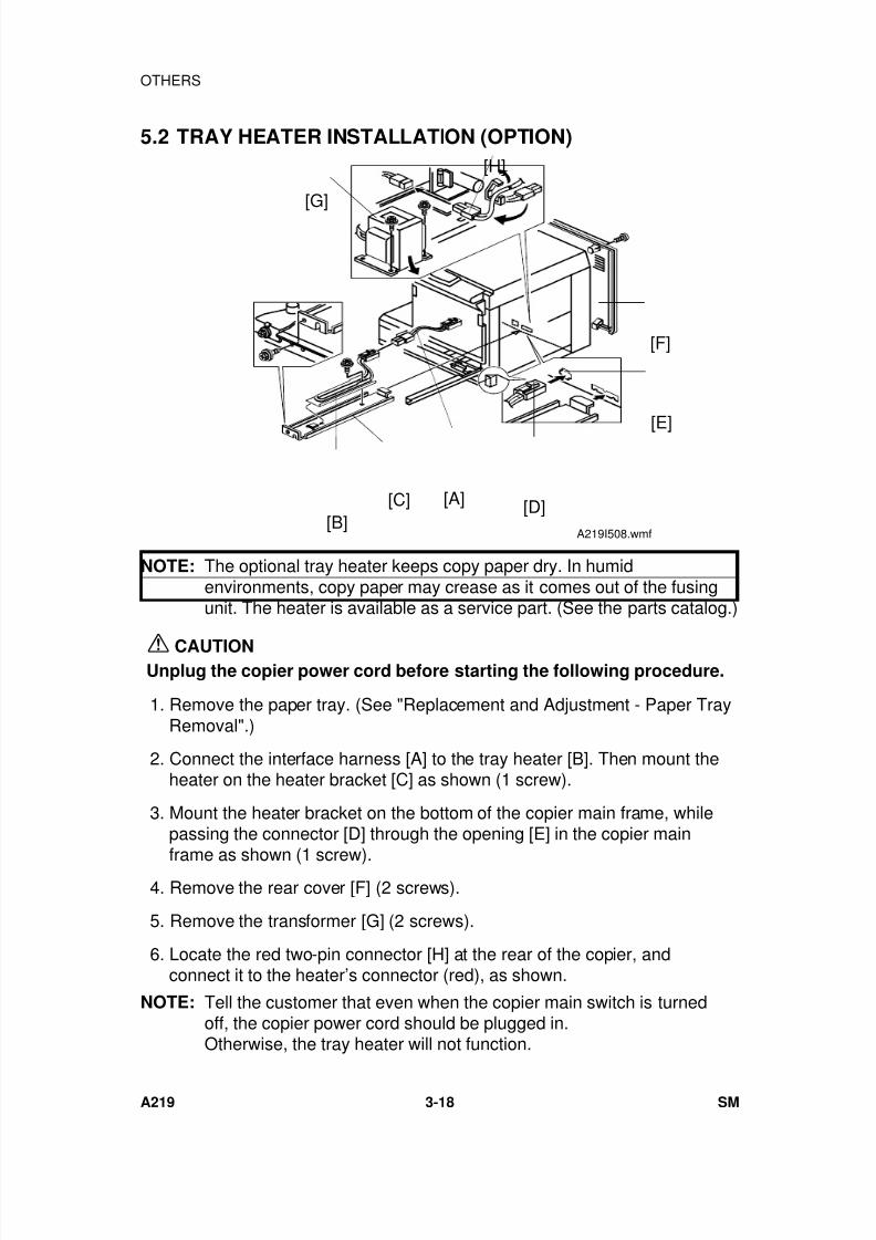
7/18/2019 A219 245 B019 4015 3813 Service
http://slidepdf.com/reader/full/a219-245-b019-4015-3813-service 119/372
5.2 TRAY HEATER INSTALLATION (OPTION)
NOTE: The optional tray heater keeps copy paper dry. In humidenvironments, copy paper may crease as it comes out of the fusingunit. The heater is available as a service part. (See the parts catalog.)
CAUTIONUnplug the copier power cord before starting the following procedure.
1. Remove the paper tray. (See "Replacement and Adjustment - Paper TrayRemoval".)
2. Connect the interface harness [A] to the tray heater [B]. Then mount theheater on the heater bracket [C] as shown (1 screw).
3. Mount the heater bracket on the bottom of the copier main frame, whilepassing the connector [D] through the opening [E] in the copier main
frame as shown (1 screw). 4. Remove the rear cover [F] (2 screws).
5. Remove the transformer [G] (2 screws).
6. Locate the red two-pin connector [H] at the rear of the copier, andconnect it to the heater’s connector (red), as shown.
NOTE: Tell the customer that even when the copier main switch is turnedoff, the copier power cord should be plugged in.Otherwise, the tray heater will not function.
[H]
[G]
[F]
[E]
[D][C][B]
[A]
A219I508.wmf
OTHERS
A219 3-18 SM

7/18/2019 A219 245 B019 4015 3813 Service
http://slidepdf.com/reader/full/a219-245-b019-4015-3813-service 120/372
SERVICE TABLES

7/18/2019 A219 245 B019 4015 3813 Service
http://slidepdf.com/reader/full/a219-245-b019-4015-3813-service 121/372
7/18/2019 A219 245 B019 4015 3813 Service
http://slidepdf.com/reader/full/a219-245-b019-4015-3813-service 122/372
1. SERVICE REMARKS
1.1 GENERAL CAUTIONS
1. To prevent physical injury, keep hands away from the mechanical drivecomponents when the main switch is on (especially during the warm-upcycle).If the key is pressed before the copier finishes the warm-up cycle,the Start indicator starts blinking and the copier starts making copies assoon as the warm-up cycle is completed.
2. Before disassembling or assembling any parts of the copier, make surethat the power cord is unplugged.
1.2 IMAGING UNIT
1. Always ensure the following when removing the imaging unit from thecopier.
• Do not touch the drum surface with bare hands. When the drumsurface is touched with fingers or becomes dirty, wipe it with a drycloth.
• Place the imaging unit on a clean and level place. Take care not toscratch the drum from under the unit as there is no cover to protect it.
•
Cover the imaging unit with sheets of paper to prevent the drum frombeing exposed to light.• Do not turn the imaging unit upside down. Toner and developer may
fall out from the unit.
2. Before pulling out the imaging unit, place a sheet of paper under the unitto catch any spilled toner.
3. Never use alcohol to clean the drum; alcohol dissolves the drum surface.
4. Take care not to scratch the drum as the photoconductive layer is thinand is easily damaged.
5. Never expose the drum to corrosive gases such as ammonia gas.
6. Store the imaging unit in a cool, dry place away from heat.
7. Do not touch the charge corona wire or the grid plate with bare hands. Oilstains may cause uneven image density on copies.
8. Clean the charge corona wire by pulling on the wire cleaning knob.
9. Clean the charge grid with a blower brush (not with a cloth).
S e r v i c e
T a b l e s
SERVICE REMARKS
SM 4-1 A219
7/18/2019 A219 245 B019 4015 3813 Service
http://slidepdf.com/reader/full/a219-245-b019-4015-3813-service 123/372
10. Be careful not to damage the edge of the cleaning blade.
11. After installing a new cleaning blade, be sure to apply setting powderevenly on the surface and edge of the blade.
12. When installing a NEW drum, do the following:1) Apply setting powder to the entire surface of the drum.
2) Reinstall the drum and all other parts. Perform SP93 (VR CorrectionReset).
3) Open SP33 (Image Bias Adjustment - Manual ID Mode) and return thesetting to the normal value if it has been changed.
4) SP48 (Light Intensity Adjustment) - see the SP mode table for details.
5) SP56 (ADS Reference Voltage Adjustment) - see the SP mode tablefor details.
13. When replacing developer, make sure that all toner and developer arecleaned from inside the imaging unit.
14. After installing NEW developer, reinstall the machine and perform SP66(TD Sensor Initial Setting).
1.3 OPTICS 1. Clean the exposure glass with glass cleaner and a dry cloth to reduce the
amount of static electricity on the glass surface.
2. Only use a clean soft cloth to clean the mirrors and reflectors.
3. Only use a blower brush to clean the 6th mirror and the lens.
4. Do not touch the following parts with bare hands:1) Reflectors
2) Exposure Lamp
3) Mirrors and Lens
5. Do not change the cutout position of the reflectors as they are adjusted atthe factory.
6. Always replace the 1st scanner unit as an assembly, as the matching ofeach set of exposure lamp and reflectors is performed at the factory.
7. Only use the scanner timing belts when manually moving the scannerunits.
SERVICE REMARKS
A219 4-2 SM
7/18/2019 A219 245 B019 4015 3813 Service
http://slidepdf.com/reader/full/a219-245-b019-4015-3813-service 124/372
8. Whenever cleaning or replacing the optics, all the following actions mustbe done in order.1) Optics cleaning
2) Open SP33 (Image Bias Adjustment - Manual ID Mode) and return thesetting to the normal value if it has been changed.
3) SP48 (Light Intensity Adjustment) - see the SP mode table for details
4) SP56 (ADS Reference Voltage Adjustment) - see the SP mode tablefor details
1.4 TRANSFER CORONA 1. Clean the corona wire and casing with a blower brush.
2. Never loosen the two screws securing the entrance guide plate. Theposition is set with a special instrument at the factory to ensure properimage transfer onto the copy paper.
1.5 FUSING UNIT
1. Be careful not to damage the edges of the hot roller strippers or theirtension springs.
2. Do not touch the fusing lamp with bare hands.
3. Make sure that both fusing lamp insulators are properly set in the holders.
4. When handling the fusing unit, hold the unit by the bottom frame. Do notgrasp it by the hot roller stripper bracket or by the fusing entrance guideas they are easily damaged. The upper frame tends to hold more heatthan the lower frame. Be careful.
5. Do not rotate the rollers while the pressure springs are not installed andthe hot roller strippers are in place. If done, the hot roller may bedamaged by the strippers.
S e r v i c e
T a b l e s
SERVICE REMARKS
SM 4-3 A219
7/18/2019 A219 245 B019 4015 3813 Service
http://slidepdf.com/reader/full/a219-245-b019-4015-3813-service 125/372
1.6 PAPER FEED
1. Do not touch the feed rollers with bare hands.
2. The side fences and the end fence of the paper tray should be positionedcorrectly so that they securely hold the paper. Make sure the stack ofpaper is aligned, and that there is no space between the side guides andthe paper stack.
3. Always push the paper tray in gently. The paper stack might go over theside fence or the corner separators, causing double feed or imageskewing problems.
4. Avoid storing paper for a long time.At high temperature and high humidity, or at low temperature and lowhumidity, store paper in a plastic bag. This is especially important to
decrease the amount of curls or waves that would lead to paper misfeeds.
5. Find out if the customer changes the paper size in the paper trayfrequently. If not, inform the customer that the side guides can be fixedwith a screw to achieve better paper feed quality (use tapping screw M3 x8).
1.7 OTHERS
1. When replacing the main board, remove the EEPROM (IC112) from theold main board and place it on the new main board. Then install the newmain board in the copier.
2. After installing a new main board with a new EEPROM (IC112), the ClearAll Memory (SP99) procedure must be performed. (Do not perform SP99if you have placed the old EEPROM on the new main board.)
3. Never perform SP99 (Clear All Memory) except for the following twocases:a) When the copier malfunctions due to a damaged EEPROM.
b) When replacing the EEPROM.
4. Whenever SP99 (Clear All Memory) is performed, the drum anddeveloper must be replaced with new ones. Otherwise, copy quality mightbe seriously affected.
SERVICE REMARKS
A219 4-4 SM

7/18/2019 A219 245 B019 4015 3813 Service
http://slidepdf.com/reader/full/a219-245-b019-4015-3813-service 126/372
5. Securely tighten the screws used for grounding the following PCBs whenreinstalling them.
• Main Control Board
• AC Drive/DC Power Supply Board• High Voltage Supply Board C/G/B/T/S
6. If the optional tray and anti-condensation heaters have been installed,keep the copier power cord plugged in, even when the copier main switchis turned off. This keeps the heaters energized.
S e r v i c e
T a b l e s
SERVICE REMARKS
SM 4-5 A219
7/18/2019 A219 245 B019 4015 3813 Service
http://slidepdf.com/reader/full/a219-245-b019-4015-3813-service 127/372
2. PROGRAM MODES
2.1 BASIC OPERATION
1. ComponentThis copier is equipped with two program modes. One is the Service Program(SP) Mode for factory and field technician usage, and the other is the UserProgram (UP) mode for the user. Both program modes have a differentaccess procedure, but all the UP mode functions can be accessed from theSP mode.
To be able to reset a service call (E5) condition using SP mode, the SP modecan be accessed while the error condition exists. The error code will not bedisplayed in the copy counter during these conditions.
2. Operation
To access these program modes, certain keys must be pressed after turningon the main switch. After accessing, select the required mode number andperform the procedure needed for that function. It is possible to move on tothe next required mode without exiting each time.
To exit these modes, turn the main switch off/on.
3. Display
The Copy Counter is used to display the program mode number. TheMagnification Ratio display is used to display the current value.
When the Copy Counter is blinking, and the dot is lit, the machine is readyto accept a program mode number. (The program mode number isdisplayed when you input it.) The Magnification Ratio display is blinking atthis time.
When the Copy Counter stops blinking, and the dot starts blinking, themachine is ready to accept an adjustment value, and it may be displayingthe current adjustment value on the Magnification Ratio display.
4. Notes
1. With the exception of SP57, all copies made inside the programmodes are made with ID level 4 (center value).
PROGRAM MODES
A219 4-6 SM
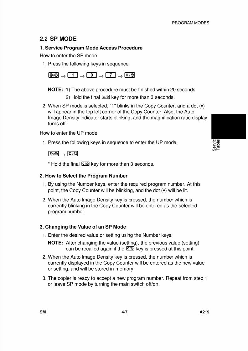
7/18/2019 A219 245 B019 4015 3813 Service
http://slidepdf.com/reader/full/a219-245-b019-4015-3813-service 128/372
2.2 SP MODE
1. Service Program Mode Access Procedure
How to enter the SP mode
1. Press the following keys in sequence.
→ → → →
NOTE: 1) The above procedure must be finished within 20 seconds.
2) Hold the final key for more than 3 seconds.
2. When SP mode is selected, "1" blinks in the Copy Counter, and a dot (•)will appear in the top left corner of the Copy Counter. Also, the AutoImage Density indicator starts blinking, and the magnification ratio display
turns off.
How to enter the UP mode
1. Press the following keys in sequence to enter the UP mode.
→
* Hold the final key for more than 3 seconds.
2. How to Select the Program Number
1. By using the Number keys, enter the required program number. At thispoint, the Copy Counter will be blinking, and the dot (•) will be lit.
2. When the Auto Image Density key is pressed, the number which iscurrently blinking in the Copy Counter will be entered as the selectedprogram number.
3. Changing the Value of an SP Mode
1. Enter the desired value or setting using the Number keys.
NOTE: After changing the value (setting), the previous value (setting)can be recalled again if the key is pressed at this point.
2. When the Auto Image Density key is pressed, the number which iscurrently displayed in the Copy Counter will be entered as the new valueor setting, and will be stored in memory.
3. The copier is ready to accept a new program number. Repeat from step 1or leave SP mode by turning the main switch off/on.
S e r v i c e
T a b l e s
PROGRAM MODES
SM 4-7 A219
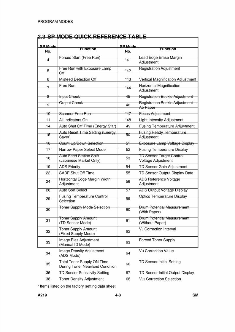
7/18/2019 A219 245 B019 4015 3813 Service
http://slidepdf.com/reader/full/a219-245-b019-4015-3813-service 129/372
2.3 SP MODE QUICK REFERENCE TABLE
SP ModeNo.
FunctionSP Mode
No.Function
4 Forced Start (Free Run) *41 Lead Edge Erase MarginAdjustment
5Free Run with Exposure LampOff
*42Registration Adjustment
6 Misfeed Detection Off *43 Vertical Magnification Adjustment
7 Free Run *44 Horizontal MagnificationAdjustment
8 Input Check 45 Registration Buckle Adjustment
9Output Check
46Registration Buckle Adjustment -A5 Paper
10 Scanner Free Run *47 Focus Adjustment11 All Indicators On *48 Light Intensity Adjustment
14 Auto Shut Off Time (Energy Star) 49 Fusing Temperature Adjustment
15Auto Reset Time Setting (EnergySaver)
50Fusing Ready TemperatureAdjustment
16 Count Up/Down Selection 51 Exposure Lamp Voltage Display
17 Narrow Paper Select Mode 52 Fusing Temperature Display
18 Auto Feed Station Shift(Japanese Market Only)
53 TD Sensor Target ControlVoltage Adjustment
19 ADS Priority 54 TD Sensor Gain Adjustment
22 SADF Shut Off Time 55 TD Sensor Output Display Data
24Horizontal Edge Margin WidthAdjustment
56ADS Reference VoltageAdjustment
28 Auto Sort Select 57 ADS Output Voltage Display
29Fusing Temperature ControlSelection
59Optics Temperature Display
30Toner Supply Mode Selection
60Drum Potential Measurement(With Paper)
31Toner Supply Amount(TD Sensor Mode)
61Drum Potential Measurement(Without Paper)
32 Toner Supply Amount(Fixed Supply Mode) 62 VL Correction Interval
33Image Bias Adjustment(Manual ID Mode)
63Forced Toner Supply
34Image Density Adjustment(ADS Mode)
64VR Correction Value
35Total Toner Supply ON TimeDuring Toner Near/End Condition
66TD Sensor Initial Setting
36 TD Sensor Sensitivity Setting 67 TD Sensor Initial Output Display
38 Toner Density Adjustment 68 VL2 Correction Selection
* Items listed on the factory setting data sheet
PROGRAM MODES
A219 4-8 SM
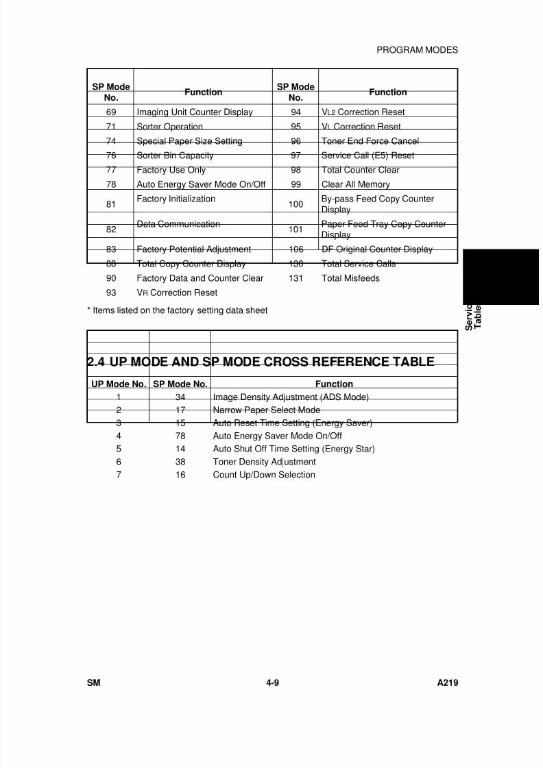
7/18/2019 A219 245 B019 4015 3813 Service
http://slidepdf.com/reader/full/a219-245-b019-4015-3813-service 130/372
SP ModeNo.
FunctionSP Mode
No.Function
69 Imaging Unit Counter Display 94 VL2 Correction Reset
71 Sorter Operation 95 VL Correction Reset
74 Special Paper Size Setting 96 Toner End Force Cancel
76 Sorter Bin Capacity 97 Service Call (E5) Reset
77 Factory Use Only 98 Total Counter Clear
78 Auto Energy Saver Mode On/Off 99 Clear All Memory
81Factory Initialization
100By-pass Feed Copy CounterDisplay
82Data Communication
101Paper Feed Tray Copy CounterDisplay
83 Factory Potential Adjustment 106 DF Original Counter Display
88 Total Copy Counter Display 130 Total Service Calls90 Factory Data and Counter Clear 131 Total Misfeeds
93 VR Correction Reset
* Items listed on the factory setting data sheet
2.4 UP MODE AND SP MODE CROSS REFERENCE TABLE
UP Mode No. SP Mode No. Function
1 34 Image Density Adjustment (ADS Mode)2 17 Narrow Paper Select Mode3 15 Auto Reset Time Setting (Energy Saver)4 78 Auto Energy Saver Mode On/Off5 14 Auto Shut Off Time Setting (Energy Star)6 38 Toner Density Adjustment7 16 Count Up/Down Selection
S e r v i c e
T a b l e s
PROGRAM MODES
SM 4-9 A219
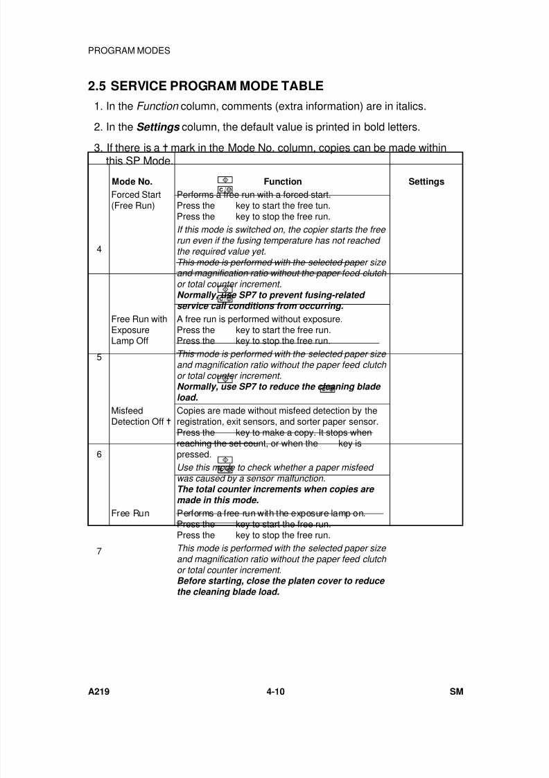
7/18/2019 A219 245 B019 4015 3813 Service
http://slidepdf.com/reader/full/a219-245-b019-4015-3813-service 131/372
2.5 SERVICE PROGRAM MODE TABLE
1. In the Function column, comments (extra information) are in italics.
2. In the Settings column, the default value is printed in bold letters.
3. If there is a mark in the Mode No. column, copies can be made withinthis SP Mode.
Mode No. Function Settings
4
Forced Start(Free Run)
Performs a free run with a forced start.Press the
key to start the free tun.Press the key to stop the free run.If this mode is switched on, the copier starts the free run even if the fusing temperature has not reached the required value yet.This mode is performed with the selected paper size
and magnification ratio without the paper feed clutch or total counter increment.Normally, use SP7 to prevent fusing-related service call conditions from occurring.
5
Free Run withExposureLamp Off
A free run is performed without exposure.Press the key to start the free run.Press the key to stop the free run.This mode is performed with the selected paper size and magnification ratio without the paper feed clutch or total counter increment.Normally, use SP7 to reduce the cleaning blade load.
6
MisfeedDetection Off
Copies are made without misfeed detection by theregistration, exit sensors, and sorter paper sensor.Press the
key to make a copy. It stops whenreaching the set count, or when the key ispressed.Use this mode to check whether a paper misfeed was caused by a sensor malfunction.The total counter increments when copies are made in this mode.
7
Free Run Performs a free run with the exposure lamp on.Press the
key to start the free run.Press the
key to stop the free run.This mode is performed with the selected paper size and magnification ratio without the paper feed clutch or total counter increment.Before starting, close the platen cover to reduce the cleaning blade load.
PROGRAM MODES
A219 4-10 SM
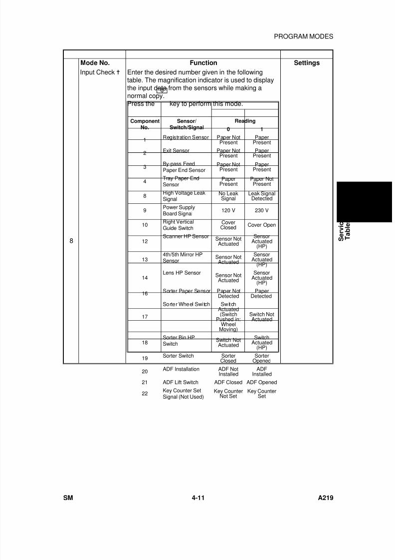
7/18/2019 A219 245 B019 4015 3813 Service
http://slidepdf.com/reader/full/a219-245-b019-4015-3813-service 132/372
Mode No. Function Settings
8
Input Check Enter the desired number given in the followingtable. The magnification indicator is used to displaythe input data from the sensors while making a
normal copy.Press the
key to perform this mode.
ComponentNo.
Sensor/Switch/Signal
Reading
0 1
1 Registration Sensor Paper NotPresent
PaperPresent
2 Exit Sensor Paper NotPresent
PaperPresent
3By-pass FeedPaper End Sensor
Paper NotPresent
PaperPresent
4Tray Paper EndSensor
PaperPresent
Paper NotPresent
8 High Voltage LeakSignal No LeakSignal Leak SignalDetected
9Power SupplyBoard Signal
120 V 230 V
10Right VerticalGuide Switch
CoverClosed Cover Open
12Scanner HP Sensor Sensor Not
ActuatedSensor
Actuated(HP)
134th/5th Mirror HPSensor
Sensor NotActuated
SensorActuated
(HP)
14Lens HP Sensor Sensor Not
ActuatedSensor
Actuated(HP)
16 Sorter Paper Sensor Paper NotDetected PaperDetected
17
Sorter Wheel Switch SwitchActuated(Switch
Pushed in:Wheel
Moving)
Switch NotActuated
18Sorter Bin HPSwitch
Switch NotActuated
SwitchActuated
(HP)
19 Sorter Switch SorterClosed
SorterOpened
20 ADF Installation ADF NotInstalled
ADFInstalled
21 ADF Lift Switch ADF Closed ADF Opened
22 Key Counter SetSignal (Not Used)
Key CounterNot Set
Key CounterSet
S e r v i c e
T a b l e s
PROGRAM MODES
SM 4-11 A219
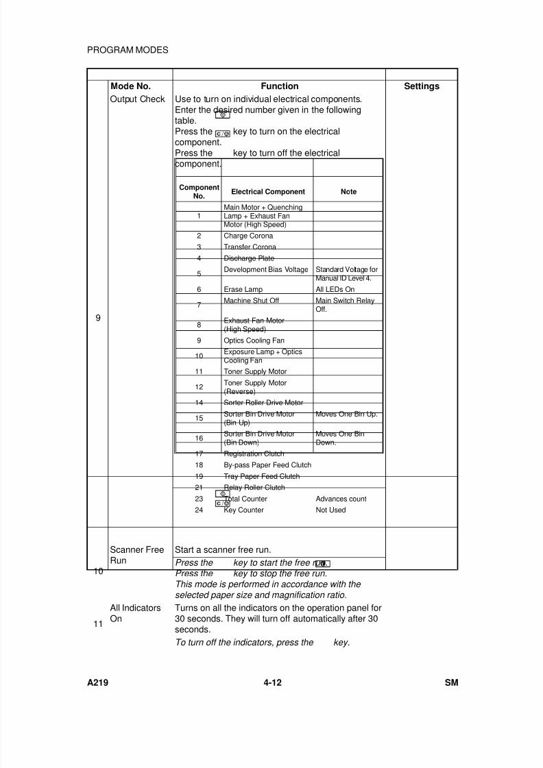
7/18/2019 A219 245 B019 4015 3813 Service
http://slidepdf.com/reader/full/a219-245-b019-4015-3813-service 133/372
Mode No. Function Settings
9
Output Check Use to turn on individual electrical components.Enter the desired number given in the followingtable.
Press the
key to turn on the electricalcomponent.Press the key to turn off the electricalcomponent.
10
Scanner FreeRun
Start a scanner free run.Press the
key to start the free run.Press the
key to stop the free run.This mode is performed in accordance with the selected paper size and magnification ratio.
11
All IndicatorsOn
Turns on all the indicators on the operation panel for30 seconds. They will turn off automatically after 30seconds.To turn off the indicators, press the
key.
ComponentNo.
Electrical Component Note
1Main Motor + QuenchingLamp + Exhaust FanMotor (High Speed)
2 Charge Corona
3 Transfer Corona
4 Discharge Plate
5 Development Bias Voltage Standard Voltage forManual ID Level 4.
6 Erase Lamp All LEDs On
7Machine Shut Off Main Switch Relay
Off.
8Exhaust Fan Motor(High Speed)
9 Optics Cooling Fan
10Exposure Lamp + OpticsCooling Fan
11 Toner Supply Motor
12 Toner Supply Motor(Reverse)
14 Sorter Roller Drive Motor
15 Sorter Bin Drive Motor(Bin Up)
Moves One Bin Up.
16Sorter Bin Drive Motor(Bin Down)
Moves One BinDown.
17 Registration Clutch
18 By-pass Paper Feed Clutch
19 Tray Paper Feed Clutch
21 Relay Roller Clutch
23 Total Counter Advances count
24 Key Counter Not Used
PROGRAM MODES
A219 4-12 SM
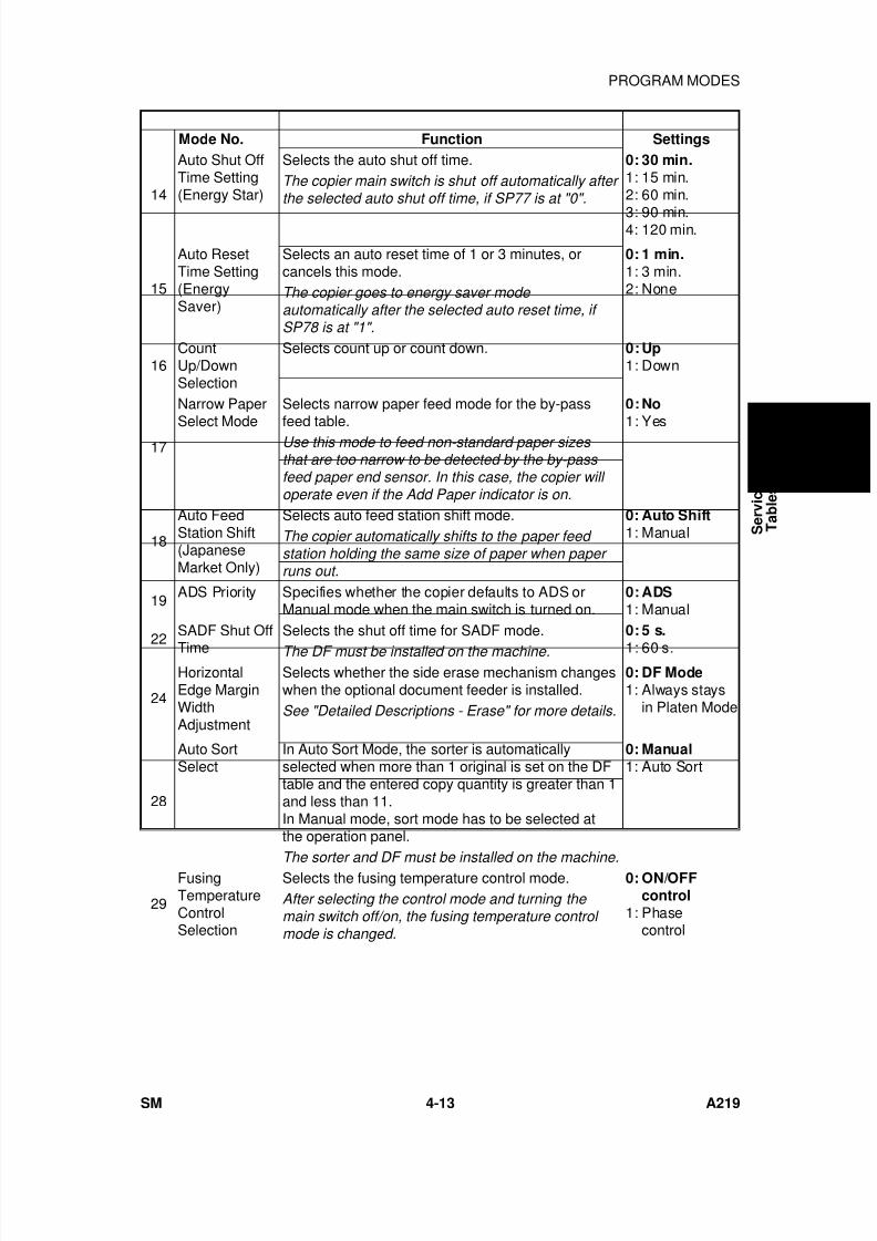
7/18/2019 A219 245 B019 4015 3813 Service
http://slidepdf.com/reader/full/a219-245-b019-4015-3813-service 134/372
Mode No. Function Settings
14
Auto Shut OffTime Setting(Energy Star)
Selects the auto shut off time. 0: 30 min.1: 15 min.2: 60 min.
3: 90 min.4: 120 min.
The copier main switch is shut off automatically after the selected auto shut off time, if SP77 is at "0".
15
Auto ResetTime Setting(EnergySaver)
Selects an auto reset time of 1 or 3 minutes, orcancels this mode.
0: 1 min.1: 3 min.2: NoneThe copier goes to energy saver mode
automatically after the selected auto reset time, if SP78 is at "1".
16CountUp/DownSelection
Selects count up or count down. 0: Up1: Down
17
Narrow PaperSelect Mode
Selects narrow paper feed mode for the by-passfeed table.
0: No1: Yes
Use this mode to feed non-standard paper sizes that are too narrow to be detected by the by-pass feed paper end sensor. In this case, the copier will operate even if the Add Paper indicator is on.
18
Auto FeedStation Shift(JapaneseMarket Only)
Selects auto feed station shift mode. 0: Auto Shift1: ManualThe copier automatically shifts to the paper feed
station holding the same size of paper when paper runs out.
19ADS Priority Specifies whether the copier defaults to ADS or
Manual mode when the main switch is turned on.0: ADS1: Manual
22
SADF Shut Off
Time
Selects the shut off time for SADF mode. 0: 5 s.
1: 60 s.The DF must be installed on the machine.
24
HorizontalEdge MarginWidthAdjustment
Selects whether the side erase mechanism changeswhen the optional document feeder is installed.
0: DF Mode1: Always stays
in Platen ModeSee "Detailed Descriptions - Erase" for more details.
28
Auto SortSelect
In Auto Sort Mode, the sorter is automaticallyselected when more than 1 original is set on the DFtable and the entered copy quantity is greater than 1and less than 11.In Manual mode, sort mode has to be selected atthe operation panel.
0: Manual1: Auto Sort
The sorter and DF must be installed on the machine.
29
FusingTemperatureControlSelection
Selects the fusing temperature control mode. 0: ON/OFFcontrol
1: Phasecontrol
After selecting the control mode and turning the main switch off/on, the fusing temperature control mode is changed.
S e r v i c e
T a b l e s
PROGRAM MODES
SM 4-13 A219
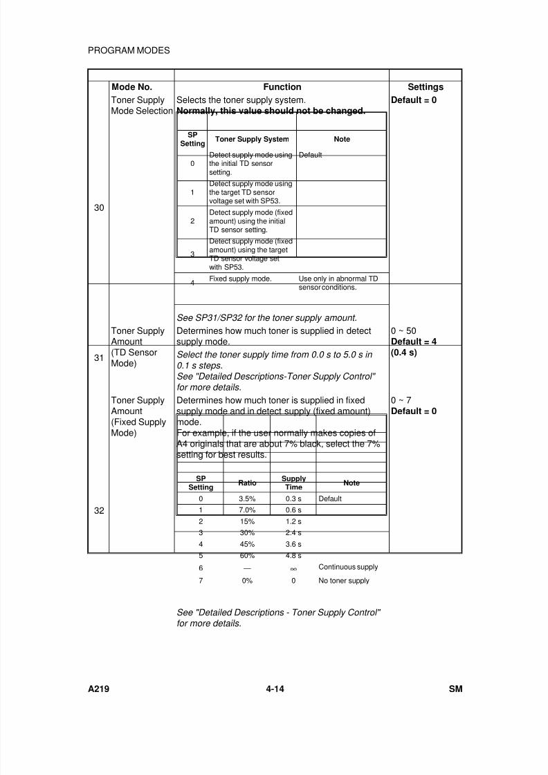
7/18/2019 A219 245 B019 4015 3813 Service
http://slidepdf.com/reader/full/a219-245-b019-4015-3813-service 135/372
Mode No. Function Settings
30
Toner SupplyMode Selection
Selects the toner supply system.Normally, this value should not be changed.
Default = 0
See SP31/SP32 for the toner supply amount.
31
Toner SupplyAmount(TD SensorMode)
Determines how much toner is supplied in detectsupply mode.
0 ~ 50Default = 4(0.4 s)Select the toner supply time from 0.0 s to 5.0 s in
0.1 s steps.See "Detailed Descriptions-Toner Supply Control" for more details.
32
Toner SupplyAmount(Fixed SupplyMode)
Determines how much toner is supplied in fixedsupply mode and in detect supply (fixed amount)mode.For example, if the user normally makes copies ofA4 originals that are about 7% black, select the 7%setting for best results.
0 ~ 7Default = 0
See "Detailed Descriptions - Toner Supply Control" for more details.
SPSetting
Toner Supply System Note
0Detect supply mode usingthe initial TD sensorsetting.
Default
1Detect supply mode usingthe target TD sensorvoltage set with SP53.
2Detect supply mode (fixedamount) using the initialTD sensor setting.
3
Detect supply mode (fixedamount) using the targetTD sensor voltage set
with SP53.4 Fixed supply mode. Use only in abnormal TD
sensor conditions.
SPSetting
RatioSupplyTime
Note
0 3.5% 0.3 s Default
1 7.0% 0.6 s
2 15% 1.2 s
3 30% 2.4 s
4 45% 3.6 s
5 60% 4.8 s
6 — ∞ Continuous supply
7 0% 0 No toner supply
PROGRAM MODES
A219 4-14 SM
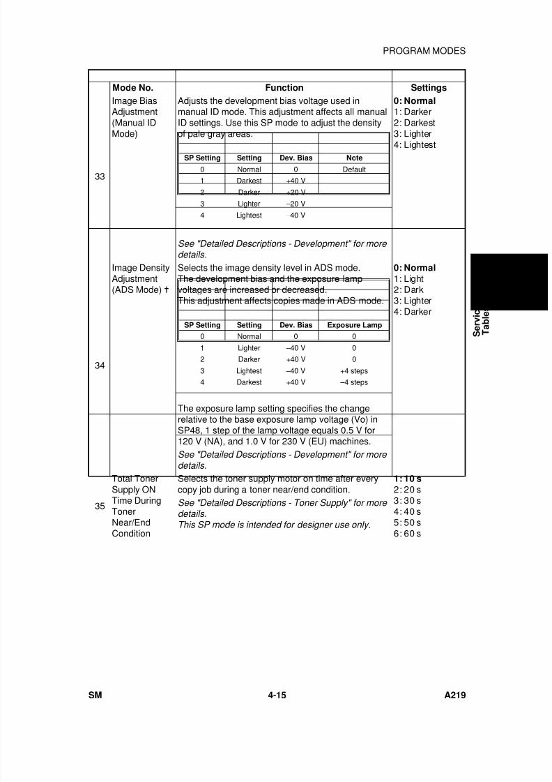
7/18/2019 A219 245 B019 4015 3813 Service
http://slidepdf.com/reader/full/a219-245-b019-4015-3813-service 136/372
Mode No. Function Settings
33
Image BiasAdjustment(Manual ID
Mode)
Adjusts the development bias voltage used inmanual ID mode. This adjustment affects all manualID settings. Use this SP mode to adjust the density
of pale gray areas.
0: Normal1: Darker2: Darkest
3: Lighter4: Lightest
See "Detailed Descriptions - Development" for more details.
34
Image DensityAdjustment(ADS Mode)
Selects the image density level in ADS mode.The development bias and the exposure lampvoltages are increased or decreased.This adjustment affects copies made in ADS mode.
The exposure lamp setting specifies the changerelative to the base exposure lamp voltage (Vo) inSP48, 1 step of the lamp voltage equals 0.5 V for120 V (NA), and 1.0 V for 230 V (EU) machines.
0: Normal1: Light2: Dark3: Lighter4: Darker
See "Detailed Descriptions - Development" for more details.
35
Total TonerSupply ONTime DuringTonerNear/EndCondition
Selects the toner supply motor on time after everycopy job during a toner near/end condition.
1: 10 s2: 20 s3: 30 s4: 40 s5: 50 s6: 60 s
See "Detailed Descriptions - Toner Supply" for more details.This SP mode is intended for designer use only.
SP Setting Setting Dev. Bias Note
0 Normal 0 Default
1 Darkest +40 V
2 Darker +20 V
3 Lighter –20 V
4 Lightest –40 V
SP Setting Setting Dev. Bias Exposure Lamp
0 Normal 0 0
1 Lighter –40 V 0
2 Darker +40 V 0
3 Lightest –40 V +4 steps
4 Darkest +40 V –4 steps
S e r v i c e
T a b l e s
PROGRAM MODES
SM 4-15 A219
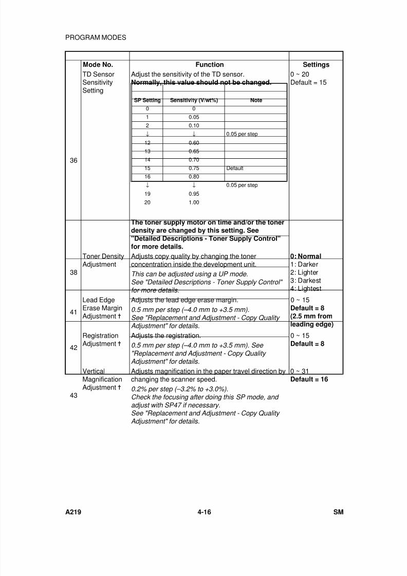
7/18/2019 A219 245 B019 4015 3813 Service
http://slidepdf.com/reader/full/a219-245-b019-4015-3813-service 137/372
Mode No. Function Settings
36
TD SensorSensitivitySetting
Adjust the sensitivity of the TD sensor.Normally, this value should not be changed.
The toner supply motor on time and/or the tonerdensity are changed by this setting. See"Detailed Descriptions - Toner Supply Control"for more details.
0 ~ 20Default = 15
38
Toner DensityAdjustment
Adjusts copy quality by changing the tonerconcentration inside the development unit.
0: Normal1: Darker2: Lighter3: Darkest4: Lightest
This can be adjusted using a UP mode.See "Detailed Descriptions - Toner Supply Control" for more details.
41Lead EdgeErase MarginAdjustment
Adjusts the lead edge erase margin. 0 ~ 15Default = 8(2.5 mm fromleading edge)
0.5 mm per step (–4.0 mm to +3.5 mm).See "Replacement and Adjustment - Copy Quality Adjustment" for details.
42
RegistrationAdjustment
Adjusts the registration. 0 ~ 15Default = 80.5 mm per step (–4.0 mm to +3.5 mm). See
"Replacement and Adjustment - Copy Quality Adjustment" for details.
43
VerticalMagnificationAdjustment
Adjusts magnification in the paper travel direction bychanging the scanner speed.
0 ~ 31Default = 16
0.2% per step (–3.2% to +3.0%).
Check the focusing after doing this SP mode, and adjust with SP47 if necessary.See "Replacement and Adjustment - Copy Quality Adjustment" for details.
SP Setting Sensitivity (V/wt%) Note0 0
1 0.05
2 0.10
↓ ↓ 0.05 per step
12 0.60
13 0.65
14 0.70
15 0.75 Default
16 0.80
↓ ↓ 0.05 per step
19 0.95
20 1.00
PROGRAM MODES
A219 4-16 SM
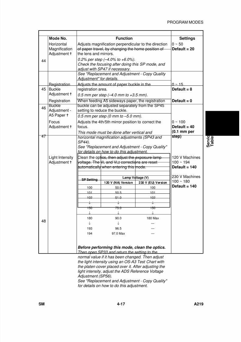
7/18/2019 A219 245 B019 4015 3813 Service
http://slidepdf.com/reader/full/a219-245-b019-4015-3813-service 138/372
Mode No. Function Settings
44
HorizontalMagnificationAdjustment
Adjusts magnification perpendicular to the directionof paper travel, by changing the home position ofthe lens and mirrors.
0 ~ 50Default = 20
0.2% per step (–4.0% to +6.0%).Check the focusing after doing this SP mode, and adjust with SP47 if necessary.See "Replacement and Adjustment - Copy Quality Adjustment" for details.
45RegistrationBuckleAdjustment
Adjusts the amount of paper buckle in theregistration area.
0 ~ 15Default = 8
0.5 mm per step (–4.0 mm to +3.5 mm).
46
RegistrationBuckleAdjustment -A5 Paper
When feeding A5 sideways paper, the registrationbuckle can be adjusted separately from the SP45setting to reduce the buckle.
Default = 0
0.5 mm per step (0 mm to –5.0 mm).
47
FocusAdjustment
Adjusts the 4th/5th mirror position to correct thefocus.
0 ~ 100Default = 40(0.1 mm perstep)
This mode must be done after vertical and horizontal magnification adjustments (SP43 and SP44).See "Replacement and Adjustment - Copy Quality" for details on how to do this adjustment.
48
Light IntensityAdjustment
Clean the optics, then adjust the exposure lampvoltage. The VL and VL2 corrections are resetautomatically when entering this mode.
120 V Machines100 ~ 194Default = 140
230 V Machines100 ~ 180Default = 140
Before performing this mode, clean the optics.Then open SP33 and return the setting to the normal value if it has been changed. Then adjust the light intensity using an OS-A3 Test Chart with the platen cover placed over it. After adjusting the light intensity, adjust the ADS Reference Voltage Adjustment (SP56).See "Replacement and Adjustment - Copy Quality" for details on how to do this adjustment.
SP Setting Lamp Voltage (V)120 V (NA) Version 230 V (EU) Version
100 50.0 100
101 50.5 101
102 51.0 102
↓ ↓ ↓
150 75.0 150
↓ ↓ ↓
180 90.0 180 Max
↓ ↓ —
193 96.5 —
194 97.0 Max —
S e r v i c e
T a b l e s
PROGRAM MODES
SM 4-17 A219

7/18/2019 A219 245 B019 4015 3813 Service
http://slidepdf.com/reader/full/a219-245-b019-4015-3813-service 139/372
Mode No. Function Settings
49
Fusing
Temperature
Adjustment
Adjusts the control temperature of the hot roller
during copying in 1°C steps.
120 V Machines
180°C ~ 195°C
Default = 190°C
230 V Machines
180°C ~ 200°C
Default = 190°C
50
Fusing Ready
Temperature
Adjustment
Adjusts the ready temperature of the hot roller
during the warm-up period in 1°C steps.
120 V Machines
160°C ~ 170°C
Default = 165°C
230 V Machines
165°C ~ 175°C
Default = 172°C
Normally, this value should not be changed.
51
ExposureLamp Voltage
Display
Displays the current exposure lamp voltage.For 120 V machines, the actual applied
voltage = displayed value/2
0 ~ 247
The exposure lamp turns on for 10 seconds when
this mode is selected. Do not repeat more than 5
times, to avoid overheating the optics cavity.
52
Fusing
Temperature
Display =
Displays the fusing temperature detected by the
fusing thermistor.
Press the! key to monitor the temperature
during the normal copy cycle.
53
TD Sensor
Target Control
Voltage Adjustment
If the setting of SP30 (Toner Supply Mode
Selection) is 1 or 3, this value is used for the TD
sensor target voltage.
1 ~ 200
Default = 97
(0.02 V per step)Normally, this value should not be changed.
54
TD Sensor
Gain
Adjustment
When the TD Sensor initial setting is performed, this
mode is adjusted automatically.
0 ~ 255
Default = 102
(0.04 V per
step)Normally, this value should not be changed.
55
TD Sensor
Output Display
Data =
Displays the TD sensor output voltage.
Press the! key to monitor the output voltage
during the normal copy cycle.
The output voltage will display "0" when this mode is
accessed after turning on the main switch without
making any copies.
(0.02 V per
step) x Data
56
ADS
Reference
Voltage
Adjustment
Adjusts the ADS reference voltage.
After adjusting the light intensity (SP48), place 5
sheets of A4(LT) white paper on the exposure glass
and select this mode. Adjust the ADS voltage to 2.5
V ± 0.1 V using VR101 on the main control board.
57
ADS Output
Voltage
Display =
Displays the ADS output voltage.
Press the! key to monitor the output voltage
during the normal copy cycle.
For only this SP mode, the copies are made with the
ADS mode (other SP modes use manual ID level 4).
Rev. 09/99
⇒
PROGRAM MODES
A219 4-18 SM
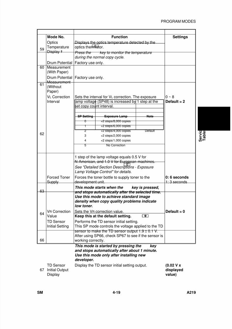
7/18/2019 A219 245 B019 4015 3813 Service
http://slidepdf.com/reader/full/a219-245-b019-4015-3813-service 140/372
Mode No. Function Settings
59
OpticsTemperatureDisplay
Displays the optics temperature detected by theoptics thermistor.Press the
key to monitor the temperature
during the normal copy cycle.
60Drum PotentialMeasurement(With Paper)
Factory use only.
61
Drum PotentialMeasurement(WithoutPaper)
Factory use only.
62
VL CorrectionInterval
Sets the interval for VL correction. The exposurelamp voltage (SP48) is increased by 1 step at theset copy count interval.
1 step of the lamp voltage equals 0.5 V forN-American, and 1.0 V for European machines.
0 ~ 8Default = 2
See "Detailed Section Descriptions - Exposure
Lamp Voltage Control" for details.
63
Forced TonerSupply
Forces the toner bottle to supply toner to thedevelopment unit.
0: 6 seconds
1: 3 secondsThis mode starts when the
key is pressed,and stops automatically after the selected time.Use this mode to achieve standard image density when copy quality problems indicate low toner.
64 VR CorrectionValue
Sets the VR correction value.Keep this at the default setting.
Default = 0
66
TD SensorInitial Setting
Performs the TD sensor initial setting.This SP mode controls the voltage applied to the TDsensor to make the TD sensor output 1.9 ± 0.1 V.After using SP66, check SP67 to see if the sensor isworking correctly.This mode is started by pressing the
key and stops automatically after about 1 minute.Use this mode only after installing new developer.
67TD SensorInitial OutputDisplay
Display the TD sensor initial setting output. (0.02 V xdisplayedvalue)
SP Setting Exposure Lamp Note
0 +2 steps/8,000 copies
1 +2 steps/6,000 copies
2 +2 steps/4,000 copies Default
3 +2 steps/2,000 copies
4 +2 steps/1,000 copies
5 No Correction
S e r v i c e
T a b l e s
PROGRAM MODES
SM 4-19 A219
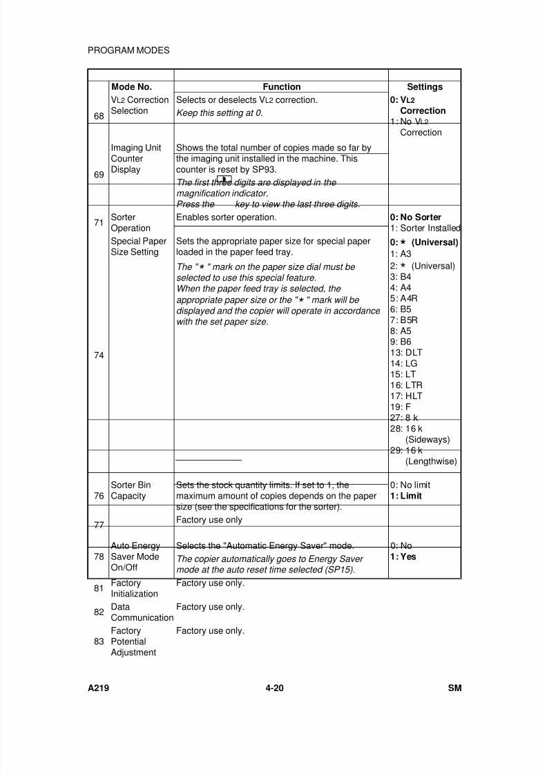
7/18/2019 A219 245 B019 4015 3813 Service
http://slidepdf.com/reader/full/a219-245-b019-4015-3813-service 141/372
Mode No. Function Settings
68
VL2 CorrectionSelection
Selects or deselects VL2 correction. 0: VL2
Correction1: No VL2
Correction
Keep this setting at 0.
69
Imaging UnitCounterDisplay
Shows the total number of copies made so far bythe imaging unit installed in the machine. Thiscounter is reset by SP93.The first three digits are displayed in the magnification indicator.Press the
key to view the last three digits.
71SorterOperation
Enables sorter operation. 0: No Sorter1: Sorter Installed
74
Special PaperSize Setting
Sets the appropriate paper size for special paperloaded in the paper feed tray.
0: * (Universal)
1: A3
2: * (Universal)3: B44: A45: A4R6: B57: B5R8: A59: B613: DLT14: LG15: LT16: LTR17: HLT19: F27: 8 k28: 16 k
(Sideways)29: 16 k
(Lengthwise)
The " * " mark on the paper size dial must be selected to use this special feature.When the paper feed tray is selected, the
appropriate paper size or the " * " mark will be displayed and the copier will operate in accordance with the set paper size.
76Sorter BinCapacity
Sets the stock quantity limits. If set to 1, themaximum amount of copies depends on the papersize (see the specifications for the sorter).
0: No limit1: Limit
77Factory use only
78Auto EnergySaver ModeOn/Off
Selects the "Automatic Energy Saver" mode. 0: No1: YesThe copier automatically goes to Energy Saver
mode at the auto reset time selected (SP15).
81FactoryInitialization
Factory use only.
82 DataCommunication
Factory use only.
83FactoryPotentialAdjustment
Factory use only.
PROGRAM MODES
A219 4-20 SM
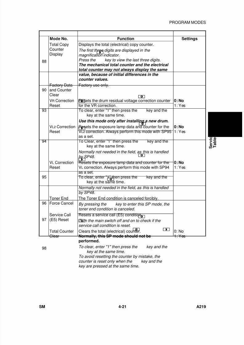
7/18/2019 A219 245 B019 4015 3813 Service
http://slidepdf.com/reader/full/a219-245-b019-4015-3813-service 142/372
Mode No. Function Settings
88
Total CopyCounterDisplay
Displays the total (electrical) copy counter.The first three digits are displayed in the magnification indicator.
Press the key to view the last three digits.The mechanical total counter and the electrical total counter may not always display the same value, because of initial differences in the counter values.
90Factory Dataand CounterClear
Factory use only.
93
VR CorrectionReset
Resets the drum residual voltage correction counterfor the VR correction.To clear, enter "1" then press the
key and the
key at the same time.
0: No1: Yes
Use this mode only after installing a new drum.
94
VL2 CorrectionReset
Resets the exposure lamp data and counter for theVL2 correction. Always perform this mode with SP95as a set.To Clear, enter "1" then press the
key and the
key at the same time.
0: No1: Yes
Normally not needed in the field, as this is handled by SP48.
95
VL CorrectionReset
Resets the exposure lamp data and counter for theVL correction. Always perform this mode with SP94as a set.To clear, enter "1" then press the
key and the key at the same time.
0: No1: Yes
Normally not needed in the field, as this is handled by SP48.
96Toner EndForce Cancel
The Toner End condition is canceled forcibly.By pressing the
key to enter this SP mode, the toner end condition is canceled.
97Service Call(E5) Reset
Resets a service call (E5) condition.Turn the main switch off and on to check if the service call condition is reset.
98
Total CounterClear
Clears the total (electrical) counter.Normally, this SP mode should not be
performed.
0: No1: Yes
To clear, enter "1" then press the
key and the
key at the same time.To avoid resetting the counter by mistake, the counter is reset only when the
key and the
key are pressed at the same time.
S e r v i c e
T a b l e s
PROGRAM MODES
SM 4-21 A219
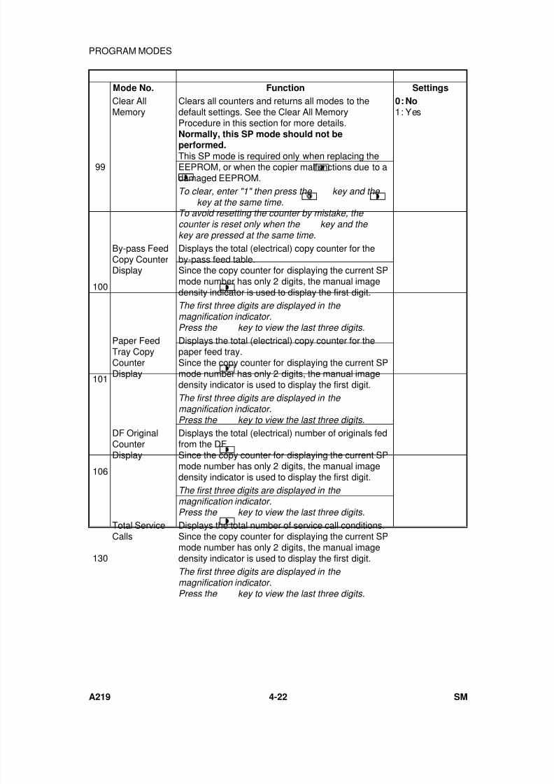
7/18/2019 A219 245 B019 4015 3813 Service
http://slidepdf.com/reader/full/a219-245-b019-4015-3813-service 143/372
Mode No. Function Settings
99
Clear AllMemory
Clears all counters and returns all modes to thedefault settings. See the Clear All MemoryProcedure in this section for more details.
Normally, this SP mode should not beperformed.
This SP mode is required only when replacing theEEPROM, or when the copier malfunctions due to adamaged EEPROM.
0: No1: Yes
To clear, enter "1" then press the
key and the
key at the same time.To avoid resetting the counter by mistake, the counter is reset only when the
key and the
key are pressed at the same time.
100
By-pass FeedCopy Counter
Display
Displays the total (electrical) copy counter for theby-pass feed table.
Since the copy counter for displaying the current SPmode number has only 2 digits, the manual imagedensity indicator is used to display the first digit.The first three digits are displayed in the magnification indicator.Press the
key to view the last three digits.
101
Paper FeedTray CopyCounterDisplay
Displays the total (electrical) copy counter for thepaper feed tray.Since the copy counter for displaying the current SPmode number has only 2 digits, the manual imagedensity indicator is used to display the first digit.The first three digits are displayed in the
magnification indicator.Press the
key to view the last three digits.
106
DF OriginalCounterDisplay
Displays the total (electrical) number of originals fedfrom the DF.Since the copy counter for displaying the current SPmode number has only 2 digits, the manual imagedensity indicator is used to display the first digit.The first three digits are displayed in the magnification indicator.Press the
key to view the last three digits.
130
Total ServiceCalls
Displays the total number of service call conditions.Since the copy counter for displaying the current SP
mode number has only 2 digits, the manual imagedensity indicator is used to display the first digit.The first three digits are displayed in the magnification indicator.Press the
key to view the last three digits.
PROGRAM MODES
A219 4-22 SM
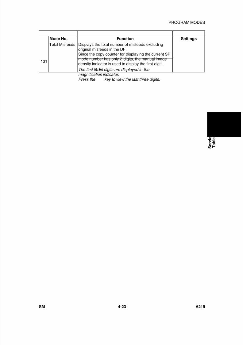
7/18/2019 A219 245 B019 4015 3813 Service
http://slidepdf.com/reader/full/a219-245-b019-4015-3813-service 144/372
Mode No. Function Settings
131
Total Misfeeds Displays the total number of misfeeds excludingoriginal misfeeds in the DF.Since the copy counter for displaying the current SP
mode number has only 2 digits, the manual imagedensity indicator is used to display the first digit.The first three digits are displayed in the magnification indicator.Press the
key to view the last three digits.
S e r v i c e
T a b l e s
PROGRAM MODES
SM 4-23 A219
7/18/2019 A219 245 B019 4015 3813 Service
http://slidepdf.com/reader/full/a219-245-b019-4015-3813-service 145/372
2.6 CLEAR ALL MEMORY PROCEDURE
WARNING:The Clear All Memory procedure (SP99) resets all the correctiondata for copy process control and all the software counters, and
returns all modes and adjustments to the default settings.Normally, this SP mode should not be performed.This procedure is required only when replacing the EEPROM orwhen the copier malfunctions due to a damaged EEPROM.
1. Enter SP99.
2. Enter "1".
3. Press the key and the key at the same time.
NOTE: To avoid resetting the memory by mistake, the memory is resetonly when the key and the key are pressed at the sametime.
4. Turn the main switch off and on.
- Recovering the machine after a memory reset -
WARNING:If SP99 is performed, all the software counters for processcontrol and the TD sensor initial setting data are reset. As aresult, the old drum and the old developer cannot be used any
more. Otherwise, dirty background and/or toner scattering willappear on copies sooner or later because proper process controlwill not be applied to the drum.After doing SP99, execute the following procedure to return themachine to its normal operating condition.
1. Install a new drum.
2. Install new developer.
3. Clean the optics and inside the copier if necessary.
PROGRAM MODES
A219 4-24 SM
7/18/2019 A219 245 B019 4015 3813 Service
http://slidepdf.com/reader/full/a219-245-b019-4015-3813-service 146/372
4. Refer to the "SP MODE FACTORY SETTING DATA" sheet locatedbehind the operation guide sheet installed on the front cover, and enterthe data that were stored in the following SP modes at the factory.
• SP41: Lead Edge Erase Margin• SP42: Registration Adjustment• SP43: Vertical Magnification Adjustment• SP44: Horizontal Magnification Adjustment• SP47: Focus Adjustment• SP48: Light Intensity Adjustment
5. Perform SP66 (TD Sensor Initial Setting).
NOTE: The machine will automatically stop when completed. (It takesabout 1 minute.)
6. Check the copy quality and the paper path and do any necessaryadjustment (see Replacement and Adjustment - Copy QualityAdjustments).
S e r v i c e
T a b l e s
PROGRAM MODES
SM 4-25 A219
7/18/2019 A219 245 B019 4015 3813 Service
http://slidepdf.com/reader/full/a219-245-b019-4015-3813-service 147/372
3. PRACTICAL SP MODE USE TABLE
The following table shows the SP modes that must be done, and the order inwhich they must be done when the listed items are replaced or cleaned.
No.SP
ModeNo.
Description
Replaced or Cleaned Item
Developer TD Sensor OPC DrumADS
Sensor
Optics(Scanner
Unit)
1 SP66TD SensorInitialSetting
2 SP93VRCorrection
Reset
*3 SP48LightIntensityAdjustment
4 SP56
ADSReferenceVoltageAdjustment
*NOTE: 1) Before performing SP48 (Light Intensity Adjustment), alwayscheck to see if the setting of SP33 (Image Bias Adjustment -Manual ID Mode) is set to the default value so that it is possible toadjust the light intensity properly.
2) The VL and VL2 corrections are reset automatically when enteringthis mode.
(Priority Number)
PRACTICAL SP MODE USE TABLE
A219 4-26 SM
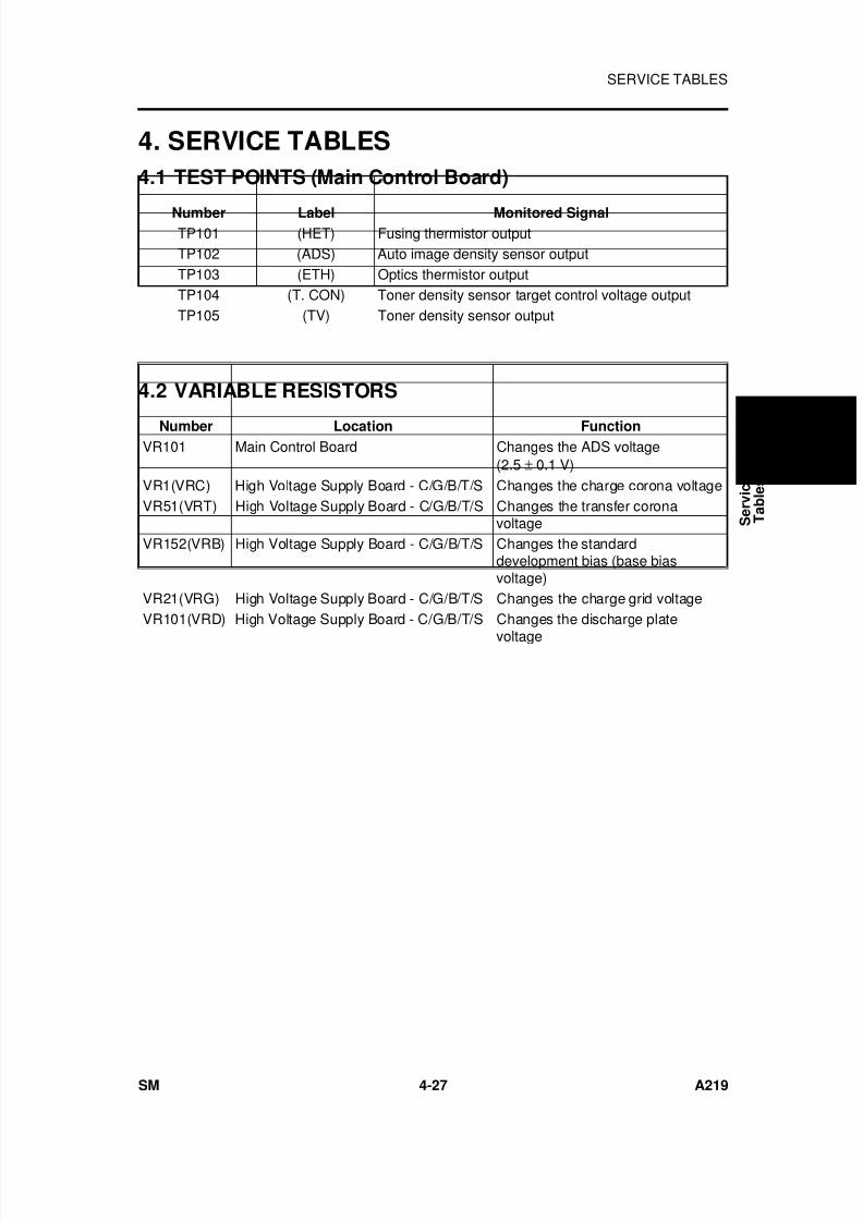
7/18/2019 A219 245 B019 4015 3813 Service
http://slidepdf.com/reader/full/a219-245-b019-4015-3813-service 148/372
4. SERVICE TABLES
4.1 TEST POINTS (Main Control Board)
Number Label Monitored SignalTP101 (HET) Fusing thermistor outputTP102 (ADS) Auto image density sensor outputTP103 (ETH) Optics thermistor outputTP104 (T. CON) Toner density sensor target control voltage outputTP105 (TV) Toner density sensor output
4.2 VARIABLE RESISTORS
Number Location FunctionVR101 Main Control Board Changes the ADS voltage
(2.5 ± 0.1 V)VR1(VRC) High Voltage Supply Board - C/G/B/T/S Changes the charge corona voltageVR51(VRT) High Voltage Supply Board - C/G/B/T/S Changes the transfer corona
voltageVR152(VRB) High Voltage Supply Board - C/G/B/T/S Changes the standard
development bias (base biasvoltage)
VR21(VRG) High Voltage Supply Board - C/G/B/T/S Changes the charge grid voltageVR101(VRD) High Voltage Supply Board - C/G/B/T/S Changes the discharge plate
voltage
S e r v i c e
T a b l e s
SERVICE TABLES
SM 4-27 A219

7/18/2019 A219 245 B019 4015 3813 Service
http://slidepdf.com/reader/full/a219-245-b019-4015-3813-service 149/372

7/18/2019 A219 245 B019 4015 3813 Service
http://slidepdf.com/reader/full/a219-245-b019-4015-3813-service 150/372
PREVENTIVE MAINTENANCE

7/18/2019 A219 245 B019 4015 3813 Service
http://slidepdf.com/reader/full/a219-245-b019-4015-3813-service 151/372
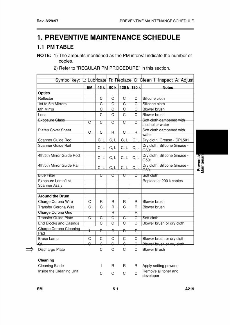
7/18/2019 A219 245 B019 4015 3813 Service
http://slidepdf.com/reader/full/a219-245-b019-4015-3813-service 152/372
1. PREVENTIVE MAINTENANCE SCHEDULE
1.1 PM TABLE
NOTE: 1) The amounts mentioned as the PM interval indicate the number ofcopies.
2) Refer to "REGULAR PM PROCEDURE" in this section.
Symbol key: L: Lubricate R: Replace C: Clean I: Inspect A: Adjust
EM 45 k 90 k 135 k 180 k Notes
Optics
Reflector C C C C Silicone cloth1st to 5th Mirrors C C C C Silicone cloth6th Mirror C C C C Blower brush
Lens C C C C Blower brushExposure Glass
C C C C CSoft cloth dampened withalcohol or water
Platen Cover SheetC C R C R
Soft cloth dampened withwater
Scanner Guide Rod C, L C, L C, L C, L Dry cloth, Grease - CPL501Scanner Guide Rail C, L C, L C, L C, L Dry cloth, Silicone Grease -
G5014th/5th Mirror Guide Rod C, L C, L C, L C, L Dry cloth, Silicone Grease -
G5014th/5th Mirror Guide Rail
C, L C, L C, L C, L
Dry cloth, Silicone Grease -
G501Blue Filter C C C C Soft clothExposure Lamp/1stScanner Ass’y
Replace at 200 k copies
Around the Drum
Charge Corona Wire C R R R R Blower brushTransfer Corona Wire C C R C R Blower brushCharge Corona Grid R RTransfer Guide Plate C C C C C Soft clothEnd Blocks and Casings C C C C Blower brush or dry clothCharge Corona CleaningPad
I R R R R
Erase Lamp C C C C C Blower brush or dry clothQL C C C C C Blower brush or dry clothDischarge Plate C C C C Blower Brush
Cleaning
Cleaning Blade I R R R Apply setting powderInside the Cleaning Unit
C C C CRemove all toner anddeveloper
Rev. 8/29/97
⇒
P r e v e n t i v e
M a
i n t e n a n c e
PREVENTIVE MAINTENANCE SCHEDULE
SM 5-1 A219
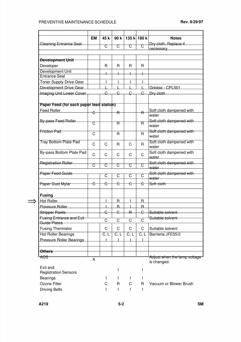
7/18/2019 A219 245 B019 4015 3813 Service
http://slidepdf.com/reader/full/a219-245-b019-4015-3813-service 153/372
EM 45 k 90 k 135 k 180 k Notes
Cleaning Entrance SealC C C C
Dry cloth. Replace ifnecessary
Development UnitDeveloper R R R RDevelopment UnitEntrance Seal
I I I I
Toner Supply Drive Gear I I I IDevelopment Drive Gear L L L L Grease - CPL501Imaging Unit Lower Cover C C C C Dry cloth
Paper Feed (for each paper feed station)
Feed Roller C R R Soft cloth dampened withwater
By-pass Feed Roller C R R Soft cloth dampened withwater
Friction PadC R R
Soft cloth dampened withwater
Tray Bottom Plate Pad C C R C R Soft cloth dampened withwater
By-pass Bottom Plate Pad C C C C C Soft cloth dampened withwater
Registration RollerC C C C C
Soft cloth dampened withwater
Paper Feed GuideC C C C
Soft cloth dampened with
waterPaper Dust Mylar C C C C C Soft cloth
Fusing
Hot Roller I R I RPressure Roller I R I RStripper Pawls C C R C Suitable solventFusing Entrance and ExitGuide Plates
C C C CSuitable solvent
Fusing Thermistor C C C C Suitable solventHot Roller Bearings C, L C, L C, L C, L Barrierta JFE55/2Pressure Roller Bearings I I I I
Others
ADS A Adjust when the lamp voltageis changed.
Exit andRegistration Sensors
I I
Bearings I I I IOzone Filter C R C R Vacuum or Blower BrushDriving Belts I I I I
⇒
Rev. 8/29/97PREVENTIVE MAINTENANCE SCHEDULE
A219 5-2 SM
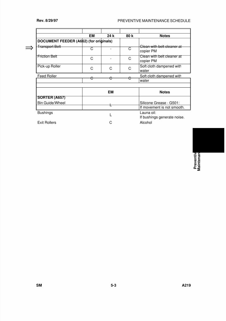
7/18/2019 A219 245 B019 4015 3813 Service
http://slidepdf.com/reader/full/a219-245-b019-4015-3813-service 154/372
EM 24 k 80 k Notes
DOCUMENT FEEDER (A662) (for originals)
Transport BeltC - C
Clean with belt cleaner atcopier PM
Friction Belt C - C Clean with belt cleaner atcopier PM
Pick-up RollerC C C
Soft cloth dampened withwater
Feed RollerC C C
Soft cloth dampened withwater
EM Notes
SORTER (A657)
Bin Guide/Wheel L Silicone Grease - G501:If movement is not smooth.
Bushings L Launa oil:If bushings generate noise.
Exit Rollers C Alcohol
Rev. 8/29/97
⇒
P r e v e n t i v e
M a
i n t e n a n c e
PREVENTIVE MAINTENANCE SCHEDULE
SM 5-3 A219
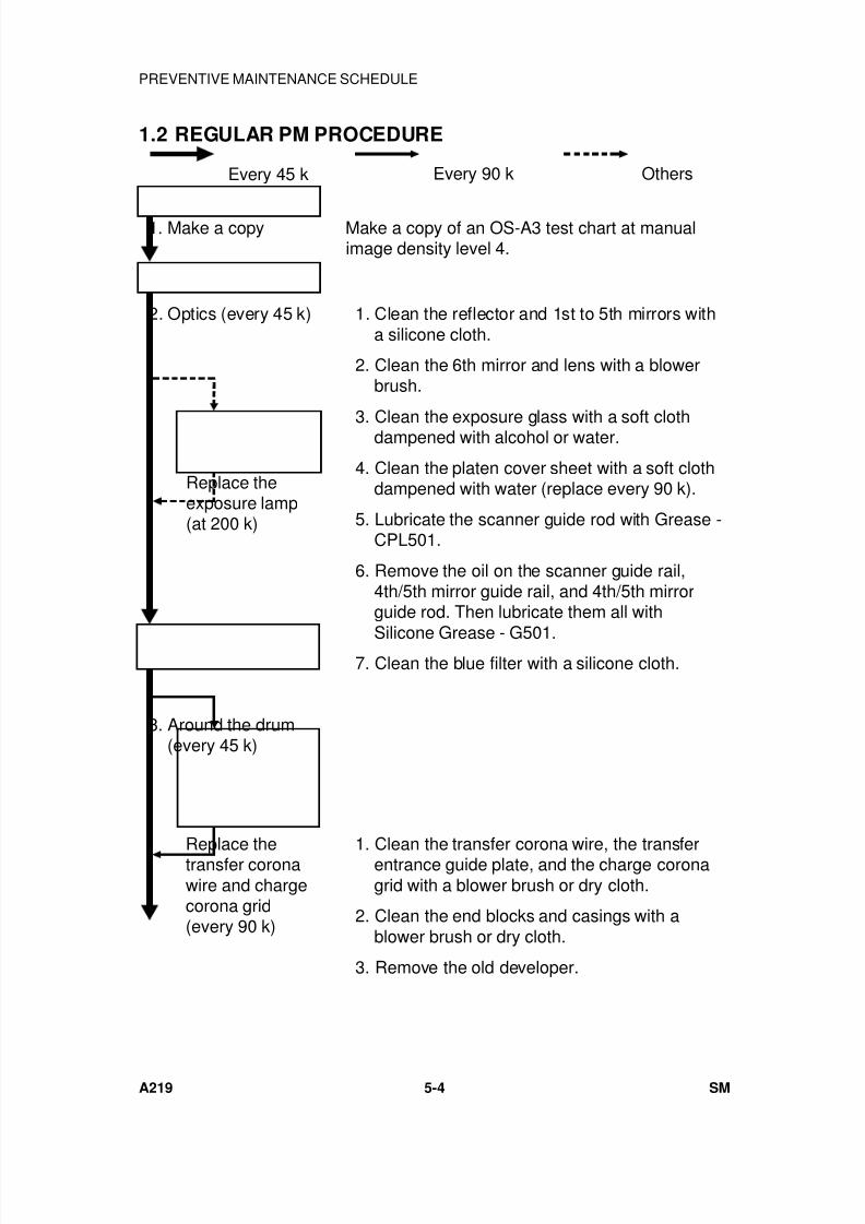
7/18/2019 A219 245 B019 4015 3813 Service
http://slidepdf.com/reader/full/a219-245-b019-4015-3813-service 155/372
1.2 REGULAR PM PROCEDURE
1. Make a copy Make a copy of an OS-A3 test chart at manualimage density level 4.
2. Optics (every 45 k) 1. Clean the reflector and 1st to 5th mirrors witha silicone cloth.
2. Clean the 6th mirror and lens with a blowerbrush.
3. Clean the exposure glass with a soft clothdampened with alcohol or water.
4. Clean the platen cover sheet with a soft clothdampened with water (replace every 90 k).
5. Lubricate the scanner guide rod with Grease -CPL501.
6. Remove the oil on the scanner guide rail,4th/5th mirror guide rail, and 4th/5th mirrorguide rod. Then lubricate them all with
Silicone Grease - G501. 7. Clean the blue filter with a silicone cloth.
3. Around the drum(every 45 k)
1. Clean the transfer corona wire, the transferentrance guide plate, and the charge coronagrid with a blower brush or dry cloth.
2. Clean the end blocks and casings with ablower brush or dry cloth.
3. Remove the old developer.
Replace thetransfer coronawire and chargecorona grid(every 90 k)
Every 45 k Every 90 k Others
Replace theexposure lamp(at 200 k)
PREVENTIVE MAINTENANCE SCHEDULE
A219 5-4 SM
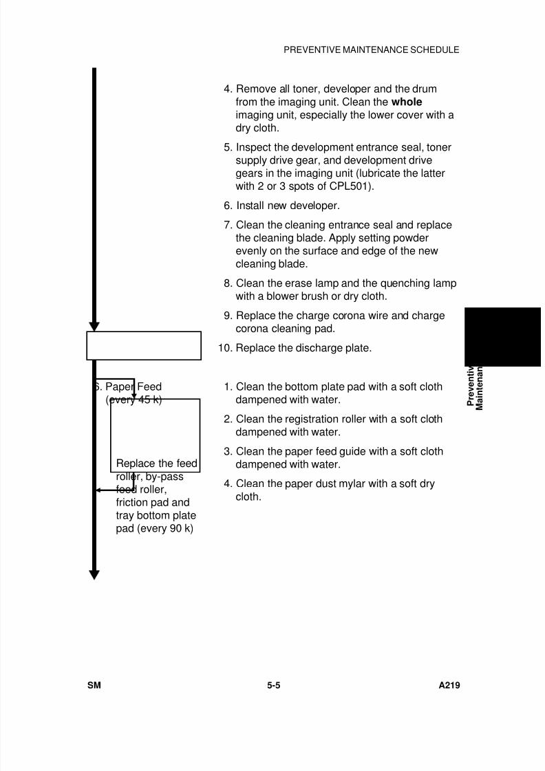
7/18/2019 A219 245 B019 4015 3813 Service
http://slidepdf.com/reader/full/a219-245-b019-4015-3813-service 156/372
4. Remove all toner, developer and the drumfrom the imaging unit. Clean the wholeimaging unit, especially the lower cover with adry cloth.
5. Inspect the development entrance seal, tonersupply drive gear, and development drivegears in the imaging unit (lubricate the latterwith 2 or 3 spots of CPL501).
6. Install new developer.
7. Clean the cleaning entrance seal and replacethe cleaning blade. Apply setting powderevenly on the surface and edge of the new
cleaning blade. 8. Clean the erase lamp and the quenching lamp
with a blower brush or dry cloth.
9. Replace the charge corona wire and chargecorona cleaning pad.
10. Replace the discharge plate.
6. Paper Feed
(every 45 k)
1. Clean the bottom plate pad with a soft cloth
dampened with water. 2. Clean the registration roller with a soft cloth
dampened with water.
3. Clean the paper feed guide with a soft clothdampened with water.
4. Clean the paper dust mylar with a soft drycloth.
Replace the feedroller, by-passfeed roller,friction pad andtray bottom platepad (every 90 k)
P r e v e n t i v e
M a
i n t e n a n c e
PREVENTIVE MAINTENANCE SCHEDULE
SM 5-5 A219
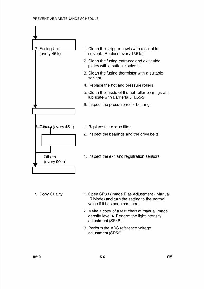
7/18/2019 A219 245 B019 4015 3813 Service
http://slidepdf.com/reader/full/a219-245-b019-4015-3813-service 157/372
7. Fusing Unit(every 45 k) 1. Clean the stripper pawls with a suitablesolvent. (Replace every 135 k.)
2. Clean the fusing entrance and exit guideplates with a suitable solvent.
3. Clean the fusing thermistor with a suitablesolvent.
4. Replace the hot and pressure rollers.
5. Clean the inside of the hot roller bearings andlubricate with Barrierta JFE55/2.
6. Inspect the pressure roller bearings.
8. Others (every 45 k) 1. Replace the ozone filter.
2. Inspect the bearings and the drive belts.
1. Inspect the exit and registration sensors.
9. Copy Quality 1. Open SP33 (Image Bias Adjustment - Manual
ID Mode) and turn the setting to the normalvalue if it has been changed.
2. Make a copy of a test chart at manual imagedensity level 4. Perform the light intensityadjustment (SP48).
3. Perform the ADS reference voltageadjustment (SP56).
Others(every 90 k)
PREVENTIVE MAINTENANCE SCHEDULE
A219 5-6 SM
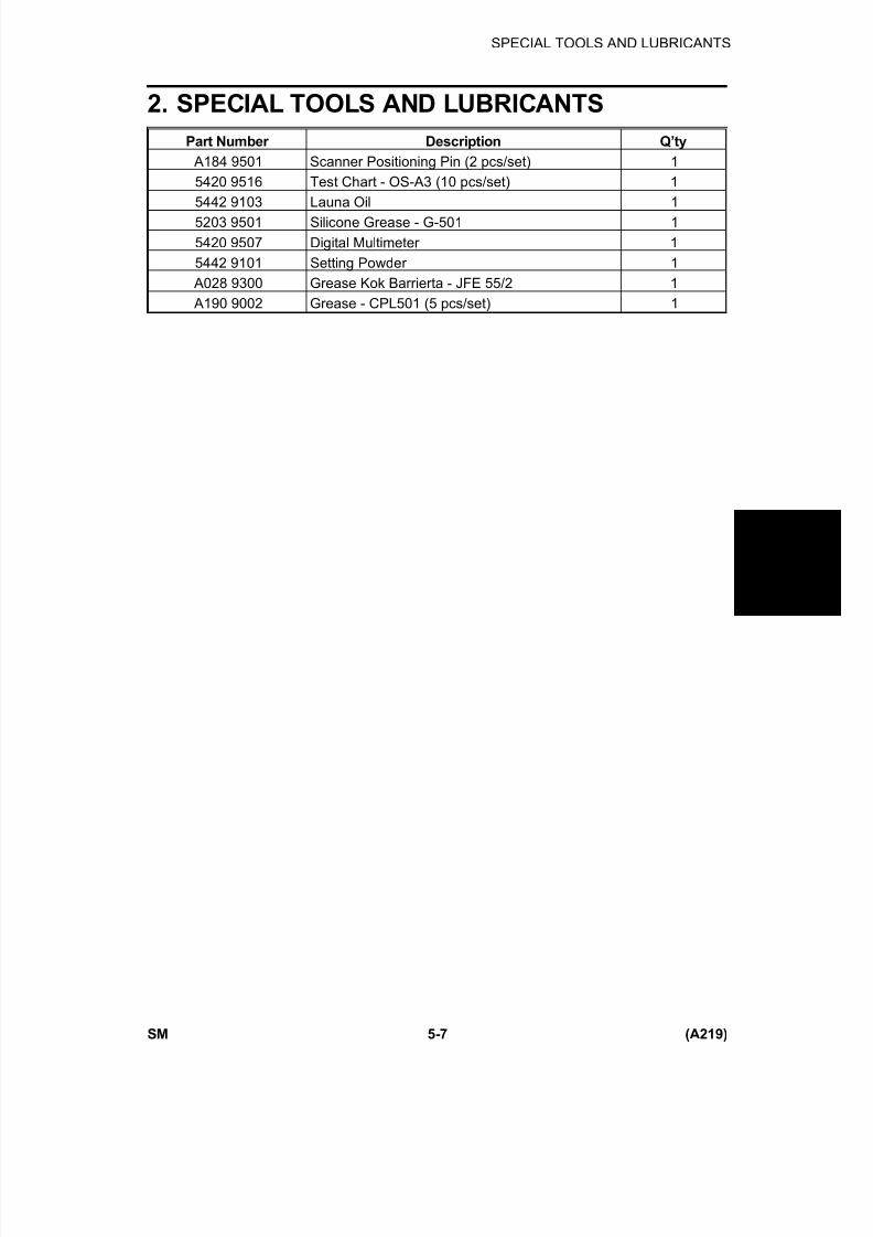
7/18/2019 A219 245 B019 4015 3813 Service
http://slidepdf.com/reader/full/a219-245-b019-4015-3813-service 158/372
2. SPECIAL TOOLS AND LUBRICANTS
Part Number Description Q’ty
A184 9501 Scanner Positioning Pin (2 pcs/set) 1
5420 9516 Test Chart - OS-A3 (10 pcs/set) 1
5442 9103 Launa Oil 1
5203 9501 Silicone Grease - G-501 1
5420 9507 Digital Multimeter 1
5442 9101 Setting Powder 1
A028 9300 Grease Kok Barrierta - JFE 55/2 1
A190 9002 Grease - CPL501 (5 pcs/set) 1
P r e v e n t i v e
M a i n t e n a n c e
SPECIAL TOOLS AND LUBRICANTS
SM 5-7 (A219)

7/18/2019 A219 245 B019 4015 3813 Service
http://slidepdf.com/reader/full/a219-245-b019-4015-3813-service 159/372

7/18/2019 A219 245 B019 4015 3813 Service
http://slidepdf.com/reader/full/a219-245-b019-4015-3813-service 160/372
REPLACEMENTAND
ADJUSTMENT

7/18/2019 A219 245 B019 4015 3813 Service
http://slidepdf.com/reader/full/a219-245-b019-4015-3813-service 161/372
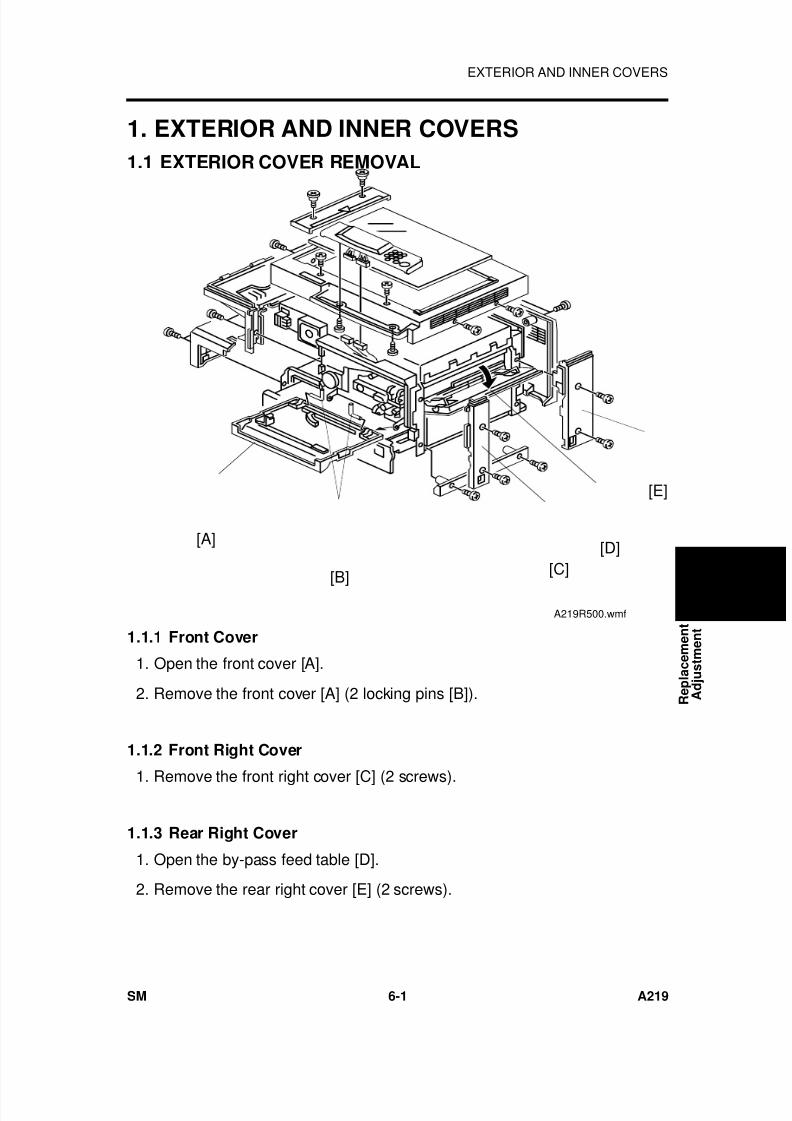
7/18/2019 A219 245 B019 4015 3813 Service
http://slidepdf.com/reader/full/a219-245-b019-4015-3813-service 162/372
1. EXTERIOR AND INNER COVERS
1.1 EXTERIOR COVER REMOVAL
1.1.1 Front Cover
1. Open the front cover [A].
2. Remove the front cover [A] (2 locking pins [B]).
1.1.2 Front Right Cover
1. Remove the front right cover [C] (2 screws).
1.1.3 Rear Right Cover
1. Open the by-pass feed table [D].
2. Remove the rear right cover [E] (2 screws).
[A]
[C]
[E]
[B]
[D]
A219R500.wmf
R e p l a c e m e n t
A d j u s t m e n t
EXTERIOR AND INNER COVERS
SM 6-1 A219
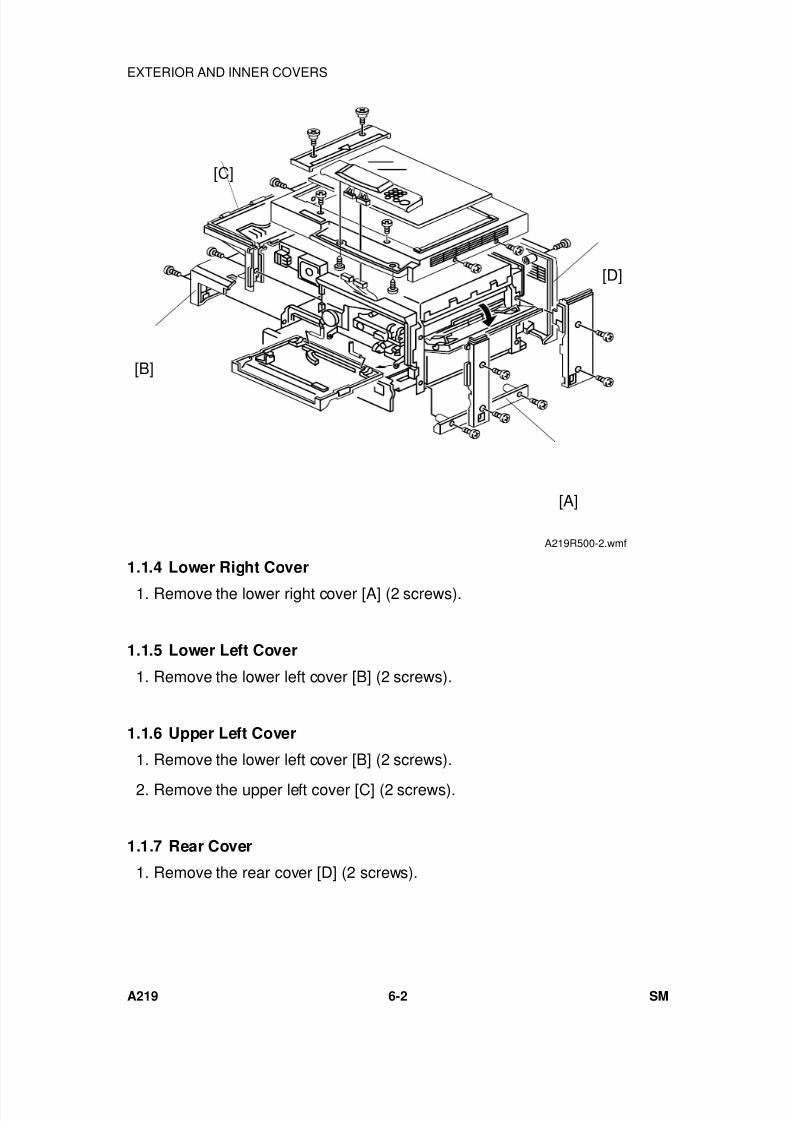
7/18/2019 A219 245 B019 4015 3813 Service
http://slidepdf.com/reader/full/a219-245-b019-4015-3813-service 163/372
1.1.4 Lower Right Cover
1. Remove the lower right cover [A] (2 screws).
1.1.5 Lower Left Cover
1. Remove the lower left cover [B] (2 screws).
1.1.6 Upper Left Cover
1. Remove the lower left cover [B] (2 screws).
2. Remove the upper left cover [C] (2 screws).
1.1.7 Rear Cover
1. Remove the rear cover [D] (2 screws).
[B]
[A]
[C]
[D]
A219R500-2.wmf
EXTERIOR AND INNER COVERS
A219 6-2 SM
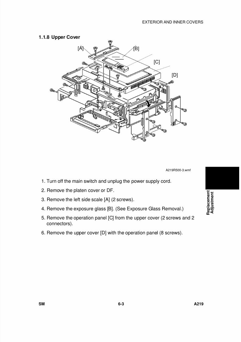
7/18/2019 A219 245 B019 4015 3813 Service
http://slidepdf.com/reader/full/a219-245-b019-4015-3813-service 164/372
1.1.8 Upper Cover
1. Turn off the main switch and unplug the power supply cord.
2. Remove the platen cover or DF.
3. Remove the left side scale [A] (2 screws).
4. Remove the exposure glass [B]. (See Exposure Glass Removal.)
5. Remove the operation panel [C] from the upper cover (2 screws and 2connectors).
6. Remove the upper cover [D] with the operation panel (8 screws).
[B][A]
[D]
[C]
A219R500-3.wmf
R e p l a c e m e n t
A d j u s t m e n t
EXTERIOR AND INNER COVERS
SM 6-3 A219
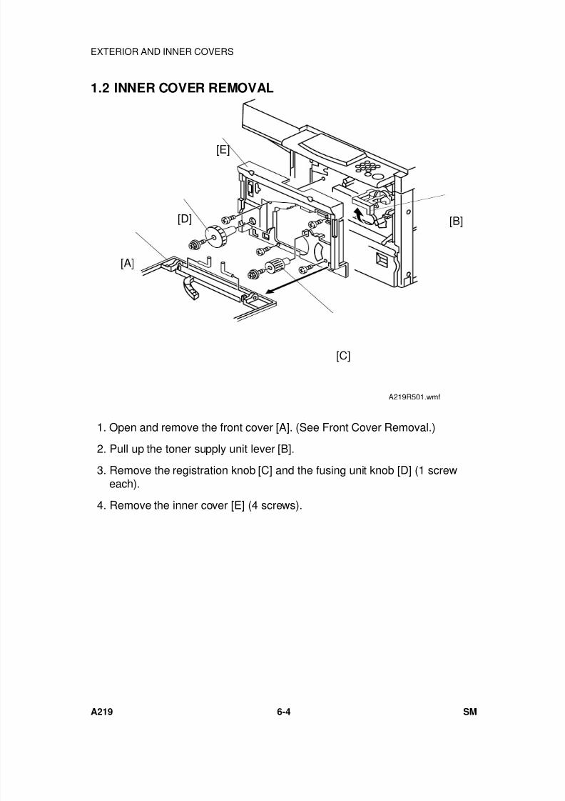
7/18/2019 A219 245 B019 4015 3813 Service
http://slidepdf.com/reader/full/a219-245-b019-4015-3813-service 165/372
1.2 INNER COVER REMOVAL
1. Open and remove the front cover [A]. (See Front Cover Removal.)
2. Pull up the toner supply unit lever [B].
3. Remove the registration knob [C] and the fusing unit knob [D] (1 screweach).
4. Remove the inner cover [E] (4 screws).
[B]
[C]
[A]
[D]
[E]
A219R501.wmf
EXTERIOR AND INNER COVERS
A219 6-4 SM
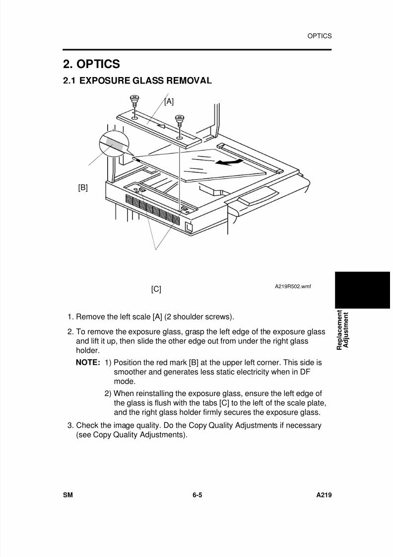
7/18/2019 A219 245 B019 4015 3813 Service
http://slidepdf.com/reader/full/a219-245-b019-4015-3813-service 166/372
2. OPTICS
2.1 EXPOSURE GLASS REMOVAL
1. Remove the left scale [A] (2 shoulder screws).
2. To remove the exposure glass, grasp the left edge of the exposure glassand lift it up, then slide the other edge out from under the right glassholder.
NOTE: 1) Position the red mark [B] at the upper left corner. This side issmoother and generates less static electricity when in DFmode.
2) When reinstalling the exposure glass, ensure the left edge ofthe glass is flush with the tabs [C] to the left of the scale plate,and the right glass holder firmly secures the exposure glass.
3. Check the image quality. Do the Copy Quality Adjustments if necessary(see Copy Quality Adjustments).
[A]
[B]
[C]A219R502.wmf
R e p l a c e m e n t
A d j u s t m e n t
OPTICS
SM 6-5 A219
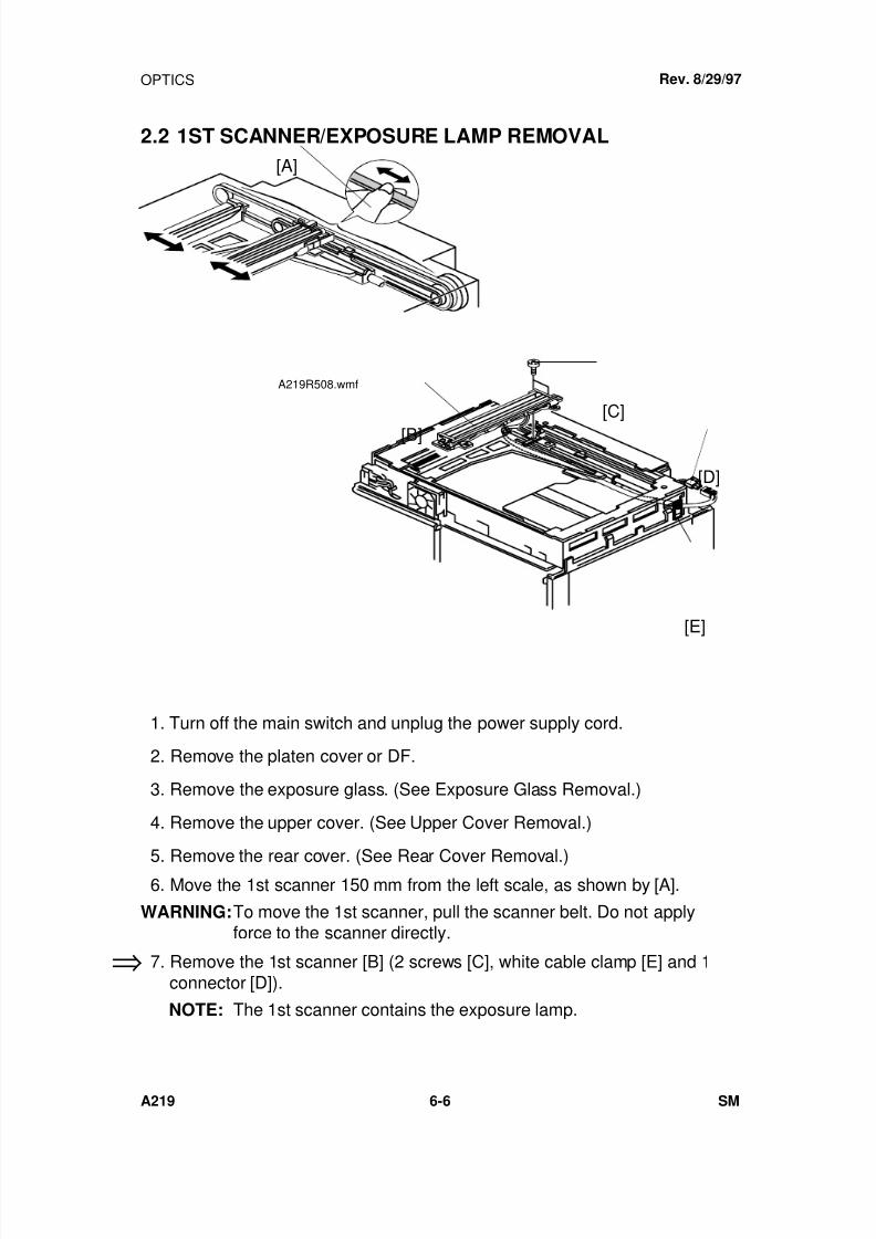
7/18/2019 A219 245 B019 4015 3813 Service
http://slidepdf.com/reader/full/a219-245-b019-4015-3813-service 167/372
2.2 1ST SCANNER/EXPOSURE LAMP REMOVAL
1. Turn off the main switch and unplug the power supply cord.
2. Remove the platen cover or DF.
3. Remove the exposure glass. (See Exposure Glass Removal.)
4. Remove the upper cover. (See Upper Cover Removal.)
5. Remove the rear cover. (See Rear Cover Removal.) 6. Move the 1st scanner 150 mm from the left scale, as shown by [A].
WARNING:To move the 1st scanner, pull the scanner belt. Do not applyforce to the scanner directly.
7. Remove the 1st scanner [B] (2 screws [C], white cable clamp [E] and 1connector [D]).
NOTE: The 1st scanner contains the exposure lamp.
Rev. 8/29/97
⇒
[A]
A219R508.wmf
[C]
[D]
[B]
[E]
OPTICS
A219 6-6 SM
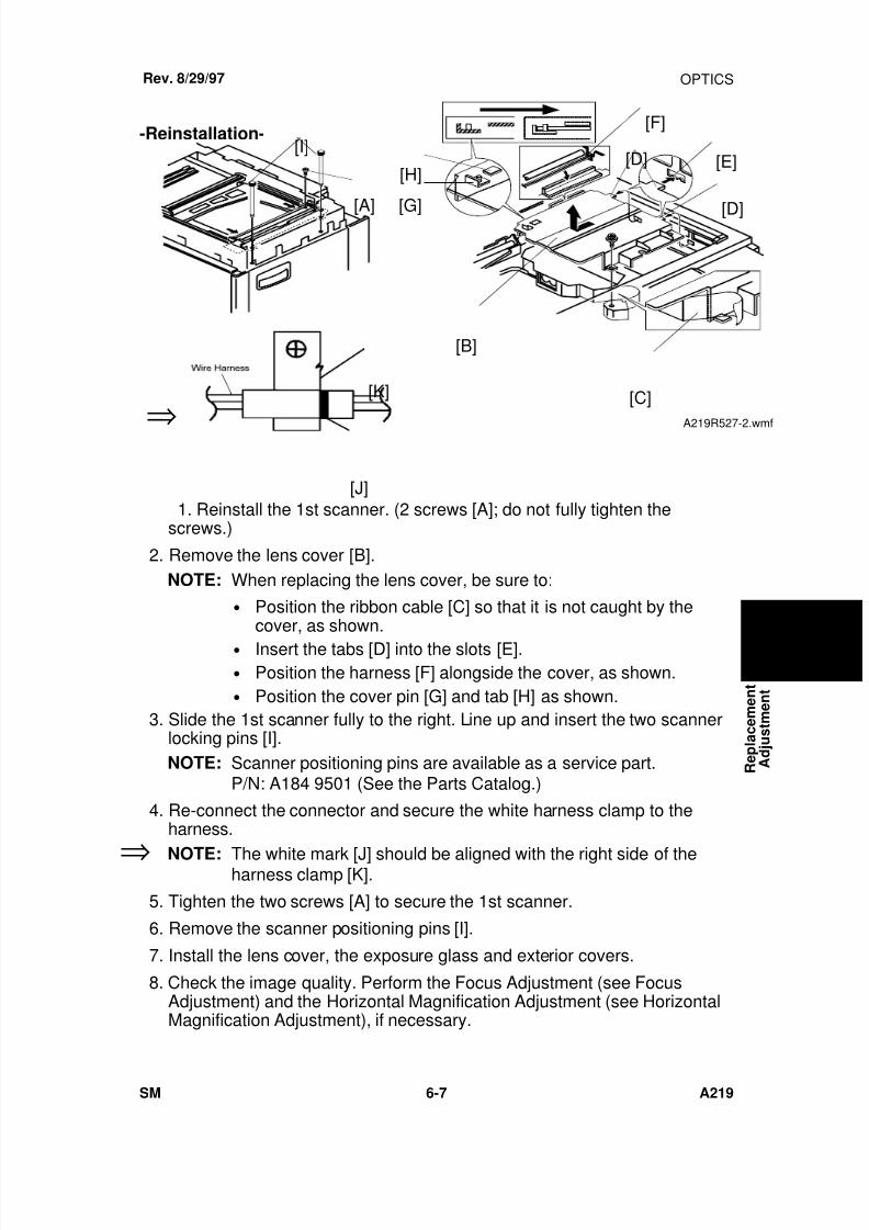
7/18/2019 A219 245 B019 4015 3813 Service
http://slidepdf.com/reader/full/a219-245-b019-4015-3813-service 168/372
-Reinstallation-
1. Reinstall the 1st scanner. (2 screws [A]; do not fully tighten thescrews.)
2. Remove the lens cover [B].NOTE: When replacing the lens cover, be sure to:
• Position the ribbon cable [C] so that it is not caught by thecover, as shown.
• Insert the tabs [D] into the slots [E].• Position the harness [F] alongside the cover, as shown.• Position the cover pin [G] and tab [H] as shown.
3. Slide the 1st scanner fully to the right. Line up and insert the two scannerlocking pins [I].NOTE: Scanner positioning pins are available as a service part.
P/N: A184 9501 (See the Parts Catalog.)
4. Re-connect the connector and secure the white harness clamp to theharness.
NOTE: The white mark [J] should be aligned with the right side of theharness clamp [K].
5. Tighten the two screws [A] to secure the 1st scanner.
6. Remove the scanner positioning pins [I].
7. Install the lens cover, the exposure glass and exterior covers.
8. Check the image quality. Perform the Focus Adjustment (see FocusAdjustment) and the Horizontal Magnification Adjustment (see HorizontalMagnification Adjustment), if necessary.
[B]
⇒
Rev. 8/29/97
[I]
[A]
[F]
[D] [E]
[D]
[C]
[H]
[G]
A219R527-2.wmf
[K]
[J]
⇒
R e p l a c e m e n t
A d j u s t m e n t
OPTICS
SM 6-7 A219
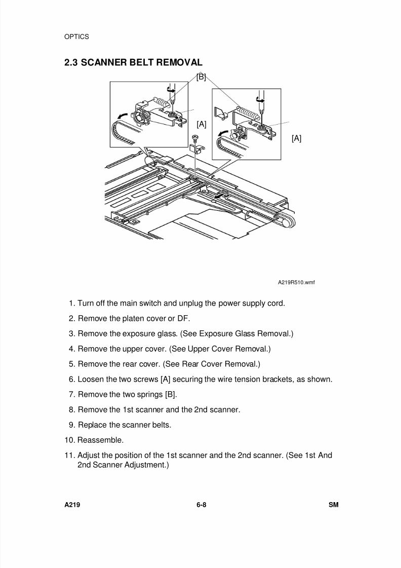
7/18/2019 A219 245 B019 4015 3813 Service
http://slidepdf.com/reader/full/a219-245-b019-4015-3813-service 169/372
2.3 SCANNER BELT REMOVAL
1. Turn off the main switch and unplug the power supply cord.
2. Remove the platen cover or DF.
3. Remove the exposure glass. (See Exposure Glass Removal.)
4. Remove the upper cover. (See Upper Cover Removal.)
5. Remove the rear cover. (See Rear Cover Removal.)
6. Loosen the two screws [A] securing the wire tension brackets, as shown.
7. Remove the two springs [B]. 8. Remove the 1st scanner and the 2nd scanner.
9. Replace the scanner belts.
10. Reassemble.
11. Adjust the position of the 1st scanner and the 2nd scanner. (See 1st And2nd Scanner Adjustment.)
[B]
[A]
[A]
A219R510.wmf
OPTICS
A219 6-8 SM
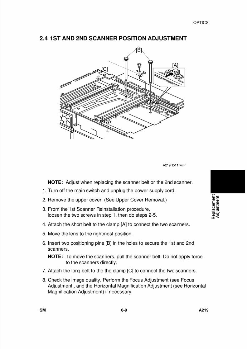
7/18/2019 A219 245 B019 4015 3813 Service
http://slidepdf.com/reader/full/a219-245-b019-4015-3813-service 170/372
2.4 1ST AND 2ND SCANNER POSITION ADJUSTMENT
NOTE: Adjust when replacing the scanner belt or the 2nd scanner. 1. Turn off the main switch and unplug the power supply cord.
2. Remove the upper cover. (See Upper Cover Removal.)
3. From the 1st Scanner Reinstallation procedure,loosen the two screws in step 1, then do steps 2-5.
4. Attach the short belt to the clamp [A] to connect the two scanners.
5. Move the lens to the rightmost position.
6. Insert two positioning pins [B] in the holes to secure the 1st and 2ndscanners.
NOTE: To move the scanners, pull the scanner belt. Do not apply forceto the scanners directly.
7. Attach the long belt to the the clamp [C] to connect the two scanners.
8. Check the image quality. Perform the Focus Adjustment (see FocusAdjustment., and the Horizontal Magnification Adjustment (see HorizontalMagnification Adjustment) if necessary.
[B]
[A][C]
A219R511.wmf
R e p l a c e m e n t
A d j u s t m e n t
OPTICS
SM 6-9 A219
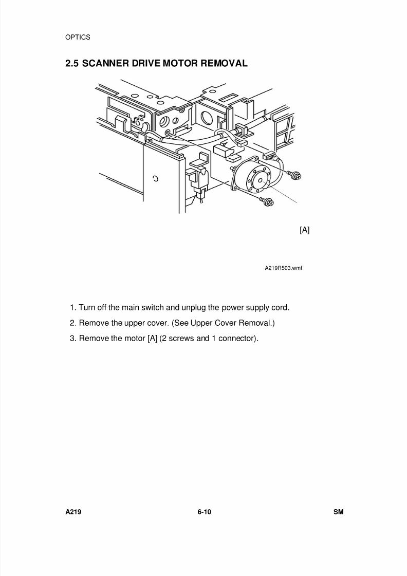
7/18/2019 A219 245 B019 4015 3813 Service
http://slidepdf.com/reader/full/a219-245-b019-4015-3813-service 171/372
2.5 SCANNER DRIVE MOTOR REMOVAL
1. Turn off the main switch and unplug the power supply cord.
2. Remove the upper cover. (See Upper Cover Removal.)
3. Remove the motor [A] (2 screws and 1 connector).
[A]
A219R503.wmf
OPTICS
A219 6-10 SM
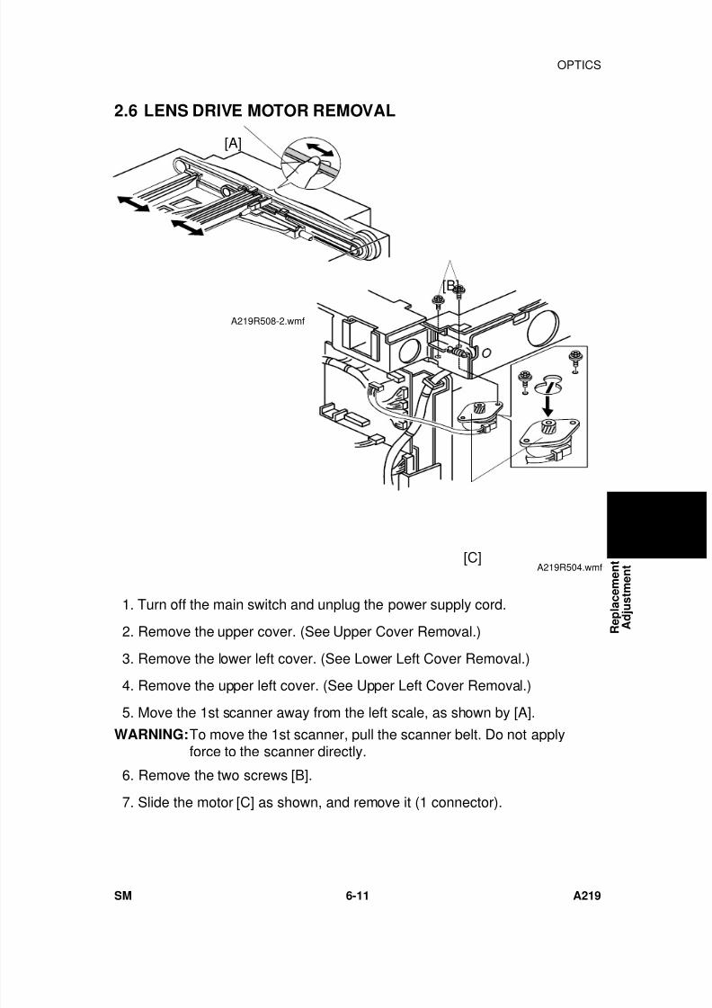
7/18/2019 A219 245 B019 4015 3813 Service
http://slidepdf.com/reader/full/a219-245-b019-4015-3813-service 172/372
2.6 LENS DRIVE MOTOR REMOVAL
1. Turn off the main switch and unplug the power supply cord.
2. Remove the upper cover. (See Upper Cover Removal.)
3. Remove the lower left cover. (See Lower Left Cover Removal.)
4. Remove the upper left cover. (See Upper Left Cover Removal.)
5. Move the 1st scanner away from the left scale, as shown by [A].
WARNING:To move the 1st scanner, pull the scanner belt. Do not applyforce to the scanner directly.
6. Remove the two screws [B].
7. Slide the motor [C] as shown, and remove it (1 connector).
[B]
[C]A219R504.wmf
[A]
A219R508-2.wmf
R e p l a c e m e n t
A d j u s t m e n t
OPTICS
SM 6-11 A219
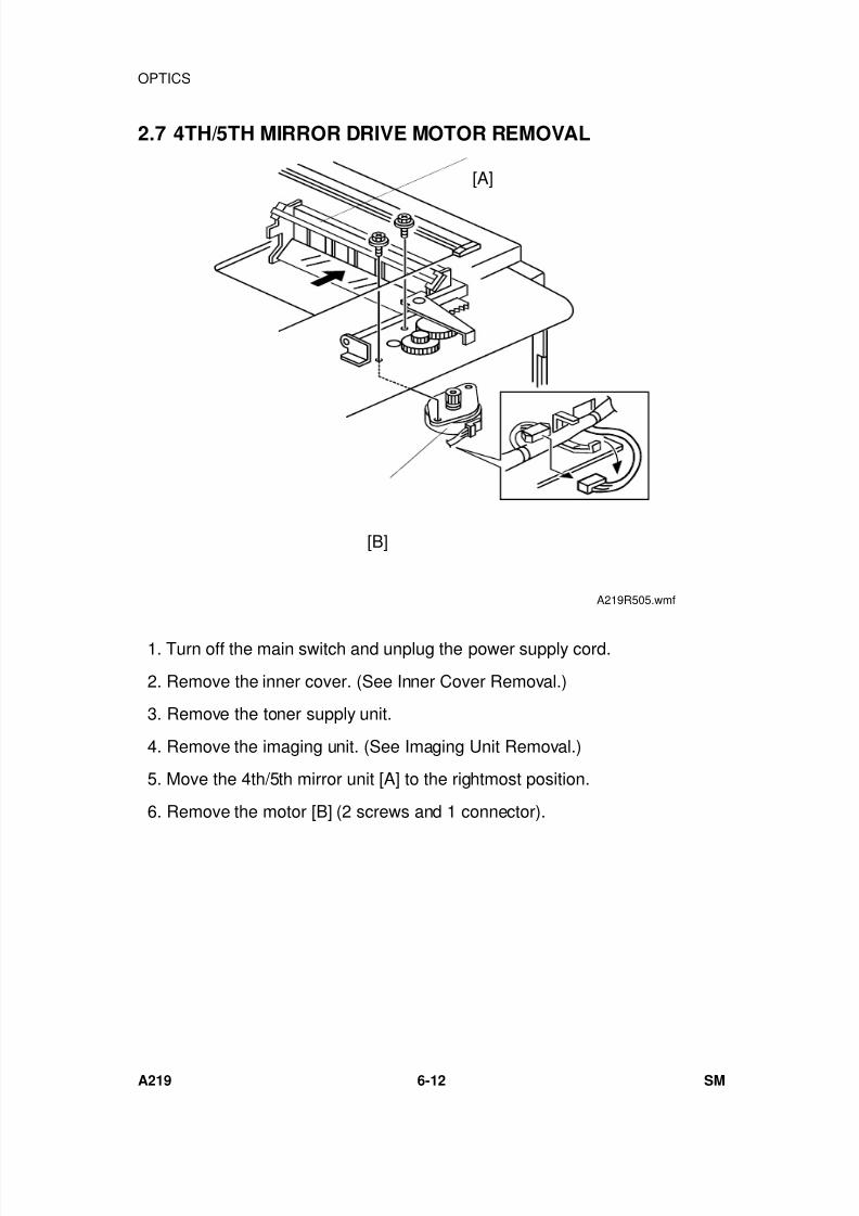
7/18/2019 A219 245 B019 4015 3813 Service
http://slidepdf.com/reader/full/a219-245-b019-4015-3813-service 173/372
2.7 4TH/5TH MIRROR DRIVE MOTOR REMOVAL
1. Turn off the main switch and unplug the power supply cord.
2. Remove the inner cover. (See Inner Cover Removal.)
3. Remove the toner supply unit.
4. Remove the imaging unit. (See Imaging Unit Removal.)
5. Move the 4th/5th mirror unit [A] to the rightmost position.
6. Remove the motor [B] (2 screws and 1 connector).
[A]
[B]
A219R505.wmf
OPTICS
A219 6-12 SM
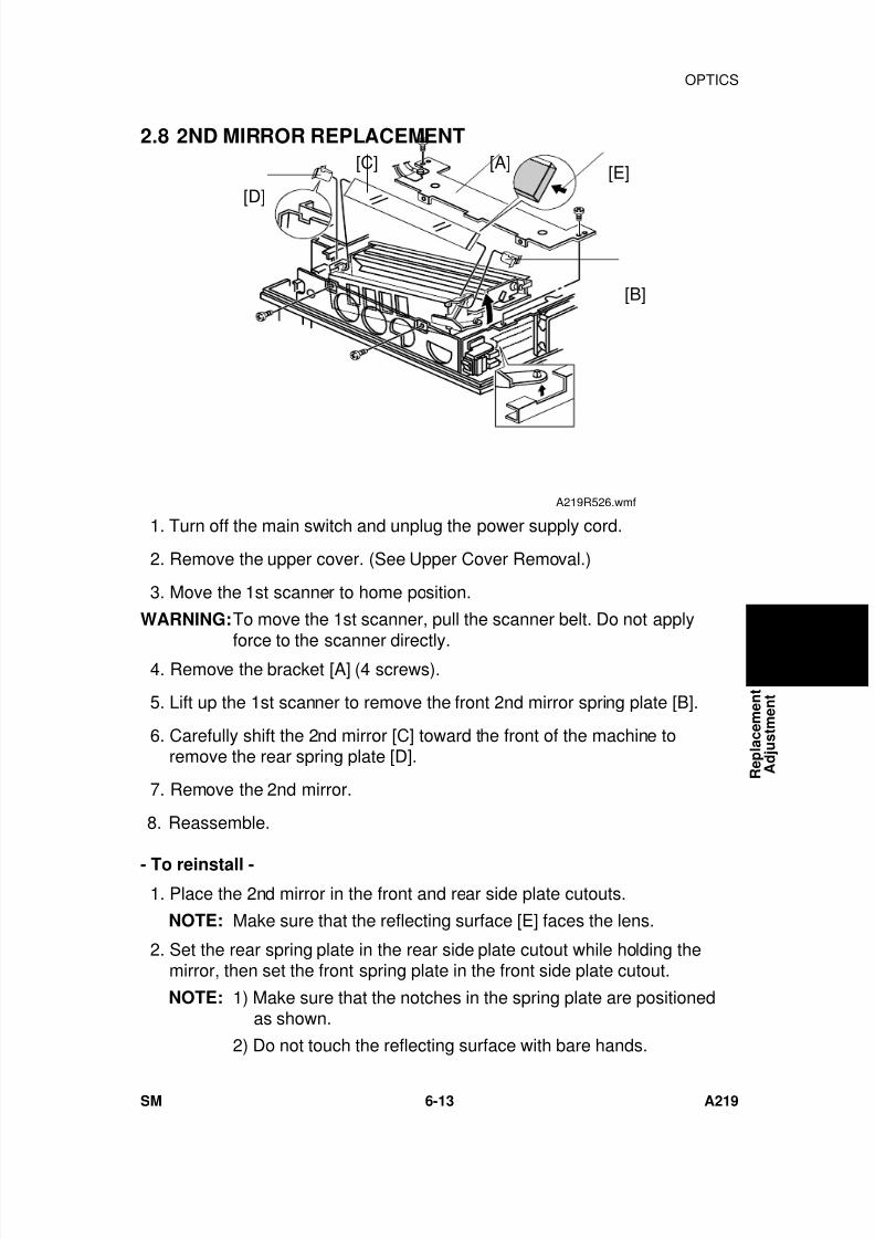
7/18/2019 A219 245 B019 4015 3813 Service
http://slidepdf.com/reader/full/a219-245-b019-4015-3813-service 174/372
2.8 2ND MIRROR REPLACEMENT
1. Turn off the main switch and unplug the power supply cord.
2. Remove the upper cover. (See Upper Cover Removal.)
3. Move the 1st scanner to home position.
WARNING:To move the 1st scanner, pull the scanner belt. Do not apply
force to the scanner directly. 4. Remove the bracket [A] (4 screws).
5. Lift up the 1st scanner to remove the front 2nd mirror spring plate [B].
6. Carefully shift the 2nd mirror [C] toward the front of the machine toremove the rear spring plate [D].
7. Remove the 2nd mirror.
8. Reassemble.
- To reinstall -
1. Place the 2nd mirror in the front and rear side plate cutouts.
NOTE: Make sure that the reflecting surface [E] faces the lens.
2. Set the rear spring plate in the rear side plate cutout while holding themirror, then set the front spring plate in the front side plate cutout.
NOTE: 1) Make sure that the notches in the spring plate are positionedas shown.
2) Do not touch the reflecting surface with bare hands.
[A]
[B]
[C]
[D][E]
A219R526.wmf
R e p l a c e m e n t
A d j u s t m e n t
OPTICS
SM 6-13 A219
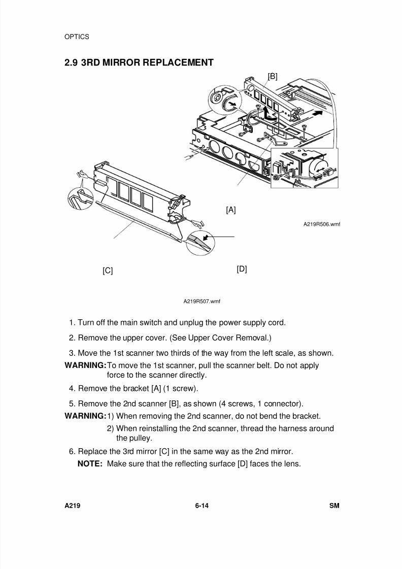
7/18/2019 A219 245 B019 4015 3813 Service
http://slidepdf.com/reader/full/a219-245-b019-4015-3813-service 175/372
2.9 3RD MIRROR REPLACEMENT
1. Turn off the main switch and unplug the power supply cord.
2. Remove the upper cover. (See Upper Cover Removal.)
3. Move the 1st scanner two thirds of the way from the left scale, as shown.
WARNING:To move the 1st scanner, pull the scanner belt. Do not applyforce to the scanner directly.
4. Remove the bracket [A] (1 screw).
5. Remove the 2nd scanner [B], as shown (4 screws, 1 connector).
WARNING:1) When removing the 2nd scanner, do not bend the bracket.
2) When reinstalling the 2nd scanner, thread the harness aroundthe pulley.
6. Replace the 3rd mirror [C] in the same way as the 2nd mirror.
NOTE: Make sure that the reflecting surface [D] faces the lens.
[B]
[A]
A219R506.wmf
[C] [D]
A219R507.wmf
OPTICS
A219 6-14 SM
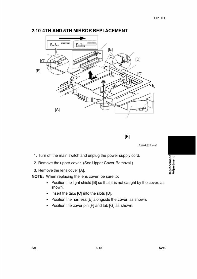
7/18/2019 A219 245 B019 4015 3813 Service
http://slidepdf.com/reader/full/a219-245-b019-4015-3813-service 176/372
2.10 4TH AND 5TH MIRROR REPLACEMENT
1. Turn off the main switch and unplug the power supply cord.
2. Remove the upper cover. (See Upper Cover Removal.)
3. Remove the lens cover [A].
NOTE: When replacing the lens cover, be sure to:
• Position the light shield [B] so that it is not caught by the cover, asshown.
• Insert the tabs [C] into the slots [D].• Position the harness [E] alongside the cover, as shown.
• Position the cover pin [F] and tab [G] as shown.
[D]
[B]
[A]
[E][C]
[C][F]
[G]
A219R527.wmf
R e p l a c e m e n t
A d j u s t m e n t
OPTICS
SM 6-15 A219
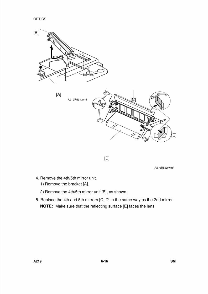
7/18/2019 A219 245 B019 4015 3813 Service
http://slidepdf.com/reader/full/a219-245-b019-4015-3813-service 177/372
4. Remove the 4th/5th mirror unit.1) Remove the bracket [A].
2) Remove the 4th/5th mirror unit [B], as shown.
5. Replace the 4th and 5th mirrors [C, D] in the same way as the 2nd mirror.
NOTE: Make sure that the reflecting surface [E] faces the lens.
[B]
[A]A219R531.wmf [C]
[D]
[E]
A219R532.wmf
OPTICS
A219 6-16 SM
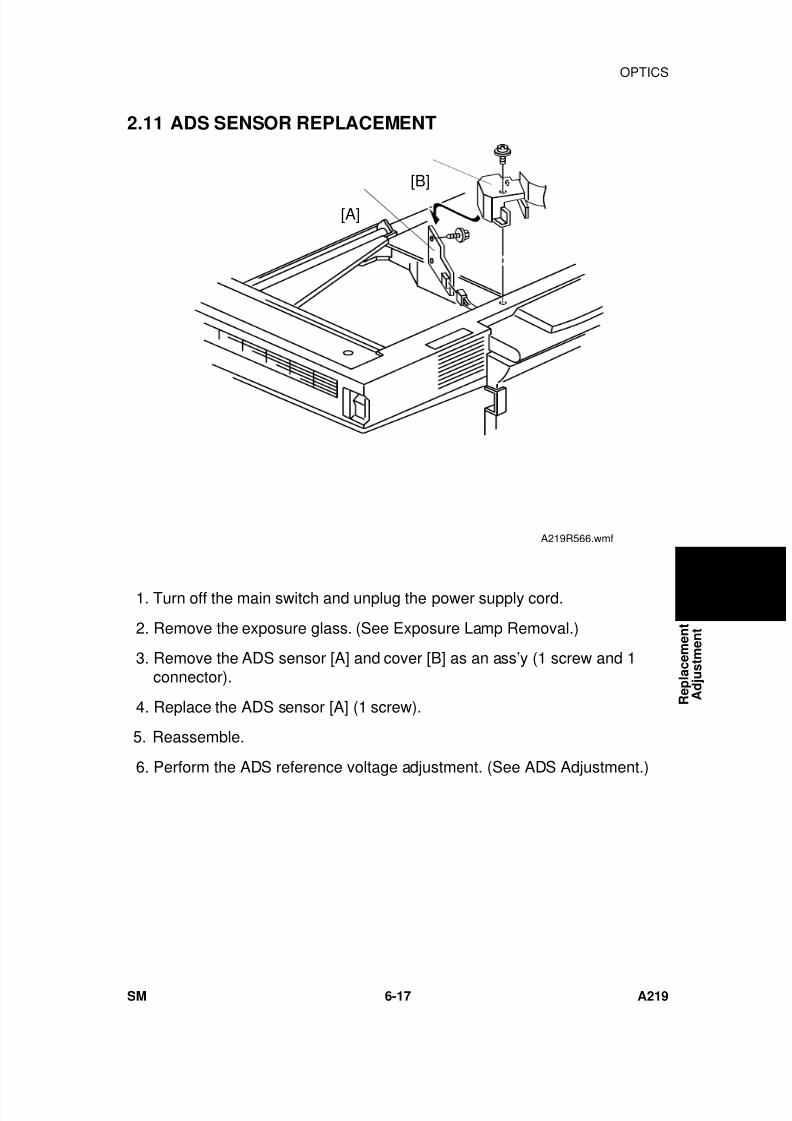
7/18/2019 A219 245 B019 4015 3813 Service
http://slidepdf.com/reader/full/a219-245-b019-4015-3813-service 178/372
2.11 ADS SENSOR REPLACEMENT
1. Turn off the main switch and unplug the power supply cord.
2. Remove the exposure glass. (See Exposure Lamp Removal.)
3. Remove the ADS sensor [A] and cover [B] as an ass’y (1 screw and 1connector).
4. Replace the ADS sensor [A] (1 screw).
5. Reassemble.
6. Perform the ADS reference voltage adjustment. (See ADS Adjustment.)
[B]
[A]
A219R566.wmf
R e p l a c e m e n t
A d j u s t m e n t
OPTICS
SM 6-17 A219
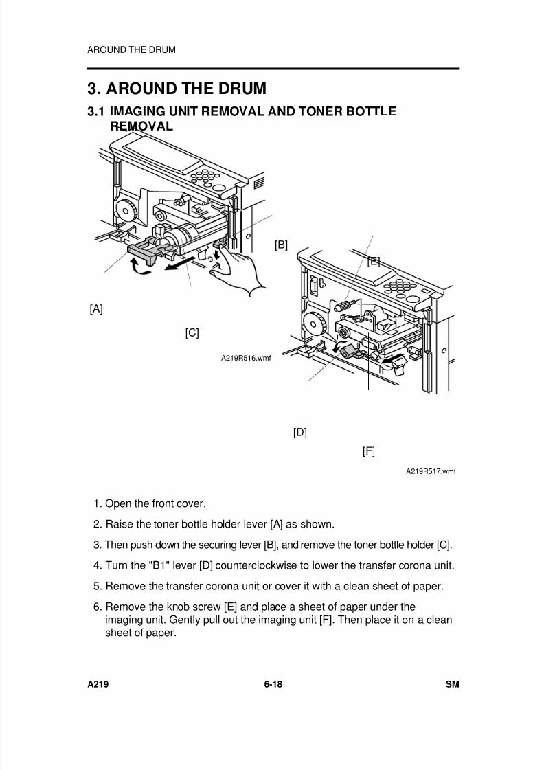
7/18/2019 A219 245 B019 4015 3813 Service
http://slidepdf.com/reader/full/a219-245-b019-4015-3813-service 179/372
3. AROUND THE DRUM
3.1 IMAGING UNIT REMOVAL AND TONER BOTTLEREMOVAL
1. Open the front cover.
2. Raise the toner bottle holder lever [A] as shown.
3. Then push down the securing lever [B], and remove the toner bottle holder [C].
4. Turn the "B1" lever [D] counterclockwise to lower the transfer corona unit.
5. Remove the transfer corona unit or cover it with a clean sheet of paper.
6. Remove the knob screw [E] and place a sheet of paper under theimaging unit. Gently pull out the imaging unit [F]. Then place it on a cleansheet of paper.
[B]
[C]
[A]
A219R516.wmf
[E]
[D]
[F]
A219R517.wmf
AROUND THE DRUM
A219 6-18 SM
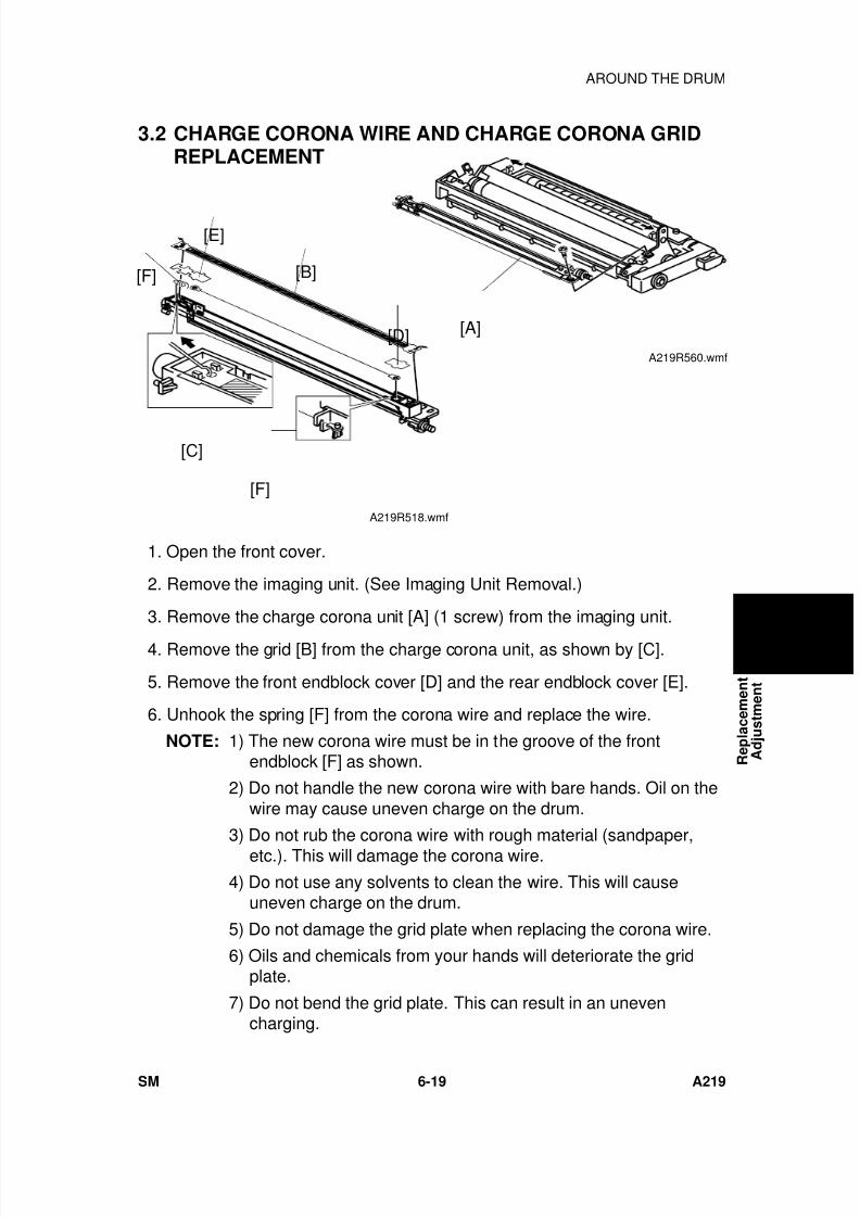
7/18/2019 A219 245 B019 4015 3813 Service
http://slidepdf.com/reader/full/a219-245-b019-4015-3813-service 180/372
3.2 CHARGE CORONA WIRE AND CHARGE CORONA GRIDREPLACEMENT
1. Open the front cover.
2. Remove the imaging unit. (See Imaging Unit Removal.)
3. Remove the charge corona unit [A] (1 screw) from the imaging unit.
4. Remove the grid [B] from the charge corona unit, as shown by [C].
5. Remove the front endblock cover [D] and the rear endblock cover [E].
6. Unhook the spring [F] from the corona wire and replace the wire.
NOTE: 1) The new corona wire must be in the groove of the frontendblock [F] as shown.
2) Do not handle the new corona wire with bare hands. Oil on thewire may cause uneven charge on the drum.
3) Do not rub the corona wire with rough material (sandpaper,etc.). This will damage the corona wire.
4) Do not use any solvents to clean the wire. This will causeuneven charge on the drum.
5) Do not damage the grid plate when replacing the corona wire.
6) Oils and chemicals from your hands will deteriorate the gridplate.
7) Do not bend the grid plate. This can result in an unevencharging.
[E]
[B]
[F]
[C]
[D]
[F]
A219R518.wmf
[A]
A219R560.wmf
R e p l a c e m e n t
A d j u s t m e n t
AROUND THE DRUM
SM 6-19 A219
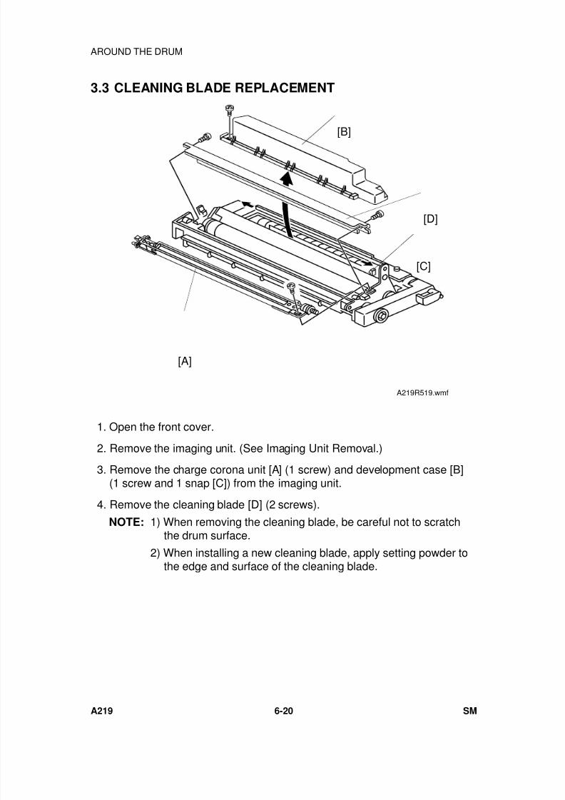
7/18/2019 A219 245 B019 4015 3813 Service
http://slidepdf.com/reader/full/a219-245-b019-4015-3813-service 181/372
3.3 CLEANING BLADE REPLACEMENT
1. Open the front cover.
2. Remove the imaging unit. (See Imaging Unit Removal.)
3. Remove the charge corona unit [A] (1 screw) and development case [B](1 screw and 1 snap [C]) from the imaging unit.
4. Remove the cleaning blade [D] (2 screws).
NOTE: 1) When removing the cleaning blade, be careful not to scratchthe drum surface.
2) When installing a new cleaning blade, apply setting powder tothe edge and surface of the cleaning blade.
[B]
[D]
[A]
[C]
A219R519.wmf
AROUND THE DRUM
A219 6-20 SM
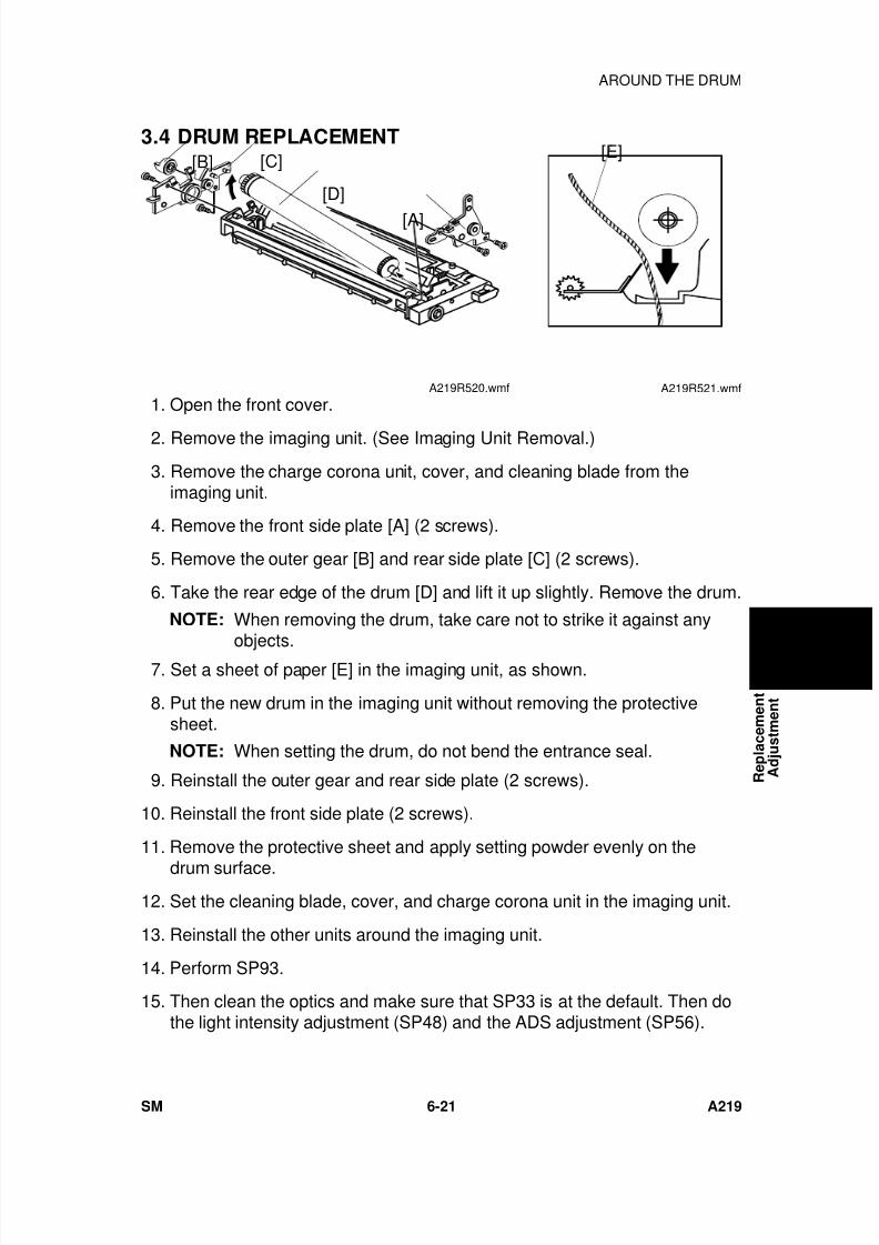
7/18/2019 A219 245 B019 4015 3813 Service
http://slidepdf.com/reader/full/a219-245-b019-4015-3813-service 182/372
3.4 DRUM REPLACEMENT
1. Open the front cover.
2. Remove the imaging unit. (See Imaging Unit Removal.)
3. Remove the charge corona unit, cover, and cleaning blade from theimaging unit.
4. Remove the front side plate [A] (2 screws).
5. Remove the outer gear [B] and rear side plate [C] (2 screws).
6. Take the rear edge of the drum [D] and lift it up slightly. Remove the drum.
NOTE: When removing the drum, take care not to strike it against any
objects. 7. Set a sheet of paper [E] in the imaging unit, as shown.
8. Put the new drum in the imaging unit without removing the protectivesheet.
NOTE: When setting the drum, do not bend the entrance seal.
9. Reinstall the outer gear and rear side plate (2 screws).
10. Reinstall the front side plate (2 screws).
11. Remove the protective sheet and apply setting powder evenly on the
drum surface.
12. Set the cleaning blade, cover, and charge corona unit in the imaging unit.
13. Reinstall the other units around the imaging unit.
14. Perform SP93.
15. Then clean the optics and make sure that SP33 is at the default. Then dothe light intensity adjustment (SP48) and the ADS adjustment (SP56).
[B] [C]
[D]
[A]
A219R520.wmf
[E]
A219R521.wmf
R e p l a c e m e n t
A d j u s t m e n t
AROUND THE DRUM
SM 6-21 A219
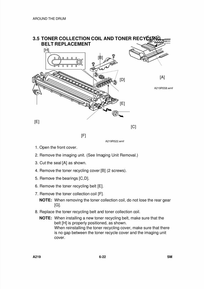
7/18/2019 A219 245 B019 4015 3813 Service
http://slidepdf.com/reader/full/a219-245-b019-4015-3813-service 183/372
3.5 TONER COLLECTION COIL AND TONER RECYCLINGBELT REPLACEMENT
1. Open the front cover.
2. Remove the imaging unit. (See Imaging Unit Removal.)
3. Cut the seal [A] as shown.
4. Remove the toner recycling cover [B] (2 screws).
5. Remove the bearings [C,D].
6. Remove the toner recycling belt [E].
7. Remove the toner collection coil [F].
NOTE: When removing the toner collection coil, do not lose the rear gear[G].
8. Replace the toner recycling belt and toner collection coil.
NOTE: When installing a new toner recycling belt, make sure that thebelt [H] is properly positioned, as shown.When reinstalling the toner recycling cover, make sure that thereis no gap between the toner recycle cover and the imaging unitcover.
[B][H]
[E]
[F]
[C]
[E]
[D]
A219R522.wmf
[A]
A219R558.wmf
AROUND THE DRUM
A219 6-22 SM
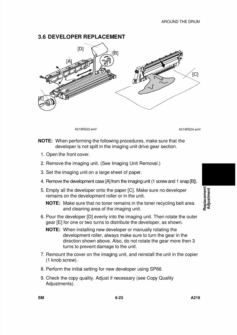
7/18/2019 A219 245 B019 4015 3813 Service
http://slidepdf.com/reader/full/a219-245-b019-4015-3813-service 184/372
3.6 DEVELOPER REPLACEMENT
NOTE: When performing the following procedures, make sure that thedeveloper is not spilt in the imaging unit drive gear section.
1. Open the front cover.
2. Remove the imaging unit. (See Imaging Unit Removal.)
3. Set the imaging unit on a large sheet of paper. 4. Remove the development case [A] from the imaging unit (1 screw and 1 snap [B]).
5. Empty all the developer onto the paper [C]. Make sure no developerremains on the development roller or in the unit.
NOTE: Make sure that no toner remains in the toner recycling belt areaand cleaning area of the imaging unit.
6. Pour the developer [D] evenly into the imaging unit. Then rotate the outergear [E] for one or two turns to distribute the developer, as shown.
NOTE: When installing new developer or manually rotating thedevelopment roller, always make sure to turn the gear in thedirection shown above. Also, do not rotate the gear more then 3turns to prevent damage to the unit.
7. Remount the cover on the imaging unit, and reinstall the unit in the copier(1 knob screw).
8. Perform the initial setting for new developer using SP66.
9. Check the copy quality. Adjust if necessary (see Copy QualityAdjustments).
[B][D]
[A]
[E]
A219R523.wmf
[C]
A219R524.wmf
R e p l a c e m e n t
A d j u s t m e n t
AROUND THE DRUM
SM 6-23 A219
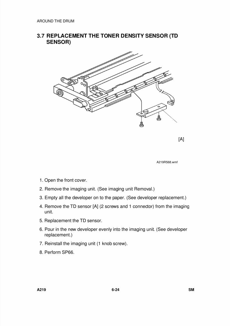
7/18/2019 A219 245 B019 4015 3813 Service
http://slidepdf.com/reader/full/a219-245-b019-4015-3813-service 185/372
3.7 REPLACEMENT THE TONER DENSITY SENSOR (TDSENSOR)
1. Open the front cover.
2. Remove the imaging unit. (See imaging unit Removal.)
3. Empty all the developer on to the paper. (See developer replacement.)
4. Remove the TD sensor [A] (2 screws and 1 connector) from the imagingunit.
5. Replacement the TD sensor.
6. Pour in the new developer evenly into the imaging unit. (See developerreplacement.)
7. Reinstall the imaging unit (1 knob screw).
8. Perform SP66.
[A]
A219R568.wmf
AROUND THE DRUM
A219 6-24 SM
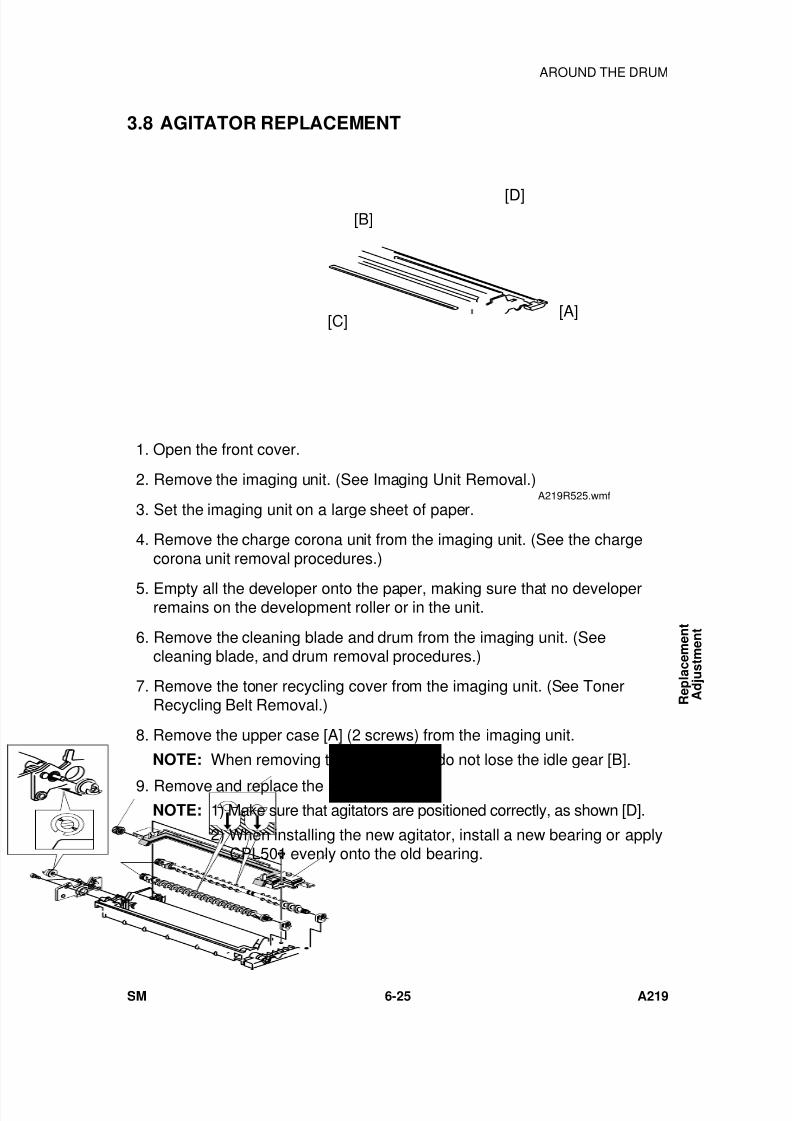
7/18/2019 A219 245 B019 4015 3813 Service
http://slidepdf.com/reader/full/a219-245-b019-4015-3813-service 186/372
3.8 AGITATOR REPLACEMENT
1. Open the front cover.
2. Remove the imaging unit. (See Imaging Unit Removal.)
3. Set the imaging unit on a large sheet of paper.
4. Remove the charge corona unit from the imaging unit. (See the chargecorona unit removal procedures.)
5. Empty all the developer onto the paper, making sure that no developerremains on the development roller or in the unit.
6. Remove the cleaning blade and drum from the imaging unit. (Seecleaning blade, and drum removal procedures.)
7. Remove the toner recycling cover from the imaging unit. (See TonerRecycling Belt Removal.)
8. Remove the upper case [A] (2 screws) from the imaging unit.
NOTE: When removing the upper case, do not lose the idle gear [B].
9. Remove and replace the agitators [C].NOTE: 1) Make sure that agitators are positioned correctly, as shown [D].
2) When installing the new agitator, install a new bearing or applyCPL501 evenly onto the old bearing.
[A]
[B]
[C]
[D]
A219R525.wmf
R e p l a c e m e n t
A d j u s t m e n t
AROUND THE DRUM
SM 6-25 A219
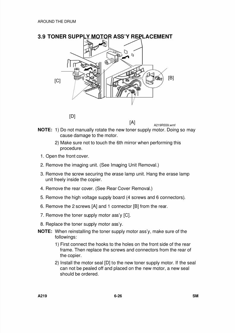
7/18/2019 A219 245 B019 4015 3813 Service
http://slidepdf.com/reader/full/a219-245-b019-4015-3813-service 187/372
3.9 TONER SUPPLY MOTOR ASS’Y REPLACEMENT
NOTE: 1) Do not manually rotate the new toner supply motor. Doing so maycause damage to the motor.
2) Make sure not to touch the 6th mirror when performing thisprocedure.
1. Open the front cover.
2. Remove the imaging unit. (See Imaging Unit Removal.)
3. Remove the screw securing the erase lamp unit. Hang the erase lampunit freely inside the copier.
4. Remove the rear cover. (See Rear Cover Removal.)
5. Remove the high voltage supply board (4 screws and 6 connectors).
6. Remove the 2 screws [A] and 1 connector [B] from the rear.
7. Remove the toner supply motor ass’y [C].
8. Replace the toner supply motor ass’y.
NOTE: When reinstalling the toner supply motor ass’y, make sure of thefollowings:
1) First connect the hooks to the holes on the front side of the rearframe. Then replace the screws and connectors from the rear ofthe copier.
2) Install the motor seal [D] to the new toner supply motor. If the sealcan not be pealed off and placed on the new motor, a new sealshould be ordered.
[B]
[A]
[C]
[D]A219R559.wmf
AROUND THE DRUM
A219 6-26 SM
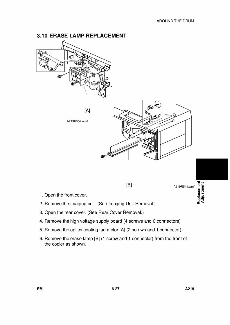
7/18/2019 A219 245 B019 4015 3813 Service
http://slidepdf.com/reader/full/a219-245-b019-4015-3813-service 188/372
3.10 ERASE LAMP REPLACEMENT
1. Open the front cover.
2. Remove the imaging unit. (See Imaging Unit Removal.)
3. Open the rear cover. (See Rear Cover Removal.)
4. Remove the high voltage supply board (4 screws and 6 connectors).
5. Remove the optics cooling fan motor [A] (2 screws and 1 connector).
6. Remove the erase lamp [B] (1 screw and 1 connector) from the front ofthe copier as shown.
[B] A219R541.wmf
[A]A219R557.wmf
R e p l a c e m e n t
A d j u s t m e n t
AROUND THE DRUM
SM 6-27 A219
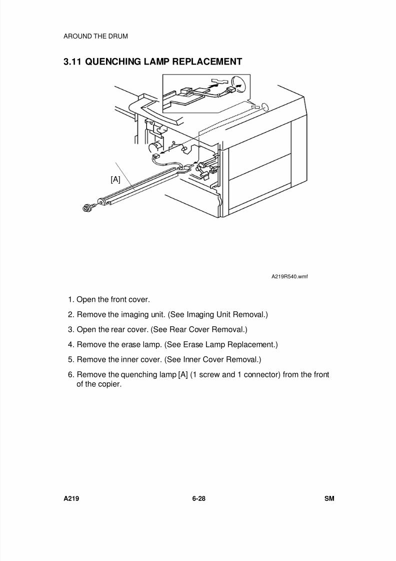
7/18/2019 A219 245 B019 4015 3813 Service
http://slidepdf.com/reader/full/a219-245-b019-4015-3813-service 189/372
3.11 QUENCHING LAMP REPLACEMENT
1. Open the front cover.
2. Remove the imaging unit. (See Imaging Unit Removal.)
3. Open the rear cover. (See Rear Cover Removal.)
4. Remove the erase lamp. (See Erase Lamp Replacement.)
5. Remove the inner cover. (See Inner Cover Removal.)
6. Remove the quenching lamp [A] (1 screw and 1 connector) from the frontof the copier.
[A]
A219R540.wmf
AROUND THE DRUM
A219 6-28 SM
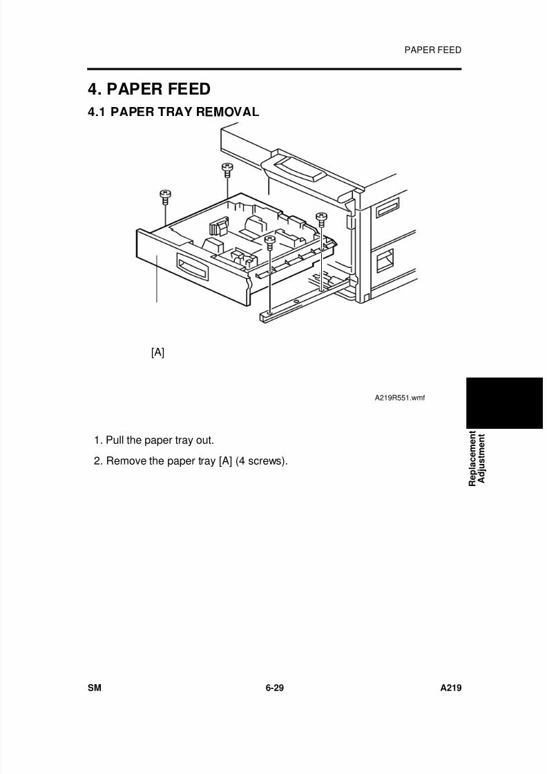
7/18/2019 A219 245 B019 4015 3813 Service
http://slidepdf.com/reader/full/a219-245-b019-4015-3813-service 190/372
4. PAPER FEED
4.1 PAPER TRAY REMOVAL
1. Pull the paper tray out.
2. Remove the paper tray [A] (4 screws).
[A]
A219R551.wmf
R e p l a c e m e n t
A d j u s t m e n t
PAPER FEED
SM 6-29 A219
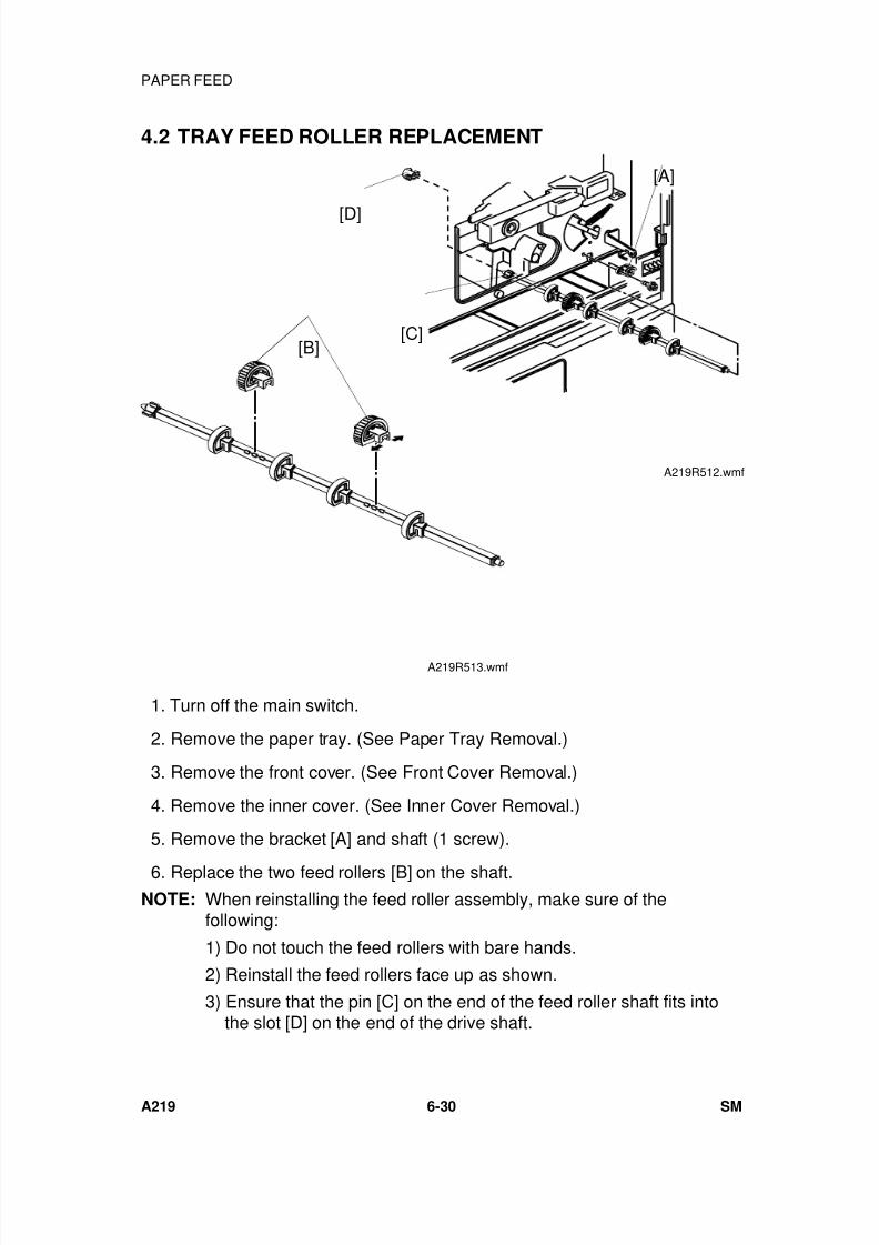
7/18/2019 A219 245 B019 4015 3813 Service
http://slidepdf.com/reader/full/a219-245-b019-4015-3813-service 191/372
4.2 TRAY FEED ROLLER REPLACEMENT
1. Turn off the main switch.
2. Remove the paper tray. (See Paper Tray Removal.)
3. Remove the front cover. (See Front Cover Removal.)
4. Remove the inner cover. (See Inner Cover Removal.)
5. Remove the bracket [A] and shaft (1 screw).
6. Replace the two feed rollers [B] on the shaft.NOTE: When reinstalling the feed roller assembly, make sure of the
following:
1) Do not touch the feed rollers with bare hands.
2) Reinstall the feed rollers face up as shown.
3) Ensure that the pin [C] on the end of the feed roller shaft fits intothe slot [D] on the end of the drive shaft.
A219R512.wmf
[B]
[D]
[A]
[C]
A219R513.wmf
PAPER FEED
A219 6-30 SM
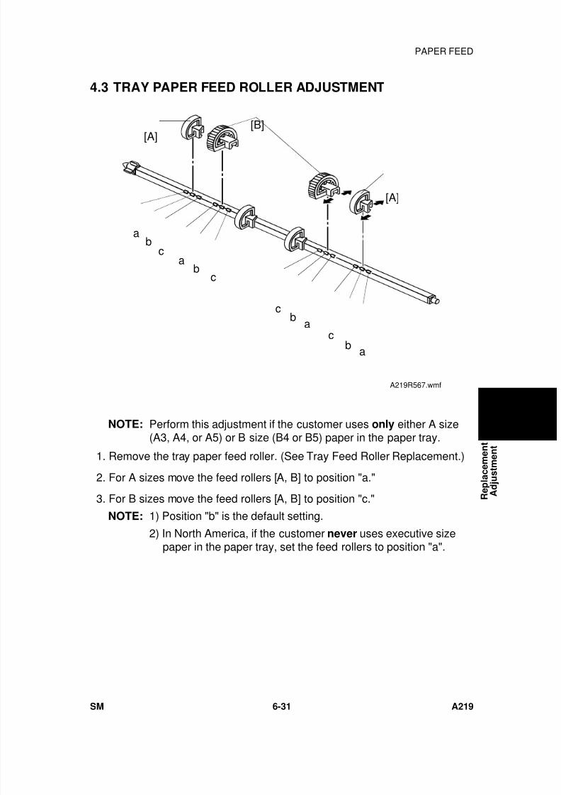
7/18/2019 A219 245 B019 4015 3813 Service
http://slidepdf.com/reader/full/a219-245-b019-4015-3813-service 192/372
4.3 TRAY PAPER FEED ROLLER ADJUSTMENT
NOTE: Perform this adjustment if the customer uses only either A size(A3, A4, or A5) or B size (B4 or B5) paper in the paper tray.
1. Remove the tray paper feed roller. (See Tray Feed Roller Replacement.)
2. For A sizes move the feed rollers [A, B] to position "a."
3. For B sizes move the feed rollers [A, B] to position "c."
NOTE: 1) Position "b" is the default setting.
2) In North America, if the customer never uses executive size
paper in the paper tray, set the feed rollers to position "a".
ab
c
[A]
[B]
[A]
ab
c
cb
ac
b a
A219R567.wmf
R e p l a c e m e n t
A d j u s t m e n t
PAPER FEED
SM 6-31 A219
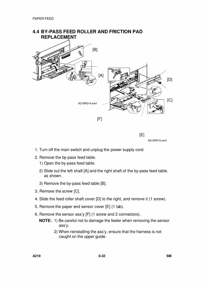
7/18/2019 A219 245 B019 4015 3813 Service
http://slidepdf.com/reader/full/a219-245-b019-4015-3813-service 193/372
4.4 BY-PASS FEED ROLLER AND FRICTION PADREPLACEMENT
1. Turn off the main switch and unplug the power supply cord. 2. Remove the by-pass feed table.
1) Open the by-pass feed table.
2) Slide out the left shaft [A] and the right shaft of the by-pass feed table,as shown.
3) Remove the by-pass feed table [B].
3. Remove the screw [C].
4. Slide the feed roller shaft cover [D] to the right, and remove it (1 screw). 5. Remove the paper end sensor cover [E] (1 tab).
6. Remove the sensor ass’y [F] (1 screw and 2 connectors).
NOTE: 1) Be careful not to damage the feeler when removing the sensorass’y.
2) When reinstalling the ass’y, ensure that the harness is notcaught on the upper guide.
[A]
[B]
A219R514.wmf [C]
[D]
[E]
[F]
A219R515.wmf
PAPER FEED
A219 6-32 SM
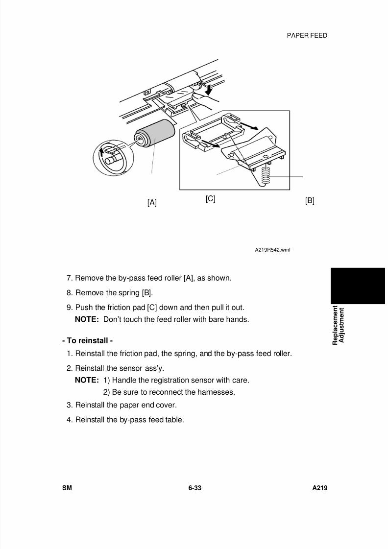
7/18/2019 A219 245 B019 4015 3813 Service
http://slidepdf.com/reader/full/a219-245-b019-4015-3813-service 194/372
7. Remove the by-pass feed roller [A], as shown.
8. Remove the spring [B].
9. Push the friction pad [C] down and then pull it out.
NOTE: Don’t touch the feed roller with bare hands.
- To reinstall -
1. Reinstall the friction pad, the spring, and the by-pass feed roller.
2. Reinstall the sensor ass’y.
NOTE: 1) Handle the registration sensor with care.2) Be sure to reconnect the harnesses.
3. Reinstall the paper end cover.
4. Reinstall the by-pass feed table.
[A] [B][C]
A219R542.wmf
R e p l a c e m e n t
A d j u s t m e n t
PAPER FEED
SM 6-33 A219
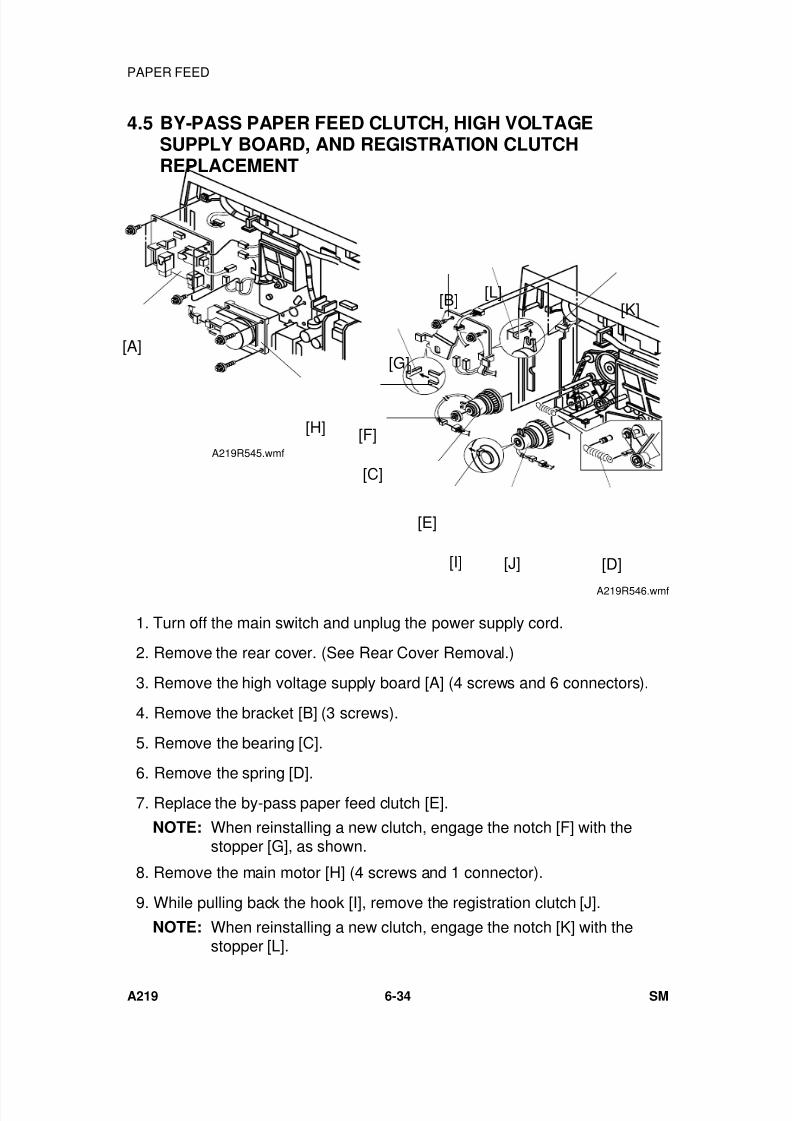
7/18/2019 A219 245 B019 4015 3813 Service
http://slidepdf.com/reader/full/a219-245-b019-4015-3813-service 195/372
4.5 BY-PASS PAPER FEED CLUTCH, HIGH VOLTAGESUPPLY BOARD, AND REGISTRATION CLUTCHREPLACEMENT
1. Turn off the main switch and unplug the power supply cord.
2. Remove the rear cover. (See Rear Cover Removal.)
3. Remove the high voltage supply board [A] (4 screws and 6 connectors).
4. Remove the bracket [B] (3 screws).
5. Remove the bearing [C].
6. Remove the spring [D]. 7. Replace the by-pass paper feed clutch [E].
NOTE: When reinstalling a new clutch, engage the notch [F] with thestopper [G], as shown.
8. Remove the main motor [H] (4 screws and 1 connector).
9. While pulling back the hook [I], remove the registration clutch [J].
NOTE: When reinstalling a new clutch, engage the notch [K] with thestopper [L].
[A]
[H]
A219R545.wmf
[B] [L][K]
[F]
[C]
[E]
[D]
[G]
[J][I]
A219R546.wmf
PAPER FEED
A219 6-34 SM
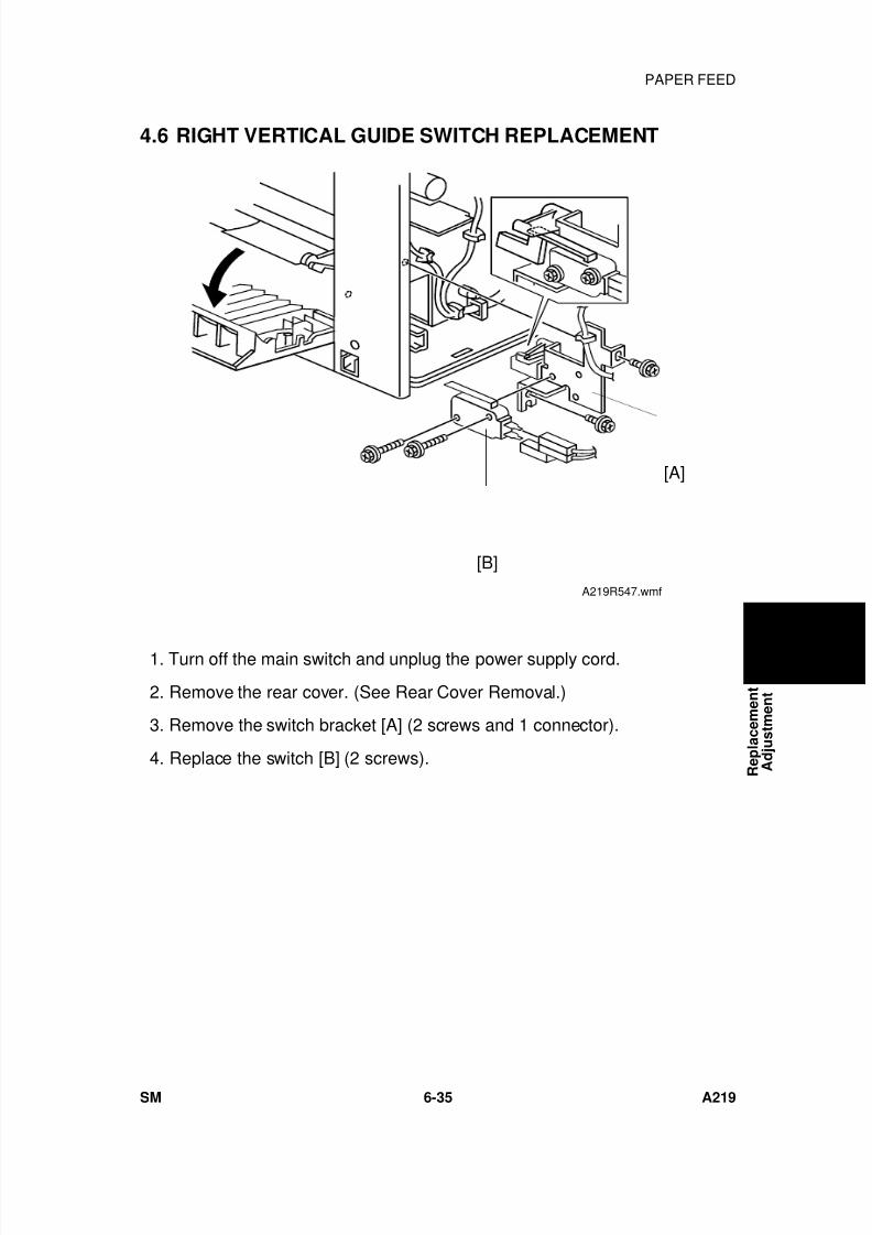
7/18/2019 A219 245 B019 4015 3813 Service
http://slidepdf.com/reader/full/a219-245-b019-4015-3813-service 196/372
4.6 RIGHT VERTICAL GUIDE SWITCH REPLACEMENT
1. Turn off the main switch and unplug the power supply cord.
2. Remove the rear cover. (See Rear Cover Removal.)
3. Remove the switch bracket [A] (2 screws and 1 connector).
4. Replace the switch [B] (2 screws).
[B]
[A]
A219R547.wmf
R e p l a c e m e n t
A d j u s t m e n t
PAPER FEED
SM 6-35 A219
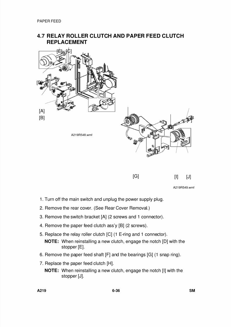
7/18/2019 A219 245 B019 4015 3813 Service
http://slidepdf.com/reader/full/a219-245-b019-4015-3813-service 197/372
4.7 RELAY ROLLER CLUTCH AND PAPER FEED CLUTCHREPLACEMENT
1. Turn off the main switch and unplug the power supply plug.
2. Remove the rear cover. (See Rear Cover Removal.)
3. Remove the switch bracket [A] (2 screws and 1 connector).
4. Remove the paper feed clutch ass’y [B] (2 screws). 5. Replace the relay roller clutch [C] (1 E-ring and 1 connector).
NOTE: When reinstalling a new clutch, engage the notch [D] with thestopper [E].
6. Remove the paper feed shaft [F] and the bearings [G] (1 snap ring).
7. Replace the paper feed clutch [H].
NOTE: When reinstalling a new clutch, engage the notch [I] with thestopper [J].
[E] [C]
[D]
[A]
[B]
A219R548.wmf
[H] [F]
[J][I][G]
[G]
A219R549.wmf
PAPER FEED
A219 6-36 SM
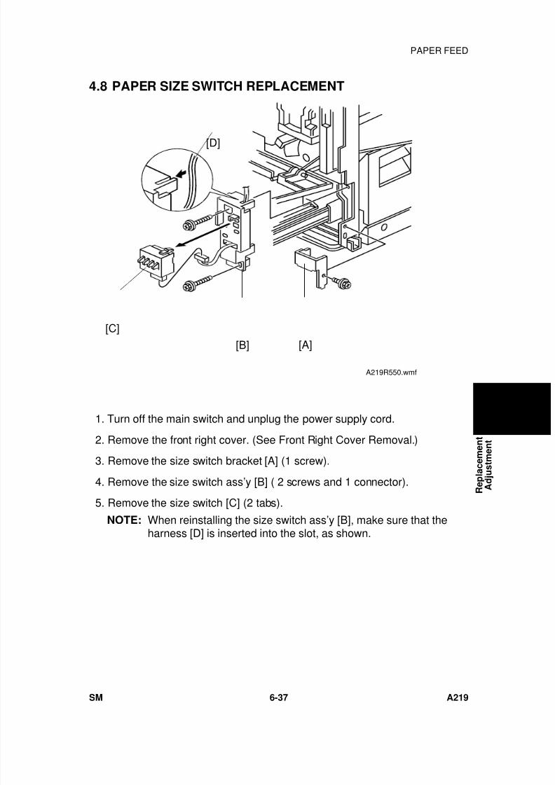
7/18/2019 A219 245 B019 4015 3813 Service
http://slidepdf.com/reader/full/a219-245-b019-4015-3813-service 198/372
4.8 PAPER SIZE SWITCH REPLACEMENT
1. Turn off the main switch and unplug the power supply cord.
2. Remove the front right cover. (See Front Right Cover Removal.)
3. Remove the size switch bracket [A] (1 screw).
4. Remove the size switch ass’y [B] ( 2 screws and 1 connector).
5. Remove the size switch [C] (2 tabs).
NOTE: When reinstalling the size switch ass’y [B], make sure that theharness [D] is inserted into the slot, as shown.
[D]
[C]
[B] [A]
A219R550.wmf
R e p l a c e m e n t
A d j u s t m e n t
PAPER FEED
SM 6-37 A219
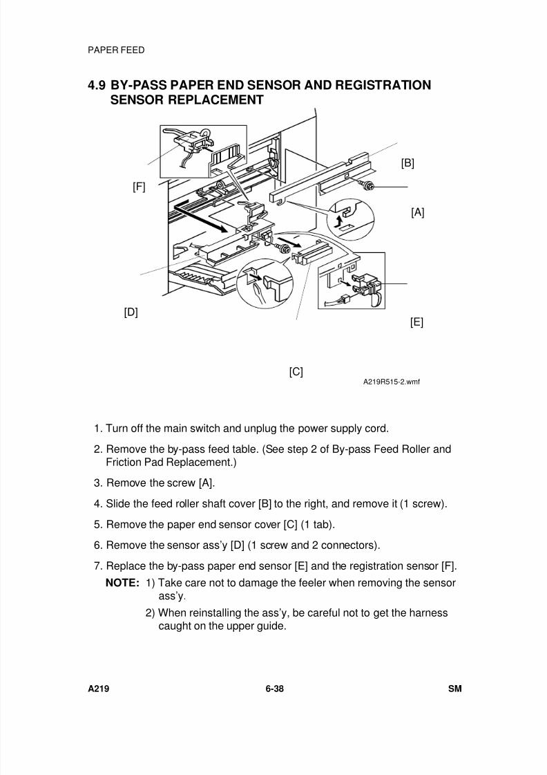
7/18/2019 A219 245 B019 4015 3813 Service
http://slidepdf.com/reader/full/a219-245-b019-4015-3813-service 199/372
4.9 BY-PASS PAPER END SENSOR AND REGISTRATIONSENSOR REPLACEMENT
1. Turn off the main switch and unplug the power supply cord.
2. Remove the by-pass feed table. (See step 2 of By-pass Feed Roller andFriction Pad Replacement.)
3. Remove the screw [A].
4. Slide the feed roller shaft cover [B] to the right, and remove it (1 screw).
5. Remove the paper end sensor cover [C] (1 tab).
6. Remove the sensor ass’y [D] (1 screw and 2 connectors).
7. Replace the by-pass paper end sensor [E] and the registration sensor [F].
NOTE: 1) Take care not to damage the feeler when removing the sensorass’y.
2) When reinstalling the ass’y, be careful not to get the harnesscaught on the upper guide.
[F]
[B]
[A]
[E]
[C]
[D]
A219R515-2.wmf
PAPER FEED
A219 6-38 SM
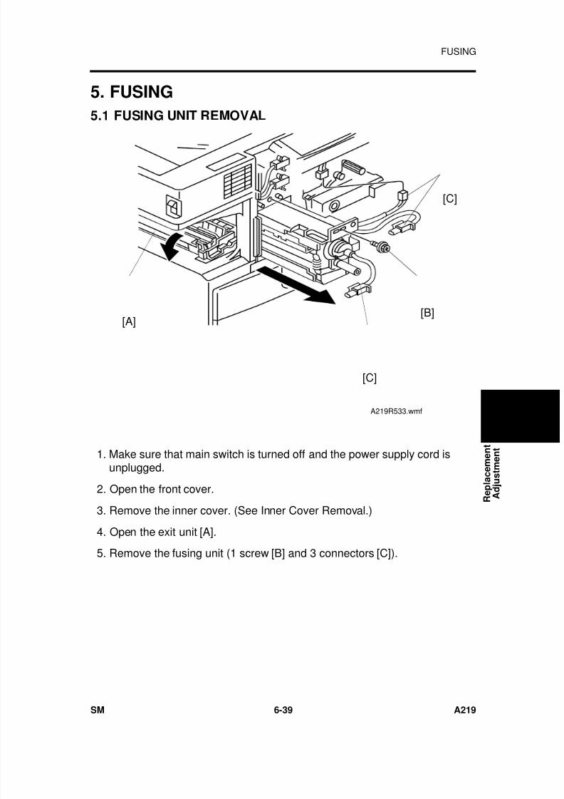
7/18/2019 A219 245 B019 4015 3813 Service
http://slidepdf.com/reader/full/a219-245-b019-4015-3813-service 200/372
5. FUSING
5.1 FUSING UNIT REMOVAL
1. Make sure that main switch is turned off and the power supply cord isunplugged.
2. Open the front cover.
3. Remove the inner cover. (See Inner Cover Removal.)
4. Open the exit unit [A].
5. Remove the fusing unit (1 screw [B] and 3 connectors [C]).
[A][B]
[C]
[C]
A219R533.wmf
R e p l a c e m e n t
A d j u s t m e n t
FUSING
SM 6-39 A219
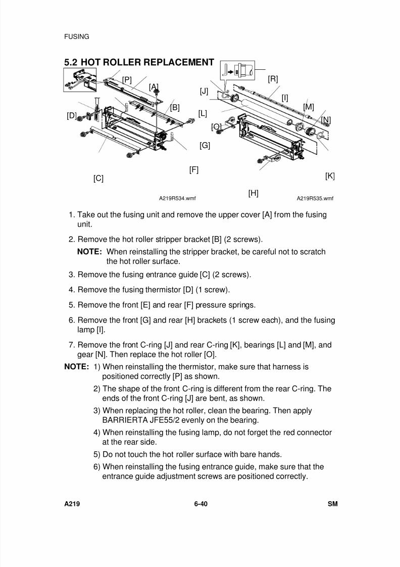
7/18/2019 A219 245 B019 4015 3813 Service
http://slidepdf.com/reader/full/a219-245-b019-4015-3813-service 201/372
5.2 HOT ROLLER REPLACEMENT
1. Take out the fusing unit and remove the upper cover [A] from the fusingunit.
2. Remove the hot roller stripper bracket [B] (2 screws).
NOTE: When reinstalling the stripper bracket, be careful not to scratchthe hot roller surface.
3. Remove the fusing entrance guide [C] (2 screws).
4. Remove the fusing thermistor [D] (1 screw).
5. Remove the front [E] and rear [F] pressure springs.
6. Remove the front [G] and rear [H] brackets (1 screw each), and the fusinglamp [I].
7. Remove the front C-ring [J] and rear C-ring [K], bearings [L] and [M], andgear [N]. Then replace the hot roller [O].
NOTE: 1) When reinstalling the thermistor, make sure that harness ispositioned correctly [P] as shown.
2) The shape of the front C-ring is different from the rear C-ring. Theends of the front C-ring [J] are bent, as shown.
3) When replacing the hot roller, clean the bearing. Then applyBARRIERTA JFE55/2 evenly on the bearing.
4) When reinstalling the fusing lamp, do not forget the red connectorat the rear side.
5) Do not touch the hot roller surface with bare hands.
6) When reinstalling the fusing entrance guide, make sure that theentrance guide adjustment screws are positioned correctly.
[P][A]
[B][D]
[C]
[E]
[F]
A219R534.wmf
[R]
[G]
[H]
[N]
[K]
[L]
[J]
[M][I]
[O]
A219R535.wmf
FUSING
A219 6-40 SM
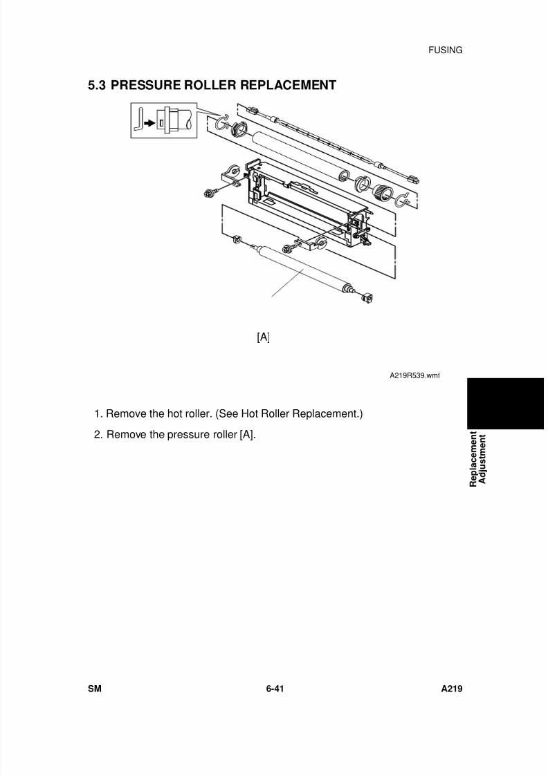
7/18/2019 A219 245 B019 4015 3813 Service
http://slidepdf.com/reader/full/a219-245-b019-4015-3813-service 202/372
5.3 PRESSURE ROLLER REPLACEMENT
1. Remove the hot roller. (See Hot Roller Replacement.)
2. Remove the pressure roller [A].
[A]
A219R539.wmf
R e p l a c e m e n t
A d j u s t m e n t
FUSING
SM 6-41 A219
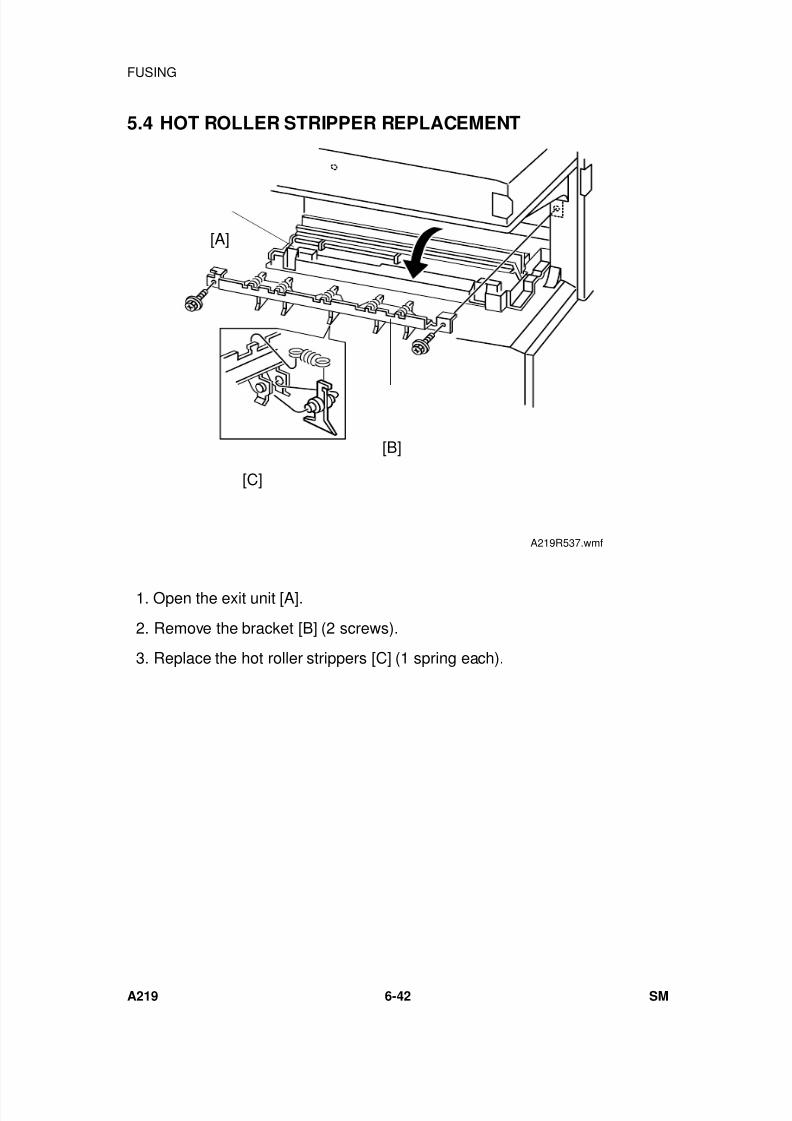
7/18/2019 A219 245 B019 4015 3813 Service
http://slidepdf.com/reader/full/a219-245-b019-4015-3813-service 203/372
5.4 HOT ROLLER STRIPPER REPLACEMENT
1. Open the exit unit [A].
2. Remove the bracket [B] (2 screws).
3. Replace the hot roller strippers [C] (1 spring each).
[A]
[B]
[C]
A219R537.wmf
FUSING
A219 6-42 SM
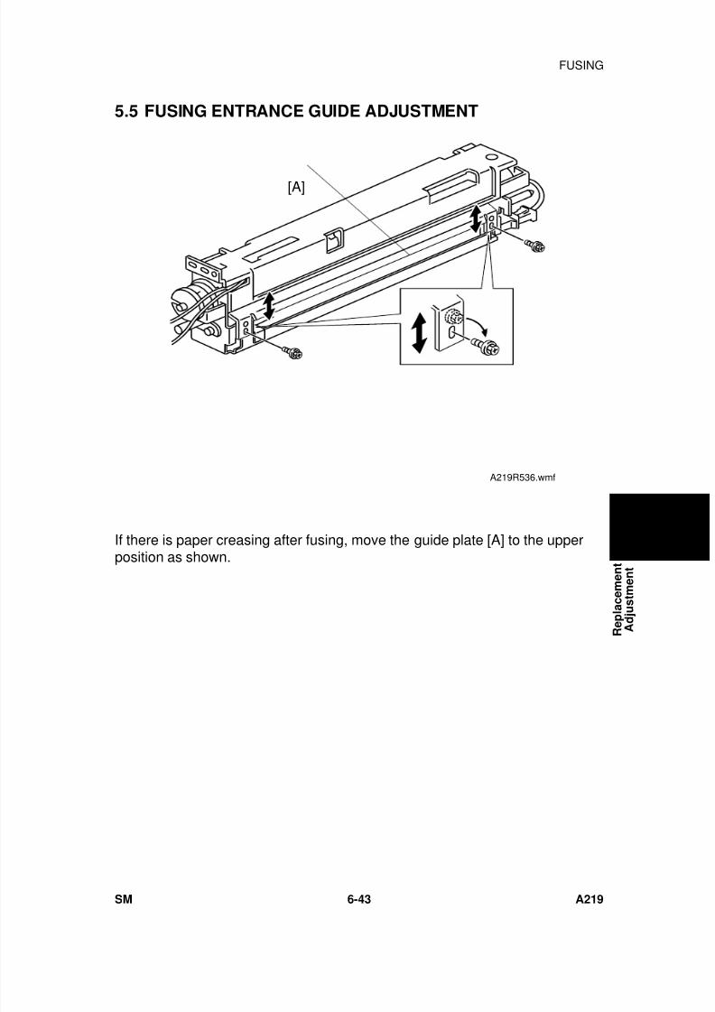
7/18/2019 A219 245 B019 4015 3813 Service
http://slidepdf.com/reader/full/a219-245-b019-4015-3813-service 204/372
5.5 FUSING ENTRANCE GUIDE ADJUSTMENT
If there is paper creasing after fusing, move the guide plate [A] to the upperposition as shown.
[A]
A219R536.wmf
R e p l a c e m e n t
A d j u s t m e n t
FUSING
SM 6-43 A219
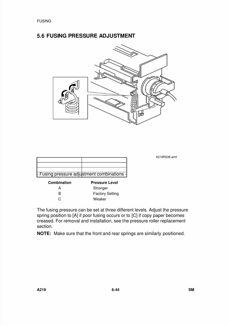
7/18/2019 A219 245 B019 4015 3813 Service
http://slidepdf.com/reader/full/a219-245-b019-4015-3813-service 205/372
5.6 FUSING PRESSURE ADJUSTMENT
- Fusing pressure adjustment combinations -
Combination Pressure Level
A StrongerB Factory SettingC Weaker
The fusing pressure can be set at three different levels. Adjust the pressurespring position to [A] if poor fusing occurs or to [C] if copy paper becomescreased. For removal and installation, see the pressure roller replacement
section.NOTE: Make sure that the front and rear springs are similarly positioned.
A
CB
A219R538.wmf
FUSING
A219 6-44 SM
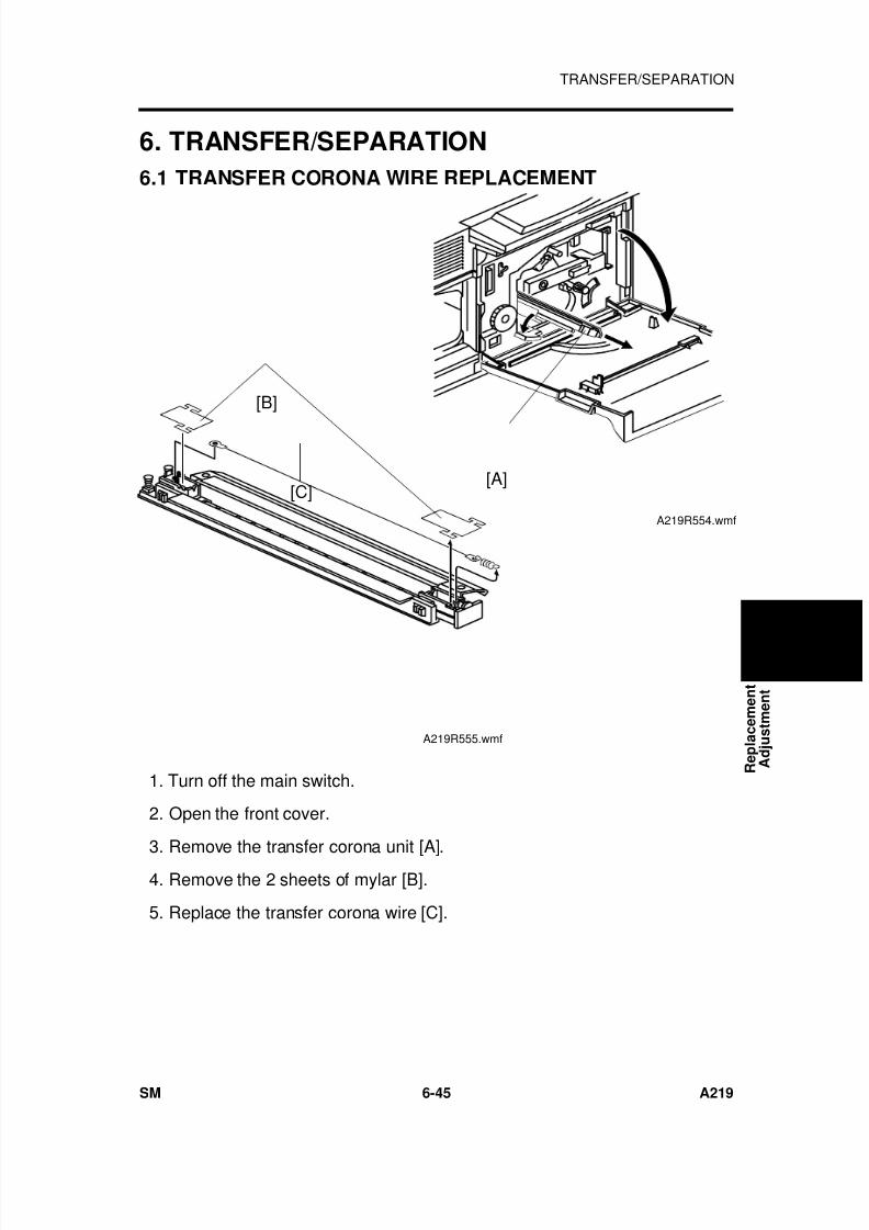
7/18/2019 A219 245 B019 4015 3813 Service
http://slidepdf.com/reader/full/a219-245-b019-4015-3813-service 206/372
6. TRANSFER/SEPARATION
6.1 TRANSFER CORONA WIRE REPLACEMENT
1. Turn off the main switch.
2. Open the front cover.
3. Remove the transfer corona unit [A]. 4. Remove the 2 sheets of mylar [B].
5. Replace the transfer corona wire [C].
[A]
A219R554.wmf
[C]
[B]
A219R555.wmf
R e p l a c e m e n t
A d j u s t m e n t
TRANSFER/SEPARATION
SM 6-45 A219
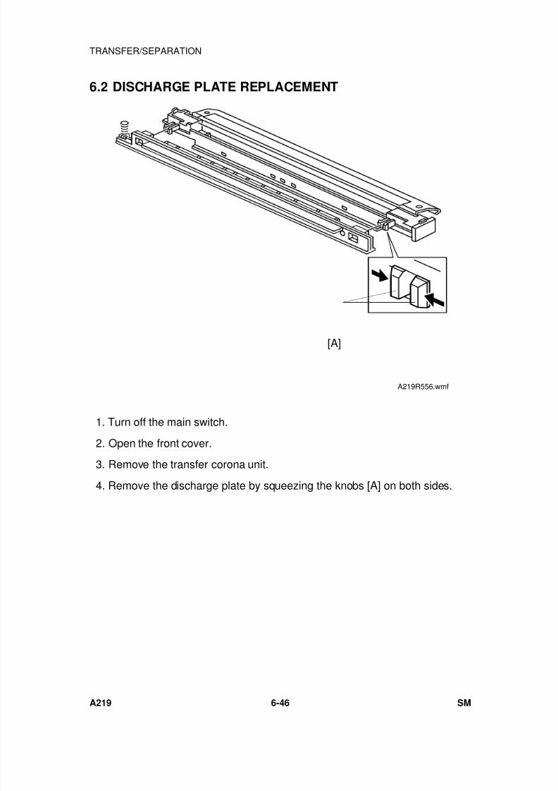
7/18/2019 A219 245 B019 4015 3813 Service
http://slidepdf.com/reader/full/a219-245-b019-4015-3813-service 207/372
6.2 DISCHARGE PLATE REPLACEMENT
1. Turn off the main switch.
2. Open the front cover.
3. Remove the transfer corona unit.
4. Remove the discharge plate by squeezing the knobs [A] on both sides.
[A]
A219R556.wmf
TRANSFER/SEPARATION
A219 6-46 SM
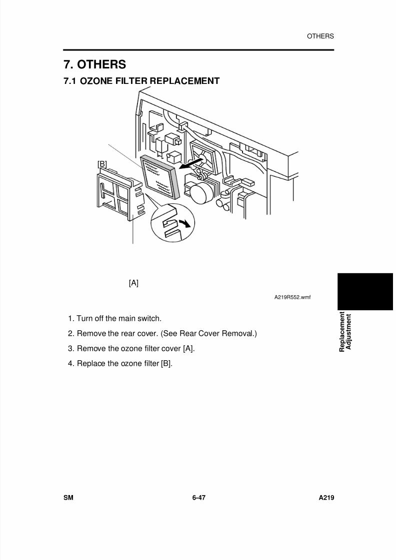
7/18/2019 A219 245 B019 4015 3813 Service
http://slidepdf.com/reader/full/a219-245-b019-4015-3813-service 208/372
7. OTHERS
7.1 OZONE FILTER REPLACEMENT
1. Turn off the main switch.
2. Remove the rear cover. (See Rear Cover Removal.)
3. Remove the ozone filter cover [A].
4. Replace the ozone filter [B].
[B]
[A]
A219R552.wmf
R e p l a c e m e n t
A d j u s t m e n t
OTHERS
SM 6-47 A219
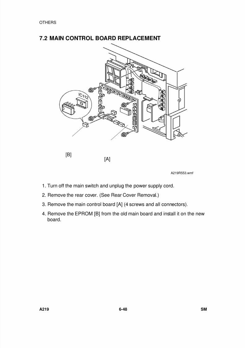
7/18/2019 A219 245 B019 4015 3813 Service
http://slidepdf.com/reader/full/a219-245-b019-4015-3813-service 209/372
7.2 MAIN CONTROL BOARD REPLACEMENT
1. Turn off the main switch and unplug the power supply cord.
2. Remove the rear cover. (See Rear Cover Removal.)
3. Remove the main control board [A] (4 screws and all connectors).
4. Remove the EPROM [B] from the old main board and install it on the newboard.
[B][A]
A219R553.wmf
OTHERS
A219 6-48 SM

7/18/2019 A219 245 B019 4015 3813 Service
http://slidepdf.com/reader/full/a219-245-b019-4015-3813-service 210/372
8. COPY QUALITY ADJUSTMENT
- General Information -
Image density is affected by the following factors:
(1) Light Intensity(2) Development Bias Voltage(3) Toner Density(4) Grid Voltage/Drum Current
The items listed above must be kept in balance to maintain correct imagedensity.
In the field, image density should be adjusted first by changing theexposure lamp voltage. If results are unsatisfactory, the bias voltage
can be changed (SP33/34). Also, if requested by the customer, theoverall image density can be changed by changing the toner density(SP38/UP6). Normally, this should be kept at the normal position(factory setting).
The grid voltage and charge corona current are carefully adjusted at thefactory. Any adjustment out of the adjustment standard will result inovertoning, toner scattering, dirty background, or light image densityproblems. The grid voltage and charge corona current adjustmentshould be done only when replacing the power pack or to correct
certain problems with image density after checking all other possible
causes.
R e p l a c e m e n t
A d j u s t m e n t
COPY QUALITY ADJUSTMENT
SM 6-49 A219
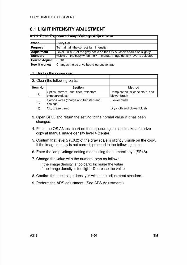
7/18/2019 A219 245 B019 4015 3813 Service
http://slidepdf.com/reader/full/a219-245-b019-4015-3813-service 211/372
8.1 LIGHT INTENSITY ADJUSTMENT
8.1.1 Base Exposure Lamp Voltage Adjustment
When: Every CallPurpose: To maintain the correct light intensity.AdjustmentStandard:
Level 2 (E0.2) of the gray scale on the OS-A3 chart should be slightlyvisible on the copy when the 4th manual image density level is selected.
How to Adjust: SP48How it works: Changes the ac drive board output voltage.
1. Unplug the power cord.
2. Clean the following parts:
Item No. Section Method
(1) Optics (mirrors, lens, filter, reflectors,exposure glass) Damp cotton, silicone cloth, andblower brush
(2)Corona wires (charge and transfer) andcasings.
Blower blush
(3) QL, Erase Lamp Dry cloth and blower blush
3. Open SP33 and return the setting to the normal value if it has beenchanged.
4. Place the OS-A3 test chart on the exposure glass and make a full sizecopy at manual image density level 4 (center).
5. Confirm that level 2 (E0.2) of the gray scale is slightly visible on the copy.If the image density is not correct, proceed to the following steps.
6. Enter the lamp voltage setting mode using the numeral keys (SP48).
7. Change the value with the numeral keys as follows:If the image density is too dark: Increase the valueIf the image density is too light: Decrease the value
8. Confirm that the image density is within the adjustment standard.
9. Perform the ADS adjustment. (See ADS Adjustment.)
COPY QUALITY ADJUSTMENT
A219 6-50 SM
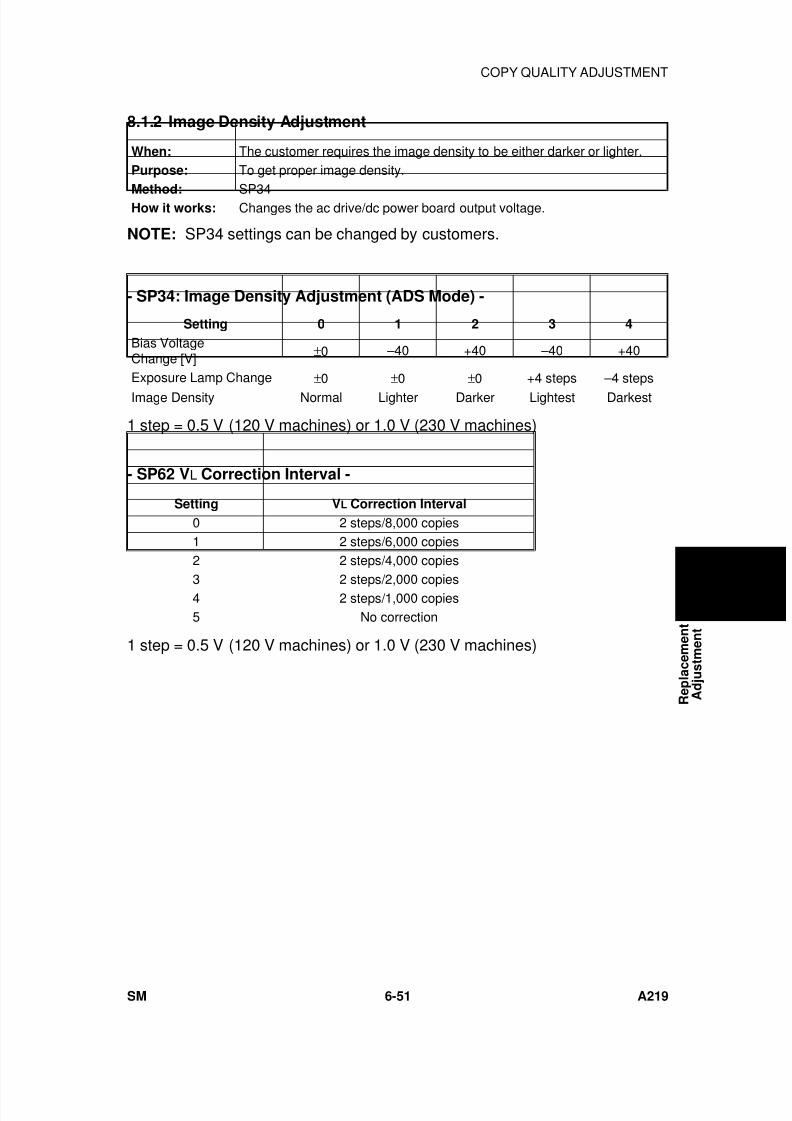
7/18/2019 A219 245 B019 4015 3813 Service
http://slidepdf.com/reader/full/a219-245-b019-4015-3813-service 212/372
8.1.2 Image Density Adjustment
When: The customer requires the image density to be either darker or lighter.Purpose: To get proper image density.
Method: SP34How it works: Changes the ac drive/dc power board output voltage.
NOTE: SP34 settings can be changed by customers.
- SP34: Image Density Adjustment (ADS Mode) -
Setting 0 1 2 3 4
Bias VoltageChange [V] ±0 –40 +40 –40 +40
Exposure Lamp Change ±0 ±0 ±0 +4 steps –4 steps
Image Density Normal Lighter Darker Lightest Darkest
1 step = 0.5 V (120 V machines) or 1.0 V (230 V machines)
- SP62 VL Correction Interval -
Setting VL Correction Interval
0 2 steps/8,000 copies1 2 steps/6,000 copies2 2 steps/4,000 copies
3 2 steps/2,000 copies4 2 steps/1,000 copies5 No correction
1 step = 0.5 V (120 V machines) or 1.0 V (230 V machines)
R e p l a c e m e n t
A d j u s t m e n t
COPY QUALITY ADJUSTMENT
SM 6-51 A219
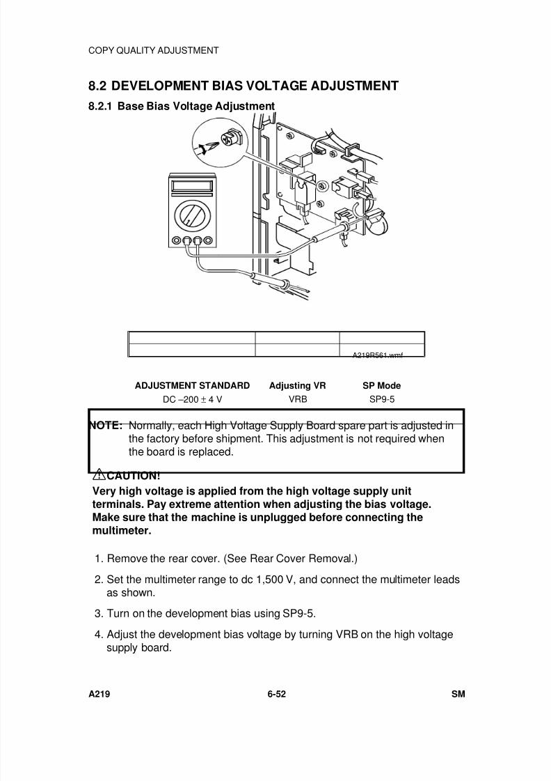
7/18/2019 A219 245 B019 4015 3813 Service
http://slidepdf.com/reader/full/a219-245-b019-4015-3813-service 213/372
8.2 DEVELOPMENT BIAS VOLTAGE ADJUSTMENT
8.2.1 Base Bias Voltage Adjustment
ADJUSTMENT STANDARD Adjusting VR SP Mode
DC –200 ± 4 V VRB SP9-5
NOTE: Normally, each High Voltage Supply Board spare part is adjusted inthe factory before shipment. This adjustment is not required whenthe board is replaced.
CAUTION!
Very high voltage is applied from the high voltage supply unitterminals. Pay extreme attention when adjusting the bias voltage.Make sure that the machine is unplugged before connecting themultimeter.
1. Remove the rear cover. (See Rear Cover Removal.)
2. Set the multimeter range to dc 1,500 V, and connect the multimeter leadsas shown.
3. Turn on the development bias using SP9-5.
4. Adjust the development bias voltage by turning VRB on the high voltagesupply board.
A219R561.wmf
COPY QUALITY ADJUSTMENT
A219 6-52 SM
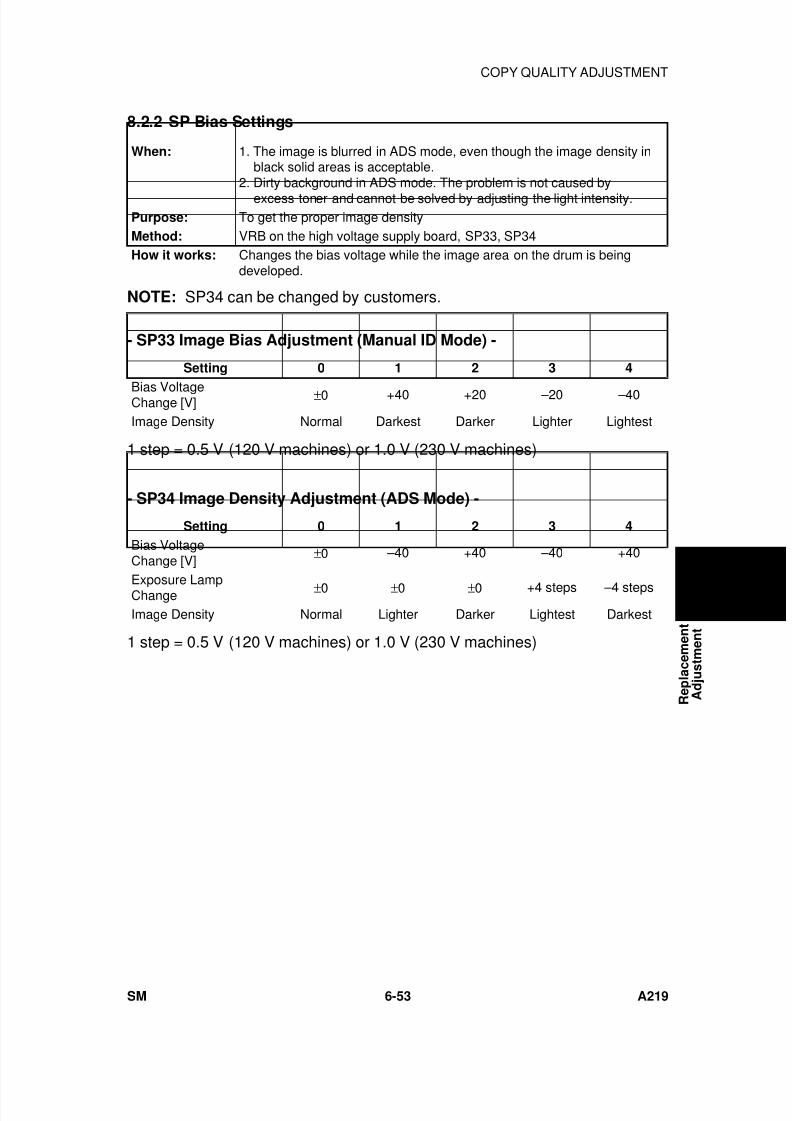
7/18/2019 A219 245 B019 4015 3813 Service
http://slidepdf.com/reader/full/a219-245-b019-4015-3813-service 214/372
8.2.2 SP Bias Settings
When: 1. The image is blurred in ADS mode, even though the image density in black solid areas is acceptable.2. Dirty background in ADS mode. The problem is not caused by
excess toner and cannot be solved by adjusting the light intensity.Purpose: To get the proper image densityMethod: VRB on the high voltage supply board, SP33, SP34How it works: Changes the bias voltage while the image area on the drum is being
developed.
NOTE: SP34 can be changed by customers.
- SP33 Image Bias Adjustment (Manual ID Mode) -
Setting 0 1 2 3 4
Bias VoltageChange [V] ±0 +40 +20 –20 –40
Image Density Normal Darkest Darker Lighter Lightest
1 step = 0.5 V (120 V machines) or 1.0 V (230 V machines)
- SP34 Image Density Adjustment (ADS Mode) -
Setting 0 1 2 3 4
Bias VoltageChange [V] ±0 –40 +40 –40 +40
Exposure LampChange ±0 ±0 ±0 +4 steps –4 steps
Image Density Normal Lighter Darker Lightest Darkest
1 step = 0.5 V (120 V machines) or 1.0 V (230 V machines)
R e p l a c e m e n t
A d j u s t m e n t
COPY QUALITY ADJUSTMENT
SM 6-53 A219
7/18/2019 A219 245 B019 4015 3813 Service
http://slidepdf.com/reader/full/a219-245-b019-4015-3813-service 215/372
8.3 TONER DENSITY ADJUSTMENT
When: The customer wants to change the overall image density of the copies.Purpose: To change the toner concentration inside the development unit.
How to Adjust: SP38How it works: Changes the development bias voltage and either raises/lowers the toner
supply threshold.
NOTE: SP38 can be changed by customers.
8.4 TONER SUPPLY RATIO SELECTION
When: The factory setting for the toner supply amount is not appropriate for thetype of original in use.
Purpose: To adjust the toner supply amount.AdjustmentStandard:
TD Sensor Mode: 0.4 s (Factory Setting)Fixed Mode: 0.3 s (Factory Setting)
How to Adjust: Detect Mode (using TD sensor): SP31Fixed Mode: SP32
How it works: Changes the interval that the toner supply motor is on.
COPY QUALITY ADJUSTMENT
A219 6-54 SM
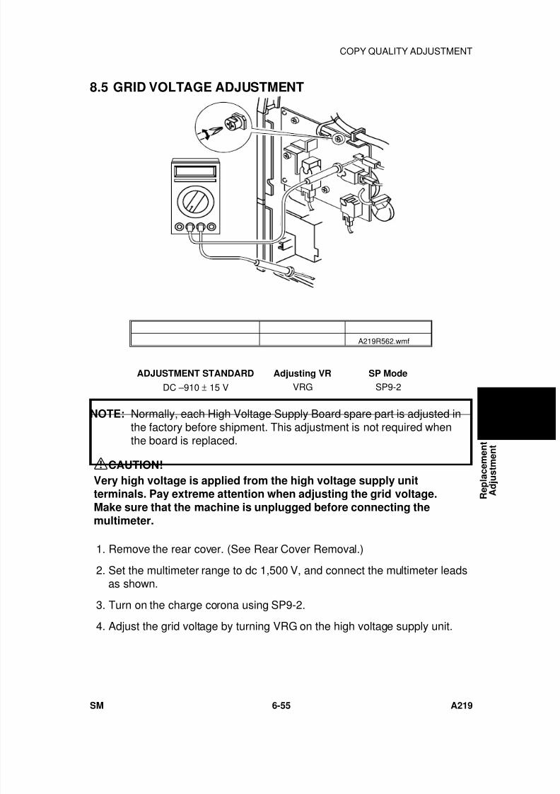
7/18/2019 A219 245 B019 4015 3813 Service
http://slidepdf.com/reader/full/a219-245-b019-4015-3813-service 216/372
8.5 GRID VOLTAGE ADJUSTMENT
ADJUSTMENT STANDARD Adjusting VR SP Mode
DC –910 ± 15 V VRG SP9-2
NOTE: Normally, each High Voltage Supply Board spare part is adjusted inthe factory before shipment. This adjustment is not required whenthe board is replaced.
CAUTION!
Very high voltage is applied from the high voltage supply unitterminals. Pay extreme attention when adjusting the grid voltage.Make sure that the machine is unplugged before connecting themultimeter.
1. Remove the rear cover. (See Rear Cover Removal.) 2. Set the multimeter range to dc 1,500 V, and connect the multimeter leads
as shown.
3. Turn on the charge corona using SP9-2.
4. Adjust the grid voltage by turning VRG on the high voltage supply unit.
A219R562.wmf
R e p l a c e m e n t
A d j u s t m e n t
COPY QUALITY ADJUSTMENT
SM 6-55 A219
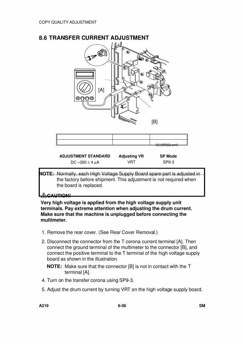
7/18/2019 A219 245 B019 4015 3813 Service
http://slidepdf.com/reader/full/a219-245-b019-4015-3813-service 217/372
8.6 TRANSFER CURRENT ADJUSTMENT
ADJUSTMENT STANDARD Adjusting VR SP Mode
DC –350 ± 4 µA VRT SP9-3
NOTE: Normally, each High Voltage Supply Board spare part is adjusted in
the factory before shipment. This adjustment is not required whenthe board is replaced.
CAUTION!
Very high voltage is applied from the high voltage supply unit
terminals. Pay extreme attention when adjusting the drum current.Make sure that the machine is unplugged before connecting themultimeter.
1. Remove the rear cover. (See Rear Cover Removal.)
2. Disconnect the connector from the T corona current terminal [A]. Thenconnect the ground terminal of the multimeter to the connector [B], andconnect the positive terminal to the T terminal of the high voltage supplyboard as shown in the illustration.
NOTE: Make sure that the connector [B] is not in contact with the Tterminal [A].
4. Turn on the transfer corona using SP9-3.
5. Adjust the drum current by turning VRT on the high voltage supply board.
[A]
[B]
A219R563.wmf
COPY QUALITY ADJUSTMENT
A219 6-56 SM
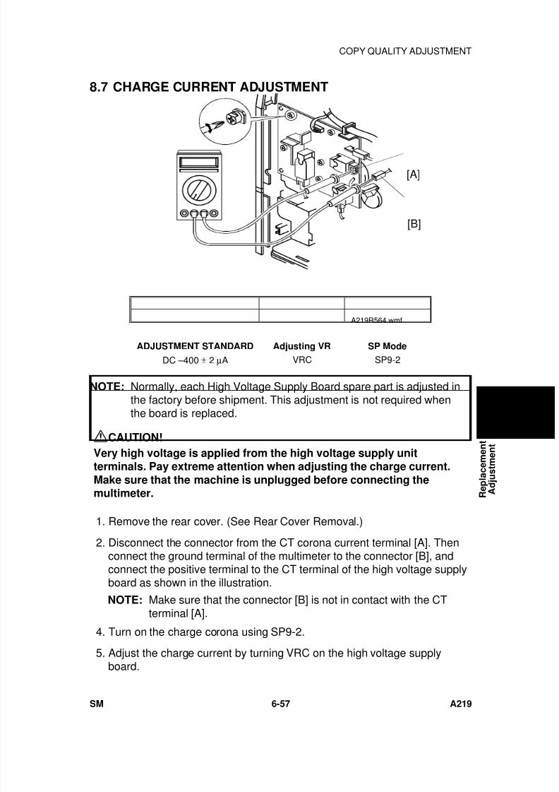
7/18/2019 A219 245 B019 4015 3813 Service
http://slidepdf.com/reader/full/a219-245-b019-4015-3813-service 218/372
8.7 CHARGE CURRENT ADJUSTMENT
ADJUSTMENT STANDARD Adjusting VR SP Mode
DC –400 ± 2 µA VRC SP9-2
NOTE: Normally, each High Voltage Supply Board spare part is adjusted inthe factory before shipment. This adjustment is not required when
the board is replaced.
CAUTION!
Very high voltage is applied from the high voltage supply unitterminals. Pay extreme attention when adjusting the charge current.
Make sure that the machine is unplugged before connecting themultimeter.
1. Remove the rear cover. (See Rear Cover Removal.)
2. Disconnect the connector from the CT corona current terminal [A]. Thenconnect the ground terminal of the multimeter to the connector [B], andconnect the positive terminal to the CT terminal of the high voltage supplyboard as shown in the illustration.
NOTE: Make sure that the connector [B] is not in contact with the CTterminal [A].
4. Turn on the charge corona using SP9-2.
5. Adjust the charge current by turning VRC on the high voltage supplyboard.
[A]
[B]
A219R564.wmf
R e p l a c e m e n t
A d j u s t m e n t
COPY QUALITY ADJUSTMENT
SM 6-57 A219
7/18/2019 A219 245 B019 4015 3813 Service
http://slidepdf.com/reader/full/a219-245-b019-4015-3813-service 219/372
8.8 HORIZONTAL MAGNIFICATION ADJUSTMENT
When: The horizontal magnification is not within the adjustment standard.Purpose: To maintain proper horizontal magnification.
AdjustmentStandard:
Less than ± 0.8% difference between original and copy.
How to Adjust: SP44 (0.2%/step, 51 steps)How it works: Changes the lens home position.
1. Change the value of SP44 to 20 (default value).
2. Confirm that the scanner wire clamps are positioned correctly using thescanner positioning pins. (See 1st and 2nd Scanner Adjustment.)
3. Place a 150 mm scale parallel to the left scale on the exposure glass.
4. Adjust the horizontal magnification using SP44. Make three copies tocheck the magnification.
NOTE: If the copy image is out of focus as making copies after thisadjustment, adjust the focus. (See Focus Adjustment.)
8.9 VERTICAL MAGNIFICATION ADJUSTMENT
When: The vertical magnification is not within the adjustment standard.
Purpose: To maintain proper vertical magnification.AdjustmentStandard:
Less than ± 1.0% difference between original and copy.
How to Adjust: SP43 (0.2%/step, 32 steps)How it works: Changes the scanner speed.
1. Place a 150 mm scale perpendicular to the left scale on the exposureglass.
2. Adjust the vertical magnification using SP43. Make three copies to checkthe magnification.
NOTE: If the copy image is out of focus as making copies after thisadjustment, adjust the focus. (See Focus Adjustment.)
COPY QUALITY ADJUSTMENT
A219 6-58 SM
7/18/2019 A219 245 B019 4015 3813 Service
http://slidepdf.com/reader/full/a219-245-b019-4015-3813-service 220/372
8.10 FOCUS ADJUSTMENT
When: The copy image is out of focus.After adjusting the horizontal magnification.
Purpose: To maintain proper focus.AdjustmentStandard:
Copy image in focus.
How to Adjust: SP47 (0.1 mm/step,101 steps)How it works: Adjusts the 4th/5th mirror assembly home position, changing the
distance between the original and the drum surface.
1. Make three copies with the test chart.
2. Adjust the focus using SP47. Check the text on the copies.
8.11 LEADING EDGE ERASE MARGIN ADJUSTMENT
When: The leading edge erase margin is not within the adjustment standard.Purpose: To maintain the correct leading erase margin.AdjustmentStandard:
2.5 ± 2.0 mm (0.1 ± 0.08")
How to Adjust: SP41 (0.5 mm/step, 16 steps)How it works: Changes the erase lamp on period.
1. Place a 150 mm scale perpendicular to the left scale on the exposureglass.
2. Adjust the leading edge erase margin using SP41. Make three copiesand check the erase margin.
8.12 REGISTRATION ADJUSTMENT
When: Registration is not within the adjustment standard.Purpose: To maintain proper registration.
AdjustmentStandard:
0 ± 2 mm (0 ± 0.08")
How to Adjust: SP42 (0.5 mm/step, 16 steps)How it works: Changes the registration roller start timing.
1. Place a 150 mm scale perpendicular to the left scale on the exposureglass.
2. Adjust the registration using SP42. Make three copies and check theregistration.
R e p l a c e m e n t
A d j u s t m e n t
COPY QUALITY ADJUSTMENT
SM 6-59 A219
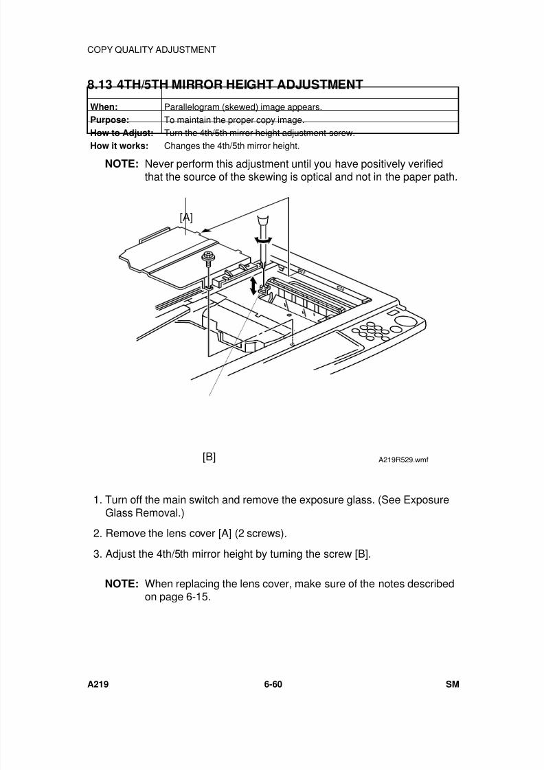
7/18/2019 A219 245 B019 4015 3813 Service
http://slidepdf.com/reader/full/a219-245-b019-4015-3813-service 221/372
8.13 4TH/5TH MIRROR HEIGHT ADJUSTMENT
When: Parallelogram (skewed) image appears.Purpose: To maintain the proper copy image.
How to Adjust: Turn the 4th/5th mirror height adjustment screw.How it works: Changes the 4th/5th mirror height.
NOTE: Never perform this adjustment until you have positively verifiedthat the source of the skewing is optical and not in the paper path.
1. Turn off the main switch and remove the exposure glass. (See ExposureGlass Removal.)
2. Remove the lens cover [A] (2 screws). 3. Adjust the 4th/5th mirror height by turning the screw [B].
NOTE: When replacing the lens cover, make sure of the notes describedon page 6-15.
[A]
[B] A219R529.wmf
COPY QUALITY ADJUSTMENT
A219 6-60 SM
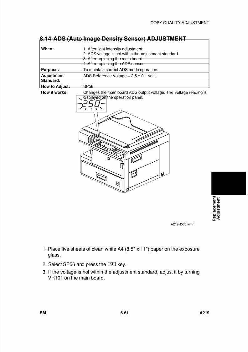
7/18/2019 A219 245 B019 4015 3813 Service
http://slidepdf.com/reader/full/a219-245-b019-4015-3813-service 222/372
8.14 ADS (Auto Image Density Sensor) ADJUSTMENT
When: 1. After light intensity adjustment.2. ADS voltage is not within the adjustment standard.3. After replacing the main board.4. After replacing the ADS sensor.
Purpose: To maintain correct ADS mode operation.AdjustmentStandard:
ADS Reference Voltage = 2.5 ± 0.1 volts
How to Adjust: SP56How it works: Changes the main board ADS output voltage. The voltage reading is
displayed on the operation panel.
1. Place five sheets of clean white A4 (8.5" x 11") paper on the exposureglass.
2. Select SP56 and press the key.
3. If the voltage is not within the adjustment standard, adjust it by turningVR101 on the main board.
A219R530.wmf R e p l a c e m e n t
A d j u s t m e n t
COPY QUALITY ADJUSTMENT
SM 6-61 A219
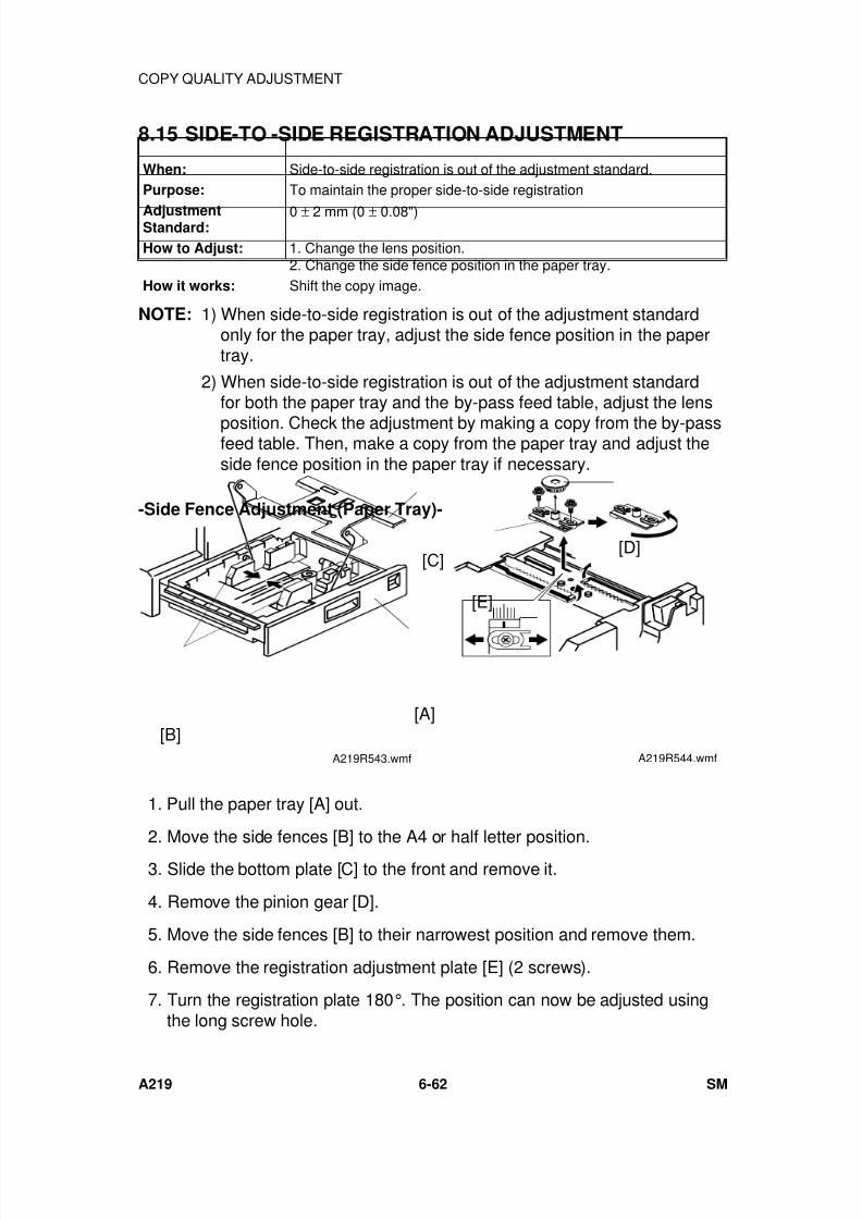
7/18/2019 A219 245 B019 4015 3813 Service
http://slidepdf.com/reader/full/a219-245-b019-4015-3813-service 223/372
8.15 SIDE-TO -SIDE REGISTRATION ADJUSTMENT
When: Side-to-side registration is out of the adjustment standard.Purpose: To maintain the proper side-to-side registration
AdjustmentStandard:
0 ± 2 mm (0 ± 0.08")
How to Adjust: 1. Change the lens position.2. Change the side fence position in the paper tray.
How it works: Shift the copy image.
NOTE: 1) When side-to-side registration is out of the adjustment standardonly for the paper tray, adjust the side fence position in the papertray.
2) When side-to-side registration is out of the adjustment standardfor both the paper tray and the by-pass feed table, adjust the lens
position. Check the adjustment by making a copy from the by-passfeed table. Then, make a copy from the paper tray and adjust theside fence position in the paper tray if necessary.
-Side Fence Adjustment (Paper Tray)-
1. Pull the paper tray [A] out.
2. Move the side fences [B] to the A4 or half letter position.
3. Slide the bottom plate [C] to the front and remove it.
4. Remove the pinion gear [D].
5. Move the side fences [B] to their narrowest position and remove them.
6. Remove the registration adjustment plate [E] (2 screws).
7. Turn the registration plate 180°. The position can now be adjusted usingthe long screw hole.
[C]
[A][B]
A219R543.wmf
[D]
[E]
A219R544.wmf
COPY QUALITY ADJUSTMENT
A219 6-62 SM
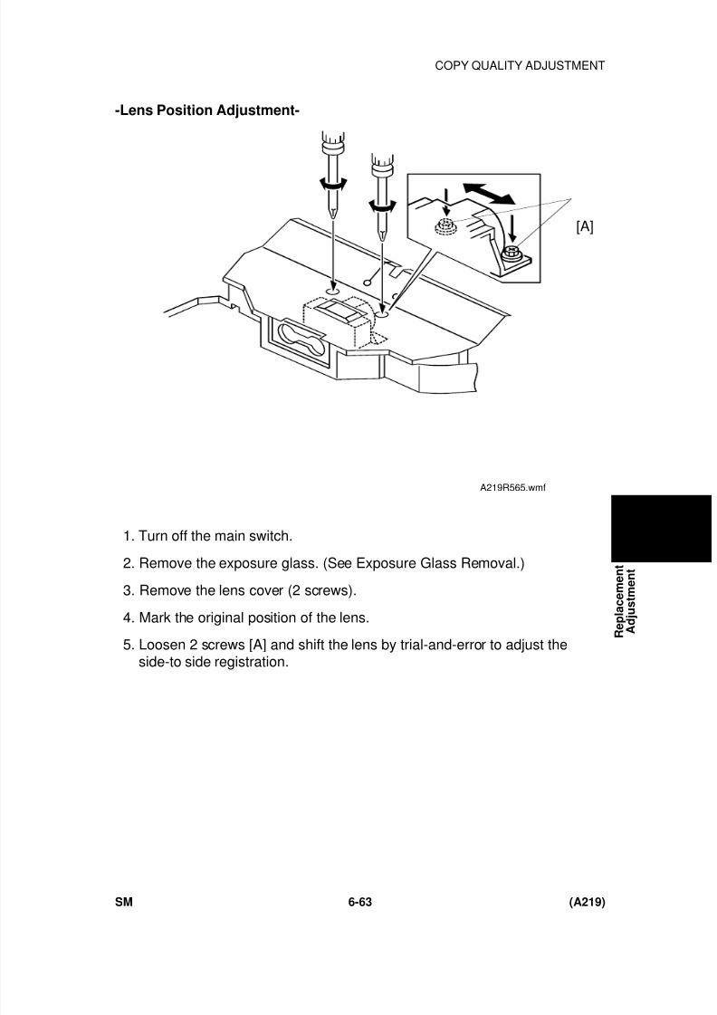
7/18/2019 A219 245 B019 4015 3813 Service
http://slidepdf.com/reader/full/a219-245-b019-4015-3813-service 224/372
-Lens Position Adjustment-
1. Turn off the main switch.
2. Remove the exposure glass. (See Exposure Glass Removal.)
3. Remove the lens cover (2 screws).
4. Mark the original position of the lens.
5. Loosen 2 screws [A] and shift the lens by trial-and-error to adjust theside-to side registration.
[A]
A219R565.wmf
R e p l a c e m e n t
A d j u s t m e n t
COPY QUALITY ADJUSTMENT
SM 6-63 (A219)

7/18/2019 A219 245 B019 4015 3813 Service
http://slidepdf.com/reader/full/a219-245-b019-4015-3813-service 225/372

7/18/2019 A219 245 B019 4015 3813 Service
http://slidepdf.com/reader/full/a219-245-b019-4015-3813-service 226/372
TROUBLESHOOTING

7/18/2019 A219 245 B019 4015 3813 Service
http://slidepdf.com/reader/full/a219-245-b019-4015-3813-service 227/372
7/18/2019 A219 245 B019 4015 3813 Service
http://slidepdf.com/reader/full/a219-245-b019-4015-3813-service 228/372
1. COPY QUALITY
1.1 BLANK COPY (WHITE COPY)
- Problem -White or almost white copy.
- Possible Causes -
1. Charge is not applied.• High voltage supply board (charge or grid) failure• Poor charge corona unit contact• Broken charge corona wire•
Leak in insulator or endblock• Charge corona wire cleaner pads are in contact with the corona wire.
2. Copy image is not transferred to the paper.• High voltage supply board (transfer) failure• Poor transfer corona unit contact• Broken transfer corona wire• Leak in the insulator or endblocks
3. Poor drum sensitivity.• The drum was exposed to fluorescent light or direct sunlight for a long
period of time.• The drum was exposed to ammonia gas or corrosive fumes for a long
period of time.
4. The imaging unit does not rotate.• Broken drive gear
A219T500.wmf
T r
o u b l e -
s h
o o t i n g
COPY QUALITY
SM 7-1 A219
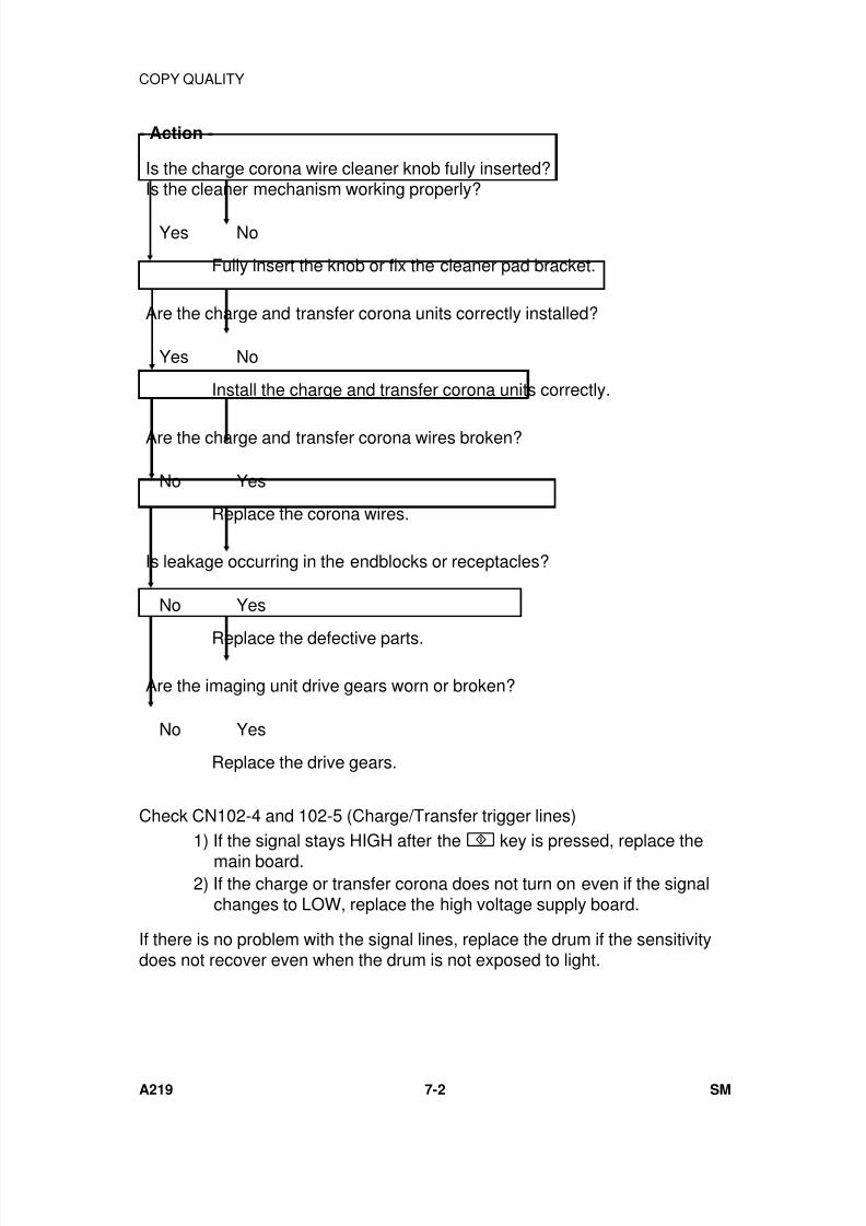
7/18/2019 A219 245 B019 4015 3813 Service
http://slidepdf.com/reader/full/a219-245-b019-4015-3813-service 229/372
- Action -
Is the charge corona wire cleaner knob fully inserted?Is the cleaner mechanism working properly?
Yes No
Fully insert the knob or fix the cleaner pad bracket.
Are the charge and transfer corona units correctly installed?
Yes No
Install the charge and transfer corona units correctly.
Are the charge and transfer corona wires broken?
No Yes
Replace the corona wires.
Is leakage occurring in the endblocks or receptacles?
No Yes
Replace the defective parts.
Are the imaging unit drive gears worn or broken?
No Yes
Replace the drive gears.
Check CN102-4 and 102-5 (Charge/Transfer trigger lines)1) If the signal stays HIGH after the key is pressed, replace the
main board.2) If the charge or transfer corona does not turn on even if the signal
changes to LOW, replace the high voltage supply board.
If there is no problem with the signal lines, replace the drum if the sensitivitydoes not recover even when the drum is not exposed to light.
COPY QUALITY
A219 7-2 SM
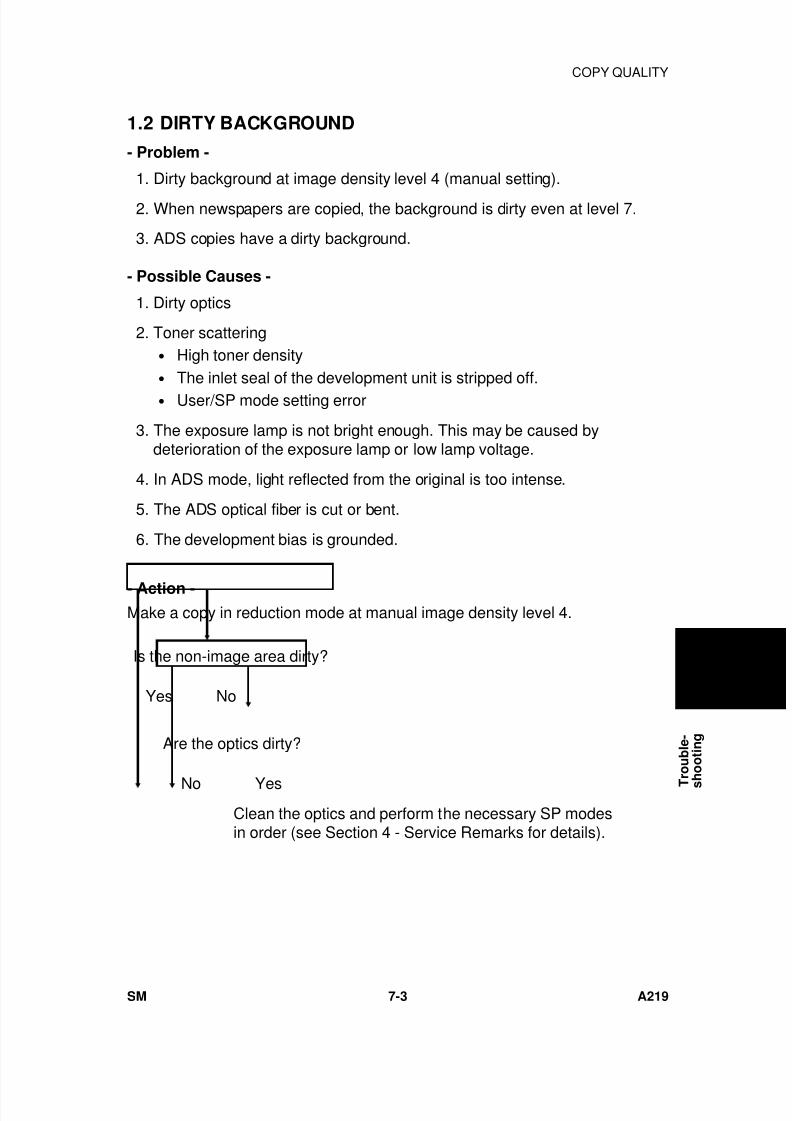
7/18/2019 A219 245 B019 4015 3813 Service
http://slidepdf.com/reader/full/a219-245-b019-4015-3813-service 230/372
1.2 DIRTY BACKGROUND
- Problem -
1. Dirty background at image density level 4 (manual setting).
2. When newspapers are copied, the background is dirty even at level 7.
3. ADS copies have a dirty background.
- Possible Causes -
1. Dirty optics
2. Toner scattering• High toner density• The inlet seal of the development unit is stripped off.• User/SP mode setting error
3. The exposure lamp is not bright enough. This may be caused bydeterioration of the exposure lamp or low lamp voltage.
4. In ADS mode, light reflected from the original is too intense.
5. The ADS optical fiber is cut or bent.
6. The development bias is grounded.
- Action -
Make a copy in reduction mode at manual image density level 4.
Is the non-image area dirty?
Yes No
Are the optics dirty?
No Yes
Clean the optics and perform the necessary SP modesin order (see Section 4 - Service Remarks for details).
T r
o u b l e -
s h
o o t i n g
COPY QUALITY
SM 7-3 A219
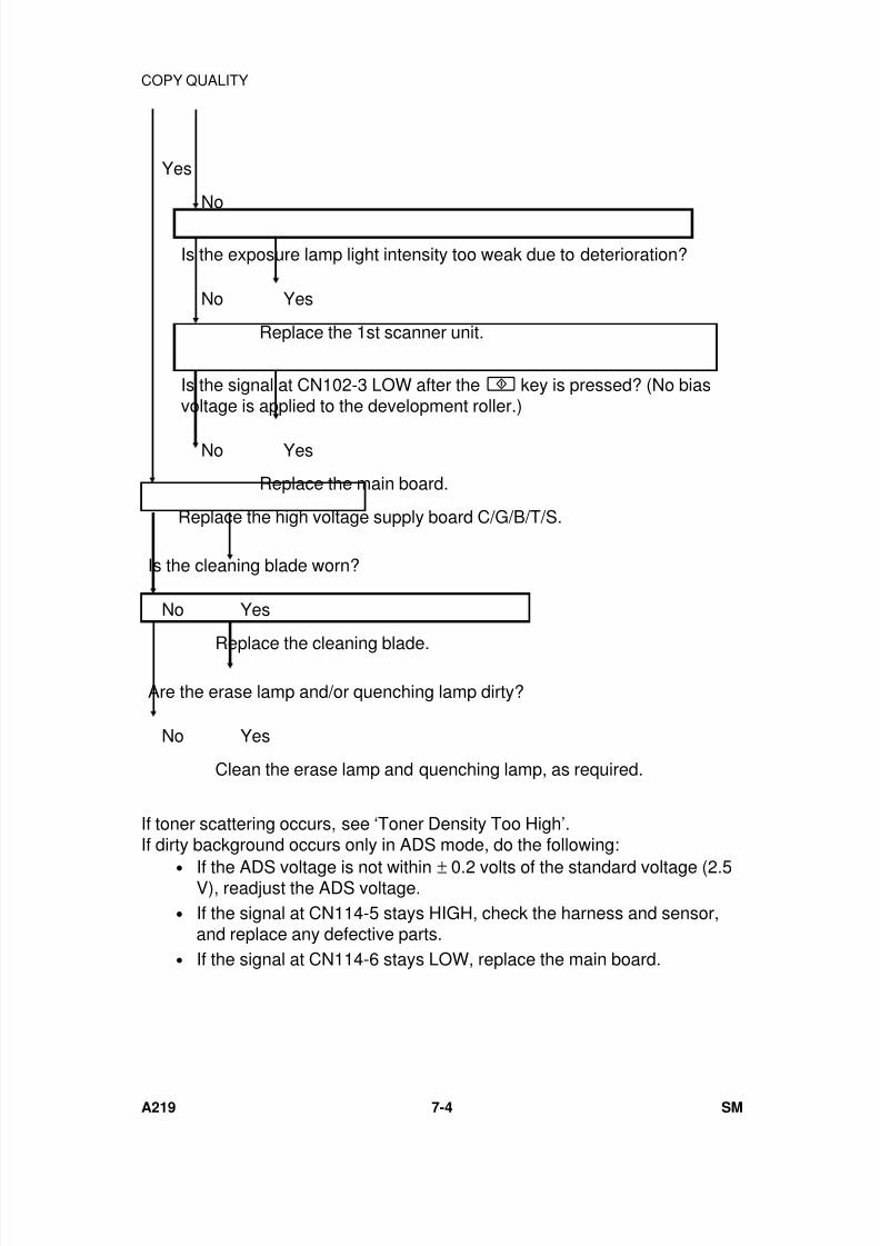
7/18/2019 A219 245 B019 4015 3813 Service
http://slidepdf.com/reader/full/a219-245-b019-4015-3813-service 231/372
Yes
No
Is the exposure lamp light intensity too weak due to deterioration?
No Yes
Replace the 1st scanner unit.
Is the signal at CN102-3 LOW after the key is pressed? (No biasvoltage is applied to the development roller.)
No Yes
Replace the main board.
Replace the high voltage supply board C/G/B/T/S.
Is the cleaning blade worn?
No Yes
Replace the cleaning blade.
Are the erase lamp and/or quenching lamp dirty?
No Yes
Clean the erase lamp and quenching lamp, as required.
If toner scattering occurs, see ‘Toner Density Too High’.If dirty background occurs only in ADS mode, do the following:
• If the ADS voltage is not within ± 0.2 volts of the standard voltage (2.5V), readjust the ADS voltage.
• If the signal at CN114-5 stays HIGH, check the harness and sensor,and replace any defective parts.
• If the signal at CN114-6 stays LOW, replace the main board.
COPY QUALITY
A219 7-4 SM
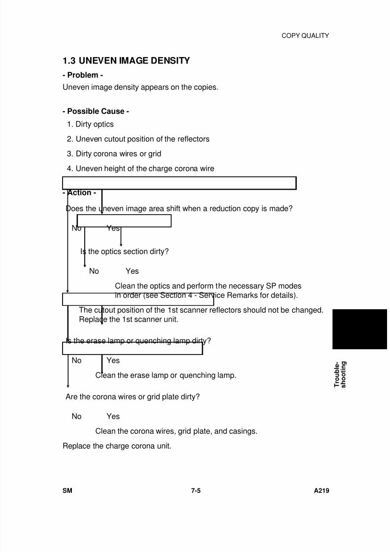
7/18/2019 A219 245 B019 4015 3813 Service
http://slidepdf.com/reader/full/a219-245-b019-4015-3813-service 232/372
1.3 UNEVEN IMAGE DENSITY
- Problem -
Uneven image density appears on the copies.
- Possible Cause -
1. Dirty optics
2. Uneven cutout position of the reflectors
3. Dirty corona wires or grid
4. Uneven height of the charge corona wire
- Action -
Does the uneven image area shift when a reduction copy is made?
No Yes
Is the optics section dirty?
No Yes
Clean the optics and perform the necessary SP modesin order (see Section 4 - Service Remarks for details).
The cutout position of the 1st scanner reflectors should not be changed.Replace the 1st scanner unit.
Is the erase lamp or quenching lamp dirty?
No Yes
Clean the erase lamp or quenching lamp.
Are the corona wires or grid plate dirty?
No Yes
Clean the corona wires, grid plate, and casings.
Replace the charge corona unit.
T r
o u b l e -
s h
o o t i n g
COPY QUALITY
SM 7-5 A219
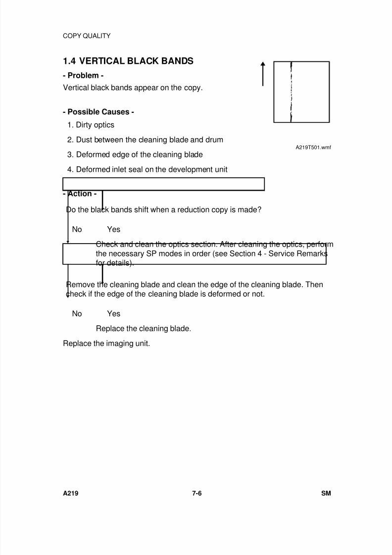
7/18/2019 A219 245 B019 4015 3813 Service
http://slidepdf.com/reader/full/a219-245-b019-4015-3813-service 233/372
1.4 VERTICAL BLACK BANDS
- Problem -
Vertical black bands appear on the copy.
- Possible Causes -
1. Dirty optics
2. Dust between the cleaning blade and drum
3. Deformed edge of the cleaning blade
4. Deformed inlet seal on the development unit
- Action -
Do the black bands shift when a reduction copy is made?
No Yes
Check and clean the optics section. After cleaning the optics, performthe necessary SP modes in order (see Section 4 - Service Remarksfor details).
Remove the cleaning blade and clean the edge of the cleaning blade. Thencheck if the edge of the cleaning blade is deformed or not.
No Yes
Replace the cleaning blade.
Replace the imaging unit.
A219T501.wmf
COPY QUALITY
A219 7-6 SM
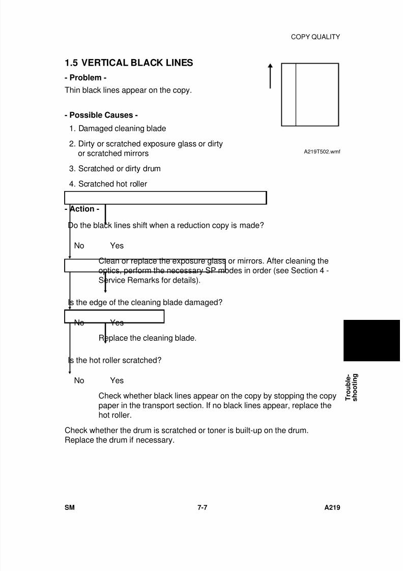
7/18/2019 A219 245 B019 4015 3813 Service
http://slidepdf.com/reader/full/a219-245-b019-4015-3813-service 234/372
1.5 VERTICAL BLACK LINES
- Problem -
Thin black lines appear on the copy.
- Possible Causes -
1. Damaged cleaning blade
2. Dirty or scratched exposure glass or dirtyor scratched mirrors
3. Scratched or dirty drum
4. Scratched hot roller
- Action -
Do the black lines shift when a reduction copy is made?
No Yes
Clean or replace the exposure glass or mirrors. After cleaning theoptics, perform the necessary SP modes in order (see Section 4 -Service Remarks for details).
Is the edge of the cleaning blade damaged?
No Yes
Replace the cleaning blade.
Is the hot roller scratched?
No Yes
Check whether black lines appear on the copy by stopping the copypaper in the transport section. If no black lines appear, replace thehot roller.
Check whether the drum is scratched or toner is built-up on the drum.Replace the drum if necessary.
A219T502.wmf
T r
o u b l e -
s h
o o t i n g
COPY QUALITY
SM 7-7 A219

7/18/2019 A219 245 B019 4015 3813 Service
http://slidepdf.com/reader/full/a219-245-b019-4015-3813-service 235/372
1.6 VERTICAL WHITE LINES OR BANDS-1 (DULL ORBLURRED)
- Problem -
Dull or blurred white lines appear on the copy.
- Possible Causes -
1. Dirty or deteriorated charge corona wire
2. Dirty or deformed grid plate
3. Damp or deformed inlet seal on the development unit
- Action -
Are the charge corona wires or grid plate dirty?
No Yes
Clean the charge corona wires or grid plate.
Is the grid plate or the charge corona wire deteriorated or deformed?
No Yes
Replace the charge corona unit.
Replace the imaging unit.
A219T503.wmf
COPY QUALITY
A219 7-8 SM
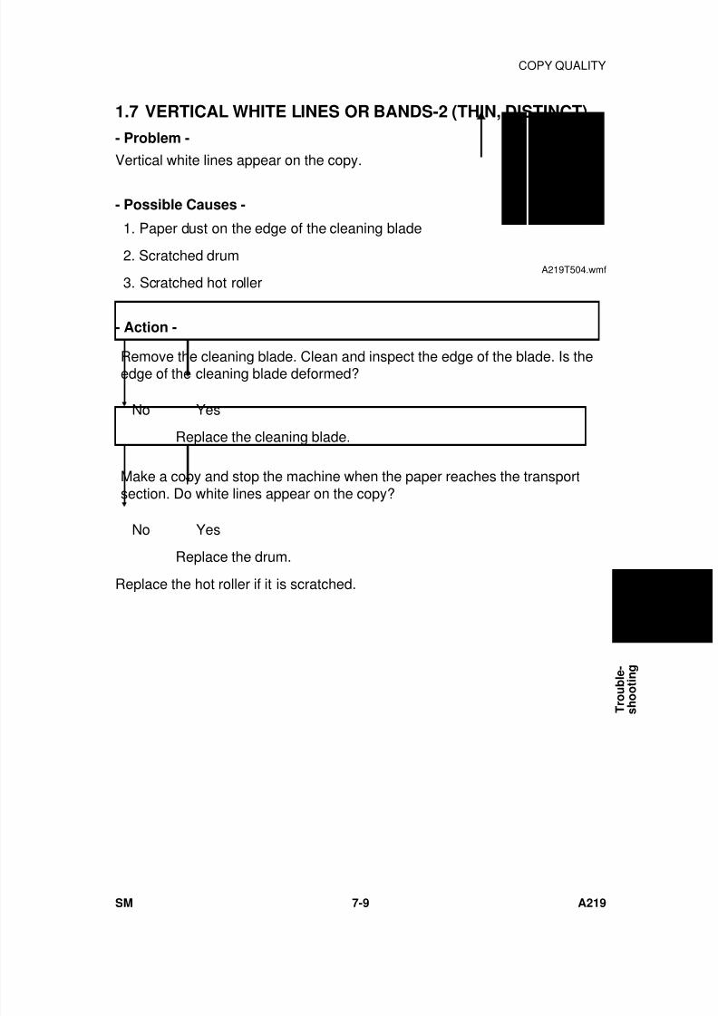
7/18/2019 A219 245 B019 4015 3813 Service
http://slidepdf.com/reader/full/a219-245-b019-4015-3813-service 236/372
1.7 VERTICAL WHITE LINES OR BANDS-2 (THIN, DISTINCT)
- Problem -
Vertical white lines appear on the copy.
- Possible Causes -
1. Paper dust on the edge of the cleaning blade
2. Scratched drum
3. Scratched hot roller
- Action -
Remove the cleaning blade. Clean and inspect the edge of the blade. Is theedge of the cleaning blade deformed?
No Yes
Replace the cleaning blade.
Make a copy and stop the machine when the paper reaches the transportsection. Do white lines appear on the copy?
No YesReplace the drum.
Replace the hot roller if it is scratched.
A219T504.wmf
T r
o u b l e -
s h
o o t i n g
COPY QUALITY
SM 7-9 A219
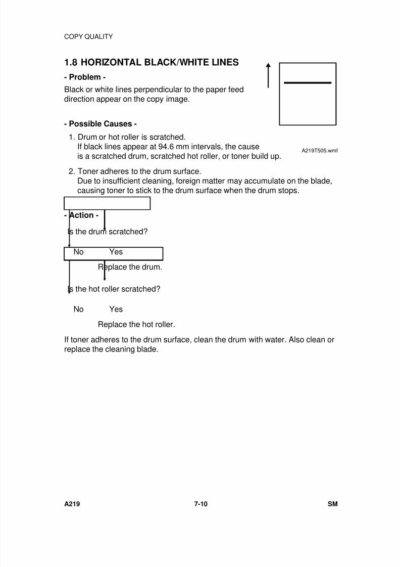
7/18/2019 A219 245 B019 4015 3813 Service
http://slidepdf.com/reader/full/a219-245-b019-4015-3813-service 237/372
1.8 HORIZONTAL BLACK/WHITE LINES
- Problem -
Black or white lines perpendicular to the paper feed
direction appear on the copy image.
- Possible Causes -
1. Drum or hot roller is scratched.If black lines appear at 94.6 mm intervals, the causeis a scratched drum, scratched hot roller, or toner build up.
2. Toner adheres to the drum surface.Due to insufficient cleaning, foreign matter may accumulate on the blade,causing toner to stick to the drum surface when the drum stops.
- Action -
Is the drum scratched?
No Yes
Replace the drum.
Is the hot roller scratched?
No Yes
Replace the hot roller.
If toner adheres to the drum surface, clean the drum with water. Also clean orreplace the cleaning blade.
A219T505.wmf
COPY QUALITY
A219 7-10 SM
7/18/2019 A219 245 B019 4015 3813 Service
http://slidepdf.com/reader/full/a219-245-b019-4015-3813-service 238/372
1.9 JITTER
- Problem -
Jitter appears on the copy.
- Possible Causes -
1. Drum not turning smoothly
2. Scanner not moving smoothly
- Action -
Does the jitter interval change when a reduction copy is made?
Yes No
Check drum drive mechanisms such as the drum drive gears and drumpulleys.
No Good
Reinstall them correctly or replace the defective parts.
Are the scanner drive belts correctly installed?
Yes No
Reinstall them correctly or replace the defective parts.
Does the voltage at CN103-2 through 5 on the main board stay at 24 voltswhen the key is pressed?
24 volts Not always 24 volts
Replace the scanner motor or check the scanner operation.
Replace the main board.
T r
o u b l e -
s h
o o t i n g
COPY QUALITY
SM 7-11 A219
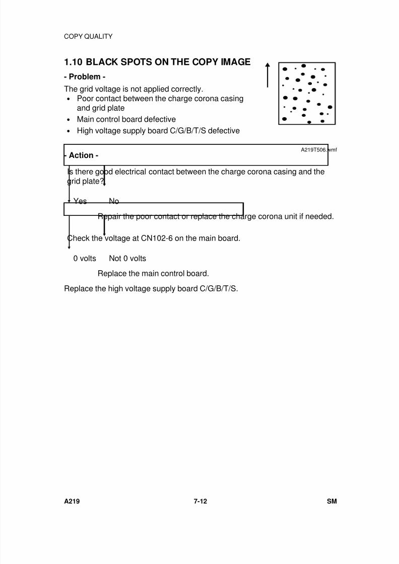
7/18/2019 A219 245 B019 4015 3813 Service
http://slidepdf.com/reader/full/a219-245-b019-4015-3813-service 239/372
1.10 BLACK SPOTS ON THE COPY IMAGE
- Problem -
The grid voltage is not applied correctly.• Poor contact between the charge corona casing
and grid plate• Main control board defective• High voltage supply board C/G/B/T/S defective
- Action -
Is there good electrical contact between the charge corona casing and thegrid plate?
Yes No
Repair the poor contact or replace the charge corona unit if needed.
Check the voltage at CN102-6 on the main board.
0 volts Not 0 volts
Replace the main control board.
Replace the high voltage supply board C/G/B/T/S.
A219T506.wmf
COPY QUALITY
A219 7-12 SM
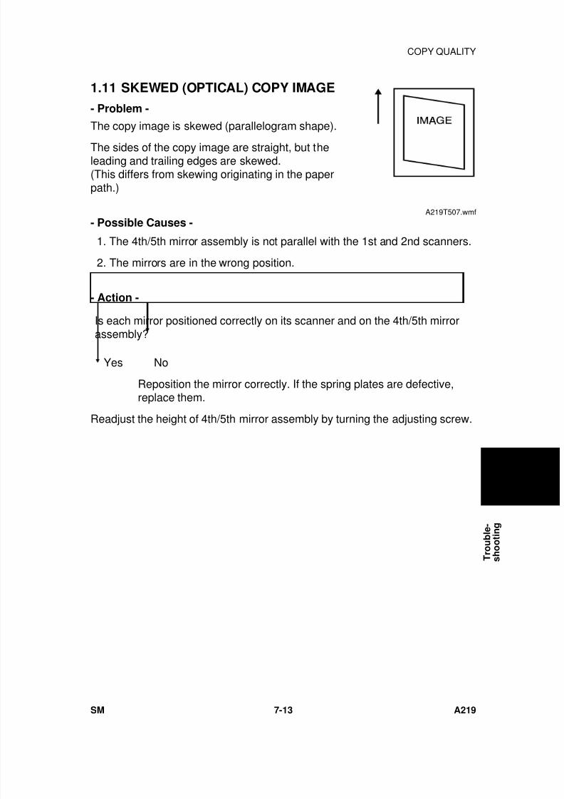
7/18/2019 A219 245 B019 4015 3813 Service
http://slidepdf.com/reader/full/a219-245-b019-4015-3813-service 240/372
1.11 SKEWED (OPTICAL) COPY IMAGE
- Problem -
The copy image is skewed (parallelogram shape).
The sides of the copy image are straight, but theleading and trailing edges are skewed.(This differs from skewing originating in the paperpath.)
- Possible Causes -
1. The 4th/5th mirror assembly is not parallel with the 1st and 2nd scanners.
2. The mirrors are in the wrong position.
- Action -
Is each mirror positioned correctly on its scanner and on the 4th/5th mirrorassembly?
Yes No
Reposition the mirror correctly. If the spring plates are defective,replace them.
Readjust the height of 4th/5th mirror assembly by turning the adjusting screw.
A219T507.wmf
T r
o u b l e -
s h
o o t i n g
COPY QUALITY
SM 7-13 A219
7/18/2019 A219 245 B019 4015 3813 Service
http://slidepdf.com/reader/full/a219-245-b019-4015-3813-service 241/372
1.12 TONER DENSITY ON COPIES TOO HIGH
- Problem -
1. Dirty background appears on the copy.
2. The image density of black solid areas is too high.
- Possible Causes -
1. The toner supply motor keeps on turning continuously.
2. SP30 (Toner Supply Mode Selection) has been changed from the defaultsetting.
3. The main control board is defective.
4. The charge corona current is too low.
5. Some SP or UP modes have been changed that would lead to thisproblem.
6. TD sensor defective.
- Action -
Has an abnormal TD sensor condition occurred?
No Yes
See the "Abnormal Condition in Toner Density Detection" section.
Clean the optics section and the area around the drum. Make a few skyshot copies and then readjust the light intensity and the ADS voltage.
Does the toner supply motor turn even though there is sufficient toner in the
development unit?
No Yes
Check the voltage at CN106-1 on the main board.
24 volts 0 volt
COPY QUALITY
A219 7-14 SM
7/18/2019 A219 245 B019 4015 3813 Service
http://slidepdf.com/reader/full/a219-245-b019-4015-3813-service 242/372
24 volts 0 volt
Replace the main board.
Replace the toner supply motor.
No
Is SP30 (Toner Supply Mode Selection) set to the default value?
Yes No
Change the value to the default setting "0".
Is the grid voltage correct?
Yes No
Readjust the grid voltage.
Clean the optics section and around the imaging unit.Perform the necessary SP modes in order (see Section 4 - Service Remarksfor details).
Check the related SP mode settings (SP30, 31, 32, 33, 34, 35, 36, 38, 48, 53,
54 and 62).Change the settings to lean towards the lighter side.
T r
o u b l e -
s h
o o t i n g
COPY QUALITY
SM 7-15 A219
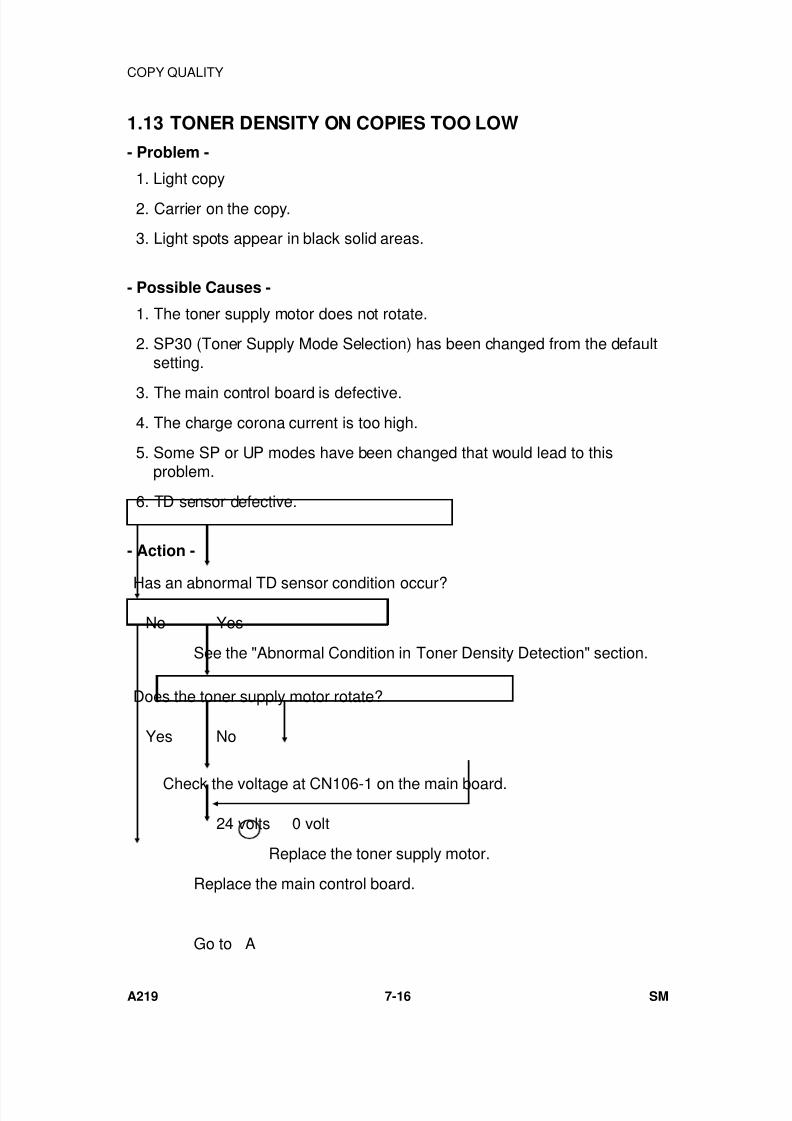
7/18/2019 A219 245 B019 4015 3813 Service
http://slidepdf.com/reader/full/a219-245-b019-4015-3813-service 243/372
1.13 TONER DENSITY ON COPIES TOO LOW
- Problem -
1. Light copy
2. Carrier on the copy.
3. Light spots appear in black solid areas.
- Possible Causes -
1. The toner supply motor does not rotate.
2. SP30 (Toner Supply Mode Selection) has been changed from the defaultsetting.
3. The main control board is defective.
4. The charge corona current is too high.
5. Some SP or UP modes have been changed that would lead to thisproblem.
6. TD sensor defective.
- Action -
Has an abnormal TD sensor condition occur?
No Yes
See the "Abnormal Condition in Toner Density Detection" section.
Does the toner supply motor rotate?
Yes No
Check the voltage at CN106-1 on the main board.
24 volts 0 volt
Replace the toner supply motor.
Replace the main control board.
Go to A
COPY QUALITY
A219 7-16 SM
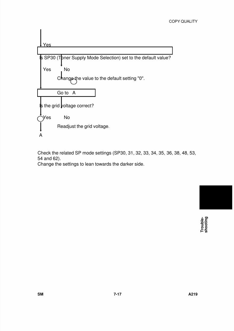
7/18/2019 A219 245 B019 4015 3813 Service
http://slidepdf.com/reader/full/a219-245-b019-4015-3813-service 244/372
Yes
Is SP30 (Toner Supply Mode Selection) set to the default value?
Yes No
Change the value to the default setting "0".
Go to A
Is the grid voltage correct?
Yes No
Readjust the grid voltage.
A
Check the related SP mode settings (SP30, 31, 32, 33, 34, 35, 36, 38, 48, 53,54 and 62).Change the settings to lean towards the darker side.
T r
o u b l e -
s h
o o t i n g
COPY QUALITY
SM 7-17 A219
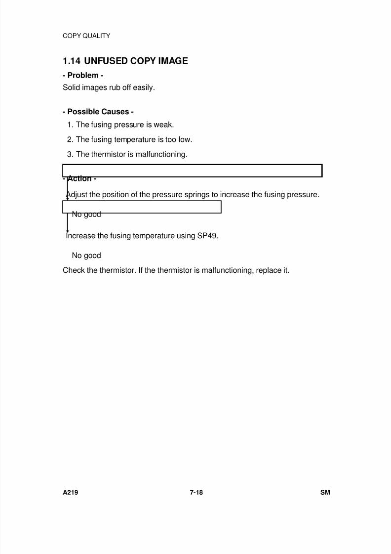
7/18/2019 A219 245 B019 4015 3813 Service
http://slidepdf.com/reader/full/a219-245-b019-4015-3813-service 245/372
1.14 UNFUSED COPY IMAGE
- Problem -
Solid images rub off easily.
- Possible Causes -
1. The fusing pressure is weak.
2. The fusing temperature is too low.
3. The thermistor is malfunctioning.
- Action -
Adjust the position of the pressure springs to increase the fusing pressure.
No good
Increase the fusing temperature using SP49.
No good
Check the thermistor. If the thermistor is malfunctioning, replace it.
COPY QUALITY
A219 7-18 SM
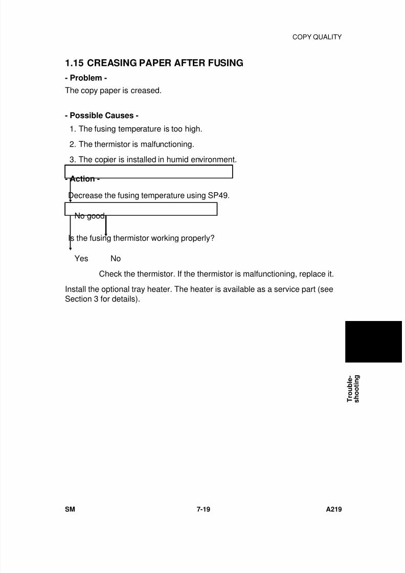
7/18/2019 A219 245 B019 4015 3813 Service
http://slidepdf.com/reader/full/a219-245-b019-4015-3813-service 246/372
1.15 CREASING PAPER AFTER FUSING
- Problem -
The copy paper is creased.
- Possible Causes -
1. The fusing temperature is too high.
2. The thermistor is malfunctioning.
3. The copier is installed in humid environment.
- Action -
Decrease the fusing temperature using SP49.
No good
Is the fusing thermistor working properly?
Yes No
Check the thermistor. If the thermistor is malfunctioning, replace it.
Install the optional tray heater. The heater is available as a service part (see
Section 3 for details).
T r
o u b l e -
s h
o o t i n g
COPY QUALITY
SM 7-19 A219
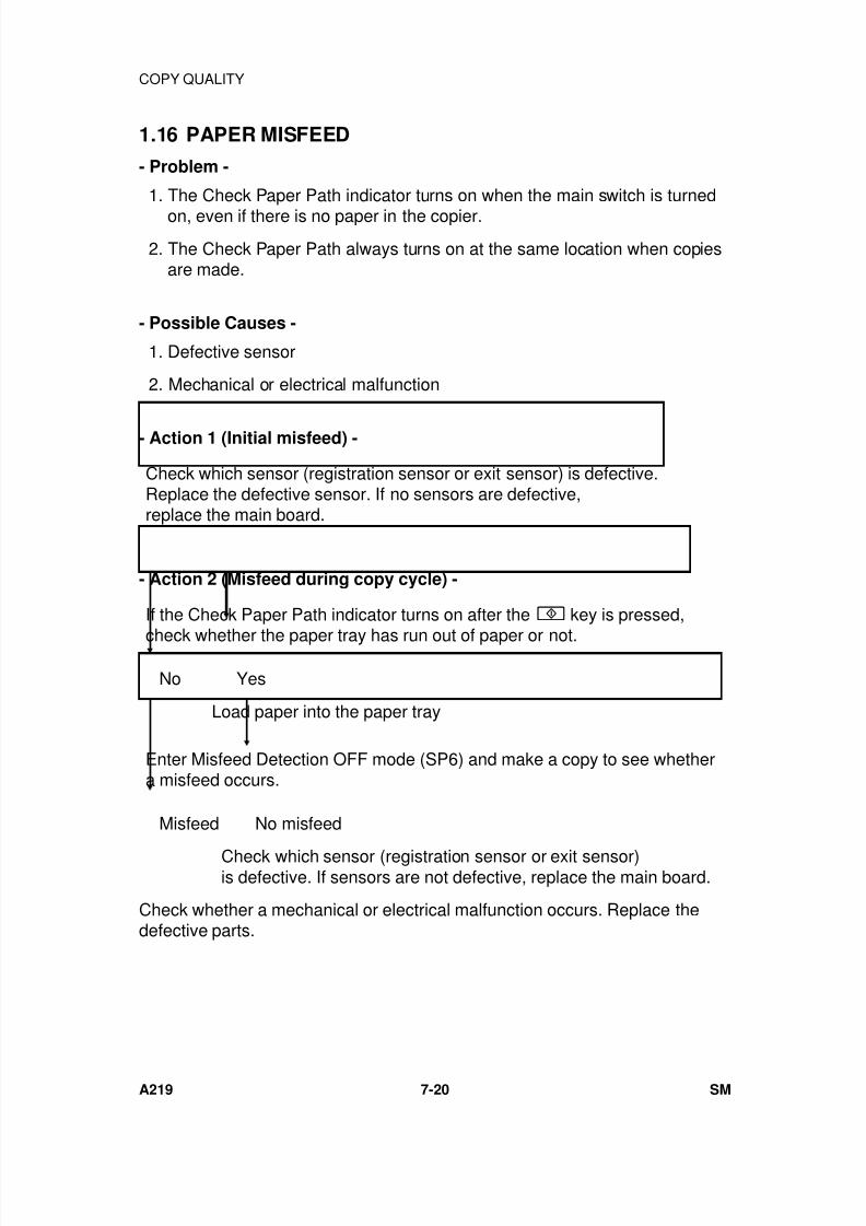
7/18/2019 A219 245 B019 4015 3813 Service
http://slidepdf.com/reader/full/a219-245-b019-4015-3813-service 247/372
1.16 PAPER MISFEED
- Problem -
1. The Check Paper Path indicator turns on when the main switch is turned
on, even if there is no paper in the copier.
2. The Check Paper Path always turns on at the same location when copiesare made.
- Possible Causes -
1. Defective sensor
2. Mechanical or electrical malfunction
- Action 1 (Initial misfeed) -
Check which sensor (registration sensor or exit sensor) is defective.Replace the defective sensor. If no sensors are defective,replace the main board.
- Action 2 (Misfeed during copy cycle) -
If the Check Paper Path indicator turns on after the key is pressed,
check whether the paper tray has run out of paper or not.
No Yes
Load paper into the paper tray
Enter Misfeed Detection OFF mode (SP6) and make a copy to see whethera misfeed occurs.
Misfeed No misfeed
Check which sensor (registration sensor or exit sensor)is defective. If sensors are not defective, replace the main board.
Check whether a mechanical or electrical malfunction occurs. Replace thedefective parts.
COPY QUALITY
A219 7-20 SM
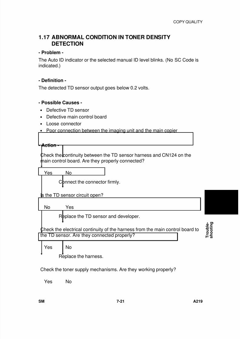
7/18/2019 A219 245 B019 4015 3813 Service
http://slidepdf.com/reader/full/a219-245-b019-4015-3813-service 248/372
1.17 ABNORMAL CONDITION IN TONER DENSITYDETECTION
- Problem -
The Auto ID indicator or the selected manual ID level blinks. (No SC Code isindicated.)
- Definition -
The detected TD sensor output goes below 0.2 volts.
- Possible Causes -
• Defective TD sensor
• Defective main control board• Loose connector• Poor connection between the imaging unit and the main copier
- Action -
Check the continuity between the TD sensor harness and CN124 on themain control board. Are they properly connected?
Yes No
Connect the connector firmly.
Is the TD sensor circuit open?
No Yes
Replace the TD sensor and developer.
Check the electrical continuity of the harness from the main control board to
the TD sensor. Are they connected properly?
Yes No
Replace the harness.
Check the toner supply mechanisms. Are they working properly?
Yes No
T r
o u b l e -
s h
o o t i n g
COPY QUALITY
SM 7-21 A219

7/18/2019 A219 245 B019 4015 3813 Service
http://slidepdf.com/reader/full/a219-245-b019-4015-3813-service 249/372
Yes No
Change or clean the defective parts.
Replace the main control board.
COPY QUALITY
A219 7-22 SM
7/18/2019 A219 245 B019 4015 3813 Service
http://slidepdf.com/reader/full/a219-245-b019-4015-3813-service 250/372
2. SERVICE CALL CONDITIONS
NOTE: 1) E-codes are displayed in the copy counter. The "E" and the "codenumber" are displayed alternatively.
2) To clear the service call condition, turn the main switch off and on.
3) When a fusing service call conditions occurs (example E52) , forsafety reasons they cannot be cleared by turning the main switchoff/on. The following procedure must be performed to clear theseservice call conditions.1. After repairing the machine, turn on the main switch.2. Enter SP mode 97.3. Turn the main switch off and on.
CODE #11 — EXPOSURE LAMP ERROR 1
- Definition -
• The feedback signal becomes higher than 4.2 volts (rms) for 1.0second when the exposure lamp is on.
• The feedback signal becomes higher than 1.0 volt (rms) for 1.0second when the exposure lamp is off.
- Possible Causes -
• Triac short circuit• Exposure lamp open• Thermofuse open
CODE #12 — EXPOSURE LAMP ERROR 2
- Definition -
• The feedback signal falls below 0.5 volt (rms) for 1.0 second when theexposure lamp is on.
• The exposure lamp stays on for longer than 25 seconds.
- Possible Causes -
• Defective ac drive/dc power supply board• Defective main control board• Defective power supply circuit
T r
o u b l e -
s h
o o t i n g
SERVICE CALL CONDITIONS
SM 7-23 A219
7/18/2019 A219 245 B019 4015 3813 Service
http://slidepdf.com/reader/full/a219-245-b019-4015-3813-service 251/372
CODE #13 — ZERO CROSS SIGNAL ERROR
- Definition -The CPU does not receive the zero cross signal within 2.0 seconds, orthe interval between zero cross signals is more than 2.0 seconds.
- Possible Causes -
• Defective main control board• Defective ac drive/dc power supply board• Zero cross line open• CN101 on the main control board or CN207 on the ac drive/dc power
supply board is not correctly connected.
SC CODE#14
- Definition -The detected current is neither 50 or 60 Hz.
- Possible Causes -
• Defective main Control Board• Defective AC Drive / DC Power Supply Board• Zero Cross line open• CN101 on the Main Conrol Board or CN207 on the AC Drive / DC
Power Supply Board is not correctly connected• Power line is not stable
* to Clear Service Code 14:• Turn the Main Power Switch "OFF" and "ON"
CODE #21 — SCANNER HOME POSITION ERROR 1
- Definition -The scanner home position sensor’s output remains LOW (de-actuated)for 10 seconds after the main switch is turned on, or the output remainsLOW (de-actuated) after the scanner returns during the copy process.
- Possible Causes -
• Defective home position sensor• Defective scanner drive motor• Defective main control board• Defective ac drive/dc power supply board• Defective scanner drive circuit
⇒
Rev. 8/29/97SERVICE CALL CONDITIONS
A219 7-24 SM
7/18/2019 A219 245 B019 4015 3813 Service
http://slidepdf.com/reader/full/a219-245-b019-4015-3813-service 252/372
CODE #22 — SCANNER HOME POSITION ERROR 2
- Definition -The scanner home position sensor’s output remains HIGH (actuated) for4.0 seconds after the main switch is turned on, or the output remainsHIGH (actuated) for 0.3 seconds after the scanner starts.
- Possible Causes -
• Defective home position sensor• Defective scanner drive motor• Defective main control board• Defective ac drive/dc power supply board• Defective scanner drive circuit• F2 on the ac drive/dc power supply board open (blown fuse).
CODE #2A — 4TH/5TH MIRROR HOME POSITION ERROR 1
- Definition -The 4th/5th mirror home position sensor’s output remains LOW for 10seconds after driving the 4th/5th mirror motor.
- Possible Causes -
• Defective 4th/5th mirror home position sensor• Defective 4th/5th mirror motor
• Defective 4th/5th mirror drive mechanism
CODE #2B 4TH/5TH MIRROR HOME POSITION ERROR 2
- Definition -The 4th/5th mirror home position sensor’s output remains HIGH for 10seconds after driving the 4th/5th mirror motor.
- Possible Causes -
• Defective 4th/5th mirror home position sensor• Defective 4th/5th mirror motor• Defective 4th/5th mirror drive mechanism• F2 on the ac drive/dc power supply board open (blown fuse)
Rev. 8/29/97
T r
o u b l e -
s h
o o t i n g
SERVICE CALL CONDITIONS
SM 7-25 A219
7/18/2019 A219 245 B019 4015 3813 Service
http://slidepdf.com/reader/full/a219-245-b019-4015-3813-service 253/372
CODE #28 — LENS HOME POSITION ERROR 1
- Definition -The lens home position sensor’s output remains LOW (de-actuated) for10 seconds after the unit moves to the home position.
- Possible Causes -
• Defective lens home position sensor• Defective lens drive motor• Defective main control board• Defective lens drive mechanism
CODE #29 — LENS HOME POSITION ERROR 2
- Definition -
The lens home position sensor’s output remains HIGH (actuated) for 10seconds after the unit leaves the home position.
- Possible Causes -
• Defective lens home position sensor• Defective lens drive motor• Defective main control board• Defective lens drive mechanism
CODE #40 — OPTICS THERMISTOR ERROR
-Definition-The optics thermistor is open.
- Possible Cause -
• Defective optics thermistor• Defective main control board• CN121 on the main control board is not correctly connected.
CODE #42 — HIGH VOLTAGE LEAKAGE
- Definition -The high voltage supply board detects the leakage and sends the leaksignal to the main control board for more than 1 second.
- Possible Causes -
• Transfer charge unit• High voltage supply board• Main control board (CN102-1)
Rev. 8/29/97SERVICE CALL CONDITIONS
A219 7-26 SM
7/18/2019 A219 245 B019 4015 3813 Service
http://slidepdf.com/reader/full/a219-245-b019-4015-3813-service 254/372
CODE #52 — FUSING ERROR 1
- Definition -The temperature detected by the thermistor does not reach 100°C within24 (NA) or 35 (EU) seconds after the main switch is turned on.To clear this error, refer to note 3 at the beginning of this chapter.
- Possible Causes -
• Defective fusing thermistor• Fusing lamp open• Defective ac drive/dc power supply board• Defective main control board• CN101 on the main control board or CN207 on the ac drive/dc power
supply board is not correctly connected.
CODE #53 — FUSING ERROR 2
- Definition -The temperature detected by the thermistor becomes higher than 255°C.To clear this error, refer to note 3 at the beginning of this chapter.
- Possible Causes -
• Thermistor short• Defective ac drive/dc power supply board•
Defective main control board• Fusing harness shorted• Triac short
CODE #54 — FUSING ERROR 3
- Definition -The fusing lamp stays on for longer than 38 (NA) or 57 (EU) secondswhile the main motor is off.To clear this error, refer to note 3 at the beginning of this chapter.
- Possible Causes -
• Main board• Defective ac drive/dc power supply board
T r
o u b l e -
s h
o o t i n g
SERVICE CALL CONDITIONS
SM 7-27 A219
7/18/2019 A219 245 B019 4015 3813 Service
http://slidepdf.com/reader/full/a219-245-b019-4015-3813-service 255/372
CODE #55 — FUSING ERROR 4
- Definition -
• The temperature value output by the thermistor has not changed at all
16 (NA) or 20 (EU) seconds after the main switch is turned on.• The temperature change detected by the thermistor is more than 20°C
within any one second after the 16 (NA) or 20 (EU) seconds warm uptime after the main switch is turned on.To clear this error, refer to note 3 at the beginning of this chapter.
- Possible Causes -
• Thermistor open• Defective main control board• Defective ac drive/dc power supply board
• Fusing lamp open• Poor thermistor connection
SERVICE CALL CONDITIONS
A219 7-28 SM
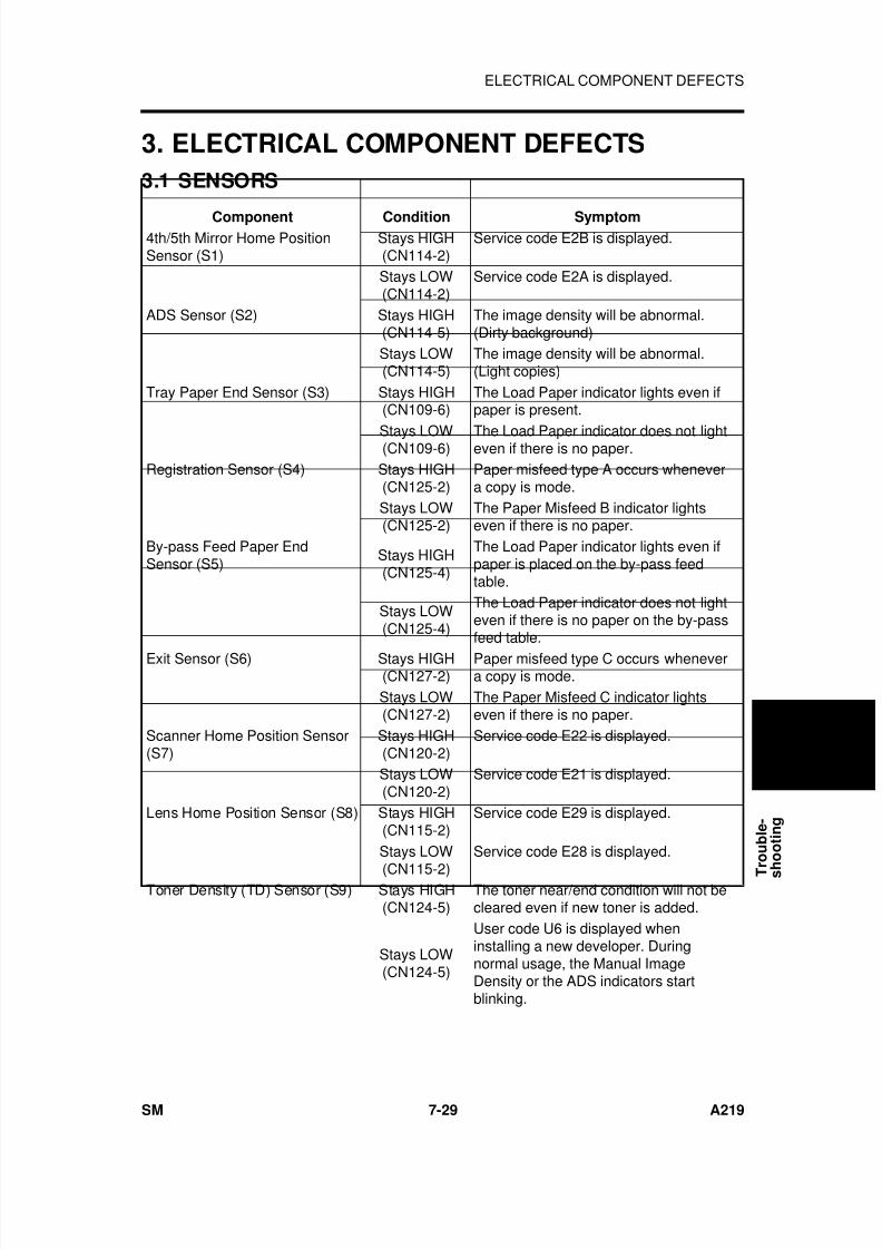
7/18/2019 A219 245 B019 4015 3813 Service
http://slidepdf.com/reader/full/a219-245-b019-4015-3813-service 256/372
3. ELECTRICAL COMPONENT DEFECTS
3.1 SENSORS
Component Condition Symptom4th/5th Mirror Home PositionSensor (S1)
Stays HIGH(CN114-2)
Service code E2B is displayed.
Stays LOW(CN114-2)
Service code E2A is displayed.
ADS Sensor (S2) Stays HIGH(CN114-5)
The image density will be abnormal.(Dirty background)
Stays LOW(CN114-5)
The image density will be abnormal.(Light copies)
Tray Paper End Sensor (S3) Stays HIGH(CN109-6)
The Load Paper indicator lights even ifpaper is present.
Stays LOW(CN109-6) The Load Paper indicator does not lighteven if there is no paper.Registration Sensor (S4) Stays HIGH
(CN125-2)Paper misfeed type A occurs whenevera copy is mode.
Stays LOW(CN125-2)
The Paper Misfeed B indicator lightseven if there is no paper.
By-pass Feed Paper EndSensor (S5)
Stays HIGH(CN125-4)
The Load Paper indicator lights even ifpaper is placed on the by-pass feedtable.
Stays LOW(CN125-4)
The Load Paper indicator does not lighteven if there is no paper on the by-passfeed table.
Exit Sensor (S6) Stays HIGH(CN127-2)
Paper misfeed type C occurs whenevera copy is mode.
Stays LOW(CN127-2)
The Paper Misfeed C indicator lightseven if there is no paper.
Scanner Home Position Sensor(S7)
Stays HIGH(CN120-2)
Service code E22 is displayed.
Stays LOW(CN120-2)
Service code E21 is displayed.
Lens Home Position Sensor (S8) Stays HIGH(CN115-2)
Service code E29 is displayed.
Stays LOW
(CN115-2)
Service code E28 is displayed.
Toner Density (TD) Sensor (S9) Stays HIGH(CN124-5)
The toner near/end condition will not becleared even if new toner is added.
Stays LOW(CN124-5)
User code U6 is displayed wheninstalling a new developer. Duringnormal usage, the Manual ImageDensity or the ADS indicators startblinking.
T r
o u b l e -
s h
o o t i n g
ELECTRICAL COMPONENT DEFECTS
SM 7-29 A219
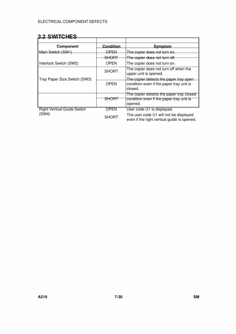
7/18/2019 A219 245 B019 4015 3813 Service
http://slidepdf.com/reader/full/a219-245-b019-4015-3813-service 257/372
3.2 SWITCHES
Component Condition Symptom
Main Switch (SW1) OPEN The copier does not turn on.
SHORT The copier does not turn off.Interlock Switch (SW2) OPEN The copier does not turn on.
SHORTThe copier does not turn off when theupper unit is opened.
Tray Paper Size Switch (SW3)OPEN
The copier detects the paper tray opencondition even if the paper tray unit isclosed.
SHORTThe copier detects the paper tray closedcondition even if the paper tray unit isopened.
Right Vertical Guide Switch
(SW4)
OPEN User code U1 is displayed.
SHORT The user code U1 will not be displayedeven if the right vertical guide is opened.
ELECTRICAL COMPONENT DEFECTS
A219 7-30 SM
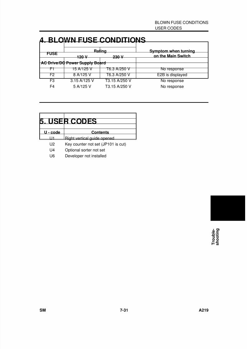
7/18/2019 A219 245 B019 4015 3813 Service
http://slidepdf.com/reader/full/a219-245-b019-4015-3813-service 258/372
4. BLOWN FUSE CONDITIONS
FUSERating Symptom when turning
on the Main Switch120 V 230 V
AC Drive/DC Power Supply Board
F1 15 A/125 V T6.3 A/250 V No responseF2 8 A/125 V T6.3 A/250 V E2B is displayedF3 3.15 A/125 V T3.15 A/250 V No responseF4 5 A/125 V T3.15 A/250 V No response
5. USER CODESU - code Contents
U1 Right vertical guide openedU2 Key counter not set (JP101 is cut)U4 Optional sorter not setU6 Developer not installed
USER CODES
T r
o u b l e -
s h
o o t i n g
BLOWN FUSE CONDITIONS
SM 7-31 A219

7/18/2019 A219 245 B019 4015 3813 Service
http://slidepdf.com/reader/full/a219-245-b019-4015-3813-service 259/372

7/18/2019 A219 245 B019 4015 3813 Service
http://slidepdf.com/reader/full/a219-245-b019-4015-3813-service 260/372
DOCUMENT FEEDER
A662

7/18/2019 A219 245 B019 4015 3813 Service
http://slidepdf.com/reader/full/a219-245-b019-4015-3813-service 261/372
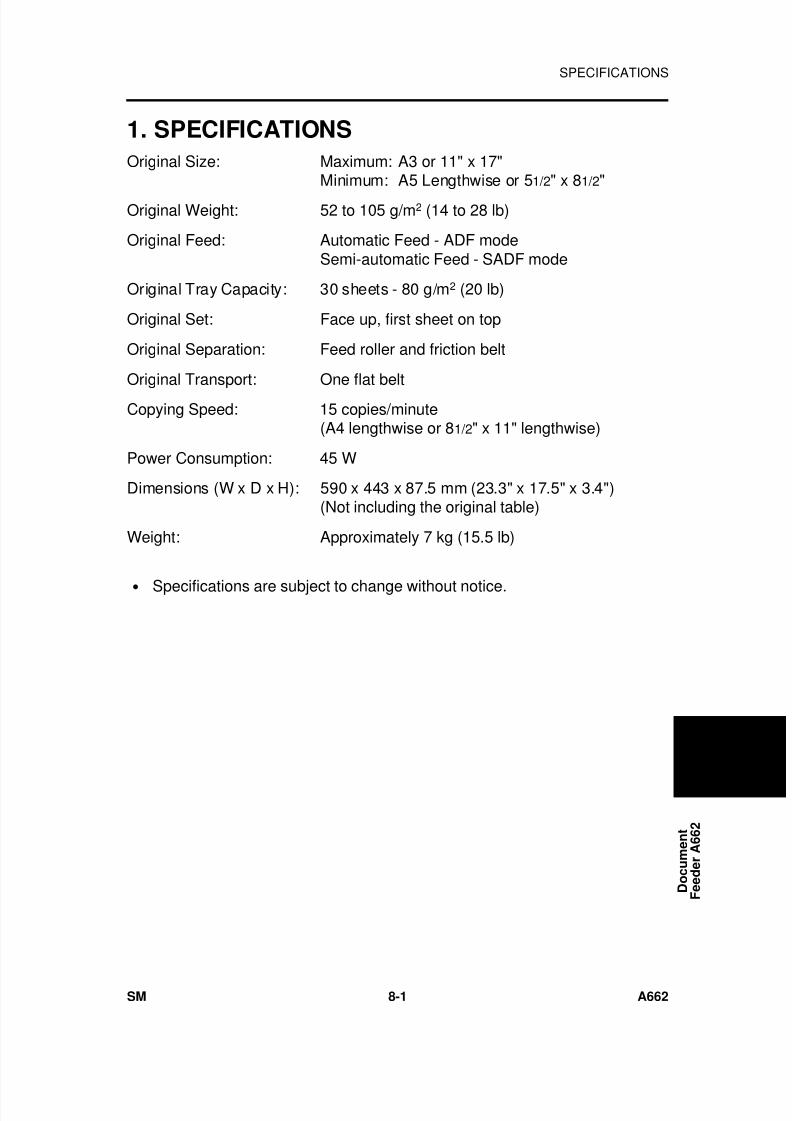
7/18/2019 A219 245 B019 4015 3813 Service
http://slidepdf.com/reader/full/a219-245-b019-4015-3813-service 262/372
1. SPECIFICATIONS
Original Size: Maximum: A3 or 11" x 17"Minimum: A5 Lengthwise or 51/2" x 81/2"
Original Weight: 52 to 105 g/m2 (14 to 28 lb)
Original Feed: Automatic Feed - ADF modeSemi-automatic Feed - SADF mode
Original Tray Capacity: 30 sheets - 80 g/m2 (20 lb)
Original Set: Face up, first sheet on top
Original Separation: Feed roller and friction belt
Original Transport: One flat belt
Copying Speed: 15 copies/minute(A4 lengthwise or 81/2" x 11" lengthwise)
Power Consumption: 45 W
Dimensions (W x D x H): 590 x 443 x 87.5 mm (23.3" x 17.5" x 3.4")(Not including the original table)
Weight: Approximately 7 kg (15.5 lb)
• Specifications are subject to change without notice.
D o c u m e n t
F e e d e r A 6 6 2
SPECIFICATIONS
SM 8-1 A662
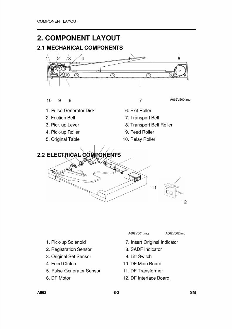
7/18/2019 A219 245 B019 4015 3813 Service
http://slidepdf.com/reader/full/a219-245-b019-4015-3813-service 263/372
2. COMPONENT LAYOUT
2.1 MECHANICAL COMPONENTS
2.2 ELECTRICAL COMPONENTS
1 2 3 4 65
78910 A662V500.img
1. Pulse Generator Disk
2. Friction Belt
3. Pick-up Lever
4. Pick-up Roller
5. Original Table
6. Exit Roller
7. Transport Belt
8. Transport Belt Roller
9. Feed Roller
10. Relay Roller
12 3
45 6
7 89
10
11
A662V501.img
12
A662V502.img
1. Pick-up Solenoid
2. Registration Sensor
3. Original Set Sensor
4. Feed Clutch
5. Pulse Generator Sensor
6. DF Motor
7. Insert Original Indicator
8. SADF Indicator
9. Lift Switch
10. DF Main Board
11. DF Transformer
12. DF Interface Board
COMPONENT LAYOUT
A662 8-2 SM
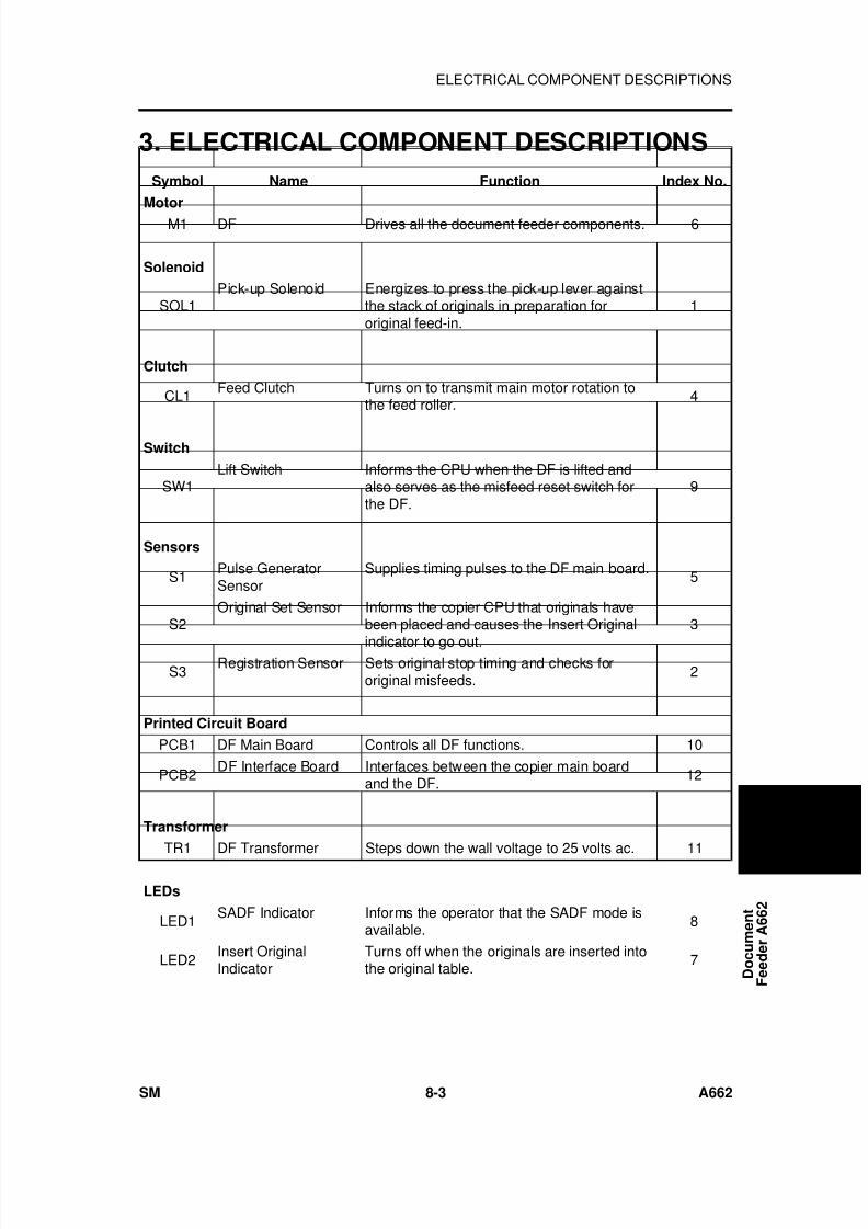
7/18/2019 A219 245 B019 4015 3813 Service
http://slidepdf.com/reader/full/a219-245-b019-4015-3813-service 264/372
3. ELECTRICAL COMPONENT DESCRIPTIONS
Symbol Name Function Index No.
Motor
M1 DF Drives all the document feeder components. 6
Solenoid
SOL1Pick-up Solenoid Energizes to press the pick-up lever against
the stack of originals in preparation fororiginal feed-in.
1
Clutch
CL1 Feed Clutch Turns on to transmit main motor rotation tothe feed roller.
4
Switch
SW1Lift Switch Informs the CPU when the DF is lifted and
also serves as the misfeed reset switch forthe DF.
9
Sensors
S1Pulse GeneratorSensor
Supplies timing pulses to the DF main board.5
S2Original Set Sensor Informs the copier CPU that originals have
been placed and causes the Insert Original
indicator to go out.
3
S3Registration Sensor Sets original stop timing and checks for
original misfeeds.2
Printed Circuit Board
PCB1 DF Main Board Controls all DF functions. 10
PCB2DF Interface Board Interfaces between the copier main board
and the DF.12
Transformer
TR1 DF Transformer Steps down the wall voltage to 25 volts ac. 11
LEDs
LED1SADF Indicator Informs the operator that the SADF mode is
available.8
LED2Insert OriginalIndicator
Turns off when the originals are inserted intothe original table.
7 D o c u m e n t
F e e d e r A 6 6 2
ELECTRICAL COMPONENT DESCRIPTIONS
SM 8-3 A662
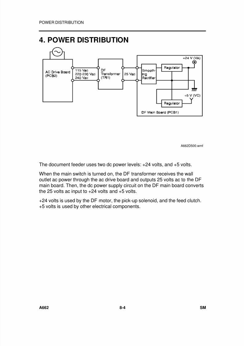
7/18/2019 A219 245 B019 4015 3813 Service
http://slidepdf.com/reader/full/a219-245-b019-4015-3813-service 265/372
4. POWER DISTRIBUTION
The document feeder uses two dc power levels: +24 volts, and +5 volts.
When the main switch is turned on, the DF transformer receives the wall
outlet ac power through the ac drive board and outputs 25 volts ac to the DFmain board. Then, the dc power supply circuit on the DF main board convertsthe 25 volts ac input to +24 volts and +5 volts.
+24 volts is used by the DF motor, the pick-up solenoid, and the feed clutch.+5 volts is used by other electrical components.
A662D500.wmf
POWER DISTRIBUTION
A662 8-4 SM
7/18/2019 A219 245 B019 4015 3813 Service
http://slidepdf.com/reader/full/a219-245-b019-4015-3813-service 266/372
5. BASIC OPERATION
When the main switch is turned on, the DF CPU sends the "DF installed"signal to the copier CPU. Receiving this signal, the copier CPU recognizes
that the document feeder is installed and sends the "DF confirmed" signal tothe DF CPU.
When originals are placed on the original table, the Insert Original indicatorturns off and the DF CPU sends the "original set" signal to the copier CPU toinform that the originals have been set.
When the Start key is pressed, the copier CPU sends the "feed-in" signal tothe document feeder. On receipt of this signal, the DF CPU energizes the DFmotor, then the pick-up solenoid and feed clutch to feed in the bottom sheetof the original stack onto the exposure glass. The pick-up solenoid, and the
feed clutch remain energized until the original’s leading edge reaches theregistration sensor. The DF motor turns off shortly after the original’s trailingedge passes the registration sensor. Then, the DF motor pauses andreverses for a moment to align the edge of the original with the scale.
Then the scanner starts to move, (scanner start timing does not depend onthe progress of the original through the DF; it starts at a fixed time after theStart key is pressed). When the scanner reaches the return position, thecopier CPU sends the "original change" signal to the DF CPU in order to feedout the current original and feed in the next original.
D o c u m e n t
F e e d e r A 6 6 2
BASIC OPERATION
SM 8-5 A662
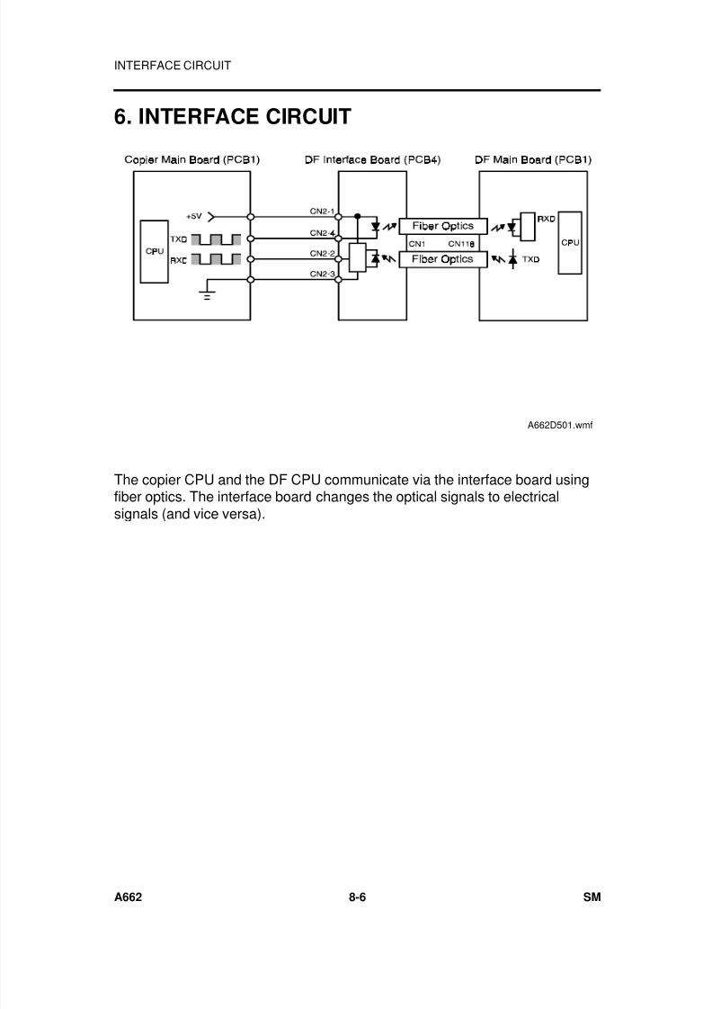
7/18/2019 A219 245 B019 4015 3813 Service
http://slidepdf.com/reader/full/a219-245-b019-4015-3813-service 267/372
6. INTERFACE CIRCUIT
The copier CPU and the DF CPU communicate via the interface board usingfiber optics. The interface board changes the optical signals to electricalsignals (and vice versa).
A662D501.wmf
INTERFACE CIRCUIT
A662 8-6 SM
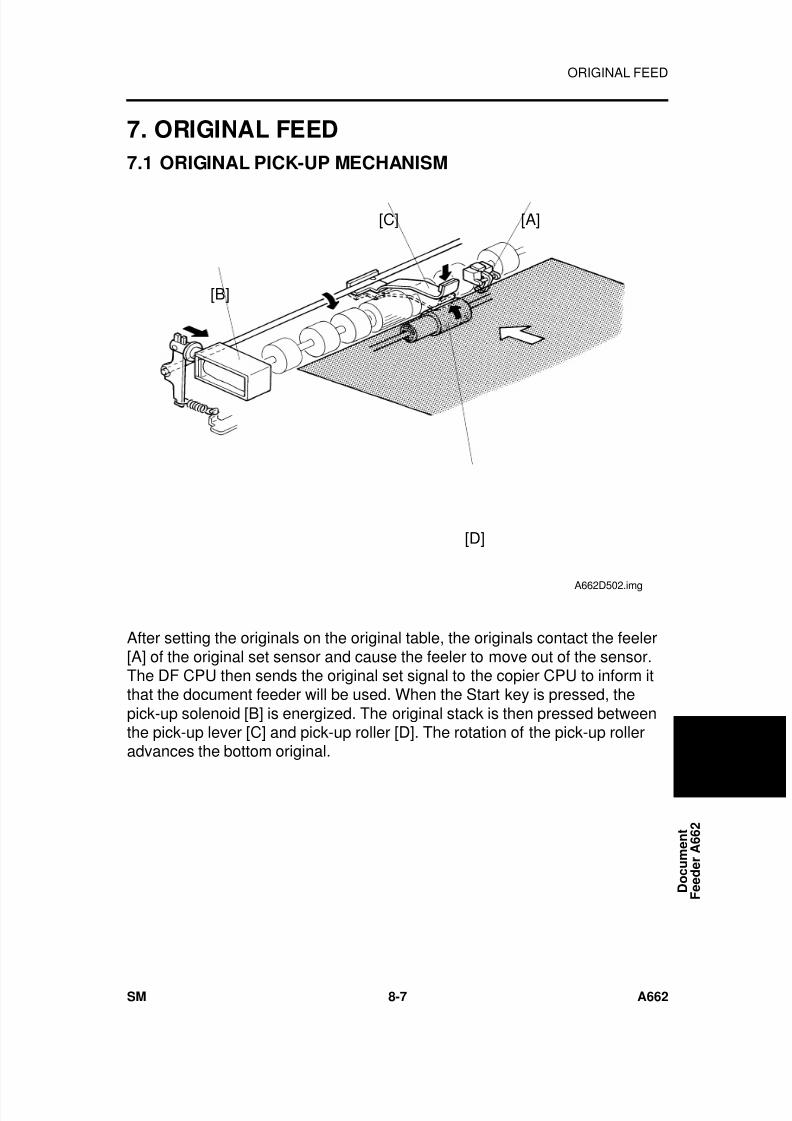
7/18/2019 A219 245 B019 4015 3813 Service
http://slidepdf.com/reader/full/a219-245-b019-4015-3813-service 268/372
7. ORIGINAL FEED
7.1 ORIGINAL PICK-UP MECHANISM
After setting the originals on the original table, the originals contact the feeler[A] of the original set sensor and cause the feeler to move out of the sensor.The DF CPU then sends the original set signal to the copier CPU to inform itthat the document feeder will be used. When the Start key is pressed, thepick-up solenoid [B] is energized. The original stack is then pressed betweenthe pick-up lever [C] and pick-up roller [D]. The rotation of the pick-up rolleradvances the bottom original.
[B]
[C] [A]
[D]
A662D502.img
D o c u m e n t
F e e d e r A 6 6 2
ORIGINAL FEED
SM 8-7 A662
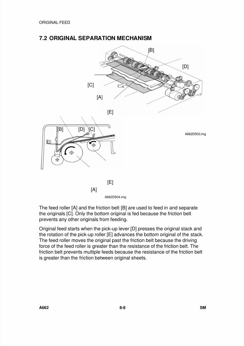
7/18/2019 A219 245 B019 4015 3813 Service
http://slidepdf.com/reader/full/a219-245-b019-4015-3813-service 269/372
7.2 ORIGINAL SEPARATION MECHANISM
The feed roller [A] and the friction belt [B] are used to feed in and separatethe originals [C]. Only the bottom original is fed because the friction beltprevents any other originals from feeding.
Original feed starts when the pick-up lever [D] presses the original stack andthe rotation of the pick-up roller [E] advances the bottom original of the stack.
The feed roller moves the original past the friction belt because the drivingforce of the feed roller is greater than the resistance of the friction belt. Thefriction belt prevents multiple feeds because the resistance of the friction beltis greater than the friction between original sheets.
[A]
[B]
[D]
[E]
[C]
A662D503.img
[A][E]
[C][D][B]
A662D504.img
ORIGINAL FEED
A662 8-8 SM
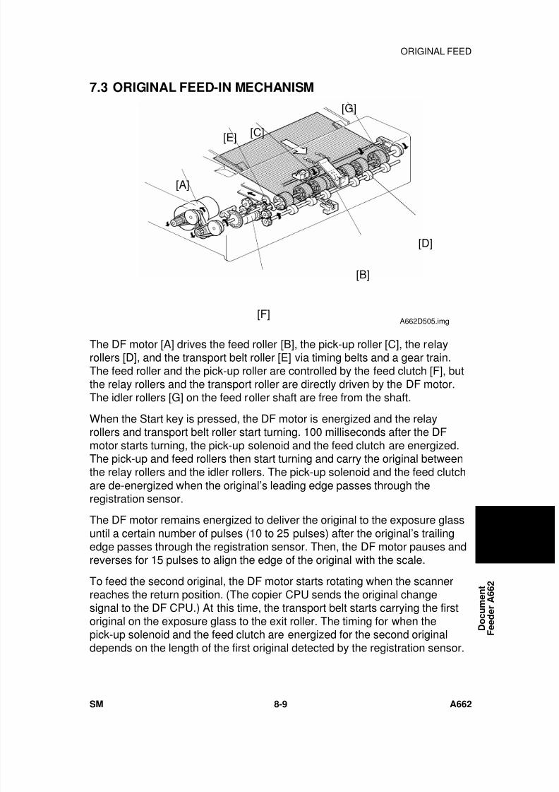
7/18/2019 A219 245 B019 4015 3813 Service
http://slidepdf.com/reader/full/a219-245-b019-4015-3813-service 270/372
7.3 ORIGINAL FEED-IN MECHANISM
The DF motor [A] drives the feed roller [B], the pick-up roller [C], the relayrollers [D], and the transport belt roller [E] via timing belts and a gear train.The feed roller and the pick-up roller are controlled by the feed clutch [F], butthe relay rollers and the transport roller are directly driven by the DF motor.The idler rollers [G] on the feed roller shaft are free from the shaft.
When the Start key is pressed, the DF motor is energized and the relayrollers and transport belt roller start turning. 100 milliseconds after the DFmotor starts turning, the pick-up solenoid and the feed clutch are energized.The pick-up and feed rollers then start turning and carry the original betweenthe relay rollers and the idler rollers. The pick-up solenoid and the feed clutchare de-energized when the original’s leading edge passes through theregistration sensor.
The DF motor remains energized to deliver the original to the exposure glassuntil a certain number of pulses (10 to 25 pulses) after the original’s trailing
edge passes through the registration sensor. Then, the DF motor pauses andreverses for 15 pulses to align the edge of the original with the scale.
To feed the second original, the DF motor starts rotating when the scannerreaches the return position. (The copier CPU sends the original changesignal to the DF CPU.) At this time, the transport belt starts carrying the firstoriginal on the exposure glass to the exit roller. The timing for when thepick-up solenoid and the feed clutch are energized for the second originaldepends on the length of the first original detected by the registration sensor.
[A]
[E] [C]
[G]
[D]
[B]
[F]A662D505.img
D o c u m e n t
F e e d e r A 6 6 2
ORIGINAL FEED
SM 8-9 A662
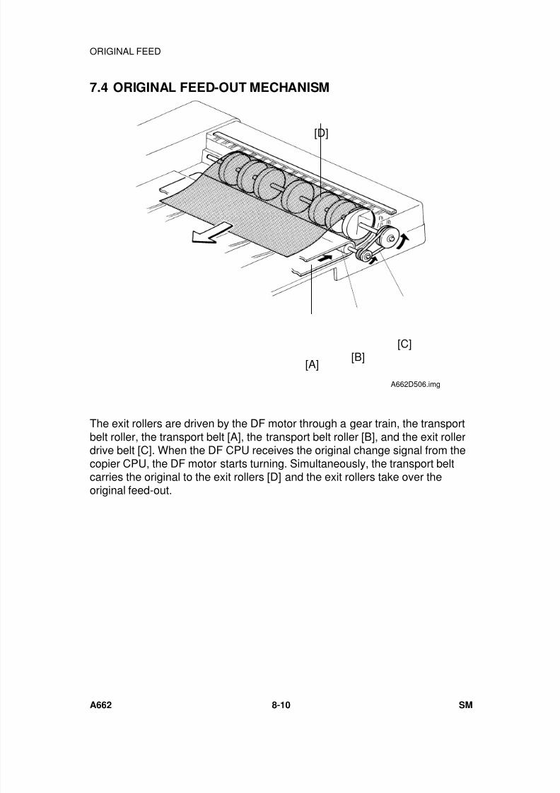
7/18/2019 A219 245 B019 4015 3813 Service
http://slidepdf.com/reader/full/a219-245-b019-4015-3813-service 271/372
7.4 ORIGINAL FEED-OUT MECHANISM
The exit rollers are driven by the DF motor through a gear train, the transportbelt roller, the transport belt [A], the transport belt roller [B], and the exit rollerdrive belt [C]. When the DF CPU receives the original change signal from thecopier CPU, the DF motor starts turning. Simultaneously, the transport beltcarries the original to the exit rollers [D] and the exit rollers take over theoriginal feed-out.
[D]
[A][B]
[C]
A662D506.img
ORIGINAL FEED
A662 8-10 SM
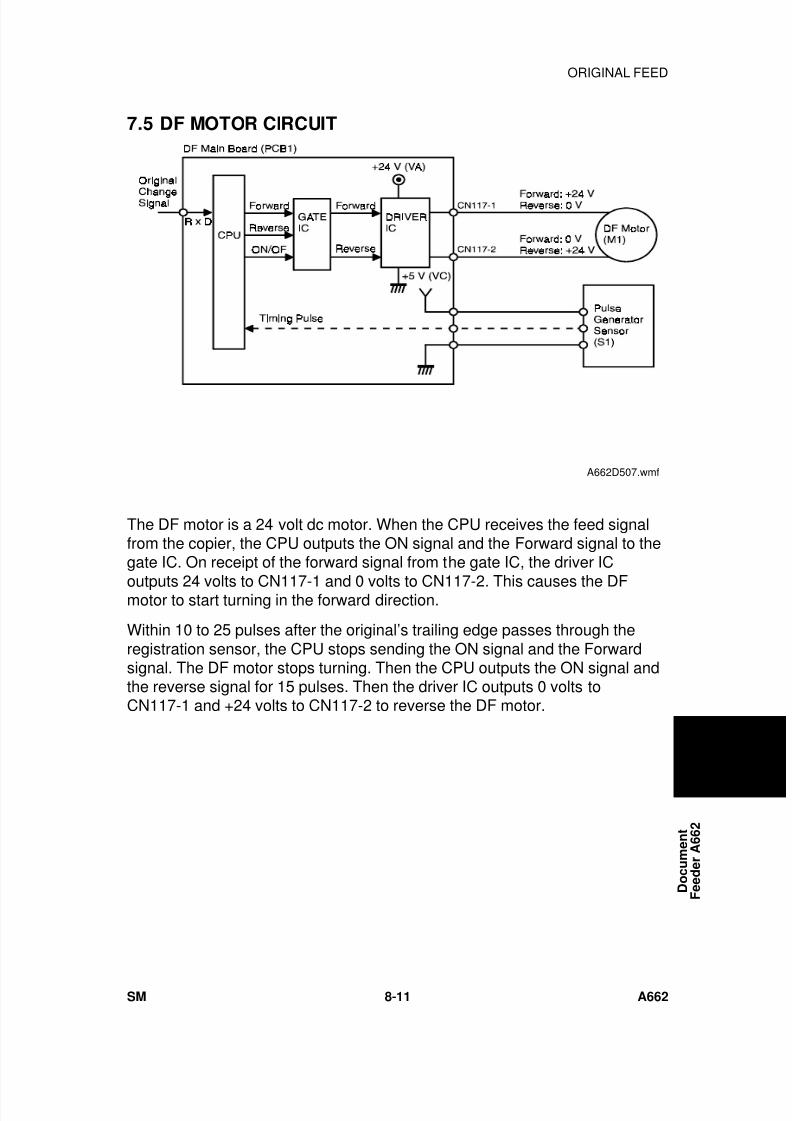
7/18/2019 A219 245 B019 4015 3813 Service
http://slidepdf.com/reader/full/a219-245-b019-4015-3813-service 272/372
7.5 DF MOTOR CIRCUIT
The DF motor is a 24 volt dc motor. When the CPU receives the feed signalfrom the copier, the CPU outputs the ON signal and the Forward signal to thegate IC. On receipt of the forward signal from the gate IC, the driver IC
outputs 24 volts to CN117-1 and 0 volts to CN117-2. This causes the DFmotor to start turning in the forward direction.
Within 10 to 25 pulses after the original’s trailing edge passes through theregistration sensor, the CPU stops sending the ON signal and the Forwardsignal. The DF motor stops turning. Then the CPU outputs the ON signal andthe reverse signal for 15 pulses. Then the driver IC outputs 0 volts toCN117-1 and +24 volts to CN117-2 to reverse the DF motor.
A662D507.wmf
D o c u m e n t
F e e d e r A 6 6 2
ORIGINAL FEED
SM 8-11 A662
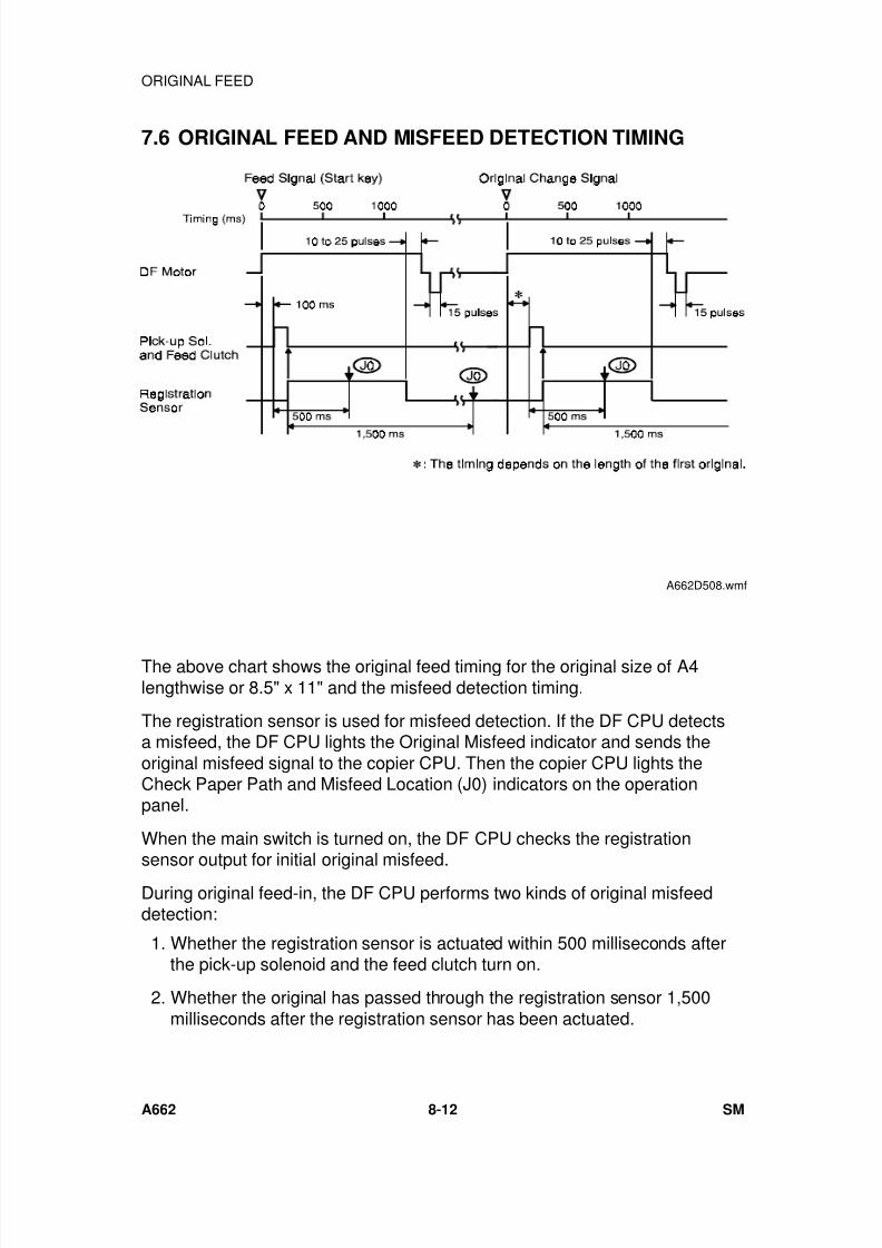
7/18/2019 A219 245 B019 4015 3813 Service
http://slidepdf.com/reader/full/a219-245-b019-4015-3813-service 273/372
7.6 ORIGINAL FEED AND MISFEED DETECTION TIMING
The above chart shows the original feed timing for the original size of A4lengthwise or 8.5" x 11" and the misfeed detection timing.
The registration sensor is used for misfeed detection. If the DF CPU detectsa misfeed, the DF CPU lights the Original Misfeed indicator and sends theoriginal misfeed signal to the copier CPU. Then the copier CPU lights theCheck Paper Path and Misfeed Location (J0) indicators on the operationpanel.
When the main switch is turned on, the DF CPU checks the registration
sensor output for initial original misfeed.During original feed-in, the DF CPU performs two kinds of original misfeeddetection:
1. Whether the registration sensor is actuated within 500 milliseconds afterthe pick-up solenoid and the feed clutch turn on.
2. Whether the original has passed through the registration sensor 1,500milliseconds after the registration sensor has been actuated.
A662D508.wmf
ORIGINAL FEED
A662 8-12 SM
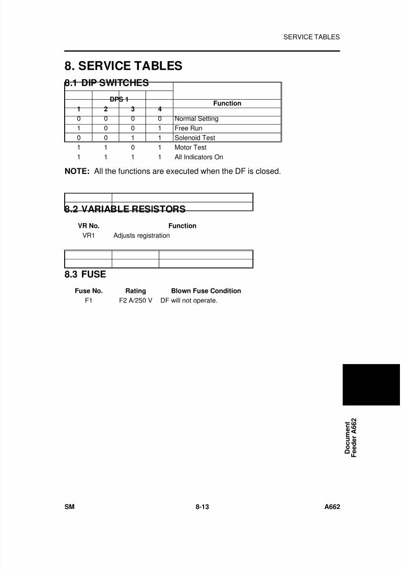
7/18/2019 A219 245 B019 4015 3813 Service
http://slidepdf.com/reader/full/a219-245-b019-4015-3813-service 274/372
8. SERVICE TABLES
8.1 DIP SWITCHES
DPS 1 Function1 2 3 4
0 0 0 0 Normal Setting1 0 0 1 Free Run0 0 1 1 Solenoid Test1 1 0 1 Motor Test1 1 1 1 All Indicators On
NOTE: All the functions are executed when the DF is closed.
8.2 VARIABLE RESISTORS
VR No. Function
VR1 Adjusts registration
8.3 FUSE
Fuse No. Rating Blown Fuse Condition
F1 F2 A/250 V DF will not operate.
D o c u m e n t
F e e d e r A 6 6 2
SERVICE TABLES
SM 8-13 A662
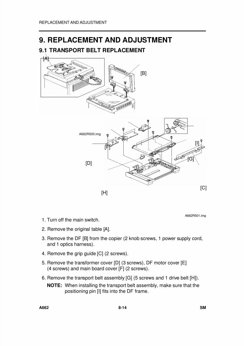
7/18/2019 A219 245 B019 4015 3813 Service
http://slidepdf.com/reader/full/a219-245-b019-4015-3813-service 275/372
9. REPLACEMENT AND ADJUSTMENT
9.1 TRANSPORT BELT REPLACEMENT
1. Turn off the main switch.
2. Remove the original table [A].
3. Remove the DF [B] from the copier (2 knob screws, 1 power supply cord,and 1 optics harness).
4. Remove the grip guide [C] (2 screws).
5. Remove the transformer cover [D] (3 screws), DF motor cover [E](4 screws) and main board cover [F] (2 screws).
6. Remove the transport belt assembly [G] (5 screws and 1 drive belt [H]).
NOTE: When installing the transport belt assembly, make sure that thepositioning pin [I] fits into the DF frame.
[A]
[B]
A662R500.img
[I]
[C]
[G]
[E]
[F]
[D]
[H]
A662R501.img
REPLACEMENT AND ADJUSTMENT
A662 8-14 SM
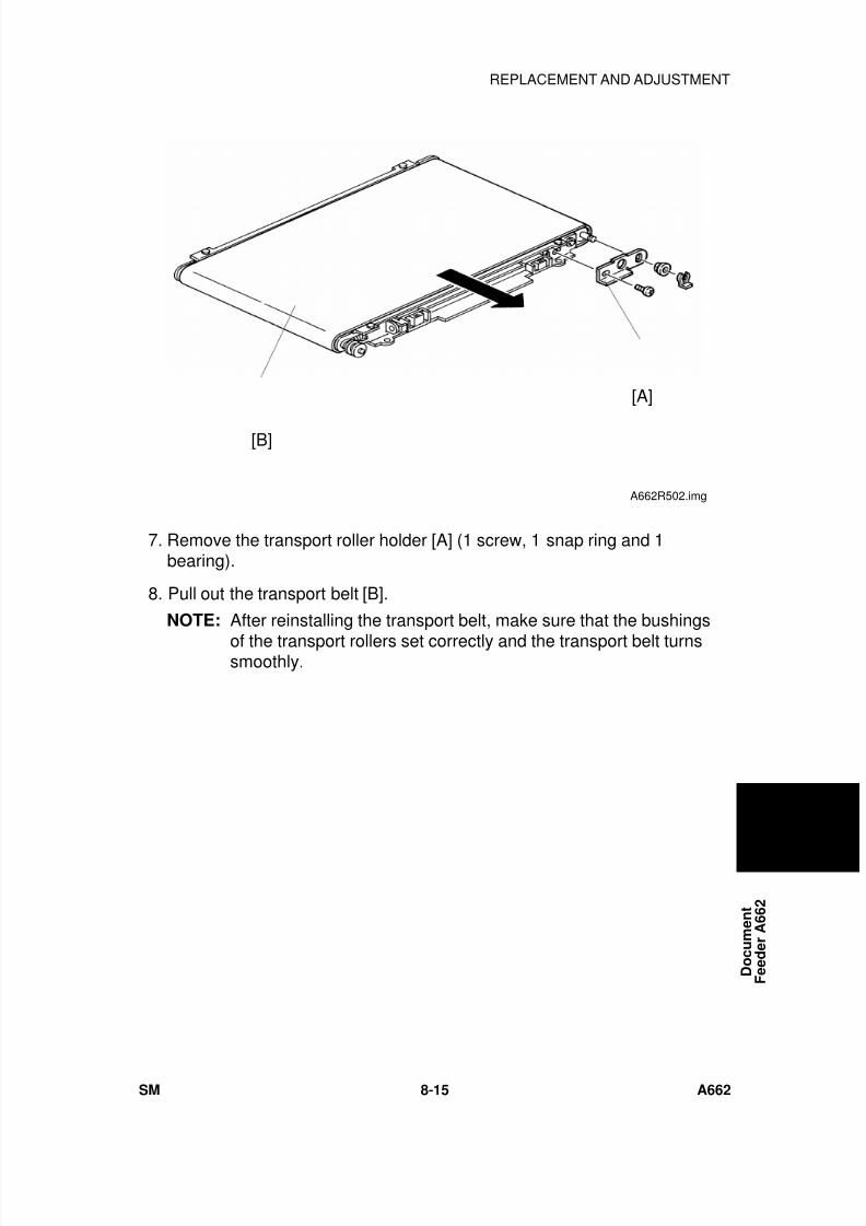
7/18/2019 A219 245 B019 4015 3813 Service
http://slidepdf.com/reader/full/a219-245-b019-4015-3813-service 276/372
7. Remove the transport roller holder [A] (1 screw, 1 snap ring and 1bearing).
8. Pull out the transport belt [B].
NOTE: After reinstalling the transport belt, make sure that the bushings
of the transport rollers set correctly and the transport belt turnssmoothly.
[B]
[A]
A662R502.img
D o c u m e n t
F e e d e r A 6 6 2
REPLACEMENT AND ADJUSTMENT
SM 8-15 A662
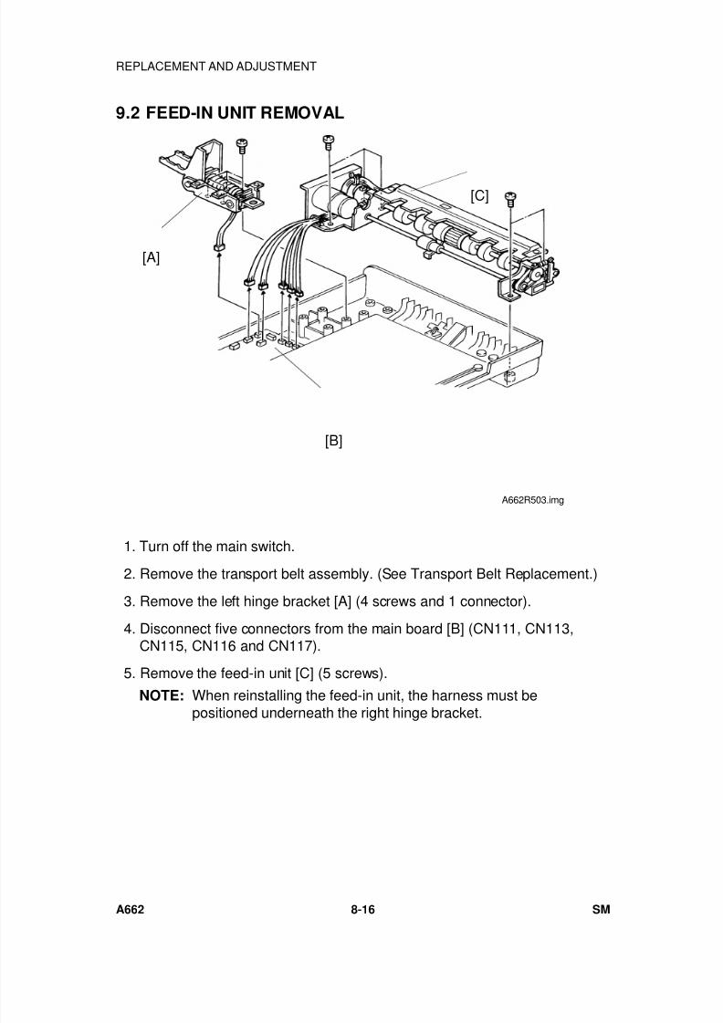
7/18/2019 A219 245 B019 4015 3813 Service
http://slidepdf.com/reader/full/a219-245-b019-4015-3813-service 277/372
9.2 FEED-IN UNIT REMOVAL
1. Turn off the main switch.
2. Remove the transport belt assembly. (See Transport Belt Replacement.)
3. Remove the left hinge bracket [A] (4 screws and 1 connector).
4. Disconnect five connectors from the main board [B] (CN111, CN113,CN115, CN116 and CN117).
5. Remove the feed-in unit [C] (5 screws).
NOTE: When reinstalling the feed-in unit, the harness must be
positioned underneath the right hinge bracket.
[C]
[A]
[B]
A662R503.img
REPLACEMENT AND ADJUSTMENT
A662 8-16 SM
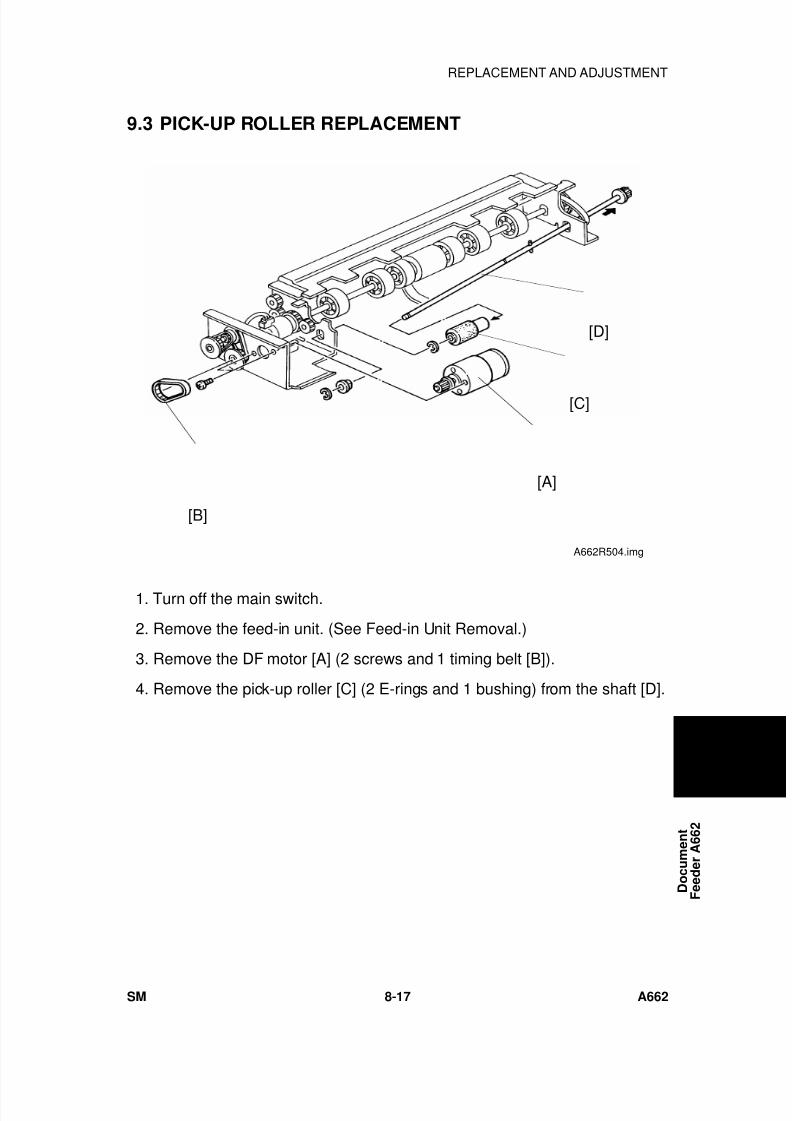
7/18/2019 A219 245 B019 4015 3813 Service
http://slidepdf.com/reader/full/a219-245-b019-4015-3813-service 278/372
9.3 PICK-UP ROLLER REPLACEMENT
1. Turn off the main switch.
2. Remove the feed-in unit. (See Feed-in Unit Removal.)
3. Remove the DF motor [A] (2 screws and 1 timing belt [B]).
4. Remove the pick-up roller [C] (2 E-rings and 1 bushing) from the shaft [D].
[B]
[A]
[C]
[D]
A662R504.img
D o c u m e n t
F e e d e r A 6 6 2
REPLACEMENT AND ADJUSTMENT
SM 8-17 A662
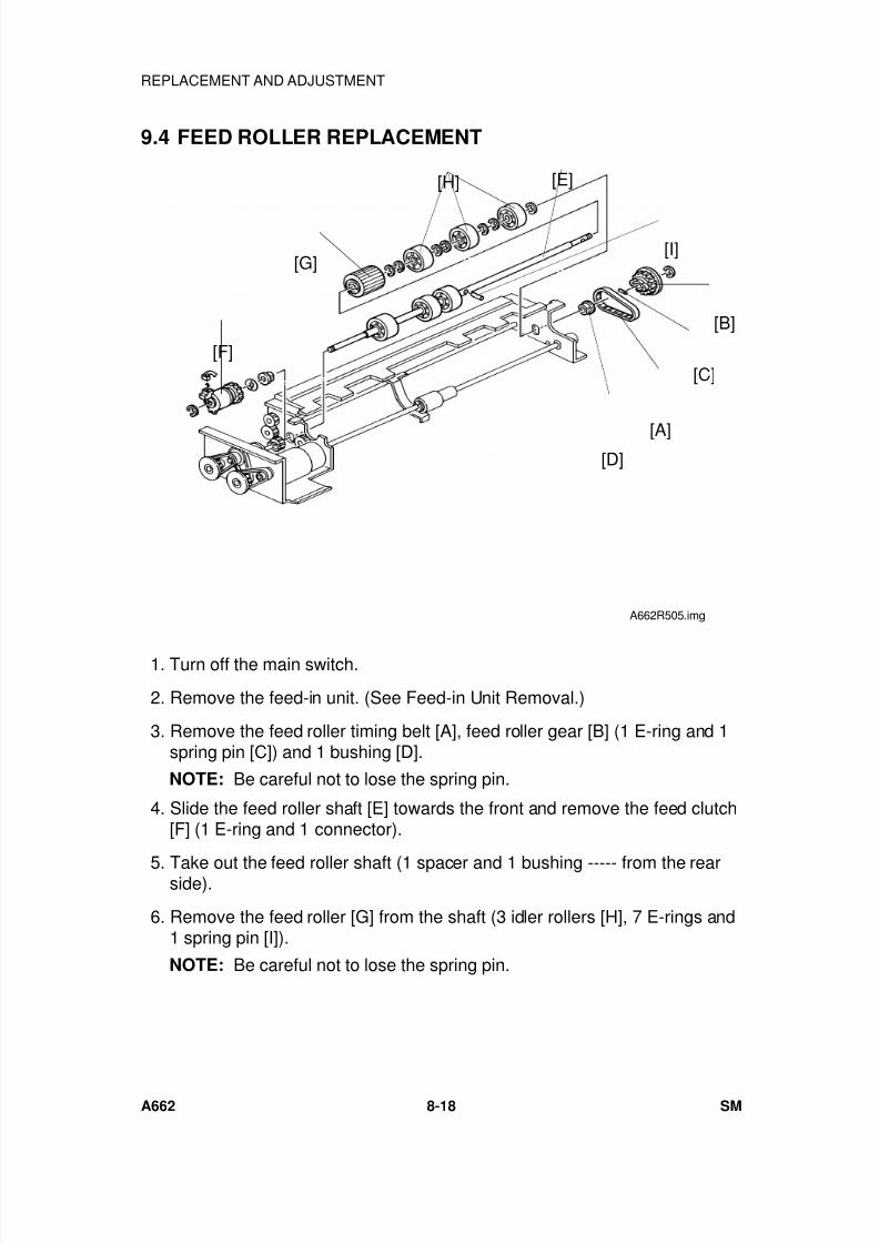
7/18/2019 A219 245 B019 4015 3813 Service
http://slidepdf.com/reader/full/a219-245-b019-4015-3813-service 279/372
9.4 FEED ROLLER REPLACEMENT
1. Turn off the main switch.
2. Remove the feed-in unit. (See Feed-in Unit Removal.)
3. Remove the feed roller timing belt [A], feed roller gear [B] (1 E-ring and 1spring pin [C]) and 1 bushing [D].
NOTE: Be careful not to lose the spring pin.
4. Slide the feed roller shaft [E] towards the front and remove the feed clutch[F] (1 E-ring and 1 connector).
5. Take out the feed roller shaft (1 spacer and 1 bushing ----- from the rearside).
6. Remove the feed roller [G] from the shaft (3 idler rollers [H], 7 E-rings and1 spring pin [I]).
NOTE: Be careful not to lose the spring pin.
[H] [E]
[G]
[F]
[D][A]
[C]
[B]
[I]
A662R505.img
REPLACEMENT AND ADJUSTMENT
A662 8-18 SM
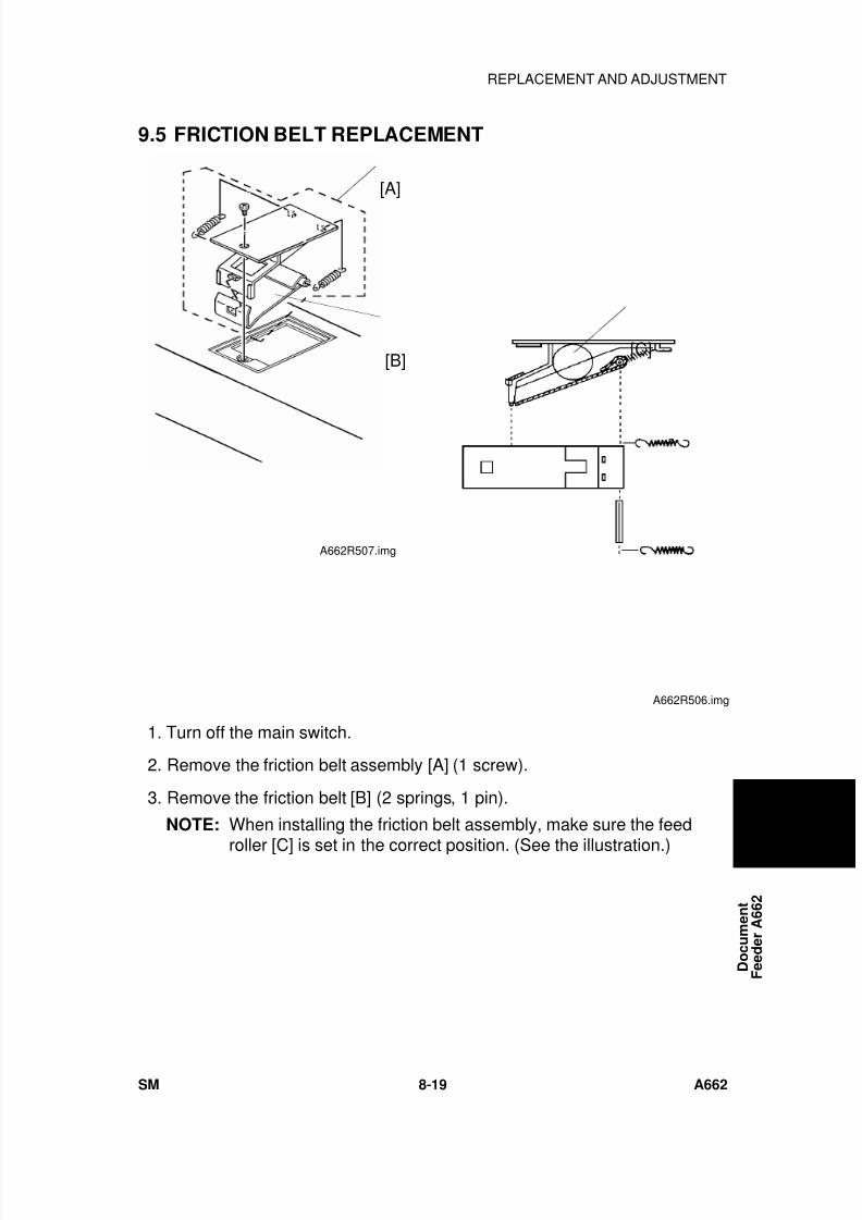
7/18/2019 A219 245 B019 4015 3813 Service
http://slidepdf.com/reader/full/a219-245-b019-4015-3813-service 280/372
9.5 FRICTION BELT REPLACEMENT
1. Turn off the main switch.
2. Remove the friction belt assembly [A] (1 screw).
3. Remove the friction belt [B] (2 springs, 1 pin).
NOTE: When installing the friction belt assembly, make sure the feed
roller [C] is set in the correct position. (See the illustration.)
[C]
A662R506.img
[A]
[B]
A662R507.img
D o c u m e n t
F e e d e r A 6 6 2
REPLACEMENT AND ADJUSTMENT
SM 8-19 A662
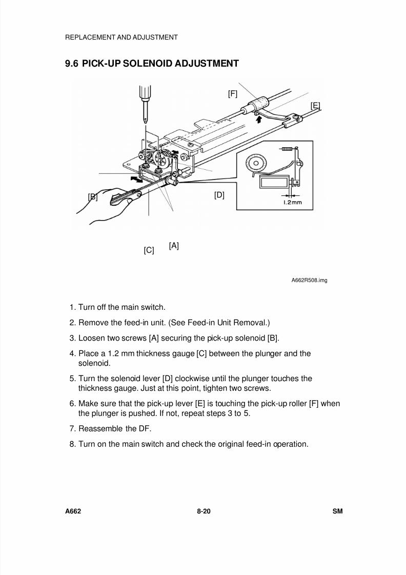
7/18/2019 A219 245 B019 4015 3813 Service
http://slidepdf.com/reader/full/a219-245-b019-4015-3813-service 281/372
9.6 PICK-UP SOLENOID ADJUSTMENT
1. Turn off the main switch.
2. Remove the feed-in unit. (See Feed-in Unit Removal.)
3. Loosen two screws [A] securing the pick-up solenoid [B].
4. Place a 1.2 mm thickness gauge [C] between the plunger and thesolenoid.
5. Turn the solenoid lever [D] clockwise until the plunger touches thethickness gauge. Just at this point, tighten two screws.
6. Make sure that the pick-up lever [E] is touching the pick-up roller [F] whenthe plunger is pushed. If not, repeat steps 3 to 5.
7. Reassemble the DF.
8. Turn on the main switch and check the original feed-in operation.
[F]
[E]
[A][C]
[B][D]
A662R508.img
REPLACEMENT AND ADJUSTMENT
A662 8-20 SM

7/18/2019 A219 245 B019 4015 3813 Service
http://slidepdf.com/reader/full/a219-245-b019-4015-3813-service 282/372
SORTER
A657

7/18/2019 A219 245 B019 4015 3813 Service
http://slidepdf.com/reader/full/a219-245-b019-4015-3813-service 283/372
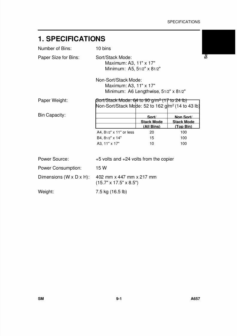
7/18/2019 A219 245 B019 4015 3813 Service
http://slidepdf.com/reader/full/a219-245-b019-4015-3813-service 284/372
1. SPECIFICATIONS
Number of Bins: 10 bins
Paper Size for Bins: Sort/Stack Mode:Maximum: A3, 11" x 17"Minimum: A5, 51/2" x 81/2"
Non-Sort/Stack Mode:Maximum: A3, 11" x 17"Minimum: A6 Lengthwise, 51/2" x 81/2"
Paper Weight: Sort/Stack Mode: 64 to 90 g/m2 (17 to 24 lb)Non-Sort/Stack Mode: 52 to 162 g/m2 (14 to 43 lb)
Bin Capacity:
Power Source: +5 volts and +24 volts from the copier
Power Consumption: 15 W
Dimensions (W x D x H): 402 mm x 447 mm x 217 mm(15.7" x 17.5" x 8.5")
Weight: 7.5 kg (16.5 lb)
Sort/Stack Mode
(All Bins)
Non Sort/Stack Mode
(Top Bin)
A4, 81/2" x 11" or less 20 100B4, 81/2" x 14" 15 100A3, 11" x 17" 10 100
S
o r t e r A 6 5 7
SPECIFICATIONS
SM 9-1 A657
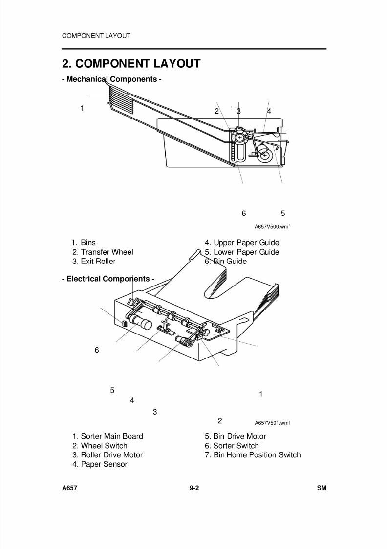
7/18/2019 A219 245 B019 4015 3813 Service
http://slidepdf.com/reader/full/a219-245-b019-4015-3813-service 285/372
2. COMPONENT LAYOUT
- Mechanical Components -
- Electrical Components -
32 41
6 5
A657V500.wmf
1. Bins 2. Transfer Wheel
3. Exit Roller
4. Upper Paper Guide 5. Lower Paper Guide
6. Bin Guide
1
23
45
6
7
A657V501.wmf
1. Sorter Main Board 2. Wheel Switch 3. Roller Drive Motor 4. Paper Sensor
5. Bin Drive Motor 6. Sorter Switch 7. Bin Home Position Switch
COMPONENT LAYOUT
A657 9-2 SM
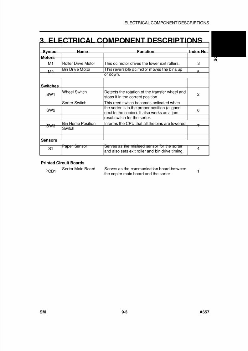
7/18/2019 A219 245 B019 4015 3813 Service
http://slidepdf.com/reader/full/a219-245-b019-4015-3813-service 286/372
3. ELECTRICAL COMPONENT DESCRIPTIONS
Symbol Name Function Index No.
Motors
M1 Roller Drive Motor This dc motor drives the lower exit rollers. 3
M2Bin Drive Motor This reversible dc motor moves the bins up
or down.5
Switches
SW1Wheel Switch Detects the rotation of the transfer wheel and
stops it in the correct position.2
SW2
Sorter Switch This reed switch becomes activated whenthe sorter is in the proper position (alignednext to the copier). It also works as a jamreset switch for the sorter.
6
SW3 Bin Home PositionSwitch
Informs the CPU that all the bins are lowered. 7
Sensors
S1 Paper Sensor Serves as the misfeed sensor for the sorterand also sets exit roller and bin drive timing.
4
Printed Circuit Boards
PCB1Sorter Main Board Serves as the communication board between
the copier main board and the sorter.1
S
o r t e r A 6 5 7
ELECTRICAL COMPONENT DESCRIPTIONS
SM 9-3 A657
7/18/2019 A219 245 B019 4015 3813 Service
http://slidepdf.com/reader/full/a219-245-b019-4015-3813-service 287/372
4. BASIC OPERATION
- Clear Mode (PROOF MODE) -
When the main switch of the copier is turned on, the sorter automaticallyassumes clear mode. In this mode, all copies are stacked in the first bin. Thesorter also assumes clear mode when interrupt mode is selected.
Sorter operation begins when the copier sends the paper feed signal to theselected paper feed station. At this time, the roller drive motor energizes.When the paper exits onto the sorter bin, the paper sensor is de-activatedand the roller drive motor is then de-energized. The copier main boardmonitors the paper sensor through the sorter main board to check for papermisfeeds.
- Sort Mode -
In this mode, all copies of the first original are delivered to separate binsstarting from the top. The copies of the second original are delivered to thesame bins, but starting from the bottom. The copies of the third original startfrom the top and so on. At 400 milliseconds after the copy has gone throughthe paper sensor, the bin drive motor turns on to advance the bins one step.
- Stack Mode -
In this mode, all copies of the first original are delivered to the first bin, all
copies of the second original are delivered to the second bin, and so on. At400 milliseconds after the last copy of the original has gone through thepaper sensor, the bin drive motor turns on to advance the bins one step.
BASIC OPERATION
A657 9-4 SM
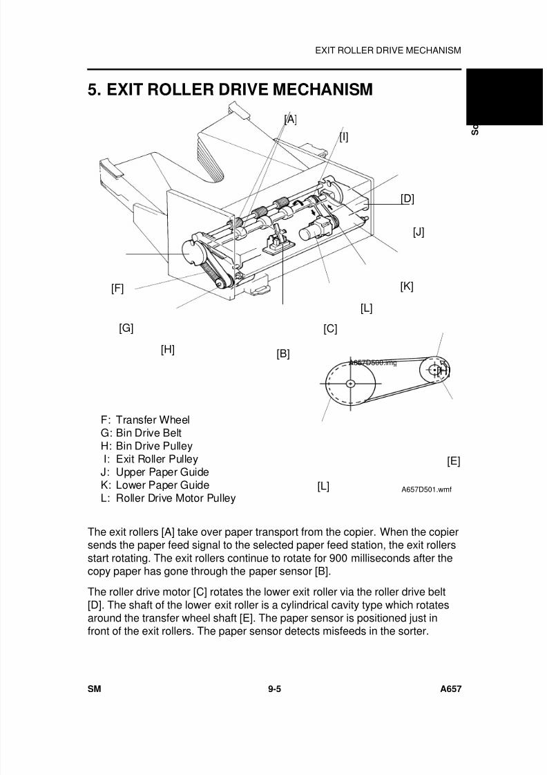
7/18/2019 A219 245 B019 4015 3813 Service
http://slidepdf.com/reader/full/a219-245-b019-4015-3813-service 288/372
5. EXIT ROLLER DRIVE MECHANISM
F: Transfer WheelG: Bin Drive BeltH: Bin Drive Pulley I: Exit Roller PulleyJ: Upper Paper GuideK: Lower Paper GuideL: Roller Drive Motor Pulley
The exit rollers [A] take over paper transport from the copier. When the copiersends the paper feed signal to the selected paper feed station, the exit rollersstart rotating. The exit rollers continue to rotate for 900 milliseconds after thecopy paper has gone through the paper sensor [B].
The roller drive motor [C] rotates the lower exit roller via the roller drive belt[D]. The shaft of the lower exit roller is a cylindrical cavity type which rotatesaround the transfer wheel shaft [E]. The paper sensor is positioned just infront of the exit rollers. The paper sensor detects misfeeds in the sorter.
[A]
[I]
[D]
[J]
[K]
[L]
[C]
[B]
[F]
[G]
[H]A657D500.img
[H]
[E]
[L] A657D501.wmf
S
o r t e r A 6 5 7
EXIT ROLLER DRIVE MECHANISM
SM 9-5 A657
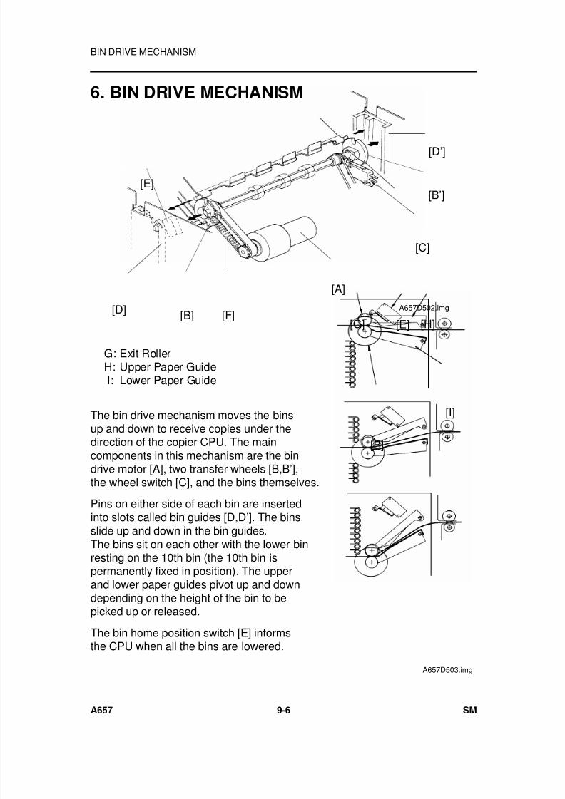
7/18/2019 A219 245 B019 4015 3813 Service
http://slidepdf.com/reader/full/a219-245-b019-4015-3813-service 289/372
6. BIN DRIVE MECHANISM
G: Exit RollerH: Upper Paper Guide I: Lower Paper Guide
The bin drive mechanism moves the binsup and down to receive copies under thedirection of the copier CPU. The maincomponents in this mechanism are the bindrive motor [A], two transfer wheels [B,B’],the wheel switch [C], and the bins themselves.
Pins on either side of each bin are insertedinto slots called bin guides [D,D’]. The binsslide up and down in the bin guides.The bins sit on each other with the lower bin
resting on the 10th bin (the 10th bin ispermanently fixed in position). The upperand lower paper guides pivot up and downdepending on the height of the bin to bepicked up or released.
The bin home position switch [E] informsthe CPU when all the bins are lowered.
[B’]
[D’]
[A]
[E]
[D] [B] [F]
[C]
A657D502.img
[G] [E] [H]
[I]
[B]
A657D503.img
BIN DRIVE MECHANISM
A657 9-6 SM
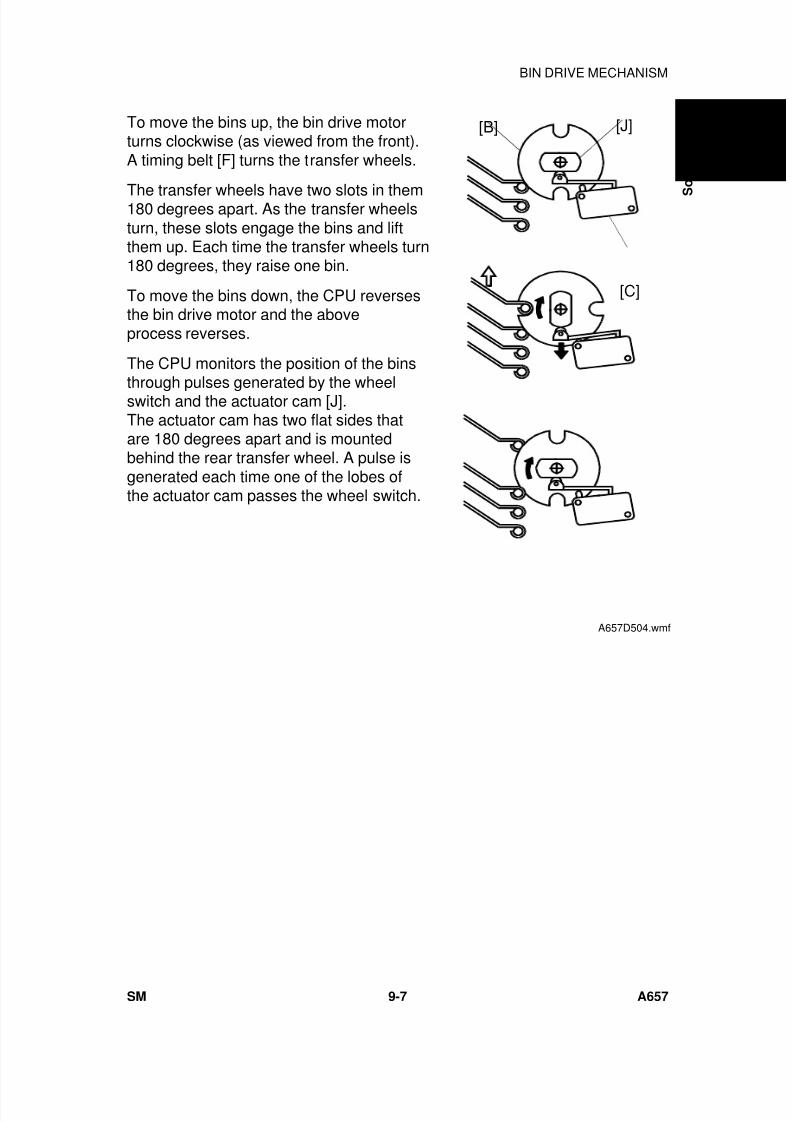
7/18/2019 A219 245 B019 4015 3813 Service
http://slidepdf.com/reader/full/a219-245-b019-4015-3813-service 290/372
To move the bins up, the bin drive motorturns clockwise (as viewed from the front).A timing belt [F] turns the transfer wheels.
The transfer wheels have two slots in them180 degrees apart. As the transfer wheelsturn, these slots engage the bins and liftthem up. Each time the transfer wheels turn180 degrees, they raise one bin.
To move the bins down, the CPU reversesthe bin drive motor and the aboveprocess reverses.
The CPU monitors the position of the bins
through pulses generated by the wheelswitch and the actuator cam [J].The actuator cam has two flat sides thatare 180 degrees apart and is mountedbehind the rear transfer wheel. A pulse isgenerated each time one of the lobes ofthe actuator cam passes the wheel switch.
[J][B]
[C]
A657D504.wmf
S
o r t e r A 6 5 7
BIN DRIVE MECHANISM
SM 9-7 A657
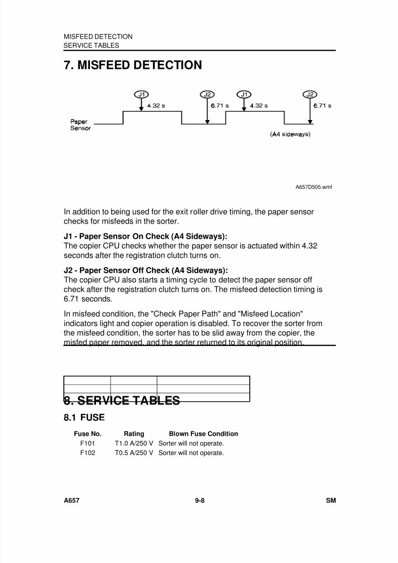
7/18/2019 A219 245 B019 4015 3813 Service
http://slidepdf.com/reader/full/a219-245-b019-4015-3813-service 291/372
7. MISFEED DETECTION
In addition to being used for the exit roller drive timing, the paper sensorchecks for misfeeds in the sorter.
J1 - Paper Sensor On Check (A4 Sideways):The copier CPU checks whether the paper sensor is actuated within 4.32seconds after the registration clutch turns on.
J2 - Paper Sensor Off Check (A4 Sideways):The copier CPU also starts a timing cycle to detect the paper sensor off
check after the registration clutch turns on. The misfeed detection timing is6.71 seconds.
In misfeed condition, the "Check Paper Path" and "Misfeed Location"indicators light and copier operation is disabled. To recover the sorter fromthe misfeed condition, the sorter has to be slid away from the copier, themisfed paper removed, and the sorter returned to its original position.
8. SERVICE TABLES
8.1 FUSE
Fuse No. Rating Blown Fuse Condition
F101 T1.0 A/250 V Sorter will not operate.F102 T0.5 A/250 V Sorter will not operate.
SERVICE TABLES
A657D505.wmf
MISFEED DETECTION
A657 9-8 SM
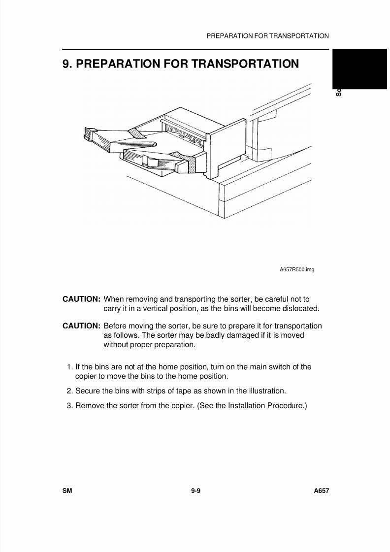
7/18/2019 A219 245 B019 4015 3813 Service
http://slidepdf.com/reader/full/a219-245-b019-4015-3813-service 292/372
9. PREPARATION FOR TRANSPORTATION
CAUTION: When removing and transporting the sorter, be careful not tocarry it in a vertical position, as the bins will become dislocated.
CAUTION: Before moving the sorter, be sure to prepare it for transportationas follows. The sorter may be badly damaged if it is movedwithout proper preparation.
1. If the bins are not at the home position, turn on the main switch of thecopier to move the bins to the home position.
2. Secure the bins with strips of tape as shown in the illustration.
3. Remove the sorter from the copier. (See the Installation Procedure.)
A657R500.img
S
o r t e r A 6 5 7
PREPARATION FOR TRANSPORTATION
SM 9-9 A657
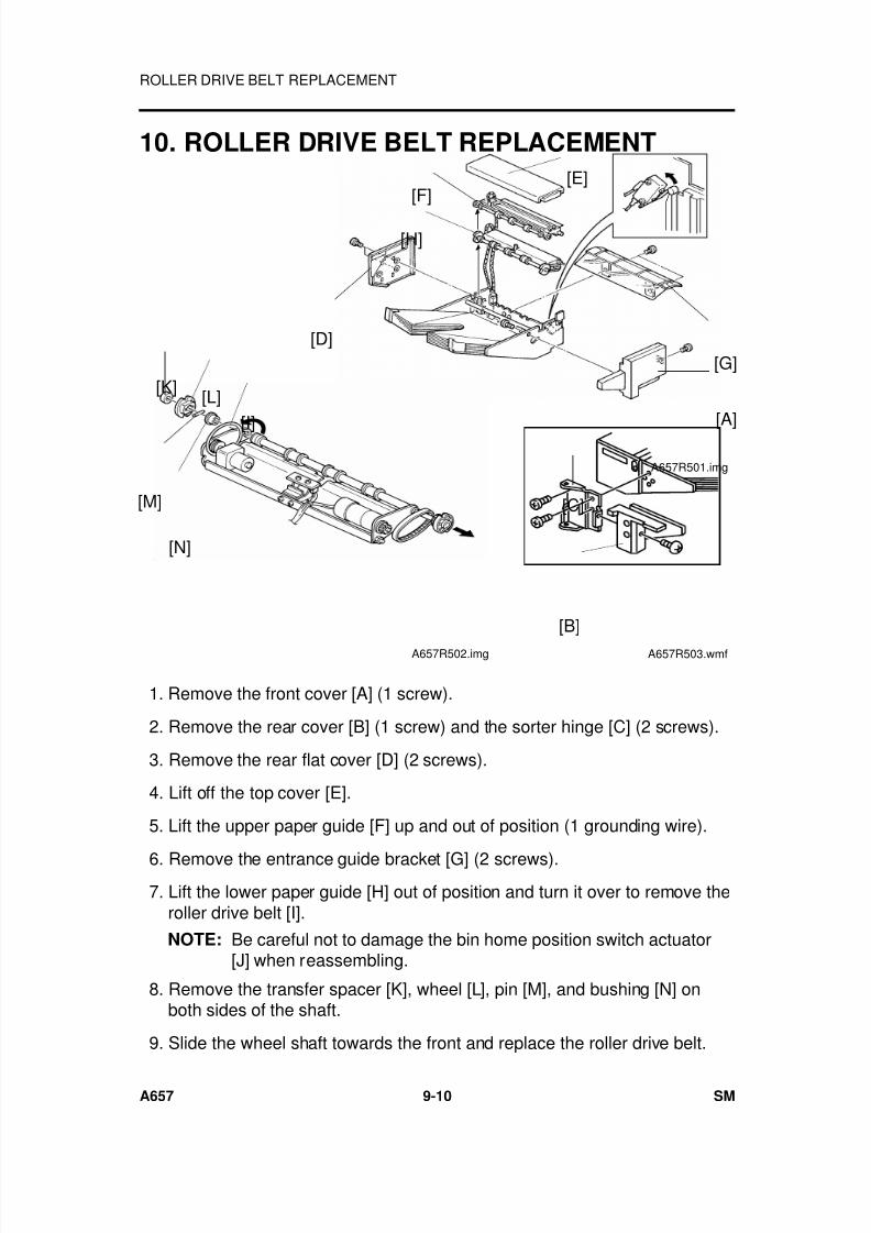
7/18/2019 A219 245 B019 4015 3813 Service
http://slidepdf.com/reader/full/a219-245-b019-4015-3813-service 293/372
10. ROLLER DRIVE BELT REPLACEMENT
1. Remove the front cover [A] (1 screw).
2. Remove the rear cover [B] (1 screw) and the sorter hinge [C] (2 screws).
3. Remove the rear flat cover [D] (2 screws).
4. Lift off the top cover [E].
5. Lift the upper paper guide [F] up and out of position (1 grounding wire).
6. Remove the entrance guide bracket [G] (2 screws). 7. Lift the lower paper guide [H] out of position and turn it over to remove the
roller drive belt [I].
NOTE: Be careful not to damage the bin home position switch actuator[J] when reassembling.
8. Remove the transfer spacer [K], wheel [L], pin [M], and bushing [N] onboth sides of the shaft.
9. Slide the wheel shaft towards the front and replace the roller drive belt.
[A]
[G]
[E][F]
[H]
[D]
A657R501.img
[I]
[K] [L]
[M]
[N]
A657R502.img
[C]
[B]
A657R503.wmf
ROLLER DRIVE BELT REPLACEMENT
A657 9-10 SM
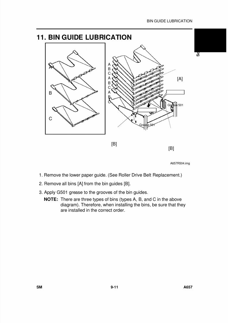
7/18/2019 A219 245 B019 4015 3813 Service
http://slidepdf.com/reader/full/a219-245-b019-4015-3813-service 294/372
11. BIN GUIDE LUBRICATION
1. Remove the lower paper guide. (See Roller Drive Belt Replacement.)
2. Remove all bins [A] from the bin guides [B].
3. Apply G501 grease to the grooves of the bin guides.
NOTE: There are three types of bins (types A, B, and C in the abovediagram). Therefore, when installing the bins, be sure that theyare installed in the correct order.
A
B
C
Grease 501
Grease 501
C
ABC
CBA
A
[B][B]
[A]
B
A657R504.img
S
o r t e r A 6 5 7
BIN GUIDE LUBRICATION
SM 9-11 A657

7/18/2019 A219 245 B019 4015 3813 Service
http://slidepdf.com/reader/full/a219-245-b019-4015-3813-service 295/372

7/18/2019 A219 245 B019 4015 3813 Service
http://slidepdf.com/reader/full/a219-245-b019-4015-3813-service 296/372
APPENDIX
ELECRICAL COMPONENT
LAYOUT&
TIMING CHART

7/18/2019 A219 245 B019 4015 3813 Service
http://slidepdf.com/reader/full/a219-245-b019-4015-3813-service 297/372
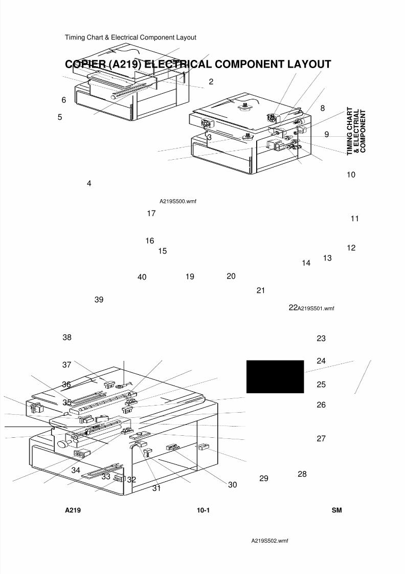
7/18/2019 A219 245 B019 4015 3813 Service
http://slidepdf.com/reader/full/a219-245-b019-4015-3813-service 298/372
COPIER (A219) ELECTRICAL COMPONENT LAYOUT
4
2
3
1
5
6
A219S500.wmf
10
15
1413
12
11
9
8718
17
16
A219S501.wmf
24
40
23
28
27
26
25
19 20
21
22
29
39
313233
34
35
36
38
37
30
A219S502.wmf
T I M I N G
C H A R T
& E L E C T R I A L
C O M P O N E N T
Timing Chart & Electrical Component Layout
A219 10-1 SM
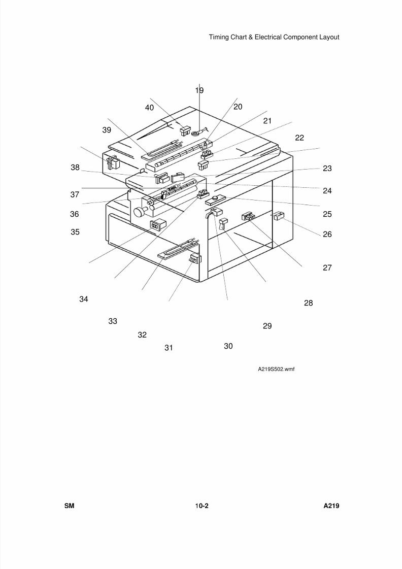
7/18/2019 A219 245 B019 4015 3813 Service
http://slidepdf.com/reader/full/a219-245-b019-4015-3813-service 299/372
24
40
23
28
27
26
25
19
20
21
22
29
39
31
32
33
34
35
36
38
37
30
A219S502.wmf
Timing Chart & Electrical Component Layout
SM 10-2 A219
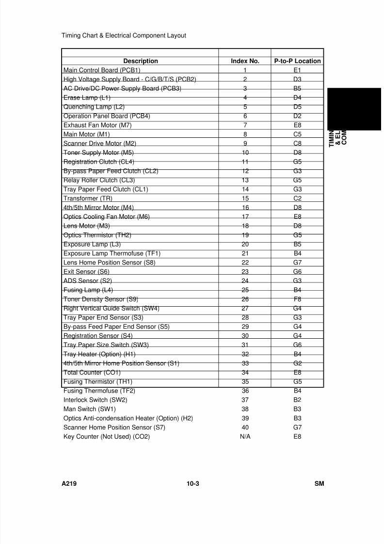
7/18/2019 A219 245 B019 4015 3813 Service
http://slidepdf.com/reader/full/a219-245-b019-4015-3813-service 300/372
Description Index No. P-to-P Location
Main Control Board (PCB1) 1 E1High Voltage Supply Board - C/G/B/T/S (PCB2) 2 D3AC Drive/DC Power Supply Board (PCB3) 3 B5
Erase Lamp (L1) 4 D4Quenching Lamp (L2) 5 D5Operation Panel Board (PCB4) 6 D2Exhaust Fan Motor (M7) 7 E8Main Motor (M1) 8 C5Scanner Drive Motor (M2) 9 C8Toner Supply Motor (M5) 10 D8Registration Clutch (CL4) 11 G5By-pass Paper Feed Clutch (CL2) 12 G3Relay Roller Clutch (CL3) 13 G5
Tray Paper Feed Clutch (CL1) 14 G3Transformer (TR) 15 C24th/5th Mirror Motor (M4) 16 D8Optics Cooling Fan Motor (M6) 17 E8Lens Motor (M3) 18 D8Optics Thermistor (TH2) 19 G5Exposure Lamp (L3) 20 B5Exposure Lamp Thermofuse (TF1) 21 B4Lens Home Position Sensor (S8) 22 G7Exit Sensor (S6) 23 G6
ADS Sensor (S2) 24 G3Fusing Lamp (L4) 25 B4Toner Density Sensor (S9) 26 F8Right Vertical Guide Switch (SW4) 27 G4Tray Paper End Sensor (S3) 28 G3By-pass Feed Paper End Sensor (S5) 29 G4Registration Sensor (S4) 30 G4Tray Paper Size Switch (SW3) 31 G6Tray Heater (Option) (H1) 32 B44th/5th Mirror Home Position Sensor (S1) 33 G2Total Counter (CO1) 34 E8
Fusing Thermistor (TH1) 35 G5Fusing Thermofuse (TF2) 36 B4Interlock Switch (SW2) 37 B2Man Switch (SW1) 38 B3Optics Anti-condensation Heater (Option) (H2) 39 B3Scanner Home Position Sensor (S7) 40 G7Key Counter (Not Used) (CO2) N/A E8
T I M I N G
C H A R T
& E L E C T R I A L
C O M P O N E N T
Timing Chart & Electrical Component Layout
A219 10-3 SM
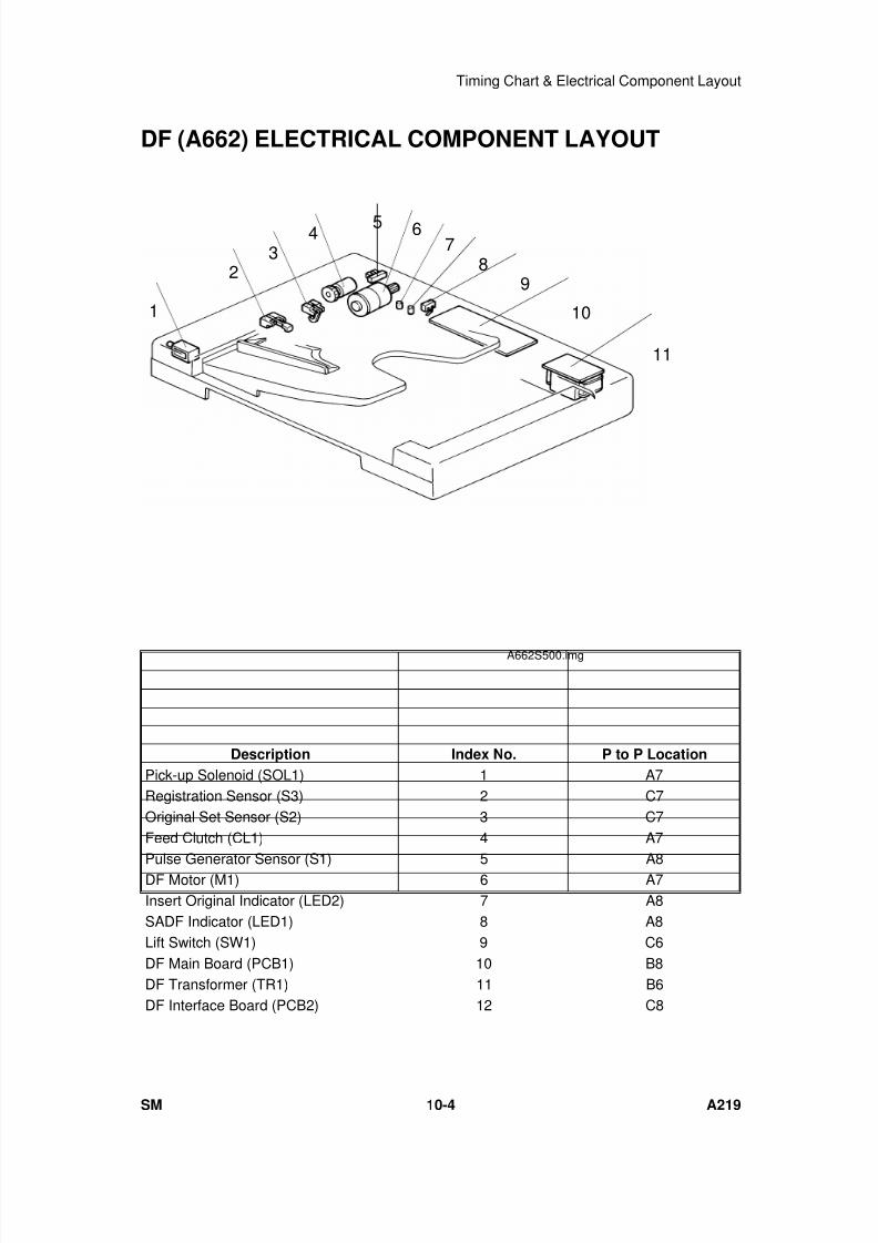
7/18/2019 A219 245 B019 4015 3813 Service
http://slidepdf.com/reader/full/a219-245-b019-4015-3813-service 301/372
DF (A662) ELECTRICAL COMPONENT LAYOUT
Description Index No. P to P Location
Pick-up Solenoid (SOL1) 1 A7Registration Sensor (S3) 2 C7Original Set Sensor (S2) 3 C7Feed Clutch (CL1) 4 A7
Pulse Generator Sensor (S1) 5 A8DF Motor (M1) 6 A7Insert Original Indicator (LED2) 7 A8SADF Indicator (LED1) 8 A8Lift Switch (SW1) 9 C6DF Main Board (PCB1) 10 B8DF Transformer (TR1) 11 B6DF Interface Board (PCB2) 12 C8
1
98
7654
32
10
11
A662S500.img
Timing Chart & Electrical Component Layout
SM 10-4 A219
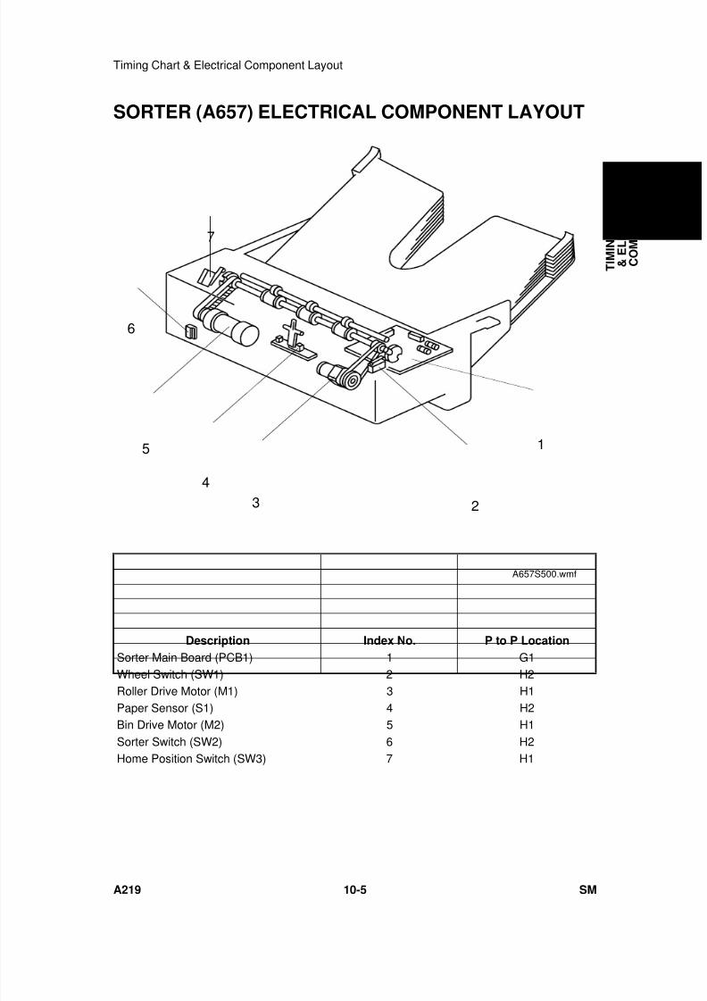
7/18/2019 A219 245 B019 4015 3813 Service
http://slidepdf.com/reader/full/a219-245-b019-4015-3813-service 302/372
SORTER (A657) ELECTRICAL COMPONENT LAYOUT
Description Index No. P to P Location
Sorter Main Board (PCB1) 1 G1Wheel Switch (SW1) 2 H2
Roller Drive Motor (M1) 3 H1Paper Sensor (S1) 4 H2Bin Drive Motor (M2) 5 H1Sorter Switch (SW2) 6 H2Home Position Switch (SW3) 7 H1
1
2
5
43
6
7
A657S500.wmf
T I M I N G
C H A R T
& E L E C T R I A L
C O M P O N E N T
Timing Chart & Electrical Component Layout
A219 10-5 SM
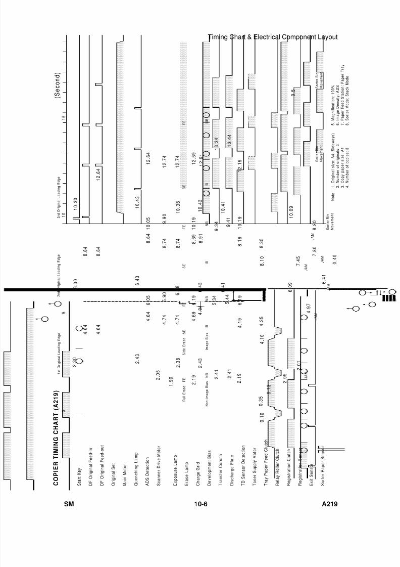
7/18/2019 A219 245 B019 4015 3813 Service
http://slidepdf.com/reader/full/a219-245-b019-4015-3813-service 303/372
F E
S E
F E
S E
F E
S i d e E r a s e
S E
N B
I B
N B
I B
N B
I m a g e B i a s
I B
N o n - i m a
g e B i a s
N B
C O P I E R
T I M I N G C
H A R T
( A 2 1 9
)
S t a r t K e y
D F O r i g i n a l F e e d - i n
D F O r i g i n a l F e e d - o u t
O r i g i n a l S e t
M a i n M o t o r
Q u e n c h i n g L a m p
A D S
D e t e c t i o n
S c a n n e r D r i v e M o t o r
E x p o s u r e L a m p
E r a s e L a m p
C h a r g e G r i d
D e v e l o p m e n t B i a s
T r a n s f e r C o r o n a
D i s c h a r g e P l a t e
T D
S e n s o r D e t e c t i o n
T o n e r S u p p l y M o t o r
T r a y P a p e r F e e d C l u t c h
R e l a y R o l l e r C l u t c h
R e g i s t r a t i o n C l u t c h
R e g i s t r a t i o n S e n s o r
E x i t S e n s o r
S o r t e r P a p e r S e n s o r
N o
t e :
1 . O r i g i n a l s i z e : A 4 ( S i d e w a y s )
2 . N u m b e r o f o r i g i n a l s : 3
3 . C o p y p a p e r s i z e : A 4
4 . N u m b e r o f c o p i e s : 3
( S e c o n d )
2 . 4 3
5 . 3 4
4 . 6 4
8 . 9 1
4 . 9 1
1 0 . 4 1
1 3 . 3 4
1 2 . 9 1
4 . 6 4
4 . 6 4
8 . 6 4
8 . 6 4
1 2 . 6 4
2 . 3 0
6 . 3 0
1 0 . 3 0
2 . 4 3
6 . 4 3
1 0 . 4 3
2 . 0 5
6 . 0 5
1 0 . 0 5
8 . 6 4
1 2 . 6 4
0
5
1 0
1 5
1 . 9 0
4 . 7 4
5 . 9 0
8 . 7 4
9 . 9 0
1 2 . 7 4
2 . 1 9
4 . 6 9
6 . 1 9
8 . 6 9
1 0 . 1 9
1 2 . 6 9
2 . 4 1
2 . 4 1
5 . 4 4
2 . 1 9
6 . 4 1
4 . 1 9
9 . 3 4
9 . 4 1
1 3 . 4 4
0 . 1 0
0 . 3 5
4 . 1 0
4 . 3 5
8 . 1 0
8 . 3 5
2 . 0 9
6 . 0 9
1 0 . 0 9
F u l l E
r a s e
F E
6 . 4 3
1 0 . 4 3
2 . 3 8
4 . 7 4
6 . 3 8
8 . 7 4
1 0 . 3 8
1 2 . 7 4
J A M
2 . 0 1
4 . 9 7
J A M 7
. 4 5
J A M
J A M
7 . 8 0
J A M
6 . 4 1
0 . 4 0
S o r t e r B i n
M o v e m e n t
8 . 8 0
J A M
S o r t e r B i n
M o v e m e n t
S o r t e r B i n
M o v e m e n t
1 s t O r i g i n a l L e a d i n g E d g e
2 n d O r i g i n a l L e a d i n g E d g e
3 r d O r i g i n a l L e a d i n g E d g e
6 . 1 9
8 . 1 9
1 0 . 1 9
1 2 . 1 9
0
. 1 3
0 . 5
5 . M a g n i f i c a t i o n
: 1 0 0 %
6 . I m a g e D e n s i t
y : A D S
7 . P a p e r F e e d S
t a t i o n : P a p e r T r a y
8 . S o r t e r M o d e :
S t a c k M o d e
Timing Chart & Electrical Component Layout
SM 10-6 A219
7/18/2019 A219 245 B019 4015 3813 Service
http://slidepdf.com/reader/full/a219-245-b019-4015-3813-service 304/372
A245SERVICE MANUAL
-Insert Version-
The A245 copier is based on the A219 copier.
Only the differences from the A219 copier are described in thefollowing pages. Refer to the A219 copier service manualregarding the other information.

7/18/2019 A219 245 B019 4015 3813 Service
http://slidepdf.com/reader/full/a219-245-b019-4015-3813-service 305/372
7/18/2019 A219 245 B019 4015 3813 Service
http://slidepdf.com/reader/full/a219-245-b019-4015-3813-service 306/372
A245
Service Manual

7/18/2019 A219 245 B019 4015 3813 Service
http://slidepdf.com/reader/full/a219-245-b019-4015-3813-service 307/372

7/18/2019 A219 245 B019 4015 3813 Service
http://slidepdf.com/reader/full/a219-245-b019-4015-3813-service 308/372
1. SPECIFICATIONS
NOTE: Only items marked with are different from the A219 copier.
Configuration: Desktop
Copy Process: Dry electrostatic transfer system
Originals: Sheet/Book
Original Size: Maximum: A3/11" x 17"
Copy Paper Size: Maximum: A3/11" x 17"Minimum:
A5/51/2" x 81/2" sideways (Paper tray feed)
A6/51/2" x 81/2" lengthwise (By-pass feed)Non-standard sizes:Vertical 45 mm ~ 308 mm, 1.8" ~ 12"Horizontal 148 mm ~ 432 mm, 5.8" ~ 17"
Copy Paper Weight: Paper tray feed: 64 to 90 g/m2, 17 to 24 lbBy-pass feed: 52 to 157 g/m2, 14 to 42 lb
Reproduction Ratios:
Zoom: From 50% to 200% in 1% steps
Copying Speed: 18 copies/minute (A4/8.5" x 11" sideways)10 copies/minute (A3/11" x 17")
Warm-up Time: 120 V machines: Less than 35 seconds (at 23°C)230 V machines: Less than 45 seconds (at 23°C)
First Copy Time: Less than 6.5 seconds (A4/8.5" x 11" sideways)
Copy Number Input: Number keys, 1 to 99
Manual Image DensitySelection:
7 steps
Metric Version Inch Version
Enlargement200%141%
122%
200%155%
129%Full Size 100% 100%
Reduction
93% 82% 71% 50%
93% 74% 65% 50%
A 2 4 5
C O P I E R
SPECIFICATIONS
SM 11-1 A245
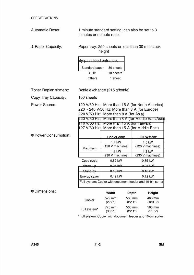
7/18/2019 A219 245 B019 4015 3813 Service
http://slidepdf.com/reader/full/a219-245-b019-4015-3813-service 309/372
Automatic Reset: 1 minute standard setting; can also be set to 3minutes or no auto reset
Paper Capacity: Paper tray: 250 sheets or less than 30 mm stackheight
By-pass feed entrance:
Toner Replenishment: Bottle exchange (215 g/bottle)
Copy Tray Capacity: 100 sheets
Power Source: 120 V/60 Hz: More than 15 A (for North America)220 ~ 240 V/50 Hz: More than 8 A (for Europe)220 V/50 Hz: More than 8 A (for Asia)220 V/60 Hz: More than 8 A (for Middle East/Asia)110 V/60 Hz: More than 15 A (for Taiwan)127 V/60 Hz: More than 15 A (for Middle East)
Power Consumption:
Dimensions:
Copier only Full system*
Maximum1.4 kW(120 V machines) 1.5 kW(120 V machines)
1.1 kW(230 V machines)
1.2 kW(230 V machines)
Copy cycle 0.82 kW 0.85 kW
Warm-up 0.95 kW 0.95 kW
Stand-by 0.16 kW 0.16 kW
Energy saver 0.12 kW 0.12 kW
*Full system: Copier with document feeder and 10-bin sorter
Width Depth Height
Copier579 mm(22.8")
560 mm(22.1")
465 mm(183.8")
Full system*775 mm(30.2")
560 mm(22.1")
563 mm(21.5")
*Full system: Copier with document feeder and 10-bin sorter
Standard paper 80 sheets
OHP 10 sheets
Others 1 sheet
SPECIFICATIONS
A245 11-2 SM
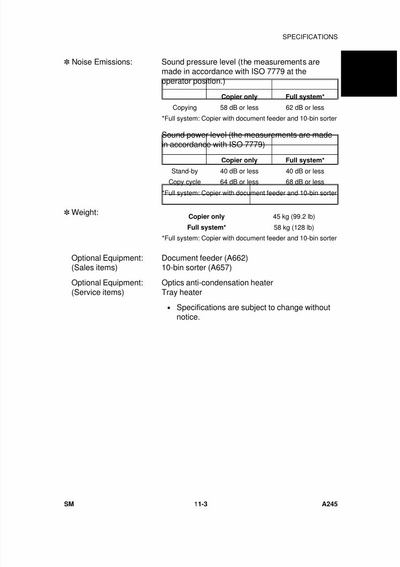
7/18/2019 A219 245 B019 4015 3813 Service
http://slidepdf.com/reader/full/a219-245-b019-4015-3813-service 310/372
Noise Emissions: Sound pressure level (the measurements aremade in accordance with ISO 7779 at theoperator position.)
Sound power level (the measurements are madein accordance with ISO 7779)
Weight:
Optional Equipment:(Sales items)
Document feeder (A662)10-bin sorter (A657)
Optional Equipment:
(Service items)
Optics anti-condensation heater
Tray heater• Specifications are subject to change without
notice.
Copier only Full system*Copying 58 dB or less 62 dB or less
*Full system: Copier with document feeder and 10-bin sorter
Copier only Full system*
Stand-by 40 dB or less 40 dB or less
Copy cycle 64 dB or less 68 dB or less
*Full system: Copier with document feeder and 10-bin sorter
Copier only 45 kg (99.2 lb)
Full system* 58 kg (128 lb)
*Full system: Copier with document feeder and 10-bin sorter
A 2 4 5
C O P I E R
SPECIFICATIONS
SM 11-3 A245
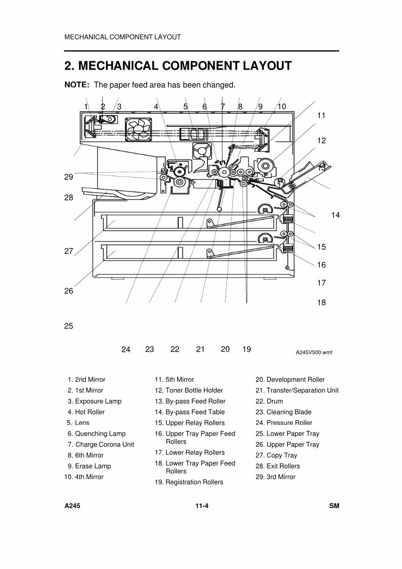
7/18/2019 A219 245 B019 4015 3813 Service
http://slidepdf.com/reader/full/a219-245-b019-4015-3813-service 311/372
2. MECHANICAL COMPONENT LAYOUT
NOTE: The paper feed area has been changed.
7 1098654321
16
15
14
13
12
11
17
18
28
29
26
27
25
2124 23 22 1920 A245V500.wmf
1. 2nd Mirror
2. 1st Mirror
3. Exposure Lamp
4. Hot Roller
5. Lens
6. Quenching Lamp
7. Charge Corona Unit
8. 6th Mirror
9. Erase Lamp
10. 4th Mirror
11. 5th Mirror
12. Toner Bottle Holder
13. By-pass Feed Roller
14. By-pass Feed Table
15. Upper Relay Rollers
16. Upper Tray Paper FeedRollers
17. Lower Relay Rollers
18. Lower Tray Paper FeedRollers
19. Registration Rollers
20. Development Roller
21. Transfer/Separation Unit
22. Drum
23. Cleaning Blade
24. Pressure Roller
25. Lower Paper Tray
26. Upper Paper Tray
27. Copy Tray
28. Exit Rollers
29. 3rd Mirror
MECHANICAL COMPONENT LAYOUT
A245 11-4 SM
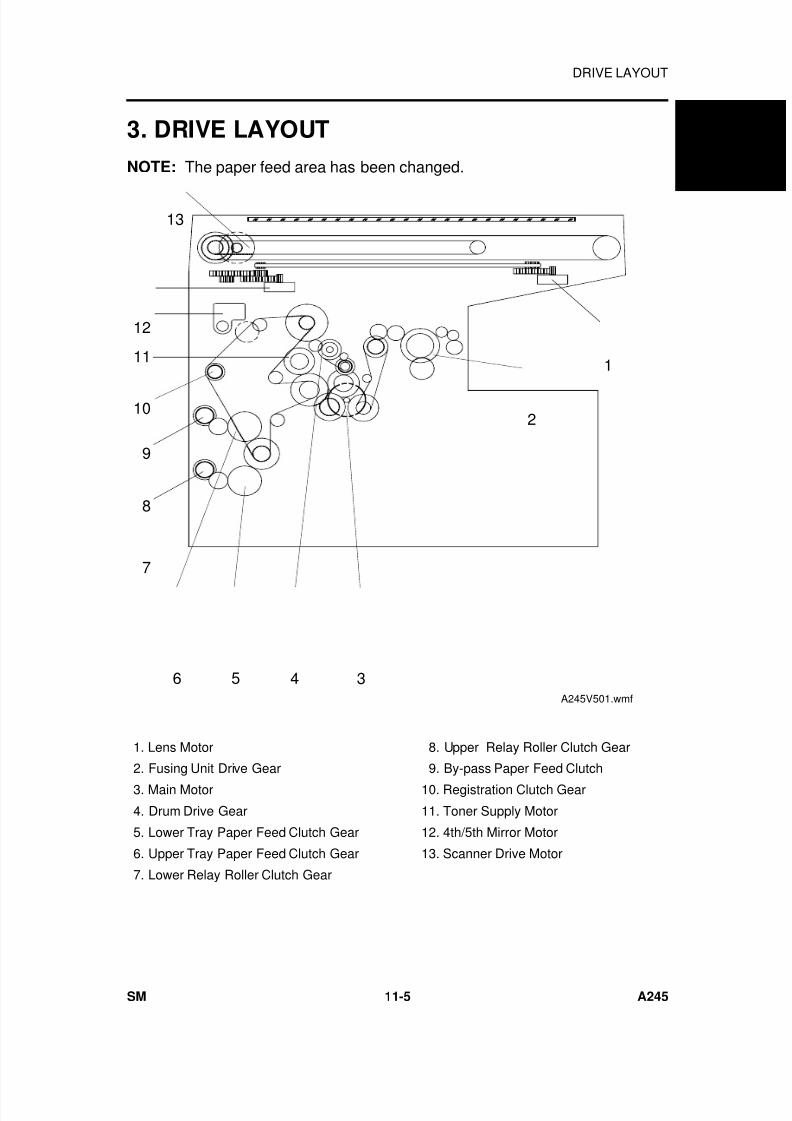
7/18/2019 A219 245 B019 4015 3813 Service
http://slidepdf.com/reader/full/a219-245-b019-4015-3813-service 312/372
3. DRIVE LAYOUT
NOTE: The paper feed area has been changed.
1
2
11
10
9
8
5 4 3
13
12
6
7
A245V501.wmf
1. Lens Motor
2. Fusing Unit Drive Gear
3. Main Motor
4. Drum Drive Gear
5. Lower Tray Paper Feed Clutch Gear
6. Upper Tray Paper Feed Clutch Gear
7. Lower Relay Roller Clutch Gear
8. Upper Relay Roller Clutch Gear
9. By-pass Paper Feed Clutch
10. Registration Clutch Gear
11. Toner Supply Motor
12. 4th/5th Mirror Motor
13. Scanner Drive Motor
A 2 4 5
C O P I E R
DRIVE LAYOUT
SM 11-5 A245
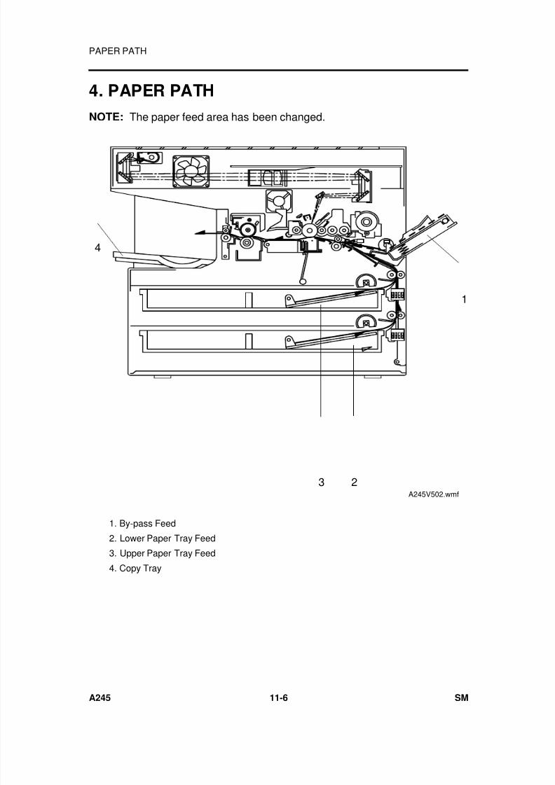
7/18/2019 A219 245 B019 4015 3813 Service
http://slidepdf.com/reader/full/a219-245-b019-4015-3813-service 313/372
4. PAPER PATH
NOTE: The paper feed area has been changed.
1
3
4
2A245V502.wmf
1. By-pass Feed
2. Lower Paper Tray Feed
3. Upper Paper Tray Feed
4. Copy Tray
PAPER PATH
A245 11-6 SM
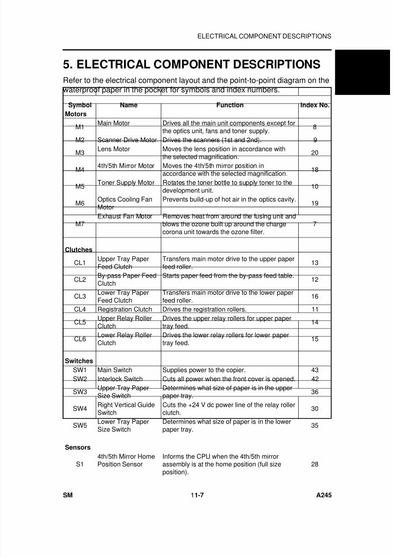
7/18/2019 A219 245 B019 4015 3813 Service
http://slidepdf.com/reader/full/a219-245-b019-4015-3813-service 314/372
5. ELECTRICAL COMPONENT DESCRIPTIONS
Refer to the electrical component layout and the point-to-point diagram on thewaterproof paper in the pocket for symbols and index numbers.
Symbol Name Function Index No.
Motors
M1Main Motor Drives all the main unit components except for
the optics unit, fans and toner supply.8
M2 Scanner Drive Motor Drives the scanners (1st and 2nd). 9
M3 Lens Motor Moves the lens position in accordance withthe selected magnification.
20
M44th/5th Mirror Motor Moves the 4th/5th mirror position in
accordance with the selected magnification.18
M5Toner Supply Motor Rotates the toner bottle to supply toner to the
development unit.
10
M6Optics Cooling FanMotor
Prevents build-up of hot air in the optics cavity.19
M7Exhaust Fan Motor Removes heat from around the fusing unit and
blows the ozone built up around the chargecorona unit towards the ozone filter.
7
Clutches
CL1Upper Tray PaperFeed Clutch
Transfers main motor drive to the upper paperfeed roller.
13
CL2By-pass Paper FeedClutch
Starts paper feed from the by-pass feed table.12
CL3 Lower Tray PaperFeed Clutch
Transfers main motor drive to the lower paperfeed roller.
16
CL4 Registration Clutch Drives the registration rollers. 11
CL5Upper Relay RollerClutch
Drives the upper relay rollers for upper papertray feed.
14
CL6Lower Relay RollerClutch
Drives the lower relay rollers for lower papertray feed.
15
Switches
SW1 Main Switch Supplies power to the copier. 43SW2 Interlock Switch Cuts all power when the front cover is opened. 42
SW3 Upper Tray PaperSize Switch
Determines what size of paper is in the upperpaper tray.
36
SW4 Right Vertical GuideSwitch
Cuts the +24 V dc power line of the relay rollerclutch.
30
SW5Lower Tray PaperSize Switch
Determines what size of paper is in the lowerpaper tray.
35
Sensors
S14th/5th Mirror HomePosition Sensor
Informs the CPU when the 4th/5th mirrorassembly is at the home position (full sizeposition).
28
A 2 4 5
C O P I E R
ELECTRICAL COMPONENT DESCRIPTIONS
SM 11-7 A245
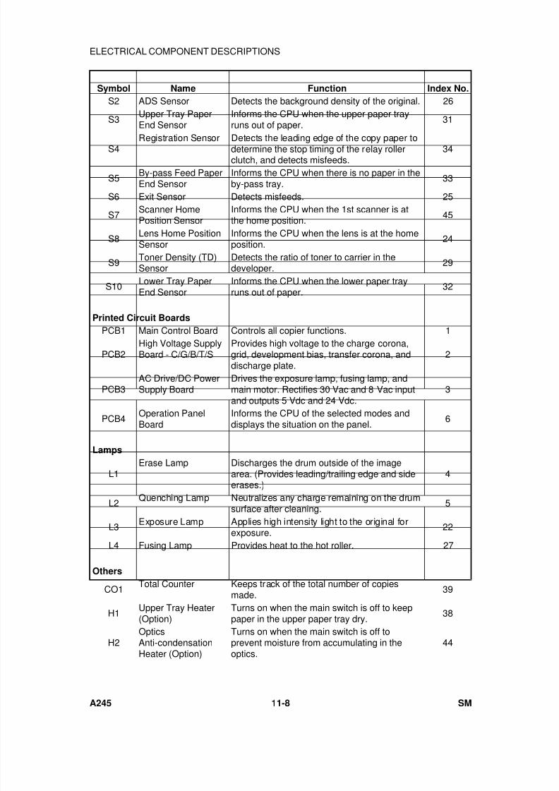
7/18/2019 A219 245 B019 4015 3813 Service
http://slidepdf.com/reader/full/a219-245-b019-4015-3813-service 315/372
Symbol Name Function Index No.
S2 ADS Sensor Detects the background density of the original. 26
S3Upper Tray PaperEnd Sensor
Informs the CPU when the upper paper trayruns out of paper.
31
S4Registration Sensor Detects the leading edge of the copy paper to
determine the stop timing of the relay rollerclutch, and detects misfeeds.
34
S5By-pass Feed PaperEnd Sensor
Informs the CPU when there is no paper in theby-pass tray.
33
S6 Exit Sensor Detects misfeeds. 25
S7Scanner HomePosition Sensor
Informs the CPU when the 1st scanner is atthe home position.
45
S8Lens Home PositionSensor
Informs the CPU when the lens is at the homeposition.
24
S9Toner Density (TD)Sensor
Detects the ratio of toner to carrier in thedeveloper.
29
S10 Lower Tray PaperEnd Sensor
Informs the CPU when the lower paper trayruns out of paper.
32
Printed Circuit Boards
PCB1 Main Control Board Controls all copier functions. 1
PCB2High Voltage SupplyBoard - C/G/B/T/S
Provides high voltage to the charge corona,grid, development bias, transfer corona, anddischarge plate.
2
PCB3AC Drive/DC PowerSupply Board
Drives the exposure lamp, fusing lamp, andmain motor. Rectifies 30 Vac and 8 Vac inputand outputs 5 Vdc and 24 Vdc.
3
PCB4 Operation PanelBoard
Informs the CPU of the selected modes anddisplays the situation on the panel.
6
Lamps
L1Erase Lamp Discharges the drum outside of the image
area. (Provides leading/trailing edge and sideerases.)
4
L2Quenching Lamp Neutralizes any charge remaining on the drum
surface after cleaning.5
L3 Exposure Lamp Applies high intensity light to the original forexposure.
22
L4 Fusing Lamp Provides heat to the hot roller. 27
Others
CO1Total Counter Keeps track of the total number of copies
made.39
H1Upper Tray Heater(Option)
Turns on when the main switch is off to keeppaper in the upper paper tray dry.
38
H2OpticsAnti-condensationHeater (Option)
Turns on when the main switch is off toprevent moisture from accumulating in theoptics.
44
ELECTRICAL COMPONENT DESCRIPTIONS
A245 11-8 SM

7/18/2019 A219 245 B019 4015 3813 Service
http://slidepdf.com/reader/full/a219-245-b019-4015-3813-service 316/372
Symbol Name Function Index No.
H3Lower Tray Heater(Option)
Turns on when the main switch is off to keeppaper in the lower paper tray dry.
37
TF1Exposure Lamp
Thermofuse
Provide back-up overheat protection around
the exposure lamp.23
TF2 Fusing Thermofuse Provide back-up overheat protection in thefusing unit.
41
TH1Fusing Thermistor Monitors the temperature around the exposure
lamp for overheat protection.40
TH2 Optics Thermistor Monitors the temperature around the exposurelamp for overheat protection.
21
TRTransformer Steps down the wall voltage to 30 Vac and 8
Vac.17
A 2 4 5
C O P I E R
ELECTRICAL COMPONENT DESCRIPTIONS
SM 11-9 A245
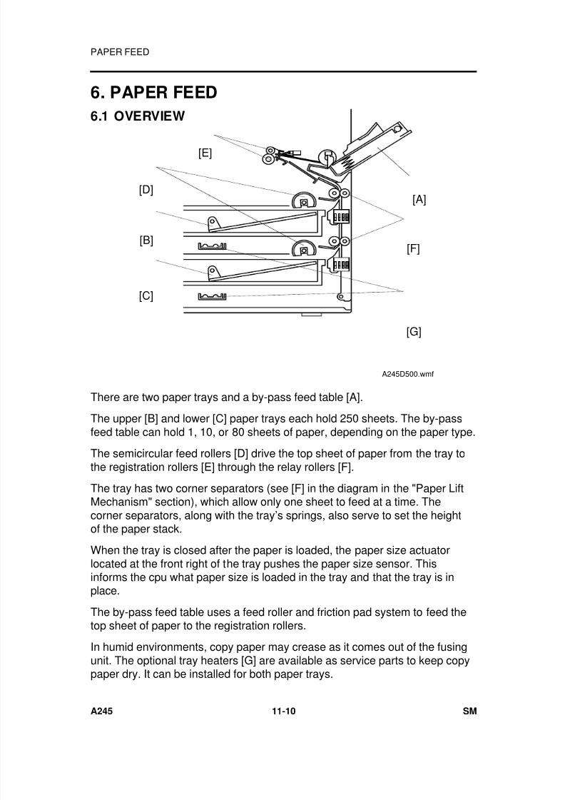
7/18/2019 A219 245 B019 4015 3813 Service
http://slidepdf.com/reader/full/a219-245-b019-4015-3813-service 317/372
6. PAPER FEED
6.1 OVERVIEW
There are two paper trays and a by-pass feed table [A].
The upper [B] and lower [C] paper trays each hold 250 sheets. The by-passfeed table can hold 1, 10, or 80 sheets of paper, depending on the paper type.
The semicircular feed rollers [D] drive the top sheet of paper from the tray tothe registration rollers [E] through the relay rollers [F].
The tray has two corner separators (see [F] in the diagram in the "Paper LiftMechanism" section), which allow only one sheet to feed at a time. Thecorner separators, along with the tray’s springs, also serve to set the heightof the paper stack.
When the tray is closed after the paper is loaded, the paper size actuatorlocated at the front right of the tray pushes the paper size sensor. Thisinforms the cpu what paper size is loaded in the tray and that the tray is inplace.
The by-pass feed table uses a feed roller and friction pad system to feed thetop sheet of paper to the registration rollers.
In humid environments, copy paper may crease as it comes out of the fusingunit. The optional tray heaters [G] are available as service parts to keep copypaper dry. It can be installed for both paper trays.
[A]
[F]
[D]
[B]
[C]
[G]
[E]
A245D500.wmf
PAPER FEED
A245 11-10 SM

7/18/2019 A219 245 B019 4015 3813 Service
http://slidepdf.com/reader/full/a219-245-b019-4015-3813-service 318/372
6.2 PAPER LIFT MECHANISM
When the paper tray [A] is closed after paper is loaded, the release slider [B],
which is mounted on the bottom part of the tray, is pushed by the projection[C] on the main frame and the release slider comes off the bottom plate hook[D].
Once the release slider comes off, the bottom plate is raised by the pressuresprings [E] and the top sheet pushes up the corner separators [F]. This keepsthe stack of paper at the correct height.
[F]
[D]
[E]
[C]
[B]
[A]
[F]
A245D501.wmf
A 2 4 5
C O P I E R
PAPER FEED
SM 11-11 A245
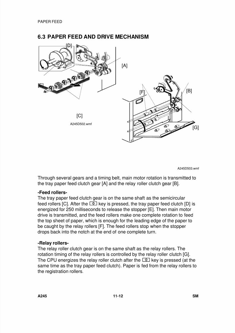
7/18/2019 A219 245 B019 4015 3813 Service
http://slidepdf.com/reader/full/a219-245-b019-4015-3813-service 319/372
6.3 PAPER FEED AND DRIVE MECHANISM
Through several gears and a timing belt, main motor rotation is transmitted tothe tray paper feed clutch gear [A] and the relay roller clutch gear [B].
-Feed rollers-The tray paper feed clutch gear is on the same shaft as the semicircularfeed rollers [C]. After the key is pressed, the tray paper feed clutch [D] isenergized for 250 milliseconds to release the stopper [E]. Then main motordrive is transmitted, and the feed rollers make one complete rotation to feedthe top sheet of paper, which is enough for the leading edge of the paper tobe caught by the relay rollers [F]. The feed rollers stop when the stopper
drops back into the notch at the end of one complete turn.
-Relay rollers-The relay roller clutch gear is on the same shaft as the relay rollers. Therotation timing of the relay rollers is controlled by the relay roller clutch [G].The CPU energizes the relay roller clutch after the key is pressed (at thesame time as the tray paper feed clutch). Paper is fed from the relay rollers tothe registration rollers.
[A]
[E]
[D]
[C]A245D502.wmf
[B]
[G]
[F]
A245D503.wmf
PAPER FEED
A245 11-12 SM
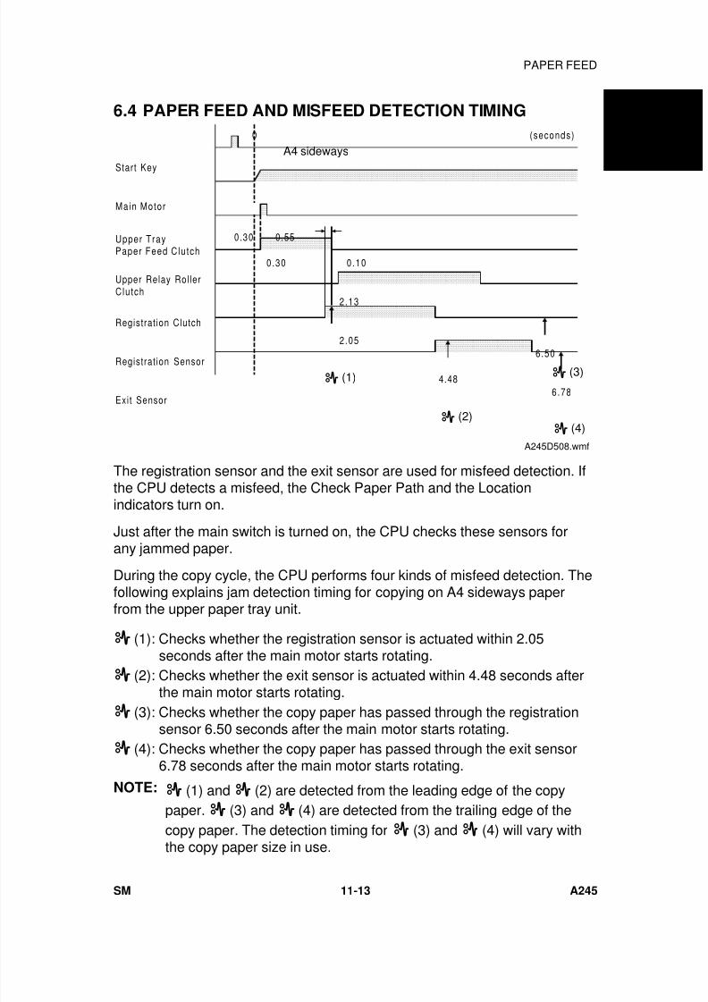
7/18/2019 A219 245 B019 4015 3813 Service
http://slidepdf.com/reader/full/a219-245-b019-4015-3813-service 320/372
6.4 PAPER FEED AND MISFEED DETECTION TIMING
The registration sensor and the exit sensor are used for misfeed detection. Ifthe CPU detects a misfeed, the Check Paper Path and the Locationindicators turn on.
Just after the main switch is turned on, the CPU checks these sensors forany jammed paper.
During the copy cycle, the CPU performs four kinds of misfeed detection. Thefollowing explains jam detection timing for copying on A4 sideways paperfrom the upper paper tray unit.
(1): Checks whether the registration sensor is actuated within 2.05seconds after the main motor starts rotating.
(2): Checks whether the exit sensor is actuated within 4.48 seconds after
the main motor starts rotating. (3): Checks whether the copy paper has passed through the registration
sensor 6.50 seconds after the main motor starts rotating. (4): Checks whether the copy paper has passed through the exit sensor
6.78 seconds after the main motor starts rotating.
NOTE: (1) and (2) are detected from the leading edge of the copypaper. (3) and (4) are detected from the trailing edge of thecopy paper. The detection timing for (3) and (4) will vary withthe copy paper size in use.
Start Key
Main Motor
Upper TrayPaper Feed Clutch
Upper Relay RollerClutch
Registrat ion Clutch
Registrat ion Sensor
Exit Sensor
0
0.30 0.55
0.10
2.13
2.05
4.48
6.50
6.78
(seconds)
0.30
(3)
(4)
(1)
(2)
A4 sideways
A245D508.wmf
A 2 4 5
C O P I E R
PAPER FEED
SM 11-13 A245
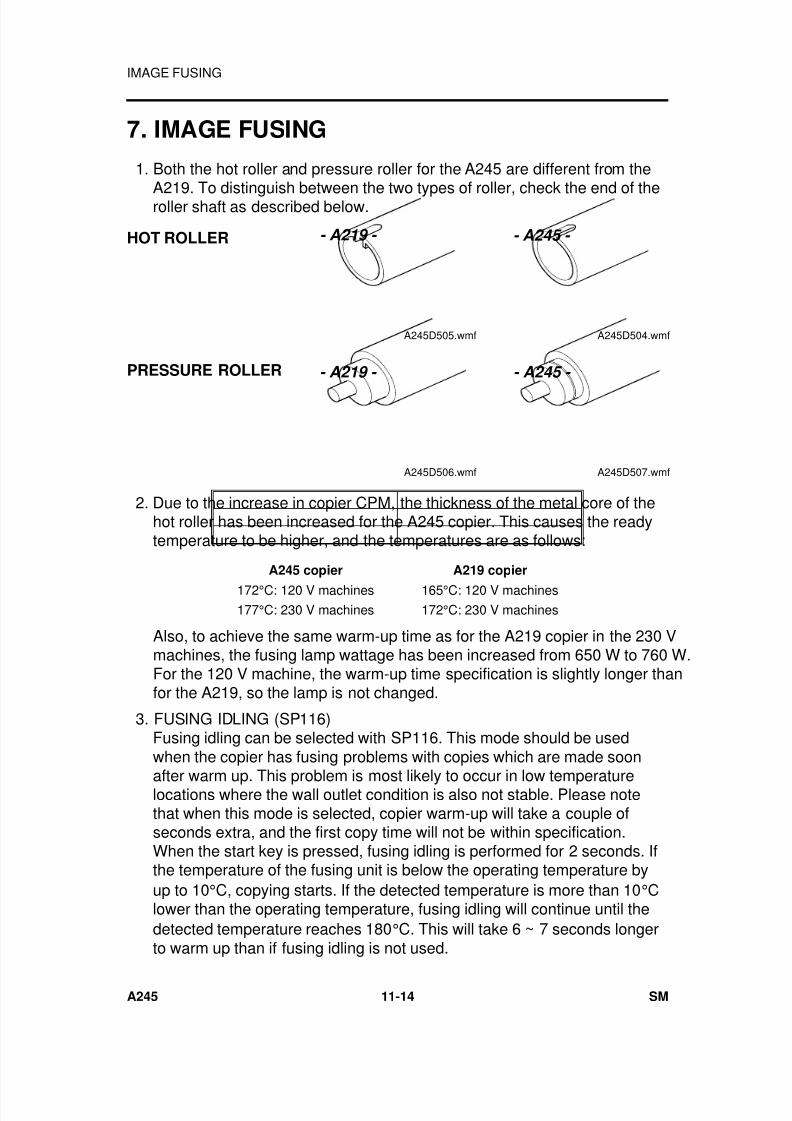
7/18/2019 A219 245 B019 4015 3813 Service
http://slidepdf.com/reader/full/a219-245-b019-4015-3813-service 321/372
7. IMAGE FUSING
1. Both the hot roller and pressure roller for the A245 are different from the
A219. To distinguish between the two types of roller, check the end of theroller shaft as described below.
HOT ROLLER
PRESSURE ROLLER
2. Due to the increase in copier CPM, the thickness of the metal core of thehot roller has been increased for the A245 copier. This causes the readytemperature to be higher, and the temperatures are as follows:
A245 copier A219 copier
172°C: 120 V machines 165°C: 120 V machines177°C: 230 V machines 172°C: 230 V machines
Also, to achieve the same warm-up time as for the A219 copier in the 230 Vmachines, the fusing lamp wattage has been increased from 650 W to 760 W.For the 120 V machine, the warm-up time specification is slightly longer thanfor the A219, so the lamp is not changed.
3. FUSING IDLING (SP116)Fusing idling can be selected with SP116. This mode should be usedwhen the copier has fusing problems with copies which are made soon
after warm up. This problem is most likely to occur in low temperaturelocations where the wall outlet condition is also not stable. Please notethat when this mode is selected, copier warm-up will take a couple ofseconds extra, and the first copy time will not be within specification.When the start key is pressed, fusing idling is performed for 2 seconds. Ifthe temperature of the fusing unit is below the operating temperature byup to 10°C, copying starts. If the detected temperature is more than 10°Clower than the operating temperature, fusing idling will continue until thedetected temperature reaches 180°C. This will take 6 ~ 7 seconds longerto warm up than if fusing idling is not used.
- A245 -
A245D504.wmf
- A219 -
A245D505.wmf
- A219 -
A245D506.wmf
- A245 -
A245D507.wmf
IMAGE FUSING
A245 11-14 SM

7/18/2019 A219 245 B019 4015 3813 Service
http://slidepdf.com/reader/full/a219-245-b019-4015-3813-service 322/372
8. INSTALLATION
8.1 COPIER ACCESSORY CHECK
Check the quantity and condition of the accessories in the box against thefollowings list:
1. Model Name Decal (-10, -22 machines)
2. Symbol Explanation Decal - Multi-language
3. Installation Procedure - Multi-language (-10, -15, -22, -26 machines)
4. Operation Instructions English (-10, -15, -17, -19, -22, -26, -29, -39 machines)
5. NECR - English (-17 machines)
6. NECR - Multi-language (-27, -29, -39 machines)
7. Copy Tray
8. User Survey Card (-17 machines)
9. Paper Set Direction Deal - Multi-language (-22, -26, -27 machines)
A 2 4 5
C O P I E R
INSTALLATION
SM 11-15 A245
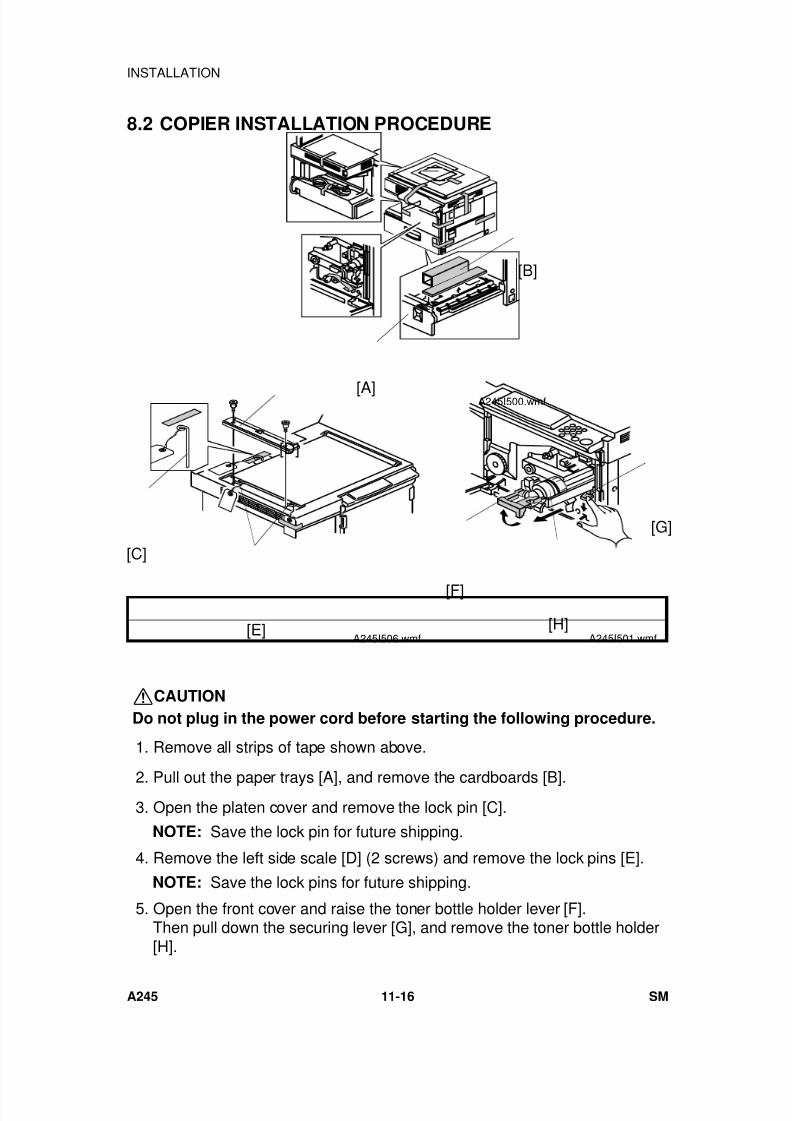
7/18/2019 A219 245 B019 4015 3813 Service
http://slidepdf.com/reader/full/a219-245-b019-4015-3813-service 323/372
8.2 COPIER INSTALLATION PROCEDURE
CAUTION
Do not plug in the power cord before starting the following procedure.
1. Remove all strips of tape shown above.
2. Pull out the paper trays [A], and remove the cardboards [B]. 3. Open the platen cover and remove the lock pin [C].
NOTE: Save the lock pin for future shipping.
4. Remove the left side scale [D] (2 screws) and remove the lock pins [E].
NOTE: Save the lock pins for future shipping.
5. Open the front cover and raise the toner bottle holder lever [F].Then pull down the securing lever [G], and remove the toner bottle holder[H].
[B]
[A] A245I500.wmf
[D]
[C]
[E]A245I506.wmf
[G]
[F]
[H]A245I501.wmf
INSTALLATION
A245 11-16 SM
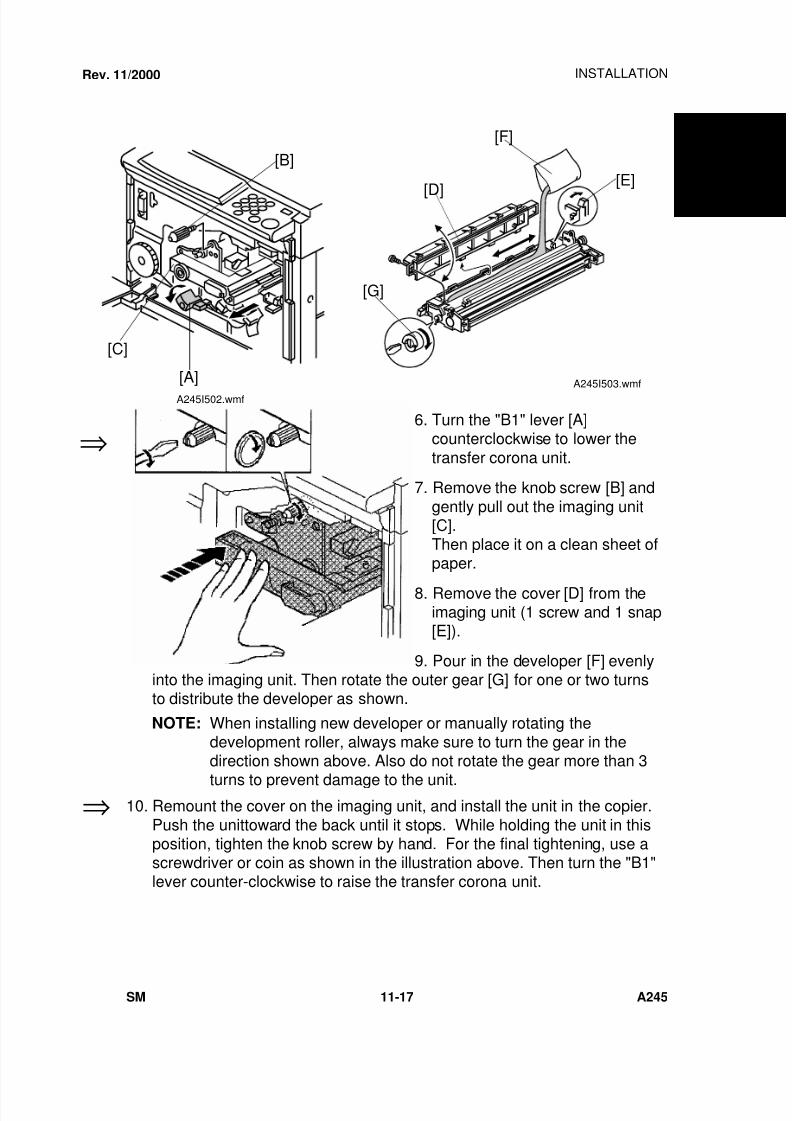
7/18/2019 A219 245 B019 4015 3813 Service
http://slidepdf.com/reader/full/a219-245-b019-4015-3813-service 324/372
6. Turn the "B1" lever [A]counterclockwise to lower the
transfer corona unit.
7. Remove the knob screw [B] and
gently pull out the imaging unit[C].Then place it on a clean sheet ofpaper.
8. Remove the cover [D] from theimaging unit (1 screw and 1 snap[E]).
9. Pour in the developer [F] evenlyinto the imaging unit. Then rotate the outer gear [G] for one or two turnsto distribute the developer as shown.
NOTE: When installing new developer or manually rotating thedevelopment roller, always make sure to turn the gear in thedirection shown above. Also do not rotate the gear more than 3
turns to prevent damage to the unit.
10. Remount the cover on the imaging unit, and install the unit in the copier.
Push the unittoward the back until it stops. While holding the unit in thisposition, tighten the knob screw by hand. For the final tightening, use ascrewdriver or coin as shown in the illustration above. Then turn the "B1"lever counter-clockwise to raise the transfer corona unit.
⇒
⇒
Rev. 11/2000
[B]
[C]
[A]
A245I502.wmf
[F]
[E]
[D]
[G]
A245I503.wmf
A 2 4 5
C O P I E R
INSTALLATION
SM 11-17 A245
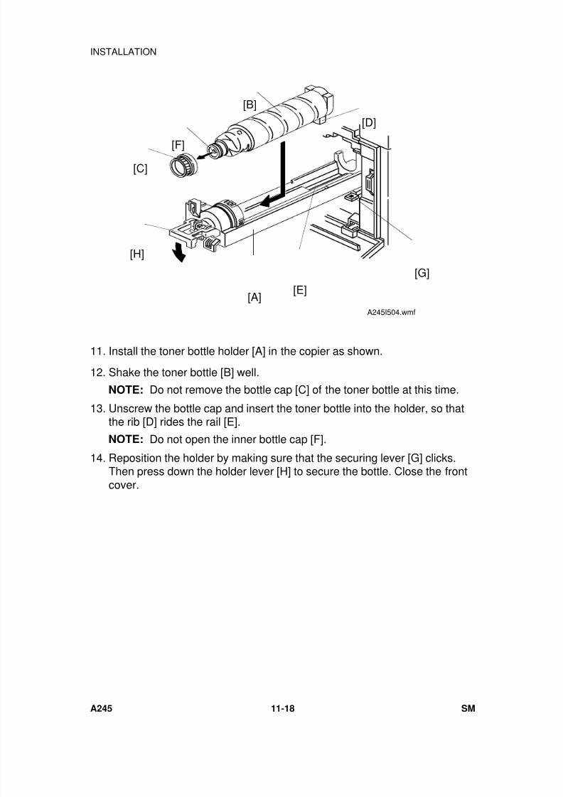
7/18/2019 A219 245 B019 4015 3813 Service
http://slidepdf.com/reader/full/a219-245-b019-4015-3813-service 325/372
11. Install the toner bottle holder [A] in the copier as shown.
12. Shake the toner bottle [B] well.
NOTE: Do not remove the bottle cap [C] of the toner bottle at this time.
13. Unscrew the bottle cap and insert the toner bottle into the holder, so thatthe rib [D] rides the rail [E].
NOTE: Do not open the inner bottle cap [F].
14. Reposition the holder by making sure that the securing lever [G] clicks.Then press down the holder lever [H] to secure the bottle. Close the frontcover.
[B]
[F]
[C]
[H]
[A]
[D]
[G][E]
A245I504.wmf
INSTALLATION
A245 11-18 SM
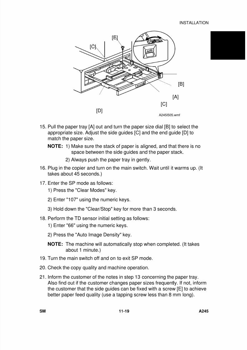
7/18/2019 A219 245 B019 4015 3813 Service
http://slidepdf.com/reader/full/a219-245-b019-4015-3813-service 326/372
15. Pull the paper tray [A] out and turn the paper size dial [B] to select theappropriate size. Adjust the side guides [C] and the end guide [D] tomatch the paper size.
NOTE: 1) Make sure the stack of paper is aligned, and that there is nospace between the side guides and the paper stack.
2) Always push the paper tray in gently.
16. Plug in the copier and turn on the main switch. Wait until it warms up. (Ittakes about 45 seconds.)
17. Enter the SP mode as follows:1) Press the "Clear Modes" key.
2) Enter "107" using the numeric keys.
3) Hold down the "Clear/Stop" key for more than 3 seconds.
18. Perform the TD sensor initial setting as follows:1) Enter "66" using the numeric keys.
2) Press the "Auto Image Density" key.
NOTE: The machine will automatically stop when completed. (It takesabout 1 minute.)
19. Turn the main switch off and on to exit SP mode.
20. Check the copy quality and machine operation.
21. Inform the customer of the notes in step 13 concerning the paper tray.Also find out if the customer changes paper sizes frequently. If not, informthe customer that the side guides can be fixed with a screw [E] to achievebetter paper feed quality (use a tapping screw less than 8 mm long).
[D]
[C]
[B]
[A]
[E]
[C]
A245I505.wmf
A 2 4 5
C O P I E R
INSTALLATION
SM 11-19 A245
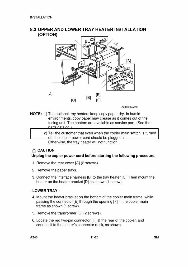
7/18/2019 A219 245 B019 4015 3813 Service
http://slidepdf.com/reader/full/a219-245-b019-4015-3813-service 327/372
8.3 UPPER AND LOWER TRAY HEATER INSTALLATION(OPTION)
NOTE: 1) The optional tray heaters keep copy paper dry. In humidenvironments, copy paper may crease as it comes out of thefusing unit. The heaters are available as service part. (See theparts catalog.)
2) Tell the customer that even when the copier main switch is turned
off, the copier power cord should be plugged in.Otherwise, the tray heater will not function.
CAUTION
Unplug the copier power cord before starting the following procedure.
1. Remove the rear cover [A] (2 screws).
2. Remove the paper trays.
3. Connect the interface harness [B] to the tray heater [C]. Then mount theheater on the heater bracket [D] as shown (1 screw).
- LOWER TRAY -
4. Mount the heater bracket on the bottom of the copier main frame, whilepassing the connector [E] through the opening [F] in the copier mainframe as shown (1 screw).
5. Remove the transformer [G] (2 screws).
6. Locate the red two-pin connector [H] at the rear of the copier, andconnect it to the heater’s connector (red), as shown.
[A]
[H][G]
[E][F]
[B][D]
[C]
A245I507.wmf
INSTALLATION
A245 11-20 SM
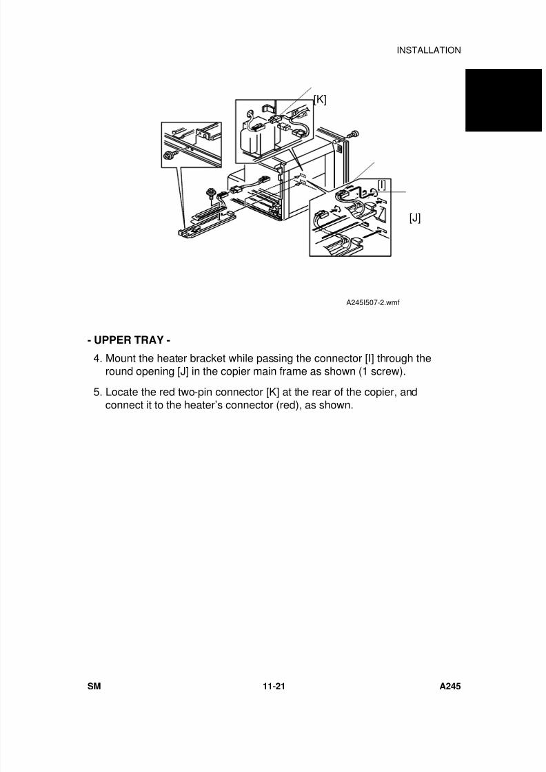
7/18/2019 A219 245 B019 4015 3813 Service
http://slidepdf.com/reader/full/a219-245-b019-4015-3813-service 328/372
- UPPER TRAY -
4. Mount the heater bracket while passing the connector [I] through theround opening [J] in the copier main frame as shown (1 screw).
5. Locate the red two-pin connector [K] at the rear of the copier, and
connect it to the heater’s connector (red), as shown.
[I]
[J]
[K]
A245I507-2.wmf
A 2 4 5
C O P I E R
INSTALLATION
SM 11-21 A245
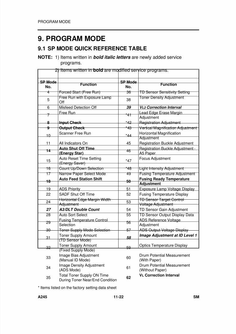
7/18/2019 A219 245 B019 4015 3813 Service
http://slidepdf.com/reader/full/a219-245-b019-4015-3813-service 329/372
9. PROGRAM MODE
9.1 SP MODE QUICK REFERENCE TABLE
NOTE: 1) Items written in bold italic letters are newly added serviceprograms.
2) Items written in bold are modified service programs.
SP ModeNo.
FunctionSP Mode
No.Function
4 Forced Start (Free Run) 36 TD Sensor Sensitivity Setting
5Free Run with Exposure LampOff
38Toner Density Adjustment
6 Misfeed Detection Off 39 V L2 Correction Interval
7Free Run
*41Lead Edge Erase MarginAdjustment
8 Input Check *42 Registration Adjustment9 Output Check *43 Vertical Magnification Adjustment
10Scanner Free Run
*44Horizontal MagnificationAdjustment
11 All Indicators On 45 Registration Buckle Adjustment
14Auto Shut Off Time(Energy Star)
46 Registration Buckle Adjustment -A5 Paper
15Auto Reset Time Setting(Energy Saver)
*47Focus Adjustment
16 Count Up/Down Selection *48 Light Intensity Adjustment
17 Narrow Paper Select Mode 49 Fusing Temperature Adjustment18
Auto Feed Station Shift50
Fusing Ready TemperatureAdjustment
19 ADS Priority 51 Exposure Lamp Voltage Display22 SADF Shut Off Time 52 Fusing Temperature Display
24Horizontal Edge Margin WidthAdjustment
53TD Sensor Target ControlVoltage Adjustment
27 A3/DLT Double Count 54 TD Sensor Gain Adjustment28 Auto Sort Select 55 TD Sensor Output Display Data
29Fusing Temperature ControlSelection
56ADS Reference VoltageAdjustment
30 Toner Supply Mode Selection 57 ADS Output Voltage Display31
Toner Supply Amount(TD Sensor Mode)
58 Image Adjustment at ID Level 1
32 Toner Supply Amount(Fixed Supply Mode)
59 Optics Temperature Display
33Image Bias Adjustment(Manual ID Mode)
60Drum Potential Measurement(With Paper)
34Image Density Adjustment(ADS Mode)
61Drum Potential Measurement(Without Paper)
35Total Toner Supply ON TimeDuring Toner Near/End Condition
62VL Correction Interval
* Items listed on the factory setting data sheet
PROGRAM MODE
A245 11-22 SM
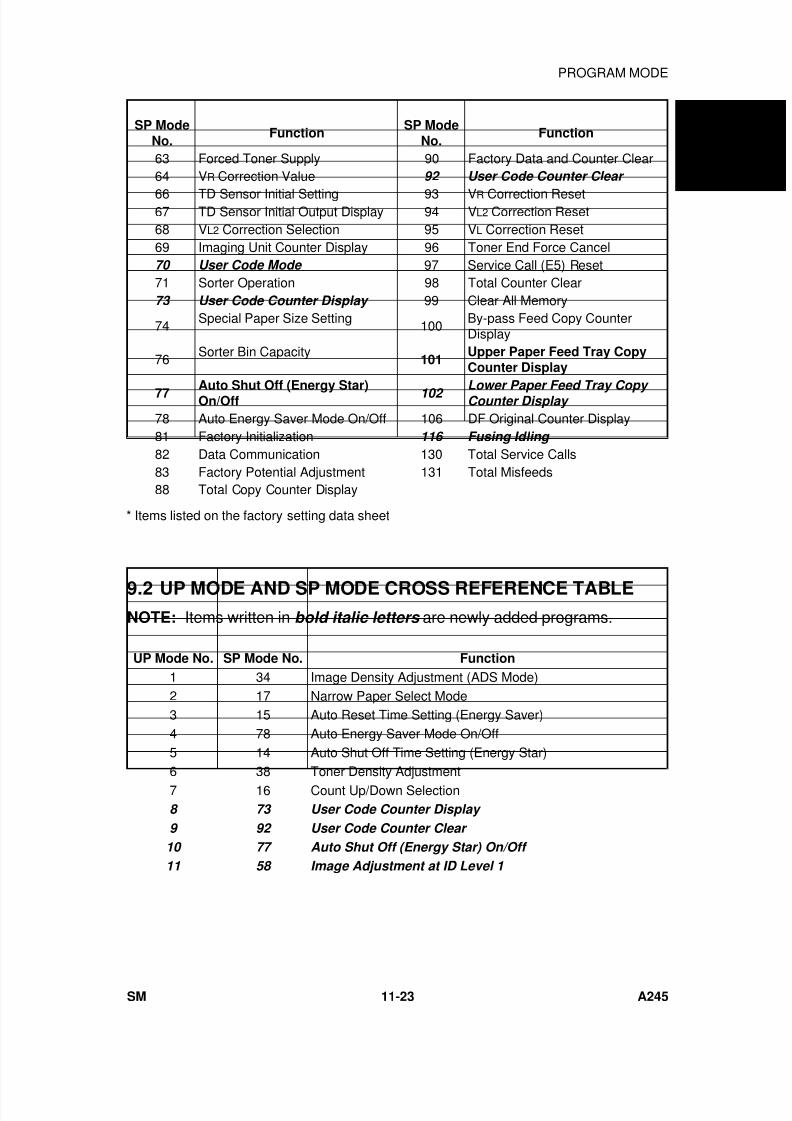
7/18/2019 A219 245 B019 4015 3813 Service
http://slidepdf.com/reader/full/a219-245-b019-4015-3813-service 330/372
SP ModeNo.
FunctionSP Mode
No.Function
63 Forced Toner Supply 90 Factory Data and Counter Clear64 VR Correction Value 92 User Code Counter Clear
66 TD Sensor Initial Setting 93 VR Correction Reset67 TD Sensor Initial Output Display 94 VL2 Correction Reset68 VL2 Correction Selection 95 VL Correction Reset69 Imaging Unit Counter Display 96 Toner End Force Cancel70 User Code Mode 97 Service Call (E5) Reset71 Sorter Operation 98 Total Counter Clear73 User Code Counter Display 99 Clear All Memory
74Special Paper Size Setting
100By-pass Feed Copy CounterDisplay
76Sorter Bin Capacity
101Upper Paper Feed Tray CopyCounter Display
77 Auto Shut Off (Energy Star)On/Off
102 Lower Paper Feed Tray Copy Counter Display
78 Auto Energy Saver Mode On/Off 106 DF Original Counter Display81 Factory Initialization 116 Fusing Idling
82 Data Communication 130 Total Service Calls83 Factory Potential Adjustment 131 Total Misfeeds88 Total Copy Counter Display
9.2 UP MODE AND SP MODE CROSS REFERENCE TABLE
NOTE: Items written in bold italic letters are newly added programs.
UP Mode No. SP Mode No. Function
1 34 Image Density Adjustment (ADS Mode)2 17 Narrow Paper Select Mode3 15 Auto Reset Time Setting (Energy Saver)4 78 Auto Energy Saver Mode On/Off5 14 Auto Shut Off Time Setting (Energy Star)
6 38 Toner Density Adjustment7 16 Count Up/Down Selection8 73 User Code Counter Display
9 92 User Code Counter Clear
10 77 Auto Shut Off (Energy Star) On/Off
11 58 Image Adjustment at ID Level 1
* Items listed on the factory setting data sheet
A 2 4 5
C O P I E R
PROGRAM MODE
SM 11-23 A245
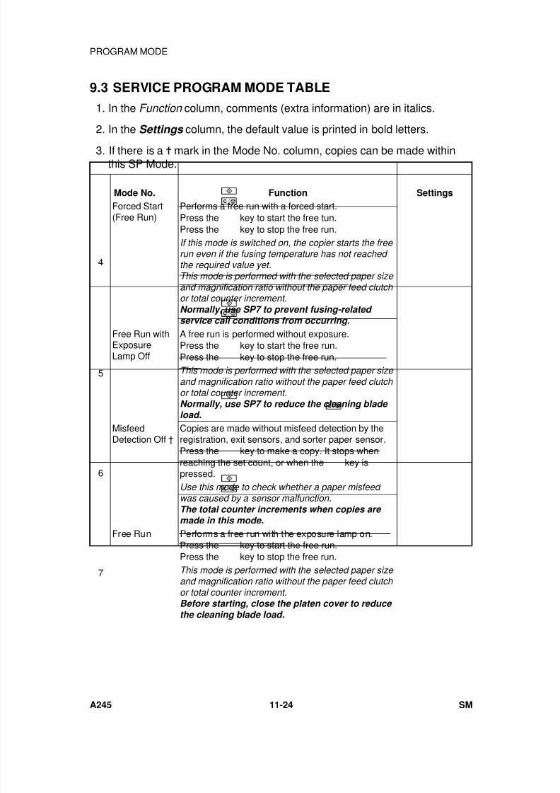
7/18/2019 A219 245 B019 4015 3813 Service
http://slidepdf.com/reader/full/a219-245-b019-4015-3813-service 331/372
9.3 SERVICE PROGRAM MODE TABLE
1. In the Function column, comments (extra information) are in italics.
2. In the Settings column, the default value is printed in bold letters.
3. If there is a mark in the Mode No. column, copies can be made withinthis SP Mode.
Mode No. Function Settings
4
Forced Start(Free Run)
Performs a free run with a forced start.Press the
key to start the free tun.Press the key to stop the free run.If this mode is switched on, the copier starts the free run even if the fusing temperature has not reached the required value yet.
This mode is performed with the selected paper size and magnification ratio without the paper feed clutch or total counter increment.Normally, use SP7 to prevent fusing-related service call conditions from occurring.
5
Free Run withExposureLamp Off
A free run is performed without exposure.Press the
key to start the free run.Press the
key to stop the free run.This mode is performed with the selected paper size and magnification ratio without the paper feed clutch or total counter increment.Normally, use SP7 to reduce the cleaning blade
load.
6
MisfeedDetection Off †
Copies are made without misfeed detection by theregistration, exit sensors, and sorter paper sensor.Press the
key to make a copy. It stops whenreaching the set count, or when the
key ispressed.Use this mode to check whether a paper misfeed was caused by a sensor malfunction.The total counter increments when copies are made in this mode.
7
Free Run Performs a free run with the exposure lamp on.Press the
key to start the free run.Press the
key to stop the free run.This mode is performed with the selected paper size and magnification ratio without the paper feed clutch or total counter increment.Before starting, close the platen cover to reduce the cleaning blade load.
PROGRAM MODE
A245 11-24 SM
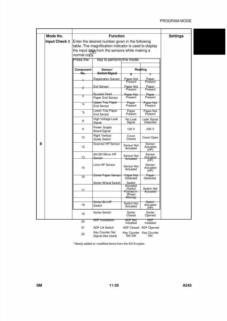
7/18/2019 A219 245 B019 4015 3813 Service
http://slidepdf.com/reader/full/a219-245-b019-4015-3813-service 332/372
Mode No. Function Settings
8
Input Check † Enter the desired number given in the followingtable. The magnification indicator is used to displaythe input data from the sensors while making a
normal copy.Press the
key to perform this mode.
* Newly added or modified items from the A219 copier.
ComponentNo.
Sensor/Switch/Signal
Reading
0 1
1 Registration Sensor Paper NotPresent
PaperPresent
2 Exit Sensor Paper NotPresent
PaperPresent
3By-pass FeedPaper End Sensor
Paper NotPresent
PaperPresent
*4Upper Tray PaperEnd Sensor
PaperPresent
Paper NotPresent
*5 Lower Tray PaperEnd Sensor PaperPresent Paper NotPresent
8High Voltage LeakSignal
No LeakSignal
Leak SignalDetected
9 Power SupplyBoard Signal
120 V 230 V
10Right VerticalGuide Switch
CoverClosed Cover Open
12Scanner HP Sensor Sensor Not
ActuatedSensor
Actuated(HP)
134th/5th Mirror HPSensor
Sensor NotActuated
SensorActuated
(HP)
14Lens HP Sensor
Sensor NotActuatedSensor
Actuated(HP)
16 Sorter Paper Sensor Paper NotDetected
PaperDetected
17
Sorter Wheel Switch SwitchActuated(Switch
Pushed in:Wheel
Moving)
Switch NotActuated
18Sorter Bin HPSwitch
Switch NotActuated
SwitchActuated
(HP)
19 Sorter Switch SorterClosed
SorterOpened
20
ADF Installation ADF Not
Installed
ADF
Installed21 ADF Lift Switch ADF Closed ADF Opened
22Key Counter SetSignal (Not Used)
Key CounterNot Set
Key CounterSet
A 2 4 5
C O P I E R
PROGRAM MODE
SM 11-25 A245
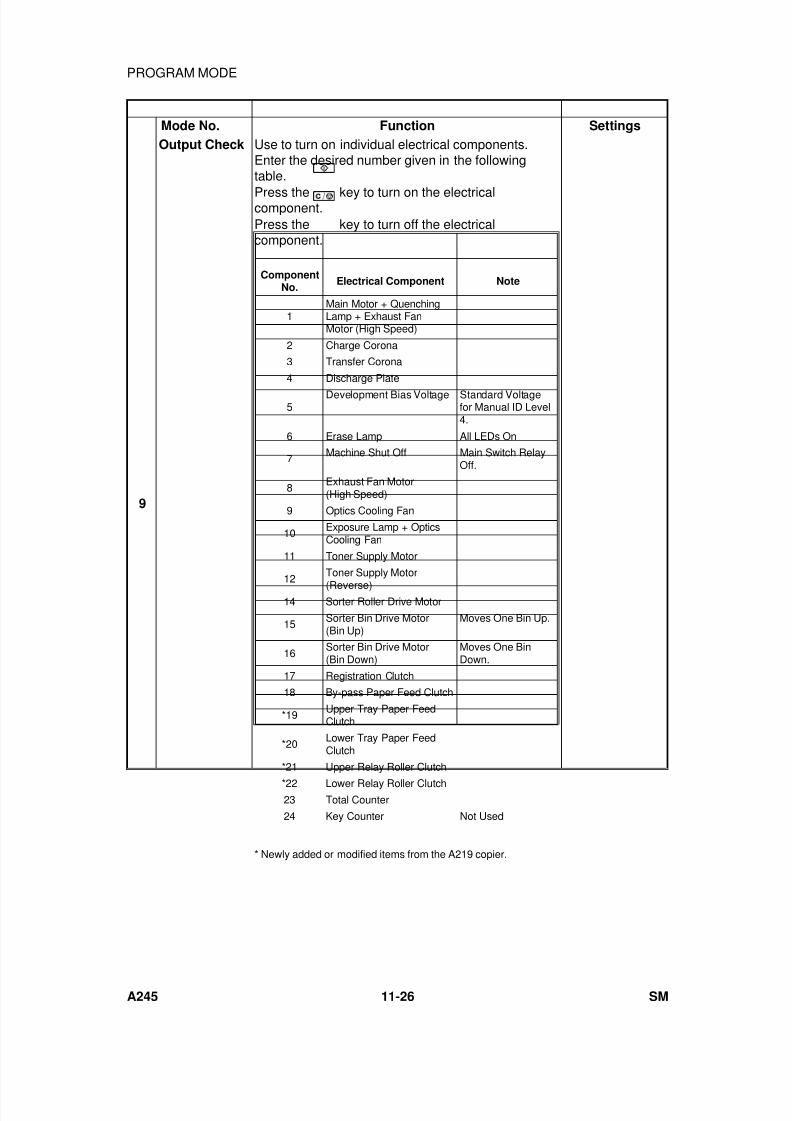
7/18/2019 A219 245 B019 4015 3813 Service
http://slidepdf.com/reader/full/a219-245-b019-4015-3813-service 333/372
Mode No. Function Settings
9
Output Check Use to turn on individual electrical components.Enter the desired number given in the followingtable.
Press the
key to turn on the electricalcomponent.Press the
key to turn off the electricalcomponent.
* Newly added or modified items from the A219 copier.
ComponentNo.
Electrical Component Note
1Main Motor + QuenchingLamp + Exhaust FanMotor (High Speed)
2 Charge Corona
3 Transfer Corona
4 Discharge Plate
5Development Bias Voltage Standard Voltage
for Manual ID Level4.
6 Erase Lamp All LEDs On
7Machine Shut Off Main Switch Relay
Off.
8Exhaust Fan Motor(High Speed)
9 Optics Cooling Fan
10Exposure Lamp + OpticsCooling Fan
11 Toner Supply Motor
12
Toner Supply Motor
(Reverse)14 Sorter Roller Drive Motor
15Sorter Bin Drive Motor(Bin Up)
Moves One Bin Up.
16Sorter Bin Drive Motor(Bin Down)
Moves One BinDown.
17 Registration Clutch
18 By-pass Paper Feed Clutch
*19Upper Tray Paper FeedClutch
*20Lower Tray Paper FeedClutch
*21 Upper Relay Roller Clutch
*22 Lower Relay Roller Clutch23 Total Counter
24 Key Counter Not Used
PROGRAM MODE
A245 11-26 SM
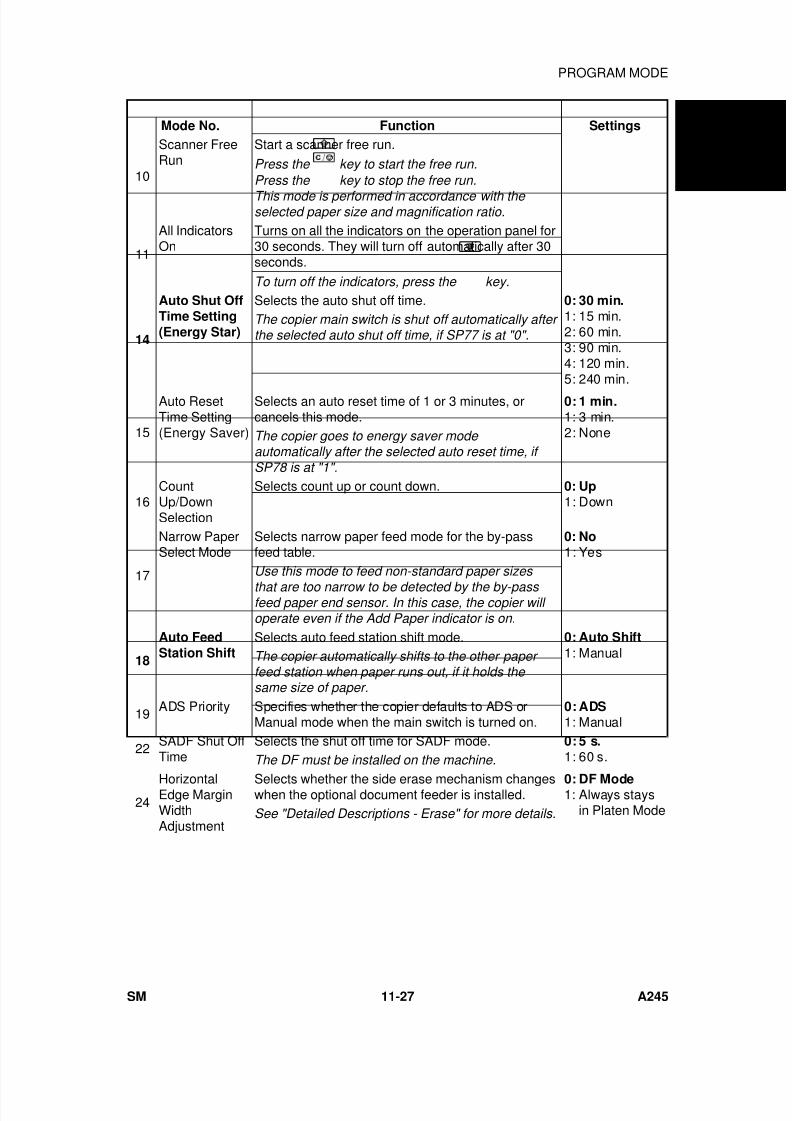
7/18/2019 A219 245 B019 4015 3813 Service
http://slidepdf.com/reader/full/a219-245-b019-4015-3813-service 334/372
Mode No. Function Settings
10
Scanner FreeRun
Start a scanner free run.
Press the key to start the free run.
Press the
key to stop the free run.
This mode is performed in accordance with the selected paper size and magnification ratio.
11
All IndicatorsOn
Turns on all the indicators on the operation panel for30 seconds. They will turn off automatically after 30seconds.
To turn off the indicators, press the
key.
14
Auto Shut OffTime Setting(Energy Star)
Selects the auto shut off time. 0: 30 min.1: 15 min.2: 60 min.3: 90 min.4: 120 min.5: 240 min.
The copier main switch is shut off automatically after the selected auto shut off time, if SP77 is at "0".
15
Auto ResetTime Setting(Energy Saver)
Selects an auto reset time of 1 or 3 minutes, orcancels this mode.
0: 1 min.1: 3 min.2: NoneThe copier goes to energy saver mode
automatically after the selected auto reset time, if SP78 is at "1".
16CountUp/DownSelection
Selects count up or count down. 0: Up1: Down
17
Narrow PaperSelect Mode
Selects narrow paper feed mode for the by-passfeed table.
0: No1: Yes
Use this mode to feed non-standard paper sizes
that are too narrow to be detected by the by-pass feed paper end sensor. In this case, the copier will operate even if the Add Paper indicator is on.
18
Auto FeedStation Shift
Selects auto feed station shift mode. 0: Auto Shift
1: ManualThe copier automatically shifts to the other paper feed station when paper runs out, if it holds the same size of paper.
19 ADS Priority Specifies whether the copier defaults to ADS orManual mode when the main switch is turned on.
0: ADS1: Manual
22 SADF Shut OffTime
Selects the shut off time for SADF mode. 0: 5 s.1: 60 s.The DF must be installed on the machine.
24HorizontalEdge MarginWidthAdjustment
Selects whether the side erase mechanism changeswhen the optional document feeder is installed.
0: DF Mode1: Always stays
in Platen ModeSee "Detailed Descriptions - Erase" for more details.
A 2 4 5
C O P I E R
PROGRAM MODE
SM 11-27 A245
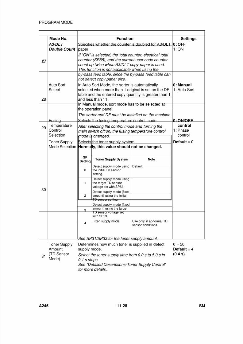
7/18/2019 A219 245 B019 4015 3813 Service
http://slidepdf.com/reader/full/a219-245-b019-4015-3813-service 335/372
Mode No. Function Settings
27
A3/DLT Double Count
Specifies whether the counter is doubled for A3/DLTpaper.
0: OFF1: ON
If "ON" is selected, the total counter, electrical total
counter (SP88), and the current user code counter count up twice when A3/DLT copy paper is used.This function is not applicable when using the by-pass feed table, since the by-pass feed table can not detect copy paper size.
28
Auto SortSelect
In Auto Sort Mode, the sorter is automaticallyselected when more than 1 original is set on the DFtable and the entered copy quantity is greater than 1and less than 11.In Manual mode, sort mode has to be selected atthe operation panel.
0: Manual1: Auto Sort
The sorter and DF must be installed on the machine.
29FusingTemperatureControlSelection
Selects the fusing temperature control mode. 0: ON/OFFcontrol
1: Phasecontrol
After selecting the control mode and turning the main switch off/on, the fusing temperature control mode is changed.
30
Toner SupplyMode Selection
Selects the toner supply system.Normally, this value should not be changed.
Default = 0
See SP31/SP32 for the toner supply amount.
31
Toner SupplyAmount(TD SensorMode)
Determines how much toner is supplied in detectsupply mode.
0 ~ 50Default = 4(0.4 s)Select the toner supply time from 0.0 s to 5.0 s in
0.1 s steps.See "Detailed Descriptions-Toner Supply Control" for more details.
SPSetting
Toner Supply System Note
0Detect supply mode usingthe initial TD sensorsetting.
Default
1 Detect supply mode usingthe target TD sensorvoltage set with SP53.
2Detect supply mode (fixedamount) using the initialTD sensor setting.
3
Detect supply mode (fixedamount) using the targetTD sensor voltage setwith SP53.
4Fixed supply mode. Use only in abnormal TD
sensor conditions.
PROGRAM MODE
A245 11-28 SM
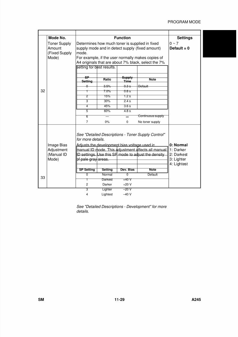
7/18/2019 A219 245 B019 4015 3813 Service
http://slidepdf.com/reader/full/a219-245-b019-4015-3813-service 336/372
Mode No. Function Settings
32
Toner SupplyAmount(Fixed Supply
Mode)
Determines how much toner is supplied in fixedsupply mode and in detect supply (fixed amount)mode.
For example, if the user normally makes copies ofA4 originals that are about 7% black, select the 7%setting for best results.
0 ~ 7Default = 0
See "Detailed Descriptions - Toner Supply Control" for more details.
33
Image BiasAdjustment(Manual IDMode)
Adjusts the development bias voltage used inmanual ID mode. This adjustment affects all manualID settings. Use this SP mode to adjust the densityof pale gray areas.
0: Normal
1: Darker2: Darkest3: Lighter4: Lightest
See "Detailed Descriptions - Development" for more details.
SPSetting
RatioSupplyTime
Note
0 3.5% 0.3 s Default
1 7.0% 0.6 s
2 15% 1.2 s
3 30% 2.4 s
4 45% 3.6 s
5 60% 4.8 s
6 — ∞ Continuous supply7 0% 0 No toner supply
SP Setting Setting Dev. Bias Note
0 Normal 0 Default1 Darkest +40 V
2 Darker +20 V
3 Lighter –20 V
4 Lightest –40 V
A 2 4 5
C O P I E R
PROGRAM MODE
SM 11-29 A245
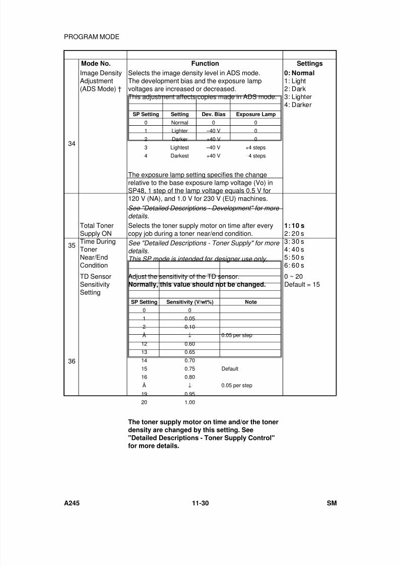
7/18/2019 A219 245 B019 4015 3813 Service
http://slidepdf.com/reader/full/a219-245-b019-4015-3813-service 337/372
Mode No. Function Settings
34
Image DensityAdjustment(ADS Mode) †
Selects the image density level in ADS mode.The development bias and the exposure lampvoltages are increased or decreased.
This adjustment affects copies made in ADS mode.
The exposure lamp setting specifies the changerelative to the base exposure lamp voltage (Vo) inSP48, 1 step of the lamp voltage equals 0.5 V for
120 V (NA), and 1.0 V for 230 V (EU) machines.
0: Normal1: Light2: Dark
3: Lighter4: Darker
See "Detailed Descriptions - Development" for more details.
35
Total TonerSupply ONTime DuringTonerNear/EndCondition
Selects the toner supply motor on time after everycopy job during a toner near/end condition.
1: 10 s2: 20 s3: 30 s4: 40 s5: 50 s6: 60 s
See "Detailed Descriptions - Toner Supply" for more details.This SP mode is intended for designer use only.
36
TD SensorSensitivity
Setting
Adjust the sensitivity of the TD sensor.Normally, this value should not be changed.
The toner supply motor on time and/or the tonerdensity are changed by this setting. See"Detailed Descriptions - Toner Supply Control"for more details.
0 ~ 20Default = 15
SP Setting Setting Dev. Bias Exposure Lamp
0 Normal 0 0
1 Lighter –40 V 0
2 Darker +40 V 0
3 Lightest –40 V +4 steps
4 Darkest +40 V –4 steps
SP Setting Sensitivity (V/wt%) Note
0 0
1 0.05
2 0.10
Å ↓ 0.05 per step
12 0.60
13 0.65
14 0.70
15 0.75 Default
16 0.80
Å ↓ 0.05 per step
19 0.9520 1.00
PROGRAM MODE
A245 11-30 SM
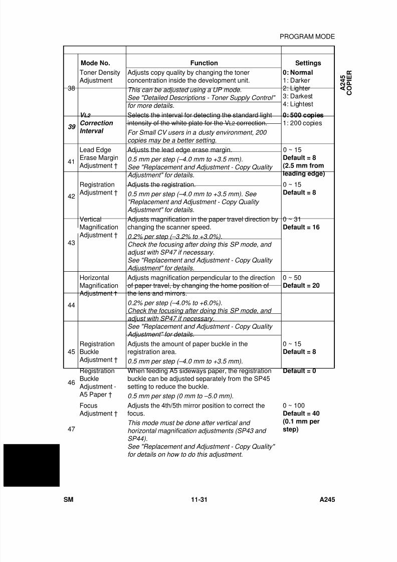
7/18/2019 A219 245 B019 4015 3813 Service
http://slidepdf.com/reader/full/a219-245-b019-4015-3813-service 338/372
Mode No. Function Settings
38
Toner DensityAdjustment
Adjusts copy quality by changing the tonerconcentration inside the development unit.
0: Normal1: Darker2: Lighter
3: Darkest4: Lightest
This can be adjusted using a UP mode.
See "Detailed Descriptions - Toner Supply Control" for more details.
39
V L2
Correction Interval
Selects the interval for detecting the standard lightintensity of the white plate for the VL2 correction.
0: 500 copies1: 200 copies
For Small CV users in a dusty environment, 200 copies may be a better setting.
41
Lead EdgeErase MarginAdjustment †
Adjusts the lead edge erase margin. 0 ~ 15Default = 8(2.5 mm fromleading edge)
0.5 mm per step (–4.0 mm to +3.5 mm).See "Replacement and Adjustment - Copy Quality Adjustment" for details.
42
Registration
Adjustment †
Adjusts the registration. 0 ~ 15
Default = 80.5 mm per step (–4.0 mm to +3.5 mm). See "Replacement and Adjustment - Copy Quality Adjustment" for details.
43
VerticalMagnificationAdjustment †
Adjusts magnification in the paper travel direction bychanging the scanner speed.
0 ~ 31Default = 16
0.2% per step (–3.2% to +3.0%).Check the focusing after doing this SP mode, and adjust with SP47 if necessary.See "Replacement and Adjustment - Copy Quality Adjustment" for details.
44
HorizontalMagnification
Adjustment
Adjusts magnification perpendicular to the directionof paper travel, by changing the home position of
the lens and mirrors.
0 ~ 50Default = 20
0.2% per step (–4.0% to +6.0%).Check the focusing after doing this SP mode, and adjust with SP47 if necessary.See "Replacement and Adjustment - Copy Quality Adjustment" for details.
45RegistrationBuckleAdjustment †
Adjusts the amount of paper buckle in theregistration area.
0 ~ 15Default = 8
0.5 mm per step (–4.0 mm to +3.5 mm).
46
RegistrationBuckleAdjustment -A5 Paper †
When feeding A5 sideways paper, the registrationbuckle can be adjusted separately from the SP45setting to reduce the buckle.
Default = 0
0.5 mm per step (0 mm to –5.0 mm).
47
FocusAdjustment †
Adjusts the 4th/5th mirror position to correct thefocus.
0 ~ 100Default = 40(0.1 mm perstep)
This mode must be done after vertical and horizontal magnification adjustments (SP43 and SP44).See "Replacement and Adjustment - Copy Quality" for details on how to do this adjustment.
A 2 4 5
C O P I E R
PROGRAM MODE
SM 11-31 A245
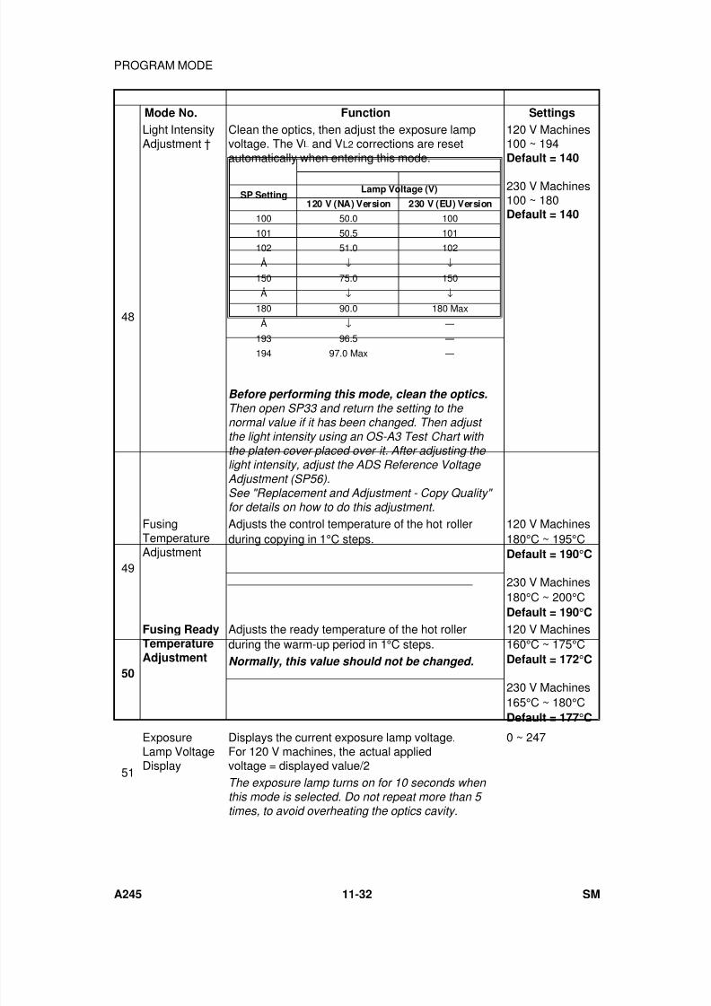
7/18/2019 A219 245 B019 4015 3813 Service
http://slidepdf.com/reader/full/a219-245-b019-4015-3813-service 339/372
Mode No. Function Settings
48
Light IntensityAdjustment †
Clean the optics, then adjust the exposure lampvoltage. The VL and VL2 corrections are resetautomatically when entering this mode.
120 V Machines100 ~ 194Default = 140
230 V Machines100 ~ 180Default = 140
Before performing this mode, clean the optics.Then open SP33 and return the setting to the normal value if it has been changed. Then adjust the light intensity using an OS-A3 Test Chart with the platen cover placed over it. After adjusting the light intensity, adjust the ADS Reference Voltage Adjustment (SP56).See "Replacement and Adjustment - Copy Quality" for details on how to do this adjustment.
49
FusingTemperatureAdjustment
Adjusts the control temperature of the hot rollerduring copying in 1°C steps.
120 V Machines180°C ~ 195°CDefault = 190°C
230 V Machines180°C ~ 200°CDefault = 190°C
50
Fusing ReadyTemperatureAdjustment
Adjusts the ready temperature of the hot rollerduring the warm-up period in 1°C steps.
120 V Machines160°C ~ 175°CDefault = 172°C
230 V Machines
165°C ~ 180°CDefault = 177°C
Normally, this value should not be changed.
51
ExposureLamp VoltageDisplay
Displays the current exposure lamp voltage.For 120 V machines, the actual appliedvoltage = displayed value/2
0 ~ 247
The exposure lamp turns on for 10 seconds when this mode is selected. Do not repeat more than 5 times, to avoid overheating the optics cavity.
SP SettingLamp Voltage (V)
120 V (NA) Version 230 V (EU) Version
100 50.0 100
101 50.5 101
102 51.0 102
Å ↓ ↓
150 75.0 150
Å ↓ ↓
180 90.0 180 Max
Å ↓ —
193 96.5 —
194 97.0 Max —
PROGRAM MODE
A245 11-32 SM

7/18/2019 A219 245 B019 4015 3813 Service
http://slidepdf.com/reader/full/a219-245-b019-4015-3813-service 340/372
Mode No. Function Settings
52
FusingTemperatureDisplay †
Displays the fusing temperature detected by thefusing thermistor.Press the
key to monitor the temperature
during the normal copy cycle.
53
TD SensorTarget ControlVoltageAdjustment
If the setting of SP30 (Toner Supply ModeSelection) is 1 or 3, this value is used for the TDsensor target voltage.
1 ~ 200Default = 97(0.02 V per step)
Normally, this value should not be changed.
54TD SensorGainAdjustment
When the TD Sensor initial setting is performed, thismode is adjusted automatically.
0 ~ 255Default = 102(0.04 V per step)Normally, this value should not be changed.
55
TD SensorOutput DisplayData †
Displays the TD sensor output voltage.Press the
key to monitor the output voltageduring the normal copy cycle.The output voltage will display "0" when this mode isaccessed after turning on the main switch withoutmaking any copies.
(0.02 V perstep) x Data
56
ADSReferenceVoltageAdjustment
Adjusts the ADS reference voltage.After adjusting the light intensity (SP48), place 5 sheets of A4(LT) white paper on the exposure glass and select this mode. Adjust the ADS voltage to 2.5
V ± 0.1 V using VR101 on the main control board.
57
ADS OutputVoltageDisplay †
Displays the ADS output voltage.Press the key to monitor the output voltageduring the normal copy cycle.For only this SP mode, the copies are made with the
ADS mode (other SP modes use manual ID level 4).
58
Image Adjustment at ID Level 1
Adjusts the image density at ID level 1 by changingthe development bias voltage.
0: Normal1: Darker
59
OpticsTemperatureDisplay †
Displays the optics temperature detected by theoptics thermistor.
Press the
key to monitor the temperature
during the normal copy cycle.
60Drum PotentialMeasurement(With Paper)
Factory use only.
61Drum PotentialMeasurement(Without Paper)
Factory use only.
SP Setting Setting Dev. Bias Note
0 Normal –200 Default
1 Darker –140
A 2 4 5
C O P I E R
PROGRAM MODE
SM 11-33 A245
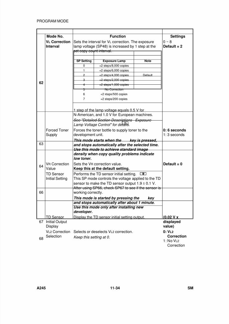
7/18/2019 A219 245 B019 4015 3813 Service
http://slidepdf.com/reader/full/a219-245-b019-4015-3813-service 341/372
Mode No. Function Settings
62
VL CorrectionInterval
Sets the interval for VL correction. The exposurelamp voltage (SP48) is increased by 1 step at theset copy count interval.
1 step of the lamp voltage equals 0.5 V forN-American, and 1.0 V for European machines.
0 ~ 8Default = 2
See "Detailed Section Descriptions - Exposure Lamp Voltage Control" for details.
63
Forced TonerSupply
Forces the toner bottle to supply toner to thedevelopment unit.
0: 6 seconds1: 3 seconds
This mode starts when the
key is pressed,and stops automatically after the selected time.Use this mode to achieve standard image density when copy quality problems indicate low toner.
64VR Correction
Value
Sets the VR correction value.
Keep this at the default setting.
Default = 0
66
TD SensorInitial Setting
Performs the TD sensor initial setting.This SP mode controls the voltage applied to the TDsensor to make the TD sensor output 1.9 ± 0.1 V.After using SP66, check SP67 to see if the sensor isworking correctly.
This mode is started by pressing the
key and stops automatically after about 1 minute.Use this mode only after installing new developer.
67TD SensorInitial Output
Display
Display the TD sensor initial setting output. (0.02 V xdisplayed
value)
68
VL2 CorrectionSelection
Selects or deselects VL2 correction. 0: VL2
Correction1: No VL2
Correction
Keep this setting at 0.
SP Setting Exposure Lamp Note
0 +2 steps/8,000 copies
1 +2 steps/6,000 copies
2 +2 steps/4,000 copies Default
3 +2 steps/2,000 copies
4 +2 steps/1,000 copies
5 No Correction
6 +2 steps/500 copies
7 +2 steps/200 copies
PROGRAM MODE
A245 11-34 SM
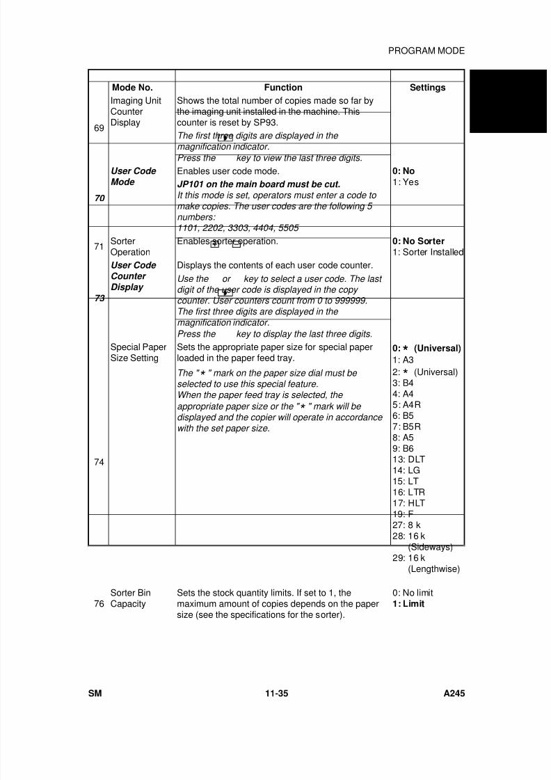
7/18/2019 A219 245 B019 4015 3813 Service
http://slidepdf.com/reader/full/a219-245-b019-4015-3813-service 342/372
Mode No. Function Settings
69
Imaging UnitCounterDisplay
Shows the total number of copies made so far bythe imaging unit installed in the machine. Thiscounter is reset by SP93.
The first three digits are displayed in the magnification indicator.
Press the
key to view the last three digits.
70
User Code Mode
Enables user code mode. 0: No
1: YesJP101 on the main board must be cut.It this mode is set, operators must enter a code to make copies. The user codes are the following 5 numbers: 1101, 2202, 3303, 4404, 5505
71SorterOperation
Enables sorter operation. 0: No Sorter1: Sorter Installed
73
User Code Counter Display
Displays the contents of each user code counter.
Use the or key to select a user code. The last digit of the user code is displayed in the copy counter. User counters count from 0 to 999999.The first three digits are displayed in the magnification indicator.
Press the
key to display the last three digits.
74
Special PaperSize Setting
Sets the appropriate paper size for special paperloaded in the paper feed tray.
0: * (Universal)
1: A32: * (Universal)3: B44: A4
5: A4R6: B57: B5R8: A59: B613: DLT14: LG15: LT16: LTR17: HLT19: F27: 8 k28: 16 k
(Sideways)29: 16 k
(Lengthwise)
The " * " mark on the paper size dial must be selected to use this special feature.When the paper feed tray is selected, the
appropriate paper size or the " * " mark will be displayed and the copier will operate in accordance with the set paper size.
76Sorter BinCapacity
Sets the stock quantity limits. If set to 1, themaximum amount of copies depends on the papersize (see the specifications for the sorter).
0: No limit1: Limit
A 2 4 5
C O P I E R
PROGRAM MODE
SM 11-35 A245
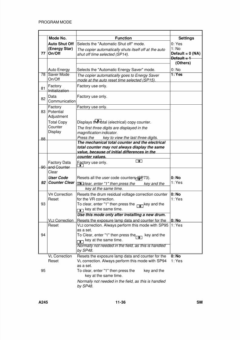
7/18/2019 A219 245 B019 4015 3813 Service
http://slidepdf.com/reader/full/a219-245-b019-4015-3813-service 343/372
Mode No. Function Settings
77
Auto Shut Off(Energy Star)On/Off
Selects the "Automatic Shut off" mode. 0: Yes1: NoDefault = 0 (NA)
Default = 1(Others)
The copier automatically shuts itself off at the auto shut off time selected (SP14).
78Auto EnergySaver ModeOn/Off
Selects the "Automatic Energy Saver" mode. 0: No1: YesThe copier automatically goes to Energy Saver
mode at the auto reset time selected (SP15).
81FactoryInitialization
Factory use only.
82DataCommunication
Factory use only.
83FactoryPotential
Adjustment
Factory use only.
88
Total CopyCounterDisplay
Displays the total (electrical) copy counter.The first three digits are displayed in the magnification indicator.
Press the
key to view the last three digits.The mechanical total counter and the electrical total counter may not always display the same value, because of initial differences in the counter values.
90Factory Dataand CounterClear
Factory use only.
92 User Code Counter Clear
Resets all the user code counters (SP73). 0: No1: YesTo clear, enter "1" then press the
key and the
key at the same time.
93
VR CorrectionReset
Resets the drum residual voltage correction counterfor the VR correction.To clear, enter "1" then press the
key and the
key at the same time.
0: No
1: Yes
Use this mode only after installing a new drum.
94
VL2 CorrectionReset
Resets the exposure lamp data and counter for theVL2 correction. Always perform this mode with SP95as a set.
To Clear, enter "1" then press the
key and the
key at the same time.
0: No1: Yes
Normally not needed in the field, as this is handled by SP48.
95
VL CorrectionReset
Resets the exposure lamp data and counter for theVL correction. Always perform this mode with SP94as a set.To clear, enter "1" then press the
key and the
key at the same time.
0: No1: Yes
Normally not needed in the field, as this is handled by SP48.
PROGRAM MODE
A245 11-36 SM
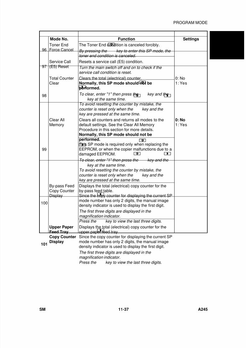
7/18/2019 A219 245 B019 4015 3813 Service
http://slidepdf.com/reader/full/a219-245-b019-4015-3813-service 344/372
Mode No. Function Settings
96Toner EndForce Cancel
The Toner End condition is canceled forcibly.
By pressing the key to enter this SP mode, the toner end condition is canceled.
97Service Call(E5) Reset
Resets a service call (E5) condition.Turn the main switch off and on to check if the service call condition is reset.
98
Total CounterClear
Clears the total (electrical) counter.Normally, this SP mode should not beperformed.
0: No1: Yes
To clear, enter "1" then press the
key and the
key at the same time.To avoid resetting the counter by mistake, the
counter is reset only when the
key and the
key are pressed at the same time.
99
Clear AllMemory Clears all counters and returns all modes to thedefault settings. See the Clear All MemoryProcedure in this section for more details.Normally, this SP mode should not beperformed.This SP mode is required only when replacing theEEPROM, or when the copier malfunctions due to adamaged EEPROM.
0: No1: Yes
To clear, enter "1" then press the
key and the
key at the same time.To avoid resetting the counter by mistake, the
counter is reset only when the
key and the
key are pressed at the same time.
100
By-pass FeedCopy CounterDisplay
Displays the total (electrical) copy counter for theby-pass feed table.Since the copy counter for displaying the current SPmode number has only 2 digits, the manual imagedensity indicator is used to display the first digit.The first three digits are displayed in the magnification indicator.
Press the
key to view the last three digits.
101
Upper PaperFeed TrayCopy Counter
Display
Displays the total (electrical) copy counter for theupper paper feed tray.Since the copy counter for displaying the current SP
mode number has only 2 digits, the manual imagedensity indicator is used to display the first digit.The first three digits are displayed in the magnification indicator.
Press the
key to view the last three digits.
A 2 4 5
C O P I E R
PROGRAM MODE
SM 11-37 A245
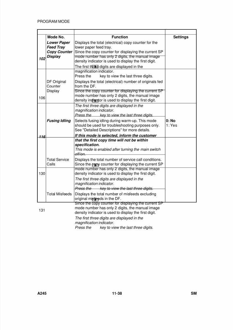
7/18/2019 A219 245 B019 4015 3813 Service
http://slidepdf.com/reader/full/a219-245-b019-4015-3813-service 345/372
Mode No. Function Settings
102
Lower Paper Feed Tray Copy Counter
Display
Displays the total (electrical) copy counter for thelower paper feed tray.Since the copy counter for displaying the current SP
mode number has only 2 digits, the manual imagedensity indicator is used to display the first digit.The first three digits are displayed in themagnification indicator.Press the
key to view the last three digits.
106
DF OriginalCounterDisplay
Displays the total (electrical) number of originals fedfrom the DF.Since the copy counter for displaying the current SPmode number has only 2 digits, the manual imagedensity indicator is used to display the first digit.The first three digits are displayed in the magnification indicator.
Press the key to view the last three digits.
116
Fusing Idling Selects fusing idling during warm-up. This modeshould be used for troubleshooting purposes only.See "Detailed Descriptions" for more details.
0: No1: Yes
If this mode is selected, inform the customer that the first copy time will not be within specification.This mode is enabled after turning the main switch off/on.
130
Total ServiceCalls
Displays the total number of service call conditions.Since the copy counter for displaying the current SPmode number has only 2 digits, the manual imagedensity indicator is used to display the first digit.The first three digits are displayed in the magnification indicator.
Press the
key to view the last three digits.
131
Total Misfeeds Displays the total number of misfeeds excludingoriginal misfeeds in the DF.Since the copy counter for displaying the current SPmode number has only 2 digits, the manual imagedensity indicator is used to display the first digit.The first three digits are displayed in the magnification indicator.
Press the
key to view the last three digits.
PROGRAM MODE
A245 11-38 SM

7/18/2019 A219 245 B019 4015 3813 Service
http://slidepdf.com/reader/full/a219-245-b019-4015-3813-service 346/372
10. PREVENTIVE MAINTENANCE SCHEDULE
10.1 MODIFIED PM TABLE
Below lists the modified PM table for the A219 and A245 copiers.
NOTE: 1) The amounts mentioned as the PM interval indicate the number ofcopies.
2) Refer to "REGULAR PM PROCEDURE" in this section.
Symbol key: L: Lubricate R: Replace C: Clean I: Inspect A: AdjustEM 45 k 90 k 135 k 180 k Notes
Optics
Reflector C C C C Silicone cloth1st to 5th Mirrors C C C C Silicone cloth6th Mirror C C C C Blower brushLens C C C C Blower brushExposure Glass C C C C C Soft cloth dampened with
alcohol or waterPlaten Cover Sheet
C C R C RSoft cloth dampened withwater
Scanner Guide Rod C, L C, L C, L C, L Dry cloth, Grease - CPL501Scanner Guide Rail
C, L C, L C, L C, LDry cloth, Silicone Grease -
G5014th/5th Mirror Guide RodC, L C, L C, L C, L
Dry cloth, Silicone Grease -G501
4th/5th Mirror Guide RailC, L C, L C, L C, L
Dry cloth, Silicone Grease -G501
Blue Filter C C C C Soft clothExposure Lamp/1stScanner Ass’y
Replace at 200 k copies
Around the Drum
Charge Corona Wire C R R R R Blower brush
Transfer Corona Wire C C R C R Blower brushCharge Corona Grid R RTransfer Guide Plate C C C C C Soft clothEnd Blocks and Casings C C C C Blower brush or dry clothCharge Corona CleaningPad
I R R R R
Erase Lamp C C C C C Blower brush or dry clothQL C C C C C Blower brush or dry clothDischarge Plate I C C C C Blower brush
A 2 4 5
C O P I E R
PREVENTIVE MAINTENANCE SCHEDULE
SM 11-39 A245
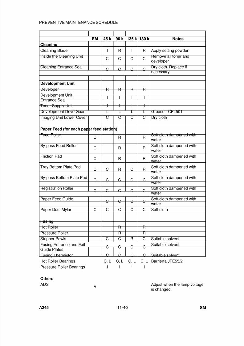
7/18/2019 A219 245 B019 4015 3813 Service
http://slidepdf.com/reader/full/a219-245-b019-4015-3813-service 347/372
EM 45 k 90 k 135 k 180 k Notes
Cleaning
Cleaning Blade I R I R Apply setting powderInside the Cleaning Unit
C C C C
Remove all toner and
developerCleaning Entrance Seal
C C C CDry cloth. Replace ifnecessary
Development Unit
Developer R R R RDevelopment UnitEntrance Seal
I I I I
Toner Supply Unit I I I IDevelopment Drive Gear L L L L Grease - CPL501Imaging Unit Lower Cover C C C C Dry cloth
Paper Feed (for each paper feed station)
Feed RollerC R R
Soft cloth dampened withwater
By-pass Feed RollerC R R
Soft cloth dampened withwater
Friction Pad C R R Soft cloth dampened withwater
Tray Bottom Plate PadC C R C R
Soft cloth dampened withwater
By-pass Bottom Plate PadC C C C C
Soft cloth dampened withwater
Registration RollerC C C C C
Soft cloth dampened withwater
Paper Feed GuideC C C C
Soft cloth dampened withwater
Paper Dust Mylar C C C C C Soft cloth
Fusing
Hot Roller R RPressure Roller R R
Stripper Pawls C C R C Suitable solventFusing Entrance and ExitGuide Plates
C C C CSuitable solvent
Fusing Thermistor C C C C Suitable solventHot Roller Bearings C, L C, L C, L C, L Barrierta JFE55/2Pressure Roller Bearings I I I I
Others
ADSA
Adjust when the lamp voltageis changed.
PREVENTIVE MAINTENANCE SCHEDULE
A245 11-40 SM
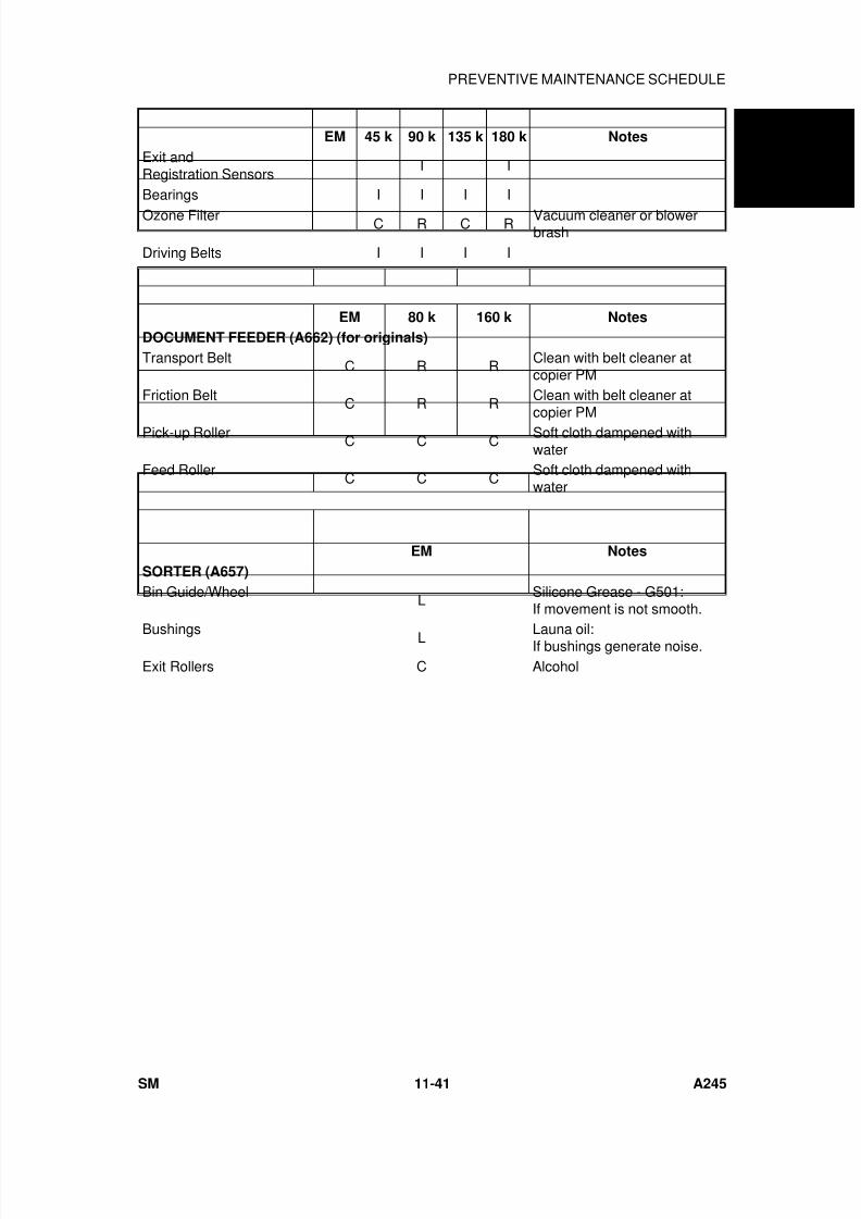
7/18/2019 A219 245 B019 4015 3813 Service
http://slidepdf.com/reader/full/a219-245-b019-4015-3813-service 348/372
EM 45 k 90 k 135 k 180 k Notes
Exit andRegistration Sensors
I I
Bearings I I I I
Ozone Filter C R C R Vacuum cleaner or blowerbrash
Driving Belts I I I I
EM 80 k 160 k Notes
DOCUMENT FEEDER (A662) (for originals)
Transport BeltC R R
Clean with belt cleaner atcopier PM
Friction BeltC R R
Clean with belt cleaner atcopier PM
Pick-up RollerC C C
Soft cloth dampened withwater
Feed RollerC C C
Soft cloth dampened withwater
EM Notes
SORTER (A657)
Bin Guide/WheelL
Silicone Grease - G501:If movement is not smooth.
Bushings L Launa oil:If bushings generate noise.Exit Rollers C Alcohol
A 2 4 5
C O P I E R
PREVENTIVE MAINTENANCE SCHEDULE
SM 11-41 A245
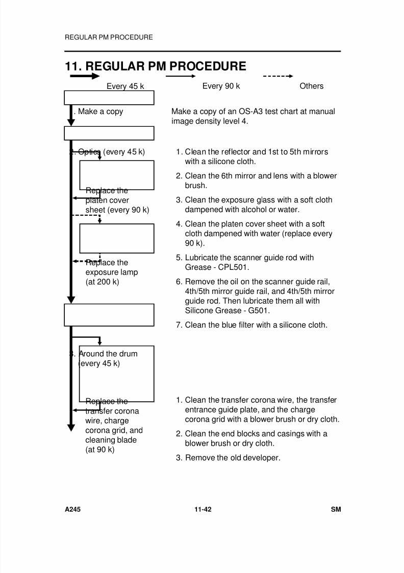
7/18/2019 A219 245 B019 4015 3813 Service
http://slidepdf.com/reader/full/a219-245-b019-4015-3813-service 349/372
11. REGULAR PM PROCEDURE
1. Make a copy Make a copy of an OS-A3 test chart at manualimage density level 4.
2. Optics (every 45 k) 1. Clean the reflector and 1st to 5th mirrorswith a silicone cloth.
2. Clean the 6th mirror and lens with a blowerbrush.
3. Clean the exposure glass with a soft clothdampened with alcohol or water.
4. Clean the platen cover sheet with a softcloth dampened with water (replace every90 k).
5. Lubricate the scanner guide rod withGrease - CPL501.
6. Remove the oil on the scanner guide rail,4th/5th mirror guide rail, and 4th/5th mirror
guide rod. Then lubricate them all withSilicone Grease - G501.
7. Clean the blue filter with a silicone cloth.
3. Around the drum(every 45 k)
1. Clean the transfer corona wire, the transferentrance guide plate, and the chargecorona grid with a blower brush or dry cloth.
2. Clean the end blocks and casings with ablower brush or dry cloth.
3. Remove the old developer.
Replace the
platen coversheet (every 90 k)
Replace theexposure lamp(at 200 k)
Replace thetransfer coronawire, chargecorona grid, andcleaning blade(at 90 k)
Every 45 k Every 90 k Others
REGULAR PM PROCEDURE
A245 11-42 SM
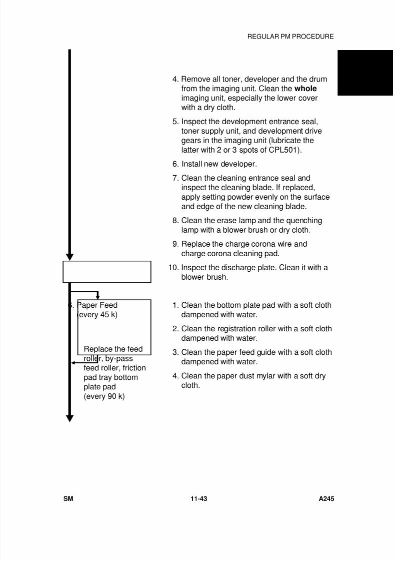
7/18/2019 A219 245 B019 4015 3813 Service
http://slidepdf.com/reader/full/a219-245-b019-4015-3813-service 350/372
4. Remove all toner, developer and the drumfrom the imaging unit. Clean the whole
imaging unit, especially the lower coverwith a dry cloth.
5. Inspect the development entrance seal,toner supply unit, and development drivegears in the imaging unit (lubricate thelatter with 2 or 3 spots of CPL501).
6. Install new developer.
7. Clean the cleaning entrance seal andinspect the cleaning blade. If replaced,
apply setting powder evenly on the surfaceand edge of the new cleaning blade.
8. Clean the erase lamp and the quenchinglamp with a blower brush or dry cloth.
9. Replace the charge corona wire andcharge corona cleaning pad.
10. Inspect the discharge plate. Clean it with ablower brush.
6. Paper Feed(every 45 k)
1. Clean the bottom plate pad with a soft clothdampened with water.
2. Clean the registration roller with a soft clothdampened with water.
3. Clean the paper feed guide with a soft clothdampened with water.
4. Clean the paper dust mylar with a soft drycloth.
Replace the feedroller, by-passfeed roller, frictionpad tray bottom
plate pad(every 90 k)
A 2 4 5
C O P I E R
REGULAR PM PROCEDURE
SM 11-43 A245
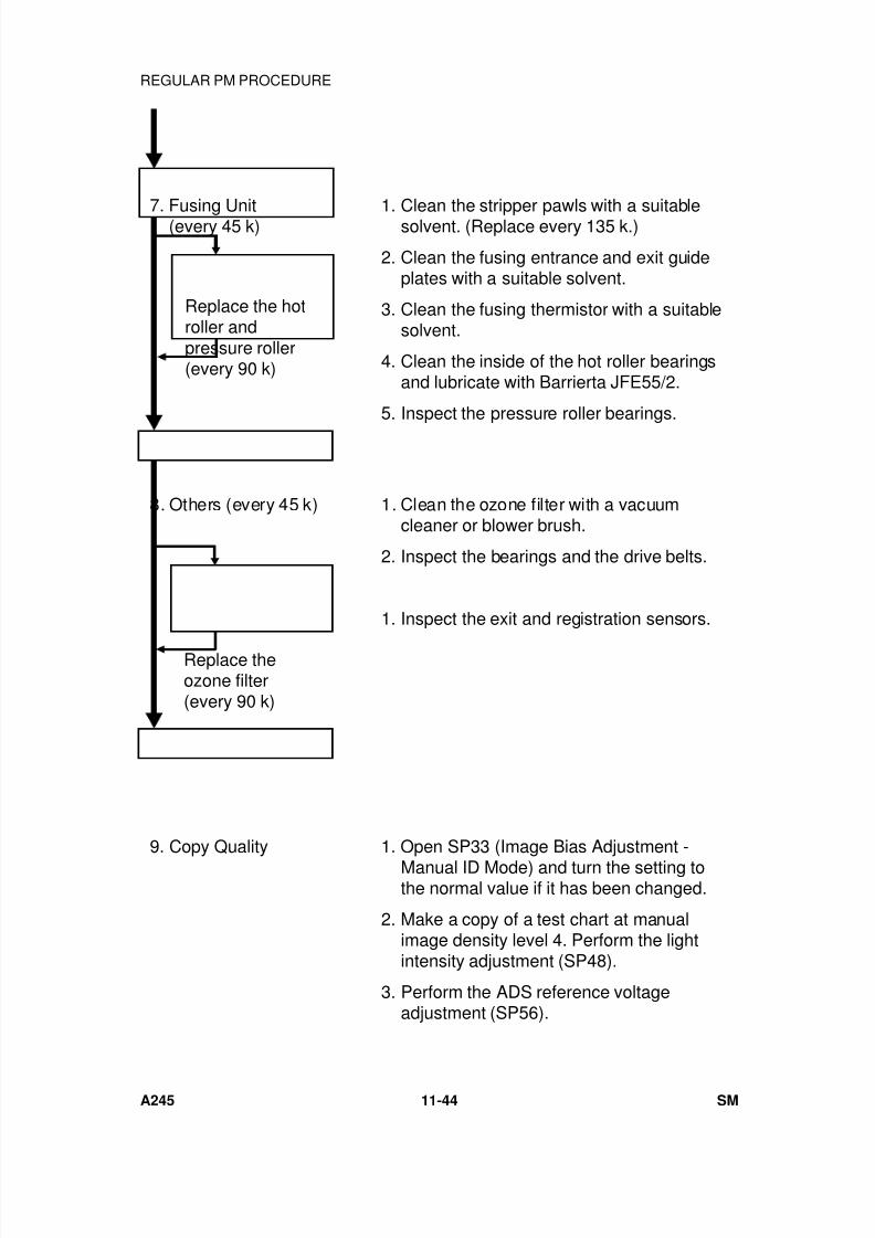
7/18/2019 A219 245 B019 4015 3813 Service
http://slidepdf.com/reader/full/a219-245-b019-4015-3813-service 351/372
7. Fusing Unit(every 45 k) 1. Clean the stripper pawls with a suitablesolvent. (Replace every 135 k.)
2. Clean the fusing entrance and exit guideplates with a suitable solvent.
3. Clean the fusing thermistor with a suitablesolvent.
4. Clean the inside of the hot roller bearingsand lubricate with Barrierta JFE55/2.
5. Inspect the pressure roller bearings.
8. Others (every 45 k) 1. Clean the ozone filter with a vacuumcleaner or blower brush.
2. Inspect the bearings and the drive belts.
1. Inspect the exit and registration sensors.
9. Copy Quality 1. Open SP33 (Image Bias Adjustment -Manual ID Mode) and turn the setting tothe normal value if it has been changed.
2. Make a copy of a test chart at manualimage density level 4. Perform the lightintensity adjustment (SP48).
3. Perform the ADS reference voltageadjustment (SP56).
Replace the hotroller andpressure roller(every 90 k)
Replace theozone filter(every 90 k)
REGULAR PM PROCEDURE
A245 11-44 SM
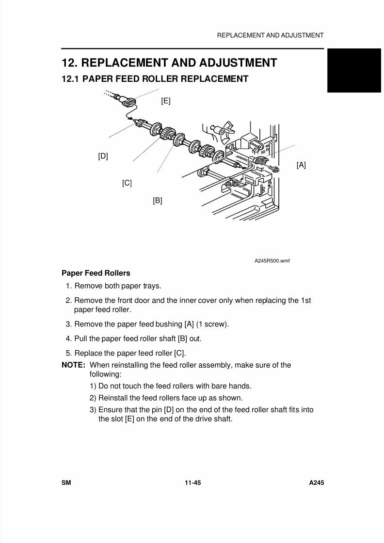
7/18/2019 A219 245 B019 4015 3813 Service
http://slidepdf.com/reader/full/a219-245-b019-4015-3813-service 352/372
12. REPLACEMENT AND ADJUSTMENT
12.1 PAPER FEED ROLLER REPLACEMENT
Paper Feed Rollers
1. Remove both paper trays.
2. Remove the front door and the inner cover only when replacing the 1stpaper feed roller.
3. Remove the paper feed bushing [A] (1 screw).
4. Pull the paper feed roller shaft [B] out.
5. Replace the paper feed roller [C].
NOTE: When reinstalling the feed roller assembly, make sure of the
following:1) Do not touch the feed rollers with bare hands.
2) Reinstall the feed rollers face up as shown.
3) Ensure that the pin [D] on the end of the feed roller shaft fits intothe slot [E] on the end of the drive shaft.
[A]
[C]
[B]
[E]
[D]
A245R500.wmf
A 2 4 5
C O P I E R
REPLACEMENT AND ADJUSTMENT
SM 11-45 A245
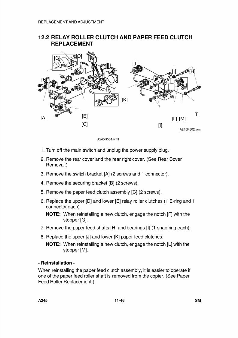
7/18/2019 A219 245 B019 4015 3813 Service
http://slidepdf.com/reader/full/a219-245-b019-4015-3813-service 353/372
12.2 RELAY ROLLER CLUTCH AND PAPER FEED CLUTCHREPLACEMENT
1. Turn off the main switch and unplug the power supply plug.
2. Remove the rear cover and the rear right cover. (See Rear CoverRemoval.)
3. Remove the switch bracket [A] (2 screws and 1 connector). 4. Remove the securing bracket [B] (2 screws).
5. Remove the paper feed clutch assembly [C] (2 screws).
6. Replace the upper [D] and lower [E] relay roller clutches (1 E-ring and 1connector each).
NOTE: When reinstalling a new clutch, engage the notch [F] with thestopper [G].
7. Remove the paper feed shafts [H] and bearings [I] (1 snap ring each).
8. Replace the upper [J] and lower [K] paper feed clutches.NOTE: When reinstalling a new clutch, engage the notch [L] with the
stopper [M].
- Reinstallation -
When reinstalling the paper feed clutch assembly, it is easier to operate ifone of the paper feed roller shaft is removed from the copier. (See PaperFeed Roller Replacement.)
[G][D]
[B][F]
[E][C]
[A]
A245R501.wmf
[J]
[K]
[I]
[I]
[L] [M][I]
[H]
A245R502.wmf
REPLACEMENT AND ADJUSTMENT
A245 11-46 SM
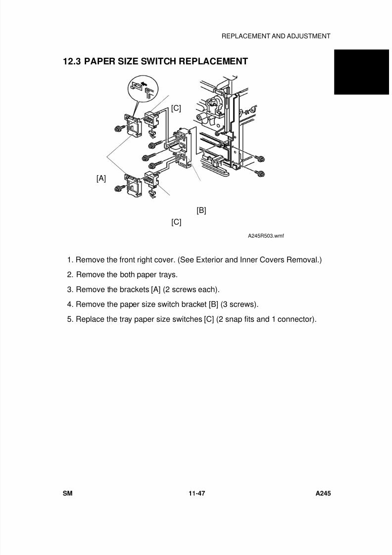
7/18/2019 A219 245 B019 4015 3813 Service
http://slidepdf.com/reader/full/a219-245-b019-4015-3813-service 354/372
12.3 PAPER SIZE SWITCH REPLACEMENT
1. Remove the front right cover. (See Exterior and Inner Covers Removal.)
2. Remove the both paper trays.
3. Remove the brackets [A] (2 screws each). 4. Remove the paper size switch bracket [B] (3 screws).
5. Replace the tray paper size switches [C] (2 snap fits and 1 connector).
[C]
[C]
[B]
[A]
A245R503.wmf
A 2 4 5
C O P I E R
REPLACEMENT AND ADJUSTMENT
SM 11-47 A245
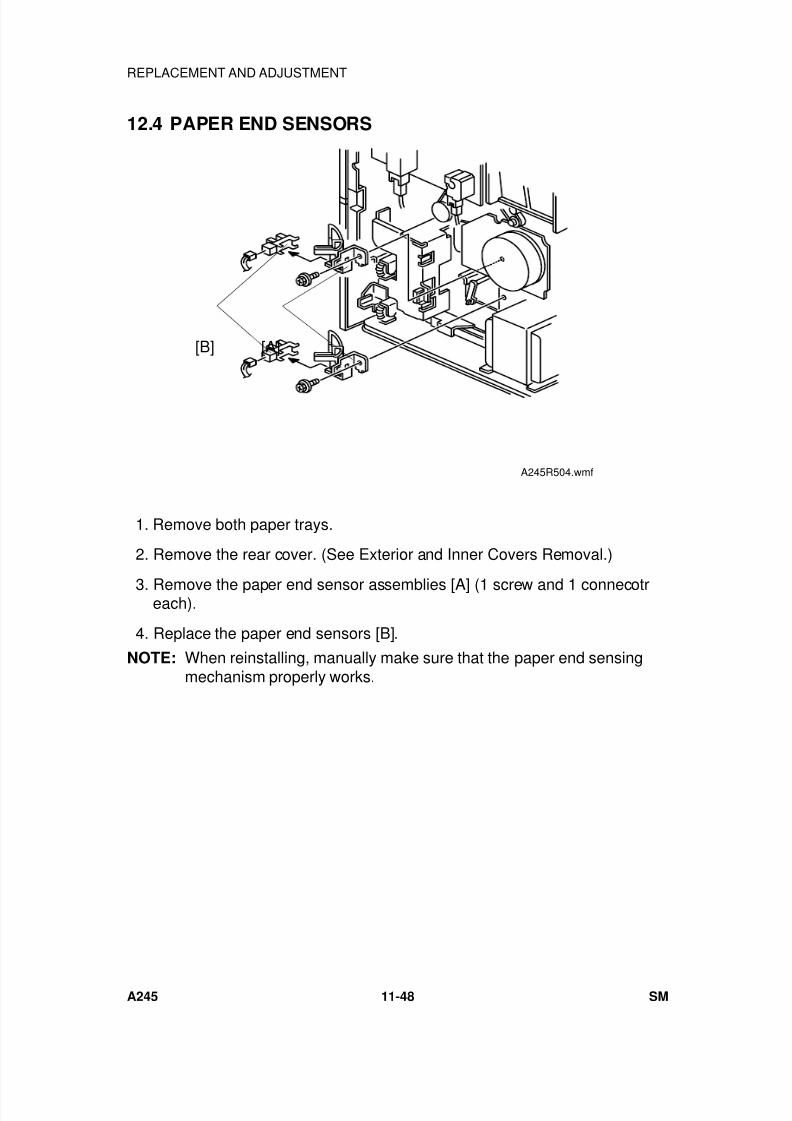
7/18/2019 A219 245 B019 4015 3813 Service
http://slidepdf.com/reader/full/a219-245-b019-4015-3813-service 355/372
12.4 PAPER END SENSORS
1. Remove both paper trays.
2. Remove the rear cover. (See Exterior and Inner Covers Removal.)
3. Remove the paper end sensor assemblies [A] (1 screw and 1 connecotreach).
4. Replace the paper end sensors [B].
NOTE: When reinstalling, manually make sure that the paper end sensingmechanism properly works.
[B] [A]
A245R504.wmf
REPLACEMENT AND ADJUSTMENT
A245 11-48 SM
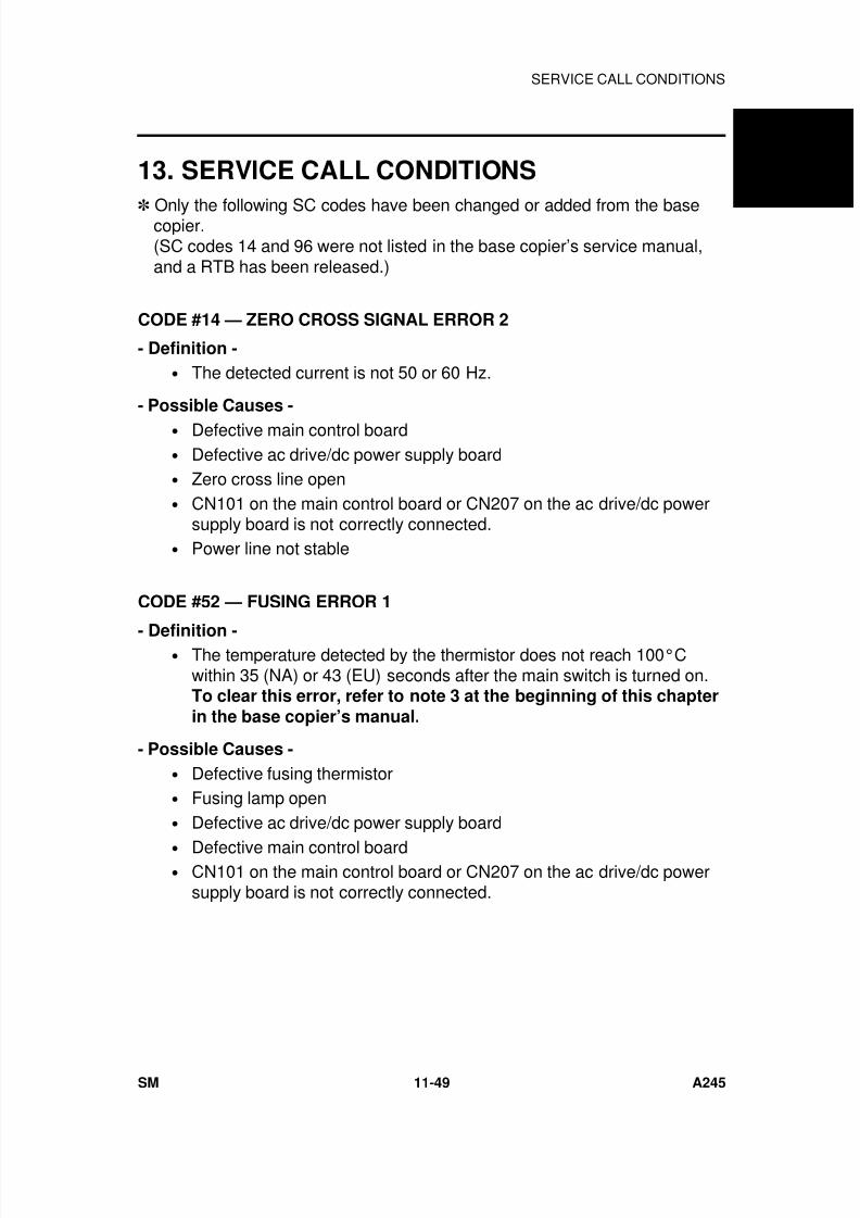
7/18/2019 A219 245 B019 4015 3813 Service
http://slidepdf.com/reader/full/a219-245-b019-4015-3813-service 356/372
13. SERVICE CALL CONDITIONS
Only the following SC codes have been changed or added from the basecopier.(SC codes 14 and 96 were not listed in the base copier’s service manual,and a RTB has been released.)
CODE #14 — ZERO CROSS SIGNAL ERROR 2
- Definition -
• The detected current is not 50 or 60 Hz.
- Possible Causes -
• Defective main control board• Defective ac drive/dc power supply board• Zero cross line open• CN101 on the main control board or CN207 on the ac drive/dc power
supply board is not correctly connected.• Power line not stable
CODE #52 — FUSING ERROR 1
- Definition -• The temperature detected by the thermistor does not reach 100°C
within 35 (NA) or 43 (EU) seconds after the main switch is turned on.To clear this error, refer to note 3 at the beginning of this chapter
in the base copier’s manual.
- Possible Causes -
• Defective fusing thermistor• Fusing lamp open• Defective ac drive/dc power supply board
• Defective main control board• CN101 on the main control board or CN207 on the ac drive/dc power
supply board is not correctly connected.
A 2 4 5
C O P I E R
SERVICE CALL CONDITIONS
SM 11-49 A245
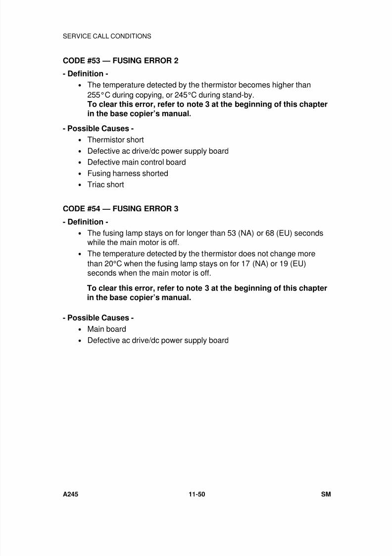
7/18/2019 A219 245 B019 4015 3813 Service
http://slidepdf.com/reader/full/a219-245-b019-4015-3813-service 357/372
CODE #53 — FUSING ERROR 2
- Definition -
• The temperature detected by the thermistor becomes higher than
255°C during copying, or 245°C during stand-by.To clear this error, refer to note 3 at the beginning of this chapterin the base copier’s manual.
- Possible Causes -
• Thermistor short• Defective ac drive/dc power supply board• Defective main control board• Fusing harness shorted• Triac short
CODE #54 — FUSING ERROR 3
- Definition -
• The fusing lamp stays on for longer than 53 (NA) or 68 (EU) secondswhile the main motor is off.
• The temperature detected by the thermistor does not change morethan 20°C when the fusing lamp stays on for 17 (NA) or 19 (EU)seconds when the main motor is off.
- Possible Causes -
• Main board• Defective ac drive/dc power supply board
To clear this error, refer to note 3 at the beginning of this chapterin the base copier’s manual.
SERVICE CALL CONDITIONS
A245 11-50 SM
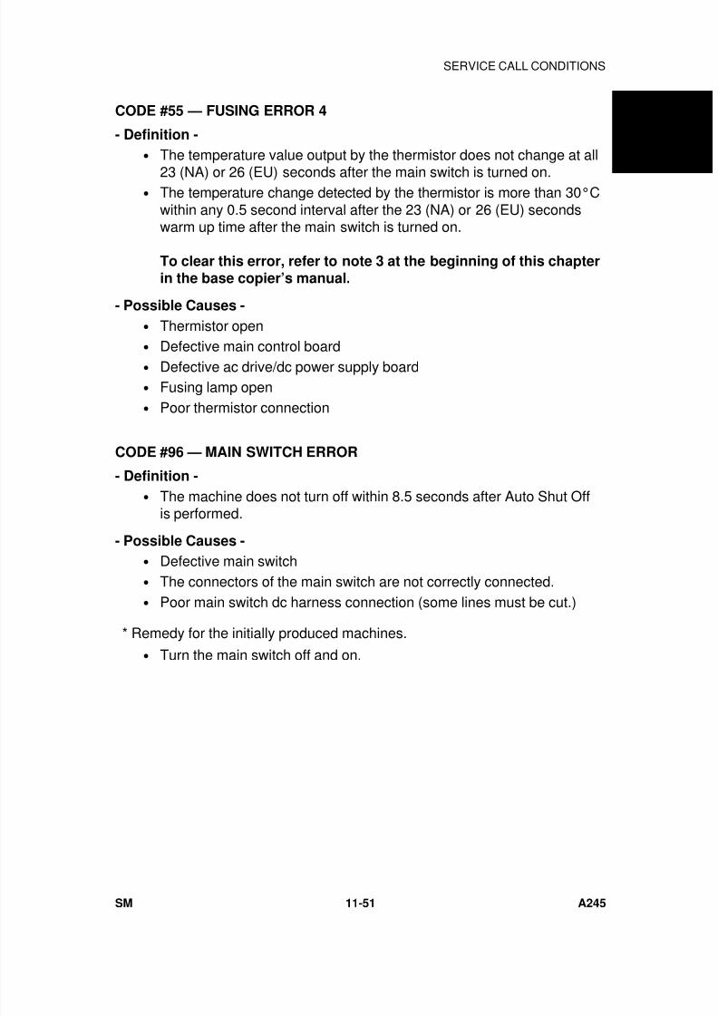
7/18/2019 A219 245 B019 4015 3813 Service
http://slidepdf.com/reader/full/a219-245-b019-4015-3813-service 358/372
CODE #55 — FUSING ERROR 4
- Definition -
• The temperature value output by the thermistor does not change at all
23 (NA) or 26 (EU) seconds after the main switch is turned on.• The temperature change detected by the thermistor is more than 30°C
within any 0.5 second interval after the 23 (NA) or 26 (EU) secondswarm up time after the main switch is turned on.
To clear this error, refer to note 3 at the beginning of this chapterin the base copier’s manual.
- Possible Causes -
• Thermistor open•
Defective main control board• Defective ac drive/dc power supply board• Fusing lamp open• Poor thermistor connection
CODE #96 — MAIN SWITCH ERROR
- Definition -
• The machine does not turn off within 8.5 seconds after Auto Shut Offis performed.
- Possible Causes -
• Defective main switch• The connectors of the main switch are not correctly connected.• Poor main switch dc harness connection (some lines must be cut.)
• Turn the main switch off and on.
* Remedy for the initially produced machines.
A 2 4 5
C O P I E R
SERVICE CALL CONDITIONS
SM 11-51 A245
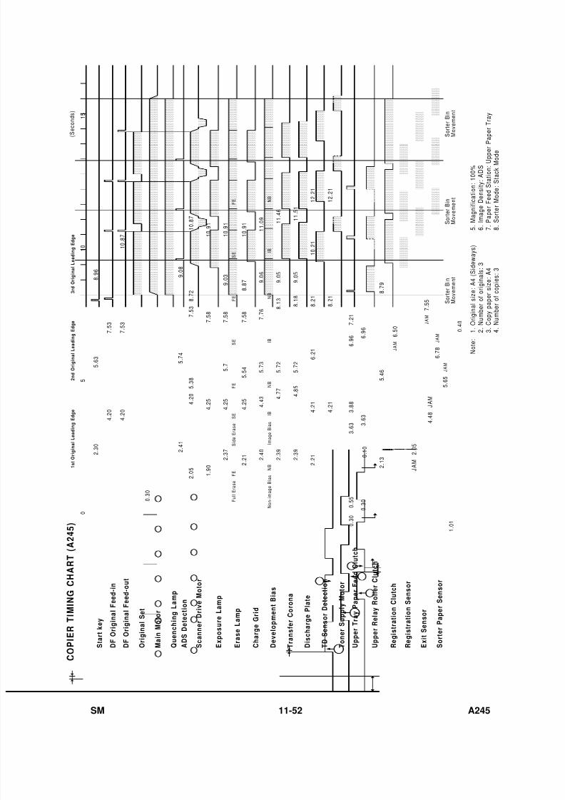
7/18/2019 A219 245 B019 4015 3813 Service
http://slidepdf.com/reader/full/a219-245-b019-4015-3813-service 359/372
N B
I B
N B
I B
N B
I m a g e B i a s
I B
N o n - i m a g e B i a s
N B
F E
S E
F E
S E
F E
S i d e E r a s e
S
E
F u l l E r a s e
F E
2 . 3 0
5 . 6 3
8 . 9 6
4 .
2 0
4 .
2 0
7 . 5 3
7 . 5 3
1 0 . 8 7
2 . 4 1
5 . 7 4
9 . 0 8
4 . 2 0
5 . 3 8
7 . 5 3
8 . 7 2
1 0 . 8 7
2 . 0 5
1 . 9 0
4 . 2 5
7 . 5 8
1 0 . 9 1
2 . 2 1
4 . 2 5
5 . 7
7 . 5 8
9 . 0 3
1 0 . 9 1
4 . 2 5
5 . 5 4
7 . 5 8
8 . 8 7
1 0 . 9 1
2 . 3 7
2 . 4 0
4 . 4 3
5 . 7 3
7 . 7 6
9 . 0 6
1 1 . 0 9
2 . 3 9
4 . 7 7
5 . 7 2
2 . 3 9
4 . 8 5
5 . 7 2
8 . 1 3
9 . 0 5
1 1 . 4 6
9 . 0
5
8 . 1 8
1 1 . 5 1
2 . 2 1
3 . 6 3
3 . 8 8
6 . 9 6
7 . 2 1
S t a r t k e y
D F
O r i g i n a l F e e d - i n
D F
O r i g i n a l F e e d - o u t
O r i g i n a l S e t
M a i n
M o t o r
Q u e n c h i n g
L a m p
A D S
D e t e c t i o n
S c a n n e r D r i v e M o t o r
E x p o s u r e L a m p
D e v e l o p m e n t B i a s
E r a s e L a m p
C h a r g e G r i d
T r a n s f e r C o r o n a
D i s c h a r g e P l a t e
T D
S e n s o r D e t e c t i o n
T o n e r S u p p l y M o t o r
U p p e r T r a y P a p e r F e e d
C l u t c h
U p p e r R e l a y R o l l e r C l u t c h
R e g i s t r a t i o n
C l u t c h
R e g i s t r a t i o n
S e n s o r
E x i t S e n s o r
S o r t e r P a p e r S e n s o r
0
5
1 0
1 5
( S e c o n d s )
1 s t O r i g i n a l L e a d i n g
E d
g e
2 n d
O r i g i n a l L e a d i n g
E d g e
3 r d
O r i g i n a l L e a d i n g
E d g e
C O P I E R
T I M I N G C
H A R T
( A 2 4 5 )
0 . 3 0
0 . 3 0
0 . 5 5
0 . 1 0
2 . 1 3
5 . 4 6
8 . 7 9
1 . 0 1
N o t e :
1 . O r i g i n a l s i z e : A 4
( S i d e w a y s )
2 . N u m b e r o f o r i g i n a l s : 3
3 . C o p y p a p e r s i z e :
A 4
4 . N u m b e r o f c o p i e s
: 3
5 . M a g n i f i c a t i o n : 1 0 0 %
6 . I m a g e D e n s i t y : A D S
7 . P a p e r F e e d S t a t i o n : U p p e r P a
p e r T r a y
8 . S o r t e r M o d e : S t a c k M o d e
J A M
2 . 0 5
4 . 4
8
5 . 6 5
6 . 5 0
J A M
J A M
6 . 7 8
7 . 5 5
0 . 4 0
S o r t e r B i n
M o v e m e n t
S o r t e r B i n
M o v e m e n t
S o r t e r B i n
M o v e m e n t
4 . 2 1
6 . 2 1
8 . 2 1
1 0 . 2 1
1 2 . 2 1
J A M
J A M
J A M
4 . 2 1
8 . 2 1
1 2 . 2 1
3 . 6 3
6 . 9 6
0 . 3 0
SM 11-52 A245
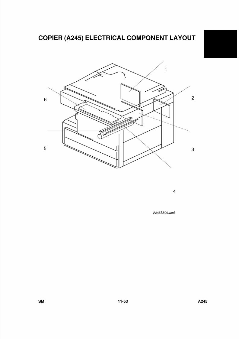
7/18/2019 A219 245 B019 4015 3813 Service
http://slidepdf.com/reader/full/a219-245-b019-4015-3813-service 360/372
COPIER (A245) ELECTRICAL COMPONENT LAYOUT
4
2
3
1
5
6
A245S500.wmf
A 2 4 5
C O P I E R
SM 11-53 A245
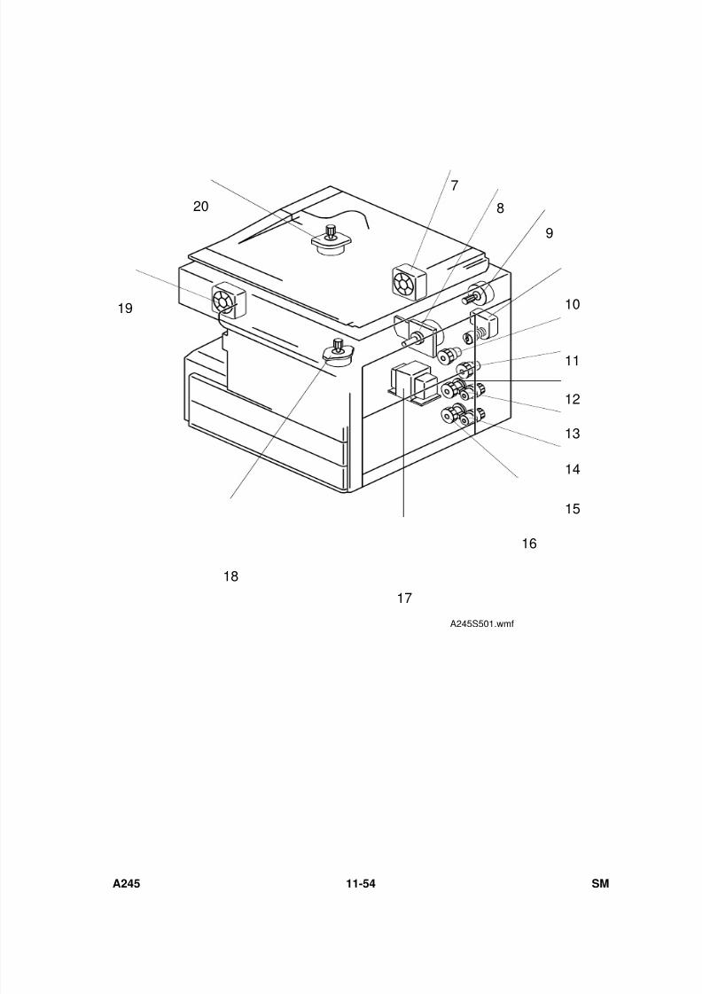
7/18/2019 A219 245 B019 4015 3813 Service
http://slidepdf.com/reader/full/a219-245-b019-4015-3813-service 361/372
10
17
14
13
12
11
9
8
7
20
19
18
16
15
A245S501.wmf
A245 11-54 SM
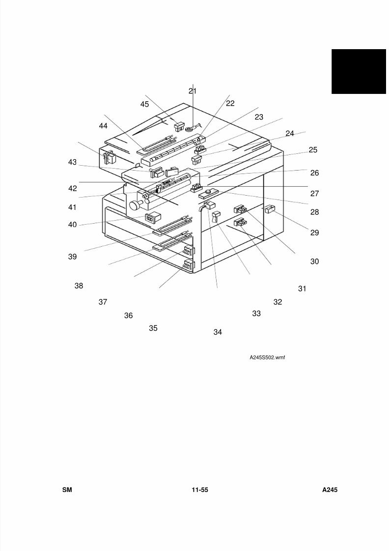
7/18/2019 A219 245 B019 4015 3813 Service
http://slidepdf.com/reader/full/a219-245-b019-4015-3813-service 362/372
26
45
25
31
29
28
27
21
22
23
24
33
44
35
36
38
39
40
41
43
42
34
32
30
37
A245S502.wmf
A 2 4 5
C O P I E R
SM 11-55 A245
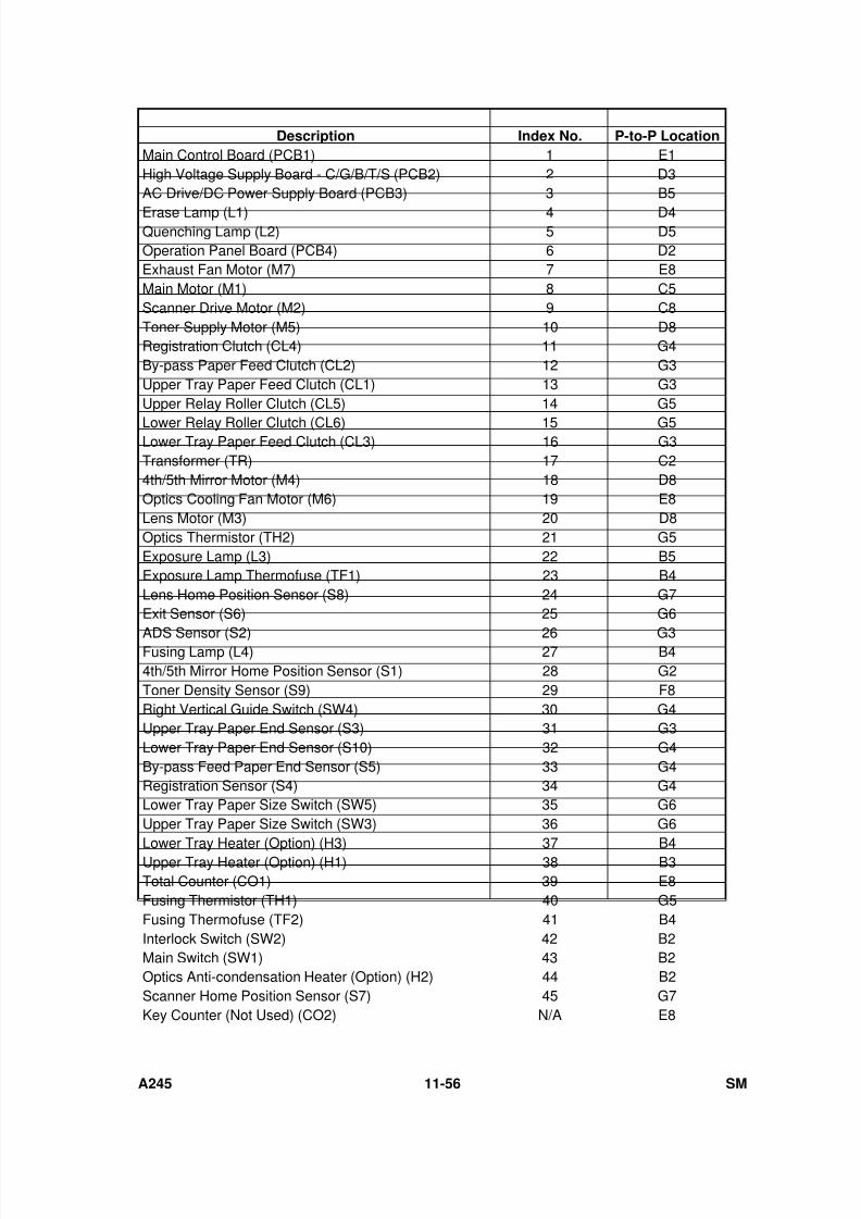
7/18/2019 A219 245 B019 4015 3813 Service
http://slidepdf.com/reader/full/a219-245-b019-4015-3813-service 363/372
Description Index No. P-to-P Location
Main Control Board (PCB1) 1 E1High Voltage Supply Board - C/G/B/T/S (PCB2) 2 D3AC Drive/DC Power Supply Board (PCB3) 3 B5
Erase Lamp (L1) 4 D4Quenching Lamp (L2) 5 D5Operation Panel Board (PCB4) 6 D2Exhaust Fan Motor (M7) 7 E8Main Motor (M1) 8 C5Scanner Drive Motor (M2) 9 C8Toner Supply Motor (M5) 10 D8Registration Clutch (CL4) 11 G4By-pass Paper Feed Clutch (CL2) 12 G3Upper Tray Paper Feed Clutch (CL1) 13 G3Upper Relay Roller Clutch (CL5) 14 G5
Lower Relay Roller Clutch (CL6) 15 G5Lower Tray Paper Feed Clutch (CL3) 16 G3Transformer (TR) 17 C24th/5th Mirror Motor (M4) 18 D8Optics Cooling Fan Motor (M6) 19 E8Lens Motor (M3) 20 D8Optics Thermistor (TH2) 21 G5Exposure Lamp (L3) 22 B5Exposure Lamp Thermofuse (TF1) 23 B4Lens Home Position Sensor (S8) 24 G7Exit Sensor (S6) 25 G6
ADS Sensor (S2) 26 G3Fusing Lamp (L4) 27 B44th/5th Mirror Home Position Sensor (S1) 28 G2Toner Density Sensor (S9) 29 F8Right Vertical Guide Switch (SW4) 30 G4Upper Tray Paper End Sensor (S3) 31 G3Lower Tray Paper End Sensor (S10) 32 G4By-pass Feed Paper End Sensor (S5) 33 G4Registration Sensor (S4) 34 G4Lower Tray Paper Size Switch (SW5) 35 G6Upper Tray Paper Size Switch (SW3) 36 G6
Lower Tray Heater (Option) (H3) 37 B4Upper Tray Heater (Option) (H1) 38 B3Total Counter (CO1) 39 E8Fusing Thermistor (TH1) 40 G5Fusing Thermofuse (TF2) 41 B4Interlock Switch (SW2) 42 B2Main Switch (SW1) 43 B2Optics Anti-condensation Heater (Option) (H2) 44 B2Scanner Home Position Sensor (S7) 45 G7Key Counter (Not Used) (CO2) N/A E8
A245 11-56 SM
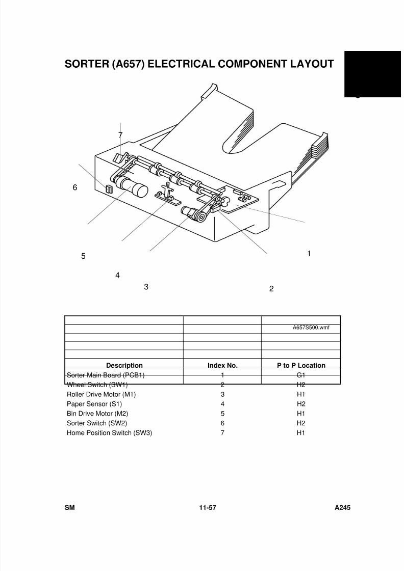
7/18/2019 A219 245 B019 4015 3813 Service
http://slidepdf.com/reader/full/a219-245-b019-4015-3813-service 364/372
SORTER (A657) ELECTRICAL COMPONENT LAYOUT
Description Index No. P to P Location
Sorter Main Board (PCB1) 1 G1Wheel Switch (SW1) 2 H2
Roller Drive Motor (M1) 3 H1Paper Sensor (S1) 4 H2Bin Drive Motor (M2) 5 H1Sorter Switch (SW2) 6 H2Home Position Switch (SW3) 7 H1
1
2
5
43
6
7
A657S500.wmf
A 2 4 5
C O P I E R
SM 11-57 A245
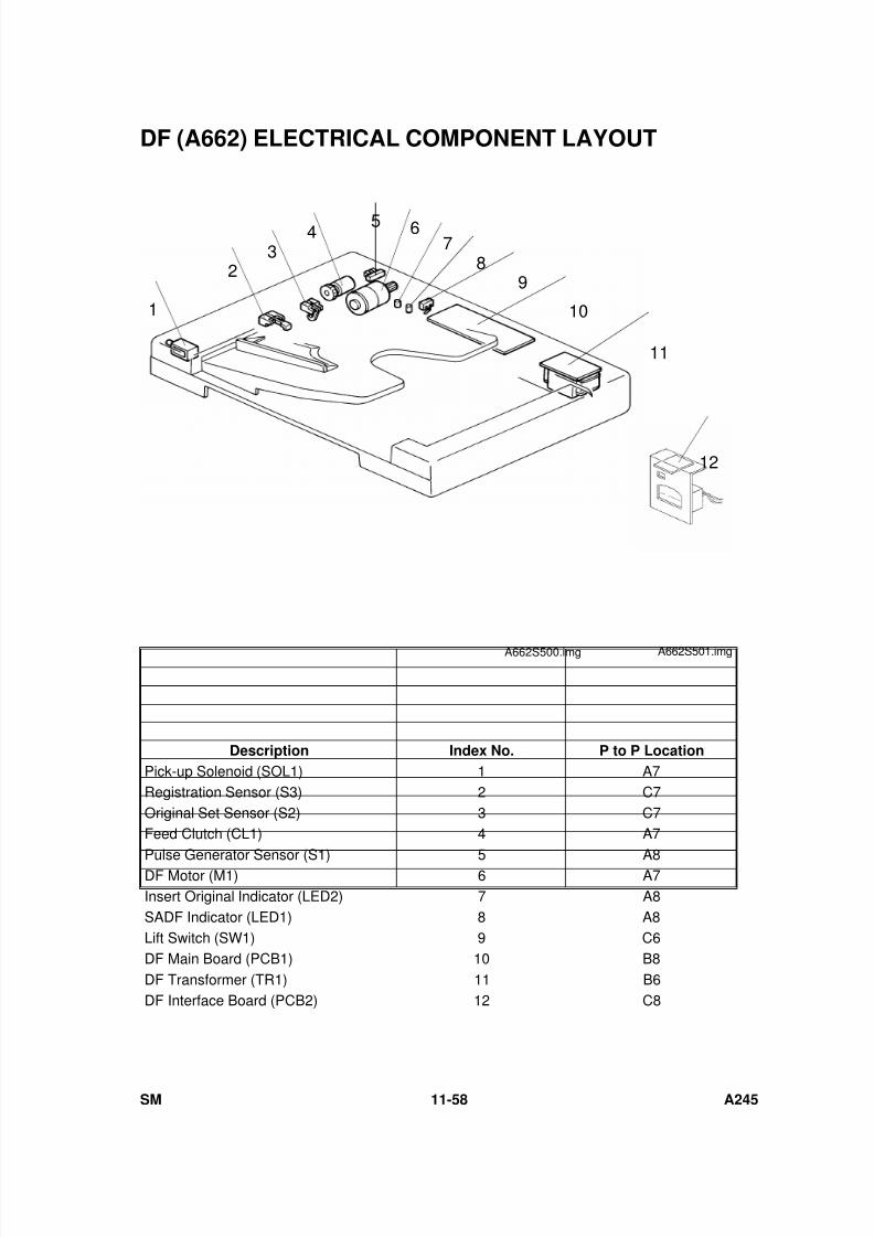
7/18/2019 A219 245 B019 4015 3813 Service
http://slidepdf.com/reader/full/a219-245-b019-4015-3813-service 365/372
DF (A662) ELECTRICAL COMPONENT LAYOUT
Description Index No. P to P Location
Pick-up Solenoid (SOL1) 1 A7Registration Sensor (S3) 2 C7Original Set Sensor (S2) 3 C7Feed Clutch (CL1) 4 A7
Pulse Generator Sensor (S1) 5 A8DF Motor (M1) 6 A7Insert Original Indicator (LED2) 7 A8SADF Indicator (LED1) 8 A8Lift Switch (SW1) 9 C6DF Main Board (PCB1) 10 B8DF Transformer (TR1) 11 B6DF Interface Board (PCB2) 12 C8
1
98
7654
32
10
11
A662S500.img
12
A662S501.img
SM 11-58 A245
7/18/2019 A219 245 B019 4015 3813 Service
http://slidepdf.com/reader/full/a219-245-b019-4015-3813-service 366/372
B019
SERVICE MANUAL

7/18/2019 A219 245 B019 4015 3813 Service
http://slidepdf.com/reader/full/a219-245-b019-4015-3813-service 367/372
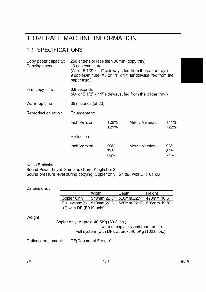
7/18/2019 A219 245 B019 4015 3813 Service
http://slidepdf.com/reader/full/a219-245-b019-4015-3813-service 368/372
SM 12-1 B019
B 0 1 9
1. OVERALL MACHINE INFORMATION
1.1 SPECIFICATIONS
Copy paper capacity: 250 sheets or less than 30mm (copy tray)Copying speed: 13 copies/minute (A4 or 8 1/2” x 11” sideways, fed from the paper tray.) 9 copies/minute (A3 or 11” x 17” lengthwise, fed from the paper tray.)
First copy time : 6.9 seconds (A4 or 8 1/2” x 11” sideways, fed from the paper tray.)
Warm-up time : 35 seconds (at 23)
Reproduction ratio : Enlargement:
Inch Version: 129% Metric Version: 141% 121% 122%
Reduction:
Inch Version: 93% Metric Version: 93%
74% 82%65% 71%
Noise Emission:Sound Power Level: Same as Grand Kingfisher 2Sound pressure level during copying: Copier only: 57 dB, with DF: 61 dB
Dimensions :
Width Depth Height
Copier Only 579mm,22.8” 560mm,22.1” 420mm,16.6”
Full system(*) 579mm,22.8” 560mm,22.1” 508mm,19.8”(*) with DF (B019 only)
Weight :Copier only: Approx. 40.5Kg (89.3 lbs.)
*without copy tray and toner bottle.Full system (with DF): approx. 46.5Kg (102.6 lbs.)
Optional equipment: DF(Document Feeder)
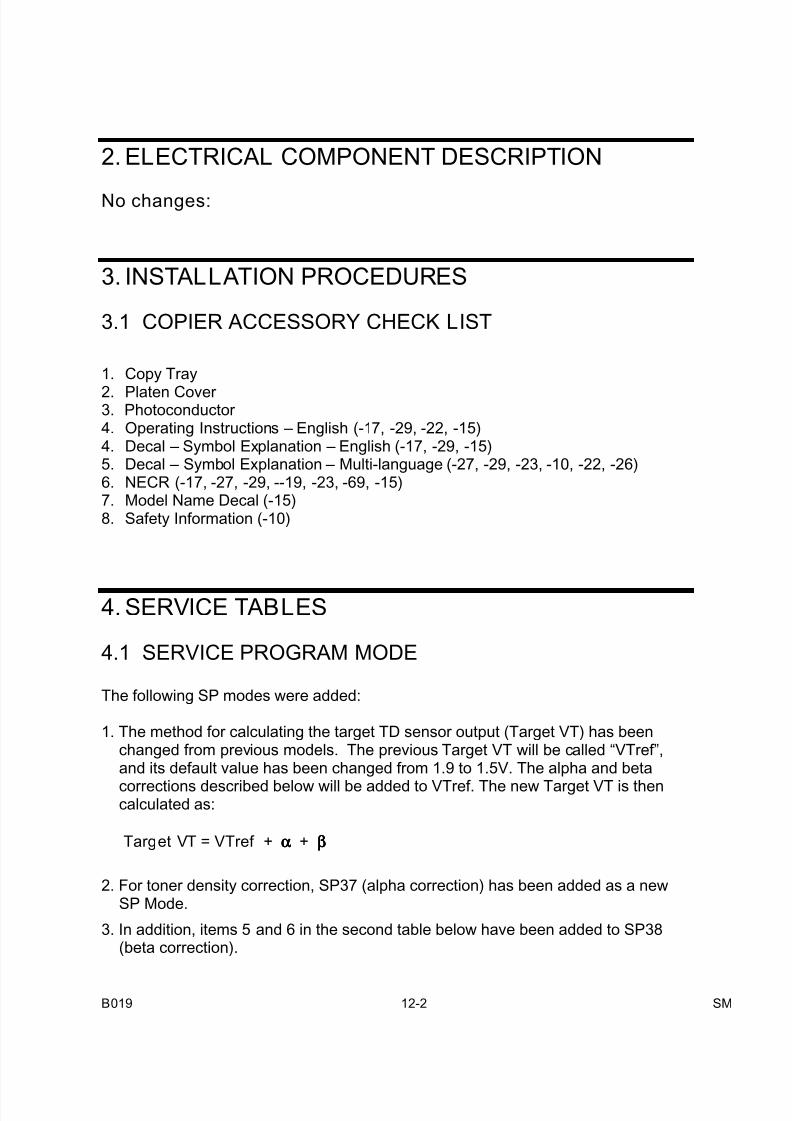
7/18/2019 A219 245 B019 4015 3813 Service
http://slidepdf.com/reader/full/a219-245-b019-4015-3813-service 369/372
B019 12-2 SM
2. ELECTRICAL COMPONENT DESCRIPTION
No changes:
3. INSTALLATION PROCEDURES
3.1 COPIER ACCESSORY CHECK LIST
1. Copy Tray
2. Platen Cover 3. Photoconductor 4. Operating Instructions – English (-17, -29, -22, -15)4. Decal – Symbol Explanation – English (-17, -29, -15)5. Decal – Symbol Explanation – Multi-language (-27, -29, -23, -10, -22, -26)6. NECR (-17, -27, -29, --19, -23, -69, -15)7. Model Name Decal (-15)8. Safety Information (-10)
4. SERVICE TABLES
4.1 SERVICE PROGRAM MODE
The following SP modes were added:
1. The method for calculating the target TD sensor output (Target VT) has beenchanged from previous models. The previous Target VT will be called “VTref”,and its default value has been changed from 1.9 to 1.5V. The alpha and betacorrections described below will be added to VTref. The new Target VT is thencalculated as:
Target VT = VTref + αααα + ββββ
2. For toner density correction, SP37 (alpha correction) has been added as a newSP Mode.
3. In addition, items 5 and 6 in the second table below have been added to SP38(beta correction).
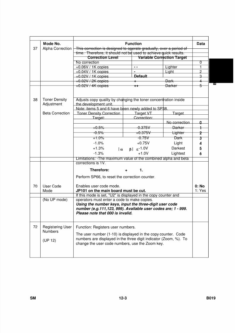
7/18/2019 A219 245 B019 4015 3813 Service
http://slidepdf.com/reader/full/a219-245-b019-4015-3813-service 370/372
SM 12-3 B019
B 0 1 9
Mode No. Function Data
This correction is designed to operate gradually, over a period oftime. Therefore, it should not be used to achieve quick results.
Correction Level Variable Correction TargetNo correction 0+0.06V / 1K copies - - Lighter 1+0.04V / 1K copies - Light 2+0.02V / 1K copies Default 3+0.02V / 2K copies + Dark 4+0.02V / 4K copies ++ Darker 5
37 Alpha Correction
Adjusts copy quality by changing the toner concentration insidethe development unit.Note: items 5 and 6 have been newly added to SP38.Toner Density Correction
Target:Target VTCorrection:
Target
No correction 0
+0.5% -0.375V Darker 1
-0.5% +0.375V Lighter 2
+1.0% -0.75V Dark 3
-1.0% +0.75V Light 4
+1.3% -1.0V Darkest 5
-1.3% +1.0V Lightest 6
38 Toner DensityAdjustment
Beta Correction
Limitations: -The maximum value of the combined alpha and betacorrections is 1V.
Therefore: + β ≤ 1.
Perform SP66, to reset the correction counter.
70 User CodeMode
(No UP mode)
Enables user code mode.JP101 on the main board must be cut.If this mode is set, "U2" is displayed in the copy counter andoperators must enter a code to make copies.Using the number keys, input the three-digit user code number (e.g.111,123, 999). Available user codes are; 1 - 999.Please note that 000 is invalid.
0: No1: Yes
72 Registering User
Numbers
(UP 12)
Function: Registers user numbers.
The user number (1-10) is displayed in the copy counter. Codenumbers are displayed in the three digit indicator (Zoom, %). Tochange the user code numbers, use the Zoom key.
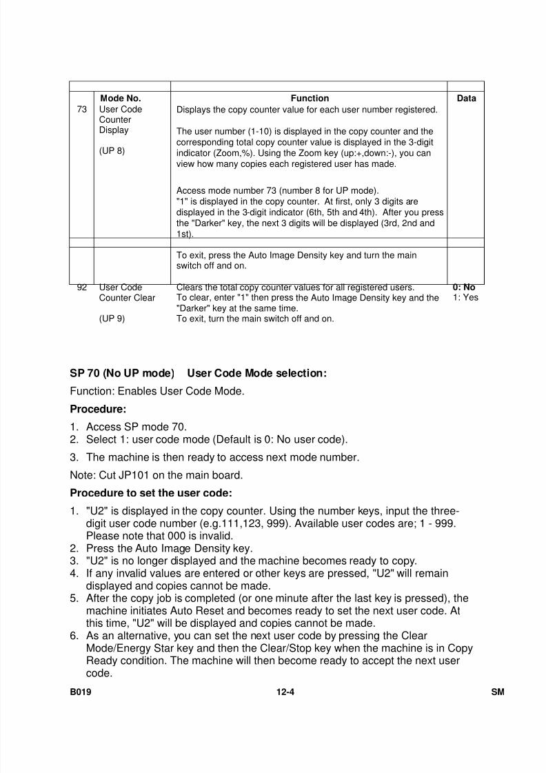
7/18/2019 A219 245 B019 4015 3813 Service
http://slidepdf.com/reader/full/a219-245-b019-4015-3813-service 371/372
B019 12-4 SM
Mode No. Function Data
73 User CodeCounter
Display
(UP 8)
Displays the copy counter value for each user number registered.
The user number (1-10) is displayed in the copy counter and thecorresponding total copy counter value is displayed in the 3-digitindicator (Zoom,%). Using the Zoom key (up:+,down:-), you canview how many copies each registered user has made.
Access mode number 73 (number 8 for UP mode)."1" is displayed in the copy counter. At first, only 3 digits aredisplayed in the 3-digit indicator (6th, 5th and 4th). After you pressthe "Darker" key, the next 3 digits will be displayed (3rd, 2nd and1st).
To exit, press the Auto Image Density key and turn the main
switch off and on.
92 User CodeCounter Clear
(UP 9)
Clears the total copy counter values for all registered users.To clear, enter "1" then press the Auto Image Density key and the"Darker" key at the same time.To exit, turn the main switch off and on.
0: No1: Yes
SP 70 (No UP mode) User Code Mode selection:
Function: Enables User Code Mode.
Procedure:
1. Access SP mode 70.2. Select 1: user code mode (Default is 0: No user code).
3. The machine is then ready to access next mode number.
Note: Cut JP101 on the main board.
Procedure to set the user code:
1. "U2" is displayed in the copy counter. Using the number keys, input the three-digit user code number (e.g.111,123, 999). Available user codes are; 1 - 999.
Please note that 000 is invalid.2. Press the Auto Image Density key.3. "U2" is no longer displayed and the machine becomes ready to copy.4. If any invalid values are entered or other keys are pressed, "U2" will remain
displayed and copies cannot be made.5. After the copy job is completed (or one minute after the last key is pressed), the
machine initiates Auto Reset and becomes ready to set the next user code. Atthis time, "U2" will be displayed and copies cannot be made.
6. As an alternative, you can set the next user code by pressing the ClearMode/Energy Star key and then the Clear/Stop key when the machine is in CopyReady condition. The machine will then become ready to accept the next user
code.
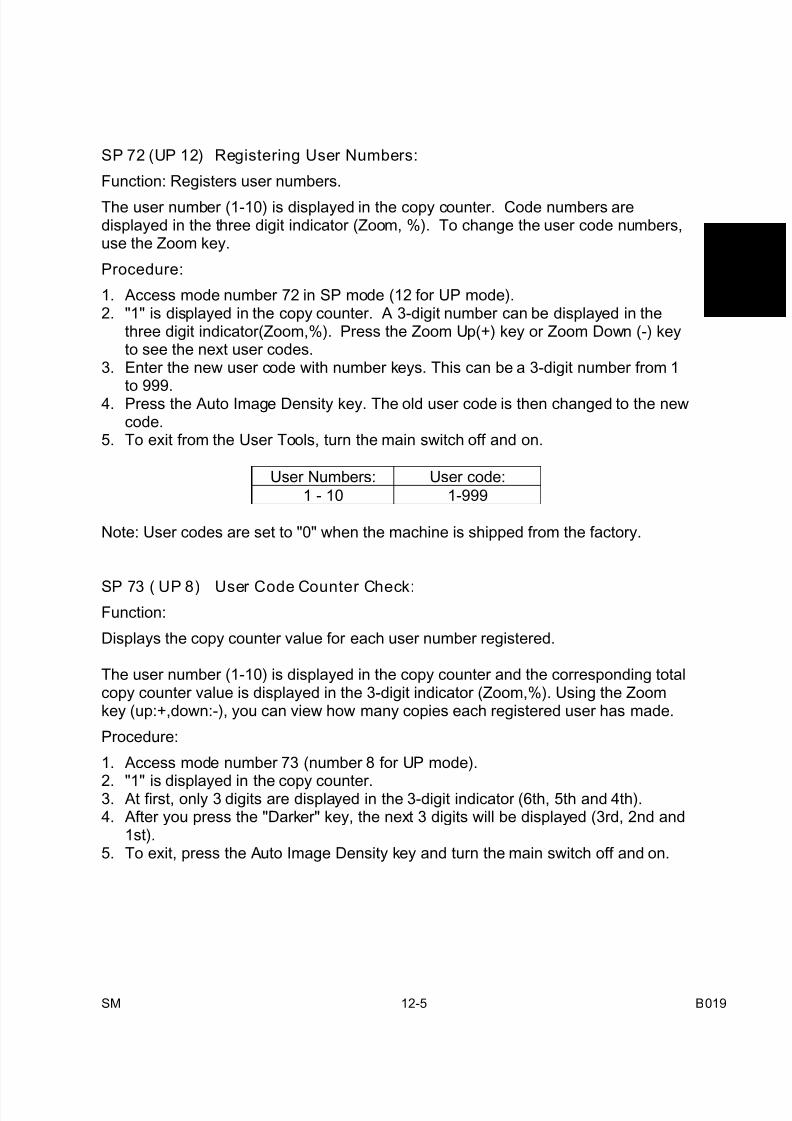
7/18/2019 A219 245 B019 4015 3813 Service
http://slidepdf.com/reader/full/a219-245-b019-4015-3813-service 372/372
B 0 1 9
SP 72 (UP 12) Registering User Numbers:
Function: Registers user numbers.
The user number (1-10) is displayed in the copy counter. Code numbers aredisplayed in the three digit indicator (Zoom, %). To change the user code numbers,use the Zoom key.
Procedure:
1. Access mode number 72 in SP mode (12 for UP mode).2. "1" is displayed in the copy counter. A 3-digit number can be displayed in the
three digit indicator(Zoom,%). Press the Zoom Up(+) key or Zoom Down (-) keyto see the next user codes.
3. Enter the new user code with number keys. This can be a 3-digit number from 1
to 999.4. Press the Auto Image Density key. The old user code is then changed to the new
code.5. To exit from the User Tools, turn the main switch off and on.
User Numbers: User code:
1 - 10 1-999
Note: User codes are set to "0" when the machine is shipped from the factory.
SP 73 ( UP 8) User Code Counter Check:
Function:
Displays the copy counter value for each user number registered.
The user number (1-10) is displayed in the copy counter and the corresponding totalcopy counter value is displayed in the 3-digit indicator (Zoom,%). Using the Zoomkey (up:+,down:-), you can view how many copies each registered user has made.
Procedure:
1. Access mode number 73 (number 8 for UP mode).
2. "1" is displayed in the copy counter.3. At first, only 3 digits are displayed in the 3-digit indicator (6th, 5th and 4th).4. After you press the "Darker" key, the next 3 digits will be displayed (3rd, 2nd and
1st).5. To exit, press the Auto Image Density key and turn the main switch off and on.
![CZ-3813 English Datasheet[CZ-3813] 018010460-E-00 2018/10 - 1 - CZ 1. General Description CZ-3813 is an open-type current sensor using Hall sensors, which outputs the analog voltage](https://img.pdfslide.us/doc/110x75/5e6e25e105260251bd5cda55/cz-3813-english-datasheet-cz-3813-018010460-e-00-201810-1-cz-1-general-description.jpg)


![AD-A219 576 Estimate Occupation -Specific Bonus Effects · Lakhani and Gilroy [1984] all observe considerable differences among groups of specialties in the responsiveness to bonuses](https://img.pdfslide.us/doc/110x75/5e00e070a3176c21915f34b6/ad-a219-576-estimate-occupation-specific-bonus-effects-lakhani-and-gilroy-1984.jpg)