Embed Size (px)
Citation preview
A200SP Circle Absorber
User Manual
Partnership for Life

IMPORTANT
Servicing and Repairs
In order to ensure the full operational life of this
device, servicing by an engineer trained by the
manufacturer should be undertaken periodically.
We recommend that the absorber should be
serviced on the following schedule:
(a) Six monthly inspection and function
testing.
(b) Annual service which includes routine
replacement of seals etc, as preventive
maintenance.
Details of these operations are in the A200SP
Circle Absorber service manual, which contains
servicing procedures etc. Servicing should be
carried out by engineers trained by Penlon Ltd.
For any enquiry regarding the servicing or repair
of this device, contact the nearest accredited
Penlon agent:
or communicate directly with:
Technical Support Department
Penlon Limited
Abingdon
OX14 3PH
UK
Tel: 44 (0) 1235 547076
Fax: 44 (0) 1235 547062
E-mail: [email protected]
Always give as much of the following
information as possible:
1. Type of equipment
2. Product name
3. Serial number
4. Approximate date of purchase
5. Apparent fault
(i)
FOREWORD
This manual has been produced to provide
authorised personnel with information on the
function, routine, performance and maintenance
checks applicable to the A200SP Absorber.
Information contained in this manual is correct at
the date of publication. The policy of the
manufacturer is one of continued improvement to
their products. Because of this policy the
manufacturer reserves the right to make any
changes which may affect instructions in this
manual, without giving prior notice.
Personnel must make themselves familiar
with the contents of this manual and the
machine function before using the apparatus.
Copyright © Penlon Ltd 2009
All rights reserved.
(ii)
IMPORTANCE OF PATIENT MONITORING
WARNINGAnaesthesia systems have the capability todeliver mixtures of gases and vapours to thepatient which could cause injury or death unlesscontrolled by a qualified anaesthetist.
There can be considerable variation in the effectof anaesthetic drugs on individual patients sothat the setting and observation of control levelson the anaesthesia system does not in itselfensure total patient safety.Anaesthesia system monitors and patientmonitors are very desirable aids for theanaesthetist but are not true clinical monitors as the condition of the patient is alsodependent on his respiration and the functioningof his cardio-vascular system.
IT IS ESSENTIAL THAT THESE ELEMENTS AREMONITORED FREQUENTLY AND REGULARLYAND THAT ANY OBSERVATIONS ARE GIVENPRECEDENCE OVER MACHINE CONTROLPARAMETERS IN JUDGING THE STATE OF ACLINICAL PROCEDURE.
Before using any monitoring system or
device, the user must check that it conforms
to the relevant standard, as listed in the table
below.
Parameter / Device Relevant Standard
Pressure Measuring ISO 8835-2
Pressure Limitation Device EN 60601-2-13:2006 - 51.101.1
Exhaled Volume Monitor EN 60601-2-13:2006 - 51.101.4
Breathing System Integrity Alarm System EN 60601-2-13:2006 - 51.101.5
Continuing Pressure Alarm EN 60601-2-13:2006 - 51.101.6
Oxygen Monitor ISO 7767
Carbon Dioxide Monitor ISO 9918
Breathing Circuit ISO 8835-2
Agent Monitor ISO 11196
Gas Scavenging ISO 8835-3
For information on installing and connection of any of these systems or devices, please refer to the relevant manufacturer’s instructions.
CONTENTS
Page No.
USER RESPONSIBILITY 1
1. WARNINGS AND CAUTIONS 2
2. PURPOSE 4
3. DESCRIPTION
3.1 Canisters 6
3.2 Inspiratory and Expiratory Non-return Valves (NRV) 6
3.3 Bag/Ventilator Switch 6
3.4 Adjustable Pressure Limiting (APL) Valve 7
3.5 Fresh Gas Inlet and Tubing 7
3.6 Manometer 8
3.7 Heater (option) 8
3.8 Bypass Flow 8
3.9 End Tidal Carbon Dioxide Monitoring 8
3.10 Interface to AV-S Ventilator 9
3.11 Gas Flow Diagrams 10
4. SPECIFICATION
4.1 General Dimensions and Weight 11
4.2 Resistance of Breathing System 11
4.2.1 Expiratory Resistance 11
4.2.2 Inspiratory Resistance 11
4.3 Internal Compressible Volume 11
4.4 System Leakage Rate 12
4.5 Canister Capacity and Resistance 12
4.5.1 Canister Capacity 12
4.5.2 Canister Resistance 12
4.6 Non-return valves 12
4.7 Mode of Operation 12
4.8 Heater (option) 13
4.9 Device Classification and Labelling 13
4.10 Environmental 13
5. INSTALLATION AND OPERATION
5.1 Mounting the Absorber 14
5.2 System Connections 15
5.3 Changing CO2 Absorbent 17
5.4 Manometer 18
5.5 Heater (option) 18
6. PRE-USE CHECKS
6.1 Pre-use Checklist 19
6.2 Leak Test 20
6.3 APL Valve Test and Pressure Relief Valve Test 20
6.4 Non-return Valve Test 21
6.5 Bag/Ventilator Switch Test 21
6.6 Leak Test - Canister Removed 22
(iii)
CONTENTS
Page No.
7. MAINTENANCE
7.1 Service Frequency 23
7.2 Canisters and Seals 23
7.3 Condensate Drainage 24
7.4 Manometer 24
7.5 APL Valve 24
8. STERILISATION
8.1 Sterilisation Policy 25
8.2 Bacterial Filters 25
8.3 Patient Circuit Components 25
8.4 Absorber Assembly 26
8.5 Sterilisation and Disinfectant Treatment Table 28
8.6 Absorber Assembly - Reassembly after Cleaning and Sterilisation 29
9. APPENDIX
1. Disposal after use . . . . . . . . . . . . . . . . . . . . . . . . . . . . . . . . . . . . . . . . . . . 30
2. Approved Accessories . . . . . . . . . . . . . . . . . . . . . . . . . . . . . . . . . . . . . . . 31
(iv)
USER RESPONSIBILITY
1
This device has been built to conform with
the specification and operating procedures stated
in this manual and/or accompanying labels and
notices when checked, assembled, operated,
maintained and serviced in accordance with these
instructions.
To ensure the safety of this device it must be
checked and serviced to at least the minimum
standards laid out in this manual. A defective, or
suspected defective, product must not under any
circumstances be used.
The user must accept responsibility for any
malfunction which results from non-compliance
with the servicing requirements detailed in this
manual.
Additionally, the user must accept responsibility
for any malfunction which may result from misuse
of any kind, or non-compliance with other
requirements detailed in this manual.
Worn, broken, distorted, contaminated or missing
components must be replaced immediately.
Should such a repair become necessary it is
recommended that a request for service advice
be made to Penlon Limited or the nearest Penlon
Service Centre.
This device and any of its constituent parts must
be repaired only in accordance with written
instructions issued by Penlon Limited and must
not be altered or modified in any way without the
written approval of Penlon Limited.
The user of this equipment shall have the sole
responsibility for any malfunction which results
from improper use, maintenance, repair, damage
or alteration by anyone other than Penlon Limited
or its appointed agents.
USA and Canadian Federal Law restricts the sale
and use of this device to, or on the
order or, a licensed practitioner.
Statements in this manual preceded by the
following words are of special significance:-
WARNING means there is apossibility of injury toyourself or others.
CAUTION means there is a possibility ofdamage to the apparatus orother property
NOTE indicates points of particularinterest for more efficient andconvenient operation.
The reader must take particular notice of the
warnings, cautions and notes provided throughout
this manual
1. WARNINGS AND CAUTIONS
The following WARNINGS and CAUTIONS must
be read and understood before using this
Anaesthetic Apparatus
WARNINGS
General Information
1. Personnel must make themselvesfamiliar with the contents of thismanual and the function of the A200SPAbsorber before use.
2. Trichloroethylene must not be used inassociation with soda lime.
3. This unit is restricted to use with non-flammable anaesthetic agents only.
4. The A200SP Circle System Absorbermust only be used when securelymounted in an upright position.a) The inspiratory and expiratory non-
return valves (NRV) are gravity operated.
b) Spillage of absorbent may contaminate the breathing system. See 3.2 / 5.1
Before using the absorber
5. The use of patient Y-piecescontaining non-return valves in connection with the Absorber ishazardous, because two sets of non-return valves may easily be connectedin opposition, by error.
6. Breathing hoses and bags used withthe absorber must comply to ISO5367 (Hoses) and ISO5362 (BreathingBags) respectively. The resistanceand compliance of these hoses andbags provide essential factors for thesatisfactory use of this system.
7. Do not connect a vacuum systemsmust not directly to the APL valve. Areceiving system with positive andnegative pressure control functionsmust be interposed. Systems mustcomply with ISO 8835 Part 2. See 5.2.3.
8. Underfilling of the canister can lead toinefficient CO2 absorption.Overfilling may result in poor sealing ofcanister due to caking of granules andabrasion of the canister and seal. See 3.1 and 5.3.
9. Anhydrous soda lime is known to reactwith some anaesthetic agents. Do notcontinue to use an absorbent if it hasbeen allowed to dry out (or if yoususpect it has dried out). Alwaysreplace dried-out absorbent with afresh supply of soda lime.
10. Do not use the Absorber withoutensuring that it passes all pre-use checks. See Section 6.
11. After servicing and cleaningprocedures, verify positive action of thebag/ventilator selector switch beforethe unit is used clinically.
Check that at all times that the switch isfree to move from one end of its travelto the other.
Using the absorber12. Condensation, which may collect in the
bottom of the absorber canister iscaustic and care must be taken not tospill it on the skin when draining.See section 7.3.
13. Kinking of the fresh gas hose is a knowncause of anaesthetic accident. The use ofan unsuitable hose assembly cancontribute to this situation. See 3.5.
14. Any breathing system utilising theA200SP absorber must be fitted with:a) An oxygen monitor complying with
ISO7767.b) A minute volume monitor.c) A breathing system integrity alarm.
15. Refitting the canister: Ensure that the top of the canisterengages correctly into the seal in theabsorber as you rotate the lever anti-clockwise to the locked-on position.Failure to lock the canister in the fullyclosed position, may cause a systemleak and/or a reduction in CO2absorption. (see 5.3).
2
WARNINGS AND CAUTIONS
16. Heater unit (if fitted): exterior panelsmust not be removed by unauthorisedpersonnel, and the unit must not beoperated with such panels missing.There is a possible electric shockhazard.
User Maintenance
17. User maintenance is restricted tocleaning the outside surfaces of theventilator, see section 7.Other procedures detailed in thismanual must be carried out by trainedtechnicians.Service and repair operations mustonly be carried out by an engineertrained by the manufacturer. The warranty for this product is void ifthe product is not maintained inaccordance with the service scheduledetailed in section 7.1, and theprocedures published in the ServiceManual for this product.
CAUTIONS
1. Do not sterilise (autoclave) themanometer.
2. Do not allow any liquid to run into theelectrical interface unit at the rear of theabsorber. Do not autoclave
3. Do not allow any liquid to run into theheater unit (if fitted). Do not autoclave.
4. Autoclaving the absorber canister: Discard the absorbent and drain thecondensate from the canister, then refitthe canister to the absorber assembly,before autoclaving (see section 8.4).
5. If the absorber has to be lifted or carried by hand, always support the weightof the unit under the base. Do not lift the absorber by gripping any of thecomponents attached to the top of theabsorber - the manometer, APL valve,breathing circuit connectors, etc.
6. Do not use any ventilator with the A200SPabsorber that does not comply with ISO8835 part 2.
3
4
2. PURPOSE
The A200SP Absorber is designed for use as part
of a closed breathing system for anaesthesia,
providing CO2 absorption in conjunction with the
appropriate ventilator, breathing hoses, reservoir
bags and patient connections.
Depending on the flow of fresh gas relative to
patient minute volume, the patient may receive
fresh gas or partial recirculated gas, as
determined by the anaesthetist.
The system incorporates a Bag/Ventilator switch
to enable:
a) spontaneous breathing or manually
assisted ventilation in ‘Bag’ mode.
b) use with an anaesthesia ventilator when
‘Ventilator’ is selected.
5
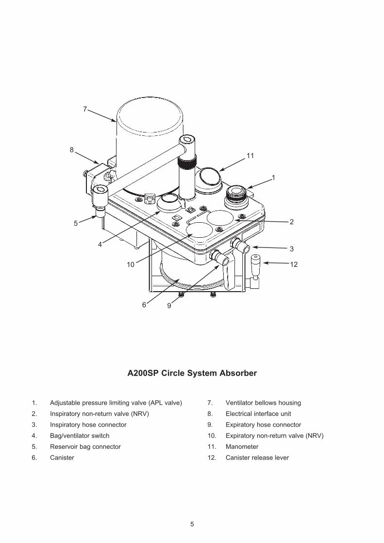
A200SP Circle System Absorber
1. Adjustable pressure limiting valve (APL valve) 7. Ventilator bellows housing
2. Inspiratory non-return valve (NRV) 8. Electrical interface unit
3. Inspiratory hose connector 9. Expiratory hose connector
4. Bag/ventilator switch 10. Expiratory non-return valve (NRV)
5. Reservoir bag connector 11. Manometer
6. Canister 12. Canister release lever
4
10
7
2
3
12
5
1
6 9
811
6
3. DESCRIPTION
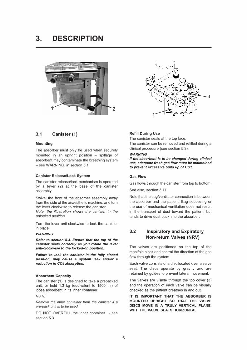
3.1 Canister (1)
Mounting
The absorber must only be used when securely
mounted in an upright position – spillage of
absorbent may contaminate the breathing system
– see WARNING, in section 5.1.
Canister Release/Lock System
The canister release/lock mechanism is operated
by a lever (2) at the base of the canister
assembly.
Swivel the front of the absorber assembly away
from the side of the anaesthetic machine, and turn
the lever clockwise to release the canister.
Note: the illustration shows the canister in theunlocked position.
Turn the lever anti-clockwise to lock the canister
in place
WARNINGRefer to section 5.3. Ensure that the top of thecanister seals correctly as you rotate the leveranti-clockwise to the locked-on position.
Failure to lock the canister in the fully closedposition, may cause a system leak and/or areduction in CO2 absorption.
Absorbent Capacity
The canister (1) is designed to take a prepacked
unit, or hold 1.3 kg (equivalent to 1500 ml) of
loose absorbent in its inner container.
NOTE
Remove the inner container from the canister if apre-pack unit is to be used.
DO NOT OVERFILL the inner container - see
section 5.3.
Refill During Use
The canister seals at the top face.
The canister can be removed and refilled during a
clinical procedure (see section 5.3).
WARNINGIf the absorbent is to be changed during clinicaluse, adequate fresh gas flow must be maintainedto prevent excessive build up of CO2.
Gas Flow
Gas flows through the canister from top to bottom.
See also, section 3.11.
Note that the bag/ventilator connection is between
the absorber and the patient. Bag squeezing or
the use of mechanical ventilation does not result
in the transport of dust toward the patient, but
tends to drive dust back into the absorber.
3.2 Inspiratory and Expiratory
Non-return Valves (NRV)
The valves are positioned on the top of the
manifold block and control the direction of the gas
flow through the system.
Each valve consists of a disc located over a valve
seat. The discs operate by gravity and are
retained by guides to prevent lateral movement.
The valves are visible through the top cover (3)
and the operation of each valve can be visually
checked as the patient breathes in and out.
IT IS IMPORTANT THAT THE ABSORBER IS
MOUNTED UPRIGHT SO THAT THE VALVE
DISCS MOVE IN A TRULY VERTICAL PLANE,
WITH THE VALVE SEATS HORIZONTAL.
3
121
7
DESCRIPTION
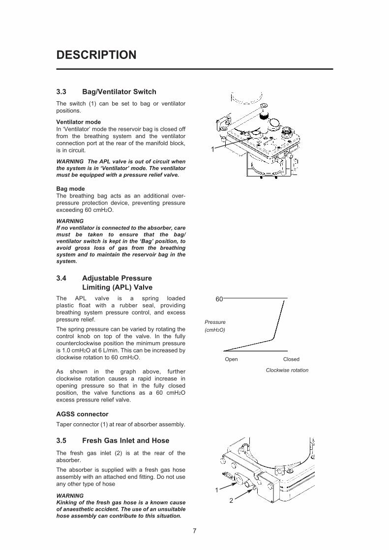
3.3 Bag/Ventilator Switch
The switch (1) can be set to bag or ventilator
positions.
Ventilator mode
In ‘Ventilator’ mode the reservoir bag is closed off
from the breathing system and the ventilator
connection port at the rear of the manifold block,
is in circuit.
WARNING The APL valve is out of circuit whenthe system is in ‘Ventilator’ mode. The ventilatormust be equipped with a pressure relief valve.
Bag mode
The breathing bag acts as an additional over-
pressure protection device, preventing pressure
exceeding 60 cmH2O.
WARNINGIf no ventilator is connected to the absorber, caremust be taken to ensure that the bag/ventilator switch is kept in the ‘Bag’ position, toavoid gross loss of gas from the breathingsystem and to maintain the reservoir bag in thesystem.
3.4 Adjustable Pressure
Limiting (APL) Valve
The APL valve is a spring loaded
plastic float with a rubber seal, providing
breathing system pressure control, and excess
pressure relief.
The spring pressure can be varied by rotating the
control knob on top of the valve. In the fully
counterclockwise position the minimum pressure
is 1.0 cmH2O at 6 L/min. This can be increased by
clockwise rotation to 60 cmH2O.
As shown in the graph above, further
clockwise rotation causes a rapid increase in
opening pressure so that in the fully closed
position, the valve functions as a 60 cmH2O
excess pressure relief valve.
AGSS connector
Taper connector (1) at rear of absorber assembly.
3.5 Fresh Gas Inlet and Hose
The fresh gas inlet (2) is at the rear of the
absorber.
The absorber is supplied with a fresh gas hose
assembly with an attached end fitting. Do not use
any other type of hose
WARNINGKinking of the fresh gas hose is a known causeof anaesthetic accident. The use of an unsuitablehose assembly can contribute to this situation.
60
Pressure(cmH2O)
Open Closed
Clockwise rotation
2
1
1
8
DESCRIPTION
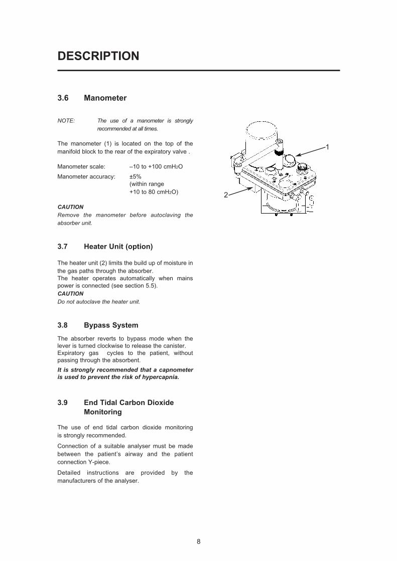
3.6 Manometer
NOTE: The use of a manometer is stronglyrecommended at all times.
The manometer (1) is located on the top of the
manifold block to the rear of the expiratory valve .
Manometer scale: –10 to +100 cmH2O
Manometer accuracy: ±5%
(within range
+10 to 80 cmH2O)
CAUTIONRemove the manometer before autoclaving theabsorber unit.
3.7 Heater Unit (option)
The heater unit (2) limits the build up of moisture in
the gas paths through the absorber.
The heater operates automatically when mains
power is connected (see section 5.5).
CAUTIONDo not autoclave the heater unit.
3.8 Bypass System
The absorber reverts to bypass mode when the
lever is turned clockwise to release the canister.
Expiratory gas cycles to the patient, without
passing through the absorbent.
It is strongly recommended that a capnometeris used to prevent the risk of hypercapnia.
3.9 End Tidal Carbon Dioxide
Monitoring
The use of end tidal carbon dioxide monitoring
is strongly recommended.
Connection of a suitable analyser must be made
between the patient’s airway and the patient
connection Y-piece.
Detailed instructions are provided by the
manufacturers of the analyser.
1
2

3.10 Interface to AV-S Ventilator
The absorber is designed to interface with the AV-S
Ventilator and the ventilator bellows unit (1) is built into
the absorber.
The interface cable links the connector (2) on the
ventilator control panel to the multifunction connector (3)
on the interface unit at the rear of the absorber.
a) The A200SP is fitted with fitted with a sensor that
detects the position of the absorber bag/vent
control switch (4).
A mechanical link actuates the sensor and the
signal cabling is routed internally to connector (3)
b) Operation of the Bag/Vent control will trigger
automatic Mode switching on the AV-S ventilator,
as follows:
i) Ventilator in Volume or Pressure mode
Switching the absorber Bag/Vent control
from Vent to Bag
- the ventilator will change from Volume
Mode, or Pressure Mode, into
Spontaneous Mode.
ii) Ventilator in Spontaneous Mode
Switching the absorber Bag/Vent control
from Bag to Vent
Note that the mode switching operation isdependant on the original selection processused to reach Spontaneous Mode:
A) If the ventilator was previously in
Volume, or Pressure, or Special Mode,
and Spontaneous Mode was automatically
selected by the operation of the bag/vent
control (from Vent to Bag, as described
above):
- the ventilator will now revert to that
previous mode.
B) If the ventilator was in Standby Mode,
and Spontaneous Mode was selected on-
screen:
- the ventilator will revert to Volume Mode.
NOTEa) operation of the absorber Bag/Vent control willhave no effect on the ventilator unless the aboveconditions are met.
b) This function can be enabled/disabled throughthe on-screen Service sub-menu (see appendix, inthe ventilator user manual).
4
1
3
2
DESCRIPTION
9
10
DESCRIPTION
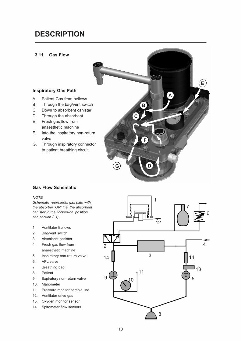
Inspiratory Gas Path
A. Patient Gas from bellows
B. Through the bag/vent switch
C. Down to absorbent canister
D. Through the absorbent
E. Fresh gas flow from
anaesthetic machine
F. Into the inspiratory non-return
valve
G. Through inspiratory connector
to patient breathing circuit
G D
F
C
B
A
E
3.11 Gas Flow
Gas Flow Schematic
NOTESchematic represents gas path withthe absorber ‘ON’ (i.e. the absorbentcanister in the ‘locked-on’ position,see section 3.1).
1. Ventilator Bellows
2. Bag/vent switch
3. Absorbent canister
4. Fresh gas flow from
anaesthetic machine
5. Inspiratory non-return valve
6. APL valve
7. Breathing bag
8. Patient
9. Expiratory non-return valve
10. Manometer
11. Pressure monitor sample line
12. Ventilator drive gas
13. Oxygen monitor sensor
14. Spirometer flow sensors
1
7
6
2
12
13
1414
11
10
3
5
4
8
9
11
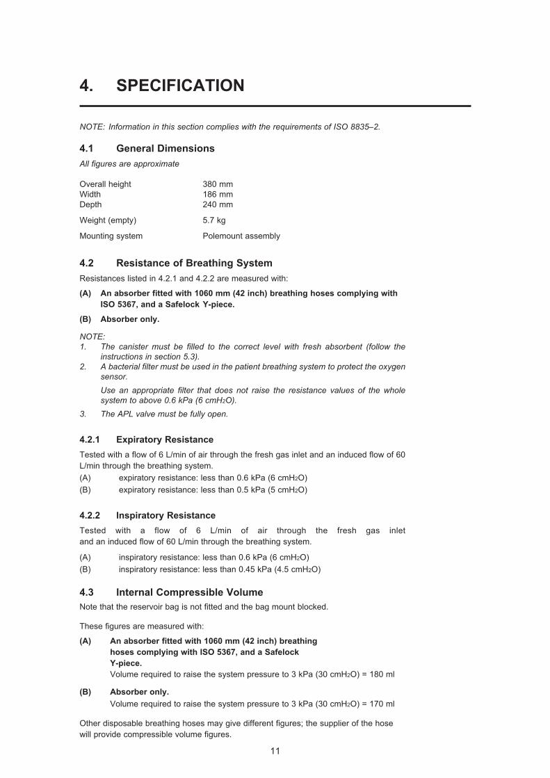
4. SPECIFICATION
NOTE: Information in this section complies with the requirements of ISO 8835–2.
4.1 General Dimensions
All figures are approximate
Overall height 380 mm
Width 186 mm
Depth 240 mm
Weight (empty) 5.7 kg
Mounting system Polemount assembly
4.2 Resistance of Breathing System
Resistances listed in 4.2.1 and 4.2.2 are measured with:
(A) An absorber fitted with 1060 mm (42 inch) breathing hoses complying with
ISO 5367, and a Safelock Y-piece.
(B) Absorber only.
NOTE: 1. The canister must be filled to the correct level with fresh absorbent (follow the
instructions in section 5.3).2. A bacterial filter must be used in the patient breathing system to protect the oxygen
sensor.Use an appropriate filter that does not raise the resistance values of the wholesystem to above 0.6 kPa (6 cmH2O).
3. The APL valve must be fully open.
4.2.1 Expiratory Resistance
Tested with a flow of 6 L/min of air through the fresh gas inlet and an induced flow of 60
L/min through the breathing system.
(A) expiratory resistance: less than 0.6 kPa (6 cmH2O)
(B) expiratory resistance: less than 0.5 kPa (5 cmH2O)
4.2.2 Inspiratory Resistance
Tested with a flow of 6 L/min of air through the fresh gas inlet
and an induced flow of 60 L/min through the breathing system.
(A) inspiratory resistance: less than 0.6 kPa (6 cmH2O)
(B) inspiratory resistance: less than 0.45 kPa (4.5 cmH2O)
4.3 Internal Compressible Volume
Note that the reservoir bag is not fitted and the bag mount blocked.
These figures are measured with:
(A) An absorber fitted with 1060 mm (42 inch) breathing
hoses complying with ISO 5367, and a Safelock
Y-piece.
Volume required to raise the system pressure to 3 kPa (30 cmH2O) = 180 ml
(B) Absorber only.
Volume required to raise the system pressure to 3 kPa (30 cmH2O) = 170 ml
Other disposable breathing hoses may give different figures; the supplier of the hose
will provide compressible volume figures.
12
SPECIFICATION
4.4 System Leakage Rate
The patient connection port is sealed and the APL valve fully closed.
These figures are measured with:
(A) An absorber fitted with 1060 mm (42 inch) breathing
hoses complying with ISO 5367, and a Safelock Y-piece.
Absorber ‘ON’ , canister in locked-on position.
Leakage rate: less than 50 ml/min at 3 kPa (30 cmH2O)
(B) Absorber only.
Absorber ‘OFF’, canister detached.
Leakage rate: less than 50 ml/min at 3 kPa (30 cmH2O)
4.5 Canister Capacity and Resistance
4.5.1 Canister Capacity
When filled to the correct level (see section 5.3), the canister inner container holds
1.3 kg (2.87 lb) of absorbent (1500 ml).
Recommended absorbent:Soda lime, with a colour indicator, 4-8 mesh.Use bulk packed (loose) or pre-packs.
Note
i) The absorber canister is not electrically conductive.
ii) Cleaning and sterilisation details are given in section 8.
4.5.2 Canister Resistance
The resistance of a freshly filled canister is less than 0.2 kPa (2 cmH2O) at 60 L/min.
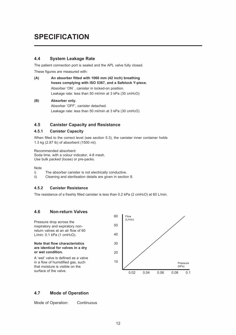
4.6 Non-return Valves
Pressure drop across the
inspiratory and expiratory non-
return valves at an air flow of 60
L/min: 0.1 kPa (1 cmH2O).
Note that flow characteristics
are identical for valves in a dry
or wet condition.
A ‘wet’ valve is defined as a valve
in a flow of humidified gas, such
that moisture is visible on the
surface of the valve.
4.7 Mode of Operation
Mode of Operation: Continuous
60
50
40
30
20
10
0.02 0.04 0.06 0.08 0.1
Pressure(kPa)
Flow(L/min)
13
SPECIFICATION
4.8 Heater (option)
Voltage 110 - 240 VAC
Current 1.5 - 0.7 A
Frequency 50/60 Hz
Fuse T2 AH 250 V
Electro-magnetic compatibility:
The A200SP meets the requirements of EN60601-1-2
(Electromagnetic compatibility - requirements and tests).
4.9 Device Classification and Labelling
Type B Applied Part
Degree of protection against electric shock
This symbol denotes: Type B equipment:
Class 1 Classification
Type of protection against electric shock
Class 1
IPX0 Ingress protection
Classification according to the degree of protection against ingress of water
IPX0 (not protected)
Labelling
This symbol denotes: Refer to the User Manual
4.10 Environmental
Operating:
Temperature 15 to 30oC (59 to 86oF)
Humidity 10 - 95% RH (relative humidity), non-condensing
Altitude Up to 2775 m (9000 feet)
Air Pressure 70 - 110 kPa
MRI compatibility The A200SP absorber is not suitable for use in an MRI
environment
Electro-magnetic compatibility:
The A200SP meets the requirements of EN60601-1-2
(Electromagnetic compatibility - requirements and tests).
Storage and Transport:
Temperature -5 to 40oC (23 to 104oF).
Humidity 10 - 95% RH (relative humidity), non-condensing
Air Pressure 11.5 - 110 kPa
Disposal at end of useful life - risk assessment
There are no risks associated with disposal of this product.
Follow your hospital, local, state and federal regulations.
14
5. INSTALLATION AND OPERATION
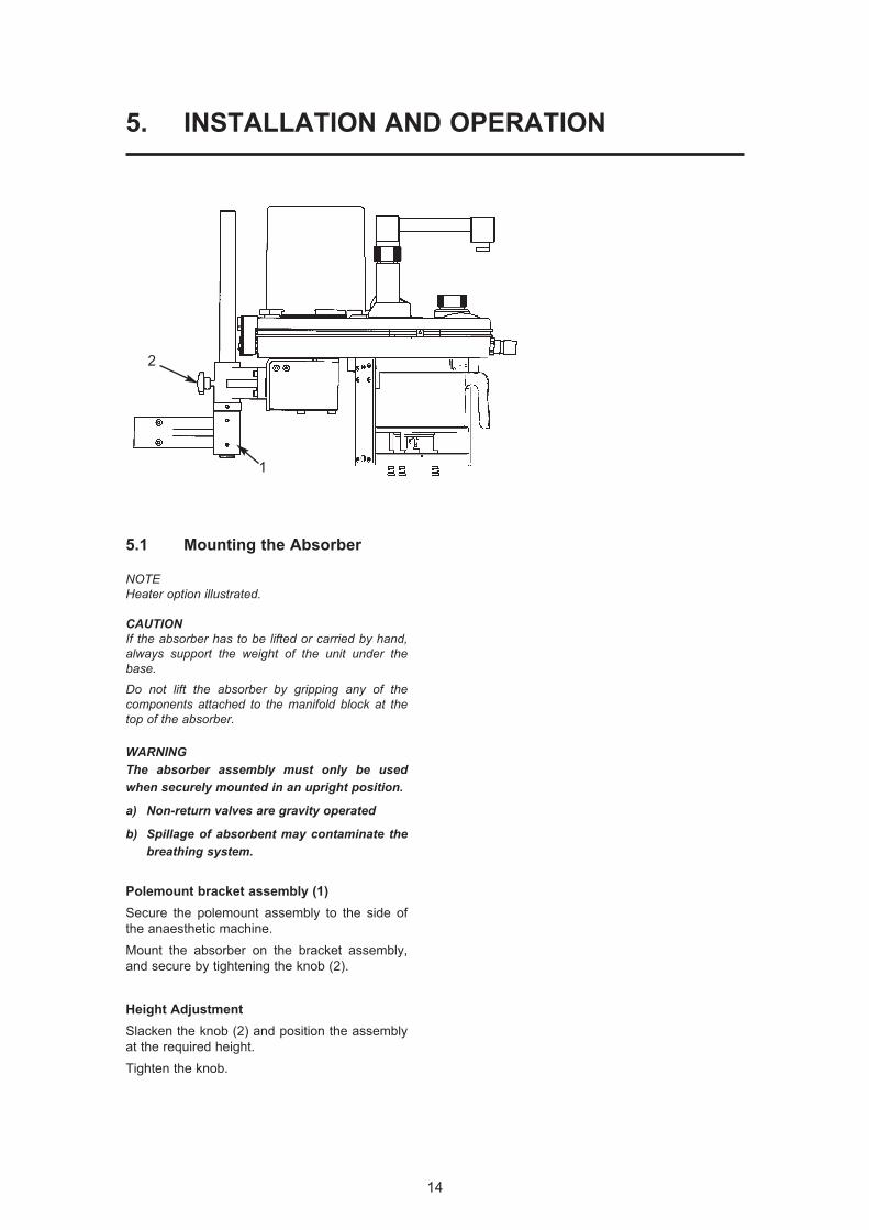
5.1 Mounting the Absorber
NOTEHeater option illustrated.
CAUTIONIf the absorber has to be lifted or carried by hand,always support the weight of the unit under thebase.
Do not lift the absorber by gripping any of the components attached to the manifold block at thetop of the absorber.
WARNINGThe absorber assembly must only be usedwhen securely mounted in an upright position.
a) Non-return valves are gravity operated
b) Spillage of absorbent may contaminate thebreathing system.
Polemount bracket assembly (1)
Secure the polemount assembly to the side of
the anaesthetic machine.
Mount the absorber on the bracket assembly,
and secure by tightening the knob (2).
Height Adjustment
Slacken the knob (2) and position the assembly
at the required height.
Tighten the knob.
1
2

15
INSTALLATION AND OPERATION
Note
1. AV-S has spirometry and oxygen monitor.
2. Interface cabling is shown for Prima SP2
On/Off switch and A200SP Bag/Vent
switch.
5.2 System Connection
Hoses and Cables Schematic:
AV-S and A200SP Absorber
1
23
6
78
12
131614
26
1715
12
19
18
2024
2523
28
27
29
26
21
22
9
1011
4
5
Notea) AV-S has spirometry and oxygen monitor.b) Interface cabling is shown for Prima SP2 On/Off switch and
A200SP Bag/Vent switch.
1. Bellows
2. Ventilator Control Unit
3. Outlets to Anaesthetic Gas Scavenging System (AGSS)
4. Bacterial Filter
5. Absorber valve block
6. Heat and moisture exchanger
7. Patient
8. CGO on anaesthetic machine (Fresh Gas Supply)
9. Auxiliary Outlet on anaesthetic machine (Drive Gas Supply)
10. Flow sensor - expiratory
11. Flow sensor - inspiratory
12 Connectors - sensor - pressure monitor
13. Expiratory Valve - Absorber
14. Inspiratory Valve - Absorber
15. Inlet - from Ventilator Bellows
16. Connector - Reservoir Bag
17. Inlet - Absorber - Fresh Gas Supply
18. Drive Gas Inlet - Ventilator
19. Drive gas Outlet - ventilator control unit to bellows
20. Outlet - Exhaust Valve
21. Inlet - Bellows Drive Gas
22. Outlet - to breathing system
23. Input socket - Oxygen monitor sensor
24. Input socket - Prima SP2 interface
(SP on/off switch)
25. Input socket:
(i) A200SP Absorber Bag/Vent control position
(ii) Spirometer sensor signal
26. Interface connections on Prima SP2 and A200SP
27. APL Valve
28 Outlet from APL Valve to AGSS
29 Oxygen sensor
16
INSTALLATION AND OPERATION
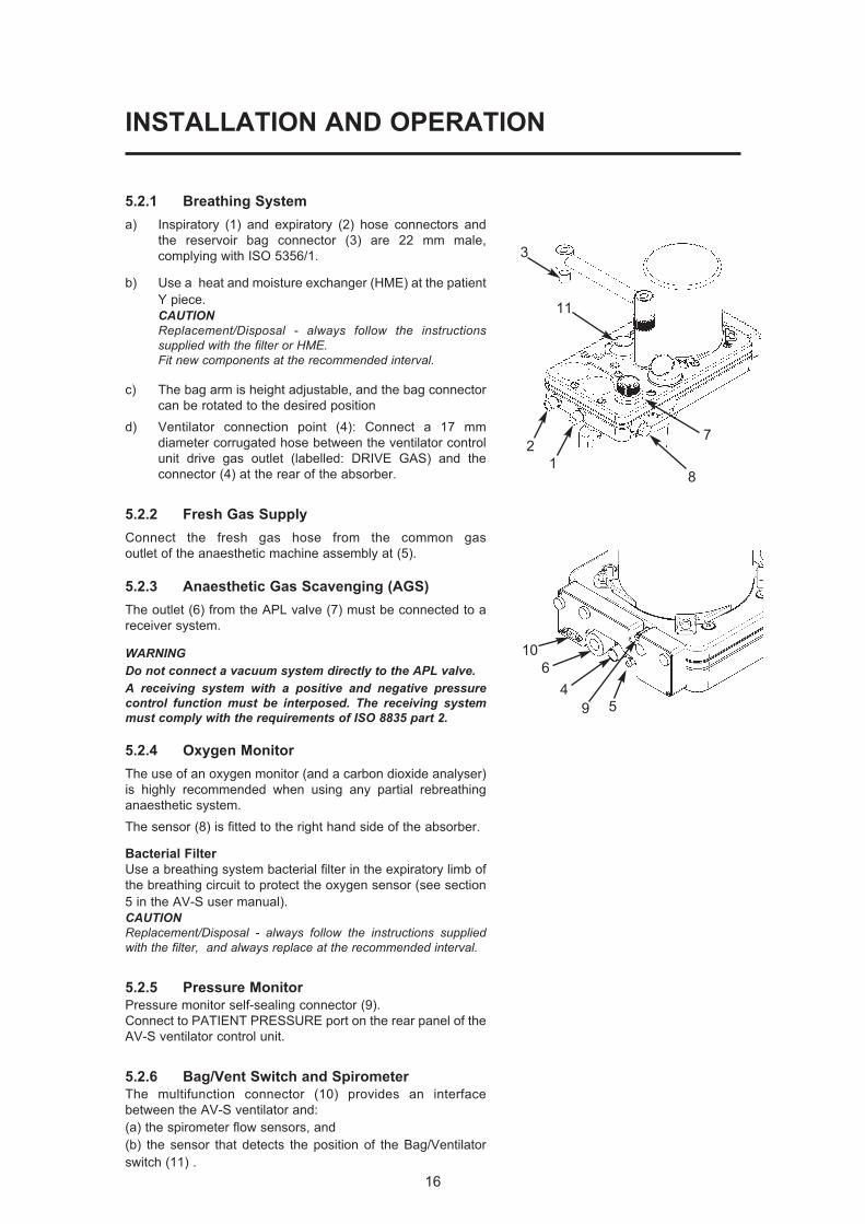
5.2.1 Breathing System
a) Inspiratory (1) and expiratory (2) hose connectors and
the reservoir bag connector (3) are 22 mm male,
complying with ISO 5356/1.
b) Use a heat and moisture exchanger (HME) at the patient
Y piece.
CAUTIONReplacement/Disposal - always follow the instructionssupplied with the filter or HME.Fit new components at the recommended interval.
c) The bag arm is height adjustable, and the bag connector
can be rotated to the desired position
d) Ventilator connection point (4): Connect a 17 mm
diameter corrugated hose between the ventilator control
unit drive gas outlet (labelled: DRIVE GAS) and the
connector (4) at the rear of the absorber.
5.2.2 Fresh Gas Supply
Connect the fresh gas hose from the common gas
outlet of the anaesthetic machine assembly at (5).
5.2.3 Anaesthetic Gas Scavenging (AGS)
The outlet (6) from the APL valve (7) must be connected to a
receiver system.
WARNINGDo not connect a vacuum system directly to the APL valve. A receiving system with a positive and negative pressurecontrol function must be interposed. The receiving systemmust comply with the requirements of ISO 8835 part 2.
5.2.4 Oxygen Monitor
The use of an oxygen monitor (and a carbon dioxide analyser)
is highly recommended when using any partial rebreathing
anaesthetic system.
The sensor (8) is fitted to the right hand side of the absorber.
Bacterial Filter
Use a breathing system bacterial filter in the expiratory limb of
the breathing circuit to protect the oxygen sensor (see section
5 in the AV-S user manual).
CAUTIONReplacement/Disposal - always follow the instructions suppliedwith the filter, and always replace at the recommended interval.
5.2.5 Pressure Monitor
Pressure monitor self-sealing connector (9).
Connect to PATIENT PRESSURE port on the rear panel of the
AV-S ventilator control unit.
5.2.6 Bag/Vent Switch and Spirometer
The multifunction connector (10) provides an interface
between the AV-S ventilator and:
(a) the spirometer flow sensors, and
(b) the sensor that detects the position of the Bag/Ventilator
switch (11) .
1
2
3
459
6
10
11
8
7
INSTALLATION AND OPERATION
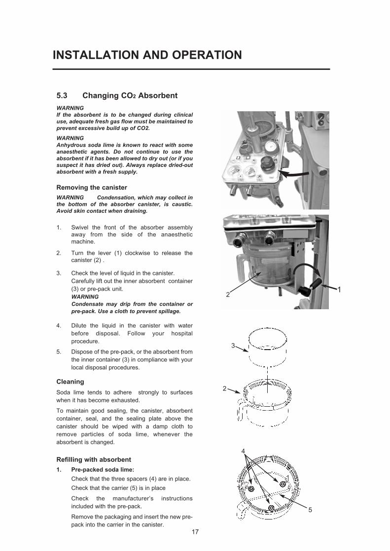
5.3 Changing CO2 Absorbent
WARNINGIf the absorbent is to be changed during clinicaluse, adequate fresh gas flow must be maintained toprevent excessive build up of CO2.
WARNINGAnhydrous soda lime is known to react with someanaesthetic agents. Do not continue to use theabsorbent if it has been allowed to dry out (or if yoususpect it has dried out). Always replace dried-outabsorbent with a fresh supply.
Removing the canister
WARNING Condensation, which may collect inthe bottom of the absorber canister, is caustic.Avoid skin contact when draining.
1. Swivel the front of the absorber assembly
away from the side of the anaesthetic
machine.
2. Turn the lever (1) clockwise to release the
canister (2) .
3. Check the level of liquid in the canister.
Carefully lift out the inner absorbent container
(3) or pre-pack unit.
WARNINGCondensate may drip from the container orpre-pack. Use a cloth to prevent spillage.
4. Dilute the liquid in the canister with water
before disposal. Follow your hospital
procedure.
5. Dispose of the pre-pack, or the absorbent from
the inner container (3) in compliance with your
local disposal procedures.
Cleaning
Soda lime tends to adhere strongly to surfaces
when it has become exhausted.
To maintain good sealing, the canister, absorbent
container, seal, and the sealing plate above the
canister should be wiped with a damp cloth to
remove particles of soda lime, whenever the
absorbent is changed.
Refilling with absorbent
1. Pre-packed soda lime:
Check that the three spacers (4) are in place.
Check that the carrier (5) is in place
Check the manufacturer’s instructions
included with the pre-pack.
Remove the packaging and insert the new pre-
pack into the carrier in the canister.
17
4
5
21
2
3

18
INSTALLATION AND OPERATION
2. Bulk packed (loose) soda lime:
WARNINGUnderfilling can lead to inefficient CO2absorbtion. Overfilling may result in poor sealing of thecanister, due to caking of granules and abrasionof the canister seal.
Check that the container (3) is clean and dry and
empty of dust or soda lime granules.
Place the container on a horizontal surface and
fill it with soda lime up to a level 25 mm (1 inch)
below the top.
Do not fill above this level.
Check that the three spacers (4) are fitted, and
place the container in the canister.
Refitting the canister
1. Fit the canister (2) and check that it is located
centrally within the base plate (6).
Turn the lever (1) anti-clockwise to lock the
canister in place.
The top of the canister must engage correctly
into the seal (7) as you rotate the lever anti-
clockwise to the locked-on position.
WARNINGFailure to lock the canister in the fully closedposition, may cause a system leak and/or areduction in CO2 absorption.
2. Leak test the absorber – see section 6.2.
5.4 Manometer
The manometer (1) is located on the top of the
manifold block, to the rear of the inspiratory valve.
If the manometer has been removed and refitted,
function test the absorber, checking for leaks at the
manometer, before clinical use.
CAUTION Remove the manometer before autoclavingthe absorber unit.
5.5 Heater (option)
Connect the cable (mains electrical supply) to the
socket (1) on the back of the heater unit (2).
Secure the cable with the safety clip (3).
The heater operates automatically, and the warning
lamp (4) is illuminated, when mains power is
connected.
The heater has a thermostatic control system.
CAUTIONDo not immerse or autoclave the heater assembly.Remove the unit before the absorber assembly is cleanedand sterilised (see section 8.4).
43
25 mm
1
1
2
43
2
6
7
1
19
6. PRE-USE CHECKS
6.1 Pre-use Checklist
1. Check the absorbent, replace if necessary.
Before refitting the canister, check that the
sealing surfaces are clean and dust free.
Ensure that the canister is fully rotated and
seals securely when refitted (see 5.3).
2. Check that the fresh gas hose is connected
to the anaesthetic machine.
Note that the anaesthetic machine must be
leak tested before the absorber pre-use
checks are made.
3. Leak test the absorber – see section 6.2
4. Carry out a function check and
pressure relief test on the APL valve –
see section 6.3.
5. Check the inspiratory and expiratory non-
return valves for correct operation – see
section 6.4.
6. Check the Bag/Ventilator switch for correct
operation – see section 6.5.
7. Heater (if fitted) - connect to mains supply
(see 5.5) and check operation.
8. Carry out a leak test with the canister
removed - see 6.6
9. Repeat the absorber leak test – see section
6.2.
20
PRE-USE CHECKS
The procedures detailed in sections 6.2 to
6.6 must be carried out in the order listed.
The absorber must be attached to an
anaesthetic machine, which must be leak tested
before the checks are carried out.
Check that the manometer is zeroed before use.
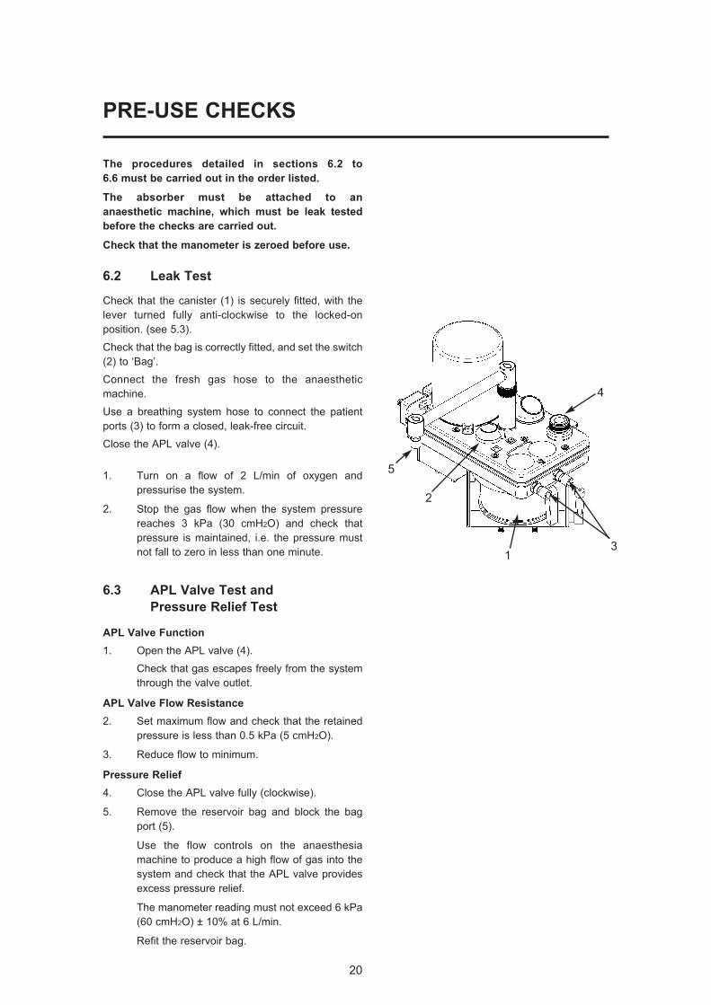
6.2 Leak Test
Check that the canister (1) is securely fitted, with the
lever turned fully anti-clockwise to the locked-on
position. (see 5.3).
Check that the bag is correctly fitted, and set the switch
(2) to ‘Bag’.
Connect the fresh gas hose to the anaesthetic
machine.
Use a breathing system hose to connect the patient
ports (3) to form a closed, leak-free circuit.
Close the APL valve (4).
1. Turn on a flow of 2 L/min of oxygen and
pressurise the system.
2. Stop the gas flow when the system pressure
reaches 3 kPa (30 cmH2O) and check that
pressure is maintained, i.e. the pressure must
not fall to zero in less than one minute.
6.3 APL Valve Test and
Pressure Relief Test
APL Valve Function
1. Open the APL valve (4).
Check that gas escapes freely from the system
through the valve outlet.
APL Valve Flow Resistance
2. Set maximum flow and check that the retained
pressure is less than 0.5 kPa (5 cmH2O).
3. Reduce flow to minimum.
Pressure Relief
4. Close the APL valve fully (clockwise).
5. Remove the reservoir bag and block the bag
port (5).
Use the flow controls on the anaesthesia
machine to produce a high flow of gas into the
system and check that the APL valve provides
excess pressure relief.
The manometer reading must not exceed 6 kPa
(60 cmH2O) ± 10% at 6 L/min.
Refit the reservoir bag.
3
5
2
1
4
21
PRE-USE CHECKS
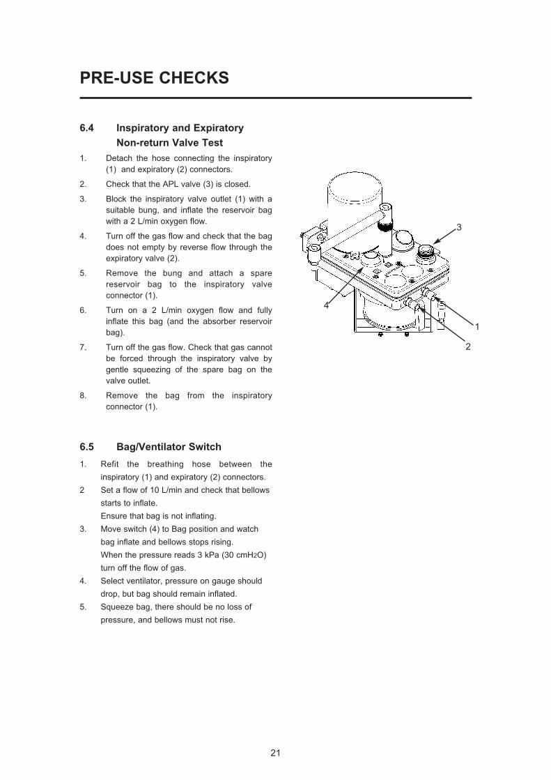
6.4 Inspiratory and Expiratory
Non-return Valve Test
1. Detach the hose connecting the inspiratory
(1) and expiratory (2) connectors.
2. Check that the APL valve (3) is closed.
3. Block the inspiratory valve outlet (1) with a
suitable bung, and inflate the reservoir bag
with a 2 L/min oxygen flow.
4. Turn off the gas flow and check that the bag
does not empty by reverse flow through the
expiratory valve (2).
5. Remove the bung and attach a spare
reservoir bag to the inspiratory valve
connector (1).
6. Turn on a 2 L/min oxygen flow and fully
inflate this bag (and the absorber reservoir
bag).
7. Turn off the gas flow. Check that gas cannot
be forced through the inspiratory valve by
gentle squeezing of the spare bag on the
valve outlet.
8. Remove the bag from the inspiratory
connector (1).
6.5 Bag/Ventilator Switch
1. Refit the breathing hose between the
inspiratory (1) and expiratory (2) connectors.
2 Set a flow of 10 L/min and check that bellows
starts to inflate.
Ensure that bag is not inflating.
3. Move switch (4) to Bag position and watch
bag inflate and bellows stops rising.
When the pressure reads 3 kPa (30 cmH2O)
turn off the flow of gas.
4. Select ventilator, pressure on gauge should
drop, but bag should remain inflated.
5. Squeeze bag, there should be no loss of
pressure, and bellows must not rise.
2
4
3
1

22
PRE-USE CHECKS
6.6 Leak Test - Absorber Canister
Detached
1. Turn the lever (1) clockwise to release the
canister (2) .
2. Set the switch (3) to Bag position and close
APL valve (4).
3. Pressurise the system to 3 kPa (30 cmH2O)
and turn off the gas flow.
4. Check that pressure does not fall to zero
within one minute.
5. Refit absorbent canister.
Turn the lever (1) anti-clockwise to lock the
canister in place.
Ensure that the top of the canister
engages correctly into the seal (5) as
you rotate the lever anti-clockwise to the
locked-on position.
WARNINGFailure to lock the canister in the fullyclosed position, may cause a system leakand/or a reduction in CO2 absorption.
6. A pressure loss will occur as valves operate
during refitment.
Repressurise the system to 3 kPa (30
cmH2O) and turn off gas flow.
7. Check that pressure does not fall to zero
within one minute, then open APL valve to
release pressure.
3
2
4
1
5
1
7. MAINTENANCE
Maintenance
WARNING1. User maintenance is restricted to cleaning
the outside surfaces of the device, asdetailed in this section.
2. Other procedures detailed in this sectionmust be carried out by trained techniciansonly.
3. Service and repair operations must onlybe carried out by an engineer trained bythe manufacturer. The warranty for thisproduct is void if the product is notmaintained in accordance with the serviceschedule detailed below, and theprocedures published in the ServiceManual for this product.
7.1 Service Schedule
Servicing and repairs must only be carried
out by engineers trained by the manufacturer.
(a) Six-monthly inspection and function
testing.
(b) Annual service which includes routine
replacement of seals etc., as preventive
maintenance.
7.2 Canister and Seals
Cleanliness is the essential requirement for all
components in contact with absorbent.
Soda lime tends to adhere strongly to surfaces
when it has become exhausted.
To maintain good sealing, the canister,
absorbent container, seal, and the sealing plate
above the canister should be wiped with a damp
cloth to remove particles of soda lime, whenever
the absorbent is changed.
These components should be scrubbed under
running water when the complete system is
dismantled for sterilisation or disinfection.
See section 8.4.
23
24
MAINTENANCE
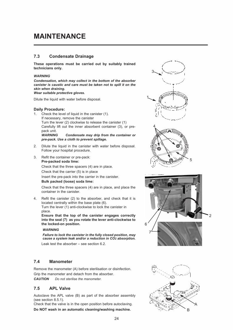
7.3 Condensate Drainage
These operations must be carried out by suitably trained
technicians only.
WARNINGCondensation, which may collect in the bottom of the absorbercanister is caustic and care must be taken not to spill it on theskin when draining. Wear suitable protective gloves.
Dilute the liquid with water before disposal.
Daily Procedure:1. Check the level of liquid in the canister (1).
If necessary, remove the canister
Turn the lever (2) clockwise to release the canister (1)
Carefully lift out the inner absorbent container (3), or pre-
pack unit.
WARNING Condensate may drip from the container orpre-pack. Use a cloth to prevent spillage.
2. Dilute the liquid in the canister with water before disposal.
Follow your hospital procedure.
3. Refit the container or pre-pack:
Pre-packed soda lime:
Check that the three spacers (4) are in place.
Check that the carrier (5) is in place
Insert the pre-pack into the carrier in the canister.
Bulk packed (loose) soda lime:
Check that the three spacers (4) are in place, and place the
container in the canister.
4. Refit the canister (2) to the absorber, and check that it is
located centrally within the base plate (6).
Turn the lever (1) anti-clockwise to lock the canister in
place.
Ensure that the top of the canister engages correctly
into the seal (7) as you rotate the lever anti-clockwise to
the locked-on position.
WARNINGFailure to lock the canister in the fully closed position, maycause a system leak and/or a reduction in CO2 absorption.
Leak test the absorber – see section 6.2.
7.4 Manometer
Remove the manometer (A) before sterilisation or disinfection.
Grip the manometer and detach from the absorber.
CAUTION Do not sterilise the manometer.
7.5 APL Valve
Autoclave the APL valve (B) as part of the absorber assembly
(see section 8.5.1).
Check that the valve is in the open position before autoclaving.
Do NOT wash in an automatic cleaning/washing machine.
1
3
4
5
B
A
7
2
6
25
8. STERILISATION
8.1 Sterilisation Policy
The operations detailed in section 8 must be
carried out by suitably trained technicians only.
Follow your local hospital guidelines.
Autoclavable components are listed in section 8.5.
8.2 Bacterial Filters
The use of respiratory bacterial filters is essential
to protect the oxygen sensor mounted at the side of
the absorber.
Fit a bacterial filter to the expiratory limb of the
breathing circuit.
In addition a heat and moisture exchange (HME) unit
should be fitted at the patient Y-piece.
Refer to the diagram in section 5 – ‘Breathing Circuit
Connections’, and the information on flow resistance in
sections 4.2.1, and 4.2.2.
Filters may be sterilisable or single use. Please read
the labelling supplied by their manufacturer.
CAUTIONReplacement/Disposal - always follow the instructionssupplied with the filter or HME.Always renew components at the recommended interval
NOTE
If a bacterial filter has not been used in the expiratory limbof the breathing circuit, the oxygen sensor may becontaminated and must be replaced.
8.3 Patient Circuit Components
The components should be separated, washed with
warm soap and water solution, rinsed in warm water
and air dried.
For sterilisation, follow the instructions supplied by the
manufacturer.
26
STERILISATION
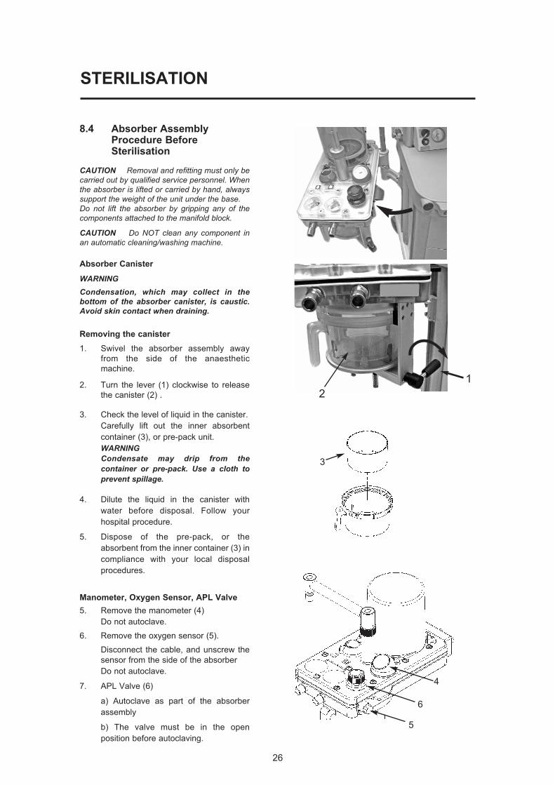
8.4 Absorber AssemblyProcedure BeforeSterilisation
CAUTION Removal and refitting must only becarried out by qualified service personnel. Whenthe absorber is lifted or carried by hand, alwayssupport the weight of the unit under the base.Do not lift the absorber by gripping any of thecomponents attached to the manifold block.
CAUTION Do NOT clean any component inan automatic cleaning/washing machine.
Absorber Canister
WARNING Condensation, which may collect in thebottom of the absorber canister, is caustic.Avoid skin contact when draining.
Removing the canister
1. Swivel the absorber assembly away
from the side of the anaesthetic
machine.
2. Turn the lever (1) clockwise to release
the canister (2) .
3. Check the level of liquid in the canister.
Carefully lift out the inner absorbent
container (3), or pre-pack unit.
WARNINGCondensate may drip from thecontainer or pre-pack. Use a cloth toprevent spillage.
4. Dilute the liquid in the canister with
water before disposal. Follow your
hospital procedure.
5. Dispose of the pre-pack, or the
absorbent from the inner container (3) in
compliance with your local disposal
procedures.
Manometer, Oxygen Sensor, APL Valve
5. Remove the manometer (4)
Do not autoclave.
6. Remove the oxygen sensor (5).
Disconnect the cable, and unscrew the
sensor from the side of the absorber
Do not autoclave.
7. APL Valve (6)
a) Autoclave as part of the absorber
assembly
b) The valve must be in the open
position before autoclaving.
4
5
6
3
2
1
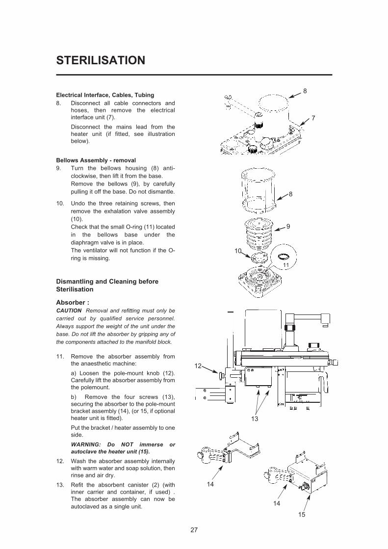
Electrical Interface, Cables, Tubing
8. Disconnect all cable connectors and
hoses, then remove the electrical
interface unit (7).
Disconnect the mains lead from the
heater unit (if fitted, see illustration
below).
Bellows Assembly - removal
9. Turn the bellows housing (8) anti-
clockwise, then lift it from the base.
Remove the bellows (9), by carefully
pulling it off the base. Do not dismantle.
10. Undo the three retaining screws, then
remove the exhalation valve assembly
(10).
Check that the small O-ring (11) located
in the bellows base under the
diaphragm valve is in place.
The ventilator will not function if the O-
ring is missing.
Dismantling and Cleaning before
Sterilisation
Absorber :
CAUTION Removal and refitting must only becarried out by qualified service personnel.Always support the weight of the unit under thebase. Do not lift the absorber by gripping any ofthe components attached to the manifold block.
11. Remove the absorber assembly from
the anaesthetic machine:
a) Loosen the pole-mount knob (12).
Carefully lift the absorber assembly from
the polemount.
b) Remove the four screws (13),
securing the absorber to the pole-mount
bracket assembly (14), (or 15, if optional
heater unit is fitted).
Put the bracket / heater assembly to one
side.
WARNING: Do NOT immerse orautoclave the heater unit (15).
12. Wash the absorber assembly internally
with warm water and soap solution, then
rinse and air dry.
13. Refit the absorbent canister (2) (with
inner carrier and container, if used) .
The absorber assembly can now be
autoclaved as a single unit.
STERILISATION
27
14
14
15
8
9
11
10
12
13
8
7
28
STERILISATION
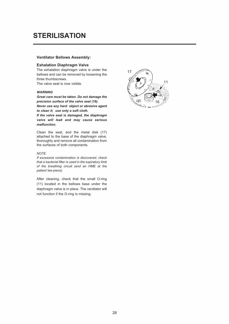
Ventilator Bellows Assembly:
Exhalation Diaphragm Valve
The exhalation diaphragm valve is under the
bellows and can be removed by loosening the
three thumbscrews.
The valve seat is now visible.
WARNINGGreat care must be taken. Do not damage theprecision surface of the valve seat (16). Never use any hard object or abrasive agentto clean it; use only a soft cloth.If the valve seat is damaged, the diaphragmvalve will leak and may cause seriousmalfunction.
Clean the seat, and the metal disk (17)
attached to the base of the diaphragm valve,
thoroughly and remove all contamination from
the surfaces of both components.
NOTE If excessive contamination is discovered, checkthat a bacterial filter is used in the expiratory limbof the breathing circuit (and an HME at thepatient tee-piece).
After cleaning, check that the small O-ring
(11) located in the bellows base under the
diaphragm valve is in place. The ventilator will
not function if the O-ring is missing.
17
16
11
29
STERILISATION
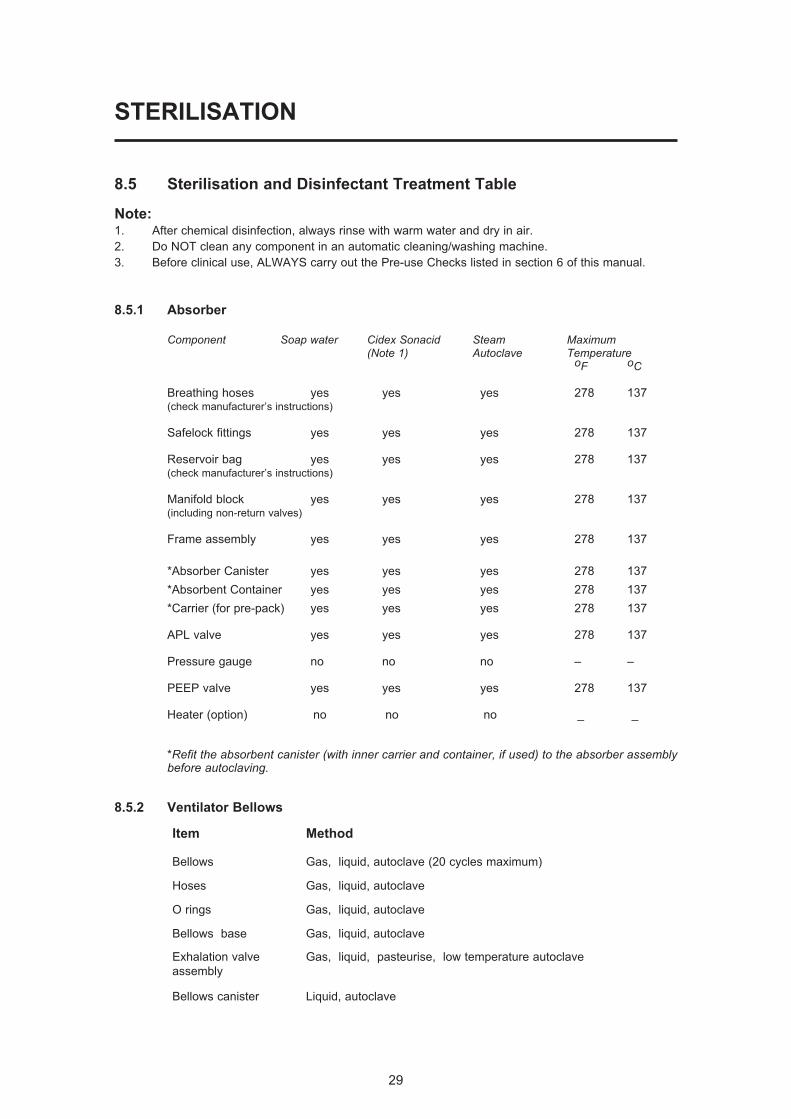
8.5 Sterilisation and Disinfectant Treatment Table
Note:1. After chemical disinfection, always rinse with warm water and dry in air.
2. Do NOT clean any component in an automatic cleaning/washing machine.
3. Before clinical use, ALWAYS carry out the Pre-use Checks listed in section 6 of this manual.
8.5.1 Absorber
Component Soap water Cidex Sonacid Steam Maximum(Note 1) Autoclave Temperature
oF oC
Breathing hoses yes yes yes 278 137(check manufacturer’s instructions)
Safelock fittings yes yes yes 278 137
Reservoir bag yes yes yes 278 137(check manufacturer’s instructions)
Manifold block yes yes yes 278 137(including non-return valves)
Frame assembly yes yes yes 278 137
*Absorber Canister yes yes yes 278 137
*Absorbent Container yes yes yes 278 137
*Carrier (for pre-pack) yes yes yes 278 137
APL valve yes yes yes 278 137
Pressure gauge no no no – –
PEEP valve yes yes yes 278 137
Heater (option) no no no _ _
*Refit the absorbent canister (with inner carrier and container, if used) to the absorber assemblybefore autoclaving.
8.5.2 Ventilator Bellows
Item Method
Bellows Gas, liquid, autoclave (20 cycles maximum)
Hoses Gas, liquid, autoclave
O rings Gas, liquid, autoclave
Bellows base Gas, liquid, autoclave
Exhalation valve Gas, liquid, pasteurise, low temperature autoclave
assembly
Bellows canister Liquid, autoclave
STERILISATION
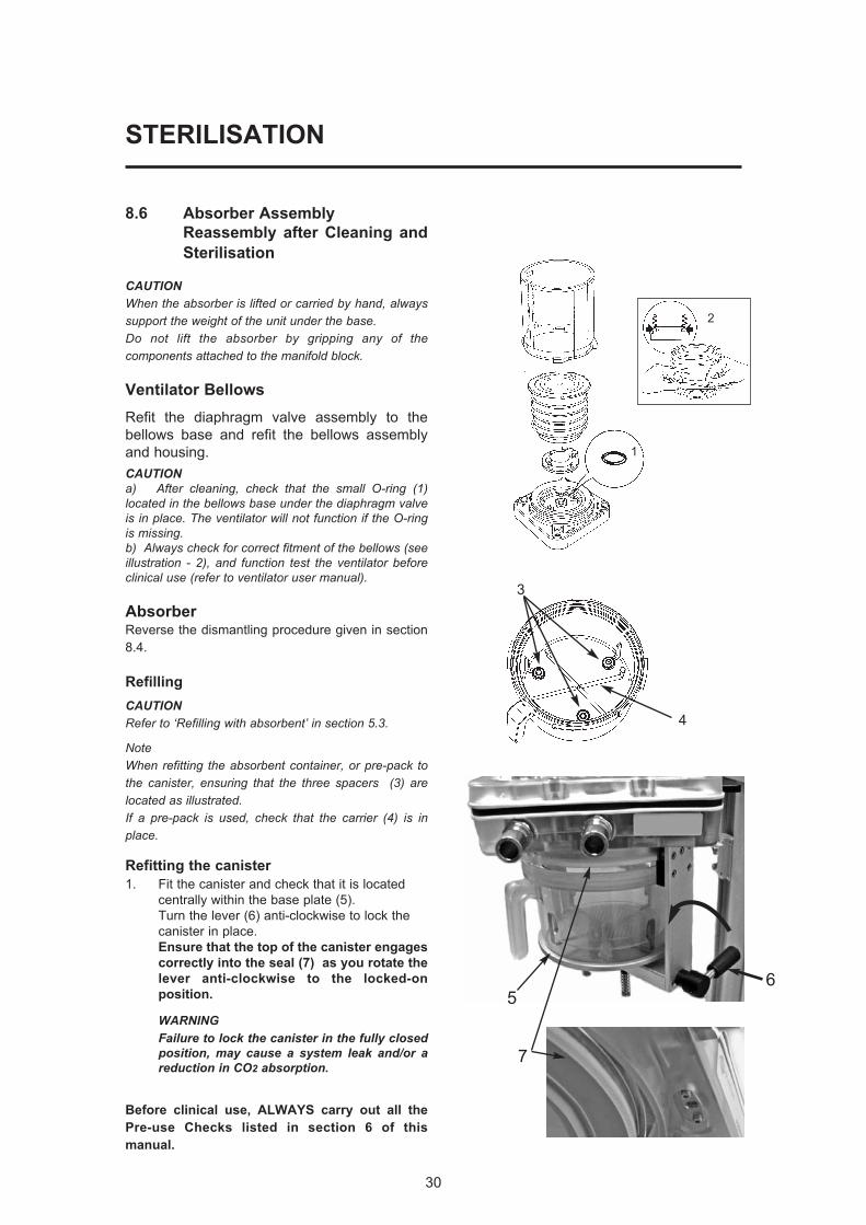
8.6 Absorber Assembly
Reassembly after Cleaning and
Sterilisation
CAUTIONWhen the absorber is lifted or carried by hand, alwayssupport the weight of the unit under the base.Do not lift the absorber by gripping any of thecomponents attached to the manifold block.
Ventilator Bellows
Refit the diaphragm valve assembly to the
bellows base and refit the bellows assembly
and housing.
CAUTIONa) After cleaning, check that the small O-ring (1)located in the bellows base under the diaphragm valveis in place. The ventilator will not function if the O-ringis missing.b) Always check for correct fitment of the bellows (seeillustration - 2), and function test the ventilator beforeclinical use (refer to ventilator user manual).
AbsorberReverse the dismantling procedure given in section
8.4.
Refilling
CAUTIONRefer to ‘Refilling with absorbent’ in section 5.3.
NoteWhen refitting the absorbent container, or pre-pack tothe canister, ensuring that the three spacers (3) arelocated as illustrated.If a pre-pack is used, check that the carrier (4) is inplace.
Refitting the canister
1. Fit the canister and check that it is located
centrally within the base plate (5).
Turn the lever (6) anti-clockwise to lock the
canister in place.
Ensure that the top of the canister engages
correctly into the seal (7) as you rotate the
lever anti-clockwise to the locked-on
position.
WARNINGFailure to lock the canister in the fully closedposition, may cause a system leak and/or areduction in CO2 absorption.
Before clinical use, ALWAYS carry out all the
Pre-use Checks listed in section 6 of this
manual.
30
3
4
1
2
5
7
6
9. APPENDIX
APPENDIX 1
Disposal at end of useful life - risk assessment
There are no risks associated with disposal of this product.
Do not dispose of in landfill, refer to an approved recycling facility.
Follow your hospital, local, state and federal regulations.
31
APPENDIX
APPENDIX 2
Approved Accessories
A200SP Absorber
52582 Absorber detachables - breathing circuit and 3 L bag
51250 Silicon Absorber detachables
51251 Paediatric Silicon Absorber detachables
51041 Breathing Hose
52012 Female Hose Connector
UK Sales
Tel: 01235 547036
Fax: 01235 547023
E-mail: [email protected]
International Sales
Tel: +44 1235 547001
Fax: +44 1235 547021
E-mail: [email protected]
32

Cat. No. 53005
Doc. No. A2 0109UI
February 2009
© Penlon Ltd 2009 All rights reserved.
Penlon Limited
Abingdon Science Park
Barton Lane
Abingdon
OX14 3PH
UK
Technical Support
Tel: 44 (0) 1235 547076
Fax: 44 (0) 1235 547062
E-mail: [email protected]
UK Sales
Tel: 01235 547036
Fax: 01235 547023
E-mail: [email protected]
International Sales
Tel: 44 (0) 1235 547001
Fax: 44 (0) 1235 547021
E-mail: [email protected] Penlon is a member of the InterMed Group