Embed Size (px)
Citation preview

Study on Modular Design of Complex Products Based on the Triple Fusion of Function/Feature/Knowledge1
Li Baotong, Hong Jun
State Key Laboratory for Manufacturing Systems Engineering,
Xi’an Jiaotong University, Xi’an, (710049)
Abstract A modular design methodology based on functional feature analysis is proposed to remedy the existing deficiency in modeling of the design process for complex structural components. In this approach, a partitioning is firstly performed for the complex structural components by mapping the functions to structures layer by layer. Based on this partition, a comprehensive design matrix is then developed to identify the key design mode which is driven by the special function. The design process is also programmed by analyzing the coupled information on both the functional and structural hierarchies. Then, the integrated knowledge model based on object-oriented method and hybrid inference method is constructed, in this model, knowledge can be organized at hierarchical classification and expressed with different forms. Finally, this method has been verified through a case study on an automobile cylinder block. The results indicate that this method is effective in the reduction of design process complexity in product development. In addition, it also supports variable parameters, which is a favorable feature for potential changes of products. Keywords: Functional Feature Partition, Knowledge Unit, Comprehensive Design
Matrix, Knowledge Model
1 Introduction
There are a large number of complex structural components existing in today’s industrial products,
such as large pump, marine crank and automobile engine. Because the design of this kind of
components often requires multi-disciplinary knowledge, it is very difficult to achieve significant
innovation within a short period of time. According to the statistics in industries, only about 20% of
OEM’s investment is on new design while about 80% is on the reuse of existing products, with or
without modification[1]. In order to obtain rapid product development, it is necessary to accumulate
and inherit the existing knowledge during the design process. An effective modular design knowledge
model for complex structural components is of great importance [2~4].
The modular design concept was formally proposed in the 1950s and it has subsequently attracted
more and more attention. G. Brunetti et al [5] proposed an approach towards a feature-based integrated
modular design model. Liang Hou et al [6] developed an object-oriented approach to package the
1 * Sponsored by:1. National Natural Science foundation of China (No. 50675173); 2. National Education Department
Doctor Fund (No. 20060698038)
-1-
http://www.paper.edu.cn 中国科技论文在线

http://www.paper.edu.cn
modular design knowledge. Robert B. Stone et al [7]introduced a methodology for representing a
modular design model in a quantitative manner. GAO Fei et al [8] presented rules of function module
partition for creative design, which were formalized and quantified based on generalized directed
graph and improved house of quality. Gunnar Erixon et al [9] proposed a proven methodology for
product design using the concept of “module drivers”, which could set up independent assembly units
for each module that can be precisely adapted to the requirements of the actual module. P.Gu et al [10]
developed an integrated modular design methodology for achieving multiple objectives. The
methodology identified the factors related to the objectives, and clustered components into modules
using a genetic algorithm based technique.
All the achievements mentioned above mainly focus on how to package the design knowledge based
on modules. However, for a complex structure, the design knowledge and in-depth analysis of the
design characteristics are often missing or difficult to do. Particularly, it is very difficult to describe
the complex structural components comprehensively. This paper presents a way to map the complex
structural components design process into comprehensive design matrix and package the design
knowledge with modules based on the functional feature partition tree. The approach is implemented
in an integrated design knowledge framework, which helps to achieve rapid development of product
structures. The paper is organized into six sections. After an overview of the related work in Sect.1, a
functional feature partition framework is presented in Sect. 2. Section 3 focuses on the modeling of
functional structures in all levels. Section 4 presents the modeling method for design knowledge based
on object-oriented technique and hybrid inference engine. Section 5 illustrates the method with a case
study on an automobile cylinder block design. Section 6 presents the conclusions, finally.
2 Functional Feature Partition of Complex Structural Components
The design of complex structural components often involves various types of functional structures
which are mutually coupled. In order to simplify the process without loss of design information, a
functional feature partition is used. In this partition, complex structural components are decomposed
into many relatively simple parts by mapping the functions to structures layer by layer. In this way, the
complex integral design model is transformed into the simple partial design model.
2.1 Figures and tables
Each function of a complex structural component is called its branch function. Unit function is the
basic unit obtained by partitioning the sub-functions contained within the branch function layer by
layer until it cannot be further subdivided. A complex structural component possesses branch
function f and it is formed by coupling lower-level functions 1f , 2f , 3f … nf , which can be
represented as
1 2 nf f f f
1 2 ( 1, 2, )i i i inf f f f i n
if ij if f ,then if is called unit function.
-2-
中国科技论文在线

In complex structural components, the structure s , which is used for accomplishing each branch
function f , is called functional structure. Similar to the function partitioning, the functional structure
is partitioned layer by layer and the minimal feature unit with independent function is called
functional feature. Suppose there is a functional structure s and its constitution is shown as:
1 2 ns s s s
1 2 ( 1, 2, )i i i ins s s s i n
if 1 2i con ns f f f f and
ijs ( 1, 2, )if i n , then is is defined as functional feature.
Knowledge unit is a kind of description set which reflects the design feature and knowledge inference
method of the corresponding functional structure, which is shown as follow:
KU= (ID, DesUnit, ConRules, ConsceProc, ParaSet, RuleSet)
In the formula: (1) ID is the identifier; (2) DesUnit is the literal description; (3) ConRules is the
activation condition of knowledge unit; (4) ConsceProc is the knowledge inference method; (5)
ParaSet is the design parameter set; (6) RuleSet is the design rule set of the knowledge unit.
There are many ways to partition the functional structures. This paper focuses the method of
constructing the design knowledge model for complex structural components. Thus, it requires that the
functional structure should present the positive design idea well. Due to the fact that there are many
different functional structures which are similar in geometry, if structural perspective is used in the
partition, the positive design idea would not be represented well. On the other hand, if functional
perspective is used in the partition, more emphasis would be made on the different functions of those
structures which are similar in geometry.
In this paper, the function is used as the starting point to accomplish the partitioning of complex
structural components (as Fig.1 shows). This method is consistent with the thinking logic of positive
design. In addition, it may avoid the disjunction of function design and structure partitioning, such that
it is beneficial to the packaging of design knowledge.
2.2 A knowledge modelling framework for product design
The product design can be represented as three aspects by using knowledge unit, viz. functional
structure model, design parameters and rule constraints. The functional structure model is a physical
object which includes conceptual design information, the design parameters are the property
description of the physical object, and the rule constraints are a set of relationship supporting the
functional structure model and design parameters. Based on these, this section presents a knowledge
modelling framework for product design which regards the knowledge unit as a uniform mechanism
of description, definition and basic organization for design knowledge. This model involves three
major processes, namely, functional feature partitioning, knowledge unit extraction and design
synthesis. Figure 2 shows the architecture of this model.
-3-
http://www.paper.edu.cn 中国科技论文在线

Figure 1: The packaging model of design knowledge
Figure 2: System architecture of the product design knowledge model
-4-
http://www.paper.edu.cn 中国科技论文在线

3 Modelling of Functional Structures in All Levels
During the design process, there are three relationships between the functional structures, namely,
independence, decoupling, and coupling. For two functional structures A and B, independence means
the change of A (or B) does not influence the change of B (or A); decoupling means the change of A
(or B) influences that of B (or A), but does not do contrariwise; coupling means the change of A (or B)
influences that of B (or A) and vice versa, and it will provoke the iterative design consequentially.
One effective tool of researching the iterative design process is the Design Structure Matrix (DSM). In
the matrix, each row and column correspond a certain functional structure, and the elements represent
the design information for the functional structures. Fig.3 shows these three relations.
DSM supplies an effective solving thought for the modelling of complex structural components, but
the traditional DSM merely describes the relationship between the functional structures qualitatively
just on the structural hierarchy. So it can not further reveal the correlative information from the
functional hierarchy. In order to excavate these information thoroughly, this section will construct the
comprehensive design matrix on the basis of the above functional feature partition tree.
Figure 3: Three relations between functional structures
3.1 Function-oriented modeling of DSM
Function-oriented modelling of DSM is the process of developing the design structure matrix (DSM1)
by analyzing the coupling degree on the functional hierarchy. This section introduces the HOQ (House
of Quality) model to build the functional influence matrix (as Fig.4 shows). Then, it can further
transform this matrix to obtain the Function-oriented DSM1.
( 1,2,i i )n shows the weight of function if , and it can be determined by using the method of
“analytic hierarchy process, AHP”[11];
( 1,2, ; 1,2, )ijr i n j m shows the influence degree of function if on structure js . There are four
levels(5、3、1、0) to represent the degree of high、medium、low and no influence in sequence, and
it can be determined by analyzing the mapping relation through the functional feature partition tree.
ij m nr
R shows the functional influence matrix;
Finally, the function-oriented DSM1 can be obtained by using the method of “quantity product,
. ij m nf
DSM1
-5-
http://www.paper.edu.cn 中国科技论文在线

1
1
1 mij
l li ljl
i j
fr r i j
M
(1) 1
maxm
li ljij l
M r r
(2)
In the formula, ijf —the coupling degree between
is and js on the functional hierarchy;
lir —the influence degree of
function lf on structure is ;
l —the weight factor of function lf .
2f if nf
1s 2s js ms
1s 2s js ms
1
i
2
n
1f
1f
2f
if
nf
11r 12r 1jr 1mr
21r 22r 2jr 2mr
1ir 2ir ijr imr
1nr 2nr njr nmr
Figure 4: Function-oriented Modeling of DSM
3.2 Structure-oriented modeling of DSM
Structure-oriented modeling of DSM is the process of developing the design structure matrix (DSM2)
by analyzing the coupling degree on the structural hierarchy (as Fig.5 shows).
( 1,2, ; 1,2,ij )s i n j m shows the coupling degree between is and js on the structural hierarchy.
There are five levels (1、0.1、0.03、0.01、0) to represent the degree of high、medium、low、negligibility
and no coupling in sequence.
-6-
http://www.paper.edu.cn 中国科技论文在线

The structure-oriented DSM2 can be obtained by using the method of AHP, . ij m ns
DSM2 =
Based on this, the comprehensive design matrix, namely, CDM could be obtained by synthesizing the
above matrices, that is CDM=DSM1+DSM2.
1f
2f
1s
2s
if js
nf ms
… …
… …
… …
… …
… …
1s 2s js ms
1s 11s 12s 1 js 1ms
2s 21s 22s 2 js 2ms
js 1js 2js jjs jms
ms 1ms 2ms mjs mms
Functional feature partition tree
Figure 5: Structure-oriented Modeling of DSM
3.3 Identification of design mode
In order to optimize the iterative design process, it is necessary to further identify the key design mode
which has significant influence on the design process.
Make a decomposition of the comprehensive design matrix CDM to obtain the eigenvalue and
eigenvector:
-1CDM = LΛL (3)
In the formula: Λ is the eigenvalue-diagonal matrix, L is the eigenvector matrix.
According to the Perron-Frobenius’s matrix theory, when the real part of the eigenvalue is positive, the
larger the value is, the more contribution to the iterative effect in the design process the corresponding
design mode would make. Fig. 6 shows the process of identifying the design mode.
2ml1mlms
11l 12l
22l
2il
1il
2il
iil
mil
1ml
2ml
iml
mml
1
2
i
m
21l
1il
1nf
kf
1f 1s
2s
nf
is
Figure 6: Identification of design mode
-7-
http://www.paper.edu.cn 中国科技论文在线
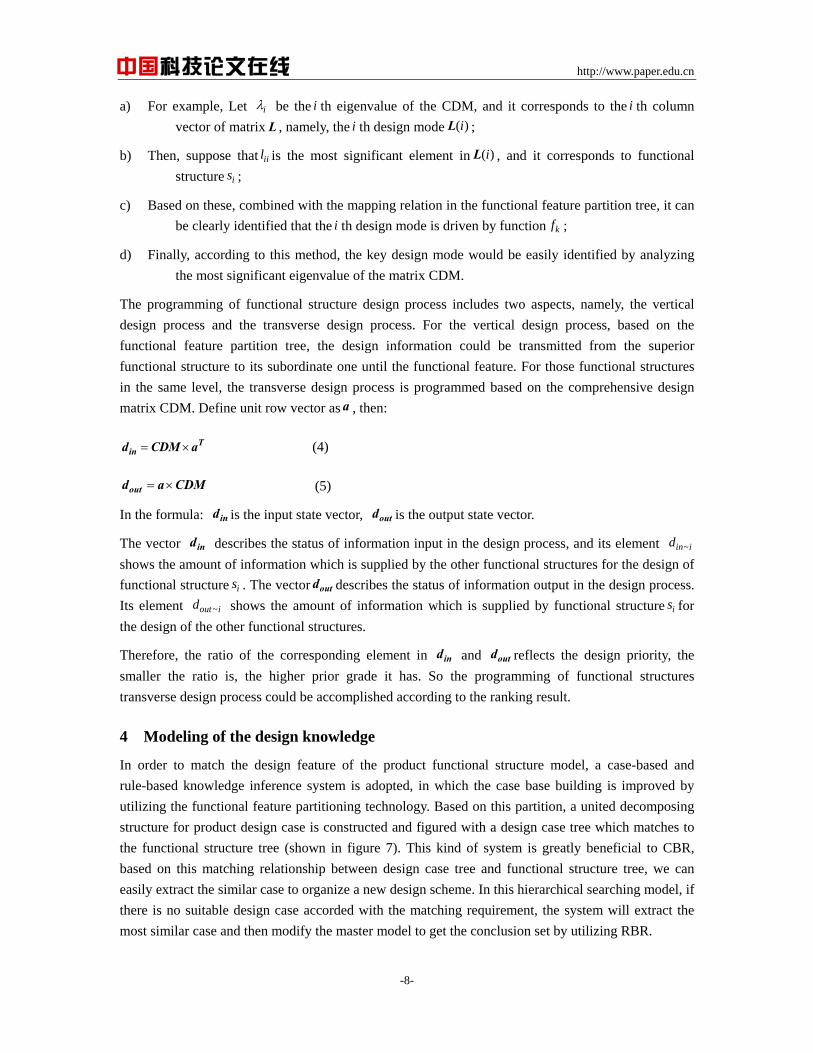
a) For example, Let i be the i th eigenvalue of the CDM, and it corresponds to the i th column
vector of matrix L , namely, the i th design mode ( )iL ;
b) Then, suppose that iil is the most significant element in ( )iL , and it corresponds to functional
structure is ;
c) Based on these, combined with the mapping relation in the functional feature partition tree, it can
be clearly identified that the i th design mode is driven by function kf ;
d) Finally, according to this method, the key design mode would be easily identified by analyzing
the most significant eigenvalue of the matrix CDM.
The programming of functional structure design process includes two aspects, namely, the vertical
design process and the transverse design process. For the vertical design process, based on the
functional feature partition tree, the design information could be transmitted from the superior
functional structure to its subordinate one until the functional feature. For those functional structures
in the same level, the transverse design process is programmed based on the comprehensive design
matrix CDM. Define unit row vector as a , then:
Tind CDM a (4)
outd a CDM (5)
In the formula: is the input state vector, is the output state vector. ind outd
The vector describes the status of information input in the design process, and its element
shows the amount of information which is supplied by the other functional structures for the design of
functional structure
ind ~in id
is . The vector describes the status of information output in the design process.
Its element shows the amount of information which is supplied by functional structureoutd
~ioutd is for
the design of the other functional structures.
Therefore, the ratio of the corresponding element in and reflects the design priority, the
smaller the ratio is, the higher prior grade it has. So the programming of functional structures
transverse design process could be accomplished according to the ranking result.
ind outd
4 Modeling of the design knowledge
In order to match the design feature of the product functional structure model, a case-based and
rule-based knowledge inference system is adopted, in which the case base building is improved by
utilizing the functional feature partitioning technology. Based on this partition, a united decomposing
structure for product design case is constructed and figured with a design case tree which matches to
the functional structure tree (shown in figure 7). This kind of system is greatly beneficial to CBR,
based on this matching relationship between design case tree and functional structure tree, we can
easily extract the similar case to organize a new design scheme. In this hierarchical searching model, if
there is no suitable design case accorded with the matching requirement, the system will extract the
most similar case and then modify the master model to get the conclusion set by utilizing RBR.
-8-
http://www.paper.edu.cn 中国科技论文在线

The corresponding modeling driven mechanism can be established based on the combination of
product functional structure model and design knowledge inference engine (shown in Figure 7), the
concrete steps are as follow:
Figure 7: Knowledge inference engine and modeling driven mechanism
Step 1: Construct the knowledge unit of the functional structure according to the product functional
structure model, then establish the knowledge unit library by integrating these knowledge units at all
levels through design knowledge inference;
Step 2: The overall function object sends message to trigger the branch function object who judges the
operation to analyze and calculate the mapping relationship between product functions and structures,
and then select the functional structure object which meets the searching requirements;
Step 3: The functional structure object sends message to trigger the knowledge unit library that
conducts the operation to extract and apply the corresponding design information into the constraint
solving, and then determine the design parameters which meet the constraint requirement;
Step 4: Utilize the secondary development module of CAD software system such as Catia/GII and
Pro/Toolkit. Then, carry on parametric designs of the functional structure design module under
VC++/VB development environment, repeat the above steps until the completion of all the design
modules.
5 Case Study
Take the cylinder block of automobile engine for example, as shown in Figure 8. There are different
types of rib reinforcements, cleaning holes, bearing saddle bores, water jacket and oil channels
distributed within the structure. In addition, the different types of horizontal and vertical baffle plates
in engine, which, together with different types of constraints existing among the features, makes the
spatial relationship quite complicated.
-9-
http://www.paper.edu.cn 中国科技论文在线

cylinder crankcase
Cylinder block
water/oil pump rib reinforcement
oil channel
water jacket
exhaust passage cleaning hole
Figure 8: Cylinder block of automobile engine
Through the analysis of its function, the block functions can be partitioned into 3 types, namely, basic
functions, auxiliary functions and other functions. Basic function refers to the original function
assumed in engine operating principle; auxiliary function coordinates with basic function and ensures
its normal operation; other functions mainly refer to adjustive functions designed to meet
manufacturing requirement other than basic function and auxiliary function. Figure 9 shows the
functional feature partition of the cylinder block at its first level.
Based on the partitioning result, the structure design matrix DSM1 and DSM2 can be developed by
the method presented in section 3. The comprehensive design matrix CDM can then be obtained by
synthesizing the two matrices:
1.000 0.099 0.000 0.150 0.000 0.000 0.000
0.099 1.000 0.005 0.064 0.000 0.000 0.000
0.050 0.005 1.000 0.015 0.000 0.021 0.000
0.155 0.069 0.000 1.000 0.000 0.000 0.000
0.005 0.015 0.000 0.000 1.000 0.000 0.000
0.000 0.005 0.036 0.000 0
CDM =
.005 1.000 0.000
0.005 0.000 0.000 0.000 0.000 0.000 1.000
The key design mode can be identified through the eigenvalue analysis of the comprehensive design
matrix.
As shown in Table one, the key eigenvalue is 1.216. The significant elements of its corresponding
eigenvector are -0.616 and -0.588, which correspond to cylinder crankcase and oil channel
respectively. Finally, through the mapping relationship between function and structure we can
conclude that the key design mode is driven by the source function.
-10-
http://www.paper.edu.cn 中国科技论文在线

Figure 9: The functional feature partition of cylinder block
Table 1 Result of eigenvalue analysis
Eigen
value
Eigen
vector
Functional
structure Branch function
1.000 -0.616 1s : crankcase 1f :source
1.216 -0.459 2s :water pump 2f : linkage
0.843 -0.198 3s :water jacket 3f : cooling
0.942 -0.588 4s :oil channel 4f :lubricating
0.971 -0.046 5s :rib reinforcement 5f :intensifying
1.027 -0.045 6s :cleaning hole 6f : cleaning
0.999 -0.142 7s :exhaust passage 7f : airing
Then, the input/output state vector can be obtained based on the comprehensive design matrix,
according to the ranking result of in outd d , we can easily accomplish the planning of the design
process. Table 2 shows the planning results.
Table 2 Planning results of design process
Information 1s 2s 3s 4s 5s 6s 7s
ind 2.49 2.34 2.18 2.45 2.04 2.09 2.10
outd 2.71 2.39 2.08 2.46 2.01 2.04 2.00
in outd d 0.92 0.98 1.05 0.99 1.01 1.02 1.05
Planning 1s 2s 4s 5s 6s 3s 7s
Finally, the cylinder block can be divided into 4 layers, which includes totally 252 functional feature
modules. The design parameters and rules of each functional feature could be represented with frames
based on the functional feature partition tree. Through knowledge acquisition, it adopts a uniform
expression to conduct rule representation as follow:
Other functions
Auxiliary functions
Basic functions
2 :f linkaging
1 :f source
6 :
3 :f cooling
4 : f cleaningf lubricating
5 :f intensifying
7 :f airingwater/oil pump 2:s
1:s crankcase
3:s water
jacket
4 :s oil
channel
6 :s cleaning
hole
7 :s exhaust
passage
rib
-11-
http://www.paper.edu.cn 中国科技论文在线

Rule (RuleNo, <Conclusion expression>, [CondNo], [ConcluNo], Reliability)
Cond (CondNo, <Condition expression>).
Then, all of the rules are compiled into fact base and rule base (shown in table3 and table4), which are
expressed by utilizing the object-oriented methods:
Class Rule {
Private: // Rule’s attribution
Char RuleNo [10]; // Rule number
Char CondNo [100]; // Condition number
Char ConcluNo [100]; // Conclusion number
Float Reliability; // Rule confidence
Public: // Rule inference
Rule (RuleNo [10], CondNo [100], ConcluNo [100], Reliability); //Initialization
~Rule ( ); // Destructor function
Void SelectRule (CondNo [500]); //Calling method}
During the operation of the system, users first determine the design requirements and objectives. Then
the system makes use of CBR to perform model retrieval, and makes inference using the expert
system’s equation for similarity computing. The main model that best meets the requirements is
extracted and RBR is then used to modify this model. Finally, the system generates a command stream
file based on the inferred parameter values, submits it to the background program for modeling and
displays the results on the user interface. Figure10 shows the design process and the software
implementation of the cylinder block.
Table 3 Fact base
FactNo Fact description
1 Engine type: A=“Liner Gasoline”
2 Cylinder diameter: D= diameter
3 MainDia=(0.65~0.7)*D
4 ConDia=(0.60~0.65)*D
5 MainDia/ConDia[a, b]
6 Accord with the crank design criterion
┇ ┇
Table 4 Rule base
RuleNo CondNo CondNo … ConcluNo Reliability
R0001 1 2 / 3、4 0.90
R0002 5 / / 6 1
┇ ┇ ┇ ┇ ┇ ┇
-12-
http://www.paper.edu.cn 中国科技论文在线

Figure 10: The practical design example of the cylinder block
4 Conclusions
This paper presents a method of constructing the modular design knowledge model for complex
structural components. Firstly, the initial conceptual design module of the complex structural
component is decomposed based on its function. Secondly, the comprehensive design matrix is
obtained. With this matrix, the feature description and system modelling on the coupling relation
between modules are accomplished during the product development process. According to the
correlation analysis, the key design mode can be clearly identified. At the same time, the design
process of functional structures can also been designed and programmed. Finally, the design
knowledge can be represented by a set of frames based on the functional feature partition tree. The
method has been used in a case study of the cylinder block, in which the positive design idea runs
through the whole design process. It appears that the application of this method can improve
efficiency in the product development process for complex structural components.
References
[1] REZAYAT M. Knowledge-based product development using XML and KCs [J]. Computer Aided Design, 2000,
32,pp. 299-309
[2] Pahng G F, HA S, PARk S. A design knowledge management framework for active design support
[C].Proceedings of DETC’99, ASME Design Engineering Technical Conferences,Las Vegas,1999,pp. 9023-9031
[3] TROXLER P. Knowledge technologies in engineering design [C].Proceedings of 7th International Design
Conference, Faculty of Mechanical Engineering and Naval Architecture,Dubrovnik,2002,pp. 429-434
[4] FINGER S, DIXON JR. A review of research in mechanical engineering design [J].Research in Engineering
Design,1989,1,pp. 51-67
[5] G. BRUNETTI, B. GOLOB. A feature-based approach towards an integrated product model including
conceptual design information [J].Computer-Aided Design, 2000, 32,pp. 877-887
[6] HOU LIANG, TANG RENZHONG, XU YANSHEN, ZHANG WEI. Research on knowledge base system of
-13-
http://www.paper.edu.cn 中国科技论文在线

-14-
flexible modular design for mechanical products[J]. Journal of Zhejiang University, 2004, 38(1) ,pp.44-47
[7] ROBERT B. STONE, KRISTIN L. WOOD, RICHARD H. CRAWFORD. Using quantitative functional models
to develop product architectures[J]. Design Studies, 2000, 21(3),pp. 239-260
[8] GAO FEI, XIAO GANG, PAN SHUANGXIA, CHEN JIUJUN, ZHANG YUANMING. Method of product
function module partition [J].Chinese Journal of Mechanical Engineering, 2007, 43(5),pp. 29-35
[9] GUNNAR ERIXON, ALEX VON YXKULL, ANDERS ARNSTROM. Modularity-the basis for product and
factory reengineering [C].Annals of the CIRP, 1996, 45(1),pp. 1-6
[10] P. GU, M. HASHEMIAN, S. SOSALE. An integrated modular design methodology for life-cycle engineering,
Annals of the CIRP [C].1997, 46(1),pp. 71-74
[11] T.L. SAATY. The analytic hierarchy process [M]. New York: McGraw-Hill,1980
Author Brief Introduction:
Li Baotong P.H.D. Candidate State Key Laboratory for Manufacturing Systems Engineering
School of Mechanical Engineering Xi'an Jiaotong University Xi'an 710049, China E-mail: [email protected]
http://www.paper.edu.cn 中国科技论文在线