Embed Size (px)
Citation preview

A1.5 Two-channel Power AmplifierUser Manual

Dear Valued Customer,
We are honored that you chose the A1.5 Power Amplifier for your audio system. Our team devoted every effort to design and manufacture this highest-quality versatile and future-proof product and is proud to present it to you. We wish you hours of enjoyment from your music collection with the A1.5 Power Amplifier installed in your system.
Before you embark on your musical journey, we kindly request your special attention regarding the information contained in this manual. The A1.5, as you will discover in the following pages, is a Swiss precision product designed for ultimate performance and flexibility. However, reaching sonic excellence from your audio system requires your unit to be set up and operated correctly and this what this manual is all about. If you have any questions or require assistance, please don't hesitate to contact your authorized dealer.
We hope you will enjoy your A1.5 for many years to come.
The Concert has just begun...
Cossy F.
Heeb T.

Table of contents 1 Product highlights............................................................................................................................................................... 7
1.1 Unmatched flexibility................................................................................................................................................. 8 1.1.1 Operation modes............................................................................................................................................... 8 1.1.2 Feedback control............................................................................................................................................... 9 1.1.3 Gain control...................................................................................................................................................... 9 1.1.4 ExactBias.......................................................................................................................................................... 9
1.2 Advanced monitoring circuit...................................................................................................................................... 10 1.2.1 Power monitoring............................................................................................................................................ 10 1.2.2 Temperature monitoring.................................................................................................................................. 10
1.3 Mechanical construction............................................................................................................................................ 10 1.4 Modular architecture and slot-in boards..................................................................................................................... 10
1.4.1 Monaural analog inputs: ANALOG_IN board...................................................................................................... 11 1.4.2 Firmware update and control: CONTROL board................................................................................................... 11
1.5 Power supply........................................................................................................................................................... 11 2 Before use........................................................................................................................................................................ 12
2.1 Package content....................................................................................................................................................... 12 2.2 Safety notice............................................................................................................................................................ 13 2.3 Mains supply............................................................................................................................................................ 13 2.4 Transport and packaging.......................................................................................................................................... 14 2.5 Cleaning your unit.................................................................................................................................................... 14 2.6 Maintenance and service........................................................................................................................................... 14
3 Installation....................................................................................................................................................................... 15 3.1 Unpacking............................................................................................................................................................... 15 3.2 Unit positioning........................................................................................................................................................ 15 3.3 Connections.............................................................................................................................................................. 16
3.3.1 CONTROL board............................................................................................................................................... 18 3.3.2 ANALOG_IN board........................................................................................................................................... 19
3.4 Power cord receptacle and voltage selection............................................................................................................... 19 3.5 Amplifier modes....................................................................................................................................................... 20
3.5.1 Stereo mode.................................................................................................................................................... 20 3.5.2 Bridge mode................................................................................................................................................... 20 3.5.3 Monaural mode............................................................................................................................................... 21 3.5.4 Passive bi-amplification mode........................................................................................................................... 21 3.5.5 Active bi-amplification mode............................................................................................................................ 22 3.5.6 Daisy-chain mode............................................................................................................................................ 22
4 Operation......................................................................................................................................................................... 24 4.1 Front panel controls.................................................................................................................................................. 24
4.1.1 Front panel..................................................................................................................................................... 24 4.1.2 Front face pushbuttons..................................................................................................................................... 24
4.2 Operating modes...................................................................................................................................................... 25 4.2.1 Normal mode.................................................................................................................................................. 25 4.2.2 Shortcuts mode................................................................................................................................................ 27 4.2.3 Menu mode..................................................................................................................................................... 29
4.3 Configuration........................................................................................................................................................... 32 4.3.1 A1.5 configuration menu items......................................................................................................................... 32
Rev 1.0 A1.5 User Manual 5
4.3.1.1 AUDIO SETTINGS..................................................................................................................................... 32 4.3.1.2 DISPLAY SETTINGS................................................................................................................................... 33 4.3.1.3 SHORTCUTS............................................................................................................................................ 34 4.3.1.4 FACTORY SETTINGS.................................................................................................................................. 35 4.3.1.5 INSTALLED OPTIONS................................................................................................................................ 36 4.3.1.6 NETWORK............................................................................................................................................... 37
5 Firmware update.............................................................................................................................................................. 38 5.1 Preparing the USB flash-drive................................................................................................................................... 38 5.2 Updating the unit's firmware.................................................................................................................................... 38 5.3 Emergency firmware update procedure...................................................................................................................... 39
6 Troubleshooting................................................................................................................................................................ 40 7 Specifications.................................................................................................................................................................... 41
6 A1.5 User Manual Rev 1.0
1 Product highlightsCH products are meticulously designed and manufactured in Switzerland by CH Precision Sàrl. Our engineers put together all their know-how, expertise and ingeniousness to bring you the A1.5, a top performances future-proof modular 2-channel power amplifier with Ethernet control capabilities and USB flash-drive firmware upgradability. Like all CH Precision products, the A1.5 is highly versatile: 5 configuration are available with the A1.5: stereo mode requiring a single A1.5 and monaural, bridge mode, active and passive bi-amplification modes requiring a pair of power amplifiers.
For increased flexibility, the A1.5 also provides two unique features: the global versus local feedback ratio and gain adjustments. The amount of global feedback in the amplifying loop of each channel can be adjusted to best match virtually every loudspeaker on the market. The amplifier gain can also be adjusted over a 24 dB range in 0.5 dB steps. This also greatly helps in matching the output level of the preamplifier, the efficiency of the connected loudspeakers and the listening room. Three standard input are available (balanced XLR, single-ended RCA and BNC). Unbalanced inputs can be configured as high impedance inputs, or a 300 Ω load can be engaged. A pass-through XLR line-level output is also provided for daisy-chaining multiple CH amplifiers.
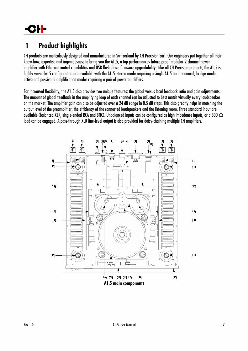
A1.5 main components
Rev 1.0 A1.5 User Manual 7
(1) Output coil for HF immunity(2) Custom Argento Audio speaker terminals(3) Monaural analog input boards (each A1.5 can be equipped with 1 or 2 such boards)(4) Standby fuse(5) Mains voltage selector(6) Mains power switch(7) Mains filter(8) IEC C20 power cord receptacle(9) Power fuse(10) USB (firmware update) and ethernet RJ-45 (control) board(11) Adjustment shafts(12) Power supply regulation boards(13) Heatsink-mounted monaural amplifier boards(14) Heatsink-mounted rectifying diode bridges(15) User interface buttons(16) Custom rectifying capacitors(17) Main analog star-ground oxygen-free copper plate(18) Custom standby transformer (ensures green mode Standby)(19) AMOLED display (on front panel)(20) Custom high power transformer
1.1 Unmatched flexibility
The A1.5 offers unmatched system integration features. Not only does it provide multiple modes of operation (stereo, monaural, bridge and active or passive bi-amplification) but it also provides adjustments to match speaker impedance and sensitivity through feedback and gain controls. The operating modes are user-selectable either from the A1.5 amplifier's front panel or from the CH Control app running on a tablet. In addition, multiple CH amplifiers can be daisy-chained for ultimate performance in multi-amplification systems.
1.1.1 Operation modes
The A1.5 integrates two channels of amplification and can be fitted with a single or two input boards. When fitted with a single input board, two power amplifier units are required (one per channel) and the pair provides the following modes of operation:
• Bridge mode: In this mode, each A1.5 operates as a very high power mono amplifier and can deliver up to 550 Watts
under 8 Ohms. Bridge mode is optimal for high impedance speakers in large rooms, requiring large voltage swings.
• Monaural mode: In this mode, the entire power supply is dedicated to a single amplification channel and each A1.5 unit
can deliver up to 700 Watts under 1 Ohm. It is optimal for low impedance speakers, requiring large amount of current.
• Passive bi-amplification mode: Used with loudspeakers fitted with multiples sets of terminals. In this mode, each A1.5
operates its two channels of amplification in parallel, fed from the same input signal. Each channel drives a different set of loudspeaker terminals. Feedback ratio and gain can be adjusted independently for each channel to best match the
8 A1.5 User Manual Rev 1.0
individual speaker sections. In Passive Bi-Amplification mode, each channel can deliver 150 Watts under 8 Ohms.
By adding a second input board, the A1.5 provides the following additional operating modes:
• Stereo mode: In stereo mode, each amplification stage is driven by its dedicated input board and the amplifier operates
as a standard stereo power amplifier. Feedback and gain settings are replicated on both channels of amplification and the A1.5 can deliver up to 2x 150 Watts under 8 Ohms. It is the configuration used when a single A1.5 drives a pair of speakers.
• Active bi-amplification mode: As per stereo mode, active bi-amp mode links each amplification stage to its dedicated
input board. Feedback and gain can however be adjusted individually for each channel in order to best match the requirements of each driver. An active external crossover, usually fitted between the preamplifier (such as the CH Precision's L1) and the A1.5, is generally used to split the signal into different frequency bands. In the Active Bi-Amplification mode, each A1.5 can deliver up to 2x 150 Watts under 8 Ohms.
1.1.2 Feedback control
One of CH range of power amplifier's most unique feature is its user controllable feedback. This feature provides control over the ratio between global and local feedback applied in the A1.5's amplification stage. Global feedback takes a portion of the output signal after the power stage and feeds it back to the input of the amplifier. This ensures a very low output impedance and low distortion figures. Local feedback, on the other hand, does not include the output stage and lets the latter operate in open loop mode. This favors small signal details and timing. As a rule of thumb, a higher ratio of global feedback is preferred for grip and control in the low frequencies whereas a lower ratio is preferred for speed and details in the high frequencies. This rule is however not absolute as each speaker and crossover are different and we highly recommend to experiment to find the best match with the connected loudspeakers, especially if the A1.5 is driving a complete full bandwidth loudspeaker. In multi-amplification systems, different feedback settings are commonly used for the various loudspeaker sections opening a whole new level of performance. We recommend to start with pure local feedback and increase the global feedback until the bass are tight enough to your personal taste. Feedback settings can be adjusted on the fly from the A1.5's front panel or from the CH Control app.
1.1.3 Gain control
The A1.5 provides an integrated gain control with a 24 dB range in 0.5 dB steps. This gain control allows an optimal matching of the speaker sensitivity, room size, and preamplifier output level. In multi-amplification systems it can be used to match the sensitivity of the individual speaker sections. Gain can be adjusted on the fly from the A1.5's front panel or from the CH Control app.
1.1.4 ExactBias
The A1.5 features an advanced bias control circuitry called ExactBias that not only Counteracts the effect of slow temperature variations, but also accurately takes into account all the dynamic aspects induced by transients in the musical content.
Rev 1.0 A1.5 User Manual 9
1.2 Advanced monitoring circuit
1.2.1 Power monitoring
Each power amplifier board is equipped with a DSP that monitors the instantaneous output voltage and current delivered to the loudspeaker. Both values are sampled at around 100 kHz, ensuring peak values are properly detected. DSP monitoring has several purposes: to give the user a feedback on the peak power delivered to the loudspeakers and to detect and act in case of a malfunction such as a short-circuit or amplifier damage.
1.2.2 Temperature monitoring
The DSPs also monitor the temperature of both the power transistors and the heatsinks. If the temperature gets excessive, the A1.5will protect itself by turning itself off.
1.3 Mechanical construction
The A1.5 power amplifier is assembled from high-quality aluminum and steel elements with no visible screws on the front, top and side panels. The front panel, base, side panels and top cover are machined from aluminum. The power supply is based on a fully shielded 1'700 VA toroidal transformer and ultra low ESR rectifying capacitors sitting in the central position of the unit. The area where the air flows to cool down the amplifier is hermetically sealed from the rest of the A1.5, ensuring the electronic circuitry is protected from gradually gathering dust. Pin assembly of all chassis elements provides smooth joints between elements while screws every 6cm ensures protection against electromagnetic interference. First class mechanical and chemical surface treatments provide the luxury finish of the A1.5.
Four steel feet support the unit. Each foot ends with a elastomer ring to sit on delicate surfaces but is also equipped with a height adjustable steel spike to fine tune the positioning of the unit. Horizontal adjustment is done with the provided screwdriver through the four adjustment shafts accessible from the top of the unit. In addition to providing convenient horizontal adjustment from the top of the unit, the shafts also serve as vibration evacuation channels for stacked units.
Special shaft covers (stacking covers) are provided to interface with the spikes of a stack of units. Any vibration from the upper unit is transmitted by the shaft cover to the shaft of the lower unit and from there to the lower unit's feet or spikes, forming a privileged path for vibrations evacuation. Support discs are provided and should be placed between the spike of the bottom unit and the piece of furniture holding the equipment.
1.4 Modular architecture and slot-in boards
The A1.5 benefits from a fully modular architecture. It features separated sections for power rails, analog and digital power supplies, front panel, signal routing and central host processor, monaural analog input boards and single channel amplification boards. This modular architecture combined with the USB plug for firmware update allows for easy servicing and upgrade should one section become faulty or obsolete.
The slot-in boards section consists of a vertically mounted backplane board with optional boards plugged into it. Optional boards provide audio functionality and connectivity to other equipment.
10 A1.5 User Manual Rev 1.0
1.4.1 Monaural analog inputs: ANALOG_IN board
The ANALOG_IN board features a user-selectable mono analog inputs on three different connectors: single-ended RCA, single-ended BNC and balanced XLR. Both the RCA and BNC inputs can be configured for high-impedance or 300 Ω load. In addition to its inputs, the ANALOG_IN board includes an XLR output providing a pass-through of the input signal used to daisy chain amplifiers.
1.4.2 Firmware update and control: CONTROL board
The CONTROL board is factory fitted to each A1.5. It features a USB port for software updates (using the provided USB flash-drive) and an Ethernet port for remote-controlling the unit over a standard Ethernet network.
1.5 Power supply
The power supply of the A1.5 is a linear supply with multiple independent local regulations. It is based on an overspecified magnetically shielded toroidal 1'700 VA mains transformer. A second toroidal transformer is used as standby transformer to ensure green standby mode, meeting the latest energy saving regulations. Both transformers have static shields between primary and secondary windings. They are mounted on a separate metal plate which is isolated from the main base plate by silent blocks.
Two 82'000μF electrolytic capacitors are used as reservoirs and filters to the main power supply. These capacitors exhibit exceptionally low ESR, huge current capability, very high speed and high capacitance, providing instantaneous response to current draw from the output stage.
Discrete (power-transistor and op-amp based) ultra low-noise regulators are used throughout the power supply system to ensure the purest low noise DC feed possible to the different sections. The input stages of the power section are also fully regulated to avoid any coupling distortion. A thick copper plate acts as signal ground star connection.
Input AC voltage to the power supply can be set to 100V, 115V or 230V AC to match your local mains voltage.
Rev 1.0 A1.5 User Manual 11
2 Before usePlease read this manual carefully before making connections or operating your A1.5. After reading this manual, please store it in an accessible place for future reference. If after reading this manual you feel unsure about how to make connections or how to operate the unit, please contact your authorized dealer for assistance.
2.1 Package content
Please make sure that the package content is complete. If not, please contact your authorized dealer. Your package should contain:
• Your A1.5 power amplifier with one or two input boards depending on what you ordered
• An IEC C19 power cord
• Four adjustment steel spikes
• A suction cup (used to unscrew the top covers)
• An accessory box containing:
◦ a spike adjustment screwdriver
◦ a Torx 10 screwdriver
◦ four stacking covers
◦ a USB flash-drive containing the latest CH Precision firmware.
◦ a set of four CH Support Discs
Please store the packaging for future use. Check your A1.5 for any apparent damage. In case of a damage, immediately contact your authorized dealer. If your A1.5 is cold due to transport, please let it warm up to room temperature before powering it up.
12 A1.5 User Manual Rev 1.0
2.2 Safety notice
Make sure to observe the following rules:
• Install your A1.5 power amplifier on a stable and sturdy base
• Do not install your A1.5 power amplifier near water
• Always handle the unit with care. The A1.5 power amplifier is very heavy, always have someone to help you when
moving it around
• Do not expose the unit to any kind of liquid
• Do not install in direct sunlight or near any heat sources such as radiators
• Do not install in a confined space and make sure sufficient air can flow around the unit, including under the unit.
• Never install your A1.5 power amplifier directly on a carpet or any soft material that could block off the ventilation
openings at the bottom of the unit
• Do not operate under high ambient temperature (>40°C) or with extremely high humidity
• Only use options and accessories specified or recommended by CH Precision
• Do not open the unit nor try to service it by yourself. Always refer to a qualified technician for service, maintenance or
upgrades. Failure to do so will void the unit's warranty
2.3 Mains supply
Make sure to use a 3 terminals (phase, neutral and earth) power cord with ground conductor. Make sure that the mains voltage selection of the unit matches the mains voltage in your location.
Make sure your A1.5 power amplifier is disconnected from the AC wall power in the following cases:
• When making connections (it is also recommended to disconnect the rest of the system from AC wall power)
• When cleaning the unit
• During thunderstorms
• When unused for a long period of time
Rev 1.0 A1.5 User Manual 13
2.4 Transport and packaging
The A1.5 power amplifier must always be stored in its original packaging for transportation. Doing so will ensure the optimal level of protection of your unit. Keep all the packaging material in a dry and clean place.
Besides, we recommend to remove the adjustment spikes and to put them into the A1.5 box (four holes in the bottom piece of foam) for transportation. Vibrations during transport may cause the adjustment spikes to move from their fully retracted position and you run the risk of scratching your rack if the spikes are not fully retracted when installing the unit.
2.5 Cleaning your unit
Use a soft, dry towel or cloth for cleaning. Never use any solvent or liquids as they may damage the surface treatment or penetrate inside the unit.
2.6 Maintenance and service
The A1.5 power amplifier contains no user serviceable parts. Do not try to open, modify or attempt any repair on your A1.5. This will void any warranty. Your A1.5 power amplifier must be serviced by a qualified technician in any of the following cases:
• The unit is not functioning properly
• The mains cable or the power cord receptacle is damaged
• The unit has been dropped to the floor or presents external damage
• The A1.5 power amplifier has been exposed to liquids (such as rain) or unknown substances
14 A1.5 User Manual Rev 1.0
3 Installation
3.1 Unpacking
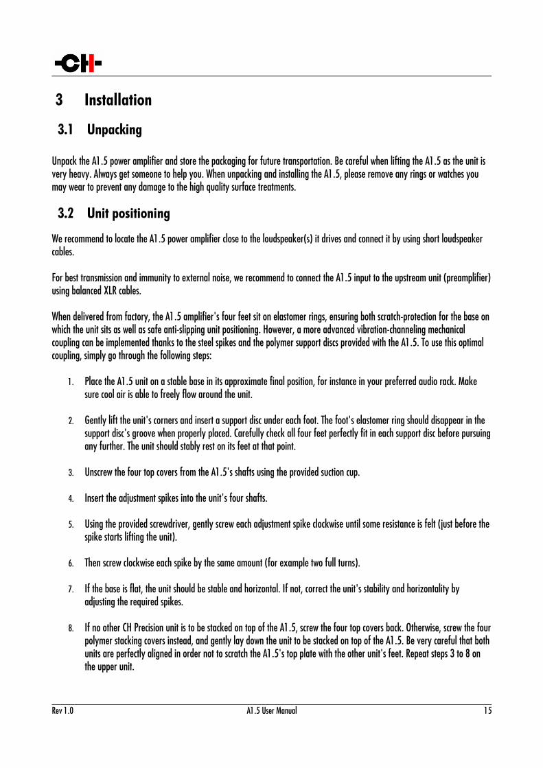
Unpack the A1.5 power amplifier and store the packaging for future transportation. Be careful when lifting the A1.5 as the unit is very heavy. Always get someone to help you. When unpacking and installing the A1.5, please remove any rings or watches you may wear to prevent any damage to the high quality surface treatments.
3.2 Unit positioning
We recommend to locate the A1.5 power amplifier close to the loudspeaker(s) it drives and connect it by using short loudspeaker cables.
For best transmission and immunity to external noise, we recommend to connect the A1.5 input to the upstream unit (preamplifier)using balanced XLR cables.
When delivered from factory, the A1.5 amplifier's four feet sit on elastomer rings, ensuring both scratch-protection for the base onwhich the unit sits as well as safe anti-slipping unit positioning. However, a more advanced vibration-channeling mechanical coupling can be implemented thanks to the steel spikes and the polymer support discs provided with the A1.5. To use this optimal coupling, simply go through the following steps:
1. Place the A1.5 unit on a stable base in its approximate final position, for instance in your preferred audio rack. Make sure cool air is able to freely flow around the unit.
2. Gently lift the unit's corners and insert a support disc under each foot. The foot's elastomer ring should disappear in the support disc's groove when properly placed. Carefully check all four feet perfectly fit in each support disc before pursuingany further. The unit should stably rest on its feet at that point.
3. Unscrew the four top covers from the A1.5's shafts using the provided suction cup.
4. Insert the adjustment spikes into the unit's four shafts.
5. Using the provided screwdriver, gently screw each adjustment spike clockwise until some resistance is felt (just before thespike starts lifting the unit).
6. Then screw clockwise each spike by the same amount (for example two full turns).
7. If the base is flat, the unit should be stable and horizontal. If not, correct the unit's stability and horizontality by adjusting the required spikes.
8. If no other CH Precision unit is to be stacked on top of the A1.5, screw the four top covers back. Otherwise, screw the fourpolymer stacking covers instead, and gently lay down the unit to be stacked on top of the A1.5. Be very careful that bothunits are perfectly aligned in order not to scratch the A1.5's top plate with the other unit's feet. Repeat steps 3 to 8 on the upper unit.
Rev 1.0 A1.5 User Manual 15
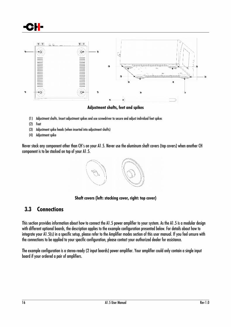
Adjustment shafts, feet and spikes
(1) Adjustment shafts. Insert adjustment spikes and use screwdriver to secure and adjust individual feet spikes(2) Feet(3) Adjustment spike heads (when inserted into adjustment shafts)(4) Adjustment spike
Never stack any component other than CH's on your A1.5. Never use the aluminum shaft covers (top covers) when another CH component is to be stacked on top of your A1.5.
Shaft covers (left: stacking cover, right: top cover)
3.3 Connections
This section provides information about how to connect the A1.5 power amplifier to your system. As the A1.5 is a modular design with different optional boards, the description applies to the example configuration presented below. For details about how to integrate your A1.5(s) in a specific setup, please refer to the Amplifier modes section of this user manual. If you feel unsure with the connections to be applied to your specific configuration, please contact your authorized dealer for assistance.
The example configuration is a stereo-ready (2 input boards) power amplifier. Your amplifier could only contain a single input board if your ordered a pair of amplifiers.
16 A1.5 User Manual Rev 1.0
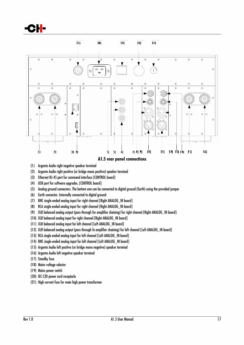
A1.5 rear panel connections(1) Argento Audio right negative speaker terminal(2) Argento Audio right positive (or bridge mono positive) speaker terminal(3) Ethernet RJ-45 port for command interface [CONTROL board](4) USB port for software upgrades. [CONTROL board](5) Analog ground connectors. The bottom one can be connected to digital ground (Earth) using the provided jumper(6) Earth connector. Internally connected to digital ground(7) BNC single-ended analog input for right channel [Right ANALOG_IN board](8) RCA single-ended analog input for right channel [Right ANALOG_IN board](9) XLR balanced analog output (pass-through for amplifier chaining) for right channel [Right ANALOG_IN board](10) XLR balanced analog input for right channel [Right ANALOG_IN board](11) XLR balanced analog input for left channel [Left ANALOG_IN board](12) XLR balanced analog output (pass-through fo amplifier chaining) for left channel [Left ANALOG_IN board](13) RCA single-ended analog input for left channel [Left ANALOG_IN board](14) BNC single-ended analog input for left channel [Left ANALOG_IN board](15) Argento Audio left positive (or bridge mono negative) speaker terminal(16) Argento Audio left negative speaker terminal(17) Standby fuse(18) Mains voltage selector(19) Mains power switch(20) IEC C20 power cord receptacle(21) High current fuse for main high power transformer
Rev 1.0 A1.5 User Manual 17
3.3.1 CONTROL board
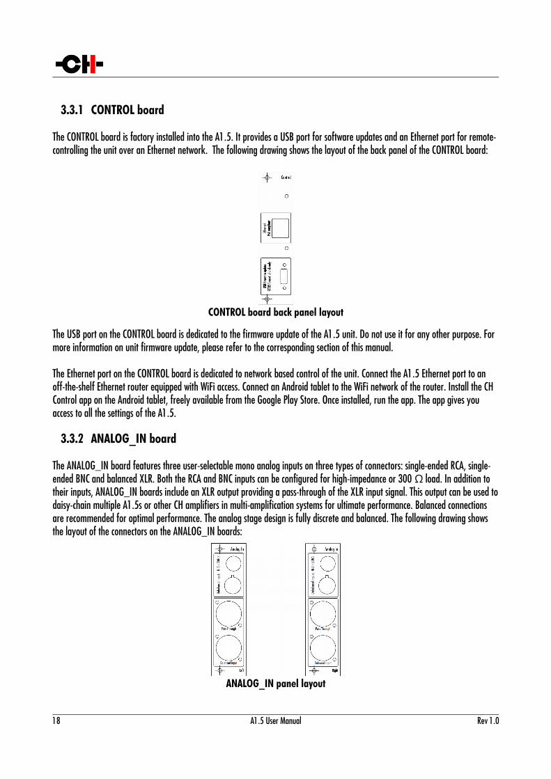
The CONTROL board is factory installed into the A1.5. It provides a USB port for software updates and an Ethernet port for remote-controlling the unit over an Ethernet network. The following drawing shows the layout of the back panel of the CONTROL board:
CONTROL board back panel layout
The USB port on the CONTROL board is dedicated to the firmware update of the A1.5 unit. Do not use it for any other purpose. For more information on unit firmware update, please refer to the corresponding section of this manual.
The Ethernet port on the CONTROL board is dedicated to network based control of the unit. Connect the A1.5 Ethernet port to an off-the-shelf Ethernet router equipped with WiFi access. Connect an Android tablet to the WiFi network of the router. Install the CH Control app on the Android tablet, freely available from the Google Play Store. Once installed, run the app. The app gives you access to all the settings of the A1.5.
3.3.2 ANALOG_IN board
The ANALOG_IN board features three user-selectable mono analog inputs on three types of connectors: single-ended RCA, single-ended BNC and balanced XLR. Both the RCA and BNC inputs can be configured for high-impedance or 300 Ω load. In addition to their inputs, ANALOG_IN boards include an XLR output providing a pass-through of the XLR input signal. This output can be used todaisy-chain multiple A1.5s or other CH amplifiers in multi-amplification systems for ultimate performance. Balanced connections are recommended for optimal performance. The analog stage design is fully discrete and balanced. The following drawing shows the layout of the connectors on the ANALOG_IN boards:
ANALOG_IN panel layout
18 A1.5 User Manual Rev 1.0
3.4 Power cord receptacle and voltage selection
Make sure that the voltage selection is set to the correct value with respect to the AC voltage in your location. Connect the IEC C19 power cord to the IEC C20 power cord receptacle and plug the power plug to an AC wall outlet only after all other connections were made.
If third-party power cords are used, make sure that the socket mating with the A1.5 is fully inserted and not able to move and create intermittent contacts due to its own weight.
3.5 Amplifier modes
This section describes the most standard setups in which one or multiple A1.5 amplifiers can be integrated into.
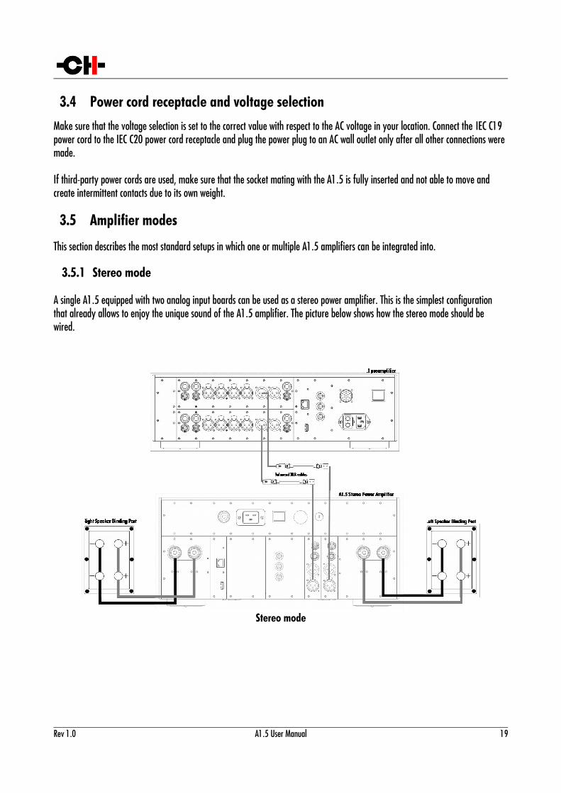
3.5.1 Stereo mode
A single A1.5 equipped with two analog input boards can be used as a stereo power amplifier. This is the simplest configuration that already allows to enjoy the unique sound of the A1.5 amplifier. The picture below shows how the stereo mode should be wired.
Stereo mode
Rev 1.0 A1.5 User Manual 19
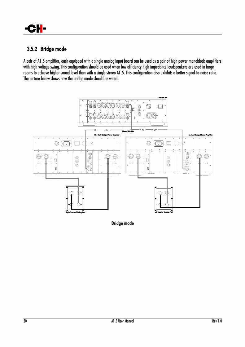
3.5.2 Bridge mode
A pair of A1.5 amplifier, each equipped with a single analog input board can be used as a pair of high power monoblock amplifierswith high voltage swing. This configuration should be used when low efficiency high impedance loudspeakers are used in large rooms to achieve higher sound level than with a single stereo A1.5. This configuration also exhibits a better signal-to-noise ratio. The picture below shows how the bridge mode should be wired.
Bridge mode
20 A1.5 User Manual Rev 1.0
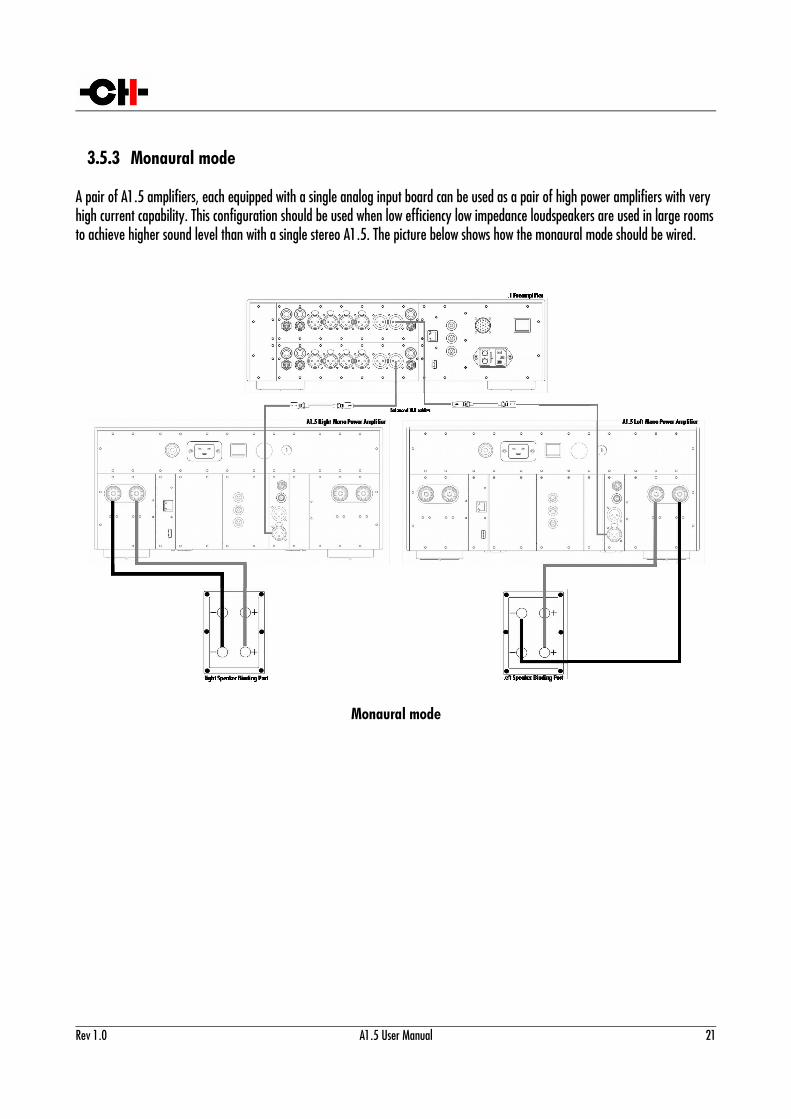
3.5.3 Monaural mode
A pair of A1.5 amplifiers, each equipped with a single analog input board can be used as a pair of high power amplifiers with very high current capability. This configuration should be used when low efficiency low impedance loudspeakers are used in large roomsto achieve higher sound level than with a single stereo A1.5. The picture below shows how the monaural mode should be wired.
Monaural mode
Rev 1.0 A1.5 User Manual 21
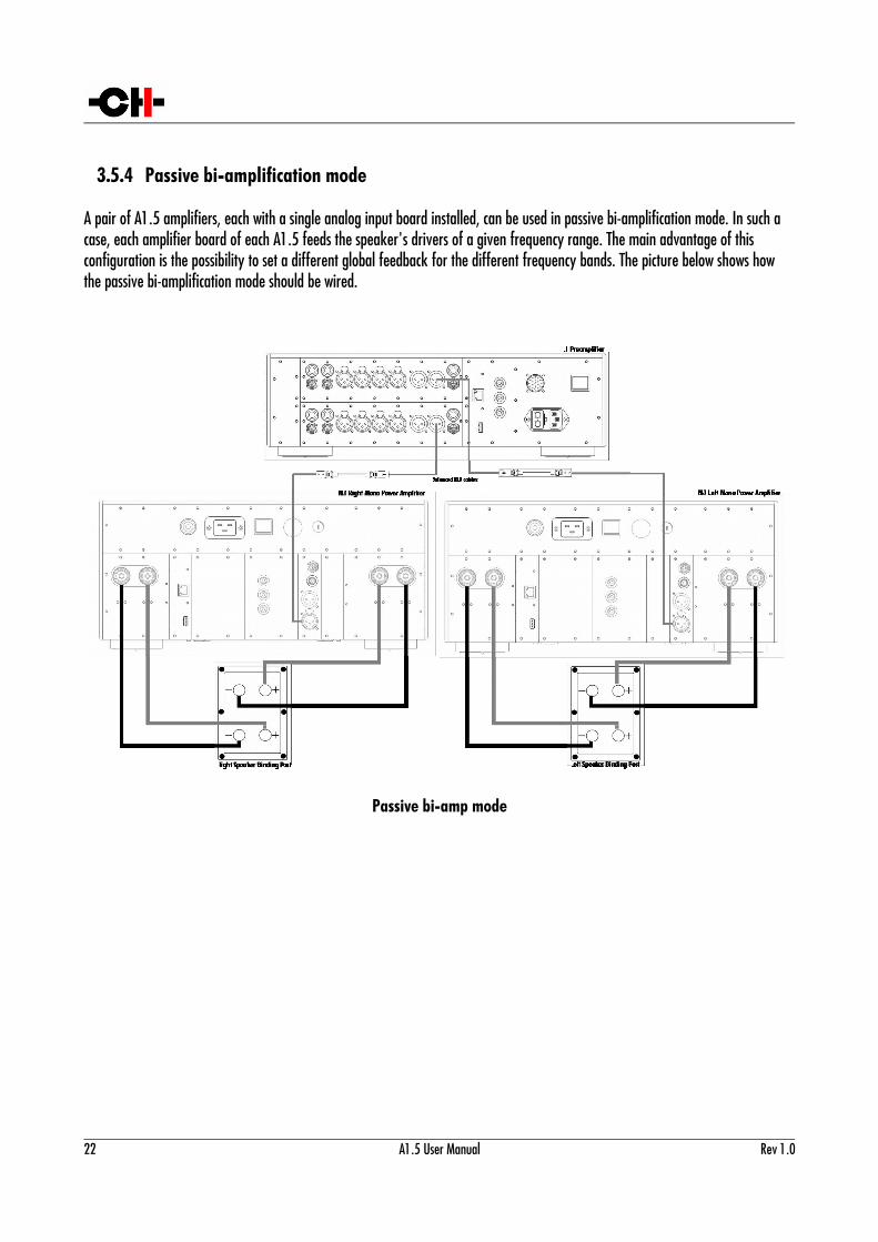
3.5.4 Passive bi-amplification mode
A pair of A1.5 amplifiers, each with a single analog input board installed, can be used in passive bi-amplification mode. In such a case, each amplifier board of each A1.5 feeds the speaker's drivers of a given frequency range. The main advantage of this configuration is the possibility to set a different global feedback for the different frequency bands. The picture below shows how the passive bi-amplification mode should be wired.
Passive bi-amp mode
22 A1.5 User Manual Rev 1.0
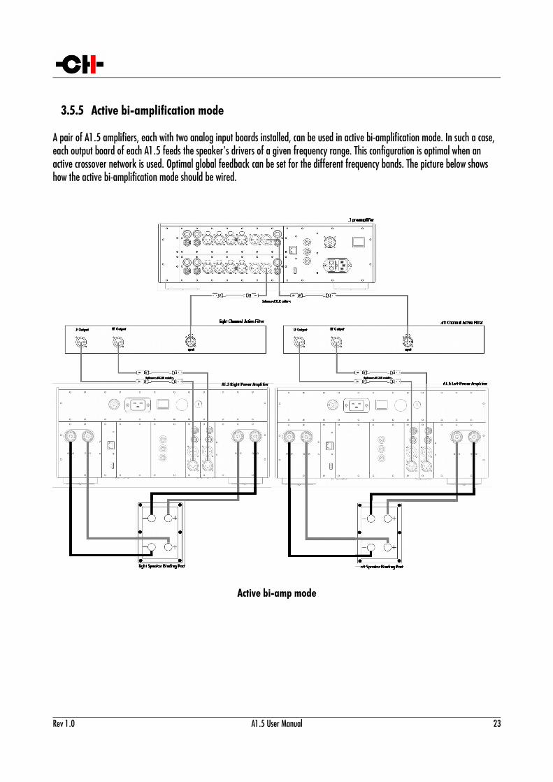
3.5.5 Active bi-amplification mode
A pair of A1.5 amplifiers, each with two analog input boards installed, can be used in active bi-amplification mode. In such a case, each output board of each A1.5 feeds the speaker's drivers of a given frequency range. This configuration is optimal when an active crossover network is used. Optimal global feedback can be set for the different frequency bands. The picture below shows how the active bi-amplification mode should be wired.
Active bi-amp mode
Rev 1.0 A1.5 User Manual 23
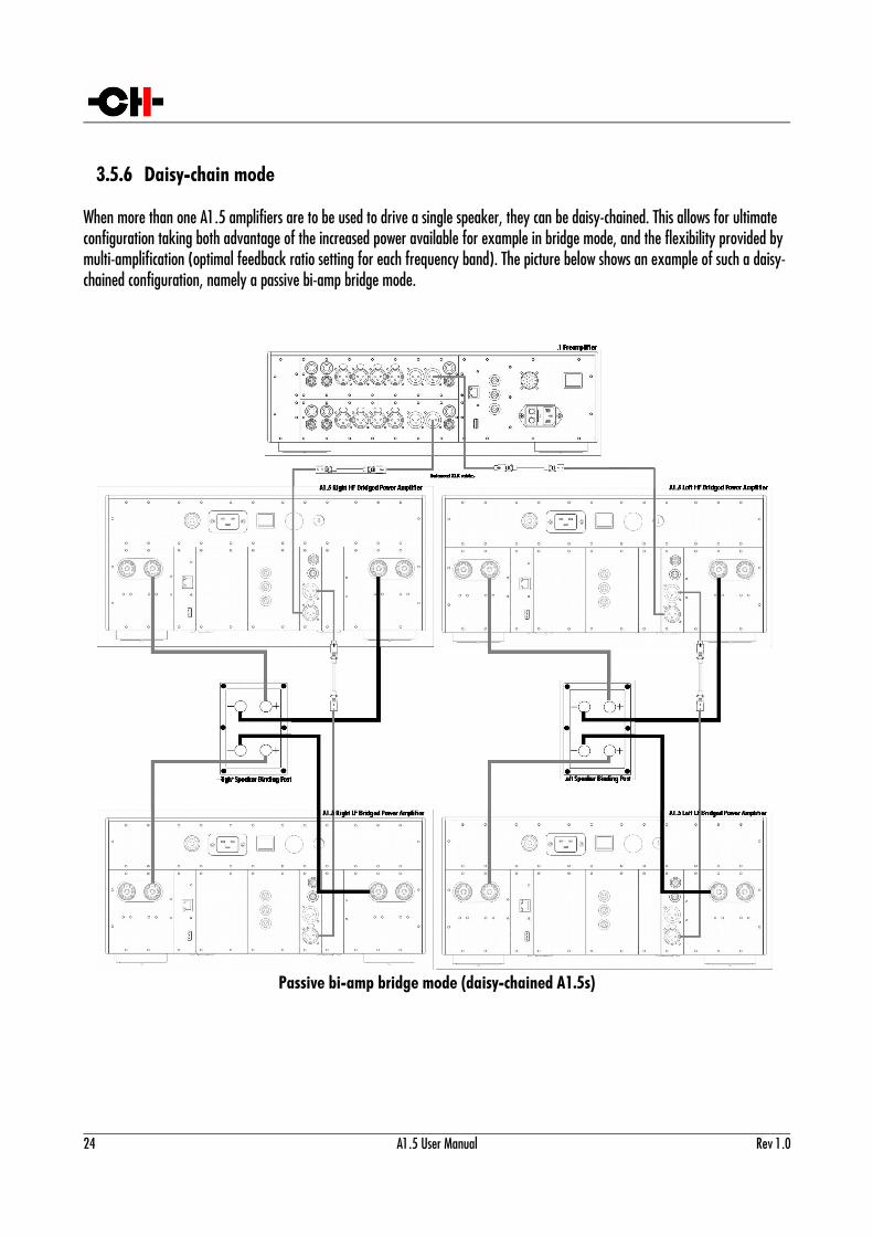
3.5.6 Daisy-chain mode
When more than one A1.5 amplifiers are to be used to drive a single speaker, they can be daisy-chained. This allows for ultimate configuration taking both advantage of the increased power available for example in bridge mode, and the flexibility provided by multi-amplification (optimal feedback ratio setting for each frequency band). The picture below shows an example of such a daisy-chained configuration, namely a passive bi-amp bridge mode.
Passive bi-amp bridge mode (daisy-chained A1.5s)
24 A1.5 User Manual Rev 1.0
4 OperationThe A1.5 power amplifier is operated either from the unit's front panel pushbuttons and display or from the CH Control app available on Android tablets. The tablet reflects the state of the unit settings and allows the user to adjust the settings on the fly, directly from the optimal listening position.
4.1 Front panel controls
4.1.1 Front panel
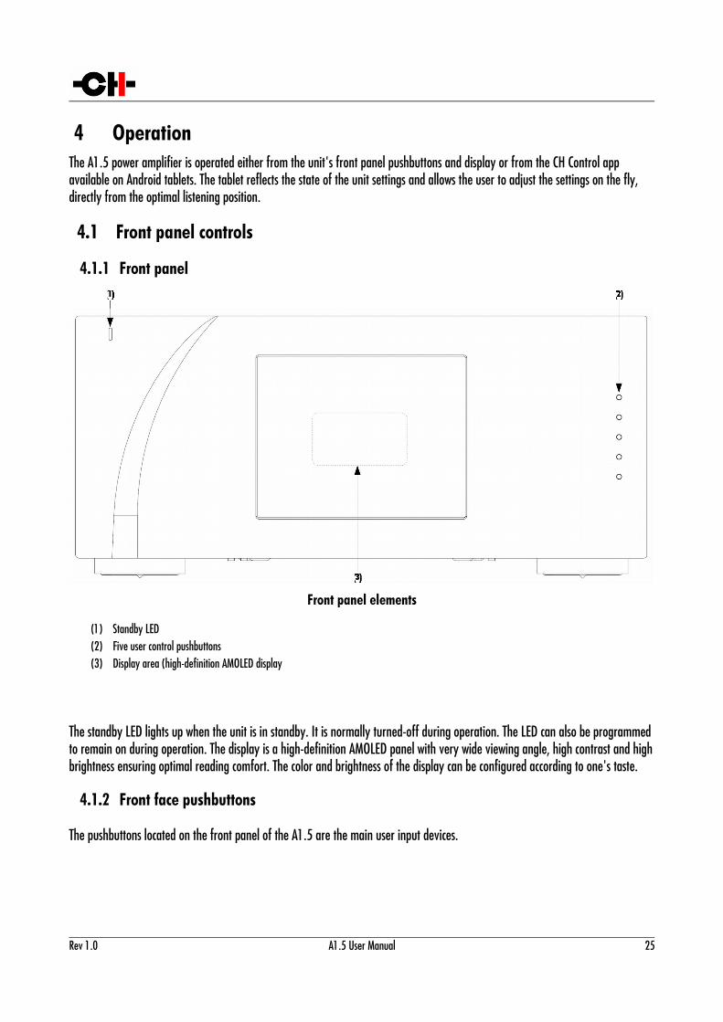
Front panel elements
(1) Standby LED(2) Five user control pushbuttons (3) Display area (high-definition AMOLED display
The standby LED lights up when the unit is in standby. It is normally turned-off during operation. The LED can also be programmedto remain on during operation. The display is a high-definition AMOLED panel with very wide viewing angle, high contrast and highbrightness ensuring optimal reading comfort. The color and brightness of the display can be configured according to one's taste.
4.1.2 Front face pushbuttons
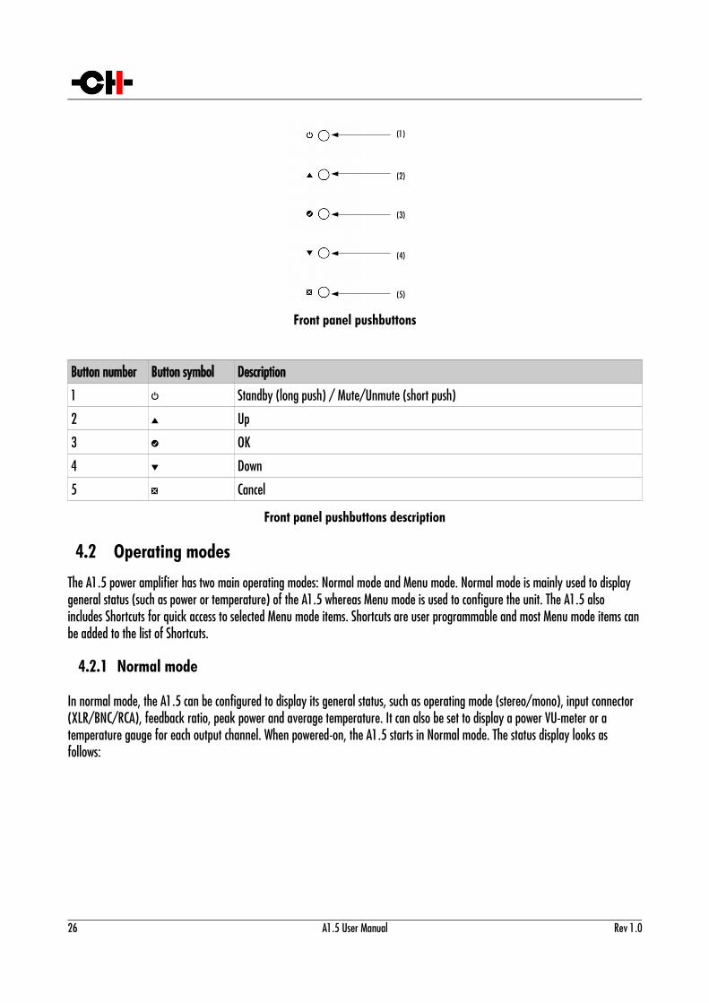
The pushbuttons located on the front panel of the A1.5 are the main user input devices.
Rev 1.0 A1.5 User Manual 25
Front panel pushbuttons
Button number Button symbol Description
1 S Standby (long push) / Mute/Unmute (short push)
2 N Up
3 R OK
4 O Down
5 Q Cancel
Front panel pushbuttons description
4.2 Operating modes
The A1.5 power amplifier has two main operating modes: Normal mode and Menu mode. Normal mode is mainly used to display general status (such as power or temperature) of the A1.5 whereas Menu mode is used to configure the unit. The A1.5 also includes Shortcuts for quick access to selected Menu mode items. Shortcuts are user programmable and most Menu mode items canbe added to the list of Shortcuts.
4.2.1 Normal mode
In normal mode, the A1.5 can be configured to display its general status, such as operating mode (stereo/mono), input connector (XLR/BNC/RCA), feedback ratio, peak power and average temperature. It can also be set to display a power VU-meter or a temperature gauge for each output channel. When powered-on, the A1.5 starts in Normal mode. The status display looks as follows:
26 A1.5 User Manual Rev 1.0
(2)
(3)
(4)
(5)
(1)
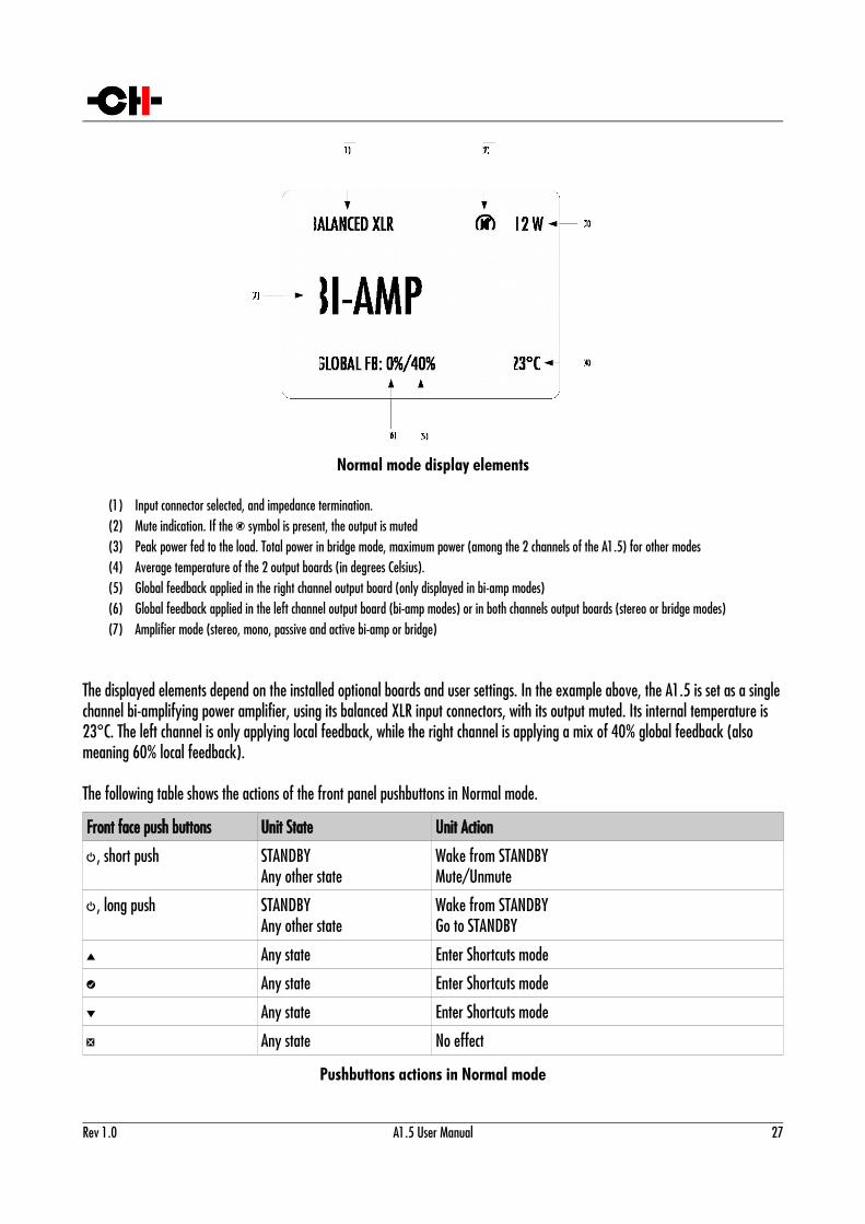
Normal mode display elements
(1) Input connector selected, and impedance termination.(2) Mute indication. If the 7 symbol is present, the output is muted(3) Peak power fed to the load. Total power in bridge mode, maximum power (among the 2 channels of the A1.5) for other modes(4) Average temperature of the 2 output boards (in degrees Celsius).(5) Global feedback applied in the right channel output board (only displayed in bi-amp modes)(6) Global feedback applied in the left channel output board (bi-amp modes) or in both channels output boards (stereo or bridge modes)(7) Amplifier mode (stereo, mono, passive and active bi-amp or bridge)
The displayed elements depend on the installed optional boards and user settings. In the example above, the A1.5 is set as a singlechannel bi-amplifying power amplifier, using its balanced XLR input connectors, with its output muted. Its internal temperature is 23°C. The left channel is only applying local feedback, while the right channel is applying a mix of 40% global feedback (also meaning 60% local feedback).
The following table shows the actions of the front panel pushbuttons in Normal mode.
Front face push buttons Unit State Unit Action
S, short push STANDBYAny other state
Wake from STANDBYMute/Unmute
S, long push STANDBYAny other state
Wake from STANDBYGo to STANDBY
N Any state Enter Shortcuts mode
R Any state Enter Shortcuts mode
O Any state Enter Shortcuts mode
Q Any state No effect
Pushbuttons actions in Normal mode
Rev 1.0 A1.5 User Manual 27
4.2.2 Shortcuts mode
The A1.5 amplifier is configured by a set of menus as described in the next sections. To allow quick access to the most frequently used settings, the A1.5 offers the concept of Shortcuts. Shortcuts are fully programmable and the user may choose almost any configuration parameter as a Shortcut. There are up to 6 user programmable Shortcuts. To learn how to program individual Shortcuts, please refer to the SHORTCUTS menu item in the next section.
Shortcuts are accessed from Normal mode by a push of the OK [R], UP [N] or DOWN [O] buttons on the front face. Additional OK [R] push skips to the next Shortcut. The last Shortcut is always dedicated to entering the Menu mode (SETUP). On this last Shortcut, an OK [R] push will return to Normal Mode and an UP [N] push will enter the Menu mode. The individual parameter for a given Shortcut is modified using UP [N] or DOWN [O] buttons. If there is no user action for about 30 s the unit will revert to Normal mode.
Following table shows the actions of the pushbuttons in Shortcuts mode.
Front face push buttons Unit State Unit Action
STANDBY [S] Short Push Any state Mute/Unmute
STANDBY [S] Long Push Any state Go to STANDBY
UP [N] Shortcuts (except last)Last Shortcut (SETUP)
Modify parameter up (when available)Enter Menu mode
OK [R] Shortcut (except last)Last Shortcut (SETUP) or after current Shortcut has been modified
Skip to next ShortcutExit Shortcuts mode (Normal mode)
DOWN [O] Shortcuts (except last)Last Shortcut (SETUP)
Modify parameter down (when available)No action
CANCEL [Q] Shortcuts Exit Shortcuts mode (Normal mode)
Pushbuttons actions in Shortcuts mode
28 A1.5 User Manual Rev 1.0
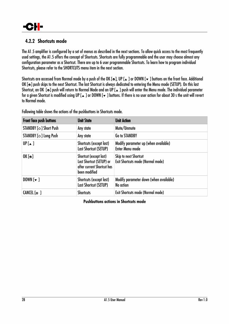
The GAIN Shortcut provides a good illustration of how to navigate a Shortcut screen. Navigating other Shortcuts is similar.
GAIN Shortcut display elements
(1) Shortcut title (parameter being adjusted, for other Shortcuts, title changes accordingly)(2) Arrow indicating UP button [N]. The item below indicates the next parameter value (up direction)(3) Next parameter Value if UP button [N] is pushed (parameter up)(4) Current parameter Value(5) Next parameter Value if DOWN button [O] is pushed (parameter down)(6) Arrow indicating DOWN button [O] if applies. The item below indicates the previous parameter value (down direction)
The last Shortcut (SETUP) is always the same and cannot be removed or altered. It gives access the Menu mode to access the detailed setup of the unit.
Rev 1.0 A1.5 User Manual 29
GAIN
0 dB+0.5 dB
(1)
(3)
(4)
(5)
(2)
-0.5 dBDF(6)
DETAILED SETUP
EXIT
(1)
(4)
(2)
ENTERD (3)
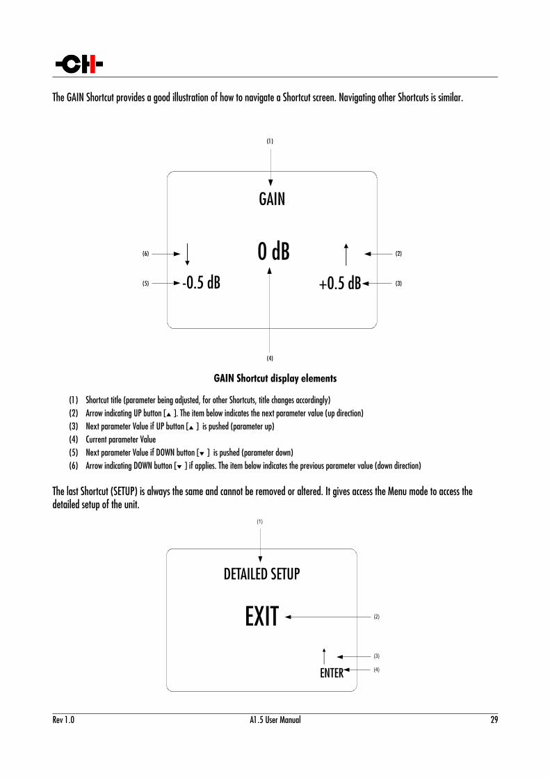
SETUP Shortcut display elements(1) Shortcut title. It indicates that Detailed Setup (Menu mode) can be entered at this stage(2) Current value of the parameter. Default action is to exit (go back to Normal mode)(3) Arrow indicating UP button [N] (4) Next parameter value. If UP button [N] is pushed, the unit enters into Menu mode
4.2.3 Menu mode
The Menu mode allows for Configuration and Setup of the A1.5 power amplifier through a set of menus. Menu mode is entered from the last Shortcut item (see above). From Normal mode, enter the Shortcut mode by pushing the OK [R] button. By successive OK [R] button pushes, step to the last Shortcut item (DETAILED SETUP) and push the TOP [N] button once to enter the Menu mode. If no shortcut is configured, simply press the OK [R] button once to enter the Menu mode.
Navigation in Menu mode is based on UP [N] and DOWN [O] buttons to select an item or to change a value. The OK [R] button is used for validation and CANCEL [Q] to exit without saving.
Front face push buttons Unit Action
STANDBY [S] Short Push Mute/Unmute the unit
STANDBY [S] Long Push Put the unit into Standby
UP [N] Move to next menu item upward
OK [R] Enter next menu level or Validate choice (save setting)
DOWN [O] Move to next menu item downward
CANCEL [Q] Return to previous menu level without saving
Pushbuttons actions in Menu mode
Following illustration shows the elements of a the A1.5 SETUP Menu page, the entry point to the A1.5 menu structure.
30 A1.5 User Manual Rev 1.0
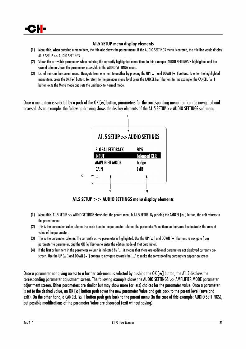
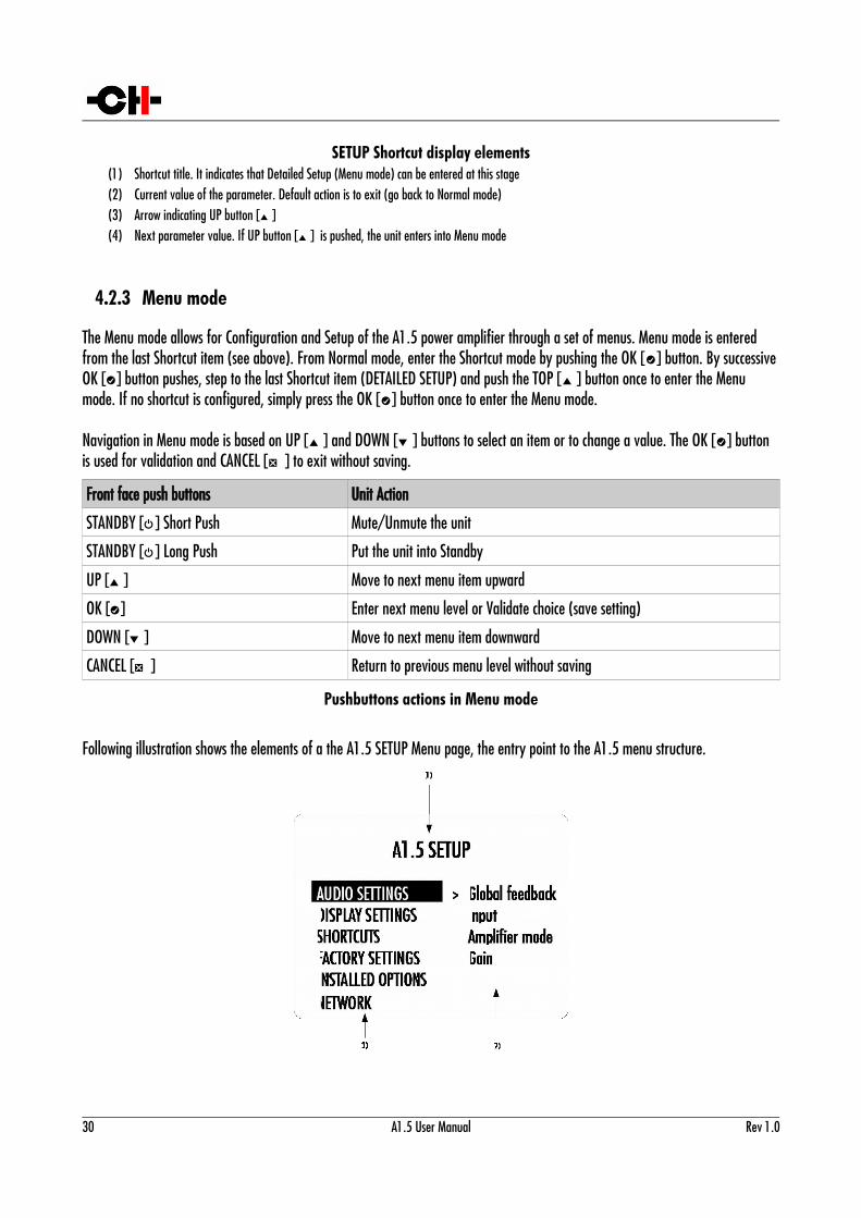
A1.5 SETUP menu display elements(1) Menu title. When entering a menu item, the title also shows the parent menu. If the AUDIO SETTINGS menu is entered, the title line would display
A1.5 SETUP >> AUDIO SETTINGS.(2) Shows the accessible parameters when entering the currently highlighted menu item. In this example, AUDIO SETTINGS is highlighted and the
second column shows the parameters accessible in the AUDIO SETTINGS menu.(3) List of items in the current menu. Navigate from one item to another by pressing the UP [N] and DOWN [O] buttons. To enter the highlighted
menu item, press the OK [R] button. To return to the previous menu level press the CANCEL [Q] button. In this example, the CANCEL [Q] button exits the Menu mode and sets the unit back to Normal mode.
Once a menu item is selected by a push of the OK [R] button, parameters for the corresponding menu item can be navigated and accessed. As an example, the following drawing shows the display elements of the A1.5 SETUP >> AUDIO SETTINGS sub-menu.
A1.5 SETUP >> AUDIO SETTINGS menu display elements
(1) Menu title. A1.5 SETUP >> AUDIO SETTINGS shows that the parent menu is A1.5 SETUP. By pushing the CANCEL [Q] button, the unit returns to the parent menu.
(2) This is the parameter Value column. For each item in the parameter column, the parameter Value item on the same line indicates the current value of the parameter.
(3) This is the parameter column. The currently active parameter is highlighted. Use the UP [N] and DOWN [O] buttons to navigate from parameter to parameter, and the OK [R] button to enter the edition mode of that parameter.
(4) If the first or last item in the parameter column is indicated by '...' it means that there are additional parameters not displayed currently on-screen. Use the UP [N] and DOWN [O] buttons to navigate towards the '...' to make the corresponding parameters appear on screen.
Once a parameter not giving access to a further sub-menu is selected by pushing the OK [R] button, the A1.5 displays the corresponding parameter adjustment screen. The following example shows the AUDIO SETTINGS >> AMPLIFIER MODE parameter adjustment screen. Other parameters are similar but may show more (or less) choices for the parameter value. Once a parameter is set to the desired value, an OK [R] button push saves the new parameter Value and gets back to the parent level (save and exit). On the other hand, a CANCEL [Q] button push gets back to the parent menu (in the case of this example: AUDIO SETTINGS),but possible modifications of the parameter Value are discarded (exit without saving).
Rev 1.0 A1.5 User Manual 31
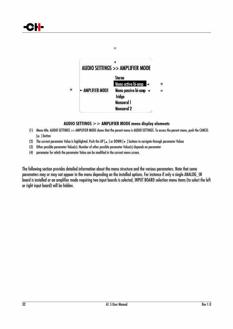
AUDIO SETTINGS >> AMPLIFIER MODE menu display elements(1) Menu title. AUDIO SETTINGS >> AMPLIFIER MODE shows that the parent menu is AUDIO SETTINGS. To access the parent menu, push the CANCEL
[Q] button(2) The current parameter Value is highlighted. Push the UP [N] or DOWN [O] buttons to navigate through parameter Values(3) Other possible parameter Value(s). Number of other possible parameter Value(s) depends on parameter(4) parameter for which the parameter Value can be modified in the current menu screen.
The following section provides detailed information about the menu structure and the various parameters. Note that some parameters may or may not appear in the menu depending on the installed options. For instance if only a single ANALOG_IN board is installed or an amplifier mode requiring two input boards is selected, INPUT BOARD selection menu items (to select the leftor right input board) will be hidden.
32 A1.5 User Manual Rev 1.0
4.3 Configuration
There are five main menus used for configuration of the A1.5:
• AUDIO SETTINGS: Allows to adjust audio related parameters
• DISPLAY SETTINGS: Allows to adjust display related parameters
• SHORTCUTS: Allows to assign and modify Shortcuts for user interface customization
• FACTORY SETTINGS: Indicates the software version and allows to update it. Also allows to return to factory settings
• INSTALLED OPTIONS: Provides information about the installed optional slot-in boards
• NETWORK: Provides information about the network setup and enables its configuration
4.3.1 A1.5 configuration menu items
4.3.1.1 AUDIO SETTINGS
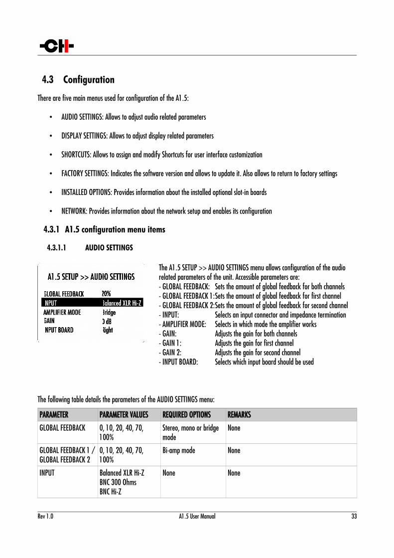
The A1.5 SETUP >> AUDIO SETTINGS menu allows configuration of the audio related parameters of the unit. Accessible parameters are:- GLOBAL FEEDBACK:- GLOBAL FEEDBACK 1:- GLOBAL FEEDBACK 2:- INPUT:- AMPLIFIER MODE:- GAIN:- GAIN 1:- GAIN 2:- INPUT BOARD:
Sets the amount of global feedback for both channelsSets the amount of global feedback for first channelSets the amount of global feedback for second channelSelects an input connector and impedance terminationSelects in which mode the amplifier worksAdjusts the gain for both channelsAdjusts the gain for first channelAdjusts the gain for second channelSelects which input board should be used
The following table details the parameters of the AUDIO SETTINGS menu:
PARAMETER PARAMETER VALUES REQUIRED OPTIONS REMARKS
GLOBAL FEEDBACK 0, 10, 20, 40, 70, 100%
Stereo, mono or bridge mode
None
GLOBAL FEEDBACK 1 /GLOBAL FEEDBACK 2
0, 10, 20, 40, 70, 100%
Bi-amp mode None
INPUT Balanced XLR Hi-ZBNC 300 OhmsBNC Hi-Z
None None
Rev 1.0 A1.5 User Manual 33
RCA 300 OhmsRCA Hi-Z
AMPLIFIER MODE StereoMono active bi-ampMono passive bi-ampBridgeMonaural 1Monaural 2
2 input boards2 input boards, 2 amps2 amps2 amps2 amps2 amps
None
GAIN 24 dB range by 0.5 dB steps
Stereo, mono or bridge mode
None
GAIN 1 / GAIN 2
24 dB range by 0.5 dB steps
Bi-amp mode In passive bi-amp mode, channels 1 and 2 can only have a gain difference of up to 6 dB
INPUT BOARD Left, Right 2 input boards + passivebi-amp, mono or bridge mode
Details of AUDIO SETTINGS menu parameters
4.3.1.2 DISPLAY SETTINGS
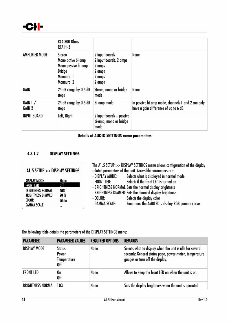
The A1.5 SETUP >> DISPLAY SETTINGS menu allows configuration of the display related parameters of the unit. Accessible parameters are:- DISPLAY MODE:- FRONT LED:- BRIGHTNESS NORMAL:- BRIGHTNESS DIMMED:- COLOR:- GAMMA SCALE:
Selects what is displayed in normal modeSelects if the front LED is turned onSets the normal display brightnessSets the dimmed display brightnessSelects the display colorFine tunes the AMOLED's display RGB gamma curve
The following table details the parameters of the DISPLAY SETTINGS menu:
PARAMETER PARAMETER VALUES REQUIRED OPTIONS REMARKS
DISPLAY MODE StatusPowerTemperatureOff
None Selects what to display when the unit is idle for several seconds: General status page, power-meter, temperature gauges or turn off the display.
FRONT LED OnOff
None Allows to keep the front LED on when the unit is on.
BRIGHTNESS NORMAL 10% None Sets the display brightness when the unit is operated.
34 A1.5 User Manual Rev 1.0
20%30%...90%100%
BRIGHTNESS DIMMED 10%20%30%
None Sets the display brightness when the unit is left idle for several seconds.
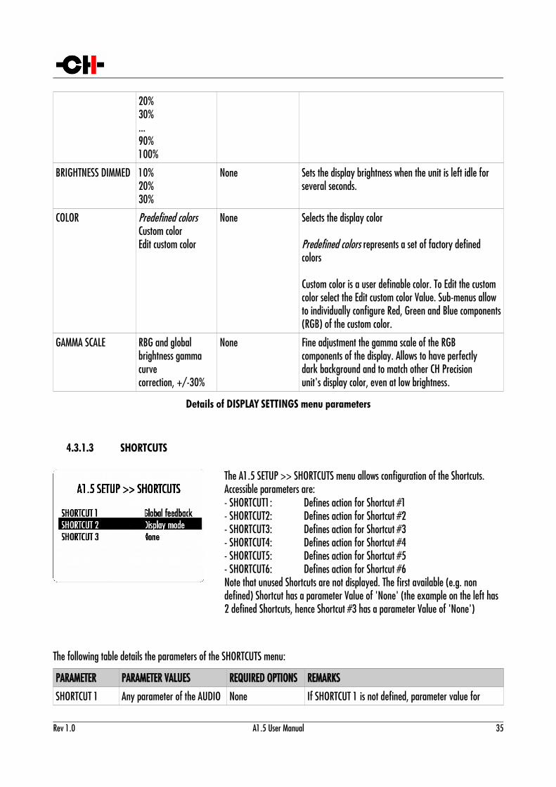
COLOR Predefined colorsCustom colorEdit custom color
None Selects the display color
Predefined colors represents a set of factory defined colors
Custom color is a user definable color. To Edit the custom color select the Edit custom color Value. Sub-menus allow to individually configure Red, Green and Blue components(RGB) of the custom color.
GAMMA SCALE RBG and globalbrightness gamma curvecorrection, +/-30%
None Fine adjustment the gamma scale of the RGBcomponents of the display. Allows to have perfectlydark background and to match other CH Precisionunit's display color, even at low brightness.
Details of DISPLAY SETTINGS menu parameters
4.3.1.3 SHORTCUTS
The A1.5 SETUP >> SHORTCUTS menu allows configuration of the Shortcuts. Accessible parameters are:- SHORTCUT1:- SHORTCUT2:- SHORTCUT3:- SHORTCUT4:- SHORTCUT5:- SHORTCUT6:
Defines action for Shortcut #1Defines action for Shortcut #2Defines action for Shortcut #3Defines action for Shortcut #4Defines action for Shortcut #5Defines action for Shortcut #6
Note that unused Shortcuts are not displayed. The first available (e.g. non defined) Shortcut has a parameter Value of 'None' (the example on the left has 2 defined Shortcuts, hence Shortcut #3 has a parameter Value of 'None')
The following table details the parameters of the SHORTCUTS menu:
PARAMETER PARAMETER VALUES REQUIRED OPTIONS REMARKS
SHORTCUT 1 Any parameter of the AUDIO None If SHORTCUT 1 is not defined, parameter value for
Rev 1.0 A1.5 User Manual 35
SETTINGS and DISPLAY SETTINGS menus or None
SHORTCUT 1 is set to 'None'. SHORTCUT 2 to 6 are not displayed in this case.
SHORTCUT 2 Any parameter of the AUDIO SETTINGS and DISPLAY SETTINGS menus or None
None If SHORTCUT 2 is not defined, parameter value for SHORTCUT 2 is set to 'None'. SHORTCUT 3 to 6 are not displayed in this case.
SHORTCUT 3 Any parameter of the AUDIO SETTINGS and DISPLAY SETTINGS menus or None
None If SHORTCUT 3 is not defined, parameter value for SHORTCUT 3 is set to 'None'. SHORTCUT 4 to 6 are not displayed in this case.
SHORTCUT 4 Any parameter of the AUDIO SETTINGS and DISPLAY SETTINGS menus or None
None If SHORTCUT 4 is not defined, parameter value for SHORTCUT 4 is set to 'None'. SHORTCUT 5 and 6 are notdisplayed in this case.
SHORTCUT 5 Any parameter of the AUDIO SETTINGS and DISPLAY SETTINGS menus or None
None If SHORTCUT 5 is not defined, parameter value for SHORTCUT 5 is set to 'None'. SHORTCUT 6 is not displayed in this case.
SHORTCUT 6 Any parameter of the AUDIO SETTINGS and DISPLAY SETTINGS menus or None
None If SHORTCUT 6 is not defined, parameter value for SHORTCUT 6 is set to 'None'.
Details of SHORTCUTS menu parameters
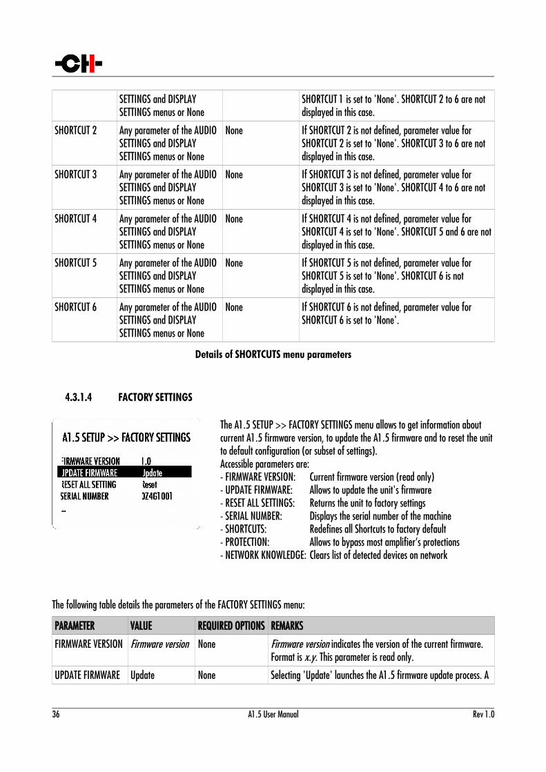
4.3.1.4 FACTORY SETTINGS
The A1.5 SETUP >> FACTORY SETTINGS menu allows to get information about current A1.5 firmware version, to update the A1.5 firmware and to reset the unitto default configuration (or subset of settings).Accessible parameters are:- FIRMWARE VERSION:- UPDATE FIRMWARE:- RESET ALL SETTINGS:- SERIAL NUMBER:- SHORTCUTS:- PROTECTION:- NETWORK KNOWLEDGE:
Current firmware version (read only)Allows to update the unit's firmwareReturns the unit to factory settingsDisplays the serial number of the machineRedefines all Shortcuts to factory defaultAllows to bypass most amplifier’s protectionsClears list of detected devices on network
The following table details the parameters of the FACTORY SETTINGS menu:
PARAMETER VALUE REQUIRED OPTIONS REMARKS
FIRMWARE VERSION Firmware version None Firmware version indicates the version of the current firmware. Format is x.y. This parameter is read only.
UPDATE FIRMWARE Update None Selecting 'Update' launches the A1.5 firmware update process. A
36 A1.5 User Manual Rev 1.0
USB flash drive with a valid set of firmware must be inserted in the back panel USB port
RESET ALL SETTINGS Reset None Selecting 'Reset' returns the A1.5 to its factory settings.
SERIAL NUMBER Serial number None Serial number indicates the serial number of the A1.5. Format is xxxx10nn. This parameter is read only.
SHORTCUTS Default shortcuts None Selecting 'Default Mapping' returns the A1.5's Shortcuts to their factory settings. Factory settings are detailed in the Specificationssection.
PROTECTION DisabledEnabled
None Output short-circuit, output-DC, over-heat and amplifier-fault detection circuitry protect both the amplifier and the connected loudspeakers. In some regions of the world, the power distribution grid can be so polluted that spurious power grid noisecan trig false error, thus muting or powering down the amplifier. In such extreme cases, and if it is of major importance that the A1.5 runs uninterrupted, protections can be temporary disabled by the end user, at his own risk.
NETWORK KNOWLEDGE
Reset None Clears the A1.5's memory of other CH Precision devices it has discovered through the TCP/UDP proprietary protocol.
Details of FACTORY SETTINGS menu parameters
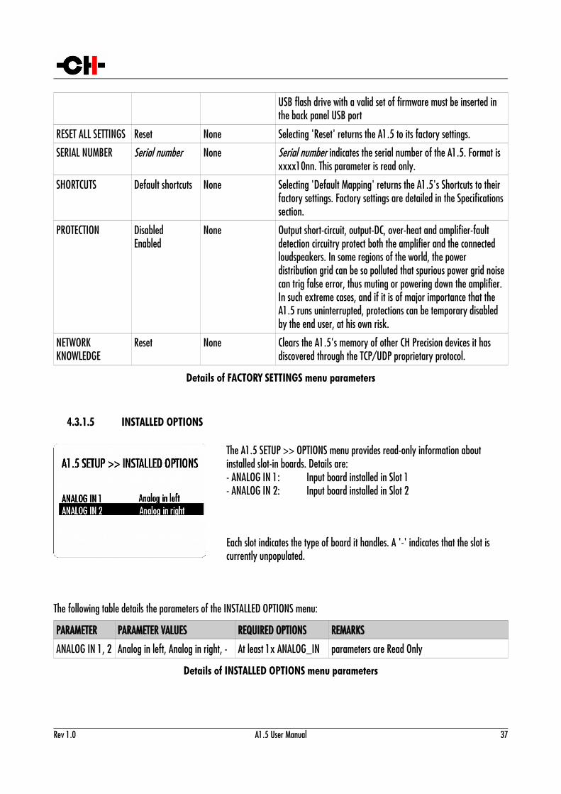
4.3.1.5 INSTALLED OPTIONS
The A1.5 SETUP >> OPTIONS menu provides read-only information about installed slot-in boards. Details are:- ANALOG IN 1:- ANALOG IN 2:
Input board installed in Slot 1Input board installed in Slot 2
Each slot indicates the type of board it handles. A '-' indicates that the slot is currently unpopulated.
The following table details the parameters of the INSTALLED OPTIONS menu:
PARAMETER PARAMETER VALUES REQUIRED OPTIONS REMARKS
ANALOG IN 1, 2 Analog in left, Analog in right, - At least 1x ANALOG_IN parameters are Read Only
Details of INSTALLED OPTIONS menu parameters
Rev 1.0 A1.5 User Manual 37
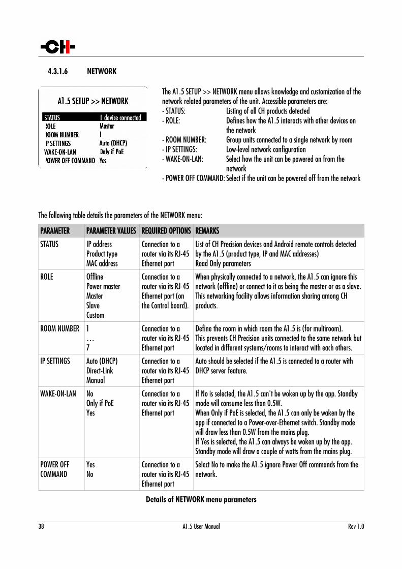
4.3.1.6 NETWORK
The A1.5 SETUP >> NETWORK menu allows knowledge and customization of the network related parameters of the unit. Accessible parameters are:- STATUS:- ROLE:
- ROOM NUMBER:- IP SETTINGS:- WAKE-ON-LAN:
- POWER OFF COMMAND:
Listing of all CH products detectedDefines how the A1.5 interacts with other devices on the networkGroup units connected to a single network by roomLow-level network configurationSelect how the unit can be powered on from the networkSelect if the unit can be powered off from the network
The following table details the parameters of the NETWORK menu:
PARAMETER PARAMETER VALUES REQUIRED OPTIONS REMARKS
STATUS IP addressProduct typeMAC address
Connection to a router via its RJ-45 Ethernet port
List of CH Precision devices and Android remote controls detected by the A1.5 (product type, IP and MAC addresses)Read Only parameters
ROLE OfflinePower masterMasterSlaveCustom
Connection to a router via its RJ-45 Ethernet port (on the Control board).
When physically connected to a network, the A1.5 can ignore this network (offline) or connect to it as being the master or as a slave.This networking facility allows information sharing among CH products.
ROOM NUMBER 1…7
Connection to a router via its RJ-45 Ethernet port
Define the room in which room the A1.5 is (for multiroom).This prevents CH Precision units connected to the same network butlocated in different systems/rooms to interact with each others.
IP SETTINGS Auto (DHCP)Direct-LinkManual
Connection to a router via its RJ-45 Ethernet port
Auto should be selected if the A1.5 is connected to a router with DHCP server feature.
WAKE-ON-LAN NoOnly if PoEYes
Connection to a router via its RJ-45 Ethernet port
If No is selected, the A1.5 can't be woken up by the app. Standby mode will consume less than 0.5W.When Only if PoE is selected, the A1.5 can only be waken by the app if connected to a Power-over-Ethernet switch. Standby mode will draw less than 0.5W from the mains plug.If Yes is selected, the A1.5 can always be woken up by the app. Standby mode will draw a couple of watts from the mains plug.
POWER OFF COMMAND
YesNo
Connection to a router via its RJ-45 Ethernet port
Select No to make the A1.5 ignore Power Off commands from the network.
Details of NETWORK menu parameters
38 A1.5 User Manual Rev 1.0
5 Firmware update
5.1 Preparing the USB flash-drive
The firmware of all the CH Precision units can be updated using the USB port located at the back of the unit. Before starting the firmware update, it is necessary to load a USB flash-drive (provided in the accessory box) with files containing the new firmware. We recommend to use the CH USB key. If however you have to use another one, please use a FAT32-formatted USB 2.0 flash-driveprovided with your A1.5. The following procedure describes how to load the USB flash-drive with the correct files:
1. Download the latest A1.5 firmware file from www.ch-precision.com
2. Decompress the A15_xxx.zip file and copy the decompressed files to the root of your USB flash-drive. After doing
so, your USB flash-drive should contain the following files:
A1_xxx.5d1
A1_xxx.5m1
A1_xxx.5o1
where 'xxx' indicates the firmware revision.
Make sure all these files are present at the root of your USB flash-drive, and that only one revision of these files is present. Any missing file will make the firmware update procedure fail, while multiple versions of the same unit's firmware can lead to unstableA1.5 behavior after update.
5.2 Updating the unit's firmware
1. Perform the operations described in section 5.1
2. Insert the USB flash-drive into the USB port located at the back of your A1.5 unit
3. Navigate to the FACTORY SETTINGS menu (see section 4) and select the UPDATE FIRMWARE item
4. Start the Firmware Update process by pushing the OK button. Please note that the unit will perform a Reset (the display briefly turns off and on) during the procedure
5. Once the firmware update is complete, the unit automatically goes into Standby mode. Remove the USB flash-drive and turn the unit on. The new firmware is now active. To verify that the firmware update was effective, navigate to the FACTORY SETTINGS menu and select the FIRMWARE VERSION item. The displayed firmware revision should match the firmware revision on the files copied to the USB flash-drive.
Note: The firmware update process lasts 5-10 minutes, do NOT interrupt it!
Rev 1.0 A1.5 User Manual 39
When performing a firmware update, do NOT press any of the unit's front panel buttons, do NOT unplug the unit from the AC wall socket and do NOT turn the mains power switch off. Interruption of the firmware update procedure may result in corrupted firmware and a malfunctioning unit. If something went wrong during a firmware update and the unit is malfunctioning, apply the emergency firmware update procedure described in the next section.
5.3 Emergency firmware update procedure
Perform the following Emergency Firmware Update procedure if your unit doesn’t power up normally.
1. Perform the operations described in section 5.1
2. Power the unit off (back panel mains power switch to OFF)
3. Push and keep the standby/mute button pushed while powering up the unit (back panel mains power switch to ON). Keep the standby/mute button pushed for a couple more seconds after you turned the unit on.
4. The unit performs the emergency firmware update. Once the operation is complete, the unit automatically goes into Standby mode. Remove the USB flash-drive and turn the unit on. The new firmware is now active. To verify that the firmware update was effective, navigate to the FACTORY SETTINGS menu and select the FIRMWARE VERSION item. Thedisplayed firmware revision should match the firmware revision on the files copied to the USB flash-drive.
Note: The emergency firmware update procedure lasts 5-10 minutes, do NOT interrupt it!
40 A1.5 User Manual Rev 1.0
6 Troubleshooting
Error Action
No power Check the AC power cordCheck the power button at the back of the unitCheck both fuses at the back of the unit
No sound(general)
Check that your source is playingCheck that your A1.5 is turned on and that loudspeakers are properly connected according to the desired amplification modeCheck that the system volume setting is not too lowCheck that the correct input is selected on your preamplifierCheck that the correct input is selected on your A1.5 amplifierCheck that the correct amplifier mode is engaged
No sound(“7” is displayed)
Your A1.5 is muted (display area 2 7 must be off). Unmute using the top button
Lost in the settings? Restore factory settings and start your setup again
Software update fails Try the Emergency Software Update procedureIf it fails, download the latest A1.5 firmware from www.ch-precision.com, prepare a software update image on the provided FAT32 formatted USB flash drive and run the Emergency Software Update procedure again
USB flash drive for firmwareupdate is not detected by A1.5
Please try another brand of USB flash drive (e.g. Sandisk).
Troubleshooting
If the error cannot be corrected using the information from the above table, disconnect the unit from AC wall power and from the rest of your system and contact your authorized dealer.
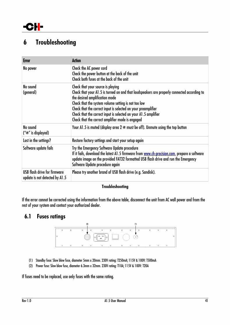
6.1 Fuses ratings
(1) Standby fuse: Slow blow fuse, diameter 5mm x 20mm. 230V rating: T250mA; 115V & 100V: T500mA(2) Power fuse: Slow blow fuse, diameter 6.3mm x 32mm. 230V rating: T10A; 115V & 100V: T20A
If fuses need to be replaced, use only fuses with the same rating.
Rev 1.0 A1.5 User Manual 41
7 Specifications
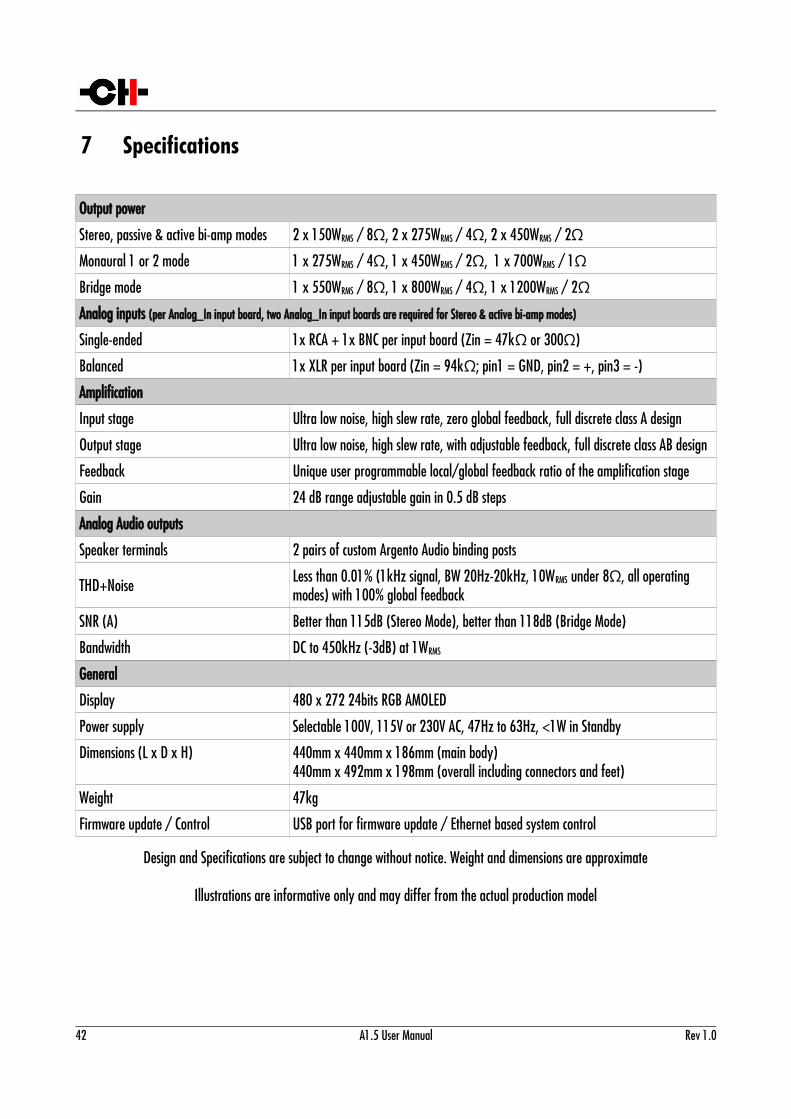
Output power
Stereo, passive & active bi-amp modes 2 x 150WRMS / 8Ω, 2 x 275WRMS / 4Ω, 2 x 450WRMS / 2ΩMonaural 1 or 2 mode 1 x 275WRMS / 4Ω, 1 x 450WRMS / 2 , 1 x 700WΩ RMS / 1ΩBridge mode 1 x 550WRMS / 8Ω, 1 x 800WRMS / 4Ω, 1 x 1200WRMS / 2ΩAnalog inputs (per Analog_In input board, two Analog_In input boards are required for Stereo & active bi-amp modes)
Single-ended 1x RCA + 1x BNC per input board (Zin = 47kΩ or 300Ω)
Balanced 1x XLR per input board (Zin = 94kΩ; pin1 = GND, pin2 = +, pin3 = -)
Amplification
Input stage Ultra low noise, high slew rate, zero global feedback, full discrete class A design
Output stage Ultra low noise, high slew rate, with adjustable feedback, full discrete class AB design
Feedback Unique user programmable local/global feedback ratio of the amplification stage
Gain 24 dB range adjustable gain in 0.5 dB steps
Analog Audio outputs
Speaker terminals 2 pairs of custom Argento Audio binding posts
THD+Noise Less than 0.01% (1kHz signal, BW 20Hz-20kHz, 10WRMS under 8Ω, all operating modes) with 100% global feedback
SNR (A) Better than 115dB (Stereo Mode), better than 118dB (Bridge Mode)
Bandwidth DC to 450kHz (-3dB) at 1WRMS
General
Display 480 x 272 24bits RGB AMOLED
Power supply Selectable 100V, 115V or 230V AC, 47Hz to 63Hz, <1W in Standby
Dimensions (L x D x H) 440mm x 440mm x 186mm (main body)440mm x 492mm x 198mm (overall including connectors and feet)
Weight 47kg
Firmware update / Control USB port for firmware update / Ethernet based system control
Design and Specifications are subject to change without notice. Weight and dimensions are approximate
Illustrations are informative only and may differ from the actual production model
42 A1.5 User Manual Rev 1.0
FCC-Notice
Note: This equipment has been tested and found to comply with the limits for a Class B digital device, pursuant to Part 15 of the FCC Rules. These limits are designed to provide reasonable protection against harmful interference in a residential installation. This equipment generates, uses and can radiate radio frequency energy and, if not installed and used in accordance with the instructions, may cause harmful interference to radio communications. However there is no guarantee that interference will not occur in a particular installation.
If this equipment does cause harmful interference to radio or television reception, which can be determined by turning the equipment off and on, the user is encouraged to try to correct the interference by one or more of the following measures:
adjust or relocate the receiving antenna
increase the separation between the equipment and the receiver
connect the equipment into a mains outlet on a circuit different from that to which the receiver is connected
consult the dealer or an experienced ratio/TV technician for help
Disposal – Environmental care
Directive 2002/96/EG of the European Parliament requires consumer electro-technical appliances to bedisposed separately and have to be indicated with the following symbol. Should you dispose thiscomponent please do so in conformity with local and global legal and environmental regulations andaccording to best practices. We strongly encourage you to recycle any batteries used with this component.
Rev 1.0 A1.5 User Manual 43