Embed Size (px)
Citation preview
International Research Journal of Engineering and Technology (IRJET) e-ISSN: 2395 -0056
Volume: 03 Issue: 05 | May-2016 www.irjet.net p-ISSN: 2395-0072
© 2016, IRJET | Impact Factor value: 4.45 | ISO 9001:2008 Certified Journal | Page 1305
A wideband profile corrugated horn for parabolic reflector antenna
Nirav N. Rajan1, Asst. Prof. Anuj M. Patel2
1Student, Communication system engineering (EC), Saraswati College of Engineering, Kadi, Gujarat, India
2 Assistant Professor, Communication system engineering (EC), Saraswati College of Engineering, Kadi, Gujarat, India
---------------------------------------------------------------------***---------------------------------------------------------------------
Abstract – As demand increase in wireless applications it must be necessary to improvement in the antenna abilities as wideband capabilities. For wideband capability antenna should have low cross polarization, low side lobe level and beam symmetry. For achieving this much of characteristics a wideband profile corrugated horn antenna is designed which can able to improve the performance of the parabolic reflector. Designing of this antenna is carried out in software named HFSS (High Frequency Structure Simulator) which is one of the tools for designing antenna accurately and effectively. A theoretical parameter is related to the mode conversion section in which TE11 mode is converted to HE11 mode by cylindrical corrugated horn with varying slot depth.[1] Here the horn is made for X band which is used for the satellite communication. Mode conversion is carried out by the different profiles like linear profile mode-matching technique and Variable-depth mode converter technique that makes it suitable for wide range of frequency band. This type of the corrugated horn is more suitable as a feed for the parabolic reflector antenna.
Key Words: Wideband Profiled corrugated horn; mode conversion; TE11 –
to - HE11, Linear variable slot profile, Variable depth slot
mode profile.
1. INTRODUCTION
Antennas are metallic transducers which convert electrical signals into the electromagnetic signals. There are different antennas are available for the different applications. Some of the listed as Dipole antenna, Loop antenna, Log periodic antenna, Yagi-Uda antenna, horn antenna, Parabolic reflector antenna etc. Among of them lots of the antennas are used for the satellite communications. Specially Horn antenna and reflector antenna are very efficiently suitable for satellite communication because of them highly directional efficiency. One of the simplest and probably the most widely used microwave antenna is the Horn. A horn antenna is an antenna that consist of a flaring metal waveguide shaped like horn to radio waves in beam. Specially the horn with corrugation which makes its inner surface discontinues and this discontinuity will help to convert the single mode into
hybrid mode like TE11 to HE11. This mode conversion due to corrugation has advantages like moderate directivity, low standing wave ratio (SWR), broad bandwidth, simple construction and adjustment. An advantage of horn antennas is that since they have no resonant elements, they can operate over a wide range of frequencies, a wide bandwidth.
2. LITERATURE SURVEY
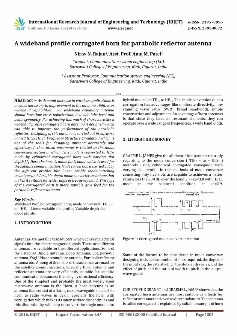
GRAEME L. JAMES give the all theoretical parametric study regarding to the mode conversion ( TE11 – to – HE11 ) methods using cylindrical corrugated waveguide with varying slot depth. In this methods of mode converter consisting only five slots are capable to achieves a better return loss then 30 dB over the band 2.7<ka<3.8 with HE11 mode in the balanced condition at ka=2.9.
Figure 1: Corrugated mode converter section.
Some of the factors to be considered in mode converter designing include the number of slots required, the depth of the input slot, the rate at which the slot depth varies, and the effect of pitch and the ratio of width to pitch in the output wave-guide.
CHRISTOPHE GRANET and GRAEME L. JAMES shows that the corrugated horn antennas are most suitable as a feeds for reflector antennas and even as direct radiators. That antenna is called corrugated is explained by suitable example of horn
International Research Journal of Engineering and Technology (IRJET) e-ISSN: 2395 -0056
Volume: 03 Issue: 05 | May-2016 www.irjet.net p-ISSN: 2395-0072
© 2016, IRJET | Impact Factor value: 4.45 | ISO 9001:2008 Certified Journal | Page 1306
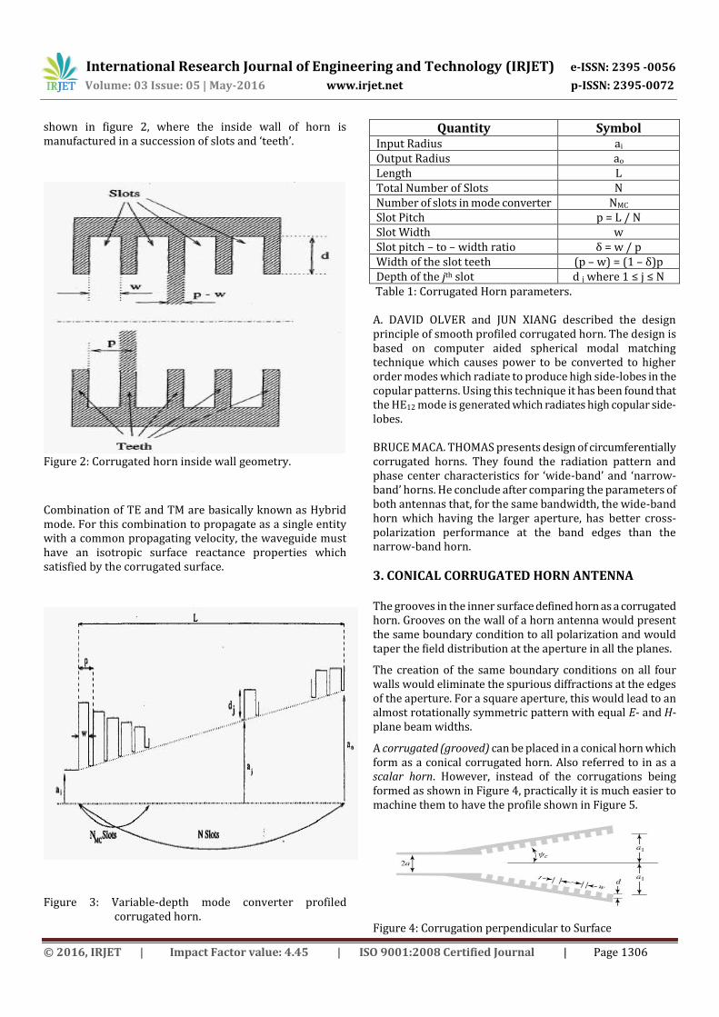
shown in figure 2, where the inside wall of horn is manufactured in a succession of slots and ‘teeth’.
Figure 2: Corrugated horn inside wall geometry.
Combination of TE and TM are basically known as Hybrid mode. For this combination to propagate as a single entity with a common propagating velocity, the waveguide must have an isotropic surface reactance properties which satisfied by the corrugated surface.
Figure 3: Variable-depth mode converter profiled corrugated horn.
Quantity Symbol Input Radius ai Output Radius ao Length L Total Number of Slots N Number of slots in mode converter NMC Slot Pitch p = L / N Slot Width w Slot pitch – to – width ratio δ = w / p Width of the slot teeth (p – w) = (1 – δ)p Depth of the jth slot d j where 1 ≤ j ≤ N
Table 1: Corrugated Horn parameters. A. DAVID OLVER and JUN XIANG described the design principle of smooth profiled corrugated horn. The design is based on computer aided spherical modal matching technique which causes power to be converted to higher order modes which radiate to produce high side-lobes in the copular patterns. Using this technique it has been found that the HE12 mode is generated which radiates high copular side-lobes. BRUCE MACA. THOMAS presents design of circumferentially corrugated horns. They found the radiation pattern and phase center characteristics for ‘wide-band’ and ‘narrow-band’ horns. He conclude after comparing the parameters of both antennas that, for the same bandwidth, the wide-band horn which having the larger aperture, has better cross-polarization performance at the band edges than the narrow-band horn.
3. CONICAL CORRUGATED HORN ANTENNA The grooves in the inner surface defined horn as a corrugated horn. Grooves on the wall of a horn antenna would present the same boundary condition to all polarization and would taper the field distribution at the aperture in all the planes.
The creation of the same boundary conditions on all four walls would eliminate the spurious diffractions at the edges of the aperture. For a square aperture, this would lead to an almost rotationally symmetric pattern with equal E- and H-plane beam widths.
A corrugated (grooved) can be placed in a conical horn which form as a conical corrugated horn. Also referred to in as a scalar horn. However, instead of the corrugations being formed as shown in Figure 4, practically it is much easier to machine them to have the profile shown in Figure 5.
Figure 4: Corrugation perpendicular to Surface
International Research Journal of Engineering and Technology (IRJET) e-ISSN: 2395 -0056
Volume: 03 Issue: 05 | May-2016 www.irjet.net p-ISSN: 2395-0072
© 2016, IRJET | Impact Factor value: 4.45 | ISO 9001:2008 Certified Journal | Page 1307
Figure 5: Corrugation perpendicular to Axis
To form an effective corrugated surface, it usually requires 10 or more slots (corrugations) per wavelength. To simplify the analysis of an infinite corrugated surface, the following assumptions are usually required:
1. The teeth of the corrugations are vanishingly thin.
2. Reflections from the base of the slot are only those of a TEM mode.
4. DESIGN PARAMETERS
1. This is designed for X-band (8 - 12 GHz). 2. Operating frequency 10 GHz. 3. The input radius contain TE11 mode. 4. The length of input waveguide. 5. Total length and Flare angle. 6. Nominal Slot-Depth calculation. 7. Pitch and Pitch – Width Ratio. 8. Choice of the Formulation of Profile. 9. The output radius contains TE11+ HE11 mode. 10. The length L of the output waveguide.
4.1 Prototype of corrugated horn with Linear
Profile Mode Matching Technique:
Figure 6: Prototype of linear mode matching technique
profile
4.1.1 Mode Matching Technique parameters:
Parameters Equations
Wavelength λ0 =
Pitch P = (0.1) λ0
Slot Width W(b i) = (0.75) P
Width of the Slot teeth
T(d i) = P – W
Initial Radius a i =
Table – 1: Mode Matching Technique parameters
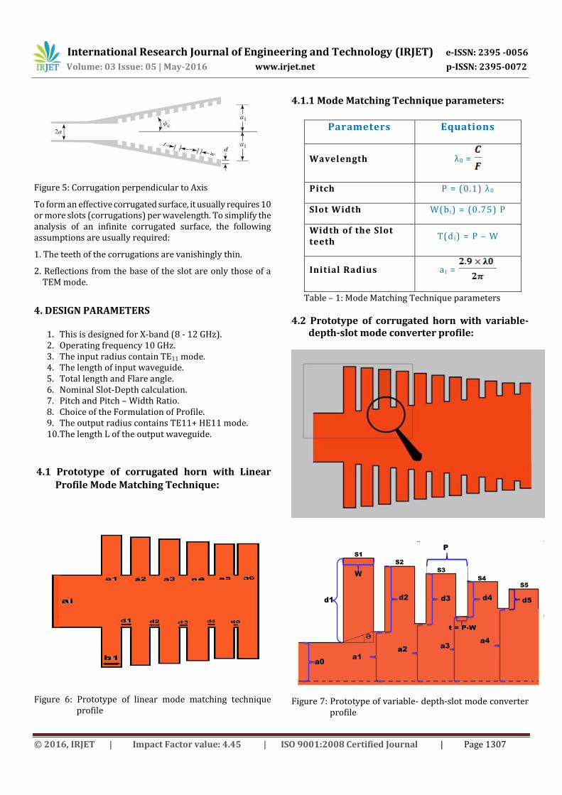
4.2 Prototype of corrugated horn with variable- depth-slot mode converter profile:
Figure 7: Prototype of variable- depth-slot mode converter profile
International Research Journal of Engineering and Technology (IRJET) e-ISSN: 2395 -0056
Volume: 03 Issue: 05 | May-2016 www.irjet.net p-ISSN: 2395-0072
© 2016, IRJET | Impact Factor value: 4.45 | ISO 9001:2008 Certified Journal | Page 1308
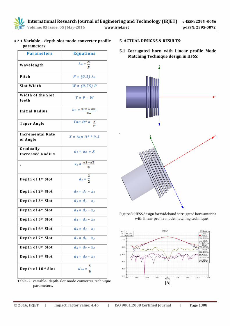
4.2.1 Variable - depth-slot mode converter profile parameters:
Parameters Equations
Wavelength λ0 =
Pitch P = (0.1) λ0
Slot Width W = (0.75) P
Width of the Slot
teeth T = P – W
Initial Radius a0 =
Taper Angle Tan ϴº =
Incremental Rate
of Angle X = tan ϴº * 0.3
Gradually
Increased Radius a1 = a0 + X
- x3 =
Depth of 1s t Slot d1 =
Depth of 2s t Slot d2 = d1 – x3
Depth of 3s t Slot d3 = d2 – x3
Depth of 4s t Slot d4 = d3 – x3
Depth of 5s t Slot d5 = d4 – x3
Depth of 6s t Slot d6 = d5 – x3
Depth of 7s t Slot d7 = d6 – x3
Depth of 8s t Slot d8 = d7 – x3
Depth of 9s t Slot d9 = d8 – x3
Depth of 10s t Slot d1 0 =
Table–2: variable- depth-slot mode converter technique parameters.
5. ACTUAL DESIGNS & RESULTS: 5.1 Corrugated horn with Linear profile Mode
Matching Technique design in HFSS:
Figure 8: HFSS design for wideband corrugated horn antenna
with linear profile mode matching technique.
[A]
International Research Journal of Engineering and Technology (IRJET) e-ISSN: 2395 -0056
Volume: 03 Issue: 05 | May-2016 www.irjet.net p-ISSN: 2395-0072
© 2016, IRJET | Impact Factor value: 4.45 | ISO 9001:2008 Certified Journal | Page 1309
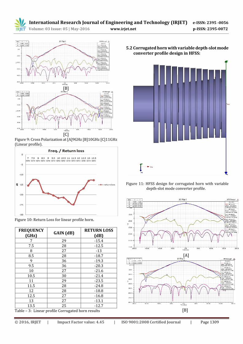
[B]
[C]
Figure 9: Cross Polarization at [A]9GHz [B]10GHz [C]11GHz (Linear profile).
Figure 10: Return Loss for linear profile horn.
FREQUENCY (GHz)
GAIN (dB) RETURN LOSS
(dB) 7 29 -15.4
7.5 28 -12.5 8 27 -13
8.5 28 -18.7 9 36 -19.3
9.5 36 -20.3 10 27 -21.6
10.5 30 -21.4 11 29 -23.5
11.5 28 -24.8 12 28 -18.8
12.5 27 -16.8 13 27 -13.1
13.5 25 -12.7 Table – 3: Linear profile Corrugated horn results
5.2 Corrugated horn with variable depth-slot mode converter profile design in HFSS:
Figure 11: HFSS design for corrugated horn with variable depth-slot mode converter profile.
[A]
[B]
International Research Journal of Engineering and Technology (IRJET) e-ISSN: 2395 -0056
Volume: 03 Issue: 05 | May-2016 www.irjet.net p-ISSN: 2395-0072
© 2016, IRJET | Impact Factor value: 4.45 | ISO 9001:2008 Certified Journal | Page 1310
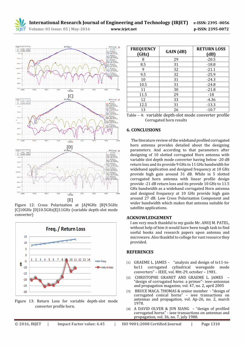
[C]
[D]
[E]
Figure 12: Cross Polarization at [A]9GHz [B]9.5GHz [C]10GHz [D]10.5GHz[E]11GHz (variable depth-slot mode converter)
Figure 13: Return Loss for variable depth-slot mode
converter profile horn.
FREQUENCY
(GHz) GAIN (dB)
RETURN LOSS (dB)
8 29 -20.5 8.5 31 -18.8 9 32 -21.1
9.5 32 -25.9 10 31 -24.3
10.5 31 -24.8 11 30 -21.8
11.5 29 -18 12 33 -4.36
12.5 31 -13.3 13 26 -10.7
Table – 4: variable depth-slot mode converter profile Corrugated horn results
6. CONCLUSIONS
The literature review of the wideband profiled corrugated horn antenna provides detailed about the designing parameters. And according to that parameters after designing of 10 slotted corrugated Horn antenna with variable slot depth mode converter having below -20 dB return loss and its provide 9 GHz to 11 GHz bandwidth for wideband application and designed frequency at 10 GHz provide high gain around 31 dB. While in 5 slotted corrugated horn antenna with linear profile design provide -21 dB return loss and its provide 10 GHz to 11.5 GHz bandwidth as a wideband corrugated Horn antenna and designed frequency at 10 GHz provide high gain around 27 dB. Low Cross Polarization Component and wider bandwidth which makes that antenna suitable for satellite applications.
ACKNOWLEDGEMENT I am very much thankful to my guide Mr. ANUJ M. PATEL, without help of him it would have been tough task to find useful books and research papers upon antenna and microwave. Also thankful to college for vast resource they provided.
REFERENCES [1] GRAEME L. JAMES – “analysis and design of te11-to-
he11 corrugated cylindrical waveguide mode converters” – IEEE, vol. Mtt-29, october – 1981.
[2] CHRISTOPHE GRANET AND GRAEME L. JAMES – “design of corrugated horns: a primer”- ieee-antennas and propagation magazine, vol. 47, no. 2, april 2005
[3] BRUCE MACA. THOMAS & senior member - “design of corrugated conical horns” – ieee transactions on antennas and propagation, vol. Ap-26, no. 2, march 1978.
[4] A DAVID OLVER & JUN XIANG – “design of profiled corrugated horns” - ieee transactions on antennas and propagation, vol. 36, no. 7, july 1988.

International Research Journal of Engineering and Technology (IRJET) e-ISSN: 2395 -0056
Volume: 03 Issue: 05 | May-2016 www.irjet.net p-ISSN: 2395-0072
© 2016, IRJET | Impact Factor value: 4.45 | ISO 9001:2008 Certified Journal | Page 1311
[5] S. SRAVAN KUMAR, M. B. MAHAJAN, RAJEEV JYOTI, V. R. SETH, H. S. SOLADID, AND S. B. SHARMA – “design &development of wide band corrugated horn” - proceedings of international conference on microwave – 08, ieee – 2008.
[6] RAEME J A M E S - “design of wide-band compact corrugated horns” – ieee transactions on antennas and propagation, vol. Ap-34, no. 6, june 1986.
[7] Erik Lier, “
cross polarization from dual mode horn antennas”, ieee transactions on antenna and propagation, jan 1986.
[8] LINGZHEN ZENG, CHARLES L. BENETTE, DAVID T. CHUSS, AND EDWARD J. WOLLACK,“a low cross polarization smooth walled horn with improved bandwidth”.
[9] C. A. BALANIS, antenna theory: analysis and design, 2nd ed. (new york: john wiley & sons, 1996).
[10] S. SILVER, microwave antenna theory and design, mcgraw-hill book company, inc., new york, 1949.
[11] P. D. POTTER, “a new horn antenna with suppressed side lobes and equal beam widths, ”microwave journal, p. 71-78;june, 1963
[12] ELLIOTT R. NAGELBERG ,“design of dual mode conical horn for communication antennas “, bell telephone laboratories, pg. 284-288, 1979.
[13] LINGZHEN ZENG, CHARLES L. BENETTE, DAVID T. CHUSS, and EDWARD J. WOLLACK,“a low cross polarization smooth walled horn with improved bandwidth”.
[14] D. M. POZAR, microwave engineering, 3rd ed, john wiley and sons, inc., london,2004.
[15] JOHN VOLAKIS, antenna engineering handbook, 4th Ed, Mcgraw-Hill Education, 2007.
BIOGRAPHIES
NIRAV N. RAJAN M.E. – Communication System Engineering Ahmedabad, Gujarat, India.
ANUJ M. PATEL Assistant Professor, Communication System Engineering (EC) Saraswati college of engineering & Technology, kadi, Gujarat, India.