Embed Size (px)
Citation preview
Progress In Electromagnetics Research C, Vol. 16, 127–136, 2010
A WIDEBAND MICROSTRIP-LINE-FED ISOSCELESTRAPEZOIDAL DIELECTRIC RESONATOR ANTENNAWITH MODIFIED GROUND PLANE
C. Gopakumar and K. T. Mathew
Department of ElectronicsMicrowave Tomography and Materials Research LaboratoryCochin University of Science and TechnologyKochi-682 022, Kerala State, India
Abstract—A microstrip-line-fed Isosceles Trapezoidal DielectricResonator Antenna (ITDRA) with a parasitic strip and modifiedground plane is introduced. It is proved by simulation andexperiment that the antenna’s resonant frequency can be loweredand the bandwidth can be increased considerably by introducinga slot and optimizing its position and dimensions in the groundplane. The proposed antenna is a wide band antenna with a 2 : 1VSWR bandwidth of 21.5% centered at 2.51 GHz and exhibits goodradiation characteristics and moderate gain in the entire operatingband. The antenna covers important application bands viz. ISM:Bluetooth/WLAN 2.4/Wibree (802.11 b/g/n)/ZigBee, WiBro andDMB. The wideband response in the relatively lower frequencyrange which includes the above mentioned application bands are notmuch seen anywhere in literature. Details of the design along withexperimental and simulation results are presented and discussed.
1. INTRODUCTION
Recently interest has increased in the study of dielectric resonatorantennas for their inherent merits of small size, low cost, low profile,ease of excitation and no conductor as an efficient radiator. They havegained much attention in the field of wireless communications due totheir attractive features such as simple coupling schemes, zero inherentconduction loss, wide bandwidth which make them far superior to
Received 8 August 2010, Accepted 15 September 2010, Scheduled 22 September 2010Corresponding author: C. Gopakumar ([email protected]).
128 Gopakumar and Mathew
microstrip-patch antennas. Various shapes of DRA’s are available: viz.rectangular, cylindrical, half cylindrical, spherical, triangular [1, 2],hexagonal [3] etc.
Many efforts have been devoted to develop wideband dielectricresonator antennas (DRAs) such as by inducing parasitic effects withattached metal strips [4, 5], making the feeding aperture radiate like aslot antenna to incur another band [6], leaving air gaps between a DRAand the ground plane to incur more effective radiation [7], modifyingthe DRA shape to create discontinuities [8] and so on. Excitation ofa mode depends on the DRA geometry, feed structure and the feedlocation. Among various feed structures the simplest one is an open-ended micro-strip transmission line [9, 10] to excite the DRA.
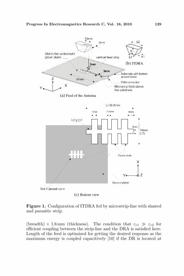
This paper presents a more compact DRA of novel geometry,isosceles trapezoidal shape with wide band response for applicationsthat cover frequency ranges for WLAN 2.4, WiBro and DMB. Theantenna gives moderately high gain as high as 4.17 dBi. The antenna isfed by a microstrip line and the ground is modified as shown in Figure 1.The modification in the ground plane is made by making a slot in thedesired shape for getting an optimum bandwidth and radiation pattern.The shape of the slot is optimized as in the form of a fish bone asshown in Figure 1 and it is symmetrically made in the ground planewith respect to the DRA for getting a symmetrical radiation pattern.Increased bandwidth is the result of merging multiple resonancesoriginating in a close neighborhood by the combined effect of theslot provided in the ground plane and the presence of parasitic strip.Maximum bandwidth for the antenna is obtained in the useful rangewith cross slot length of 16 mm (∼ λ0). It can be seen from Figure 5that the ground plane slots have a positive effect on increasing thebandwidth of the antenna and reducing the resonance frequency. Crossslot length has a larger effect than the long slot length in loweringresonance frequency that in turn results in a compact antenna withwide band response. The proposed geometry has the advantage inthat it covers lower bands including the above mentioned applicationbands, when compared to other proposed wideband DRA structureswith parasitic strip [5, 11–13].
2. GEOMETRY OF THE ANTENNA
Antenna structure is shown in Figure 1. An isosceles trapezoidal DRAof permittivity εr1 = 20.8, bases b1 = 15.4mm, b2 = 30.8mm, heighth = 13.3mm and thickness h1 = 13 mm is fed by a 50Ω transmissionline of 66.5mm (length) × 3mm (width) fabricated on a microwavesubstrate of permittivity εr2 = 4 with size 115mm (length)× 115mm
Progress In Electromagnetics Research C, Vol. 16, 2010 129
(a) Feed of the Antenna
(b) ITDRA
(c) Bottom view
Figure 1. Configuration of ITDRA fed by microstrip-line with slantedand parasitic strip.
(breadth) × 1.6mm (thickness). The condition that εr1 À εr2 forefficient coupling between the strip-line and the DRA is satisfied here.Length of the feed is optimized for getting the desired response as themaximum energy is coupled capacitively [10] if the DR is located at

130 Gopakumar and Mathew
the point of maximum electric field on the feed.A metallic strip with a height and width optimized as 9.5 mm and
3mm respectively is adhered to the slanting surface at the feed sideof the TDRA and is connected electrically to the feed line at a lengthL = 16.7mm from its open end as shown in Figure 1(a). Without theslanted strip the intensity of radiation pattern is seen to be dominatedtowards the feed side. A parasitic strip on the top surface of theantenna with an offset of 5.9 mm from the center of the surface with alength and width optimized as 13 mm and 3mm respectively is adheredfor obtaining maximum band width. The angle of inclination of thisstrip with reference to the micro-strip feed line is also optimized as 10
.
Loading effect of the top parasitic strip helps to reduce the Q of theantenna and thereby increasing its impedance band width to a certainextend.
The ground plane is modified as shown in Figure 1 by makinga slot in the form of a fish bone with a long and cross rectangularslots. The long slot is kept under and along the micro strip-line witha dimension of L1 = 30.8mm (length) × 3mm (breadth) and withan offset of 41.7 mm from the feed position. The cross slots have thedimensions of L2 = 16mm (length) × B2 = 4 mm (breadth) and areseparated among them by a distance of 2.5 mm. The entire slot iskept symmetrical with respect to the position of the DRA for gettingsymmetrical radiation pattern.
Antenna measurements are performed with HP 8510C vectornetwork analyzer. The reflection (S11), impedance (Z), radiation (S12)characteristics and gain of the DRA are measured and discussed in thefollowing section.
3. RESULTS AND DISCUSSIONS
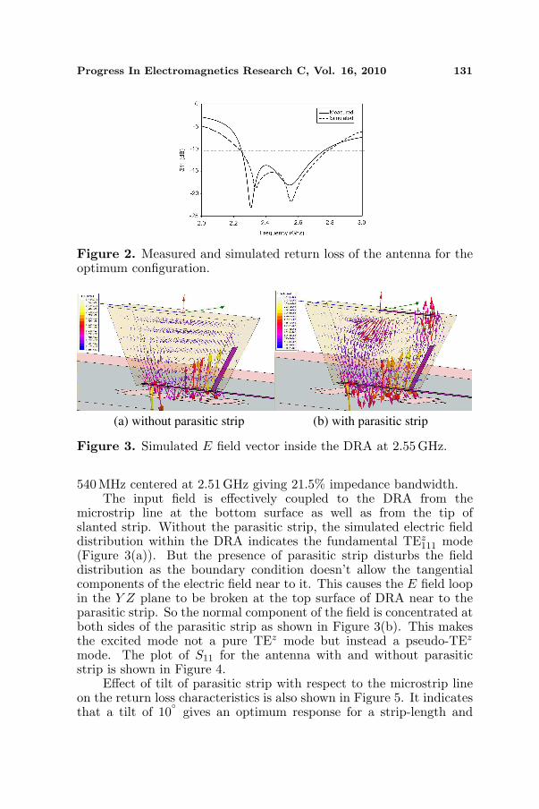
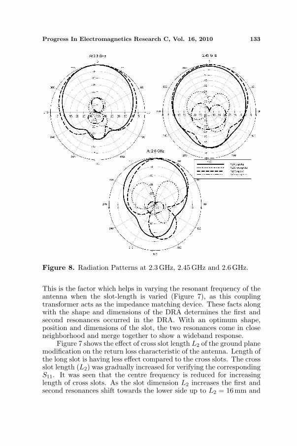
Measured and simulated plot of return loss (|S11|), of the DRA arecompared in Figure 2 and shown that they are in good agreement.Effect of ground plane modification on the return loss characteristicsof the antenna is shown in Figure 6. It is seen that the modificationof ground plane changes the radiation characteristics of the antenna.It is apparent from the figure that long slot has the tendency to shiftthe resonances towards upper side of frequency whereas the cross slotsshift them towards the lower side. When both long and cross slotsare introduced together, two resonances occurred, one is at slightlylower side and the second is on far upper side of the original resonancethat created when no modification on ground plane is made. So inthe proposed antenna these two resonances are developed in the closeneighborhood so as to merge together to form a wide band response of
Progress In Electromagnetics Research C, Vol. 16, 2010 131
Figure 2. Measured and simulated return loss of the antenna for theoptimum configuration.
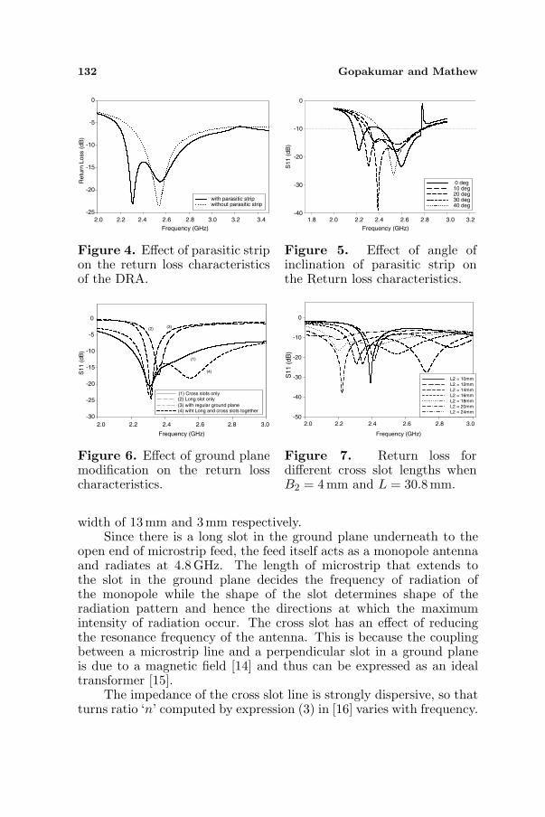
(a) without parasitic strip (b) with parasitic strip
Figure 3. Simulated E field vector inside the DRA at 2.55GHz.
540MHz centered at 2.51 GHz giving 21.5% impedance bandwidth.The input field is effectively coupled to the DRA from the
microstrip line at the bottom surface as well as from the tip ofslanted strip. Without the parasitic strip, the simulated electric fielddistribution within the DRA indicates the fundamental TEz
111 mode(Figure 3(a)). But the presence of parasitic strip disturbs the fielddistribution as the boundary condition doesn’t allow the tangentialcomponents of the electric field near to it. This causes the E field loopin the Y Z plane to be broken at the top surface of DRA near to theparasitic strip. So the normal component of the field is concentrated atboth sides of the parasitic strip as shown in Figure 3(b). This makesthe excited mode not a pure TEz mode but instead a pseudo-TEz
mode. The plot of S11 for the antenna with and without parasiticstrip is shown in Figure 4.
Effect of tilt of parasitic strip with respect to the microstrip lineon the return loss characteristics is also shown in Figure 5. It indicatesthat a tilt of 10
gives an optimum response for a strip-length and
132 Gopakumar and Mathew
Frequency (GHz)
2.0 2.2 2.4 2.6 2.8 3.0 3.2 3.4
Retu
rn L
oss (
dB
)
-25
-20
-15
-10
-5
0
with parasitic strip without parasitic strip
Figure 4. Effect of parasitic stripon the return loss characteristicsof the DRA.
-40
-30
-20
-10
0
0 deg10 deg20 deg30 deg40 deg
Frequency (GHz)
2.0 2.2 2.4 2.6 2.8 3.0 3.21.8
S11 (
dB
)
Figure 5. Effect of angle ofinclination of parasitic strip onthe Return loss characteristics.
S1
1 (
dB
)
-30
-25
-20
-15
-10
-5
0
(1) Cross slots only(2) Long slot only
(3) with regular ground plane(4) wiht Long and cross slots together
(4)
(1)
(2) (3)
Frequency (GHz)
2.0 2.2 2.4 2.6 2.8 3.0
Figure 6. Effect of ground planemodification on the return losscharacteristics.
S11 (
dB
)
-50
-40
-30
-20
-10
0
L2 = 10mm
L2 = 12mm
L2 = 14mm
L2 = 16mm
L2 = 18mm
L2 = 20mm
L2 = 24mm
2.0 2.2 2.4 2.6 2.8 3.0
Frequency (GHz)
Figure 7. Return loss fordifferent cross slot lengths whenB2 = 4 mm and L = 30.8mm.
width of 13mm and 3 mm respectively.Since there is a long slot in the ground plane underneath to the
open end of microstrip feed, the feed itself acts as a monopole antennaand radiates at 4.8 GHz. The length of microstrip that extends tothe slot in the ground plane decides the frequency of radiation ofthe monopole while the shape of the slot determines shape of theradiation pattern and hence the directions at which the maximumintensity of radiation occur. The cross slot has an effect of reducingthe resonance frequency of the antenna. This is because the couplingbetween a microstrip line and a perpendicular slot in a ground planeis due to a magnetic field [14] and thus can be expressed as an idealtransformer [15].
The impedance of the cross slot line is strongly dispersive, so thatturns ratio ‘n’ computed by expression (3) in [16] varies with frequency.
Progress In Electromagnetics Research C, Vol. 16, 2010 133
Figure 8. Radiation Patterns at 2.3 GHz, 2.45 GHz and 2.6GHz.
This is the factor which helps in varying the resonant frequency of theantenna when the slot-length is varied (Figure 7), as this couplingtransformer acts as the impedance matching device. These facts alongwith the shape and dimensions of the DRA determines the first andsecond resonances occurred in the DRA. With an optimum shape,position and dimensions of the slot, the two resonances come in closeneighborhood and merge together to show a wideband response.
Figure 7 shows the effect of cross slot length L2 of the ground planemodification on the return loss characteristic of the antenna. Length ofthe long slot is having less effect compared to the cross slots. The crossslot length (L2) was gradually increased for verifying the correspondingS11. It was seen that the centre frequency is reduced for increasinglength of cross slots. As the slot dimension L2 increases the first andsecond resonances shift towards the lower side up to L2 = 16mm and
134 Gopakumar and Mathew
further the second resonance disappears while the first resonance stillshifts towards lower side. It is noted that a strong matching resonanceoccurs for L2 = 20mm with a weak resonance on either side of thedimension.
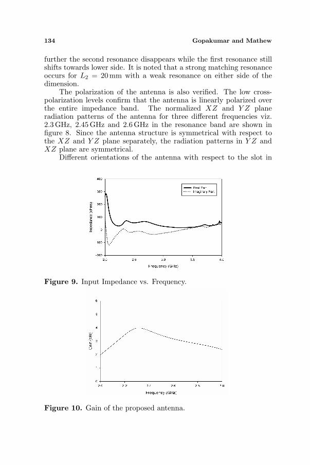
The polarization of the antenna is also verified. The low cross-polarization levels confirm that the antenna is linearly polarized overthe entire impedance band. The normalized XZ and Y Z planeradiation patterns of the antenna for three different frequencies viz.2.3GHz, 2.45 GHz and 2.6 GHz in the resonance band are shown infigure 8. Since the antenna structure is symmetrical with respect tothe XZ and Y Z plane separately, the radiation patterns in Y Z andXZ plane are symmetrical.
Different orientations of the antenna with respect to the slot in
Figure 9. Input Impedance vs. Frequency.
Figure 10. Gain of the proposed antenna.
Progress In Electromagnetics Research C, Vol. 16, 2010 135
ground plane and microstrip line feed is also tried out for studies andverified that the proposed one gives the best result. Plot of inputimpedance against frequency which is shown in Figure 9 confirm thatthe impedance matching between the feed and the antenna is occurredat frequencies corresponding to the resonant modes.
The measured gain of the antenna is shown in Figure 10. Theantenna has a peak gain of 4.17 dBi at 2.19 GHz and a least of 2.2 dBiat 2 GHz with an average value of 3.19 dBi.
4. CONCLUSION
A wideband Dielectric Resonator Antenna with a novel geometry hasbeen proposed and developed. The antenna offers an impedanceband width of 21.5% centered at 2.51 GHz and linear polarization ofradiation throughout the band. The wide impedance band width isthe result of dual radiating modes which are excited in close vicinityas a result of the parasitic strip and the slot in ground plane. Thiswideband response is in relatively lower frequency range which includesimportant application bands viz. ISM: Bluetooth/WLAN 2.4/Wibree(802.11 b/g/n)/ZigBee, WiBro and DMB. Radiation patterns arefound to be broad over the entire bandwidth with good cross-polarization levels.
REFERENCES
1. Lo, H. Y., K. W. Leung, K. M. Luk, and E. K. N. Yung, “Lowprofile equilateral-triangular dielectric resonator antenna of veryhigh permittivity,” Electronics Letters, Vol. 35, 2164–2166, 1999.
2. Petosa, A., A. Ittipiboon, Y. M. M. Antar, D. Roscoe, andM. Cuhaci, “Recent advances in dielectric resonator antennastechnology,” IEEE Antennas Propagat. Mag., Vol. 40, 35–48,1998.
3. Hamsakutty, V., A. V. Praveen Kumar, J. Yohannan, andK. T. Mathew, “Coaxial fed hexagonal dielectric resonatorantenna for circular polarization,” Microwave and OpticalTechnology Letters, Vol. 48, No. 3, 581–582, Mar. 2006.
4. Wei, L. T. and S. J. Shiun, “Wideband dielectric resonatorantenna with parasitic strip,” IEEE Appl. Comput. Electromagn.Soc. Int. Conf., 376–379, Apr. 2005.
5. Li, B. and K. W. Leung, “Strip-fed rectangular dielectric resonatorantennas with/without a parasitic patch,” IEEE Trans. AntennasPropag., Vol. 53, No. 7, 2200–2207, Jul. 2005.
136 Gopakumar and Mathew
6. Buerkle, A., K. Sarabandi, and H. Mosallaei, “Compact slotand dielectric resonator antenna with dual-resonance, broadbandcharacteristics,” IEEE Trans. Antennas Propag., Vol. 53, No. 3,1020–1027, Mar. 2005.
7. Shum, S. M. and K. M. Luk, “Characteristics of dielectric ringresonator antenna with an air gap,” Electron. Lett., Vol. 30, No. 4,277–278, Feb. 1994.
8. Ittipiboon, A., A. Petosa, D. Roscoe, and M. Cuhaci, “Aninvestigation of a novel broadband dielectric resonator antenna,”APS Int. Symp., Vol. 3, 2038–2041, Jul. 1996.
9. Kranenberg, R. A. and S. A. Long, “Microstrip transmission lineexcitation of dielectric resonator antennas,” Electronics Letters,Vol. 24, No. 18, 1156–1157, 1988.
10. Leung, K. W., K. Y. Chow, K. M. Luk, and E. K. N. Yung, “Lowprofile circular disk DR antenna of very high permittivity excitedby a microstripline,” Electronics Letters, Vol. 33, No. 12, 1004–1005, 1997.
11. Praveen Kumar, A. V., V. Hamsakutty, J. Yohannan, andK. T. Mathew, “Microstripline fed cylindrical dielectric rresonatorantenna with a coplanar parasitic strip,” Progress In Electromag-netic Research, Vol. 60, 143–152, 2006.
12. Jamaluddin, M. H., R. Gillard, R. Sauleau, P. Dumon, andL. Le Coq, “Reflectarray element based on strip-loaded dielectricresonator antenna,” Electronics Letters, Vol. 44, No. 11, 664–665,May 22, 2008.
13. Gao, Y., B.-L. Ooi, and M.-S. Leong, “Dual-band hybrid dielectricresonator antenna for WLAN,” IEEE Antennas and PropagationSociety International Symposium, 1–4, Jul. 5–11, 2008.
14. Xiao, F., Y. Nakada, K. Murano, and Y. Kami, “Crosstalkanalysis model for traces crossing split ground plane and itsreduction by stitching capacitor,” IEICE Trans. Electronics,Vol. 11, 885–893, 2006.
15. Hitoshi, N., M. Kimitoshi, F. Xiao, and K. Yoshio, “Circuitmodel for two parallel microstrip lines on slotted ground plane,”International Symposium on Electromagnetic Compatibility, EMC2007, 130–133, Oct. 23–26, 2007.
16. Caloz, C., H. Okabe, T. Iwai, and T. Itoh, “A simple and accuratemodel for microstrip structures with slotted ground plane,” IEEEMicrowave and Wireless Components Letters, Vol. 14, No. 3, 127–129, Mar. 2004.


![[PPT]Isosceles, Equilateral, and Right Triangles · Web viewIsosceles, Equilateral, and Right Triangles Chapter 4.6 Isosceles Triangle Theorem Isosceles The 2 Base s are Base angles](https://img.pdfslide.us/doc/110x75/5ab09a077f8b9ac66c8b7356/pptisosceles-equilateral-and-right-triangles-viewisosceles-equilateral-and.jpg)