Embed Size (px)
Citation preview
SCRATCH AND RED RAW: THE RED COLOR WORKFLOW
Written by Mike Most
ASSIMILATE WHITE PAPER
2
SCRATCH and Red Raw: The Red Color Workflow
The Red camera represents a new approach to motion image capture that relies on post processing, rather than in-camera processing, to
deliver images that are appropriate for use in both video and film finishing formats. The files that are written directly by the camera
represent - in compressed form - the actual data captured by the Mysterium sensor, without any manipulation for specific display systems.
Because of this, when working with Red images it is necessary to understand some of the basic principles of working with digital images in
order to determine the proper path for an intended delivery format.
Without going into unnecessary details, the Mysterium sensor in the Red cameras is a single sensor that captures color images by means of
a color filter array that is superimposed on the individual pixel sites on the sensor. The particular pattern that is used is called a Bayer
pattern, and consists of alternating rows, each of which has a combination of either red and green pixels (i.e., GRGR etc.), or blue and green
pixels (i.e., BGBG etc.). In order to create a “normal” RGB image, a process called a Debayer (also referred to as “demosaic”) is invoked,
which uses some rather complex math to predict what each of the individual pixel sites would contain in all three color components by
combining the values of the surrounding pixels for each of the colors not directly represented by each individual pixel. A good debayering
algorithm can be very accurate, and the algorithm used by Red is very good indeed. Since the red, green, and blue filters used on the
sensor are not absolutely “pure,” and the tiny lenses that focus each filter’s light on the image element itself are not perfect, there is a
certain amount of “crosstalk” that occurs between the values of each pixel - in other words, the red pixels also contain a certain amount of
blue and green, the blue pixels contain a certain amount of red and green, and the green pixels contain a certain amount of red and blue.
The debayering algorithm is specifically designed by Red to account for these variations, based on their specific sensor characteristics. The
sensor also has a “native” white point, that is, a specific point in the color spectrum that is considered to be white. In order to achieve a
more “pure” - and thus accurate to the actual scene – image on a specific type of display, a color matrix is then used that alters each
component by adding or subtracting a bit of the other two components, based on the characteristics of the intended display, in particular,
the display’s specific white point. In the world of Red, this color matrix is usually identified using the term Color Space.
Color space, put simply, is a mathematical description of color. It is used to represent color in ways that are appropriate to the display
device being used, and to account for the range of colors that the particular device is capable of achieving (the “color gamut”). When
working with Red images, Red has predefined a few color spaces for use when converting RAW images to RGB images. These color space
models are basically intended to provide color values in the converted image that are appropriate for various display methods, based on the
general characteristics of those displays (in particular their white point), and their specific color gamut. Essentially, the values that are the
result of the debayering process are further altered by each of the color space settings (in both value and saturation) to achieve more
accuracy to the “real world” colors that were present when the images were captured by the sensor, based on the characteristics of the
intended display system. At this point, the color space choices (they are actually color matrixes, and can be described by either term), and
their effects on the image, that are currently offered by Red are:
At this point, the best choices for most projects seem to be Camera RGB and Redspace, with Camera RGB being preferred for most film
projects, for reasons we will discuss shortly.
>> Color Space
Camera RGB: This matrix passes the RGB values as described above and does not modify them based on any particular display technology.
Rec709: This matrix alters the resulting RGB values to, in theory, properly display an accurate representation on an HD video display. It also
seems to add quite a bit of saturation, and because of that, is rarely used.
Redspace: This matrix appears to be similar to Camera RGB, but with a mild saturation boost
© ASSIMILATE, Inc. June 2009 Information contained herein may be subject to change without prior notice
3
SCRATCH and Red Raw: The Red Color Workflow
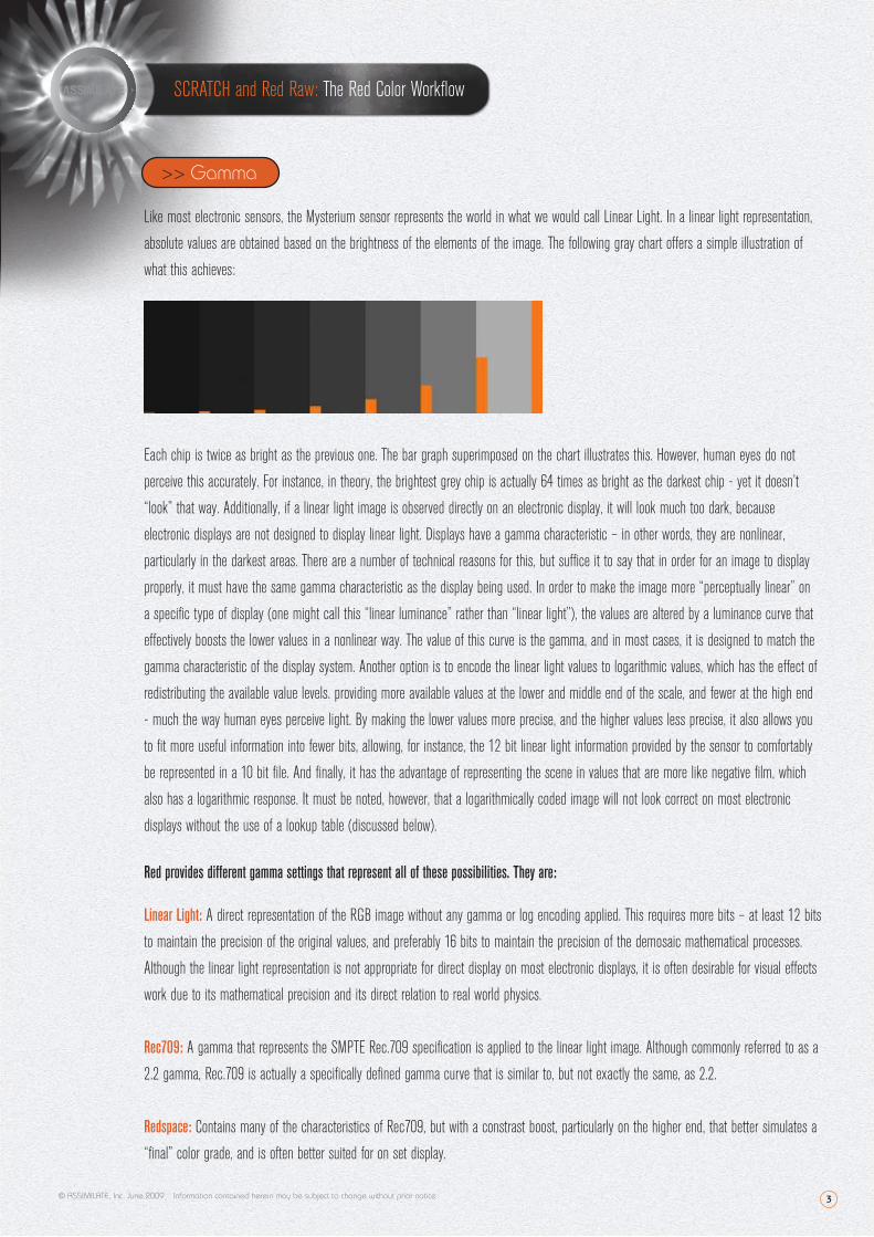
Like most electronic sensors, the Mysterium sensor represents the world in what we would call Linear Light. In a linear light representation,
absolute values are obtained based on the brightness of the elements of the image. The following gray chart offers a simple illustration of
what this achieves:
Each chip is twice as bright as the previous one. The bar graph superimposed on the chart illustrates this. However, human eyes do not
perceive this accurately. For instance, in theory, the brightest grey chip is actually 64 times as bright as the darkest chip - yet it doesn’t
“look” that way. Additionally, if a linear light image is observed directly on an electronic display, it will look much too dark, because
electronic displays are not designed to display linear light. Displays have a gamma characteristic – in other words, they are nonlinear,
particularly in the darkest areas. There are a number of technical reasons for this, but suffice it to say that in order for an image to display
properly, it must have the same gamma characteristic as the display being used. In order to make the image more “perceptually linear” on
a specific type of display (one might call this “linear luminance” rather than “linear light”), the values are altered by a luminance curve that
effectively boosts the lower values in a nonlinear way. The value of this curve is the gamma, and in most cases, it is designed to match the
gamma characteristic of the display system. Another option is to encode the linear light values to logarithmic values, which has the effect of
redistributing the available value levels. providing more available values at the lower and middle end of the scale, and fewer at the high end
- much the way human eyes perceive light. By making the lower values more precise, and the higher values less precise, it also allows you
to fit more useful information into fewer bits, allowing, for instance, the 12 bit linear light information provided by the sensor to comfortably
be represented in a 10 bit file. And finally, it has the advantage of representing the scene in values that are more like negative film, which
also has a logarithmic response. It must be noted, however, that a logarithmically coded image will not look correct on most electronic
displays without the use of a lookup table (discussed below).
Red provides different gamma settings that represent all of these possibilities. They are:
Linear Light: A direct representation of the RGB image without any gamma or log encoding applied. This requires more bits – at least 12 bits
to maintain the precision of the original values, and preferably 16 bits to maintain the precision of the demosaic mathematical processes.
Although the linear light representation is not appropriate for direct display on most electronic displays, it is often desirable for visual effects
work due to its mathematical precision and its direct relation to real world physics.
Rec709: A gamma that represents the SMPTE Rec.709 specification is applied to the linear light image. Although commonly referred to as a
2.2 gamma, Rec.709 is actually a specifically defined gamma curve that is similar to, but not exactly the same, as 2.2.
Redspace: Contains many of the characteristics of Rec709, but with a constrast boost, particularly on the higher end, that better simulates a
“final” color grade, and is often better suited for on set display.
>> Gamma
© ASSIMILATE, Inc. June 2009 Information contained herein may be subject to change without prior notice
4
SCRATCH and Red Raw: The Red Color Workflow
PDLog685 and PDLog985: The image is encoded to a logarithmic curve that is designed to mimic the Cineon curve, based on film density.
Redlog: The image is encoded to a logarithmic curve that is much milder than the Cineon curve, and better represents the linear values
obtained from the sensor, designed to be stored in a 10 bit file. The entire range of 10 bit values from 0 through 1023 is used. The curve is
designed so that the precision of the darkest 8 stops of information is retained, and although there is some loss of precision in the upper 4
stops, it is not significant. This setting is often used for transcodes for finishing work, as it best represents the original information with
minimal loss, and can be used directly for “video” style color grading without requiring the use of a LUT.
ASSIMILATE SCRATCH supplies methods for using all of these approaches, but since SCRATCH can read the Red’s native files (the “R3d”
files) directly, they are organized in a different way than they are in Red’s own conversion tools. In addition, ASSIMILATE has introduced
more comprehensive yet simpler settings (RedRaw Lin and RedRaw Log) that yield proper results with less user intervention. Depending
upon the needs of the project and its delivery requirements, different methods can be used.
As we’ve already noted, many people refer to gamma encoded images as “linear.” While this is not technically correct, it does serve to
differentiate between values that are based on a linear representation and values based on a logarithmic representation. Even though our
eyes represent light logarithmically, electronic displays do not. An image that is “linear” - i.e., gamma encoded - will appear “correct” to our
eyes when seen on a display that matches that gamma. An image that is encoded logarithmically, however, will not look correct because the
display is not logarithmic (it will look very light, and lack contrast). For this reason, when dealing with images intended purely for electronic
displays - and that can mean anything from a CRT monitor to an LCD or plasma based monitor, or even an electronic projector - we
generally want to use images that are gamma encoded, with the gamma matching that of the display. The digital intermediate process for
film recording, however, often demands a different approach. Film recorders expect logarithmically encoded images - the standard Cineon
curve, in most cases - as their input. For a digital intermediate project - especially one that involves film as a source - it is advantageous to
work with logarithmically coded images throughout the process. In order to do that, the use of a lookup table (LUT) is required. A lookup
table basically takes a set of input values and converts them, based on a precomputed table, into different output values. Simple lookup
tables, often called “1D” LUTs, are often used for conversions such as linear values to logarithmic values. The differences between electronic
displays and the film process, however, are more significant, involving different saturation levels and different color gamuts. To visually
represent a film image on an electronic display, one needs to use a LUT that can take into consideration these differences. This requires
what is usually called a “3D” LUT, which contains values that map not only the single individual levels for each red, green and blue input, but
also takes into account the influence of the other two color components in the resulting output level. Creating 3D LUTs usually involves
profiling both the display being used, and the characteristics of the specific film stocks, recorder, and lab processing involved. There are
various vendors who supply the tools and expertise for this, including Rising Sun Research (now owned by Cinetal, their product is called
Cinespace) and Filmlight (their product is called Truelight). For true accuracy in a film targeted digital intermediate process, properly derived
3D LUTs are imperative.
It is, of course, also possible to convert gamma encoded values to logarithmic values at the end of a color grading process. This requires an
“inverse LUT,” which is often provided by film recording vendors using either their own approach, or through software provided by the film
>> Working in “Linear” vs. Working in Log
© ASSIMILATE, Inc. June 2009 Information contained herein may be subject to change without prior notice
5
SCRATCH and Red Raw: The Red Color Workflow
recorder manufacturer. For those using an ArriLaser for film recording, Arri supplies their ArriCube system for converting gamma encoded
images conforming to the HD video recommendation (Rec.709) directly to their Cineon equivalents. This allows one to work with electronic
images in their “native” form without restricting the colors available during the DI process to those normally represented by a film process.
Up until this point, film has been the dominant medium for theatrical feature distribution world wide. Because of this, film has been
considered the “primary deliverable” product of the digital intermediate process. As digital cinema is taking hold, however, this is being
re-thought, and it’s entirely possible that digital cinema and electronic deliverables will likely become the primary target in the future.
Performing the color grading on a Red project in gamma corrected linear space has some very specific advantages. First, the color pallette
that was captured is not being altered by the needs of the film process during the creative decision making. Second, the need for a 3D LUT
to simulate the film print is removed. Third, the ability to make selective changes to the image is increased. This is due to a number of
factors. When working with logarithmic images, the effects of any changes are enhanced due to the additional contrast added downstream
by the 3D LUT. The ranges of the “traditional” color controls - designed to work on linear images - have less delineation, minimizing specific
control of the dark areas, for instance. In addition the natural increase in saturation in the gamma encoded image allows for more control in
terms of secondary color isolations and keying operations. Fortunately, SCRATCH gives the user options for working in the manner that’s
most appropriate, regardless of the situation.
SCRATCH has the ability to read R3d files directly, with no transcoding necessary and no rendering necessary. Because of this, workflows
are greatly streamlined. There is no need to do anything to the R3d files prior to ingest into SCRATCH other than copy them to locally visible
storage - which can, of course, be internal, external, network, or SAN storage. Although it is sometimes helpful to retain the .RDM and .RDC
folder structures as written by the Red camera, the only files necessary for SCRATCH are the R3d files, as the Quicktime wrappers are not
used. Conforming operations are done directly from the R3d files, which can be played in real time on most modern PC hardware. This can
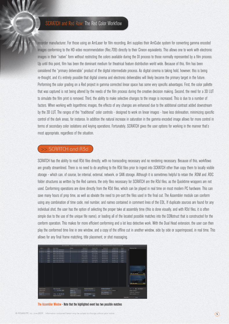
save many hours of prep time, as well as obviate the need to pre-sort the files used in the final cut. The Assembler module can conform
using any combination of time code, reel number, and names contained in comment lines of the EDL. If duplicate sources are found for any
individual shot, the user has the option of selecting the proper take at assembly time (this is done visually, and with R3d files, it is often
simple due to the use of the unique file name), or loading all of the located possible matches into the CONstruct that is constructed for the
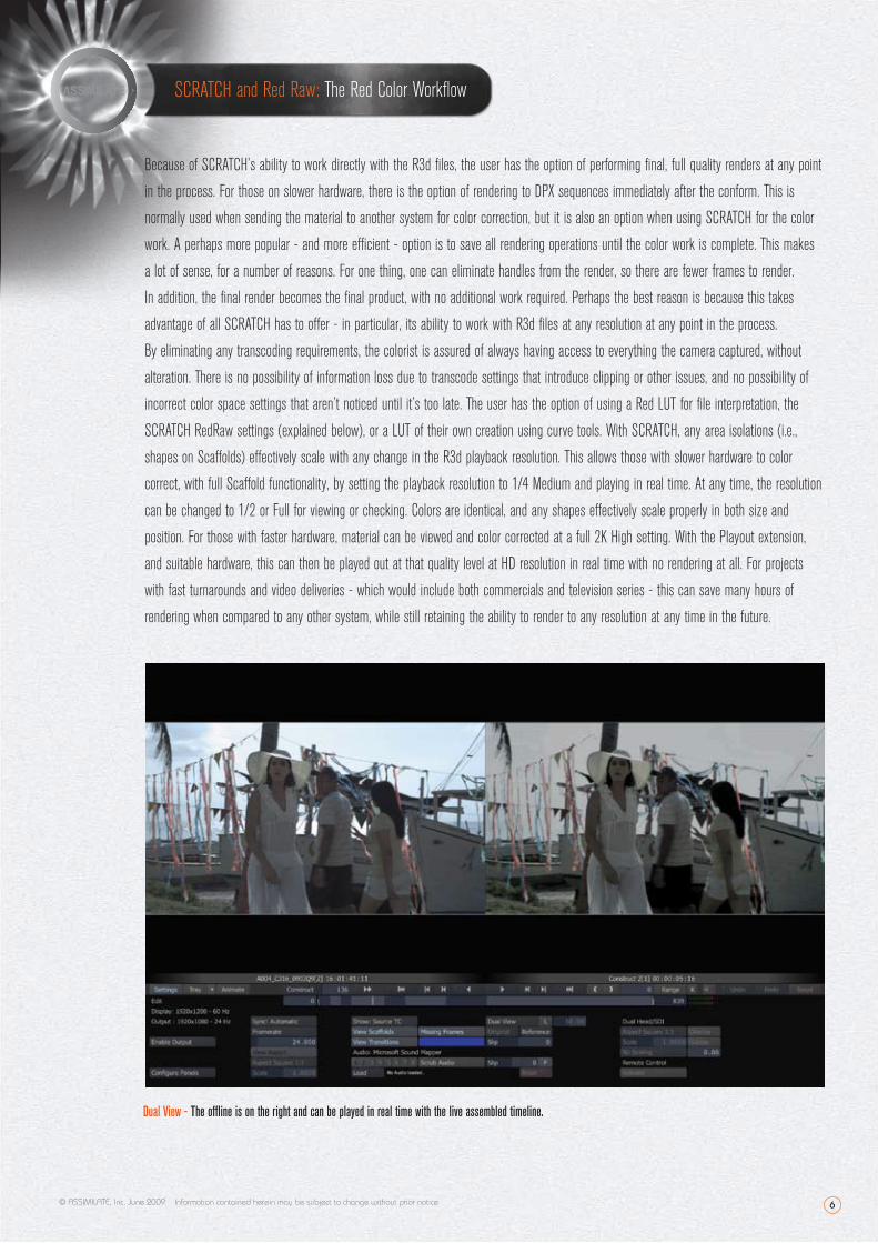
conform operation. This makes for more efficient conforming and a lot less detective work. With the Dual Head extension, the user can then
play the conformed time line in one window, and a copy of the offline cut in another window, side by side or superimposed, in real time. This
allows for any final frame matching, title placement, or shot massaging.
>> SCRATCH and R3d
© ASSIMILATE, Inc. June 2009 Information contained herein may be subject to change without prior notice
The Assembler Window - Note that the highlighted event has two possible matches
6
SCRATCH and Red Raw: The Red Color Workflow
Because of SCRATCH’s ability to work directly with the R3d files, the user has the option of performing final, full quality renders at any point
in the process. For those on slower hardware, there is the option of rendering to DPX sequences immediately after the conform. This is
normally used when sending the material to another system for color correction, but it is also an option when using SCRATCH for the color
work. A perhaps more popular - and more efficient - option is to save all rendering operations until the color work is complete. This makes
a lot of sense, for a number of reasons. For one thing, one can eliminate handles from the render, so there are fewer frames to render.
In addition, the final render becomes the final product, with no additional work required. Perhaps the best reason is because this takes
advantage of all SCRATCH has to offer - in particular, its ability to work with R3d files at any resolution at any point in the process.
By eliminating any transcoding requirements, the colorist is assured of always having access to everything the camera captured, without
alteration. There is no possibility of information loss due to transcode settings that introduce clipping or other issues, and no possibility of
incorrect color space settings that aren’t noticed until it’s too late. The user has the option of using a Red LUT for file interpretation, the
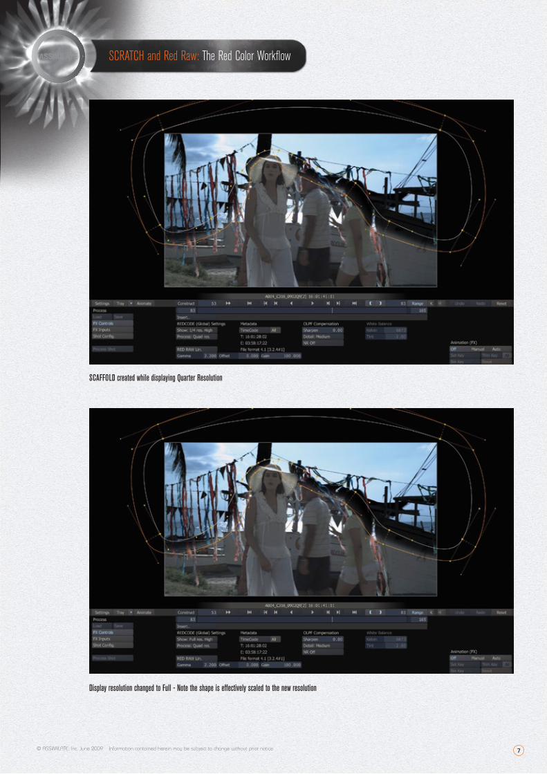
SCRATCH RedRaw settings (explained below), or a LUT of their own creation using curve tools. With SCRATCH, any area isolations (i.e.,
shapes on Scaffolds) effectively scale with any change in the R3d playback resolution. This allows those with slower hardware to color
correct, with full Scaffold functionality, by setting the playback resolution to 1/4 Medium and playing in real time. At any time, the resolution
can be changed to 1/2 or Full for viewing or checking. Colors are identical, and any shapes effectively scale properly in both size and
position. For those with faster hardware, material can be viewed and color corrected at a full 2K High setting. With the Playout extension,
and suitable hardware, this can then be played out at that quality level at HD resolution in real time with no rendering at all. For projects
with fast turnarounds and video deliveries - which would include both commercials and television series - this can save many hours of
rendering when compared to any other system, while still retaining the ability to render to any resolution at any time in the future.
© ASSIMILATE, Inc. June 2009 Information contained herein may be subject to change without prior notice
Dual View - The offline is on the right and can be played in real time with the live assembled timeline.
7
SCRATCH and Red Raw: The Red Color Workflow
© ASSIMILATE, Inc. June 2009 Information contained herein may be subject to change without prior notice
SCAFFOLD created while displaying Quarter Resolution
Display resolution changed to Full - Note the shape is effectively scaled to the new resolution
8
SCRATCH and Red Raw: The Red Color Workflow
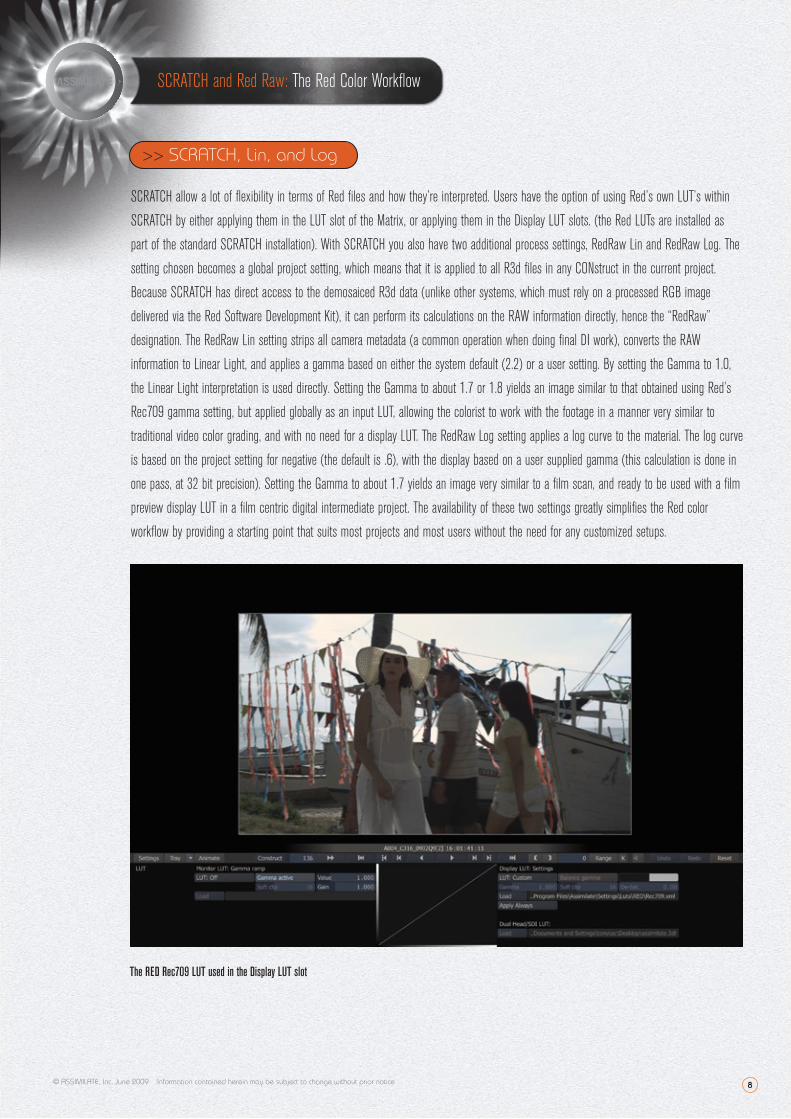
SCRATCH allow a lot of flexibility in terms of Red files and how they’re interpreted. Users have the option of using Red’s own LUT’s within
SCRATCH by either applying them in the LUT slot of the Matrix, or applying them in the Display LUT slots. (the Red LUTs are installed as
part of the standard SCRATCH installation). With SCRATCH you also have two additional process settings, RedRaw Lin and RedRaw Log. The
setting chosen becomes a global project setting, which means that it is applied to all R3d files in any CONstruct in the current project.
Because SCRATCH has direct access to the demosaiced R3d data (unlike other systems, which must rely on a processed RGB image
delivered via the Red Software Development Kit), it can perform its calculations on the RAW information directly, hence the “RedRaw”
designation. The RedRaw Lin setting strips all camera metadata (a common operation when doing final DI work), converts the RAW
information to Linear Light, and applies a gamma based on either the system default (2.2) or a user setting. By setting the Gamma to 1.0,
the Linear Light interpretation is used directly. Setting the Gamma to about 1.7 or 1.8 yields an image similar to that obtained using Red’s
Rec709 gamma setting, but applied globally as an input LUT, allowing the colorist to work with the footage in a manner very similar to
traditional video color grading, and with no need for a display LUT. The RedRaw Log setting applies a log curve to the material. The log curve
is based on the project setting for negative (the default is .6), with the display based on a user supplied gamma (this calculation is done in
one pass, at 32 bit precision). Setting the Gamma to about 1.7 yields an image very similar to a film scan, and ready to be used with a film
preview display LUT in a film centric digital intermediate project. The availability of these two settings greatly simplifies the Red color
workflow by providing a starting point that suits most projects and most users without the need for any customized setups.
>> SCRATCH and R3d>> SCRATCH, Lin, and Log
The RED Rec709 LUT used in the Display LUT slot
© ASSIMILATE, Inc. June 2009 Information contained herein may be subject to change without prior notice
9
SCRATCH and Red Raw: The Red Color Workflow
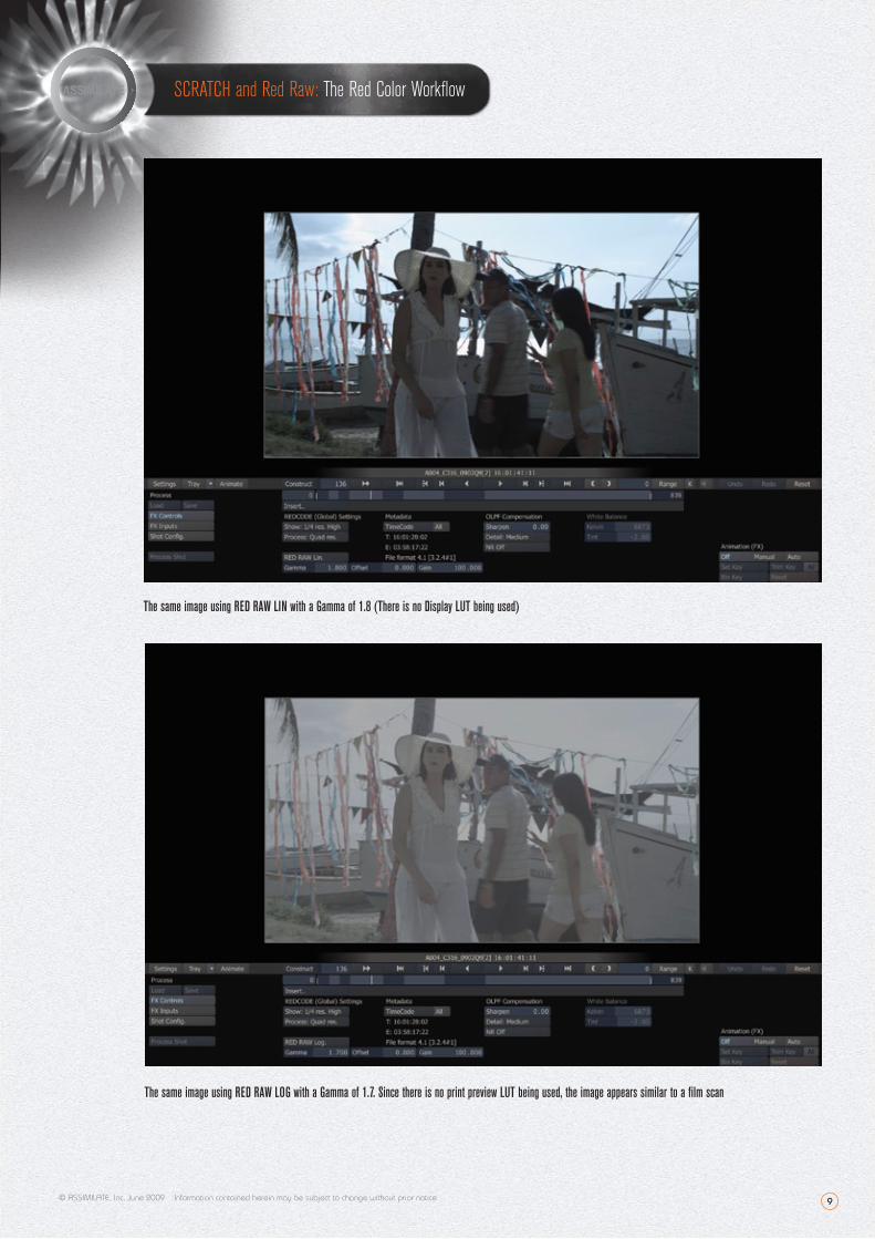
The same image using RED RAW LIN with a Gamma of 1.8 (There is no Display LUT being used)
The same image using RED RAW LOG with a Gamma of 1.7. Since there is no print preview LUT being used, the image appears similar to a film scan
© ASSIMILATE, Inc. June 2009 Information contained herein may be subject to change without prior notice
10 © ASSIMILATE, Inc. June 2009 Information contained herein may be subject to change without prior notice
SCRATCH and Red Raw: The Red Color Workflow
>> The SCRATCH Advantage
Much has been said and written about the Red camera and its ability to deliver extremely high quality images at a very reasonable cost.
Much has also been said and written about the allegedly complex workflows it has engendered. To be sure, there is much about Red that is
unique - its 4K resolution, its use of Redcode compression and RAW data to allow high resolution imagery that can be used on commodity
equipment and storage, and its overall bang for the buck. Many Red projects seem to be posted in many different ways, and in some ways
that is one of its strengths - the ability to scale its workflow requirements to suit almost anything from a Mac laptop to a high end DI suite.
In the world of finishing, there are many choices - but none of them bring all of the advantages for Red originated projects that SCRATCH
does. From its ability to play R3d files directly, with full color correction capabilities, in real time, to its ability to conform directly from the
R3d files, to its ability to compare the conformed timeline directly to an offline while playing both in real time, to its ability to play out the
color corrected final material at up to 2K resolution with no rendering, to its RedRaw settings that simplify the color correction process, no
system currently available has a level of support for Red projects that can match ASSIMILATE SCRATCH.
Project Name: Festival Nacional de Cine de Margarita 2008 (National Film Festival of Margarita 2008)
Client: Centro Nacional Autónomo de Cinematografía
Production Company: Cooperativa Mas Producciones
Director: Henry Páez
Director de Fotografía (DP): Alejandro García Wiedeman
Scratch en: Produrama
Laboratorio (FL): Futuro Films
Written by: Mike Most (Colorist/Technologist)
>> Credits & Acknowledgements