Embed Size (px)
Citation preview


A Web Engineering Approach for A Web Engineering Approach for A Web Engineering Approach for A Web Engineering Approach for the Development of Businessthe Development of Businessthe Development of Businessthe Development of Business----
Process Driven Web ApplicationsProcess Driven Web ApplicationsProcess Driven Web ApplicationsProcess Driven Web Applications
Victoria Torres BoschVictoria Torres BoschVictoria Torres BoschVictoria Torres Bosch
Department of Information Systems and Computation
Technical University of Valencia
A thesis submitted in partial fulfilment of the requirements for the degree of Doctor of Philosophy in Computer Science
Supervisor: Dr. Vicente Pelechano Ferragud
July 2008


Members of the Thesis Committee:
Dr. D. Oscar Pastor LópezDr. D. Oscar Pastor LópezDr. D. Oscar Pastor LópezDr. D. Oscar Pastor López
Catedrático de Universidad
Universidad Politécnica de Valencia
Dr. D. Joan Fons CorsDr. D. Joan Fons CorsDr. D. Joan Fons CorsDr. D. Joan Fons Cors
Colaborador
Universidad Politécnica de Valencia
Dr. D. Ernest Teniente LóDr. D. Ernest Teniente LóDr. D. Ernest Teniente LóDr. D. Ernest Teniente Lópezpezpezpez
Titular de Universidad
Universidad Politécnica de Catalunya
Dr. D. Antonio Ruiz CortDr. D. Antonio Ruiz CortDr. D. Antonio Ruiz CortDr. D. Antonio Ruiz Cortééééssss
Titular de Universidad
Universidad de Sevilla
Dr. D. JoDr. D. JoDr. D. JoDr. D. João Falcão ão Falcão ão Falcão ão Falcão eeee Cunha Cunha Cunha Cunha
Professor Associado
Universidade do Porto


Abstract
Nowadays, the World Wide Web is established as the most
common platform for the execution of corporate applications.
These applications are called Web applications and among
other functionalities, these must provide support for the
Business Processes (BP) defined by the corporations.
From the Web Engineering area, different methods have
proposed a solution to deal with the challenge of building this
kind of Web applications (hereafter BP-driven Web
applications). However, these solutions were mainly focused on
the support for light-weight BPs (i.e. the check out process
usually provided in on-line stores). In addition, other types of
BPs where different participants (humans and systems)
cooperate to accomplish a particular goal have not been
properly addressed.
This thesis presents a Web Engineering method for the
systematic specification and automatic generation of Web
applications supporting BPs, understanding BPs in a wider
sense, not limiting to the already addressed light-weight BPs.
The proposed method provides mechanisms that allow
specifying the particular characteristics of BP-driven Web
applications at the modelling level (in a technological
independent manner). In addition, based on the Model Driven
Engineering, application specifications are combined and
transformed to obtain different software artefact. On the one
hand, by means of model-to-model transformations, we
combine model specifications to obtain different models. On the
other hand, by means of model-to-text transformations, models
can be derived into executable code implemented in a
particular technology. In addition, based on the reference
model proposed for Workflow Management Systems, the
method proposes the extension of the logical layer of the
generated Web applications with the introduction of process
engine.
The method proposed in this thesis is supported by a tool
called BIZZY. This tool has been developed in the Eclipse
environment and covers the development process from
modelling to code generation. Specifically, the generated code
corresponds to the Tapestry Web framework (framework for
Java Web applications) and the WS-BPEL language, which
allows the execution of the BP defined at the modelling level.

Resumen
Actualmente, la World Wide Web se ha convertido en la
plataforma más común para llevar a cabo el desarrollo de
aplicaciones corporativas. Estas aplicaciones reciben el nombre
de aplicaciones Web y entre otras funciones, deben de dar
soporte a los Procesos de Negocio (PN) definidos por las
corporaciones.
Esta tesis presenta un método de Ingeniería Web que permite
el modelado y la construcción sistemática de aplicaciones Web
que soportan la ejecución de PN. En este trabajo se conciben
los PN desde un punto de vista más amplio que el abordado por
otros métodos de Ingeniería Web. El tipo de PN abordados
incluye tanto procesos cortos como largos. A grosso modo, esta
concepción más amplia permite considerar procesos que
involucran diferentes participantes (personas y/o sistemas) los
cuales cooperan para llevar a cabo un objetivo particular.
Además, dependiendo del tipo de proceso que se esté
ejecutando (corto o largo), la interacción del usuario con el
sistema deberá adaptarse a cada caso.
El método presentado en esta tesis ha sido desarrollado
basándose en el Desarrollo de Software Dirigido por Modelos.
De esta forma, el método propone un conjunto de modelos que
permiten representar los diferentes aspectos que caracterizan
las aplicaciones Web que soportan la ejecución de PN. Una vez

el sistema ha sido representado en los modelos
correspondientes, mediante la aplicación de transformación de
modelos se obtiene otros modelos (transformaciones de modelo-
a-modelo) e incluso el código que representa el sistema
modelado en términos de un lenguaje de implementación
(transformaciones de modelo-a-texto).
El método propuesto en esta tesis está soportado por una
herramienta llamada BIZZY. Esta herramienta ha sido
desarrollada en el entorno de Eclipse y cubre el proceso de
desarrollo desde la fase de modelado hasta la generación de
código. En particular, el código generado corresponde con el
framework Web Tapestry (framework que genera aplicaciones
Web en Java) y con WS-BPEL, lenguaje que permite la
ejecución de los PN definidos a nivel de modelado.

Resum
Actualment, la World Wide Web s’ha convertit en la
plataforma més comuna per a portar a terme el
desenvolupament d’aplicacions corporatives. Aquestes
aplicacions reben el nom d’aplicacions Web i entre altres
funcions, deuen donar suport als Processos de Negoci (PN)
definits per les corporacions.
Aquesta tesi presenta un mètode d'Enginyeria Web que permet
el modelatge i la construcció sistemàtica d’aplicacions Web que
suporten l’execució de PN. En aquest treball es conceben els
PN des d’un punt de vista més ampli que el considerat per
altres mètodes d'Enginyeria Web. El tipus de PN abordats
inclou tant processos curts com llargs. En general, aquesta
concepció més àmplia permet considerar processos que
involucren diferents participants (persones i/o sistemes) els
quals cooperen per a portar a terme un objectiu particular. A
més, depenent del tipus de procés que s’estigui executant (curt
o llarg), la interacció de l’usuari amb el sistema haurà
d’adaptar-se a cada cas.
El mètode presentat en aquesta tesi ha estat desenvolupat
basant-se en el Desenvolupament de Programari Dirigit per
Models. D’aquesta forma, el mètode proposa un conjunt de
models que permeten representar els diferents aspectes que
caracteritzen les aplicacions Web que suporten l’execució de

PN. Una vegada el sistema ha estat representat en els models
corresponents, mitjançant l’aplicació de transformació de
models s’obtenen altres models (transformacions de model-a-
model) i fins i tot el codi que representa el sistema modelat en
termes d'un llenguatge d’implementació (transformacions de
model-a-text).
El mètode proposat en aquesta tesi està suportat per una eina
cridada BIZZY. Aquesta eina ha estat desenvolupada en
l’entorn d’Eclipse i cobreix el procés de desenvolupament des
de la fase de modelatge fins a la generació de codi. En
particular, el codi generat correspon amb el framework Web
Tapestry (framework que genera aplicacions Web en Java) i
amb WS-BPEL, llenguatge que permet l’execució dels PN
definits a nivell de modelatge.

A mi hermana Gloria


Acknowledgements/AgradecimientosAcknowledgements/AgradecimientosAcknowledgements/AgradecimientosAcknowledgements/Agradecimientos
Esta tesis es el fruto de muchas discusiones y horas de
trabajo, horas que he compartido con mucha gente y que por eso
hago esta tesis tan suya como mía.
A mi director de tesis el Dr. Vicente Pelechano, por
compaginar como nadie los roles de director y amigo. Por haberme
dado la oportunidad de iniciarme y crecer en el fascinante mundo
de la investigación. Sin duda alguna, tu calidad investigadora
unida a tu calidad humana hacen de ti el mejor patrón para llevar
con éxito una empresa como ésta.
Al Dr. Oscar Pastor por los esfuerzos constantes que
siempre has realizado, en función de director pero en actitud de
amigo.
A Mati por tu amistad, ayuda y tus valiosos consejos
ofrecidos durante todo este tiempo.
A Joan y Manoli, por la ayuda incondicional y el cariño que
siempre me habéis mostrado así como de vuestra experiencia
investigadora.
A Marta, Pedro, Javi, Ricardo y Gonzalo por todos los
momentos que hemos pasado juntos a lo largo de esta experiencia.

A Pau, por el esfuerzo y dedicación que siempre has
demostrado para hacer realidad las ideas que se desarrollaron en
esta tesis.
A Bea y Giovanni, por traer la alegría a nuestro laboratorio
y por darme una lección de prioridades en la vida.
A Ana, por el valioso ejemplo que nos das cada día.
A Paco por el esfuerzo que has hecho para que OOWS sea
una realidad.
A Carlos y Fani por el cariño y la amistad que me habéis
demostrado.
Al resto de miembros del grupo OO-Method (Nathalie,
Paqui, Sonia, Isabel, Juan, Jorge, Sergio, Ignacio, Jose Luis, Luis
y Nelly) por ser unos fantásticos compañeros de abordo.
A Josep por el apoyo constante que me has demostrado y
por el ejemplo de capacidad de trabajo que me has dado.
A mis padres, Gloria y Paco, pues todo lo que tengo se lo
debo a ellos. Sin duda alguna, su cariño y apoyo a lo largo de toda
mi vida ha permitido que llegara hasta aquí.
A mi hermana Gloria, por su apoyo incondicional y la confianza
que siempre ha demostrado tener en mí.

A Alberto, por la paciencia que ha demostrado a lo largo de estos
años.
A mi hermano Fran y a Mª José por regalarnos a Francisco, la
mejor terapia contra el estrés que nunca se haya inventado.


Table of Contents
1 INTRODUCTION 31
1.1 PURPOSE 33
1.2 PROBLEM STATEMENT 38
1.3 MAIN CONTRIBUTIONS 39
1.4 RESEARCH METHODOLOGY 42
1.5 THESIS DEVELOPMENT CONTEXT 44
1.6 STRUCTURE OF THE THESIS 45
2 FOUNDATIONS 49
2.1 WEB ENGINEERING 50
2.1.1 THE OOWS WEB ENGINEERING METHOD 50
2.2 BUSINESS PROCESSES 60
2.2.1 BPMN: BUSINESS PROCESS MODELLING NOTATION 61
2.2.2 WS-BPEL: BUSINESS PROCESS EXECUTABLE LANGUAGE FOR WEB
SERVICES 67
2.3 BUSINESS PROCESS-DRIVEN WEB APPLICATIONS 72
2.3.1 SHORT-RUNNING BUSINESS PROCESSES 73
2.3.2 LONG-RUNNING BUSINESS PROCESSES 76
2.3.3 REQUIREMENTS FOR DEALING WITH BP-DRIVEN WEB APPLICATIONS
80
2.4 CONCLUSIONS 82
3 STATE OF THE ART 85
3.1 WEB ENGINEERING AREA 85
3.1.1 UWAT+ 87
3.1.2 WEBML: WEB MODELING LANGUAGE 91
3.1.3 OOHDM: OBJECT-ORIENTED HYPERMEDIA DESIGN METHOD 96
3.1.4 UWE: UML BASED-WEB ENGINEERING 100
3.1.5 OO-H: OBJECT-ORIENTED HYPERMEDIA METHOD 104
3.1.6 WSDM: WEB SITE DESIGN METHOD 106
3.1.7 HERA 109
3.1.8 MIDAS 112
3.1.9 DISCUSSION 115
3.2 CONCLUSIONS 123
4 DEVELOPMENT PROCESS 125
4.1 INTRODUCTION 125
4.1.1 USING BPMN TO DEFINE THE DEVELOPMENT PROCESS 127
4.2 THE BIG PICTURE 128
4.3 THE MODELING STEP 132
4.3.1 THE OO-METHOD MODELING STEP 132
4.3.2 THE SERVICES MODEL 133
4.3.3 THE BUSINESS PROCESS MODEL 134
4.3.4 THE OOWS METHOD MODELING STEP 134
4.4 THE CODE GENERATION STEP 135
4.4.1 WS-BPEL CODE GENERATION STEP 135
4.4.2 USER INTERFACE CODE GENERATION STEP 137
4.5 CONCLUSIONS 138
5 BUSINESS PROCESS MODEL 141
5.1 BUSINESS PROCESS MODEL BASED ON THE BPMN NOTATION 142
5.2 BPMN LIMITATIONS TO SUPPORT THE BPM 144
5.3 PHD THESIS DELIVERY EXAMPLE 145
5.4 BPMN EXTENSIONS 148
5.4.1 DIFFERENTIATING HUMAN PARTICIPANT BEHAVIOUR 149
5.4.2 DEFINING THE FUNCTIONALITY OF EACH PROCESS TASK 150
5.4.3 LANE DEPENDENCES 152
5.5 CONCLUSIONS 153
6 NAVIGATIONAL MODEL EXTENSION 155
6.1 INTRODUCTION 156
6.2 INTRODUCING THE NEW NAVIGATIONAL PRIMITIVES 157
6.3 NAVIGATIONAL PRIMITIVES TO SUPPORT BP EXECUTION 160
6.3.1 PROCESS CONTEXT 160
6.3.2 ACTIVITY CONTAINER 165
6.3.3 MAIN-AIU 170
6.3.4 HUMAN-AIU 173
6.3.5 COMPLEMENTARY-AIU 176
6.3.6 INDEX 179
6.3.7 CLASS-VIEW 184
6.3.8 SERVICE-DATA-VIEW 186
6.3.9 SERVICE-FUNCTIONAL-VIEW 188
6.3.10 PROCESS-LINK 191
6.4 EXTENDED NAVIGATIONAL METAMODEL 195
6.5 CONCLUSIONS 196
7 PRESENTATION MODEL EXTENSION 197
7.1 INTRODUCING THE NEW PRESENTATION PRIMITIVES 197
7.2 PRESENTATION PRIMITIVES TO SUPPORT BP EXECUTION 198
7.2.1 DETAILS ON DEMAND PATTERN 199
7.2.2 LIST BUILDER PATTERN 202
7.3 EXTENDED PRESENTATION METAMODEL 204
7.4 DEALING WITH USABILITY ISSUES 205
7.4.1 PREVENTING INPUT ERRORS 207
7.4.2 DISPLAYING THE TASKS PENDING TO COMPLETE 210
7.4.3 NOTIFY USERS WHEN THEY ARE EXPECTED TO PERFORM A TASK 212
7.5 CONCLUSIONS 213
8 ARCHITECTURAL EXTENSION 215
8.1 INTRODUCTION 216
8.2 EXTENSION OVERVIEW 217
8.2.1 PRESENTATION LAYER 221
8.2.2 BUSINESS TIER 222
8.2.3 DATA TIER 223
8.3 DEALING WITH HUMAN TASKS 223
8.3.1 TASK MANAGER WEB SERVICE 223
8.3.2 WEB SERVICE CONVERSATION WHILE HUMAN PARTICIPATION 228
8.4 CONCLUSIONS 230
9 MODEL TRANSFORMATIONS 231
9.1 THE BIG PICTURE 232
9.2 MODEL TRANSFORMATIONS TO GENERATE WS-BPEL CODE 235
9.2.1 FROM THE BPM TO BPMN ACCORDING TO THE BABEL TOOL 238
9.2.2 COMPLETING THE WS-BPEL DOCUMENT 243
9.2.3 XSD & WSDL GENERATION 252
9.3 MODEL TRANSFORMATIONS TO GENERATE THE USER INTERFACE
255

9.3.1 BPMN TO OOWS NAVIGATIONAL MODEL 255
9.3.2 CODE GENERATION FOR A WEB FRAMEWORK 259
9.4 CONCLUSIONS 263
10 TOOL SUPPORT 265
10.1 TOOL OVERVIEW 266
10.2 FROM A BP SPECIFICATION TO A WEB APPLICATION: STEP BY
STEP 269
10.2.1 STEP 1: SYSTEM SPECIFICATION 271
10.2.2 STEP 2: GENERATION OF THE WEB SYSTEM NAVIGATION 274
10.2.3 STEP 3: GENERATION OF THE WEB SYSTEM GUI 275
10.2.4 STEP 4: GENERATION OF WS-BPEL EXECUTABLE BPS 279
10.3 DEPLOYMENT 281
10.3.1 WEB APPLICATION DEPLOYMENT 282
10.3.2 WS-BPEL DEPLOYMENT 283
10.4 CONCLUSIONS 285
11 CONCLUSIONS & FURTHER WORK 287
11.1 MAIN CONTRIBUTIONS 287
11.2 FURTHER WORK 289
11.3 PUBLICATIONS 291
A LYBRARY4U CASE STUDY 295
A.1 DESCRIPTION 295
A.2 STRUCTURAL MODEL 296
A.3 SERVICES MODEL 298
A.4 USER MODEL 299

A.5 ANONYMOUS NAVIGATIONAL AND PRESENTATION MODEL 300
A.5.1 AUTHORING-IN-THE-LARGE 301
B SHORT-RUNNING BP CASE STUDY 313
B.1 DESCRIPTION 313
B.2 STRUCTURAL MODEL 314
B.3 SERVICES MODEL 314
B.4 BUSINESS PROCESS MODEL 316
B.5 NAVIGATIONAL MODEL 316
B.5.1 AUTHORING-IN-THE-LARGE 317
B.5.2 AUTHORING-IN-THE-SMALL 317
B.6 USABILITY ASPECTS 320
C LONG-RUNNING BP CASE STUDY 321
C.1 DESCRIPTION 321
C.2 STRUCTURAL MODEL 322
C.3 SERVICES MODEL 323
C.4 BUSINESS PROCESS MODEL 324
C.5 NAVIGATIONAL AND PRESENTATION MODELS 325
C.5.1 MEMBER NAVIGATIONAL AND PRESENTATION MODEL 326
C.5.2 SECRETARY NAVIGATIONAL MODEL 330
C.5.3 LIBRARIAN NAVIGATIONAL MODEL 336

List of Figures Figure 1.1 Workflow Reference Model from (Hollingsworth, 1995)
........................................................................................................ 37
Figure 1.2 Research methodology followed in this thesis ............. 42
Figure 2.1 Types of Users According to the Different Access
Permission...................................................................................... 52
Figure 2.2 Example of User Specialization ................................... 52
Figure 2.3 Navigational Map for the Library4U Case Study ....... 53
Figure 2.4 Navigational Context ................................................... 56
Figure 2.5 Layout Patterns applied to Navigational Class and
Relationships ................................................................................. 59
Figure 2.6 Events Graphical Elements ........................................ 62
Figure 2.7 Activities Graphical Elements ..................................... 63
Figure 2.8 Gateways Graphical Elements .................................... 64
Figure 2.9 Connecting Objects Graphical Elements ..................... 65
Figure 2.10 Swimlanes Graphical Elements................................. 65
Figure 2.11 Artifacts Graphical Elements .................................... 66
Figure 2.12 Relation between WS-BPEL Process Definition and
WSDL............................................................................................. 68
Figure 2.13 Partner Link Type structure...................................... 69
Figure 2.14 Partner Link structure............................................... 69
Figure 2.15 Example of a short-running process: Checkout Process
........................................................................................................ 74
Figure 2.16 Web interface to complete the first activity of the
Checkout BP................................................................................... 76

Figure 2.17 Example of a long-running process: Book Purchase
Request........................................................................................... 77
Figure 2.18 Web interface to complete the “Request Validation”
activity of the long-running BP ..................................................... 79
Figure 3.1 UWAT+ Development Process ..................................... 91
Figure 3.2 Data Model Extended................................................... 94
Figure 3.3 WebML Extended Development Process ..................... 95
Figure 3.4 MIDAS development process focused on BP ............. 115
Figure 4.1 Process Development ................................................. 130
Figure 4.2 Expanded Sub-process System Specification ............ 131
Figure 4.3 Expanded Sub-process Web Specification ................. 132
Figure 4.4 Expanded Sub-process WS-BPEL generation ........... 136
Figure 4.5 Expanded Sub-process Tapestry Web framework
generation .................................................................................... 137
Figure 5.1 PhD Thesis Delivery BP............................................. 146
Figure 5.2 Excerpts of the Structural Model and Business Process
Diagram ....................................................................................... 147
Figure 5.3 Metamodel Architecture ............................................ 148
Figure 5.4 Extension Defined to the BPMN Metamodel ............ 149
Figure 6.1 Navigational Map for the Secretary User type
(Authoring-in-the-large) .............................................................. 158
Figure 6.2 Book Purchase Request Process Context (Authoring-in-
the-small) ..................................................................................... 158
Figure 6.3 Navigational Map for the Member User type
(Authoring-in-the-large) .............................................................. 159
Figure 6.4 Check Out Process Context (Authoring-in-the-small)
...................................................................................................... 159
Figure 6.5 Web page corresponding to the “Processes” Section.. 162

Figure 6.6 Web page corresponding to the “Shopping Cart”
Navigational Context................................................................... 163
Figure 6.7 Process-Context primitive.......................................... 163
Figure 6.8 Metamodel Excerpt including the Process Context
primitive....................................................................................... 164
Figure 6.9 Web page corresponding to the “Validate Request”
Activity Container........................................................................ 166
Figure 6.10 Activity-Container primitive.................................... 167
Figure 6.11 Metamodel Excerpt including the Activity Container
primitive....................................................................................... 169
Figure 6.12 Main-AIU primitive ................................................. 171
Figure 6.13 Metamodel Excerpt including the Main-AIU primitive
...................................................................................................... 172
Figure 6.14 Implementation of a Human-AIU............................ 174
Figure 6.15 Human-AIU primitive.............................................. 175
Figure 6.16 Metamodel Excerpt including the Human-AIU
primitive....................................................................................... 176
Figure 6.17 Complementary-AIU primitive................................ 177
Figure 6.18 Metamodel Excerpt including the Complementary-
AIU primitive............................................................................... 178
Figure 6.19 Index primitive......................................................... 180
Figure 6.20 Implementation of a Main-AIU when the index gets
activated....................................................................................... 182
Figure 6.21 Implementation of a Main-AIU when the index gets
deactivated ................................................................................... 183
Figure 6.22 Metamodel Excerpt including the Process-Index
primitive....................................................................................... 184
Figure 6.23 Class-View primitive................................................ 185
Figure 6.24 Metamodel Excerpt including the NavigationalClass
primitive....................................................................................... 186
Figure 6.25 Service-View primitive............................................. 187
Figure 6.26 Metamodel Excerpt including the Service-data-view
primitive....................................................................................... 188
Figure 6.27 Web page corresponding to the “Payment” Activity
Container ..................................................................................... 189
Figure 6.28 Service-Functional-View primitive .......................... 190
Figure 6.29 Metamodel Excerpt including the Service-functional-
view .............................................................................................. 191
Figure 6.30 Detail of a Navigational Context including a process-
link ............................................................................................... 192
Figure 6.31 Web page corresponding to the Shopping Cart
Navigational context.................................................................... 193
Figure 6.32 Process-Link primitive............................................. 194
Figure 6.33 Metamodel Excerpt including the Process link
primitive....................................................................................... 194
Figure 6.34 Navigational Model Excerpt including the BP related
primitives ..................................................................................... 195
Figure 7.1 Presentation attributes associated to the Book
Purchase Request BP................................................................... 198
Figure 7.2 Details on Demand Pattern in use ............................ 200
Figure 7.3 Detail On Demand Pattern........................................ 201
Figure 7.4 Metamodel Excerpt including the Details on Demand
primitive....................................................................................... 202
Figure 7.5 List Builder Pattern in use ........................................ 203
Figure 7.6 Metamodel Excerpt including the List Builder primitive
...................................................................................................... 204
Figure 7.7 Presentation Metamodel ............................................ 205
Figure 7.8 Models Used for the generation of Web Pages .......... 211
Figure 7.9 Generated User Interface for a Short-running BP.... 212
Figure 7.10 Modified version of a BP definition.......................... 213
Figure 8.1 Three Layer architecture for Process-driven Web
applications .................................................................................. 217
Figure 8.2 Tapestry File Organization........................................ 218
Figure 8.3 Task Manager Service Interface................................ 223
Figure 8.4 WSDL for the Task Manager Service ........................ 224
Figure 8.5 Task Manager Structure............................................ 225
Figure 8.6 Role of the Task Manager Web service...................... 228
Figure 9.1 Transformations Defined for generating the WS-BPEL
code............................................................................................... 232
Figure 9.2 Transformations Defined for generating the Web site
for the Tapestry Framework........................................................ 233
Figure 9.3 Interaction between the WS-BPEL process and the set
of Partners.................................................................................... 244
Figure 9.4 Basic Process Context Generated for the Secretary role
...................................................................................................... 258
Figure 9.5 Web Application Abstraction Levels.......................... 261
Figure 10.1 Tool Support for the OOWS-BP Development Process
...................................................................................................... 267
Figure 10.2 STP BPMN Modeller................................................ 271
Figure 10.3 Different Editors provided by the OLIVANOVA
Modeller ....................................................................................... 272
Figure 10.4 Tree-based EMF editor for the Services Model ....... 273
Figure 10.5 Tree-based EMF editor for the Extension defined over
the BPMN notation...................................................................... 274
Figure 10.6 From BPM to OOWS Navigational Model............... 275
Figure 10.7 M2T Transformations .............................................. 276

Figure 10.8 Web application folder within the TOMCAT Web
server............................................................................................ 277
Figure 10.9 WEB-INF Folder Structure ..................................... 278
Figure 10.10 M2M transformation to prepare BP definitions
according to the Babel tool .......................................................... 279
Figure 10.11 Generation of a partial WS-BPEL BP ................... 280
Figure 10.12 Generation of a complete WS-BPEL BP................ 280
Figure 10.13 Generation of the Interface and Data types used by
the WS-BPEL BP......................................................................... 281
Figure 10.14 ActiveBPEL prepared environment....................... 284
Figure 10.15 Active-bpel folder within the TOMCAT Web server
...................................................................................................... 284
Figure A.1 Library4U Class Diagram......................................... 297
Figure A.2 User Model................................................................. 300
Figure A.3 Anonymous User Navigational Map ......................... 301
Figure A.4 Home Navigational Context ...................................... 302
Figure A.5 Home Navigational Context (Presentation proprieties)
...................................................................................................... 303
Figure A.6 Implemented Home Navigational Context ............... 304
Figure A.7 Books Navigational Context...................................... 305
Figure A.8 Books Navigational Context (Presentation proprieties)
...................................................................................................... 306
Figure A.9 Anonymous Book Navigational Context ................... 307
Figure A.10 Anonymous Book Navigational Context (Detail).... 308
Figure A.11 Authors Navigational Context ................................ 309
Figure A.12 Authors Navigational Context (Presentation
proprierties) ................................................................................. 309
Figure A.13 Authors Navigational Context ................................ 310
Figure A.14 Shopping Cart Navigational Context...................... 311

Figure A.15 Shopping Cart Navigational Context (Presentation
proprierties) ................................................................................. 311
Figure A.16 Shopping Cart Web page ......................................... 312
Figure B.1 Structural Model ....................................................... 314
Figure B.2 Business Process Model............................................. 316
Figure B.3 Registered User Navigational Map........................... 317
Figure B.4 Checkout Navigational Context ................................ 318
Figure B.5 Generated User Interface for the “Shipping” task.... 319
Figure B.6 Generated User Interface for the “Payment” task.... 319
Figure B.7 Generated User Interface for the “Gift wrap” task... 320
Figure C.1 Excerpt of the Structural Model................................ 323
Figure C.2 Business Process Model............................................. 325
Figure C.3 Member Navigational Map........................................ 326
Figure C.4 Home page including the Processes Link ................. 327
Figure C.5 My TODO List for a Secretary user .......................... 328
Figure C.6 RBP Process Context for the Member user............... 329
Figure C.7 Request Book Purchase task for the member user... 329
Figure C.8 Secretary User Navigational Map............................. 330
Figure C.9 Details of the Request Book Purchase Process Context
...................................................................................................... 331
Figure C.10 RBP Process Context for the Secretary user........... 332
Figure C.11 RBP Process Context for the Secretary user
(Presentation properties) ............................................................. 333
Figure C.12 List Build pattern applied to the Request Validation
Activity Container........................................................................ 334
Figure C.13 Detail On Demand pattern applied to the Request
Validation Activity Container ..................................................... 335
Figure C.14 Generated interface for the “Pick Up Books” activity
...................................................................................................... 336

Figure C.15 Librarians Navigational Map.................................. 336
Figure C.16 Loan book Navigational Context............................. 337
Figure C.17 Generated interface for the “Loan Book” activity... 338

Chapter 1
1 Introduction
Initially, in the early nineties, the World Wide Web (WWW) was
basically used as a medium to get information (Berners-Lee,
1996). Fortunately, however, the evolution that the WWW has
undergone makes now a broader use of it. In fact, the WWW has
been established as the common platform for the development of a
vast amount of software systems (Ginige & Murugesan, 2001b).
These days it is possible to find Web applications for almost every
domain, i.e., economy, industry, education, health, public
administration, leisure, etc. Moreover, as was reported in (Kappel
et al., 2006), within each of these domains, the complexity that
Web applications can reach varies in accordance with historical
evolution. The different categories of Web applications that have
appeared since the beginning of the Web are document-centric,
interactive, transactional, workflow-based, collaborative, portal-
oriented, ubiquitous, social and semantic. Although all these kinds
of applications share multiple characteristics, each one has its own
application field. Therefore, these applications require a special
analysis for their adequate development.
Specifically, the work presented in this thesis has been developed
in the context of Web applications that are included within the

32 Chapter 1. Introduction
workflow-based1 category (hereafter BP-driven Web applications).
Examples of these systems are on-line stores or corporate web
systems that support well-defined processes such as incidence
management, material purchases, etc. Throughout this work, we
propose to further the development of systems of this kind by
combining the Web Engineering field (WE) (Murugesan & Ginige,
2001) and the Model Driven Engineering field (MDE) (Selic, 2003;
Schmidt, 2006).
With regard to the WE field, we propose a set of mechanisms to
improve WE methods to properly represent systems of this kind at
the modelling level. These mechanisms span different concerns.
On the one hand, we have introduced a model (the Business
Process Model -BPM) into the development process to capture
Business Process (BP) requirements properly. On the other hand,
a set of new abstractions related to user interaction have been
defined in order to improve the user experience during BP
execution. These new abstractions are associated to the
Navigational and Presentation models of typical Web Engineering
approaches (Murugesan & Ginige, 2001b). Moreover, a review of
the architecture of the applications generated by Web engineering
methods is also performed. In fact, based on the architecture of
Business Process Management Systems (BPMS), we propose
introducing a process engine into the architecture of the generated
Web applications.
1 In this thesis, we use the term “business process” (BP) as a synonym of
“workflow”.

Chapter 1. Introduction 33
With regard to the MDE field, we propose to follow a strategy that
allows us to move the systems that are specified at the modelling
level into a particular implementation. This strategy also allows
us to combine different models in a previous stage of the
development process in order to produce other models. For
instance, by combining BP descriptions with structural and
behavioural specifications we can generate the models that
abstract the GUI which allows the original BP specifications to be
executed.
The remainder of this chapter is organized as follows. Section 1.1
presents the reasons that have inspired this thesis work. Section
1.2 states the problems that we deal with in this work. Section 1.3
presents the solution to these problems which constitutes the
main contribution of this work. Section 1.5 presents the context in
which this work has been developed. Finally, section 1.6 presents
the structure of the whole document, providing a brief description
of each chapter.
1.1 Purpose
Nowadays, the WWW is considered to be the most common
platform that is used for the development of software applications.
When an organization needs a solution to handle its BPs, it is very
common to deal with the problem from the WE field (Murugesan
& Ginige, 2001b). Several methods have been developed to cope
with the systematic development of Web applications. Moreover,

34 Chapter 1. Introduction
within this discipline, all of these methods have evolved according
to the needs that have emerged as a consequence of the evolution
of the WWW. Specifically, during the third edition of the
International Workshop on Web-Oriented Software Technologies
(IWWOST2), some of the most well-known approaches of WE
provided a solution to deal with the integration of BPs. However,
the separation of concerns that was proposed to differentiate pure
navigation from BP navigation was not properly achieved. These
proposals moved the flow of the BPs into the navigational model
producing navigational models that were too complex to handle.
Moreover, these solutions did not address the integration of BP in
the broadest sense. These solutions only dealt with the integration
of light-weight BPs. Due to this limitation, aspects such as the
cooperation of different types of users to achieve a common goal,
the consideration of manual tasks or handling multiple instances
of a specific process are out of the scope of their proposed
solutions. If we take the definition given by the Workflow
Management Coalition in (WfMC, 1999), a workflow is defined as
“the automation of a business process, in whole or part, during
which documents, information or tasks are passed from one
participant to another for action, according to a set of procedural
rules”. Therefore, BP-driven Web applications can be defined as
systems that allow BPs to be handled within or between different
enterprises. The aspects that characterize Web applications of this
kind are the following:
2 http://www.dsic.upv.es/~west/iwwost03/
Chapter 1. Introduction 35
� Distributed SystemsDistributed SystemsDistributed SystemsDistributed Systems: We are not dealing with isolated systems
where all the functionality is provided by a single system. In
this case, different systems are integrated with each other and
collaborate to achieve a common goal. This situation is very
frequent within a Business-to-Business (B2B) environment
where applications are not considered as monolithic systems
and where the WWW is commonly used as the platform for
their integration.
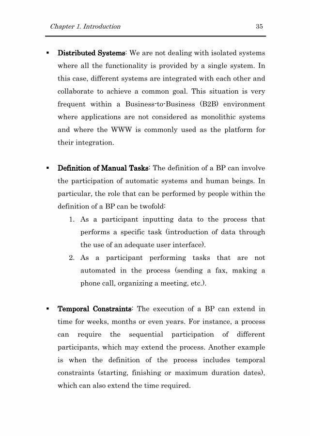
� Definition of Manual TasksDefinition of Manual TasksDefinition of Manual TasksDefinition of Manual Tasks: The definition of a BP can involve
the participation of automatic systems and human beings. In
particular, the role that can be performed by people within the
definition of a BP can be twofold:
1. As a participant inputting data to the process that
performs a specific task (introduction of data through
the use of an adequate user interface).
2. As a participant performing tasks that are not
automated in the process (sending a fax, making a
phone call, organizing a meeting, etc.).
� Temporal ConstraintsTemporal ConstraintsTemporal ConstraintsTemporal Constraints: The execution of a BP can extend in
time for weeks, months or even years. For instance, a process
can require the sequential participation of different
participants, which may extend the process. Another example
is when the definition of the process includes temporal
constraints (starting, finishing or maximum duration dates),
which can also extend the time required.

36 Chapter 1. Introduction
� Kinds of interaction between the participants of a BPKinds of interaction between the participants of a BPKinds of interaction between the participants of a BPKinds of interaction between the participants of a BP: Apart
from the human-machine and machine-machine interaction
that already exist in traditional applications, BPs can also take
into account the human-human interaction (interaction that is
commonly found in workflow applications).
In addition to considering Web engineering methods, Business
Process Management Systems (BPMS) can also be taken into
account as a solution for handling the BPs of the organization (in
particular for long-running BPs). Examples of these systems are
JBoss jBPM3, IBM WebSphere4, Oracle BPEL Process Manager5
or Biztalk6. These systems, according to the definition provided by
the Workflow Management Coalition in (WfMC, 1999) are “A
system that defines, creates and manages the execution of
workflows through the use of software, running on one or more
workflow engines, which is able to interpret the process definition,
interact with workflow participants and, where required, invoke
the use of IT tools and applications”. As this definition states,
these tools provide support to the BPM within its whole life-cycle.
This life-cycle includes five stages which are BP (1) Design, (2)
Modelling, (3) Execution, (4) Monitoring and (5) Optimization.
BPMS include different tools to perform each of these stages. For
instance, while a graphical editor allows performing the modelling
3 http://www.jboss.com/products/jbpm
4 http://www-306.ibm.com/software/websphere/
5 www.oracle.com/technology/bpel
6 http://www.microsoft.com/biztalk/

Chapter 1. Introduction 37
stage, the process execution runtime allows activating processes
and orchestrating people, data and systems that are involved in
the BP. Figure 1.1 shows the typical components that are
available in most BPMS products.
Figure 1.1 Workflow Reference Model from (Hollingsworth, 1995)
However, BPM systems are mainly focused on the process itself
(its definition, execution and efficiency) and not in other aspects
such as the user interfaces used to allow users interacting with
the process. In fact, the kind of interfaces provided by these
solutions are quite basic and little elaborated. Moreover, these
interfaces are provided at the implementation level. As a result,
any modification must be performed at this level. This approach
does not fit in a context where the software development process is
based on models. Moreover, the majority of these solutions are
commercial suits whose use and implantation forces us to use
proprietary languages and technologies, moving us away from the
standards.
38 Chapter 1. Introduction
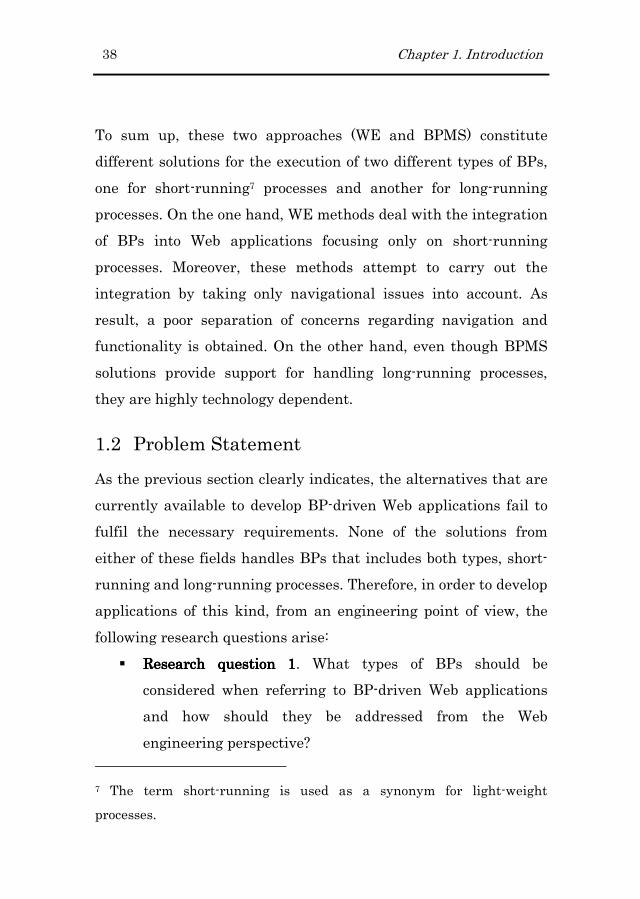
To sum up, these two approaches (WE and BPMS) constitute
different solutions for the execution of two different types of BPs,
one for short-running7 processes and another for long-running
processes. On the one hand, WE methods deal with the integration
of BPs into Web applications focusing only on short-running
processes. Moreover, these methods attempt to carry out the
integration by taking only navigational issues into account. As
result, a poor separation of concerns regarding navigation and
functionality is obtained. On the other hand, even though BPMS
solutions provide support for handling long-running processes,
they are highly technology dependent.
1.2 Problem Statement
As the previous section clearly indicates, the alternatives that are
currently available to develop BP-driven Web applications fail to
fulfil the necessary requirements. None of the solutions from
either of these fields handles BPs that includes both types, short-
running and long-running processes. Therefore, in order to develop
applications of this kind, from an engineering point of view, the
following research questions arise:
� Research question 1Research question 1Research question 1Research question 1. What types of BPs should be
considered when referring to BP-driven Web applications
and how should they be addressed from the Web
engineering perspective?
7 The term short-running is used as a synonym for light-weight
processes.

Chapter 1. Introduction 39
� Research question 2Research question 2Research question 2Research question 2. Since WE is moving towards MDE
(Vallecillo et al., 2007), what role should BP specifications
play throughout the development process?
� Research question 3Research question 3Research question 3Research question 3. How should BP specifications be
defined during the development process (i.e. which
notation/language)?
� Research question 4Research question 4Research question 4Research question 4. How can a correct separation of
concerns with regard to navigation be achieved when we
are dealing with BP integration?
These research questions are analyzed and answered in the
following section.
1.3 Main Contributions
The challenge of integrating BPs into Web applications has
already been addressed by existing Web engineering methods.
However, the proposed solutions do not perform the integration of
BPs in their broader sense. Therefore, we provide a method for the
systematic development of BP-driven Web applications for both
short-running and long-running processes. We have taken into
account the four research questions presented above in order to
define the method. These questions represent a key factor in the
successful achievement of the proposal.
First of all, regarding reseresereseresearch question 1arch question 1arch question 1arch question 1, we present a method
that allows short-running and long-running BPs to be
represented. Although BPs are similarly specified at the modelling

40 Chapter 1. Introduction
level in both cases (both are represented as BP diagrams using a
particular graphical notation), the GUIs that are generated to cope
with their execution are different for each case. This
differentiation produces a more appropriate GUI for each case.
Besides, taking into account the characteristics that BP-driven
Web applications require, the method also handles:
1. The definition of manual tasks within the BP
specifications. The particularity of activities of this kind is
that they are completely performed by human participants
and outside of the boundaries of the system.
2. The definition of BPs as a composition of activities that are
performed by different systems.
Regarding research question 2research question 2research question 2research question 2, we propose the use of BP
specifications to produce two different kinds of artefacts during
the development process. Following the MDE, a set of model
transformations (model-to-model and model-to-text) has been
defined to automate as much as possible the production of the
following artefacts as much as possible:
1. The Navigational and Presentation models required to
support BP specified in the BPM. These models
respectively capture the requirements in terms of (1) the
content and functionality necessary to allow the user to
perform process tasks and (2) the organization of these
elements within the corresponding GUI.
2. An equivalent definition of the BP in terms of an
executable language. This transformation will bring these

Chapter 1. Introduction 41
specifications to life by deploying them into a process
engine.
This set of transformations has been automated and is provided as
part of a prototype tool8. This tool has been developed in the
context of the Eclipse platform and supports the proposed method
from the modelling phase through the code generation phase, thus
automating the entire development process.
Regarding research question 3research question 3research question 3research question 3, we propose the use of standards
during the development process. Thus, we propose the use of:
1. The BPMN (OMG, 2006) notation for specifying BPs at the
modelling level.
2. The WS-BPEL (Andrews et al., 2003) language for the
execution of these BPs.
Finally, regarding research question 4research question 4research question 4research question 4, we propose to achieve the
separation of concerns related to navigation by maintaining the
navigation that occurs during BP execution inside the definition of
the process. This is possible since we have extended the
architecture of the generated Web applications by introducing a
process engine that is capable of handling the execution of BPs.
This element is necessary at the architectural level since the
navigation that occurs during BP execution (1) is more controlled9
than pure/content navigation and (2) the flow complexity found in
long-running BPs cannot be handled properly in the Navigational
8 http://oomethod.dsic.upv.es/labs/projects/bizzy
9 The process is the one driving the user to the next step

42 Chapter 1. Introduction
model. However, although we do not move BP flow into the
Navigational model, we still need to specify the set of data and
functionality that is going to be included in the Navigational
models in order to perform BP tasks. Therefore, these are the kind
of elements that are included in the Navigational model.
The solution proposed in this thesis has been applied to a method
developed within the Web Engineering area, the OOWS (Object-
Oriented Web Solution) approach (Fons, 2008). This approach has
already been extended to cope with requirements (Valderas, 2008),
adaptivity (Rojas, 2008), and Service Oriented Architectures
(Quintero, 2008). In this thesis, we propose an extension to endow
the method with enough expressivity to model Web applications
that provide support to the execution of BPs.
1.4 Research Methodology
Taking as reference the design research methodology described by
(March & Smith, 1995; Vaishnavi & Kuechler, 2004), the research
performed in this thesis has involved the following five steps: (1)
awareness of the problem, (2) suggestion, (3) development, (4)
evaluation, and (5) conclusion. These steps are graphically
depicted in Figure 1.2.
Figure 1.2 Research methodology followed in this thesis

Chapter 1. Introduction 43
First of all, according to this methodology, we identified and stated
the problem subject of this thesis. As a result, the boundaries of
the problem being considered were clearly identified.
Then, the second step in the methodology involved suggesting a
solution to the previously identified problem. The solution was
designed taking into account the research developed in the Web
Engineering area. However, in contrast to the solutions proposed
in this area, the suggested solution was also influenced by the
architecture used by Business Process Management Systems
(BPMS). Therefore, not only new abstractions for describing BP-
driven Web applications were identified, in addition, a revision of
the architecture of the generated Web applications was performed.
During the third step, the solution designed in the previous step
was developed. This development was in turn performed in several
sub steps as follows:
� First, the correspondences between the identified
abstractions and different software artifacts were designed.
These correspondences allowed us evolving the system
specification to (1) complete the specification by building
different aspects of the system and (2) generating the
equivalent representation but this time in terms of an
implementation technology.
� In parallel to the first sub step, we defined a strategy to
implement these correspondences. This decision was highly

44 Chapter 1. Introduction
influenced by the use of standards and the tool support
provided by each strategy.
� After the two previously sub steps, and by following the
previously defined strategy, these correspondences were
implemented.
As a result of the third step, a tool implementing the proposed
solution was obtained. With this tool we could validate the
proposed solution by developing different case studies. This
validation constitutes step four.
Finally, after putting in practice the proposed solution and
observing the obtained results, a set of conclusions have been
presented. In addition, new research challenges emerged to this
work are also proposed.
1.5 Thesis Development Context
This work has been developed in the OO-Method group, which
belongs to the Department of Information Systems and
Computation at the Technical University of Valencia. The OO-
Method group research interests span multiple areas that involve
Requirements Engineering, Web Engineering, Human-Computer-
Interaction, Software Quality and Ambient Intelligence, all of
which are tackled from the modelling perspective.
The work developed in this thesis started in the Web Engineering
subgroup. This group has developed a Web Engineering method
that covers the most requested requirements of current Web

Chapter 1. Introduction 45
applications. The works that have enabled the development of the
present thesis are framed in the following projects:
� “DESTINO: Desarrollo de E-Servicios para la nueva
sociedad digital”. CICYT Project referenced as TIN2004-
03534. (From 2004 to 2007).
� “WEE-NET: Web Engineering Network of Excellence“. E.U.
ALFA (América Latina – Formación Académica)
Programme.
� “SESAMO: Construcción de Servicios Software a partir de
Modelos”. CICYT Project referenced as TIN2007-62894.
(From 2008 to 2010).
1.6 Structure of the Thesis
This document has been organized in five parts as follows:
Part one. InPart one. InPart one. InPart one. Introductiontroductiontroductiontroduction
� Chapter 2. Foundations.Chapter 2. Foundations.Chapter 2. Foundations.Chapter 2. Foundations. This chapter provides the
foundations for this work, these span Web Engineering,
BP, and a combination of these two areas, BP-driven Web
applications. First, the chapter presents the basics of the
Web engineering method that has been taken as the basis
for this thesis. Second, it presents the BP notation and the
executable language used in the development of this work.
Finally, it states the characteristics that are observable in
BP-driven Web applications. Based on these characteristics
it proposes a set of requirements that Web Engineering
methods should satisfy in order to specify BP-driven Web
applications.

46 Chapter 1. Introduction
� Chapter 3. State of the Art.Chapter 3. State of the Art.Chapter 3. State of the Art.Chapter 3. State of the Art. This chapter provides an
analysis of the literature found in the Web engineering
area. In particular, this chapter focuses on the solutions
proposed by each of the reviewed methods regarding the
integration of BP.
Part two. OOWSPart two. OOWSPart two. OOWSPart two. OOWS----BP ExtensionBP ExtensionBP ExtensionBP Extension
� Chapter 4. Development ProcessChapter 4. Development ProcessChapter 4. Development ProcessChapter 4. Development Process. This chapter provides the
big picture of the proposal. It presents the set of models
that are included in the proposal, the relationships among
all of them, and the artefacts consumed and generated in
each step of the development process.
� Chapter 5. Business Process Model. Chapter 5. Business Process Model. Chapter 5. Business Process Model. Chapter 5. Business Process Model. This chapter presents
the Business Process Model that has been defined for the
specification of BP. This model is based on the BPMN
notation, we also discuss the limitations found in the
original notation and extend it for use in the context of this
work.
� Chapter 6. Navigational Extension. Chapter 6. Navigational Extension. Chapter 6. Navigational Extension. Chapter 6. Navigational Extension. This chapter presents
the navigational abstractions that have been defined to
cope with the construction of the GUIs that support BPs.
� Chapter 7. Presentation Extension.Chapter 7. Presentation Extension.Chapter 7. Presentation Extension.Chapter 7. Presentation Extension. This chapter presents
the abstractions that have been defined in the Presentation
model in order to properly specify BP-driven Web
applications. In addition, based on usability requirements,
this chapter covers the mechanisms provided by the
proposal to obtain a more usable GUI.
Chapter 1. Introduction 47
Part three. OOWSPart three. OOWSPart three. OOWSPart three. OOWS----BP FrameworkBP FrameworkBP FrameworkBP Framework
� Chapter 8. Architectural Extension.Chapter 8. Architectural Extension.Chapter 8. Architectural Extension.Chapter 8. Architectural Extension. This chapter presents
the architecture of the generated applications to provide
support for BP-driven Web applications.
� Chapter 9. Model TransformationsChapter 9. Model TransformationsChapter 9. Model TransformationsChapter 9. Model Transformations This chapter presents
the transformations that have been designed to obtain an
executable web application. These transformations cover
(1) the generation of executable BP and (2) the generation
of the proper user interface.
� Chapter 10. Tool support.Chapter 10. Tool support.Chapter 10. Tool support.Chapter 10. Tool support. This chapter presents the tool
that has been developed within the context of the Eclipse
project to support the development process of BP-driven
Web applications.
Part four. Conclusions and Further workPart four. Conclusions and Further workPart four. Conclusions and Further workPart four. Conclusions and Further work
� Chapter 11. Conclusions and Chapter 11. Conclusions and Chapter 11. Conclusions and Chapter 11. Conclusions and Further Further Further Further WorkWorkWorkWork. This chapter
summarizes the main contributions of this work and
presents future research work.
Part five. AppendixesPart five. AppendixesPart five. AppendixesPart five. Appendixes
� AppendiAppendiAppendiAppendix A.x A.x A.x A. This appendix introduces the Library4U case
study that is used throughout appendixes B and C to
illustrate how short-running and long-running processes
are modelled following the proposed approach. Moreover,
the development of these case studies allows us to validate
the proposal.

48 Chapter 1. Introduction
� Appendix B. Appendix B. Appendix B. Appendix B. This appendix extends the Library4U case
study presented in appendix A to present a short-running
BP.
� Appendix C. Appendix C. Appendix C. Appendix C. This appendix extends the Library4U case
study presented in appendix A to present a long-running
BP.

Chapter 2
2 Foundations
This chapter presents the concepts and notions in which this
thesis is based on and that are going to be used throughout this
thesis. This work is related to two areas which are Web
Engineering (WE) and Business Processes (BP). Within the WE
area, we have applied the developed work to the OOWS approach
(Fons, 2008). Therefore, in section 2.1 we present the basics of this
approach. Similarly to the WE area, within the BP area there are
several notations (BPML, BPMN, XPDL, UML Activity Diagrams)
and executable languages (WS-BPEL, XPDL) that can be used to
specify and execute processes. We have chosen the process
standards BPMN (OMG, 2006) and WS-BPEL (Andrews et al.,
2003), which deal with BP specification at different levels of
abstraction (modelling and execution respectively). Finally, in
section 2.3 we state the characteristics that differentiate the two
different types of processes covered in this thesis which correspond
to short-running and long-running BPs. Based on the stated
characteristics, we propose a set of requirements that Web
Engineering methods should satisfy in order to specify properly
what we have named BP-driven Web applications.

50 Chapter 2. Foundations
2.1 Web Engineering
To deal with the particularities that characterize Web applications
compared to traditional software (desktop applications),
researchers started working on the definition of methods for the
systematic construction of this kind of systems. These methods
were not defined from the scratch; in fact, they were based on
existing methodologies for traditional software development such
as object oriented techniques. The main contributions of these new
methods were the introduction of new abstractions to deal with
modeling navigation and presentation concerns.
In the following subsections we present the basics of the Web
Engineering method in which we have applied this thesis work,
the OOWS approach.
2.1.12.1.12.1.12.1.1 The OOWS Web Engineering MethodThe OOWS Web Engineering MethodThe OOWS Web Engineering MethodThe OOWS Web Engineering Method
OOWS (acronym standing for “Object-Oriented Web Solution”) is a
method that was conceived to provide a methodological support for
the development of Web applications applying the principles of the
Web Engineering. This method defines a set of extensions to the
OO-Method approach (Pastor et al., 2001) aimed at the
construction of object-oriented applications. In particular, this
extension introduces the User, Navigational and Presentation
Models which allows describing the requirements that define the
interaction of the user with those systems. The extension also
defines new model compilers that allow completing the code
Chapter 2. Foundations 51
generation phase by transforming these new models into their
corresponding software artefacts.
2.1.1.12.1.1.12.1.1.12.1.1.1 The OOWS User ModelThe OOWS User ModelThe OOWS User ModelThe OOWS User Model
The User Model allows identifying and categorizing users. It
allows determining the kind of users that are going to interact
with the system. These kinds are organized within a hierarchical
structure that represents the specialization/generalization
relationships between them. In addition, this model allows
characterizing users into three groups which are:
� AnonymAnonymAnonymAnonymousousousous. This kind of users does not need to be
identified in the system to access to it. Normally, they
have a very limited access to data and functionality. In
particular “sensitive”, “critical” or “personal” data is
hidden to anonymous users.
� RegisteredRegisteredRegisteredRegistered. This kind of users requires to be identified in
the system and represents users with access to data and
functionality defined as “sensitive”, “critical” or “personal”.
� Abstract (or without access)Abstract (or without access)Abstract (or without access)Abstract (or without access). This kind refers to “virtual”
types of users which are defined (1) to express the set of
common responsibilities defined for a group of users, (2) to
capture the functional hierarchy of the organization and
(3) to organize and structure the users of the system.
The graphical notation used to identify types of users according to
their access permission is presented in Figure 2.1.

52 Chapter 2. Foundations
Figure 2.1 Types of Users According to the Different Access Permission
Regarding the relationship between user types, this mechanism
allows inheriting navigational properties between them. In
addition, child user types can modify the inherited navigational
maps by adding or removing access to nodes or links. Figure 2.2
shows the User Model defined for the case study developed in
Appendix A. In it, the Librarian and Secretary types inherit the
navigational properties defined for the Member type which in turn
inherits from the Anonymous user type.
Figure 2.2 Example of User Specialization
2.1.1.22.1.1.22.1.1.22.1.1.2 The OOWS Navigational ModelThe OOWS Navigational ModelThe OOWS Navigational ModelThe OOWS Navigational Model
The Navigational model has been defined to describe the system
accessibility for the type of users defined in the User Model. This
model is built in two steps. First of all a global description of the
interaction points with users is performed. This step is called the
“Authoring-in-the-large” step. Then, a detailed description of these

Chapter 2. Foundations 53
interaction points is performed. This step is called “Authoring-in-
the-small” step.
AuthoringAuthoringAuthoringAuthoring----inininin----thethethethe----large large large large StepStepStepStep
During this step, we describe the way a particular type of user will
be able to navigate through the system for consulting some
information and performing some functionality, attending to her
responsibilities and privileges as user of the system.
Figure 2.3 Navigational Map for the Library4U Case Study
Figure 2.3 represents the Navigational map built for the
Library4U case study. This map is represented as a directed graph
whose nodes represent navigational contexts or navigational
subsystems and whose arcs represent navigational links that
define the valid navigational paths over the system. Navigational
links correspond to arcs from the navigational map and are used
to define reachability paths among different nodes. There are two
types of navigational links:

54 Chapter 2. Foundations
� Sequence links or “contextual links” (represented using
solid arrows) involve a semantic navigation between two
contexts understanding semantic navigation as the activity
of carrying some information from a source context to
target context.
� Exploration links or “non contextual links” (represented
using dashed arrows) represent valid navigation paths
through different contexts. In contrast to the navigation
defined by sequence links, this navigation does not involve
carrying information between contexts. These links are
implicitly defined by exploration contexts or exploration
subsystems.
During this stage, without specifying the details of the nodes, we
can build a system accessibility structure that allows organizing
the tasks and responsibilities of a particular kind of user.
AuthoringAuthoringAuthoringAuthoring----inininin----thethethethe----small small small small StepStepStepStep
Within this step, the navigational contexts (nodes) defined in the
navigational map built previously are detailed (see Figure 2.4).
Navigational contexts are made up of a set of Abstract Information
Units (AIU), which represent the requirement of retrieving a
chunk of related information. AIUs are made up of navigational
classes, which represent views over the classes defined in the
Class Diagram. These views are represented graphically as UML
classes that are stereotyped with the «view» keyword and that
contain the set of attributes and operations that will be available
to the user. Each AIU must include one navigational class (called
Chapter 2. Foundations 55
the manager class) and can optionally include a set of
complementary class views (called complementary classes) to
complete the information retrieved by the manager class.
Navigational classes are related by unidirectional binary
relationships called navigational relationships. These
relationships are defined over existing association or inheritance
relationships defined in the Class Diagram. Moreover, depending
on the navigational capability of the navigational relationship
these can be of two types:
1. Context Dependency Relationship (graphically represented
using dashed arrows) which represents a basic information
retrieval by crossing a structural relationship between
classes. When a Context Dependency Relationship is
defined, all the object instances related to the origin class
object are retrieved.
2. Context Relationship (graphically represented using solid
arrows) which represents the same information recovery as
a Context Dependency Relationship does plus a navigation
capability to a target navigational context, creating a
sequence link in the navigational map.

56 Chapter 2. Foundations
Figure 2.4 Navigational Context
A Service Link defines a navigation that will automatically be
performed after the execution of an operation defined within a
navigational class (navigational operation). Figure 2.4 shows an
example of a Service Link defined associated to the Book class
view. This Service Link defines the navigation to the target
context (ShoppingCart) that will be performed each time the
“addToShoppingCart()” is executed inside this context.
Apart from attributes and operations, navigational classes can
also define conditions to filter the retrieved objects. These filters
are called Population Filters and are specified by means of OCL
formulas at the bottom section of the class view primitive. In
Figure 2.4, a population filter over the Book class view has been
defined to indicate the retrieval of just those books whose
attribute “bestSeller” is set to true.

Chapter 2. Foundations 57
These are the core primitives for navigational specifications.
However, this specification can be enriched by introducing
mechanisms to help the user explore and filter the huge amount of
information inside a context. These advanced concepts are indexes
and filters. On the one hand, an index is a structure that provides
an indexed access to the population retrieved by the manager
class. Indexes create a list of summarized information by using an
attribute or a set of attributes. When an index gets activated, a
list of all the possible values for the indexed attribute/s is created.
By choosing one of these values, all objects that have the same
value for this property will be shown in a search view. This search
view describes the information that will be available to the user to
aid him/her to select an instance. This selected instance will be
activated in the navigational context. On the other hand, a filter
defines a population condition to restrict the object instances to be
retrieved. There are three types of filters which are:
� Exact filters, which take one attribute value and return all
the instances that match it exactly.
� Approximate filters, which take one attribute value and
return all the instances whose attribute values include
this value as a substring.
� Range filters, which take two values (a maximum and a
minimum) and return all the instances whose attribute
values fit within the range. If we specify only one value, it
is only bounded on that side (upper or lower bounded).

58 Chapter 2. Foundations
2.1.1.32.1.1.32.1.1.32.1.1.3 The OOWS Presentation ModelThe OOWS Presentation ModelThe OOWS Presentation ModelThe OOWS Presentation Model
The Presentation Model allows describing presentation
requirements by means of a set of basic patterns. This model is
strongly dependent on the navigational model since it uses
navigational contexts (system-user interaction units) to define the
presentation properties. Presentation requirements are specified
by means of patterns that are associated to the primitives of the
navigational context (navigational classes, navigational links,
searching mechanisms, etc.). The basic presentation patterns are:
� Information Paging. This pattern allows us to specify
information “scrolling”. All the retrieved instances are
broken down into logical blocks so that only one block is
visible at a time. Mechanisms to move forward or backward
are provided. The required information is:
o Cardinality, which represents the number of
instances that make a block.
o Access mode, which can be defined as Sequential,
providing mechanisms to go to the next, previous,
first and last logical block or Random, where the
user can directly access any block.
o Circularity. When this property is active, the set of
blocks behaves as a circular buffer.
� Ordering Criteria. This pattern defines a class population
ordering (ASCendant or DESCendant) using the value of
one or more attributes. It can be applied either to
navigational classes or access structures, specifying how
the retrieved instances will be ordered.

Chapter 2. Foundations 59
� Information Layout. We provide three basic layout patterns
and one layout operator. The three patterns are: register,
tabular (vertical and horizontal), and tree. The operator
pattern (master-detail) is applied to many-to-many
relationships using one of these basic layout patterns to
show the detail portion.
These presentation patterns, together with the specified
navigation features, capture the essential requirements for the
construction of web interfaces.
Figure 2.5 Layout Patterns applied to Navigational Class and Relationships
Figure 2.5 shows the presentation attributes associated to the
Book navigational context depicted in Figure 2.4. In particular,
the Register and Master-Detail(Text) Information layout patternS
have been associated to the classes included in the AIU.

60 Chapter 2. Foundations
In Figure 2.5, the application of the Information layout pattern to
the manager class and the navigational relationships is presented.
On the one hand, the register pattern is only applied to the
manager class. On the other hand, since a Book can have related
multiple authors, editors, subjects and copies, the tabular pattern
cannot be applied. In this case the master-detail and the text
layout pattern are combined. The master-detail pattern creates a
link between the information from the manager class (class
playing the role of master) and the complementary classes (detail).
The text layout pattern specifies that data is retrieved without
any format.
In this section we have presented the basics of the OOWS
approach which are necessary for the explanation of the presented
thesis. However, a complete description of this method is
presented in (Fons, 2008).
2.2 Business Processes
The objective of this section is to present the specifications that
are going to be used along this work to deal with the
representation of BPs. Attending to the two different levels of
abstractions defined in the proposed method (modelling and
implementation) the following two subsections present
respectively the BPMN notation (graphical notation used to
represent BPs at the modelling level) and the WS-BPEL language
(specification used to execute the BPs represented graphically at
Chapter 2. Foundations 61
the modelling level). This differentiation is necessary since WS-
BPEL, although being a powerful language, it is difficult to use
and it is not very intuitive to end-users.
2.2.12.2.12.2.12.2.1 BPMN: Business Process Modelling NotationBPMN: Business Process Modelling NotationBPMN: Business Process Modelling NotationBPMN: Business Process Modelling Notation
The BPMN standard was developed by the BPMI (Business
Process Management Initiative) mainly to provide a notation that
could be easily understood by all business stakeholders. In
addition to this goal, it was also developed to ensure that XML
languages designed for the execution of BP (such as WS-BPEL)
could be visualized with a business-oriented notation. As a result,
this notation constitutes a standardized bridge between the BP
definition and its implementation.
The common characteristics that are observable in BP design
notations are:
� Capability for modeling the sequence of activities.
� Capability for modeling the data or messages interchanged
between the participants involved in the BP definition.
� Capability for modeling different participants and different
roles within these participants.
� Capability of understanding their internal business
procedures in a graphical notation and will give
organizations the ability to communicate these procedures
in a standard manner.

62 Chapter 2. Foundations
Specifically, the BPMN notation10 provides a set of elements to
deal with the characteristics presented above. This set of elements
is organized in four categories which are Flow Objects, Connecting
Objects, Swimlanes and Artifacts:
Flow ObjectsFlow ObjectsFlow ObjectsFlow Objects
These elements constitute the main graphical elements to define
the behaviour of a Business Process. These refer to:
� Events. An event is something that “happens” during the
course of a business process. These events affect the flow of
the process and usually have a cause (trigger) or an impact
(result). Events are circles with open centre to allow
internal markers to differentiate different triggers or
results. There are three types of events, based on when
they affect the flow: Start, Intermediate, and End. Figure
2.6 shows the complete set of events defined by the
notation.
Figure 2.6 Events Graphical Elements
� Activities. An activity is a generic term for work performed
within a BP. An activity can be atomic or non-atomic
10 The BPMN version used in this work corresponds to the version 1.1

Chapter 2. Foundations 63
(compound). The types of activities that are a part of a
Business Process Diagram are: Process, Sub-Process, and
Task. Only Tasks and Sub-Processes define a specific
graphical object (a rounded rectangle). On the contrary,
Processes are built as a set of activities and the controls
that sequence them. In addition, Tasks and Sub-Processes
include a set of attributes which determine if these
activities are repeated or performed just once. This
repetition can be performed either sequentially (loop
marker) or in parallel (parallel marker). Figure 2.7 depicts
the different types of activities and the markers available
to specify when the activity can be repeated and how.
Figure 2.7 Activities Graphical Elements
� Gateways. A Gateway is used to control the divergence and
convergence of Sequence Flows. Thus, it will determine
branching, forking, merging, and joining of paths. Internal
markers will indicate the type of behaviour control. Figure
2.8 depicts the different types of gateways provided by the
notation.
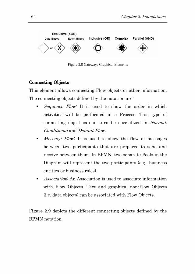
64 Chapter 2. Foundations
Figure 2.8 Gateways Graphical Elements
Connecting ObjectsConnecting ObjectsConnecting ObjectsConnecting Objects
This element allows connecting Flow objects or other information.
The connecting objects defined by the notation are:
� Sequence Flow: It is used to show the order in which
activities will be performed in a Process. This type of
connecting object can in turn be specialized in Normal,
Conditional and Default Flow.
� Message Flow: It is used to show the flow of messages
between two participants that are prepared to send and
receive between them. In BPMN, two separate Pools in the
Diagram will represent the two participants (e.g., business
entities or business roles).
� Association: An Association is used to associate information
with Flow Objects. Text and graphical non-Flow Objects
(i.e. data objects) can be associated with Flow Objects.
Figure 2.9 depicts the different connecting objects defined by the
BPMN notation.

Chapter 2. Foundations 65
Figure 2.9 Connecting Objects Graphical Elements
Swimlanes Swimlanes Swimlanes Swimlanes
This element allows grouping Flow objects based on a particular
criterion. This category includes two types of elements which are:
� Pools: represent a Participant in a Process.
� Lanes: are used to organize and categorize activities. This
is achieved by partitioning the Pool in different lanes.
Figure 2.10 depicts the different types of elements defined by the
Swimlane group.
Figure 2.10 Swimlanes Graphical Elements
Artifacts Artifacts Artifacts Artifacts
The elements included within this type are introduced into BP
models to improve their understanding. Within this category we
find:
� Data Object: This element provides information about
activity requirements and results.
� Group: The grouping can be used for documentation or
analysis purposes. Groups can also be used to identify the
activities of a distributed transaction that is shown across
Pools.

66 Chapter 2. Foundations
� Annotation: Text Annotations are the mechanism provided
to modellers to introduce additional information for the
reader of a BPMN Diagram.
Figure 2.11 Artifacts Graphical Elements
In addition to these four categories, the BPMN notation handles
advanced modelling concepts such as:
� Exception handling. By means of this mechanism we can
capture and handle exceptions during the performance of
the process. The way to capture them is by the use of
Intermediate Events (Message, Timer, and Rule) which act
like a forced end to an activity and Exception Flows.
� Transactions. These are used during the definition of Sub-
Processes. Associated to transactions we can define the
protocol that is going to be used to control the behaviour of
the Sub-process as well as the technique that will be used
to undo a transaction when this has been cancelled.
� Compensation. When the outcome of some activities result
in an undesirable situation, compensation can be specified
to undo the obtained results. To represent this scenario the
BPMN notation provides the Compensation Intermediate
Event, Association and Activity.

Chapter 2. Foundations 67
The elements presented above correspond to the version 1.0 of the
notation (OMG, 2006). This version was adopted by the OMG on
February 2006 as the official specification. However, a RFP for the
2.0 version has already been released (OMG, 2007b). The objective
of this RFP is to define a complete and consistent language based
on the BPMN and the Business Process Definition Metamodel
(BPDM) (OMG, 2007a) that unifies their capabilities (graphical
notation, metamodel and interchange format).
BPMN was not been conceived to model applications; instead, it
was conceived to model processes which will be executed within
these applications. Therefore, a BPMN model needs to be
expressed in a language that could be interpreted and executed by
the software in charge of executing them. In this context,
languages such as BPML, WS-BPEL and XPDL come into play.
From this set of languages we have opted for the standard which
is the WS-BPEL language and is presented later in the following
subsection.
2.2.22.2.22.2.22.2.2 WSWSWSWS----BPEL: BPEL: BPEL: BPEL: Business Process Executable Business Process Executable Business Process Executable Business Process Executable
Language for Web ServicesLanguage for Web ServicesLanguage for Web ServicesLanguage for Web Services
Business Process Executable Language for Web Services (WS-
BPEL) is a XML-based language that allows orchestrating
interactions between Web services in a standardized manner. This
language is based on Web services, in fact, each business process
is assumed to be implemented as a Web service. Basically, a WS-

68 Chapter 2. Foundations
BPEL process describes a flow of interactions that occur between
the process and a set of services. The basic elements of a WS-
BPEL document are activities (units of work carried out to
complete the process) and partners (elements responsible of
performing process activities). Figure 2.1 depicts this basic
elements and how this relate to each other. Moreover, it also
depicts the elements defined in a WSDL document and the
mappings defined between these elements and the basic elements
of a WS-BPEL document.
Figure 2.12 Relation between WS-BPEL Process Definition and WSDL
Moreover, other elements such as correlation, data compensation,
fault and events handlers are also defined by the language. The
set of elements defined by the WS-BPEL language are:
Partner Link TypesPartner Link TypesPartner Link TypesPartner Link Types
This element is used to characterize a conversation between two
services. In this conversation the roles played by each service is
specified as well as the port type provided by the service to receive
messages. Figure 2.13 depicts graphically the structure of this
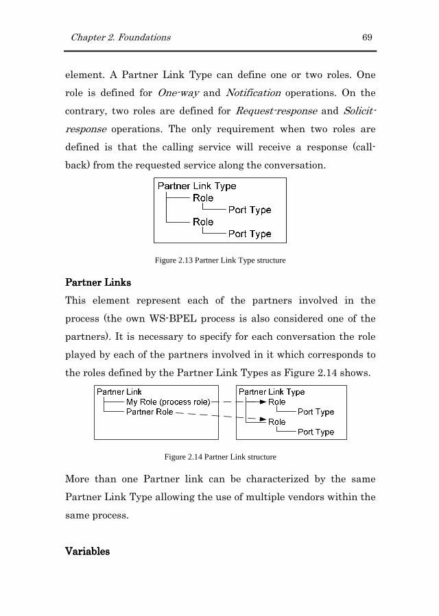
Chapter 2. Foundations 69
element. A Partner Link Type can define one or two roles. One
role is defined for One-way and Notification operations. On the
contrary, two roles are defined for Request-response and Solicit-
response operations. The only requirement when two roles are
defined is that the calling service will receive a response (call-
back) from the requested service along the conversation.
Figure 2.13 Partner Link Type structure
Partner LinksPartner LinksPartner LinksPartner Links
This element represent each of the partners involved in the
process (the own WS-BPEL process is also considered one of the
partners). It is necessary to specify for each conversation the role
played by each of the partners involved in it which corresponds to
the roles defined by the Partner Link Types as Figure 2.14 shows.
Figure 2.14 Partner Link structure
More than one Partner link can be characterized by the same
Partner Link Type allowing the use of multiple vendors within the
same process.
VariablesVariablesVariablesVariables

70 Chapter 2. Foundations
Variables are used to handle data (receive, manipulate and send
data during partner conversations) and allow maintaining the
state of the process. The types of these variables relate to data
types defined externally to the WS-BPEL process.
ActivitiesActivitiesActivitiesActivities
Activity elements describe the steps that make up a process (the
order in which these occur is defined by the flow of the process). In
WS-BPEL we can define three different types of activities which
are:
� BasicBasicBasicBasic. This type of activities are used to represent invokes
or receptions on service operations. These types are
“invoke”, “receive” and “reply”.
� StructuredStructuredStructuredStructured. This type of activities is used to specify the
order in which a set of activities can take place. Within this
group we find ordinary sequential control by the use of
“sequence”, “switch” and “while” types, concurrency and
synchronization between activities by the use of the “flow”
type and nondeterministic choice based on external events
by the use of the “pick” type.
CorrelationCorrelationCorrelationCorrelation
This is the mechanism provided by WS-BPEL to allow delivering
messages to the proper process instance. WS-BPEL addresses
correlation scenarios by providing a declarative mechanism to
specify correlated groups of operations within a service instance. A
set of correlation tokens is defined as a set of properties shared by
all messages in the correlated group.

Chapter 2. Foundations 71
All these elements are defined in the WS-BPEL version 1.1. This
version constitutes an enhanced version of the BPEL 1.0 version
and was submitted to OASIS in April 2003. As we can observe
from the elements presented above, version 1.1 of the WS-BPEL
language does not provide support for human interactions. In fact,
it is necessary to incorporate new elements to the original
specification to deal with this issue. However, the incorporation of
new elements difficult the portability of the WS-BPEL document
because this usually ties the document to the proprietary
implementation of the provider.
Related to this limitation, researchers from Active Endpoints,
Adobe, BEA, IBM, Oracle and SAP have defined two specifications
which introduce a comprehensive human interaction model for
WS-BPEL. These extensions are:
� BPEL4PeopleBPEL4PeopleBPEL4PeopleBPEL4People (Agrawal et al., 2007) which provides an
extension to BPEL to address human interactions as a
first-class BPEL citizen. It defines a new type of basic
activity which uses human tasks as an implementation,
and allows specifying tasks local to a process or use tasks
defined outside of the process definition. This extension is
based on the WS-HumanTask specification.
� WSWSWSWS----HumanTaskHumanTaskHumanTaskHumanTask (Agrawal et al., 2007a) provides the
definition of human tasks, including their properties,
behaviour and a set of operations used to manipulate
human interactions. A coordination protocol is introduced
72 Chapter 2. Foundations
to control autonomy and life cycle of service-enabled human
tasks in an interoperable manner.
In this thesis, since these two specifications did not exist, we
defined a Task Manager Service (see chapter 8) in charge of
handling the interaction with human participants.
2.3 Business Process-driven Web Applications
A Business Process-driven Web application is defined as an
application that is accessed via a Web browser over a network (i.e.,
the Internet or an intranet) and that provides support for the
execution of BP. The type of BPs that can be supported by these
applications includes different degrees of complexity, where the
complexity is given by the number and the type of interactions
defined by the BP. Based on this complexity we have catalogued
BPs into two types which are named short-running and long-
running BPs. These types are explained in detail in the following
subsections. However, before we are going to present the common
characteristics that are required in BP-driven Web applications,
independently of the type of BP supported.
� Short&Long Short&Long Short&Long Short&Long 1111. Users need mechanisms for launching BP
instances and taking up again BPs that have not been
completed.
� Short&Long 2Short&Long 2Short&Long 2Short&Long 2. Users need mechanisms for completing BP
activities. These mechanisms have to be provided according
to the type of activity been performed. For instance, when
the activity requires the introduction of data, the user has

Chapter 2. Foundations 73
to be provided with an interface that allows her inputting
this data.
� SSSShorthorthorthort&L&L&L&Long 3ong 3ong 3ong 3. Users must be guided through the steps
that allow achieving the BP goal.
� Short&Long 4Short&Long 4Short&Long 4Short&Long 4. Users can leave (suspend) the execution of
a BP for a while and taking up again (resume) the BP later
on. Therefore, the system has to keep the state of the
process to restore the BP when this is taken up again.
� Short&Long 5Short&Long 5Short&Long 5Short&Long 5. Some of the activities defined in a BP can be
performed by external system.
2.3.12.3.12.3.12.3.1 ShortShortShortShort----runningrunningrunningrunning Business PBusiness PBusiness PBusiness Processesrocessesrocessesrocesses
This type of processes is also called in the literature “light-weight
processes”. As the following list of requirements shows, its effect
has a short period of time and its consequences of a wrong decision
are small. Examples of this kind of processes are the “Check out
process” usually found in online stores or the “Booking service”
usually found in online travel agencies. These types of processes
are characterized by the following features:
� Short 1: Short 1: Short 1: Short 1: Are completed in a very short period of time
(intervals can range from seconds to a few hours).
� Short 2: Short 2: Short 2: Short 2: Involve just one human participant (who interacts
with the system/process to accomplish it) and one or more
“automated” participants.
� Short 3: Short 3: Short 3: Short 3: Are usually simple (in terms of control flow) and
not very large (big).
� Short 4: Short 4: Short 4: Short 4: Are always started by the user (human
participant).
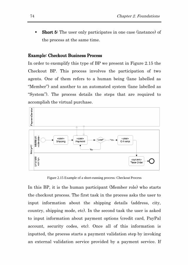
74 Chapter 2. Foundations
� Short 5: Short 5: Short 5: Short 5: The user only participates in one case (instance) of
the process at the same time.
Example: Example: Example: Example: Checkout Checkout Checkout Checkout Business ProcessBusiness ProcessBusiness ProcessBusiness Process
In order to exemplify this type of BP we present in Figure 2.15 the
Checkout BP. This process involves the participation of two
agents. One of them refers to a human being (lane labelled as
“Member”) and another to an automated system (lane labelled as
“System”). The process details the steps that are required to
accomplish the virtual purchase.
Figure 2.15 Example of a short-running process: Checkout Process
In this BP, it is the human participant (Member role) who starts
the checkout process. The first task in the process asks the user to
input information about the shipping details (address, city,
country, shipping mode, etc). In the second task the user is asked
to input information about payment options (credit card, PayPal
account, security codes, etc). Once all of this information is
inputted, the process starts a payment validation step by invoking
an external validation service provided by a payment service. If

Chapter 2. Foundations 75
the external service validates the inputted data then the user is
asked about wrapping options. Otherwise, the user is redirected to
the payment step to introduce again the payment data. Finally,
the process concludes by creating and placing the order in the
system.
Taking up again the characteristics that are observable in short-
running BP we can see that all of them are satisfied in the Check
out BP example:
� Short 1: Short 1: Short 1: Short 1: The completion of the BP only depends on the
Member user (we assume that automated activities are
completed instantaneity, i.e., the “Place order” activity
included in the System lane). Therefore, if the user does not
suspend the BP, this can be completed in a few minutes.
� Short 2: Short 2: Short 2: Short 2: The BP just includes one human participant
(represented by the Member lane) and one system
(represented by the System lane).
� Short 3: Short 3: Short 3: Short 3: The BP is quite simple and not too long, it only
includes four activities.
� Short 4: Short 4: Short 4: Short 4: The Member user (human participant) is the one
launching an instance of the BP.
� Short 5: Short 5: Short 5: Short 5: The Member user cannot participate in more than
one instances of the Checkout BP at the same time.
Figure 2.16 shows the Web interface that is provided to the
Member user to complete one of the activities defined in the Check
out BP. Specifically it shows the interface provided for
accomplishing the Shipping task where the user has to introduce

76 Chapter 2. Foundations
all the information required by the underlying operation
associated to this task (address, city, country, etc.)
Figure 2.16 Web interface to complete the first activity of the Checkout BP
2.3.22.3.22.3.22.3.2 LongLongLongLong----running Business Prunning Business Prunning Business Prunning Business Processesrocessesrocessesrocesses
These processes usually define the protocols that have to be
followed within an organization to achieve a specific goal.
Examples of this kind of processes are the “Material Purchase
Requests” or the “Incidence Management Requests”. In general,
this kind of processes involves not only the coordination of
different systems but also the coordination of different people
behaving with different roles. The following list gathers the
features/requirements observed in this kind of processes:
� LLLLong ong ong ong 1111: Usually take a long time for being completed.
There are several reasons that justify this prolongation in

Chapter 2. Foundations 77
time such as several human participants, temporal
constraints, etc.
� Long 2: Long 2: Long 2: Long 2: Usually involves more than one human participant
and one or more automated systems.
� Long 3: Long 3: Long 3: Long 3: Can include temporal constraints that provoke that
some tasks cannot be started until a specific instant of
time.
� Long 4: Long 4: Long 4: Long 4: Can be started by any participant involved in the
process. (Therefore, it is advisable that users could find
easily the set of pending tasks that she/he is responsible
of).
� Long 5: Long 5: Long 5: Long 5: The user can participate in more than one case
(instance) of the process at the same time.
Example: Book Purchase Request Business ProcessExample: Book Purchase Request Business ProcessExample: Book Purchase Request Business ProcessExample: Book Purchase Request Business Process
To exemplify this kind of processes we are going to make use of
the “Book Purchase Request” BP depicted in Figure 2.17.
Figure 2.17 Example of a long-running process: Book Purchase Request
This BP is started by a Member user who wants a specific book
that it is not catalogued in the library. Therefore, the user

78 Chapter 2. Foundations
provides in the first step the information of the specific book (i.e.,
book title or ISBN). Then, the book request is processed by any
user belonging to the Secretary User type. In this step, the user
validates the request based on some criteria. If the Secretary User
denies the purchase request, the system notifies the member
(usually by sending an e-mail). On the contrary, if the purchase
request is approved, this request is redirected to the Central
Library, which is responsible of the purchase of the requested
books. At this point the process is waiting for the purchase
notification response sent back by the Central Library. When this
notification arrives, the system must load the book details into the
Library4U system and in parallel, any user belonging to the
Secretary group has to pick up (manual operation) the book from
the Central Library. When these two tasks are completed, the
system notifies the member about the acquisition of the book and
finally one of the users belonging to the Librarian User type
finalizes the process by realizing the book loan to the solicitor
member.
Again, the characteristics found in this example map to the ones
that are observable in a long-running BP:
� LLLLong ong ong ong 1111: In this case, the existence of several human
participants propitiates the prolongation in time of the BP.
� Long 2: Long 2: Long 2: Long 2: The BP involves three human participants which
refer to users belonging to the Member, Secretary and
Librarian User types. In addition it also includes an
automated system which refers to the local system.

Chapter 2. Foundations 79
� Long 3: Long 3: Long 3: Long 3: In this case the temporal constrains are introduced
by the time that different human participants take to
complete their assigned activities.
� Long 4: Long 4: Long 4: Long 4: In this case the BP is started by a human
participant. However, compared to the Checkout BP, new
human participants are involved in the BP.
� Long 5: Long 5: Long 5: Long 5: Any of the human participants defined in the BP
can participate in different instances of the same BP. For
instance, a Secretary user has to validate each book
request launched by any member.
Figure 2.18 Web interface to complete the “Request Validation” activity of the long-running BP
Figure 2.18 shows the Web interface that is provided to the
Secretary user to complete the “request validation” task. In this
case, we can appreciate that there are two different instances of
this task.

80 Chapter 2. Foundations
2.3.32.3.32.3.32.3.3 Requirements for Dealing with BPRequirements for Dealing with BPRequirements for Dealing with BPRequirements for Dealing with BP----driven Web driven Web driven Web driven Web
applicationsapplicationsapplicationsapplications
Based on the characteristics that are observable in both types of
BPs, we enunciate the requirements that Web Engineering
methods should satisfy in order to specify and built BP-driven
Web applications. Some of these requirements have already been
stated by Damiano et al. in (Distante et al., 2007a).
� Requirement 1.Requirement 1.Requirement 1.Requirement 1. Differentiate between Short-running and
Long-running Processes. WE methods should follow a code
generation strategy that allows generating appropriate GUI
depending on the type of process being executed. For instance,
long-running processes are better handled from a Web
interface similar to the ones provided by Business Process
Management solutions. This type of Web interfaces allows
users to launch new process instances and complete their
pending tasks. On the contrary, short-running processes are
better handled from a Web interface designed following the
wizard pattern.
� Requirement Requirement Requirement Requirement 2222.... Specify the data and functionality to support
BP activities. WE methods should provide mechanisms that
allow specifying which data and functionality has to be
provided in order to complete a BP activity.
� Requirement 3Requirement 3Requirement 3Requirement 3.... Deal with the Specification of BP flows. WE
methods should provide mechanisms that allow describing the
different paths that BP can take during the execution.
� Requirement Requirement Requirement Requirement 4444.... Deal with Distributed Processes. WE methods
should provide mechanisms that allow specifying the different

Chapter 2. Foundations 81
systems involved in the process and also how these interact to
accomplish the BP goal.
� Requirement Requirement Requirement Requirement 5555.... Deal with Multiple roles. Within a single
organization, process activities are distributed among different
responsibilities. Therefore, it is necessary to provide
mechanisms for specifying the different roles involved in a BP
and how these cooperate to achieve a common goal.
� Requirement Requirement Requirement Requirement 6666.... Deal with Manual Tasks. Manual tasks are
commonly found in processes involving human participation.
Thus, it is necessary to provide mechanisms that allow
specifying tasks of this kind.
� Requirement Requirement Requirement Requirement 7777.... Separation of Concerns related to Navigation.
In terms of model reusability and maintenance, it is very
important to follow a strategy that allows a proper separation
of concerns regarding navigation. This separation should
clearly distinguish between the navigation that occurs during
the execution of a BP and the navigation that occurs during
content navigation.
� Requirement 8.Requirement 8.Requirement 8.Requirement 8. Keep the State of the BP. To ensure that users
can suspend safely the current executed BP and resuming it
correctly later, it is necessary to keep the state of the launched
BP instances.
Table 2-1 summarizes the BP characteristics that are covered by
each of the requirements stated previously.
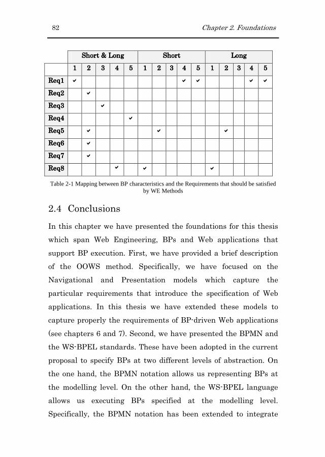
82 Chapter 2. Foundations
Short & LongShort & LongShort & LongShort & Long ShortShortShortShort LongLongLongLong
1111 2222 3333 4444 5555 1111 2222 3333 4444 5555 1111 2222 3333 4444 5555
Req1Req1Req1Req1 � � � � �
Req2Req2Req2Req2 �
Req3Req3Req3Req3 �
Req4Req4Req4Req4 �
Req5Req5Req5Req5 � � �
Req6Req6Req6Req6 �
Req7Req7Req7Req7 �
Req8Req8Req8Req8 � � �
Table 2-1 Mapping between BP characteristics and the Requirements that should be satisfied by WE Methods
2.4 Conclusions
In this chapter we have presented the foundations for this thesis
which span Web Engineering, BPs and Web applications that
support BP execution. First, we have provided a brief description
of the OOWS method. Specifically, we have focused on the
Navigational and Presentation models which capture the
particular requirements that introduce the specification of Web
applications. In this thesis we have extended these models to
capture properly the requirements of BP-driven Web applications
(see chapters 6 and 7). Second, we have presented the BPMN and
the WS-BPEL standards. These have been adopted in the current
proposal to specify BPs at two different levels of abstraction. On
the one hand, the BPMN notation allows us representing BPs at
the modelling level. On the other hand, the WS-BPEL language
allows us executing BPs specified at the modelling level.
Specifically, the BPMN notation has been extended to integrate

Chapter 2. Foundations 83
BP specifications within the method and to allow an automatic
generation of BPs represented in WS-BPEL (see chapter 5).
Finally, we have presented the kind of BPs that we are
considering in this thesis. By means of two examples we have
stated the characteristics of each type. These characteristics have
been used to define a set of requirements that Web Engineering
methods should satisfy in order to specify properly BP-driven Web
applications.

Chapter 3
3 State of the Art
This chapter provides an analysis of the most well-known methods
developed within the Web Engineering field. Specifically, this
analysis is focused on the solution provided by these methods to
deal with the integration of BPs into Web applications. First of all,
it presents the concrete solution designed by each method. This
presentation includes the mechanisms provided at the modelling
level, the adaptation of the development process to this new
feature and, when applicable, the support provided by a tool.
Then, it provides a discussion of the adequacy of the proposed
solutions to deal with the construction of BP-driven Web
applications. This discussion is based on the requirements that
Web engineering methods should satisfy to specify BP-driven Web
applications.
3.1 Web Engineering Area
In order to deal with the systematization of the Web application
development (Pressman et al., 1998), during the late nineties, a
new Engineering discipline emerged, it was called Web
Engineering (WE). This term was coined in (Murugesan et al.,

86 Chapter 3. State of the Art
1999) and was defined as “an engineering that uses scientific,
engineering, and management principles and systematic
approaches to successfully develop, deploy, and maintain high-
quality Web systems and applications”. Later, different authors
(Ginige et al., 2001a; Kappel et al., 2006; Mendes, 2006) have
supported the necessity of this new engineering to deal with the
particularities introduced by Web-based systems. As a result of
the studies developed in this area, a set of methods, models and
techniques were defined to cover, to a great extent, part of the
development cycle of Web applications.
The methods developed within the context of the WE area
emerged to provide support for the modelling of Web information
systems. The original requirements for this sort of systems were
storing, retrieving, transforming and presenting data to users.
However, Web application requirements change over time and
require more powerful and expressive methods for the
development of systems that are not simply based on data but also
in business processes (BP). Therefore, to provide support to these
necessities, the methods for the development of Web applications
have been extended and updated to provide the required
mechanisms for the modelling of this kind of systems.
The set of methods considered in this analysis constitute the most
relevant approaches within the WE area. These are UWAT+
(Distante, 2004), WebML (Ceri et al., 2000), OOHDM (Schwabe
and Rossi, 1998), UWE (Koch, 2001), OO-H (Gomez et al., 2000),
WSDM (Troyer and Leune, 1998), HERA (Houben, 2000) and
Chapter 3. State of the Art 87
MIDAS (Marcos et al., 2004). In particular, this analysis is focused
on the solutions that each of these proposals provide to perform
the construction of Web applications supporting BPs. This section
has been organized as follows. First of all it presents each proposal
by detailing the following points:
� Method descriptionMethod descriptionMethod descriptionMethod description. This point provides a general
description of each method that includes its origins,
evolution and tool support.
� Adaptation Adaptation Adaptation Adaptation to build BPto build BPto build BPto build BP----driven Web applicationsdriven Web applicationsdriven Web applicationsdriven Web applications. This
point presents the mechanisms defined by each method to
carry out the construction of Web applications providing
support to BPs.
� Development processDevelopment processDevelopment processDevelopment process. This point presents how each
proposal has modified its development process to cope with
the modelling phase related to BP.
Finally, once each proposal has been presented, section 3.1.9
provides a discussion about the support provided by the reviewed
methods to deal with the requirements introduced by BP-driven
Web applications (these requirements are detailed in section 2.3.3
from chapter 2).
3.1.13.1.13.1.13.1.1 UWAT+UWAT+UWAT+UWAT+
The Ubiquitous Web applications (UWA) framework (UWA
Consortium, 2002) is the result of a joint effort developed by a
group of researchers from different countries which constituted
the UWA Consortium (www.uwaproject.org). As its name stands
for, this framework provides a methodology for the construction of
88 Chapter 3. State of the Art
ubiquitous Web applications. The ubiquitous aspect provides
flexibility regarding the target device and the usage context in
which Web applications are going to be used.
The objective of the UWA project was the production of an
environment that would allow covering the development process of
ubiquitous Web applications from requirements to the design
phase. This consortium proposes the use of an extended and
customized UML notation along the development process.
The aspects considered by the consortium for the definition of the
framework include “Requirements Elicitation: Model, Notation
and Tool Architecture”, “Hypermedia and Operation design: model
and tool architecture”, “Transaction design” or “Customization
design”.
Authors in (Distante et al., 2007) state that UWA provides a set of
tools for describing ubiquitous Web applications. However we have
not found any tool or even document where these tools were
presented or explained.
3.1.1.13.1.1.13.1.1.13.1.1.1 Adaptation to integrate processAdaptation to integrate processAdaptation to integrate processAdaptation to integrate process----driven Web driven Web driven Web driven Web
applicationsapplicationsapplicationsapplications
Originally, the UWA framework did not face properly aspects such
as (1) the necessity of describing the scenarios where process
execution and navigation are mixed, (2) the specification of the set
of contents and objects related to a particular activity or (3) the

Chapter 3. State of the Art 89
design of the collaboration of different users within a BP.
Therefore, to deal with these limitations an extension called
UWAT+ was proposed by (Distante, 2004). This extension focuses
on the Transaction and Navigation Design phases of the
development process.
On the one hand, the Organization and Execution Models built
during the Transaction Design phase have been extended as
follows:
� The Organization Model represents a web transaction from
a static point of view. The main change introduced in this
model allows differentiating the kind of relationships
between activities. On the one hand, Hierarchical Relations
allow specifying whether a sub-activity is required or
optional to complete the associated activity. On the other
hand, Semantic Relations allow specifying the dependence
between two activities.
� The Execution Model represents a web transaction from a
dynamic point of view. The main change introduced to the
original model is that system activities are specified
separately from user related aspects.
On the other hand, new diagrams have been included in the
Navigational Model built during the Navigation Design phase.
These diagrams are used as follows:
� The Activity Node concept was introduced to represent an
elementary activity of a BP. This node is an interactive
unit of information provided to the user in a single step.

90 Chapter 3. State of the Art
� The Activity Cluster concept specifies the possible
navigation between a set of nodes. This navigation includes
the interaction between process execution and content
navigation.
In addition, the state of the process and its activities is kept in the
system by means of a set of variables.
3.1.1.23.1.1.23.1.1.23.1.1.2 Development ProcessDevelopment ProcessDevelopment ProcessDevelopment Process
UWA defines six models to carry out the specification of Web
applications. First, following a goal-oriented approach,
requirements are gathered in the (1) RequirementsRequirementsRequirementsRequirements ModelModelModelModel. Second,
(2) ConceptualConceptualConceptualConceptual Model Model Model Model is built to specify the content of the
application as well as the ways to access to it. In addition, with
regard to the high-level transactional goals gathered in the
requirements model, static and dynamic views of these
requirements are defined in the (3) OrganizationOrganizationOrganizationOrganization and (4)
ExecutionExecutionExecutionExecution models respectively. These two models have been
extended to deal with the specification of BPs (see section 3.1.1.1).
Then, (5) the NavigationNavigationNavigationNavigationalalalal model model model model is built to define the navigation
throughout the content (Conceptual model) of the application. New
diagrams have been included in this model to deal with the
specification of BPs. Finally, the pages of the final Web application
are designed in the (6) Publishing modelPublishing modelPublishing modelPublishing model.
The development process is made up of six phases which produce
each of the models presented above. Figure 3.1 shows the
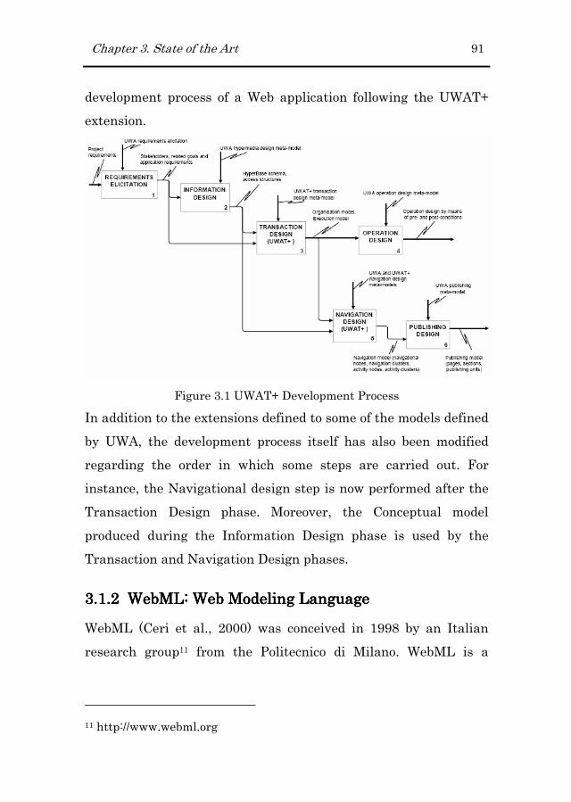
Chapter 3. State of the Art 91
development process of a Web application following the UWAT+
extension.
Figure 3.1 UWAT+ Development Process
In addition to the extensions defined to some of the models defined
by UWA, the development process itself has also been modified
regarding the order in which some steps are carried out. For
instance, the Navigational design step is now performed after the
Transaction Design phase. Moreover, the Conceptual model
produced during the Information Design phase is used by the
Transaction and Navigation Design phases.
3.1.23.1.23.1.23.1.2 WebML: Web Modeling LanguageWebML: Web Modeling LanguageWebML: Web Modeling LanguageWebML: Web Modeling Language
WebML (Ceri et al., 2000) was conceived in 1998 by an Italian
research group11 from the Politecnico di Milano. WebML is a
11 http://www.webml.org
92 Chapter 3. State of the Art
notation for specifying complex Web sites at the conceptual level
avoiding designers to commit detailed architectural details.
Originally, WebML was conceived to support the design and
implementation of data-intensive Web applications; however, as a
response to the new arising challenges appeared in the Web,
WebML has evolved continuously to satisfy some of these new
challenges. As a result of this evolution, WebML has been
extended to address the generation of: web service-enabled
(Brambilla et al., 2006b), workflow-based (Brambilla et al., 2006),
context-aware (Ceri et al., 2007), semantic web (Brambilla et al.,
2006a) and rich internet (Bozzon et al., 2006) applications. A
complete description of this method gathering all these extensions
is presented in (Brambilla et al., 2008).
Moreover, the WebML modelling language and its development
method are implemented in a commercial Web tool called
WebRatio Site Development Studio12. This tool covers the
development process and automates the generation of the
relational database and the application page templates. This tool
allows fast-prototyping and can be also used for implementation,
maintenance and evolution of the modelled Web applications.
12 http://www.webratio.com

Chapter 3. State of the Art 93
3.1.2.13.1.2.13.1.2.13.1.2.1 Adaptation to integrate processAdaptation to integrate processAdaptation to integrate processAdaptation to integrate process----driven Web driven Web driven Web driven Web
applicationsapplicationsapplicationsapplications
Web sites are described in WebML by means of four distinct
orthogonal models which are (1) the structural modelstructural modelstructural modelstructural model (which
defines the data content by means of a compatible language with
classical notations like the E-R model and the UML class
diagrams), (2) the hypertext modelhypertext modelhypertext modelhypertext model which in turn consists of two
submodels, the composition modelcomposition modelcomposition modelcomposition model (which defines the pages that
compose the site) and the navigation modelnavigation modelnavigation modelnavigation model (which defines the
topology of links between pages), (3) the presentation modelpresentation modelpresentation modelpresentation model
(which defines the layout and graphic requirements for page
rendering and (4) the personalization modelpersonalization modelpersonalization modelpersonalization model (which defines the
customization features for one-to-one content delivery).
However, none of the previously four presented original models
were aimed at the development of workflow-based applications.
Then, in order to deal with this limitation, WebML was extended
to provide support to lightweight Web-enabled workflows
(Brambilla, 2003; Brambilla et al., 2003; Brambilla et al., 2006).
The proposed extension embraces both the language and the
methodology itself. On the one hand, the language extension
includes:
� The introduction of a new dimension (the BP model) into
the methodology to deal with BP modeling. The notation
used to deal with the BP modeling is the BPMN notation.
� The extension of the data model (see Figure 3.2) with a set
of objects to describe the meta-data that is necessary for

94 Chapter 3. State of the Art
tracking the execution of the BP. This extension
represents a reference model that gathers the process
relevant information that is outside the data application.
Figure 3.2 Data Model Extended
� The extension of the hypertext model to specify business
activity boundaries and the workflow-dependent
navigation links.
On the other hand, the extension regarding the methodology
involves the following changes:
� New phases were introduced into the development process
to cope with the modelling of BPs and their integration
with the conceptual models.
� The design tool has been extended to allow the design of
workflow models.
� New transformations for translating workflow diagrams
into skeletons of Web applications defined in the WebML
language.

Chapter 3. State of the Art 95
3.1.2.23.1.2.23.1.2.23.1.2.2 Development ProcessDevelopment ProcessDevelopment ProcessDevelopment Process
WebML proposes an iterative and incremental development
process (see Figure 3.3) where various tasks are repeated and
refined until results meet the business requirements. This model
allows the continuous testing, evaluation, modification or
extension of each version of the system. As Figure 3.3 shows, the
conceptual design phase has been extended with two new tasks
(the process design and the process distribution) to endow the
method for the generation of process-aware Web applications.
Figure 3.3 WebML Extended Development Process
� The process designprocess designprocess designprocess design task is focused on the high-level
schematization of the processes underlying the application.
Although the process design task is performed at the
beginning of the conceptual design phase, this is not
strictly immovable. If data is the central role of the
application, the design task can be postponed after the data
design task to fit better the application requirements
nature.
� The process distributionprocess distributionprocess distributionprocess distribution task is focused on addressing the
allocation of sub-processes to different peers, and therefore
96 Chapter 3. State of the Art
occurs only when there are several Web servers involved in
the process enactment.
These two phases have influence over the data and hypertext
design phases. This influence is clearly seen by the extensions
performed to each of these models.
3.1.33.1.33.1.33.1.3 OOHDM: ObjectOOHDM: ObjectOOHDM: ObjectOOHDM: Object----Oriented Hypermedia Design Oriented Hypermedia Design Oriented Hypermedia Design Oriented Hypermedia Design
MethodMethodMethodMethod
The OOHDM proposal was developed by Schwabe and Rossi in
1994 (Schwabe & Rossi, 1998).
The set of models proposed by the OOHDM approach is based on
object-oriented concepts, using concepts such as object structure
and behaviour and abstraction mechanisms such as aggregation
and generalization/specialization. However, although this method
is based on object-oriented concepts, the resulting design can be
implemented on top of any conventional platform.
The OOHDM method has evolved since its conception and it has
been adapted to deal with the demanding necessities of each
moment. Then, we find extensions to deal with Semantic Web
technologies (Lima & Schwabe, 2003; Schwabe et al., 2004),
adaptation (de Assis et al., 2006), BPs (Schmid & Rossi, 2004) and
rich applications (Fialho & Schwabe, 2007). A complete description
of this method gathering all these extensions is presented in
(Rossi & Schwabe, 2008).

Chapter 3. State of the Art 97
The only available tool related to OOHDM is HyperDE13.
However, this tool is based on the Semantic Hypermedia Design
Method (SHDM) method, which defines an extension to the
original method for the construction of semantic web applications.
3.1.3.13.1.3.13.1.3.13.1.3.1 Adaptation to integrate processAdaptation to integrate processAdaptation to integrate processAdaptation to integrate process----driven Web driven Web driven Web driven Web
applicationsapplicationsapplicationsapplications
The OOHDM method uses four models to specify hypermedia web
applications. (1) The ususususe case diagramse case diagramse case diagramse case diagrams are used to provide a
concise graphical representation of the interaction between the
user and the system during the execution of a task. (2) The
conceptual modelconceptual modelconceptual modelconceptual model represents the application domain. This model is
based on well-known object-oriented modeling principles. (3) The
navigational modelnavigational modelnavigational modelnavigational model describes the navigational structure of a
hypermedia application. Expressing different views on the same
domain is achieved by building different navigational models for
the same conceptual schema. (4) Finally, the abstract interface abstract interface abstract interface abstract interface
modelmodelmodelmodel is built to map navigation with perceptible objects. It
describes the interface for navigational objects and the responses
to external events.
However, all these models were conceived basically to retrieve and
manipulate the data of the system. Therefore, to deal with the
modeling of BPs, OOHDM proposes to modify its conceptual and
navigational model by bringing processes as first class citizens.
13 http://www.tecweb.inf.puc-rio.br:8000/hyperde

98 Chapter 3. State of the Art
This is achieved by adding concepts related to BPs in both models.
On the one hand, the conceptual model is extended with a new
primitive called activity (primitive abstracting the process activity
concept). As a result, the conceptual model is made up of two types
of classes, one referring to entities and another to processes. On
the other hand, the Navigational model is extended consequently
with a set of primitives related to processes. One of them is the
called activity node, primitive that describes, in an abstract way,
the visible attributes, anchors and operations, elements that will
allow the user interacting with the system during process
execution. Moreover, as activity nodes exist within the context of a
particular process, these are contained within the corresponding
process node (primitive that gathers related activity nodes).
Finally, new types of links have been added to connect different
activity nodes (navigation that does not leave the process) and
activity and entity nodes (navigation that connects pure
navigation with navigation during process execution). The
semantics of navigation changes during the execution of a process
(Schmid & Herfort, 2004), and the new links are:
� StartStartStartStart: It allows the user moving from pure navigation to
the execution of a process.
� SuspendSuspendSuspendSuspend: It allows the user leaving the execution of a
process temporally. At this point, the process state is kept
until it is taken again by the user.
� ResumeResumeResumeResume: It allows the user taking up again the process
execution from pure navigation.

Chapter 3. State of the Art 99
� TerminateTerminateTerminateTerminate: It allows the user leaving the process and
changing to pure navigation. This stage is achieved because
the process has been cancelled or finished.
Moreover, to specify the flow control of the processes, the proposal
includes a new model into the method. This model uses the UML
activity diagram notation (OMG, 2004) to specify processes.
3.1.3.23.1.3.23.1.3.23.1.3.2 Development processDevelopment processDevelopment processDevelopment process
OOHDM divides the development process into four steps which
correspond to (1) domain design, (2) navigational design, (3)
abstract interface and (4) implementation. During the first step a
conceptual domain model is described using an object-oriented
hypermedia design model. In this model primitive such as classes,
relationships and sub-systems are used. In addition, a UML
Activity Diagram has been added at this stage to define the
control flow within processes. In the second step, the hypermedia
of the application is described by means of navigational structures
which are built based on the responsibilities assigned to different
types of users. This model is partitioned in two sections which
relate to pure navigation and process execution. Then, during the
Abstract Interface Design step the specification about how users
will perceive navigational objects through the interface is
performed. Finally, during the Implementation step navigational
and abstract interface models are transformed into a concrete
implementation environment.

100 Chapter 3. State of the Art
3.1.43.1.43.1.43.1.4 UWE: UML basedUWE: UML basedUWE: UML basedUWE: UML based----web Engineeringweb Engineeringweb Engineeringweb Engineering
UWE (Koch, 2001; Koch & Kraus, 2002) came up by 1998. The
method was developed by the WE Group from the Ludwig-
Maximilians-Universität München.
It is a software engineering approach based on UML (OMG, 2004)
(it uses the UML standard notation as much as possible) and
defines a UML profile to specify the peculiarities that introduce
web applications. The major benefit of being UML compliance is
that any CASE tool that supports the UML notation can be used
to produce the UWE models.
The UWE approach has evolved to deal with new features such as
personalization or support for BP execution (Koch et al., 2004;
Knapp et al., 2004). In addition, the approach has also evolved
regarding technological issues such as adopting aspect-oriented
techniques or model driven principles (Koch, 2006; Kraus et al.,
2007; Koch, 2007). (Koch et al., 2008) provides a complete
description of the approach including all these extensions.
An extension to the open-source CASE tool ArgoUML14 has been
implemented to provide modelling support for UWE (the
development process is not realized within the tool). This tool is
called ArgoUWE15 and supports the UWE method during the
14 http://argouml.tigris.org/
15 http://www.pst.informatik.uni-muenchen.de/projekte/argouwe

Chapter 3. State of the Art 101
modelling phase. However, the code generation phase in which the
Web application is built is out of the scope of this tool.
3.1.4.13.1.4.13.1.4.13.1.4.1 Adaptation to integrate processAdaptation to integrate processAdaptation to integrate processAdaptation to integrate process----driven Web driven Web driven Web driven Web
applicationsapplicationsapplicationsapplications
UWE proposes to deal with the process of modelling web
applications with a set of models to specify four different aspects.
(1) Initially, to deal with requirements, UWE proposes the use of
Use CasesUse CasesUse CasesUse Cases and UWE Activity DiagramsUWE Activity DiagramsUWE Activity DiagramsUWE Activity Diagrams. The former is used to
specify users of the web system and the functionality that the
system will provide to them. The latter is used to provide a more
detailed description (pre and post conditions, a workflow
description, exceptions, etc.) of the functionalities specified
previously. (2) The content modelcontent modelcontent modelcontent model provides a visual specification of
the domain application. In addition, to deal with customization
aspects (adaptation to the properties of users or user groups to
features of the environment) this model is accompanied with the
user or context modelcontext modelcontext modelcontext model. Both models are graphically represented by
a UML class diagram. (3) The navigational structurenavigational structurenavigational structurenavigational structure allows
defining the navigation nodes and links, menus, access primitives
(indexes and guided tours), etc.
The extension defined by UWE involves the phases related with
requirements and the navigational structure. Moreover, it
proposes introducing a new model that allows defining the
structural and behavioural view of the process. This model is
called Process flow modelProcess flow modelProcess flow modelProcess flow model and allows modelling processes

102 Chapter 3. State of the Art
independently of navigation, achieving the always wanted
separation of concerns in the design of Web applications. An
important difference between this model and the navigational one
is that in this case, the model can include elements that are not
derived from the conceptual model.
At the requirements stage, UWE extends the Use case modelling
technique by differentiating two types of use cases, the Navigation
Use cases and the Process Use cases.
� Navigation Use casesNavigation Use casesNavigation Use casesNavigation Use cases are used to model typical user
behaviour when interacting with a web application
(browsing or searching some content).
� Process Process Process Process UUUUse casesse casesse casesse cases are used to describe business tasks that
end users will perform with the system.
On the other hand, UWE proposes enriching the navigation
structure to reflect the set of integration points where the user
leaves pure navigation to change into the view referred to process
execution. To achieve this goal, the proposal has been extended
with the inclusion of two new stereotypes, which are the Process
Class and the Process Link primitives.
� Process CProcess CProcess CProcess Classlasslasslass: This stereotype represents classes whose
instances are used by the user during the execution of a
process. It is possible to define a mapping function between
process classes and use cases (those related to processes)
similarly to the mapping functions defined between
navigational classes and conceptual classes.
� Process LProcess LProcess LProcess Linksinksinksinks: This stereotype represents the association
between a navigational class and a process class. Moreover,
Chapter 3. State of the Art 103
this kind of links needs to have associated information
about the state of the process (i.e. links must be restricted
by an OCL expression about the state of the process). This
allows taking up again activities within a process under
certain conditions.
3.1.4.23.1.4.23.1.4.23.1.4.2 Development processDevelopment processDevelopment processDevelopment process
The construction of the navigational model is performed in two
steps. The former consists in building the navigational model that
includes both navigational and process classes which have been
derived from the Use cases built in the analysis stage. The later
step consists in the introduction into the navigational model of a
set of access structures which are needed to complete the
navigation. This step is partially automated and consists in the
introduction of indexes, tourist guides and queries following
certain rules. The process structural model similar to the
navigational model is derived from the conceptual model. The
developer must determine the set of conceptual classes that are
relevant to the process flow. The Process flow model is a
refinement of the process model defined during the analysis level
and represented by means of UML activity diagrams. UWE
describes by means of this model the process behaviour (sequence
of activities that make up the process). Each activity from the
Process Flow Model defines either a UML subactivity representing
the execution of a non atomic sequence of steps or a UML call
representing an atomic action that invokes to just one operation.
This operation is always referred to operations defined in the
process classes included in the structural process model. UWE, in
104 Chapter 3. State of the Art
line with its philosophy of being UML compliance, follows strictly
the notation and semantics defined by the UML activity diagram.
3.1.53.1.53.1.53.1.5 OOOOOOOO----H: ObjectH: ObjectH: ObjectH: Object----Oriented Hypermedia MethodOriented Hypermedia MethodOriented Hypermedia MethodOriented Hypermedia Method
OO-H is an initiative started in 2000 by Gómez et al. (Gómez et
al., 2000; Cachero & Gómez, 2002). OO-H was originally defined
as an approximation addressed by the user requirements, object
oriented-based and partially based on the standards. Based on the
object-oriented paradigm, this approach provides designers with
the semantics and notation necessary for the development of
personalized Web-based interfaces.
The OO-H proposal has been extended to deal with (1) dynamic
personalization (Garrigos et al., 2003) studying how
personalization properties influence navigation and presentation
models and (2) BPs integration (Koch et al., 2004).
The analysis and design steps proposed by OO-H are supported by
a modelling environment called VisualWADE16. This tool provides
a set of model compilers that allow generating a running
application for different platforms and languages.
3.1.5.13.1.5.13.1.5.13.1.5.1 Adaptation to integrate processAdaptation to integrate processAdaptation to integrate processAdaptation to integrate process----driven Web driven Web driven Web driven Web
applicationsapplicationsapplicationsapplications
OO-H proposes to deal with the modelling process with three
different models. These models are (1) the conceptual model, (2)
16 http://www.visualwade.com
Chapter 3. State of the Art 105
the Navigational model and (3) the Presentation model. The
conceptual model is defined by means of a UML class diagram
that keeps information related to the domain object. The
Navigational model is defined by means of the Navigational
Access Diagram (NAD) which allows defining menus, navigation,
views over conceptual classes and the paths provided to the user
to traverse the system. Finally, the Presentation model is used to
define the characteristics of each navigation path. These
characteristics allow changing certain visibility features such as
different link colours.
OO-H proposes the complementary use of UML activity diagrams
to represent the process control flow, endowing the expressive
power of the OO-H to allow the modeling not uni-granular
(atomic) and multi-granular (compound) services. The integration
is performed by preserving the navigational model and ensuring
the accomplishment of the restriction imposed by the control flow
of processes. Therefore, OO-H proposes mapping the elements
defined in the process model with elements from the navigational
model.
3.1.5.23.1.5.23.1.5.23.1.5.2 Development processDevelopment processDevelopment processDevelopment process
OO-H proposes five steps for the development of web applications
that support BPs. (1) Initially, the developer must refine the
conceptual model by adding properties and even new elements to
the UML class diagram. (2) Then, the developer must refine the
process model defined at the analysis level by means of Use cases.
Taking in mind the previously refined conceptual model, it is
106 Chapter 3. State of the Art
possible to build a more detailed activity diagram where the links
between the constructs of the process design and the conceptual
model is established by the identification of UML call states
(atomic actions that would invoke the execution of only one
operation). (3) The designer must then apply a set of predefined
mapping rules that allow the automatic generation of Navigation
Access Diagrams (NAD) based on the design of process models.
This automatic generation ensures the traceability between both
models (navigational and process models). (4) Then, the designer
must perform again over the recently obtain NAD diagram the
necessary refinements such as the addition of filters or extra
navigational paths. (5) Finally, once the navigational model is
completed, the designer can continue the process by defining
presentation aspects of the system.
3.1.63.1.63.1.63.1.6 WSDM: Web Site Design MethodWSDM: Web Site Design MethodWSDM: Web Site Design MethodWSDM: Web Site Design Method
WSDM is an initiative developed in the Vrije Universiteit Brussel
(Troyer & Leune, 1998). WSDM is a methodology and as such, it
provides modelling primitives and a systematic way to develop
web sites/applications.
Originally, the WSDM abbreviation referenced a method for the
design of Web sites (Web Site Design Method). However, the
method has evolved allowing now not only the design of traditional
web applications but also the development of semantic web
applications. For this reason, the abbreviation now stands for Web
Semantics Design Method.

Chapter 3. State of the Art 107
WSDM has been extended to deal with new modelling
requirements. The most important extensions performed to the
approach are to support (1) localization (Troyer & Casteleyn, 2004)
and adaptation (Casteleyn, 2005). A complete description of this
method gathering all these extensions is presented in (Troyer et
al., 2008).
WSDM does not have any tool that provides support either to the
method or to the models defined to deal with the description of
web applications.
3.1.6.13.1.6.13.1.6.13.1.6.1 Adaptation to integrate processAdaptation to integrate processAdaptation to integrate processAdaptation to integrate process----driven Web driven Web driven Web driven Web
applicationsapplicationsapplicationsapplications
The extension proposed by WSDM involves mainly the Conceptual Conceptual Conceptual Conceptual
designdesigndesigndesign phase which in turn is constituted by the Task Task Task Task and and and and
Information MInformation MInformation MInformation Modellingodellingodellingodelling and the Navigational designNavigational designNavigational designNavigational design phases.
On the one hand, the Task ModellingTask ModellingTask ModellingTask Modelling phase endows the method to
model explicitly tasks. To deal with the modelling of tasks WSDM
uses the ConcurTaskTree (CTT) notation (Paternò et al., 1997).
This notation was developed in the context of the Human-
Computer Interaction (HCI) to describe user tasks. This notation
allows specifying four different types of tasks (user, application,
interaction and abstract tasks) as well as the temporal
relationships between these. However, WSDM does not follow
completely the original CTT notation. In fact, it has been adapted
and slightly modified (user tasks are discarded because these are

108 Chapter 3. State of the Art
considered not useful during the design stage and some operators
have modified their meaning to express temporal relationships
between tasks) to satisfy the particularities that introduced the
design of Web applications.
On the other hand, the navigational model allows now a better
separation of concerns between the structure and the process
workflow. In this case, the task navigational modeltask navigational modeltask navigational modeltask navigational model allows
describing the way in which users can perform tasks in the web
site. This model is built from the model taskmodel taskmodel taskmodel task and the object chunobject chunobject chunobject chunksksksks
defined during the previous stage of task modelling. ComponentsComponentsComponentsComponents
and Project logic linksProject logic linksProject logic linksProject logic links are used to build the task navigational
model for each task model defined previously. However, to express
the workflow or the process logic defined in the task model by
means of temporal relationships in the CTT they use what they
call Process logic linksProcess logic linksProcess logic linksProcess logic links.
3.1.6.23.1.6.23.1.6.23.1.6.2 Development processDevelopment processDevelopment processDevelopment process
WSDM proposes to deal with the modelling process in five phases
which, in some cases, are made up in turn of different phases. The
first phase is the Mission Statement SpecificationMission Statement SpecificationMission Statement SpecificationMission Statement Specification whose goal is
the identification of the purpose of the web system (the proposal
follows an audience-driven design approach) as well as the subject
and the target users. Then, the Audience modelling phasAudience modelling phasAudience modelling phasAudience modelling phaseeee comes
into play. In this phase, the target users identified in the previous
phase are refined into audience classes. The next phase is the
Conceptual DesignConceptual DesignConceptual DesignConceptual Design phase. In this phase the method specifies the
information, functionality and structure of the web system at the

Chapter 3. State of the Art 109
conceptual level. On the one hand, the information and
functionality are specified during the Task and Information Task and Information Task and Information Task and Information
modellingmodellingmodellingmodelling sub phase. On the other hand, the navigational
possibilities for each audience class are specified during the
NavigaNavigaNavigaNavigational designtional designtional designtional design sub phase. Then, it is time to perform the
Implementation DesignImplementation DesignImplementation DesignImplementation Design phase. This is made up of three sub
phases which are Site Structure DesignSite Structure DesignSite Structure DesignSite Structure Design (in this phase the
conceptual structure of the website is mapped into pages),
Presentation DesignPresentation DesignPresentation DesignPresentation Design (in this phase the look and feel of the web
system as well as the layout is defined) and Logical Data designLogical Data designLogical Data designLogical Data design
(this phase is only performed for data-intensive systems and is
aimed at the construction of a database schema and the mapping
between the conceptual data model and the actual data source).
Finally, the ImplementationImplementationImplementationImplementation phase is reached, which is performed
by using the set of models generated previously.
3.1.73.1.73.1.73.1.7 HERAHERAHERAHERA
HERA (Houben, 2000; Houben et al., 2003; Houben et al., 2004) is
a method resulting of the Hera research project17 started in 2000
initially at the Technische Universiteit Eindhoven and supported
later by other Belgium fellow researchers from the Vrije
Universiteit Brussel and the University of Namur. It is a method
for the design of Web information systems that found its origins in
an approach for hypermedia presentation generation.
17 http://wwwis.win.tue.nl/~hera/
110 Chapter 3. State of the Art
The approach has been subject of different refinements resulting
in the Hera-S (van der Sluijs et al., 2006) extension. This
extension includes compliant models to the original ones
(hypermedia-based) which are based on the Resource Description
Framework (RDF) and RDF Schema (RDFS). This extension was
defined to easy the development of web systems when these rely
on very heterogeneous data sources. A complete description of this
method gathering all these extensions is presented in (Houben et
al., 2008).
Hera Studio is a graphical design tool that supports the domain,
context and application models defined by the proposal. Each of
these models is built in a separate editor and when these are
completed, these can be exported into an RDF serialization, format
that can be used by Hera. Currently, the application model editor
is being extended to support some of the specific constructs
introduced by the semantic extension (HERA-S).
3.1.7.13.1.7.13.1.7.13.1.7.1 Adaptation to integrate processAdaptation to integrate processAdaptation to integrate processAdaptation to integrate process----driven Web driven Web driven Web driven Web
applicationsapplicationsapplicationsapplications
The method defines three main models which are targeted to
model (1) content, (2) hypermedia navigation and (3) presentation.
The Domain ModelDomain ModelDomain ModelDomain Model (DM) describes the structure of the content
data. Based on this model, the Application ModelApplication ModelApplication ModelApplication Model (AM) is built.
This second model describes a hypermedia-based navigation
structure over the content. Moreover, HERA allows, by means of
the Context ModelContext ModelContext ModelContext Model (CM), the dynamic personalization and

Chapter 3. State of the Art 111
adaptation of the content. Then, the AM is instantiated resulting
in an Application Model PagesApplication Model PagesApplication Model PagesApplication Model Pages (AMP) which can be though of as
pages that display data and that contain links that allow moving
from one to another AMP. Then, AMPs are transformed into
suitable presentations by a presentation engine.
To carry out the modeling of BPs, HERA introduces the Workflow Workflow Workflow Workflow
ModelModelModelModel into the already presented models. The goal of this model is
to describe the set of BPs of the system as well as the collaboration
with both users and external systems. This model is defined by
means of UML Use cases and Activity Diagrams, which have been
extended with a language (based on ECA rules) for detailing the
activity states.
3.1.7.23.1.7.23.1.7.23.1.7.2 Development processDevelopment processDevelopment processDevelopment process
HERA proposes a development process consisted in six phases. (1)
Initially, an identification of actor representing user groups or
external systems and their assigned tasks is performed by means
of the task model. This specification is performed using a Use case
diagram. (2) Then, the Domain model is built to specify the
application domain data structure. (3) Regarding the workflow of
the system, this is defined in the Workflow model. (4) Then, state
activities are specified in the forth step. (5) Once all the
requirements are expressed in the corresponding models, an
automatic transformation can be executed to generate a model
describing the internal data processing and the basic navigation
structure of the previously designed system. (6) Finally, an
optional step can be performed to better fit the generated models.

112 Chapter 3. State of the Art
3.1.83.1.83.1.83.1.8 MIDAMIDAMIDAMIDASSSS
MIDAS (Marcos et al., 2004) is a Spanish initiative developed by
researchers from the Kybele Research Group at the Rey Juan
Carlos University.
MIDAS is a methodological framework that proposes the
development of Web Information Systems based on the MDA
approach. For this reason, it proposes to perform the modelling
process according to two dimensions. The first dimension is
related to the MDA abstraction techniques (CIM, PIM and PSM)
and how these are mapped to each other. The latter is related to
the hypertext (Caceres et al., 2004), content (Marcos et al., 2003)
and behaviour (Marcos et al. 2003a) relevant aspects in Web
Information System (WIS) development.
This is the most recent proposals from those analyzed in this
section. For this reason, the support to cope with BPs is provided
from the beginning, being not necessary the definition of any
extension.
The models proposed by MIDAS are supported by the MIDAS-
CASE tool. This tool includes a verification and validation module
that informs users about the completeness and correctness of the
defined models.

Chapter 3. State of the Art 113
3.1.8.13.1.8.13.1.8.13.1.8.1 Adaptation to integrate processAdaptation to integrate processAdaptation to integrate processAdaptation to integrate process----driven Web driven Web driven Web driven Web
applicationsapplicationsapplicationsapplications
MIDAS proposes a set of models for WIS development which are
organized orthogonally in the abstraction levels defined by the
MDA approach (CIM, PIM and PSM) and in the aspects that
characterize WIS systems (hypertext, context and behaviour).
In order to deal with BPs, MIDAS defines five models which are
gathered in the behaviour aspect and distributed in the three
different abstraction levels defined by the MDA approach. The (1)
Business modelBusiness modelBusiness modelBusiness model is built by the analyst and it is used to capture the
requirements in the form of BPs. Then, in the (2) User Services User Services User Services User Services
modelmodelmodelmodel, the developer identifies the users of the system as well as
the services (understood as complex functionality that satisfy a
specific need of the user) that the system will offer them. Once,
users and system services have been identified, by means of the
(3) Extended Use Cases modelExtended Use Cases modelExtended Use Cases modelExtended Use Cases model, the developer refines each of the
previous identified services in one or more user services, which in
turn can be defined as basic or composite services. Basic services
are also specified as structural (services aimed just for showing
pieces of information) or functional (services aimed to represent
interaction between the user and the system).Then, to define the
flow of the previously identified services, the (4) Services Process Services Process Services Process Services Process
modelmodelmodelmodel is built. The notation used in this model is the UML activity
diagram and each activity is mapped to the basic services defined
in the Extended Use Cases model. To detail more precisely the
service processes defined in the previous presented model, the (5)

114 Chapter 3. State of the Art
Services Composition modelServices Composition modelServices Composition modelServices Composition model is built. At this stage, the developer
(a) identifies the set of business collaborators that participate in
the process, (b) splits service activities into activity operations
(activities carried out by collaborators), (c) identifies which activity
operations will be provided as Web services and (d) distributes the
activity operations between the identified collaborators.
Related to the Hypertext aspect, MIDAS defines two models at the
PIM level. On the one hand, in the (1) Extended Slice modelExtended Slice modelExtended Slice modelExtended Slice model, the
system is decomposed into significant parts (slices, which in turn
can be defined as structural or functional, and hyperlinks). This
model could be considered as a view over the Conceptual Data
model where the developers filters the data and functionality that
is going to be shown in the user interface. On the other hand, (2)
the Extended Navigation modeExtended Navigation modeExtended Navigation modeExtended Navigation modellll is based on the previous model
and includes navigation structures such as Menu, Index or Query
among others. This model defines how the slices defined in the
Extended Slice model are going to be provided to the user.
3.1.8.23.1.8.23.1.8.23.1.8.2 Development processDevelopment processDevelopment processDevelopment process
The development process proposed by MIDAS to perform the
development of process-driven Web applications follows the
development process depicted in Figure 3.4.

Chapter 3. State of the Art 115
Figure 3.4 MIDAS development process focused on BP
This figure only shows the set of models included in the behaviour
aspect. However, the Extended Slice model defined within the
Hypertext aspect is derived from the Extended Use Cases Model
and the Conceptual Data model defined in the content and
behaviour aspects respectively.
3.1.93.1.93.1.93.1.9 DiscussionDiscussionDiscussionDiscussion
This section summarizes the support provided by the reviewed
methods to deal with the requirements that WE methods should
satisfy for building BP-driven Web applications (these
requirements are presented in Chapter 2). This summary is
organized as follows. First, the support provided by the reviewed
proposals is discussed. Then, we outline the solution designed in
this thesis to satisfy the identified requirement.
Requirement 1.Requirement 1.Requirement 1.Requirement 1. Differentiate between Short-running and Long-
running Processes.
116 Chapter 3. State of the Art
From the set of reviewed methods, HERA, UWAT+ and WebML
provide modelling mechanisms for specifying both types of BPs.
However, none of these methods follows a code generation strategy
that allows producing Web applications in which users can
differentiate the type of process being executed. The main reason
to make this differentiation explicit is to help users in completing
the BP in which they are involved.
Solution Proposed in this thesis:
In this scenario we propose the generation of a different GUI
depending on the case. On the one hand, short-running BPs are
presented to users similarly to a wizard. The involved user follows
a set of steps which allows the accomplishment of the BP goal. On
the other hand, long-running BPs are presented to users similarly
to the way BPMS do. In this case, processes are handled
throughout a TODO list. This list allows users reaching and
completing their pending tasks easily. In addition, usability
aspects are also considered for the generation of these GUIs.
These are taken into account in order to improve the user
experience which results in speeding the completion of process
tasks.
Requirement 2.Requirement 2.Requirement 2.Requirement 2. Specify the data and functionality to support BP
activities.
All the reviewed methods provide mechanisms to specify the
functionality that supports the execution of BP activities.
However, regarding with the data necessary to complete BP
activities, only OOHDM and UWAT+ provides mechanisms (by

Chapter 3. State of the Art 117
suspending and resuming tasks) that allow users moving from BP
navigation to content navigation to reach this data.
Solution Proposed in this thesis:
In this thesis, views over classes and services defined in the
Structural and Services model respectively allows us defining
which data and functionality is going to be presented to the user to
complete process tasks. One of the extensions performed to the
BPMN notation is to associate process tasks with functionality
that is defined either in the Structural or in the Services model.
Therefore, by means of the association with the Structural model
we are implicitly defining which classes are associated to each
activity.
Requirement 3Requirement 3Requirement 3Requirement 3. Deal with the Specification of BP flows.
All the reviewed methods provide mechanisms to specify BPs flow.
All of them make use of specific languages or notation to represent
these flows (i.e., BPMN, UML Activity Diagrams or Concur Task
Tree).
Solution Proposed in this thesis:
In this thesis we have introduced a new model to specify the BP
flows. This model is called the Business Process Model and is
based on the BPMN notation. The expressivity provided by this
model (i.e. fork and merge gateways or loop activities) allows us
representing graphically the potential paths that can be taken
during business process execution.

118 Chapter 3. State of the Art
Requirement 4. Requirement 4. Requirement 4. Requirement 4. Deal with Distributed Processes.
Only the HERA, MIDAS and WebML consider the collaboration
with external parties to support some of the activities included in
the BPs. On the contrary, OOHDM, OO-H, UWE, WSDM and
UWAT+ conceive web applications as isolated systems where all
the activities of the BPs is supported by the own Web application.
Solution Proposed in this thesis:
This requirement is satisfied by means of the notation that has
been used to represent BPs which is BPMN (see chapter 2 for
details on the notation). This notation provides graphical elements
(specifically the Pool and the Message Flow graphical elements)
that allow specifying different organizations involved in the same
BP and the way they cooperate to accomplish the BP goal.
Requirement 5.Requirement 5.Requirement 5.Requirement 5. Deal with Multiple roles.
Most of the analyzed proposals (MIDAS, OOHDM, OO-H, UWE,
and WSDM) just deal with the specification of short-running BP.
Therefore, even though the notations used to model BPs provide
mechanisms for specifying different roles, this mechanism is not
used by these methods. Other methods such as WebML, HERA
and UWAT+ allow the definition of different roles which
participate for the conclusion of a specific BP.
Solution Proposed in this thesis:
Similarly to the previous requirement, this is satisfied by means of
the BPMN notation. In this case, the graphical elements provided
by the notation (the Lane and the Flow graphical elements) allow

Chapter 3. State of the Art 119
specifying different responsibilities within the same organization
and the way they cooperate to accomplish the BP goal.
Requirement 6. Requirement 6. Requirement 6. Requirement 6. Deal with Manual Tasks.
None of the analyzed proposals take into account that BPs can
define tasks that are performed manually.
Solution Proposed in this thesis:
Similarly to the two previous requirements, this is satisfied by
means of the BPMN notation. In this case, BPMN provides with
different types of activities which include the “manual” type
activity. This type is used to represent manual tasks included in
the BP specification. Moreover, a proper GUI is provided to the
user to accomplish this type of task.
Requirement 7. Requirement 7. Requirement 7. Requirement 7. Separation of Concerns related to Navigation.
The analyzed proposals deal with the separation of concerns
regarding navigation at three different levels:
a) By describing the control flow of the BPs by the use of UML
activity diagrams or a similar language. All of the proposals
make use of this mechanism.
b) By introducing new primitives into the navigational model to
differentiate content navigation from navigation during BP
execution. This mechanism has been adopted by the OOHDM,
UWAT+, UWE, WebML, MIDAS and WSDM proposals.
However, proposals such as HERA and OO-H simply use the
existing navigational primitive to simulate BP execution.

120 Chapter 3. State of the Art
c) By introducing mechanisms that allow leaving the execution of
a BP (suspending the current BP instance) and starting with
content navigation and vice versa (resuming the suspended BP
instance). This aspect has only been considered by the
OOHDM and UWAT+ proposals.
Solution Proposed in this thesis:
Although these mechanisms constitute a first attempt to
distinguish navigation in both cases (content navigation and BP
navigation), it still requires defining the navigational flow within
the navigational model. This decoupled degree can be acceptable
for the definition of simple processes. However, this solution does
not scale for more complex situations where the control flow
derives into complex structures that are difficult to handle within
the navigational model. Therefore, we propose to further the
separation of concerns by maintaining the navigation that occurs
during BP execution inside the definition of the process. To
achieve this level of separation of concerns we have extended the
architecture of the generated Web applications by introducing a
process engine that is capable of handling the execution of BPs.
Requirement 8. Requirement 8. Requirement 8. Requirement 8. Keep the State of the BP.
On the one hand, UWAT+ and WebML have extended their
respective conceptual models to keep explicitly the state of the
started activities and the BP. This mechanism allows these
proposals to restore the process state whenever this is necessary.
On the other hand, methods such as OOHDM, UWE, OO-H,
MIDAS, HERA and WSDM keep the state of the BP implicitly in
Chapter 3. State of the Art 121
the navigational model. The main problem with this approach is
that the state of a started BP cannot be restored if the user has
left the BP (i.e., when the computer is switched off
unintentionally).
Solution Proposed in this thesis:
In this work we propose to keep the state of the BP explicitly.
However, in contrast to the solutions proposed by UWAT+ and
WebML, in this work we make use of a process engine that is in
charge, among others tasks, of keeping the state of each launched
BP.
In addition to these requirements, even though the existence of a
tool supporting the method does not change the method itself, it
provides an added-value to the method and contributes to the
acceptability of the method in industrial environments (Garzotto
& Perrone, 2007). For this reason we are also going to mention the
tool support provided by the reviewed methods.
Tool supportTool supportTool supportTool support
Only WebRatio and ArgoUWE (tools supporting WebML and UWE
respectively) provide support to the extension to deal with BP
integration. However, in the case of ArgoUWE, this support is
limited to the modelling stage. On the contrary, WebRatio
processes the models defined in the proposals to produce the
running Web application.

122 Chapter 3. State of the Art
Regarding the HERA, UWAT+, OOHDM, OO-H, MIDAS and
WSDM proposals, up to date there is no tool supporting the
extensions proposed by each of them.
Solution Proposed in this thesis:
In this thesis, we have developed an Eclipse-based tool that
supports the modelling and the transformation phases that allow
building a BP-driven Web application based on the specification
performed at the modelling level. This tool combines different
projects developed within the Eclipse environment (EMP and STP)
that have allowed its construction.
Table 3-1summarizes the support provided by each of the
previously analyzed proposals to deal with the integration of BPs
in Web applications.
UWAT+
WebML
OOHDM
UWE
OO-H
WSDM
HERA
MID
AS
Requirement 1
Requirement 2
Requirement 3
Requirement 4
Requirement 5
Requirement 6
Requirement 7
Requirement 8
Table 3-1 WE methods Summary
Chapter 3. State of the Art 123
The symbols used in Table 3-1 have the following meaning:
: The approach completely supports the feature
: The approach partially supports the feature
: The approach does not support the feature
3.2 Conclusions
In this chapter we have presented the most well-known
approaches developed within the WE area and how these have
faced the integration of BPs into Web applications. First we have
introduced each proposal presenting its origins and the set of
extensions developed to deal with the different requirements that
have emerged since the birth of the WWW. Then, we have
presented the mechanisms proposed by each proposal to deal with
the integration of BPs at the modelling level and how this affects
to the corresponding development process. Once all the proposals
have been presented, a discussion about the appropriateness of
each solution is provided. This discussion is based on the
requirements that Web Engineering methods should support to
build BP-driven Web applications (these requirements were
presented in chapter 2). This discussion reveals that some of the
requirements are not addressed properly and others even are not
considered. Finally, the discussion has been completed by
providing an overview of the solution developed in this thesis to
deal with each requirement.


Chapter 4
4 Development Process
This chapter presents the development process that has been
designed to deal with the construction of BP-driven Web
applications. This process extends the process defined by the
OOWS method by introducing and modifying some of the existing
steps. Along the chapter, each step of the process is described in
detail specifying the set of artefacts (model or code) that are
required and that are produced by each of them.
The chapter has been organized based on the phases that relate to
the extension. On the one hand, during the Design phase the
system is represented in terms of the models defined by the
method. On the other hand, during the Implementation phase, by
means of the application of model transformations, we obtain
automatically an equivalent representation of the system but this
time in terms of an implementation language.
4.1 Introduction
The Model Driven Development (MDD) approach proposes to deal
with the software development process based on the use of models.
Putting this approach into practice involves three steps. First of

126 Chapter 4. Development Process
all, it is necessary to define a language (metamodel) that allows
expressing a particular kind of systems. Then, in a second step,
this language can be used to create models that represent
different system instances. Finally, in order to execute these
models it is necessary to transform them into an executable
representation. This last step is achieved by means of model
transformations which allow moving the system represented in
the models into a particular implementation technology. But these
are the ingredients that make possible the application of the MDD
approach. However, it is necessary to establish the steps that
define the development process as well as the artefacts resulting
from each step.
Independently of the software development model used in the
definition of a software development process (waterfall or
iterative), a complete process involves six different steps which
covers from requirements gathering to software maintenance.
However, in this chapter, the development process is focused just
on two of these steps which relate to the Design and
Implementation of the Web system. This simplification is due to
the fact that the proposal developed in this thesis has only impact
in these two steps.
Therefore, according to this simplification of the development
process, the proposed process is made up of two steps. During the
first step, the Design of the Web system is performed. In this case,
the system is represented in terms of the models defined by the
method (structure, behaviour, system views, etc) (see section 4.3).

Chapter 4. Development Process 127
Then, in a second step, all these models are transformed into a
particular implementation technology, allowing the execution of
the modelled system (see section 4.4). The latter step is performed
by the application of model transformation techniques which allow
moving from the problem space (real world concepts) to the
solution space (system implementation).
Before presenting the development process itself, in the following
subsection we advocate for the use of the BPMN notation to
represent graphically the development process.
4.1.14.1.14.1.14.1.1 Using BPMN to Define the Development ProcessUsing BPMN to Define the Development ProcessUsing BPMN to Define the Development ProcessUsing BPMN to Define the Development Process
There are different approaches that can be used to specify
software development processes. Some of these approaches are the
PIE methodology (Cunin et al., 2001), the OPEN Process
Framework (Firesmith & Henderson-Sellers, 2001) or SPEM
(OMG 2005b). However, since in this work we use the BPMN
notation to describe business processes, we find more appropriate
to use this notation to specify the development process. In fact, in
(Sousa et al., 2007), authors proved that BPMN can be used to
represent graphically methods defined according the SPEM
specification. This proof is based on a comparison made between
the elements defined by SPEM and the ones defined by the BPMN
notation. This comparison shows that it is possible to find BPMN
elements to represent each of the elements defined by SPEM.
However, since the BPMN notation defines different types of sub-
models to create BPs, we need to specify the use made of this

128 Chapter 4. Development Process
notation to define the development process. The different types of
sub-models provided by the BPMN notation are “private (internal)
business processes”, “abstract processes” and “collaboration
processes”. From these types, we have used the “private (internal)
business process” type of sub-model. In this case, the internal
business processes refers to the development process itself.
Although the expressivity provided by the BPMN notation is
enough to describe the whole process (it includes “Flow Objects”,
“Connecting Objects”, “Swimlanes”, “Artefacts”, “Events”,
“Activities”, “Gateways”, etc.), we still need to differentiate the
type of document produced in each task. For this purpose we have
extended the semantics of the Data Object graphical element from
the original BPMN notation with the use of stereotypes.
Therefore, when the generated artefact refers to a model, we will
denote it with the “model” stereotype. On the contrary, if the
generated artefact corresponds to executable code we will denote it
with the “code” stereotype. In addition, the process tasks in gray
colour represent the tasks that have been introduced or modified
in the current proposal from the ones defined by OOWS originally.
4.2 The Big Picture
The process depicted in Figure 4.1 shows the development process
resulted after extending the OOWS method to deal with the
execution of Business Processes. As this figure shows, the process
involves the participation of three different roles, two of which are
related to human-beings (the Analyst and the Developer) and the

Chapter 4. Development Process 129
third to a system (the Bizzy tool) as indicated by the stereotypes
“human-being” and “system” respectively in Figure 4.1.
The process is started by the Analyst. This user defines, using the
BPMN notation, the set of Abstract18 Business Processes (ABP)
that have to be supported by the system (“Business Process
Analysis” task). As a result of this task a set of ABP are produced.
Then, the Developer appears in the process. Based on the
previously generated ABPs, this participant represents these BPs
in terms of the OO-Method models and the Services model (see
Figure 4.2 the “System Specification” sub-process task). As a
result of this task, an OO-Method plus a Services model
representation of the BPs is obtained.
Although the development process proposes performing first the
“Business Process Analysis” and then the “System Specification”,
these tasks can be performed in the other way round. The order in
which these tasks are going to be performed is determined by the
way in which the system requirements19 are discovered. In some
cases, requirements are provided in terms of a well defined
process. In other cases, requirements are provided in terms of
domain concepts and uni-granular functionalities.
18 This process description is abstract since it cannot be executed in a
process engine. It is an incomplete BP definition from the execution point
of view.
19 In this case we are referring to functional requirements.
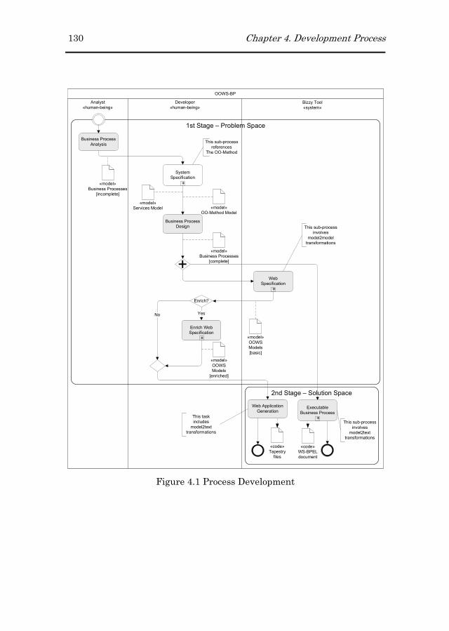
130 Chapter 4. Development Process
2nd Stage – Solution Space
1st Stage – Problem Space
OOWS-BP
Analyst
«human-being»
Developer
«human-being»
Business Process
Analysis
+
System
Specification
+
Web
Specification
Business Process
Design
Bizzy Tool
«system»
«model»
Business Processes
[incomplete]
«model»
OO-Method Model
«model»
Business Processes
[complete]
«model»
OOWS
Models
[basic]
«code»
WS-BPEL
document
Web Application
Generation
This sub-process
references
The OO-Method
This sub-process
involves
model2model
transformations
Enrich?
+
Enrich Web
Specification
YesNo
+
+
Executable
Business Process
«code»
Tapestry
files
«model»
OOWS
Models
[enriched]
This sub-process
involves
model2text
transformations
«model»
Services Model
This task
includes
model2text
transformations
Figure 4.1 Process Development

Chapter 4. Development Process 131
Structural
ModelFunctional
Model
Dynamic
Model
Sistem Object Life
Specification
State Changes
semantics
Specification
Information
Structure
Specification
External
Services
Specification
WSDL Services
Model
Figure 4.2 Expanded Sub-process System Specification
The following step in the process is still performed by the
developer. At this point, the developer completes20 the ABPs
defined by the Analyst in order to generate, in a later step, an
equivalent representation of the BPs but this time in terms of the
WS-BPEL executable language. This is achieved by associating
operations defined either in the Structural Model or in the
Services Model to the tasks included in the ABPs. These
associations will allow, in a later step of the process, to obtain
Concrete21 Business Processes (CBP).
20 This completion is only required when the ABP includes at least one
task that has not been defined as manual, this is, a task whose execution
is implemented in a system.
21 Understanding “concrete” as an executable definition of the process.

132 Chapter 4. Development Process
Once the system has been shaped in the previous mentioned
models we can bring them into the Bizzy tool and use it for the
generation of new artefacts (“Web Specification” task). This tool
performs two different tasks which produce different artefacts
from the specifications defined in the Structural, Services and
Business Process Models. On the one hand, the tool generates the
Navigational and Presentation models defined by the OOWS
approach (see Figure 4.3). On the other hand, from the CBPs the
tool generates the equivalent BP but this time as a WS-BPEL
process ready to be deployed in a process engine.
Figure 4.3 Expanded Sub-process Web Specification
4.3 The Modeling Step
This section presents the first step in the development process.
This step involves representing the system requirements in terms
of the models defined in the proposal.
4.3.14.3.14.3.14.3.1 The OOThe OOThe OOThe OO----Method Modeling Method Modeling Method Modeling Method Modeling StepStepStepStep
OO-Method provides a set of models that allow performing the
conceptual modelling of Information Systems. This conceptual
model is represented by two different aspects which are the

Chapter 4. Development Process 133
system structure and its behaviour. These two aspects are
gathered in the Structural, Dynamic and Functional models. In
addition to these models, an additional model was introduced in
(Torres et al., 2005; Quintero, 2008) to capture the functionality
that is provided by external systems. All these models are
explained in the following subsections.
4.3.1.14.3.1.14.3.1.14.3.1.1 The Structural ModelThe Structural ModelThe Structural ModelThe Structural Model
It defines the system structure (its classes, operations and
attributes) and relationships between classes by means of a UML
Class Diagram.
4.3.1.24.3.1.24.3.1.24.3.1.2 The Dynamic ModelThe Dynamic ModelThe Dynamic ModelThe Dynamic Model
It describes (1) the different valid object-life sequence for each
class of the system using State Transitions Diagrams and (2) the
communication between objects by means of Sequence Diagrams.
4.3.1.34.3.1.34.3.1.34.3.1.3 The Functional ModelThe Functional ModelThe Functional ModelThe Functional Model
It captures the semantics of the state changes to define service
effects using a textual formal specification.
4.3.24.3.24.3.24.3.2 The Services ModelThe Services ModelThe Services ModelThe Services Model
This model was introduced in the OOWS original proposal in order
to cope with the integration of external functionality into the
proposal. The objective of this model is bringing up external
services (functionality provided by external partners) into the
modelling level in order to manage them more easily.

134 Chapter 4. Development Process
4.3.34.3.34.3.34.3.3 The Business Process ModelThe Business Process ModelThe Business Process ModelThe Business Process Model
This model is used to specify the set of BPs that have to be
supported by the system. Its specification is performed by means
of the BPMN notation. The diagrams specified in this model are
built in two steps. First of all, a general description of the
processes is performed by the analyst. This description does not
include details in terms of the system, but in terms of the domain.
In a second step, these descriptions are taken and processed by
the developer in order to include all the details that will convert
them into process descriptions that can be transformed into
executable processes. This model is explained in detail in chapter
5.
4.3.44.3.44.3.44.3.4 The OOWS Method Modeling The OOWS Method Modeling The OOWS Method Modeling The OOWS Method Modeling StepStepStepStep
The OOWS Method extends the OO-Method approach in order to
cope with the peculiarities introduced by Web applications. It
defines three different models which gather three different aspects
of Web applications, (1) the kind of users interacting with the
system, (2) the way users can navigate through the system and (3)
the way the system is presented to the users.
4.3.4.14.3.4.14.3.4.14.3.4.1 The User ModelThe User ModelThe User ModelThe User Model
It defines the kind of users that are going to interact with the web
application. Moreover, it allows defining inheritance relationships
between them.

Chapter 4. Development Process 135
4.3.4.24.3.4.24.3.4.24.3.4.2 The Navigational ModelThe Navigational ModelThe Navigational ModelThe Navigational Model
It captures the navigational structure of Web applications. This
structure is defined as views over the system and different views
are defined for each kind of user defined in the User Model. The
extension to deal with the navigation modeling during BP
execution is presented in chapter 6.
4.3.4.34.3.4.34.3.4.34.3.4.3 The Presentation ModelThe Presentation ModelThe Presentation ModelThe Presentation Model
It defines the presentation properties in which the information
and functionality must be shown in the Web application. These
properties are related to information paging, layout and ordering
criteria and are applied to the elements that have been defined in
the Navigational Model.
4.4 The Code Generation Step
In a second step in the development process, the domain specified
in the models presented in the previous section is transformed into
code artefacts that can be executed. This phase of the process
includes two steps, one related with the generation of the code
representing the service orchestration (BPs) and another
representing the interface that will allow users involved in the
process interacting with the BPs. In particular, this interface is
going to be provided as a Web application.
4.4.14.4.14.4.14.4.1 WSWSWSWS----BPEL Code Generation StBPEL Code Generation StBPEL Code Generation StBPEL Code Generation Stepepepep
The generation process of an executable definition of the business
process is made up of three steps as Figure 4.4 shows.

136 Chapter 4. Development Process
Figure 4.4 Expanded Sub-process WS-BPEL generation
First of all, the “BPMN2BP-Babel” task takes as input the
abstract BPMN definition of the process and transforms it into the
BP format accepted by the Babel tool. This step is performed by
means of a model to model transformation (see section 9.2). Then,
the “Babel2WS-BPEL” task transforms the BP definition into a
partial WS-BPEL document (only the Activities section is
generated being the Partner Link, Variables and Correlation Sets
left). Then, the partial WS-BPEL document is completed in the
“WS-BPEL completion” task. This task can complete the WS-
BPEL definition from the information gathered in the Structural
and Services models. Finally, as a WS-BPEL process is also a web
service, it is necessary to generate its interface which contains
operations and data types. This is performed in the “WS-BPEL
WSDL + XSD” task.

Chapter 4. Development Process 137
4.4.24.4.24.4.24.4.2 UserUserUserUser Interface Code Generation Step Interface Code Generation Step Interface Code Generation Step Interface Code Generation Step
The generation process to obtain the modelled system into a Web
framework is performed in just one step (see Figure 4.5). In this
step a set of model-to-text transformations are executed to obtain
the modelled system in terms of a Web framework. Specifically,
these transformations produce code according to the Tapestry Web
framework. One of the main reasons to adopt this framework was
the component-based model in which this framework bases. This
allows marking a clear separation of different technologies used
during the development of the Web application.
Therefore, the “Web application generation” task requires the
OOWS model (including the OO-Method, the Services and the BP
models) as input model.
Figure 4.5 Expanded Sub-process Tapestry Web framework generation
138 Chapter 4. Development Process
As Figure 4.5 shows, the “Web framework files generation” task
produces three kinds of code files:
� The java files java files java files java files which define the java classes that
implement the logic of the application. It corresponds to
the Controller aspect from the MVC architecture in which
this framework relies on.
� The HTML filesHTML filesHTML filesHTML files which define the templates that
correspond to the View aspect from the MVC architecture.
� The page filespage filespage filespage files which are XML documents that include the
declaration of the Tapestry components used in the HTML
files. Although page files are optional, they contribute to
obtain a more readable code.
A more detailed explanation about the Tapestry framework and
the required files for building a Web application in this framework
is presented in chapter 9.
4.5 Conclusions
In this chapter we have presented the extended version of the
OOWS Web Engineering method to deal with the modelling and
generation process of BP-driven Web applications. The extension
involves the introduction of a new step in the modelling process to
specify the set of BP that the generated web application should
provide support to. Moreover, the generation process has been also
extended with a new step where BP definitions are transformed
into executable processes. Chapter 9 includes the set of

Chapter 4. Development Process 139
transformations that have been implemented to support the
generation process.

Chapter 5
5 Business Process Model
The Business Process Model (hereafther BPM) has been
introduced into the OOWS method to deal with the specification of
BPs at the modelling level. This model is based on the BPMN
notation. However, the expressivity provided by this notation does
not cover all the modelling requirements needed in the BPM. For
this reason, we have defined some extensions to the original
notation. These extensions allow us building BP specifications
that are integrated with other models defined in the method and
that can be automatically transformed into executable process
definitions (in particular in WS-BPEL definitions). These
extensions have been designed trying to modify the BPMN
original notation as little as possible. In fact, an extended model is
still a valid BPMN model (no structural or semantic changes have
been performed).
The chapter has been organized as follows. Section 5.2 present in
detail the modelling limitations found in the original BPMN
notation. Section 5.3 presents a BP example that highlights the
limitations previously presented. Then, by using the example,

142 Chapter 5. Business Process Model
section 5.4 details the extensions defined to deal with the
limitations. Finally, section 5.5 provides some conclusions.
5.1 Business Process Model based on the BPMN
notation
The BPM has been introduced in the OOWS original proposal to
provide developers with modelling mechanisms for the
specification of Business Processes (BP). This model allows
describing system functional requirements that are provided in
terms of a well-defined process. The type of information that is
represented in a BPM includes the set of tasks that form the
process and how these tasks are distributed among different
participants.
As we have stated in chapter 2, the BPM is specified by means of
the BPMN notation. This notation defines three basic types of sub-
models which are (1) private (internal) business processes, (2)
abstract (public) processes and (3) collaboration (global) processes.
In this work we combine two of these basic sub-models to model
BP requirements. On the one hand, private business processes are
used to define internal processes of a specific organization (for
which we are developing the system). On the other hand, abstract
processes are used to represent interactions between private
business processes and external participants.
The BPM is represented as a single Business Process Diagram
(hereafter BPD) that includes multiple private and abstract

Chapter 5. Business Process Model 143
processes where the activities that are common to several
processes are associated. In the last step of the development
process, by the application of model-to-model transformations,
each private business process is mapped to one WS-BPEL
document. Moreover, this document also includes the specification
of the interaction between the private process and the external
partners defined in the abstract processes. Specifically, this usage
of the BPMN notation corresponds with one of the types of BPD
covered by the notation (OMG, 2006), which corresponds to the
“Detailed private business process with interactions to one or more
external entities (or “Black Box” processes)” diagram type.
The information that has to be gathered in the BPM corresponds
to (1) the systems (external and internal) that are involved in the
BP, (2) the activities that conform the internal (private BP)
system, (3) the participants (within the private BP) that are
responsible of performing these activities, (4) the conditions that
control the BP flow and (5) the interaction that occurs between the
private BP and the external partner(s). To represent all this
information in a BPD, the BPMN notation provides us with
different elements that allow representing the information that
need to be specified in the BPM. These elements have already
been presented in chapter 2 but the main groups are briefly
presented now.
� SwimlanesSwimlanesSwimlanesSwimlanes: The elements included in this group allow
grouping primary modeling elements. These elements are
Pools, and Lanes and are defined in the specification as
follows:
144 Chapter 5. Business Process Model
� ArtifactsArtifactsArtifactsArtifacts: The elements included in this group are used to
provide additional information about the Process.
Nowadays, the BPMN specification includes Data Object,
Group and Annotation, however, this set is susceptible to
grow and standardize either for general use or for vertical
markets. A common characteristic of the elements included
in this group is that none of them have a direct effect on
the Sequence or Message Flow of the Process.
� Flow ObjectsFlow ObjectsFlow ObjectsFlow Objects: The elements included in this group define
the behaviour of a BP. These elements are Events,
Activities and Gateways.
� Connecting ObjectsConnecting ObjectsConnecting ObjectsConnecting Objects: The elements included in this group
allow connecting Flow Objects to each other. The
specification distinguishes three kind of connecting objects
which are Sequence Flow, Message Flow and Association.
5.2 BPMN limitations to Support the BPM
The four groups of elements roughly presented in the previous
section gather the set of graphical elements used in the BPD.
However, in order to produce executable definitions equivalent to
those modelled in the BPMN notation it is necessary to provide
detailed information to some of the elements conforming these
BPs. Within the set of BPMN graphical objects we find almost all
the necessary elements for defining the kind of processes we are
interested in. Nevertheless, the notation does not allow us
defining:

Chapter 5. Business Process Model 145
1. The scenarios where human participants behave as individuals
or as members of a particular group.
2. The functionality that is going to support each task/activity
included in the BP definition. Note however that this do not
applies to tasks defined as manual (tasks that do not change
the state of the Information System and that are completely
carried out by users).
3. Dependencies between different lanes within the same pool. In
some cases process participants are related each other and this
link have to be explicitly defined in the process.
To deal with these limitations we have defined extensions to the
original BPMN notation. Specifically, the proposed extensions
have been defined over the BPMN Metamodel included in the
BPMN modeller22 from the STP (SOA Tools Platform) project. The
modeller main goal is to provide a graphical notation that allows
defining processes. This tool has been developed based on GMF
(Graphical Modeling Framework) and reuses and extends the GEF
(Graphical Editing Framework) and the EMF (Eclipse Modeling
Framework) projects.
5.3 PhD Thesis Delivery Example
The PhD Thesis Delivery BP depicted in Figure 5.1 represents the
procedure defined by a University Department to present a PhD
Thesis work. This BP is fully performed by participants of the
same organization (all of them are defined in different lanes
22 http://www.eclipse.org/stp/bpmn/
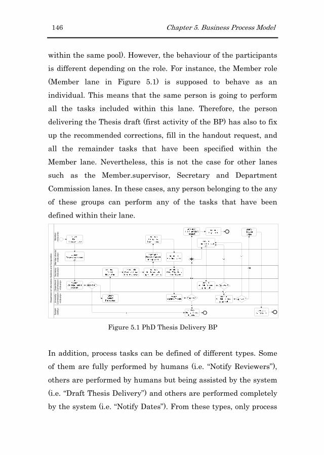
146 Chapter 5. Business Process Model
within the same pool). However, the behaviour of the participants
is different depending on the role. For instance, the Member role
(Member lane in Figure 5.1) is supposed to behave as an
individual. This means that the same person is going to perform
all the tasks included within this lane. Therefore, the person
delivering the Thesis draft (first activity of the BP) has also to fix
up the recommended corrections, fill in the handout request, and
all the remainder tasks that have been specified within the
Member lane. Nevertheless, this is not the case for other lanes
such as the Member.supervisor, Secretary and Department
Commission lanes. In these cases, any person belonging to the any
of these groups can perform any of the tasks that have been
defined within their lane.
System
«entity»
Department of Information Systems and Computation
Member
«role-one»
Department
Commission
«role-any»
Secretary
«role-any»
University
Commission
«role-any»
Member.director
«role-any»
Figure 5.1 PhD Thesis Delivery BP
In addition, process tasks can be defined of different types. Some
of them are fully performed by humans (i.e. “Notify Reviewers”),
others are performed by humans but being assisted by the system
(i.e. “Draft Thesis Delivery”) and others are performed completely
by the system (i.e. “Notify Dates”). From these types, only process

Chapter 5. Business Process Model 147
tasks included in the last two types are associated with some
system functionality. Figure 5.2 depicts (1) an enlarged excerpt of
the PhD Thesis Delivery BP and (2) an excerpt of the Structural
Model built for this example.
Figure 5.2 Excerpts of the Structural Model and Business Process
Diagram
Another particularity of the PhD Thesis Delivery BP is that the
specific supervisors involved in the process depend on the member
delivering the thesis. On the contrary, other participants such as
the Secretary Staff, the Department and the University
Commissions are always the same independently of the specific
user delivering the thesis.
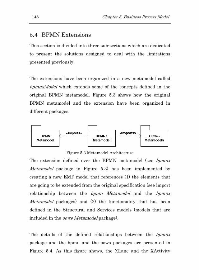
148 Chapter 5. Business Process Model
5.4 BPMN Extensions
This section is divided into three sub-sections which are dedicated
to present the solutions designed to deal with the limitations
presented previously.
The extensions have been organized in a new metamodel called
bpmnxModel which extends some of the concepts defined in the
original BPMN metamodel. Figure 5.3 shows how the original
BPMN metamodel and the extension have been organized in
different packages.
Figure 5.3 Metamodel Architecture
The extension defined over the BPMN metamodel (see bpmnx
Metamodel package in Figure 5.3) has been implemented by
creating a new EMF model that references (1) the elements that
are going to be extended from the original specification (see import
relationship between the bpmn Metamodel and the bpmnx
Metamodel packages) and (2) the functionality that has been
defined in the Structural and Services models (models that are
included in the oows Metamodel package).
The details of the defined relationships between the bpmnx
package and the bpmn and the oows packages are presented in
Figure 5.4. As this figure shows, the XLane and the XActivity

Chapter 5. Business Process Model 149
classes extend the Lane and Activity concepts defined in the
BPMN original metamodel.
Figure 5.4 Extension Defined to the BPMN Metamodel
The following subsections explain each extension. This
explanation is carried out in two steps. First, a concrete syntax
based on the example presented in section 5.3 is provided. Then,
the abstract syntax of the introduced elements (concepts and
relationships) is performed.
5.4.15.4.15.4.15.4.1 Differentiating Human Participant BehaviourDifferentiating Human Participant BehaviourDifferentiating Human Participant BehaviourDifferentiating Human Participant Behaviour
Concrete SyntaxConcrete SyntaxConcrete SyntaxConcrete Syntax: : : : In the PhD Thesis Delivery BP, the Member
lane has been marked with the “role-one” value. On the contrary,
the remainder lanes have been marked with the “role-any” value.
Abstract Abstract Abstract Abstract SyntaxSyntaxSyntaxSyntax: : : : In order to differentiate the behaviour of a
process role we have extended the Lane element with a new
attribute, the type attribute. The values accepted by this new
attribute are role-one and role-any.
150 Chapter 5. Business Process Model
� The role-one value is used when the user behaves as an
individual. Therefore, the human being performing the first
task of the lane has to be the same for the rest of tasks
defined within the same lane.
� The role-any value is used when the user behaves as a
member of a group. In this case, any human being
belonging to the group specified in the lane can perform
any of the tasks included in it.
Specifically, this extension has been implemented by adding the
type attribute to a new class, the XLane class, which extends from
the Lane class defined in the original BPMN notation. This
attribute has been designed as follows:
� The type attribute has been introduced to specify the
behaviour of the role involved in the current lane. It can
take one of the three different values: entity (used when
the participant is not a human being), roleOne (used when
the participant is a human being that participates in the
current process as an individual) or roleAny (used when the
participant is a human being that participates in the
current process as a member of a group). These values are
defined in the XlaneType enumeration.
5.4.25.4.25.4.25.4.2 Defining the Functionality of each Process TaskDefining the Functionality of each Process TaskDefining the Functionality of each Process TaskDefining the Functionality of each Process Task
Concrete SyntaxConcrete SyntaxConcrete SyntaxConcrete Syntax: : : : In the PhD Thesis Delivery BP, tasks defined as
“user” and “service” has to be linked to operations defined in the
Structural Model. For instance, the first activity “Draf Thesis
delivery”, which is defined as “user”, is associated with the

Chapter 5. Business Process Model 151
“handInThesis()” operation defined in the Thesis class (see Figure
5.2). In this activity, the user inputs the required data (specifically
the data required by the operation) and the system executes the
operation which creates (1) an instance of the process and (2) an
instance of the thesis class. Similarly, the “Propose reviewers”,
“Validate Thesis proposal” and “Select Reviewers” activities are
associated with the “Collaborator.newRevisor()”,
“Thesis.setState()” and “Collaborator.setState()” operations
respectively.
Abstract SyntaxAbstract SyntaxAbstract SyntaxAbstract Syntax: : : : A necessary step to obtain an executable
definition of the process is specifying the functionality that is
going to be performed in each task. For this purpose, we have
extended the Task element with a new attribute, the operation
attribute, which associates tasks with functionality that has been
defined in the Structural or in the Services Model. On the one
hand, the Structural Model defines functionality that is provided
by the local system, specifically by the classes defined in it. On the
other hand, the Services Model defines functionality that is
provided by external systems, specifically by the imported Web
services. However, this extension only applies to tasks defined as
Service, Receive, Send and User (these are some of the types in
which a task process can be defined) in the BPMN notation.
Process tasks defined as Script or Manual are not susceptible of
this extension.

152 Chapter 5. Business Process Model
Specifically, this extension has been implemented by adding the
operation attribute to the XLane class. This attribute has been
designed as follows:
� The operation attribute is used to reference an operation
defined either in the Structural model or in the Services
model.
5.4.35.4.35.4.35.4.3 Lane DependencesLane DependencesLane DependencesLane Dependences
Concrete SynConcrete SynConcrete SynConcrete Syntax:tax:tax:tax: In the PhD Thesis Delivery BP, the “dynamic”
lane has been labelled as “Member.supervisor” indicating the
dependent lane (Member) and the relationship between these two
lanes (supervisor). In addition, the role-dependence attribute has
set to the navigation expression: Thesis.isSupervisedBy which
allows identifying the users that can perform the tasks included in
the Member.supervisor lane. With regard to the order in which
tasks have to be performed, Figure 5.1 shows that the “Draft
Thesis delivery” task in charge of creating an object of the Thesis
class is performed previously to the “Propose Reviewers” task
which can be performed by any of the supervisors associated to the
Thesis previously delivered.
Abstract SyntaxAbstract SyntaxAbstract SyntaxAbstract Syntax: : : : In order to define dependencies between
different roles included in the BP we have extended the Lane
element with a new attribute, the role-dependence attribute. This
attribute is valued with an expression linked to the Structural
Model that allows identifying the users that form this “dynamic”
role. This expression corresponds to navigation over associations
defined in the Structural Model. In addition, this dependency
Chapter 5. Business Process Model 153
forces to perform first the activities that create or selects the
object involved in the navigation expression. Finally, to identify
more easily dependencies between lanes we label “dynamic” lanes
as follows: [dependent_lane].[relationship].
Specifically, this extension has been implemented by adding the
role-dependence attribute to the XLane class. This attribute has
been designed as follows:
� The role-dependence attribute has been introduced to
specify the dependence of the current lane with another
lane defined within the same pool. This relationship has to
be expressed in terms of the relationship defined in the
Structural model between these users. The notation used to
define this link is related with the relationship defined in
the Structural model.
5.5 Conclusions
Business Process models play a very important role in the
development process of enterprise software systems. Although
depending on the area in which enterprises develop their
functionality, it is quite likely that some of the requirements of the
system were given as a process. Then, once these process
specifications are given, these can serve as two purposes. On the
one hand, it allow business analysts to define clearly (as these
specifications are usually performed in languages or notations
targeted to this kind of users) the business process that systems
should implement. On the other hand, these specifications can
154 Chapter 5. Business Process Model
also be used as input in the development process to derive new
artefacts (executable process definitions and graphical user
interfaces) related to it.
This chapter has presented a set of extensions defined over the
original BPMN notation. The main reason to define these
extensions is integrating BP specifications into the OOWS
approach and detailing these specifications to transform them into
an executable language.
Finally, the availability of tools developed under the umbrella of
the Eclipse project (and in particular the use of the EMF project),
as it is the case of the BPMN modeller, has facilitated the
development of the proposed extension.
Summing up, the introduction of the Business Process Model with
the characteristics that have been explained in this chapter
endows the method to overcome seamlessly the development of
Web applications that are highly driven by Business Processes.

Chapter 6
6 Navigational Model Extension
This chapter presents the extensions that have been introduced
into the OOWS Navigational Model to deal with the integration of
Business Processes (BP). These extensions have been designed
taking into account the characteristics of the kind of BPs (short-
running and long-running BPs) we are dealing with (see chapter
2). The main reason to introduce new primitives is to be consistent
with the separation of concerns in which the OOWS method has
been conceived since its inception.
The chapter has been structured as follows. Section 6.1 provides
an introduction to this chapter. In this section, a motivation for
the introduction of these primitives is provided. Then, the
extension is presented through the following three sections. First,
in section 6.2 the extension is presented intuitively by means of
two case studies. Second, a more formal description of these
primitives is presented in section 6.3. Third, an overview of the
Navigational metamodel is presented in section 6.4. Finally,
section 6.5 presents the conclusions of this chapter.

156 Chapter 6. Navigational Model Extension
6.1 Introduction
The interaction that takes place between the user and the system
during the execution of a BP is different from the one occurring
during content navigation. On the one hand, when the user
navigates through the Web application (content navigation), she is
the one deciding the path (link) to follow. On the other hand, when
the user is executing a BP (BP navigation), is the system that
drives the user through the application.
The set of new primitives presented in this chapter allow
capturing, relating and manipulating the different aspects that
are introduced by the execution of BPs which are:
� The required data and functionality to perform BP
activities. The required functionality is specified by means
of the class-view, service-data-view and service-functional-
view primitives. These primitives are views over classes
and services defined in the Structural and Services Models
respectively and define the data and functionality that is
associated to a specific BP activity.
� The access point that allow users reaching BPs. This access
points allow users (1) starting new instances of a specific
BP and (2) taking up again a started BP instance that was
previously suspended. This is specified by means of the
Process Context and the Process Link primitive.
� Complementary information that help users completing BP
tasks. By providing users with information related to the
BP activities being performed we (1) help them in
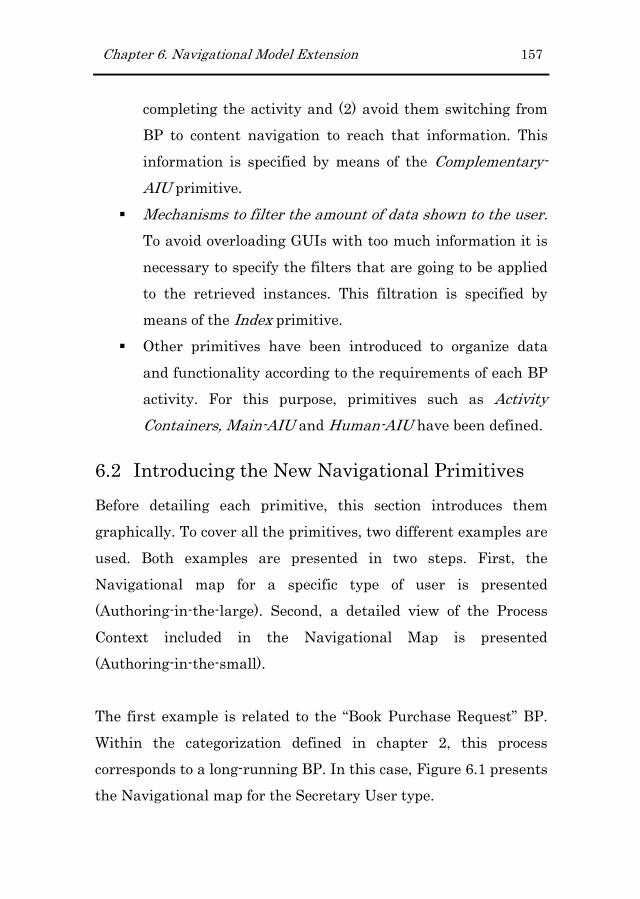
Chapter 6. Navigational Model Extension 157
completing the activity and (2) avoid them switching from
BP to content navigation to reach that information. This
information is specified by means of the Complementary-
AIU primitive.
� Mechanisms to filter the amount of data shown to the user.
To avoid overloading GUIs with too much information it is
necessary to specify the filters that are going to be applied
to the retrieved instances. This filtration is specified by
means of the Index primitive.
� Other primitives have been introduced to organize data
and functionality according to the requirements of each BP
activity. For this purpose, primitives such as Activity
Containers, Main-AIU and Human-AIU have been defined.
6.2 Introducing the New Navigational Primitives
Before detailing each primitive, this section introduces them
graphically. To cover all the primitives, two different examples are
used. Both examples are presented in two steps. First, the
Navigational map for a specific type of user is presented
(Authoring-in-the-large). Second, a detailed view of the Process
Context included in the Navigational Map is presented
(Authoring-in-the-small).
The first example is related to the “Book Purchase Request” BP.
Within the categorization defined in chapter 2, this process
corresponds to a long-running BP. In this case, Figure 6.1 presents
the Navigational map for the Secretary User type.
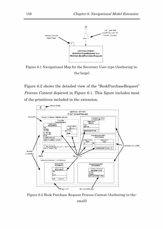
158 Chapter 6. Navigational Model Extension
Figure 6.1 Navigational Map for the Secretary User type (Authoring-in-
the-large)
Figure 6.2 shows the detailed view of the “BookPurchaseRequest”
Process Context depicted in Figure 6.1. This figure includes most
of the primitives included in the extension.
Figure 6.2 Book Purchase Request Process Context (Authoring-in-the-
small)

Chapter 6. Navigational Model Extension 159
The second example is related to the “Checkout” BP. Within the
categorization defined in chapter 2, this process corresponds to a
short-running BP.
Figure 6.3 Navigational Map for the Member User type (Authoring-in-
the-large)
In this case, Figure 6.3 presents the Navigational map defined for
the Secretary User type.
Finally, Figure 6.4 shows the detailed view of the “Checkout”
Process Context depicted in Figure 6.3.
Figure 6.4 Check Out Process Context (Authoring-in-the-small)

160 Chapter 6. Navigational Model Extension
Along this chapter, these figures are referenced to explain the
primitives included in it.
6.3 Navigational Primitives to Support BP
execution
The extension defined over the Navigational Model defines ten
primitives, which include new ones and others that have been
adapted to the context of BPs. All these primitives represent an
abstraction of the elements included in the GUI used for
completing BPs. The new primitives are Process Context, Activity
Container, Main-AIU, Human-AIU, Complementary-AIU, Service-
Data-view, Service-Functional-view and Process-link. The adapted
ones are Index and Class-view. Each primitive is going to be
presented according to this schema: First, the problem that
motivates the definition of the current primitive is presented.
Second, the concrete syntax of the primitive is presented. This
syntax is described in a diagrammatic form and defines how the
abstract syntax (which is presented next) is presented to the end
user. Finally, the abstract syntax of the primitive is presented. In
this case, the concepts associated to the primitive and their
relationships to other primitives (even from another metamodel)
are described.
6.3.16.3.16.3.16.3.1 Process ContextProcess ContextProcess ContextProcess Context
ProblemProblemProblemProblem: We need to specify which GUIs are associated to a
particular BP. In addition, it is necessary to specify how a BP is

Chapter 6. Navigational Model Extension 161
reached, this is, which navigational paths have to be followed to
reach a specific BP.
Concrete SyntaConcrete SyntaConcrete SyntaConcrete Syntaxxxx: Figure 6.2 and Figure 6.4 illustrate a detailed
view (authoring-in-the-small) of the “Book Purchase Request” and
“Checkout” BPs respectively. With regard to the “Book Purchase
Request” BP, the process context has been defined as
“Exploration” context and has been associated to the Secretary
User type. This means that users belonging to the Secretary User
type can reach this Process Context from any place of the Web
application. In addition, this Process Context has been defined
from the “Book Purchase Request” Process Context specified for
the Member User type (this is possible because in the User Model
we have defined an inheritance relationship between the Member
and the Secretary User types). This inheritance mechanism allows
redefining contexts based on the user responsibilities.
The strategy proposed to allow users reaching long-running BPs
defined as “Exploration” context, is to gather these BPs into a
specific section called “Processes”. Figure 6.5 illustrates the Web
page corresponding to this “Processes” section. In addition, this
section includes the “my TODO List” section which provides the
logged users a shortcut to access their pending tasks.

162 Chapter 6. Navigational Model Extension
Figure 6.5 Web page corresponding to the “Processes” Section
With regard to the “Checkout” BP example, this has been defined
as “Sequence” context and has been associated to the Member
User type. This means that users belonging to the Member User
type can reach this Process Context throughout the “Shopping
Cart” Navigational Context. Figure 6.6 illustrates the
implementation of the “Shopping Cart” Navigational Context. In
this Web page, a link to start the “Check Out” BP is provided to
the user.

Chapter 6. Navigational Model Extension 163
Process Link to
Start the “Check Out” BP
Figure 6.6 Web page corresponding to the “Shopping Cart” Navigational
Context
A generic diagram of this primitive is shown in Figure 6.7. As this
figure shows, a detailed view of a Process Context is depicted
graphically as a UML package stereotyped with the keyword
«process-context» (see the white part of Figure 6.7) and containing
the name that corresponds to the referred process.
Figure 6.7 Process-Context primitive
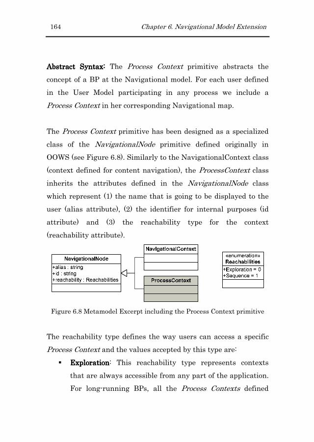
164 Chapter 6. Navigational Model Extension
Abstract Syntax: Abstract Syntax: Abstract Syntax: Abstract Syntax: The Process Context primitive abstracts the
concept of a BP at the Navigational model. For each user defined
in the User Model participating in any process we include a
Process Context in her corresponding Navigational map.
The Process Context primitive has been designed as a specialized
class of the NavigationalNode primitive defined originally in
OOWS (see Figure 6.8). Similarly to the NavigationalContext class
(context defined for content navigation), the ProcessContext class
inherits the attributes defined in the NavigationalNode class
which represent (1) the name that is going to be displayed to the
user (alias attribute), (2) the identifier for internal purposes (id
attribute) and (3) the reachability type for the context
(reachability attribute).
Figure 6.8 Metamodel Excerpt including the Process Context primitive
The reachability type defines the way users can access a specific
Process Context and the values accepted by this type are:
� ExplorationExplorationExplorationExploration: This reachability type represents contexts
that are always accessible from any part of the application.
For long-running BPs, all the Process Contexts defined

Chapter 6. Navigational Model Extension 165
according this type are gathered in an always accessible
section called “Processes”.
� SequenceSequenceSequenceSequence: This reachability type represents contexts that
are only accessible by means of a predefined path. This sort
of contexts is reached through a set of chained Navigational
Contexts whose last context in the chain includes a link to
the Process Context (see Process-link in 6.3.10 subsection).
6.3.26.3.26.3.26.3.2 Activity ContainerActivity ContainerActivity ContainerActivity Container
ProblemProblemProblemProblem: We need to specify the data and functionality that is
associated to a specific BP activity.
Concrete SyntaxConcrete SyntaxConcrete SyntaxConcrete Syntax: Figure 6.2 and Figure 6.4 define two Process
Contexts which include different Activity Containers, specifically,
one per each activity defined in the BP involving human
participation. Each Activity Container gathers all the data and
functionality that are necessary to complete the associated BP
activity.
Figure 6.9 illustrates how the “Validate Request” Activity
Container included in the “Book Purchase Request” BP (see Figure
6.2) is presented at the implementation level.
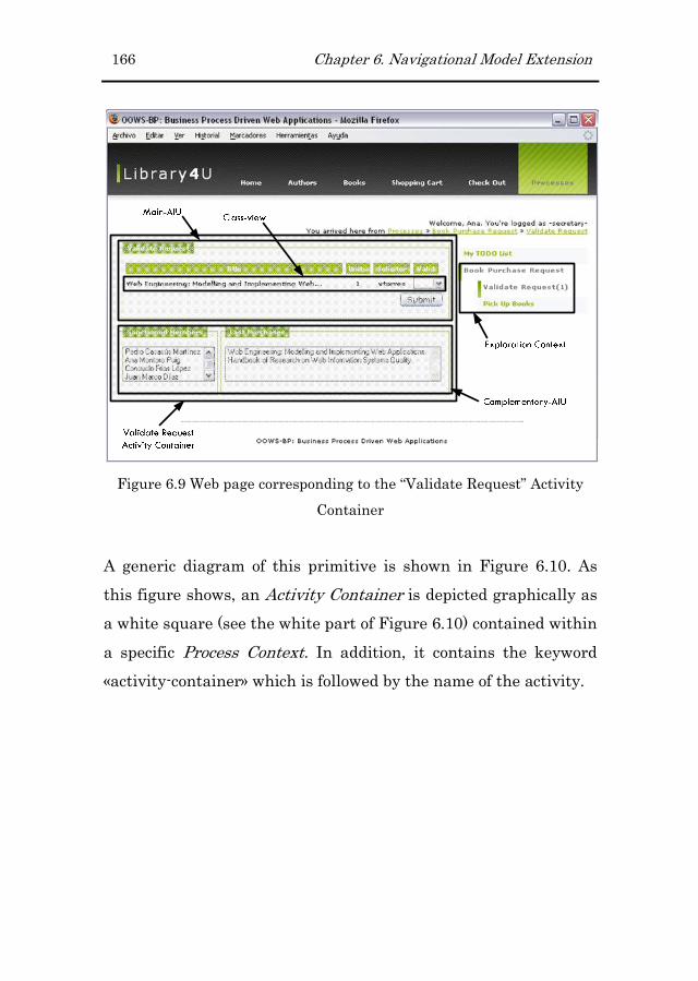
166 Chapter 6. Navigational Model Extension
Figure 6.9 Web page corresponding to the “Validate Request” Activity
Container
A generic diagram of this primitive is shown in Figure 6.10. As
this figure shows, an Activity Container is depicted graphically as
a white square (see the white part of Figure 6.10) contained within
a specific Process Context. In addition, it contains the keyword
«activity-container» which is followed by the name of the activity.

Chapter 6. Navigational Model Extension 167
Figure 6.10 Activity-Container primitive
Abstract SyntaxAbstract SyntaxAbstract SyntaxAbstract Syntax: The Activity Container primitive abstracts the
concept of a BP activity at the Navigational model. It is contained
within the Process Context primitive previously presented. Each
activity modelled in the Business Process Model (BPM) and
defined as «user» or «manual» will have a corresponding Activity
Container in the Navigational Model. This primitive gathers the
required data and functionality that has to be provided in the GUI
to the user to complete the corresponding BP activity. An Activity
Container is made up of different Abstract Information Units23
(AIU). An Activity Container must include either a Main-AIU or
Human-AIU and zero or many Complementary-AIUs (these
primitives are explained in sections 6.3.3, 6.3.4 and 6.3.5
respectively). This constraint is defined in the metamodel by
23 An AIU is defined in the original proposal as a “primitive representing
the requirement of retrieving a chunk of related information”. This
primitive allows the coexistence of different information units in the
same web page (requirement that is usually demanded in Web portals).

168 Chapter 6. Navigational Model Extension
means of a multiplicity restriction defined between the Activity
Container and the abstract BaseAIU classes (the BaseAIU
generalizes the Main-AIU and the Human-AIU classes). Activity
Containers define two attributes which are initial and
createProcessInstance. On the one hand, the initial attribute is
valued to true when the Activity Container corresponds to the first
activity of the process requiring interaction with a human being.
Within the same Process Context, no more than one Activity
Container can be defined as initial. This means that the BP is
started by the user associated to the Process Context. On the
contrary, when no Activity Containers are defined as initial, the
BP is started by a system. This constraint is expressed in the OCL
language as follows:
Context ProcessContext
inv: (self.activities.initial->select(a|a = true))->size() = 1
On the other hand, the createProcessInstance attribute is valued
to true when the Activity Container represents the first activity of
the process (independently of its type). Moreover, only Activity
Containers whose initial attribute is set to true can value their
createProcessInstance attribute to true. The reason is that only
the initial activities can create an instance of the associated BP.
This constraint is expressed in the OCL language as follows:
Context ProcessContext
inv: (self.activities.initial->select(a|a = false))->union (
(self.activities.createprocessinstance->select(a|a = true)))->size()= 0

Chapter 6. Navigational Model Extension 169
As Figure 6.11 shows, since the Activity Container primitive is
“part of” the Process Context primitive, a composition relationship
between these two classes. With regard to the definition of an
Activity Container, this defines four attributes to indicate (1) an
internal identifier (id attribute), (2) the name used to be displayed
to the user (alias attribute), (3) if the Activity Container
corresponds to the first activity of the process requiring
interaction with humans (initial attribute) and (4) if the Activity
Container corresponds to the first activity of the process
(createProcessInstance attribute).
Figure 6.11 Metamodel Excerpt including the Activity Container
primitive
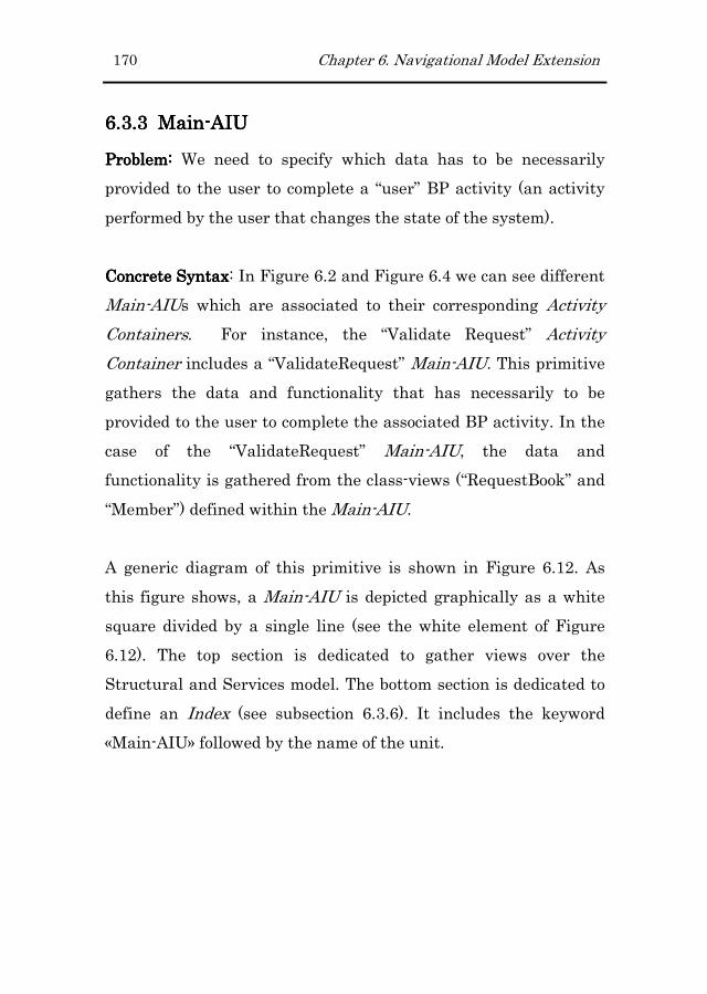
170 Chapter 6. Navigational Model Extension
6.3.36.3.36.3.36.3.3 MainMainMainMain----AIUAIUAIUAIU
Problem: Problem: Problem: Problem: We need to specify which data has to be necessarily
provided to the user to complete a “user” BP activity (an activity
performed by the user that changes the state of the system).
Concrete SyntaxConcrete SyntaxConcrete SyntaxConcrete Syntax: In Figure 6.2 and Figure 6.4 we can see different
Main-AIUs which are associated to their corresponding Activity
Containers. For instance, the “Validate Request” Activity
Container includes a “ValidateRequest” Main-AIU. This primitive
gathers the data and functionality that has necessarily to be
provided to the user to complete the associated BP activity. In the
case of the “ValidateRequest” Main-AIU, the data and
functionality is gathered from the class-views (“RequestBook” and
“Member”) defined within the Main-AIU.
A generic diagram of this primitive is shown in Figure 6.12. As
this figure shows, a Main-AIU is depicted graphically as a white
square divided by a single line (see the white element of Figure
6.12). The top section is dedicated to gather views over the
Structural and Services model. The bottom section is dedicated to
define an Index (see subsection 6.3.6). It includes the keyword
«Main-AIU» followed by the name of the unit.

Chapter 6. Navigational Model Extension 171
Figure 6.12 Main-AIU primitive
Abstract SyntaxAbstract SyntaxAbstract SyntaxAbstract Syntax: This primitive gathers all the data and
functionality required by the user to perform a specific task. It is
divided into two sections; (1) one that includes views over the
Structural model (see Class-view) or the Services model (see
Service-functinoal-view) and (2) another that defines the way data
is going to be shown when the AIU retrieves more than one
instance (see the Index primitive presented in section 6.3.6).
The Main-AIU primitive has been defined as a specialized class of
the Base-AIU abstract class. The reason to introduce this abstract
class is to represent the constraint previously presented that
states that “An Activity Container can only include either one
Main-AIU or one Human-AIU”. In turn, this abstract class
inherits from the AIU class which defines attributes to represent
(1) an internal identifier (id attribute), (2) a string used for

172 Chapter 6. Navigational Model Extension
identifying the AIU at the user interface (alias attribute) and (3)
the relationship between this AIU and the Context in which this
AIU belongs (isContextual attribute).
Figure 6.13 Metamodel Excerpt including the Main-AIU primitive
A particularity introduced by this primitive is that within a Main-
AIU, the included views (class-views or service-functional-views)
can only specify one operation. Specifically, this operation
corresponds to the functionality that supports the associated BP
activity. This constraint is expressed in the OCL language as
follows:
Context MainAIU
inv: (self.ManagerClass.NavigationalOperation->size() = 1) or
(self.ComplementaryClass.NavigationalOperation->size() = 1)
When the class-views or services-data-views included in the Main-
AIU retrieve more than one instance, the Main-AIU primitive
activates the Index defined in its bottom section. As a result, it
filters the data defined in the views and shows just the attributes
specified in the attribute section of the Index.

Chapter 6. Navigational Model Extension 173
6.3.46.3.46.3.46.3.4 HumanHumanHumanHuman----AIUAIUAIUAIU
Problem: Problem: Problem: Problem: We need to specify which data has to be necessarily
provided to the user to complete a “human” BP activity.
Concrete SyntaxConcrete SyntaxConcrete SyntaxConcrete Syntax: In Figure 6.2 we can see the “PickUpBooks”
Human-AIU associated to the “PickUpBooks” Activity Container.
This primitive gathers the data that has necessarily to be provided
to the user to complete the associated BP activity. In this case, the
data is gathered from the class-views defined within the Human-
AIU.
Figure 6.14 shows how the Human-AIU modelled in Figure 6.2 is
implemented in a Web page. In this case, the event associated to
the “submit” button does not invoke any functionality. It only
communicates the BP that the current BP activity has been
completed.

174 Chapter 6. Navigational Model Extension
Figure 6.14 Implementation of a Human-AIU
A generic diagram of this primitive is shown in Figure 6.15. As
this figure shows, a Human-AIU is depicted graphically as a white
rectangle that includes the keyword «Human-AIU» followed by the
name of the unit (see the white part of Figure 6.15). Moreover, this
primitive display data related to the activity being performed
(usually a description of the tasks to perform).

Chapter 6. Navigational Model Extension 175
Figure 6.15 Human-AIU primitive
Abstract SyntaxAbstract SyntaxAbstract SyntaxAbstract Syntax: This primitive represents BP activities defined in
the BPM that are not automated in the system (activities that are
fully performed without the assistance of any system).
Similar to the Main-AIU primitive, the Human-AIU primitive has
been designed as a child class from the Base-AIU abstract class. In
addition to the attributes inherited from the AIU class, the
Human-AIU primitive includes the description attribute which is
used to include information that is going to be presented to the
user when the corresponding Human-AIU gets activated.
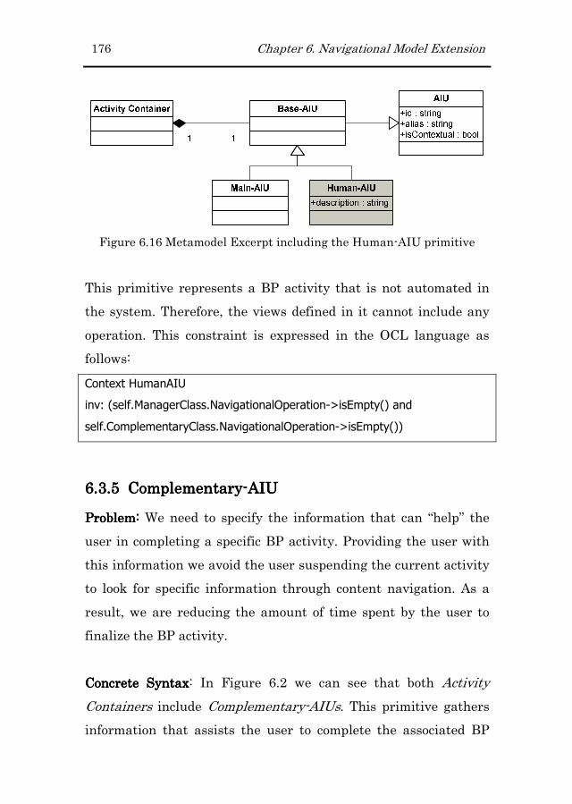
176 Chapter 6. Navigational Model Extension
Figure 6.16 Metamodel Excerpt including the Human-AIU primitive
This primitive represents a BP activity that is not automated in
the system. Therefore, the views defined in it cannot include any
operation. This constraint is expressed in the OCL language as
follows:
Context HumanAIU
inv: (self.ManagerClass.NavigationalOperation->isEmpty() and
self.ComplementaryClass.NavigationalOperation->isEmpty())
6.3.56.3.56.3.56.3.5 ComplementaryComplementaryComplementaryComplementary----AIUAIUAIUAIU
Problem: Problem: Problem: Problem: We need to specify the information that can “help” the
user in completing a specific BP activity. Providing the user with
this information we avoid the user suspending the current activity
to look for specific information through content navigation. As a
result, we are reducing the amount of time spent by the user to
finalize the BP activity.
Concrete SyntaxConcrete SyntaxConcrete SyntaxConcrete Syntax: In Figure 6.2 we can see that both Activity
Containers include Complementary-AIUs. This primitive gathers
information that assists the user to complete the associated BP

Chapter 6. Navigational Model Extension 177
activity. In this case, the information is retrieved by means of
class-views and service-data-views defined within the
corresponding Activity Containers.
A generic diagram of this primitive is shown in Figure 6.17. As
this figure shows, a Complementary-AIU is depicted graphically
as a white rectangle that includes the keyword «Complementary-
AIU» followed by the name of the unit (see the white part of
Figure 6.17).
Figure 6.17 Complementary-AIU primitive
Similar to Human-AIUs, this primitive gathers views over the
system (from the Structural and Services models) with the
particularity that no functionality can be defined in it.
Abstract Syntax: Abstract Syntax: Abstract Syntax: Abstract Syntax: This primitive was introduced to assist the user
while she is performing a specific task. It provides additional
information that may help her in completing it. This AIU is not

178 Chapter 6. Navigational Model Extension
strictly necessary to perform the task but avoids the user leaving
the execution of the process to reach this information through
content navigation. The objective of this AIU is to speed up the
completion of the process providing the user with useful
information. Contrary to other primitives, this one cannot be
derived automatically from the BP definition. In this case, the
developer has to include it manually. For this reason, during the
specification of the BP, the analyst specifies (in a textual form) the
information that should be provided associated to each BP
activity. This textual description will be used by the developer to
decide the complementary units that should be included for each
Activity Container.
Complementary-AIUs are optional units within a particular
Activity Container. This constraint is defined by the multiplicity of
the composition association defined between these two primitives.
Moreover, the Complementary-AIU class inherits the three
attributes defined in the AIU class.
Figure 6.18 Metamodel Excerpt including the Complementary-AIU
primitive
Since Complementary-AIUs are used to provide some useful data
related to the current BP activity, the views defined in it cannot
specify any operation. These views can only retrieve information,
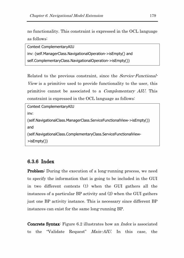
Chapter 6. Navigational Model Extension 179
no functionality. This constraint is expressed in the OCL language
as follows:
Context ComplementaryAIU
inv: (self.ManagerClass.NavigationalOperation->isEmpty() and
self.ComplementaryClass.NavigationalOperation->isEmpty())
Related to the previous constraint, since the Service-Functional-
View is a primitive used to provide functionality to the user, this
primitive cannot be associated to a Complementary AIU. This
constraint is expressed in the OCL language as follows:
Context ComplementaryAIU
inv:
(self.NavigationalClass.ManagerClass.ServiceFunctionalView->isEmpty())
and
(self.NavigationalClass.ComplementaryClass.ServiceFunctionalView-
>isEmpty())
6.3.66.3.66.3.66.3.6 IndexIndexIndexIndex
Problem: Problem: Problem: Problem: During the execution of a long-running process, we need
to specify the information that is going to be included in the GUI
in two different contexts (1) when the GUI gathers all the
instances of a particular BP activity and (2) when the GUI gathers
just one BP activity instance. This is necessary since different BP
instances can exist for the same long-running BP.
Concrete SyntaxConcrete SyntaxConcrete SyntaxConcrete Syntax: Figure 6.2 illustrates how an Index is associated
to the “Validate Request” Main-AIU. In this case, the

180 Chapter 6. Navigational Model Extension
“ATTRIBUTES” section specifies that the book title, units and the
login of the applicant member are going to be retrieved for each
instance retrieved by the Main-AIU. In addition, the “LINK
ATTRIBUTE” section states that the “title” field is going to be
used as anchor to reach the selected instance.
A generic diagram of this primitive is shown in Figure 6.19. As
this figure shows, an Index is depicted graphically as a white box
attached to the bottom section of a Main-AIU (see the white part
of Figure 6.19). Its definition is merely textual and includes three
attributes which are (1) the index name, (2) a list of attributes
that are shown when more than one instance is retrieved and (3)
an attribute that is used as anchor to retrieve the discriminated
data of a particular instance. Only the attributes included in the
attributes list will be displayed when the associated AIU retrieves
more than one instance.
«process context»
Process_name
E
«activity container» Activity_name
«Main-AIU»
Activity_name
«Complementary-AIU»
Complementary-AIU_name
«class-view»
Name-of-the-class
Class-attribute-1
Class-attribute-2
…
Class-attribute-n
Class-operation()
Population-filter
«class-view»
Name-of-the-class
Class-attribute-1
Class-attribute-2
…
Class-attribute-n
Population-filter
index_name IDX_name
attributes class-attribute-1,...
anchor_attribute class-attribute-3
Figure 6.19 Index primitive

Chapter 6. Navigational Model Extension 181
The Index primitive is always associated to the Main-AIU and
Human-AIU primitives. This is because these primitives can
potentially gather more than one activity instance in the same
GUI. This constraint is expressed in the OCL language as follows:
Context MainAIU
inv: self.ManagerClass.Index->size() = 1
Context HumanAIU
inv: self.ManagerClass.Index->size() = 1
Figure 6.20 and Figure 6.21 show the difference between an
activated and deactivated index. On the one hand, Figure 6.20
shows the “Request Validation” Main-AIU with the index
activated. As a result, only the title, units and solicitor data is
shown for the active instances of this BP activity. On the contrary,
Figure 6.21 shows the same AIU but this time with the index
deactivated. As a result, one activity instance is shown with all the
information specified in the corresponding view (title, editor,
publisher, year, solicitor and units).

182 Chapter 6. Navigational Model Extension
Figure 6.20 Implementation of a Main-AIU when the index gets
activated
The main difference between these two contexts is that it allows
handling multiple process instances (when the index gets
activated) or just one process instance (when the index is
deactivated).

Chapter 6. Navigational Model Extension 183
Figure 6.21 Implementation of a Main-AIU when the index gets
deactivated
Abstract Syntax:Abstract Syntax:Abstract Syntax:Abstract Syntax: An Index primitive is used to reduce the amount
of data that is retrieved by a Main-AIU when this retrieves more
than one instance. The reduction is carried out by limiting the
amount of data displayed by each instance. An Index gets
activated automatically when the corresponding Main-AIU
retrieves more than one instance. Then, the attribute defined as
anchor can be used to access all the associated and not displayed
data of a particular instance. On the contrary, when the Main-AIU
simply retrieves one instance, the index does not get activated and
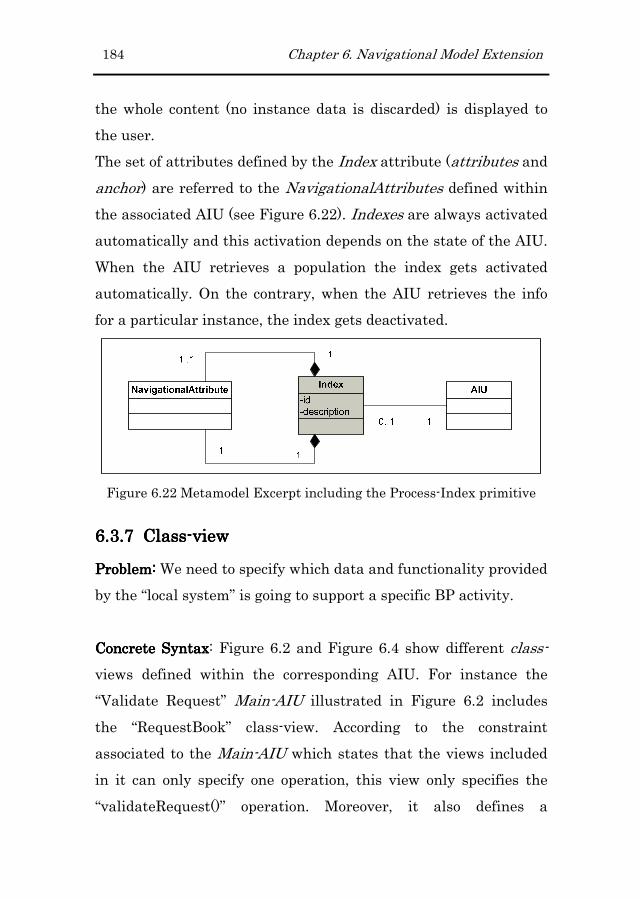
184 Chapter 6. Navigational Model Extension
the whole content (no instance data is discarded) is displayed to
the user.
The set of attributes defined by the Index attribute (attributes and
anchor) are referred to the NavigationalAttributes defined within
the associated AIU (see Figure 6.22). Indexes are always activated
automatically and this activation depends on the state of the AIU.
When the AIU retrieves a population the index gets activated
automatically. On the contrary, when the AIU retrieves the info
for a particular instance, the index gets deactivated.
Figure 6.22 Metamodel Excerpt including the Process-Index primitive
6.3.76.3.76.3.76.3.7 ClassClassClassClass----viewviewviewview
Problem: Problem: Problem: Problem: We need to specify which data and functionality provided
by the “local system” is going to support a specific BP activity.
Concrete SyntaxConcrete SyntaxConcrete SyntaxConcrete Syntax: Figure 6.2 and Figure 6.4 show different class-
views defined within the corresponding AIU. For instance the
“Validate Request” Main-AIU illustrated in Figure 6.2 includes
the “RequestBook” class-view. According to the constraint
associated to the Main-AIU which states that the views included
in it can only specify one operation, this view only specifies the
“validateRequest()” operation. Moreover, it also defines a
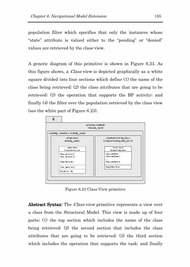
Chapter 6. Navigational Model Extension 185
population filter which specifies that only the instances whose
“state” attribute is valued either to the “pending” or “denied”
values are retrieved by the class-view.
A generic diagram of this primitive is shown in Figure 6.23. As
this figure shows, a Class-view is depicted graphically as a white
square divided into four sections which define (1) the name of the
class being retrieved; (2) the class attributes that are going to be
retrieved; (3) the operation that supports the BP activity; and
finally (4) the filter over the population retrieved by the class view
(see the white part of Figure 6.23).
Figure 6.23 Class-View primitive
Abstract Syntax:Abstract Syntax:Abstract Syntax:Abstract Syntax: The Class-view primitive represents a view over
a class from the Structural Model. This view is made up of four
parts; (1) the top section which includes the name of the class
being retrieved; (2) the second section that includes the class
attributes that are going to be retrieved; (3) the third section
which includes the operation that supports the task; and finally

186 Chapter 6. Navigational Model Extension
(4) the bottom section that defines a filter over the population
retrieved by the class view. In general, Class-views can include
several operations in their third section. However, when these are
used for BPs definition they can only include one operation
corresponding to the associated process task (when this view is
contained within a Main-AIU) or zero operations (when it is
contained within a Complementary-AIU).
Figure 6.24 Metamodel Excerpt including the NavigationalClass
primitive
Depending on the context, a Class-view can retrieve either a
particular class instance (when the class-view is passed with an
object reference) or the class population (when no object reference
is passed). Moreover, the retrieved instances have always to
satisfy the filter condition in case this has been defined.
6.3.86.3.86.3.86.3.8 ServiceServiceServiceService----DataDataDataData----viewviewviewview
Problem: Problem: Problem: Problem: We need to specify which data provided by “external
systems” is going to support a specific BP activity.

Chapter 6. Navigational Model Extension 187
Concrete SyntaxConcrete SyntaxConcrete SyntaxConcrete Syntax: Figure 6.2 shows the Service-Data-View defined
over the “CentralLibraryWS”. In this case, the Service-Data-View
retrieves the “location” and the “telephone” data from the data
returned by the “getOrganizationDetails()” operation.
A generic diagram of this primitive is shown in Figure 6.25. As
this figure shows, a Service-Data-View is depicted graphically as a
white square divided into three sections which specify (1) the
name of the service being invoked; (2) the fields that are returned
by the operation and that are going to be displayed to the user and
(3) the service operation being invoked (see the white part of
Figure 6.25).
Figure 6.25 Service-View primitive
Abstract Syntax:Abstract Syntax:Abstract Syntax:Abstract Syntax: The Service-Data-view primitive represents a
view over a service operation from the ones imported into the
Services Model.

188 Chapter 6. Navigational Model Extension
As Figure 6.26 shows, the Service-Data-view primitive has been
defined as a specialized class of the abstract ServiceView class
(class representing views over the services imported into the
Services Model).
Figure 6.26 Metamodel Excerpt including the Service-data-view
primitive
The Service-view primitive invokes a service operation and
gathers the returned values to be displayed to the user.
6.3.96.3.96.3.96.3.9 ServiceServiceServiceService----FunctionalFunctionalFunctionalFunctional----ViewViewViewView
Problem: Problem: Problem: Problem: We need to specify which functionality provided by
“external systems” is going to support a specific BP activity.
Concrete SyntaxConcrete SyntaxConcrete SyntaxConcrete Syntax: Figure 6.4 and Figure 6.27 show respectively
how service-functional-views are used in the navigational model
and how these are finally represented at the implementation level.
In particular, in Figure 6.4 the “Payment” Activity Container

Chapter 6. Navigational Model Extension 189
includes within its Main-AIU a Service-Functional-view linked to
the payment operation kept in the Services Model.
Figure 6.27 Web page corresponding to the “Payment” Activity Container
A generic diagram of this primitive is shown in Figure 6.28. As
this figure shows, a Service-Functional-View is depicted
graphically as a white square divided into two sections which
specify (1) the name of the service being invoked and (2) the
operation being invoked (see the white part of Figure 6.28).
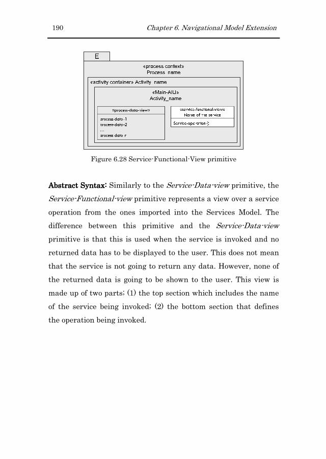
190 Chapter 6. Navigational Model Extension
Figure 6.28 Service-Functional-View primitive
Abstract Syntax: Abstract Syntax: Abstract Syntax: Abstract Syntax: Similarly to the Service-Data-view primitive, the
Service-Functional-view primitive represents a view over a service
operation from the ones imported into the Services Model. The
difference between this primitive and the Service-Data-view
primitive is that this is used when the service is invoked and no
returned data has to be displayed to the user. This does not mean
that the service is not going to return any data. However, none of
the returned data is going to be shown to the user. This view is
made up of two parts; (1) the top section which includes the name
of the service being invoked; (2) the bottom section that defines
the operation being invoked.
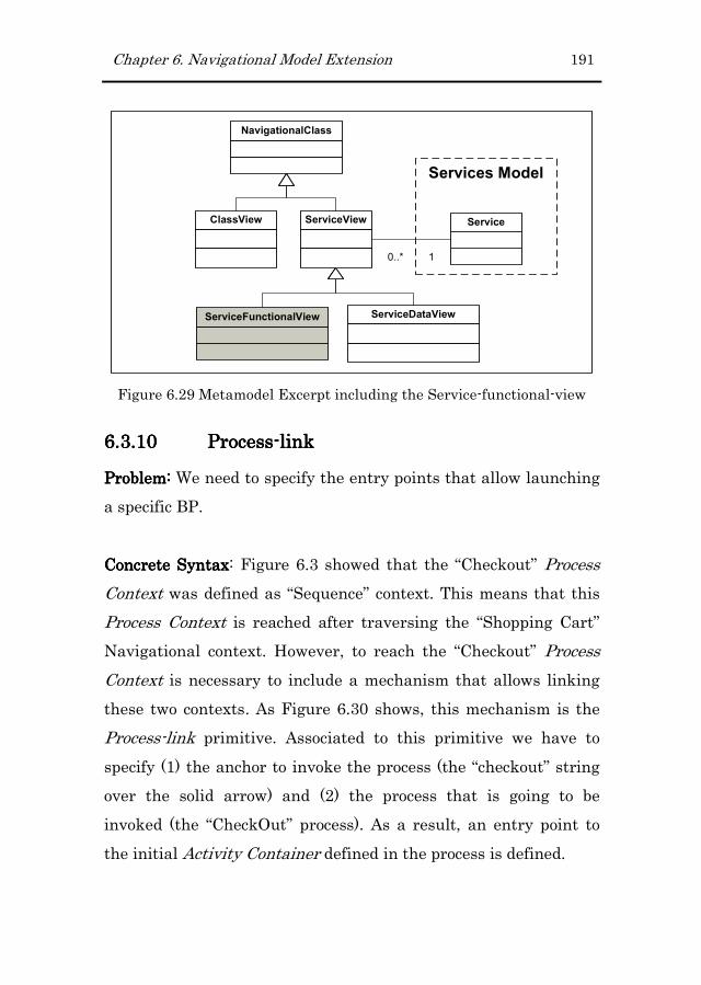
Chapter 6. Navigational Model Extension 191
NavigationalClass
Services Model
Service
0..* 1
ServiceViewClassView
ServiceDataViewServiceFunctionalView
Figure 6.29 Metamodel Excerpt including the Service-functional-view
6.3.106.3.106.3.106.3.10 ProcessProcessProcessProcess----lilililinknknknk
Problem: Problem: Problem: Problem: We need to specify the entry points that allow launching
a specific BP.
Concrete SyntaxConcrete SyntaxConcrete SyntaxConcrete Syntax: Figure 6.3 showed that the “Checkout” Process
Context was defined as “Sequence” context. This means that this
Process Context is reached after traversing the “Shopping Cart”
Navigational context. However, to reach the “Checkout” Process
Context is necessary to include a mechanism that allows linking
these two contexts. As Figure 6.30 shows, this mechanism is the
Process-link primitive. Associated to this primitive we have to
specify (1) the anchor to invoke the process (the “checkout” string
over the solid arrow) and (2) the process that is going to be
invoked (the “CheckOut” process). As a result, an entry point to
the initial Activity Container defined in the process is defined.

192 Chapter 6. Navigational Model Extension
Figure 6.30 Detail of a Navigational Context including a process-link
It is necessary to specify the activity to be invoked because the
navigational model does not define relationships between BP
activities (this is only kept by the BP handled by the process
engine). Figure 6.31 illustrates the Web page corresponding to the
“Shopping Cart” Navigational Context. In this Web page, the
entry point to the “Check Out” BP is provided by means of the
“Check Out” link included at the right hand of the Web page.
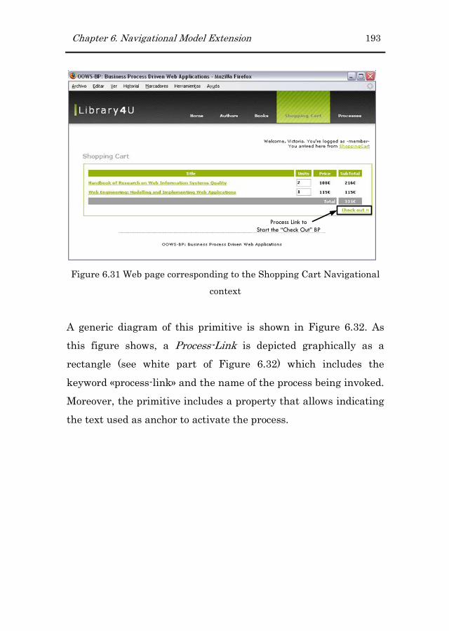
Chapter 6. Navigational Model Extension 193
Process Link to
Start the “Check Out” BP
Figure 6.31 Web page corresponding to the Shopping Cart Navigational
context
A generic diagram of this primitive is shown in Figure 6.32. As
this figure shows, a Process-Link is depicted graphically as a
rectangle (see white part of Figure 6.32) which includes the
keyword «process-link» and the name of the process being invoked.
Moreover, the primitive includes a property that allows indicating
the text used as anchor to activate the process.
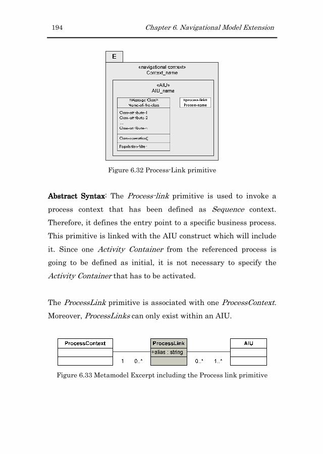
194 Chapter 6. Navigational Model Extension
Figure 6.32 Process-Link primitive
Abstract SyntaxAbstract SyntaxAbstract SyntaxAbstract Syntax: The Process-link primitive is used to invoke a
process context that has been defined as Sequence context.
Therefore, it defines the entry point to a specific business process.
This primitive is linked with the AIU construct which will include
it. Since one Activity Container from the referenced process is
going to be defined as initial, it is not necessary to specify the
Activity Container that has to be activated.
The ProcessLink primitive is associated with one ProcessContext.
Moreover, ProcessLinks can only exist within an AIU.
Figure 6.33 Metamodel Excerpt including the Process link primitive

Chapter 6. Navigational Model Extension 195
6.4 Extended Navigational Metamodel
This section presents the primitives presented in the previous
section but this time integrated with the original ones (just the
excerpt related to the former primitives is included). This
metamodel is defined as the UML class diagram presented in
Figure 6.34 together with the set of OCL constraints that have
been presented along section 6.3.
OOWS Navigational Model Excerpt
Structural Model
NavigationalNode
NavigationalContext
ProcessContext
AIU
Main-AIU
Complementary-AIU
1
11
0..*
class
1 0..*
Activity Container
1 0..*
Human-AIU
Index
ProcessLink
0..*
1..*
Base-AIUUserRole
0..1
1..*
ManagerClassComplementaryClass
NavigationalClass
11
1
0..*
1
0..*
Services Model
Service
0..* 1
0..1 1
ServiceViewClassView
Figure 6.34 Navigational Model Excerpt including the BP related
primitives
All the gray-coloured primitives depicted in Figure 6.34
correspond to the primitives related to the BP extension.

196 Chapter 6. Navigational Model Extension
6.5 Conclusions
This chapter has presented the extension defined for the OOWS
Navigational model to deal with BP integration. The presented
new primitives extend the conceptual modeling stage allowing a
correct description of web systems dealing with the execution of
BPs.
As we already stated in chapter 2, the objectives of the
navigational model are the following three ones (1) defining the
structure of the web application, (2) defining the way this
structure can be accessed and (3) defining the content and
functionality that should be provided by the web application.
However, the extension presented in this chapter only deals with
the first and third objectives of this model. The main reason to
leave out the second one is that the navigation during BP
execution is going to be driven by the process.
Moreover, apart from enriching the expressivity of the model with
new primitives, the extension enforces the relationship with other
models. In particular, new relationships with the Services Model
have been defined. This allows retrieving data and functionality
not only from our system but also from external ones.

Chapter 7
7 Presentation Model Extension
The previous chapter was dedicated to present the Navigational
extensions that are necessary to deal with the specification of BPs
in Web applications. In the current chapter we present the
extensions that are required in the Presentation model to better
adequate the Navigational contents during BP execution. Since
the Presentation model is based on a set of patterns, the extension
proposed involves the definition of new patterns that allow
improving the user experience while executing BPs. In addition, to
face the drawbacks found in existing Web engineering methods to
deal with usability issues (Atterer et al., 2006), this chapter
presents how these issues can been integrated into the OOWS
Web Engineering method to ensure the quality of the generated
web systems.
7.1 Introducing the New Presentation Primitives
Before detailing the new primitives, this section introduces them
graphically. This is performed by using the Book Purchase
Request BP. Figure 7.1 shows the presentation primitives
associated to the process context of the example.

198 Chapter 7. Presentation Model Extension
Figure 7.1 Presentation attributes associated to the Book Purchase
Request BP
As Figure 7.1 shows, the navigational elements included in the
process context have associated some presentation attributes.
These will be used during the transformation process to generate
the layout of this context accordingly.
7.2 Presentation Primitives to Support BP
execution
The extension defined over the Presentation metamodel defines
two new primitives that are associated to the GUI generated for
the execution of BPs. These new primitives correspond to the
Details On Demand and List Builder patterns. Each primitive is
going to be presented according to this schema: First, the problem
that motivates the definition of each primitive is presented.
Chapter 7. Presentation Model Extension 199
Second, the concrete syntax of the primitive is presented. This
syntax is described in a diagrammatic form and defines how the
abstract syntax (which is presented next) is presented to the end
user. Finally, the abstract syntax of the primitive is presented. In
this case, the concepts associated to the primitive and their
relationships to other primitives (even from another metamodel)
are described.
7.2.17.2.17.2.17.2.1 Details On Demand PatternDetails On Demand PatternDetails On Demand PatternDetails On Demand Pattern
Problem:Problem:Problem:Problem: The amount of data that can potentially be of interest to
users enforces developers to organize this data according to the
GUI limitations. Therefore, users have to follow different links to
reach the data that was discarded to overload the GUI. More light-
weight mechanisms are necessary to reach this discarded/ hidden
data.
Concrete Syntax:Concrete Syntax:Concrete Syntax:Concrete Syntax: According to Figure 7.1, the index associated to
the “Validate Request” Main-AIU includes a “Details On Demand”
pattern. In this case, the title attribute included in the
“RequestBook” class-view has been defined as anchor to retrieve
the information specified in the detail section of the pattern (the
editors and publisher attributes from the RequestBook class-view).
Figure 7.2 shows how this pattern is presented in a web page (web
page according to the process context depicted in Figure 7.1). In
this case, each title item defines a link with the following
behaviour: when the user positions the mouse over the title, new
contents related to the item are shown in a new floating section. In

200 Chapter 7. Presentation Model Extension
this particular case, Author, Publisher and Publish date are
shown.
Figure 7.2 Details on Demand Pattern in use
A generic diagram of this primitive is shown in Figure 7.3. As this
figure shows, a Detail On Demand pattern is applied to the index
Navigational primitive. This primitive is depicted as a white
rectangle containing two different sections. On the one hand, the
anchor section specifies which attribute is going to be used to
retrieve the “hidden” data. The available attributes for this section
corresponds to the attributes specified in the attributes section of
the index primitive. On the other hand, the detail section specifies
which data is going to be shown in the new floating widget. In this
case, the attributes included in this section are limited to the ones

Chapter 7. Presentation Model Extension 201
retrieved by the class-views and services-data-views defined
within the Main-AIU.
Figure 7.3 Detail On Demand Pattern
Abstract Syntax:Abstract Syntax:Abstract Syntax:Abstract Syntax: This pattern allows specifying how the data
contained in a Web page is shown to the user based on the user
demand. This pattern is associated to the AIU primitive and can
only include attributes from the views included in the
corresponding AIU. A complete specification of this pattern
includes an (1) anchor that could be used to retrieve the hidden
information and (2) the set of information that is going to be
displayed in the floating widget.
Figure 7.4 shows an excerpt of the Presentation metamodel
including the Details On Demand primitive. This primitive defines
a specific type of layout, and that is why this has been defined as a
subclass of the Layout primitive. In addition, we have already

202 Chapter 7. Presentation Model Extension
mentioned that this primitive can only be associated to indexes
defined within an AIU. This is shown by means of the relationship
between the Details On Demand primitive and the index primitive
defined in the Navigational Metamodel.
Figure 7.4 Metamodel Excerpt including the Details on Demand
primitive
7.2.27.2.27.2.27.2.2 List BuildList BuildList BuildList Builder Patterner Patterner Patterner Pattern
Problem:Problem:Problem:Problem: The user is presented with a list of items which
correspond to different instances of the same BP activity. In this
case, the user needs to manage this list easily and quickly.
Concrete Syntax:Concrete Syntax:Concrete Syntax:Concrete Syntax: According to Figure 7.1, the “Validate Request”
Main-AIU has been associated with the “List Builder” pattern.
The application of this pattern allows us executing the
functionality associated to the corresponding BP activity (in this
case the “validateRequest() operation) to all the instances
retrieved by the Main-AIU.
Figure 7.1 shows how this pattern is specified at the modelling
level. It can only be applied to AIU primitives. In general, this
pattern can be applied to any list whose item lines accept the same

Chapter 7. Presentation Model Extension 203
functionality. For instance, in the context of a BP execution, this
pattern can be used for completing multiple instances of the same
process task.
Figure 7.5 shows the application of this pattern to the
“ValidateRequest” Main-AIU. This pattern allows users speeding
up the completion of tasks and processes. However, this pattern
should only be used with operations requiring up to one argument.
On the contrary, the interface would get too much complex.
Figure 7.5 List Builder Pattern in use
Abstract Syntax:Abstract Syntax:Abstract Syntax:Abstract Syntax: This pattern is used to allow the user dealing
more efficiently with the data retrieved by the GUI. It allows

204 Chapter 7. Presentation Model Extension
users building up and managing a list of items at the same time.
In this case, the selected functionality can be applied on many
items at the same time.
Figure 7.6 shows an excerpt of the Presentation metamodel
including the List Builder primitive. This primitive is associated
to the Main-AIU primitive defined in the Navigational metamodel.
As the multiplicity of the composition relationships states, the
association of this pattern is optional.
Figure 7.6 Metamodel Excerpt including the List Builder primitive
7.3 Extended Presentation Metamodel
This section presents the primitives presented in the previous
section (those depicted in grey-colour) but this time integrated
with the original ones. In addition, since Presentation primitives
are defined over the primitives defined in the Navigational
metamodel, the related primitives from the Navigational model
have also been included.
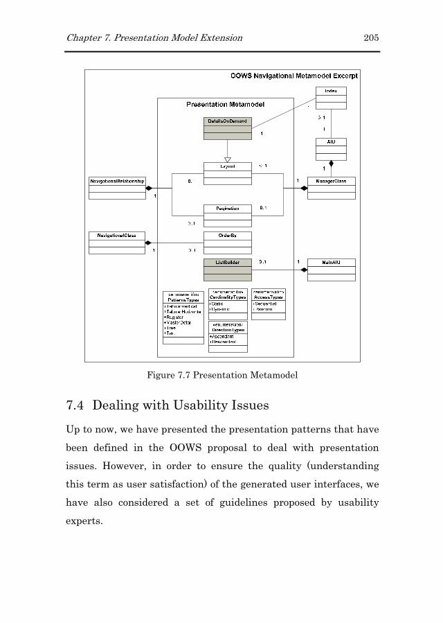
Chapter 7. Presentation Model Extension 205
Figure 7.7 Presentation Metamodel
7.4 Dealing with Usability Issues
Up to now, we have presented the presentation patterns that have
been defined in the OOWS proposal to deal with presentation
issues. However, in order to ensure the quality (understanding
this term as user satisfaction) of the generated user interfaces, we
have also considered a set of guidelines proposed by usability
experts.

206 Chapter 7. Presentation Model Extension
In most cases, the success of Web systems relies on the user
acceptance, which is associated to the user experience. In the
usability research area, the community has produced guidelines
and standards that face the different usability problems
introduced by web applications (Nielsen, 1999), (Fowler, 1998),
(van Welie), (Mayhew, 1992). However, in order to ensure that
these guidelines are used and applied properly, it is necessary to
integrate them during the software development process and
provide them with tool support (Abran et al., 2003).
If we concentrate just on the problems that can arise when
performing a business process in a web application we find that
usability guidelines are oriented to ensure that users understand
correctly the data and functionality that is shown to her.
Therefore, the usability issues that are going to face up in this
work are the following:
� Preventing Input Errors
� Notify Users when they are Expected to Perform a Task
� Displaying the Tasks Pending to Complete (Wizard
pattern)
The following subsections present how the OOWS approach cope
with these usability guidelines. The following subsections have
been organized in two parts, first we state the usability problem
being considered as well as the kind of processes in which this
usability problem applies and then we present the solution
designed in the OOWS approach to be compliance with the
corresponding guideline.

Chapter 7. Presentation Model Extension 207
7.4.17.4.17.4.17.4.1 Preventing Input ErrorsPreventing Input ErrorsPreventing Input ErrorsPreventing Input Errors
Users are required to input some data (usually by means of a web
form) and they are not provided with enough information
regarding the kind of data they are expected to input. As a result,
web forms are sent with data provided in incorrect formats and/or
unfilled fields.
This problem refers to usability guidelines gathered in (van
Welie), (Mayhew, 1992) and it can appear in both short and long-
lived processes. The guidelines provided by experts are
summarized in the following list:
� Provide right field length allowing users to see their
entered data.
� Partition long data items to aid users in detecting and
reducing entry errors.
� Minimize user data entry filling input elements providing
default values.
� Provide examples of input data that help users
understanding the information that they are asked to
input.
� Do not make mandatory fields whose data is not required
to continue the transaction.
� Use informative error messages.
Solution. These guidelines have been handled either at the
Structural Model and the Presentation Model as follows:
Class attributes and operation’s parameter defined in the
Structural Model include among other properties the followings:

208 Chapter 7. Presentation Model Extension
� Data type: It let us define the type of the attribute.
� Is mandatory: It allows specifying weather this attribute is
required to execute the operation.
� Valid value range: It let us define and control which values
can be entered.
� Default value: It lets the system suggest a predefined value
to the user. The default value is a well-formed formula that
is type-compatible with the attribute.
In the Presentation Model we associate to the Navigational
attributes included the following properties:
� Alias: It allows defining an alternative name to the
property being defined in order to present it more clearly to
the user. (Ex. An attribute whose name is tel_number and
its alias is Phone Number).
� Edit mask: It determines the format that the data shows
when the user enters it. This mask is used for several
purposes, (1) it is used to show the user an example of the
data that she is expected to input, (2) it is used to partition
long data items following the mask format and (3) it allows
to provide a correct length of the input element.
� Help message: It allows specifying a text that can be shown
to the user to provide some information about the meaning
of the data to be entered.
� Validation message: is a piece of text that is shown to the
user when a validation error occurs on the entered data.
With all this information defined at the modelling level we can
generate graphical user interfaces that satisfy the above

Chapter 7. Presentation Model Extension 209
mentioned usability guidelines and that help the user
understanding the data that she is asked to introduce.
On the other hand, other usability guidelines gathered in (Nielsen,
1999; van Welie) are better applied directly in the transformation
rules that generate the corresponding code. The main reason to
move them directly into the transformational level is that they
refer to design issues more than modeling issues. Examples of
guidelines of this type are:
� Using the most appropriate input element (radio buttons,
checkbox, list box, etc.) regarding the kind of data being
handled.
� Marking mandatory fields clearly.
� Check syntactic errors at the client side (avoiding sending
incorrect data to the server, what implies lengthening the
time dedicated to complete a task).
These three guidelines are introduced in the rules as follows:
� Appropriate widgets for input elements are generated
following the guidelines provided by Jackob Nielsen in his
Alertbox column24 in conjunction with the form pattern
defined by (van Welie). These guidelines advice the most
appropriate widget depending on the data being
represented (number of different options, exclusion,
multiple selection, etc.)
� Labels of mandatory input fields are attached with the
asterisk symbol (*).
24 http://www.useit.com/alertbox/20040927.html
210 Chapter 7. Presentation Model Extension
� Client-side scripting languages (such as JavaScript or
VBScript) or web development techniques (as AJAX25) are
generated to check syntactic errors at the client side.
7.4.27.4.27.4.27.4.2 Displaying the Tasks Pending to CompleteDisplaying the Tasks Pending to CompleteDisplaying the Tasks Pending to CompleteDisplaying the Tasks Pending to Complete
When a user starts a short-running BP it is better to display the
user with the set of steps involved in the process. This information
can be used by the user to have an idea about the information that
she has to provide in order to complete the process. On the
contrary, regarding long-running BP, the user should only be
displayed with the next pending task and not with the whole list
of tasks to complete the process. Moreover, in this case, it is not
important to provide the user with information about the steps
that she has already perform in the process.
Solution. The GUI should include (just for short-running BP) an
area that displays the sequence of tasks/steps that need to be
performed in order to complete the process. Moreover, the current
task being performed by the user must be distinguished among
the rest of the tasks. This area can be generated from the BP
definition. Figure 7.8 depicts graphically the models involved in
the transformation process to obtain the final web pages. As this
figure shows, only those activities defined in a BP that require
interaction with the user are first transformed into Activity
Containers in the Navigational Model (NM), which are later on
25 http://www.adaptivepath.com/publications/essays/archives/000385.php

Chapter 7. Presentation Model Extension 211
transformed into the web pages that will provide support to each
of those activities.
Figure 7.8 Models Used for the generation of Web Pages
The generated web pages include an area where the user can see
the list of activities that constitute the process being executed (see
group labelled as A in Figure 7.9). Moreover, the current activity
is highlighted to help the user identify clearly the current action
being performed (see group labelled as C in Figure 7.9).
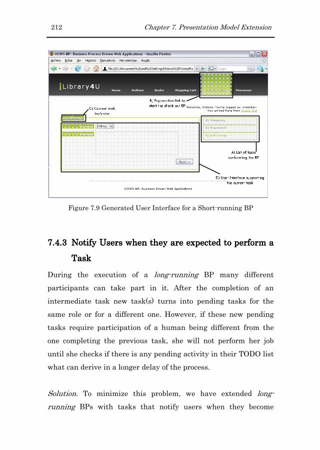
212 Chapter 7. Presentation Model Extension
Figure 7.9 Generated User Interface for a Short-running BP
7.4.37.4.37.4.37.4.3 Notify Users when they are expected to perform a Notify Users when they are expected to perform a Notify Users when they are expected to perform a Notify Users when they are expected to perform a
TaskTaskTaskTask
During the execution of a long-running BP many different
participants can take part in it. After the completion of an
intermediate task new task(s) turns into pending tasks for the
same role or for a different one. However, if these new pending
tasks require participation of a human being different from the
one completing the previous task, she will not perform her job
until she checks if there is any pending activity in their TODO list
what can derive in a longer delay of the process.
Solution. To minimize this problem, we have extended long-
running BPs with tasks that notify users when they become
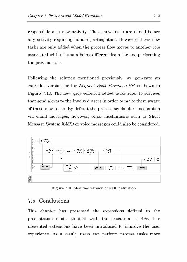
Chapter 7. Presentation Model Extension 213
responsible of a new activity. These new tasks are added before
any activity requiring human participation. However, these new
tasks are only added when the process flow moves to another role
associated with a human being different from the one performing
the previous task.
Following the solution mentioned previously, we generate an
extended version for the Request Book Purchase BP as shown in
Figure 7.10. The new grey-coloured added tasks refer to services
that send alerts to the involved users in order to make them aware
of these new tasks. By default the process sends alert mechanism
via email messages, however, other mechanisms such as Short
Message System (SMS) or voice messages could also be considered.
MEMBER
SECRETARY
CENTRAL
LIBRARY
LIBRARIAN
SYSTEM
«entity»
«role-any»
«role-any»
«role-one»
Library4U
Figure 7.10 Modified version of a BP definition
7.5 Conclusions
This chapter has presented the extensions defined to the
presentation model to deal with the execution of BPs. The
presented extensions have been introduced to improve the user
experience. As a result, users can perform process tasks more

214 Chapter 7. Presentation Model Extension
efficiently and faster. This is possible since the user is display
with useful information about the kind of task being performed
and the kind of information she is asked for. On the one hand, the
Details On Demand pattern allows the user getting more
information just in case the user really needs it. Therefore, the use
of this pattern avoid overloading user interfaces what results in
more clear interfaces. On the other hand, the List Builder pattern
allows accelerating the completion of multiple task instances.
Moreover, to improve the usability of the generated web interfaces
we have also taken into account the guidelines proposed by the
expertise community in web design. To deal with these guidelines
we have considered them, depending on its suitability, either in
the OOWS models or directly into the model to code
transformations.

Chapter 8
8 Architectural Extension
This chapter presents the extension defined at the architectural
level for Web applications to deal with the execution of Business
Processes (BPs). This extension has been designed trying to keep
the separation of concerns in which the OOWS method has been
conceived. Therefore, to keep separate the navigation that
happens during pure navigation and BP execution, we have
introduced a process engine into the architectural tier. This
element allows us obviate the navigation within the navigational
model since this is going to be fully controlled by the process. As a
result, a more clear and easy to handle navigational model is built
for BP execution. In addition, as a consequence of introducing a
process engine into the architecture, process definitions have to be
defined in a process executable language. In particular, in this
work we have chosen the WS-BPEL language. This language
allows specifying BPs behaviour based exclusively on Web
Services. This limitation forced us to introduce new elements into
the business layer to handle the lack of WS-BPEL for supporting
human tasks.
216 Chapter 8. Architectural Extension
8.1 Introduction
Similar to the introduction of database management systems into
the architecture of software systems, dealing with systems that
support the execution of Business Processes (BPs) requires the
introduction of solutions that allow us handling BPs properly.
These solutions provide mechanisms to model, automate,
integrate, monitor and optimize BPs continuously (Hollingsworth,
1995). From this set of mechanisms, the one we are interested of
at this point is the one related with the automation of BPs. This
automation is achieved by the use of a process engine which
launches and run instances of existing BPs.
Based on the decision of adopting WS-BPEL as the executable
language of processes (see chapter 2), we have introduced into the
architecture of the generated Web applications a process engine
that implements this specification. In particular, we have made
use of the ActiveBPEL26 process engine.
However, as WS-BPEL is based on Web services, when we want to
model workflows (processes that include human participants) we
have to make use of some mechanisms on top of the original
specification to allow us handling the asynchrony introduced by
this kind of process participants27.
26 http://www.active-endpoints.com/active-bpel-engine-overview.htm
27 Trying to face this limitation, the WS-BPEL Extension for People
(Kloppmann et al., 2005) has been proposed.

Chapter 8. Architectural Extension 217
This chapter presents the extension defined at the architectural
level in order to cope properly with the requirements of the kind of
Web applications that we are dealing with.
8.2 Extension Overview
In this section we present the whole picture of the architecture of
the kind of Web applications we are dealing with. As Figure 8.1
shows, the architecture follows the classical 3-Tier architecture. In
this architecture each layer interacts only with the layers placed
immediately next to it and is responsible for a specific function.
From these three layers, we are going to focus on the Business
layer, layer where the presented extension has been placed.
Figure 8.1 Three Layer architecture for Process-driven Web applications
In order to keep the separation of concerns established by this
three-architecture tier, the Model-View-Controller (MVC)
architectural pattern (Reenskaug, 1979; Reenskaug, 2003) is the
most appropriate solution to be applied. Each part of the pattern

218 Chapter 8. Architectural Extension
is in charge of a specific task, ModelsModelsModelsModels are used to maintain data,
ViewsViewsViewsViews are used for displaying all or part of the data and finally
ControllersControllersControllersControllers are used for handling events that affect the model or
view(s). The major benefits of this separation of concerns are (1)
the reduction of the complexity of the architectural design and (2)
the increase of flexibility and reuse. On the one hand, complexity
is reduced since the controller part decouples data access and
business logic from data presentation and user interaction. On the
other hand, the increase of flexibility and reuse is achieved by the
possibility of defining multiple views for the same model
depending on the target user.
In this work, the proposed architecture has been mapped to the
Tapestry Web Framework28. In this framework, the different parts
of the MVC pattern are represented by different types of files as
Figure 8.2 shows.
Figure 8.2 Tapestry File Organization
28 http://tapestry.apache.org/
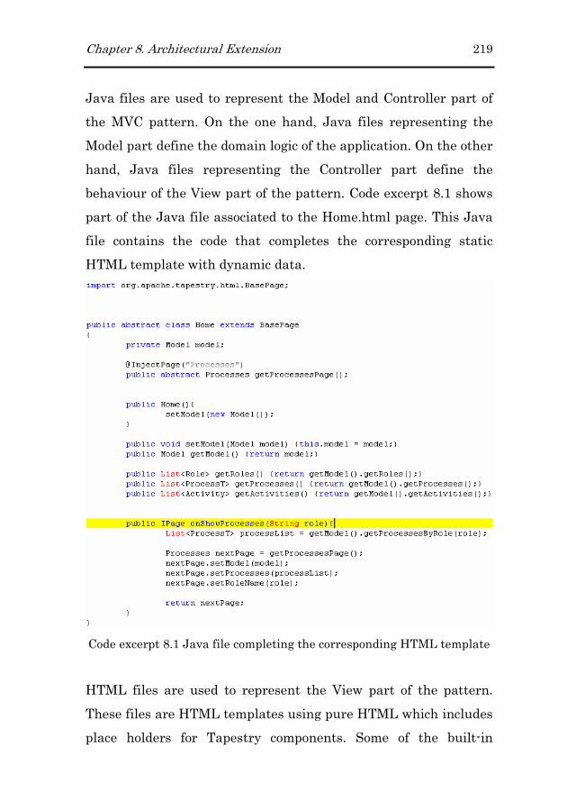
Chapter 8. Architectural Extension 219
Java files are used to represent the Model and Controller part of
the MVC pattern. On the one hand, Java files representing the
Model part define the domain logic of the application. On the other
hand, Java files representing the Controller part define the
behaviour of the View part of the pattern. Code excerpt 8.1 shows
part of the Java file associated to the Home.html page. This Java
file contains the code that completes the corresponding static
HTML template with dynamic data.
Code excerpt 8.1 Java file completing the corresponding HTML template
HTML files are used to represent the View part of the pattern.
These files are HTML templates using pure HTML which includes
place holders for Tapestry components. Some of the built-in

220 Chapter 8. Architectural Extension
Tapestry components are For (to loop over a collection of source
values), Insert (to allow for the insertion of text into the HTML
response), DirectLink (to create an <a> hyperlink that notifies the
component when the link is triggered) or Submit (to provide an
HTML form submission element). Code excerpt 8.2 shows the
HTML template built for the Home page. Within the HTML code
and associated to the span tag we find the “jwcid” special attribute
which references to a Tapestry component.
Code excerpt 8.2 HTML Template
Page files are XML descriptor files that allow combining HTML
templates with Java code. These files are optional but they
contribute to have a more legible code. Code excerpt 8.3 shows the
XML included in the Home.page descriptor. This file links HTML
templates with the associated Java files.

Chapter 8. Architectural Extension 221
Code excerpt 8.3 XML Descriptor
8.2.18.2.18.2.18.2.1 Presentation LayerPresentation LayerPresentation LayerPresentation Layer
The Presentation Layer is the layer responsible for (1) providing
an interface for the end users into our application and (2) for
exposing business functionality to external partners by means of
Web services. In Web applications, for the generation of graphical
user interfaces, this layer includes dynamic web pages which are
created by server-side languages such as ASP, JSP, PERL, or PHP
among others. On the other hand, the business logic exposed to
external partners is provided by means of Web services.

222 Chapter 8. Architectural Extension
8.2.28.2.28.2.28.2.2 Business TierBusiness TierBusiness TierBusiness Tier
This tier communicates with the presentation layer and the data
layer and depending on the case, its responsibility changes. On the
one hand, the Business Tier is responsible for accessing the data
tier to process (retrieve, modify and delete) data to and from the
data tier. On the other hand, it is responsible for sending the
results to the presentation tier.
The extension proposed in this chapter involves this tier. This
extension includes two new elements which are the Process Process Process Process
EngineEngineEngineEngine and the Task Manager Task Manager Task Manager Task Manager Web Web Web Web ServiceServiceServiceService. The function of the
PPPProcess rocess rocess rocess EEEEnginenginenginengine is creating and running new process instances
from input WS-BPEL processes when an incoming message
triggers the start process activity. Moreover, since WS-BPEL is
based on Web services, and these can be hosted on different
servers, the business tier can be distributed being their
components linked by the process engine. The Task ManagerTask ManagerTask ManagerTask Manager WebWebWebWeb
ServiceServiceServiceService (see Figure 8.3) is the element that comes into play when
activities related to humans are invoked. This service takes the
responsibility of handling this kind of activities, and
communicates with the process engine and the application logic (a
detailed explanation is provided later on in the chapter).
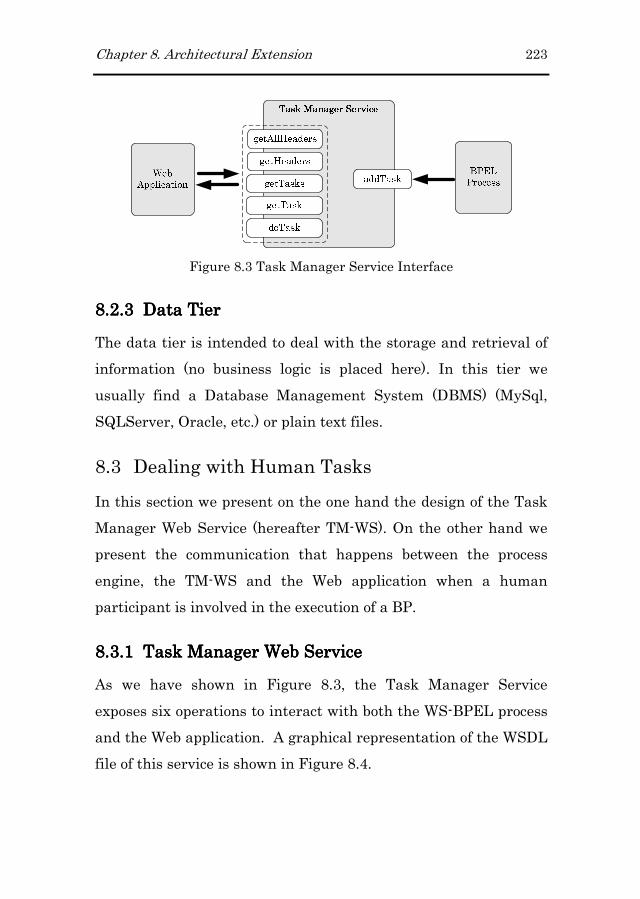
Chapter 8. Architectural Extension 223
Figure 8.3 Task Manager Service Interface
8.2.38.2.38.2.38.2.3 Data TierData TierData TierData Tier
The data tier is intended to deal with the storage and retrieval of
information (no business logic is placed here). In this tier we
usually find a Database Management System (DBMS) (MySql,
SQLServer, Oracle, etc.) or plain text files.
8.3 Dealing with Human Tasks
In this section we present on the one hand the design of the Task
Manager Web Service (hereafter TM-WS). On the other hand we
present the communication that happens between the process
engine, the TM-WS and the Web application when a human
participant is involved in the execution of a BP.
8.3.18.3.18.3.18.3.1 Task Manager WeTask Manager WeTask Manager WeTask Manager Web Serviceb Serviceb Serviceb Service
As we have shown in Figure 8.3, the Task Manager Service
exposes six operations to interact with both the WS-BPEL process
and the Web application. A graphical representation of the WSDL
file of this service is shown in Figure 8.4.

224 Chapter 8. Architectural Extension
Figure 8.4 WSDL for the Task Manager Service
The interface of the TM-WS defines all these operations based on
the way in which this has been implemented. To understand
better these operations it is necessary first to explain how tasks
are handled by this service. In Figure 8.5 we show the class model
design to handle tasks. The TaskManager class handles zero or
multiple tasks (relationship defined between this class and the
Task class). Then, a task is defined by a header (composition
relationship between the Task and Header classes) and a payload
(document). On the one hand, the header includes information
such as the identifier of the task, the user involved, the user group
and the name of the process and the task. On the other hand, the
payload is a XML file containing the data of the task.

Chapter 8. Architectural Extension 225
Figure 8.5 Task Manager Structure
Then, the operations published by the Task Manager are the
following:
� “getAllHeadersgetAllHeadersgetAllHeadersgetAllHeaders” and “getHeadersgetHeadersgetHeadersgetHeaders” operations have been
defined to access more efficiently to the information about
the tasks kept by the Task manager. These operations will
be invoked to build dynamically the menu that allows users
to access their pending tasks. “getHeadersgetHeadersgetHeadersgetHeaders” accepts a query
that allows specifying which tasks we are interested in (i.e.
pending tasks for a particular user or for a group of users).
The following Code excerpt 8.4 shows how the “getHeadersgetHeadersgetHeadersgetHeaders”
operation is invoked by a particular function designed to
see if there are pending activities for a specific process.
public boolean getActivityPending(){
String activityName = getCurrentActivity().getName();
if(activityName.equals("Request a Book Purchase")){
return true;
}
Header h = new Header(); //This header will be the query
h.setTaskName(activityName);
Collection<Header> list = service.getHeaders(h);
//If there are pending tasks the current activity will be a link
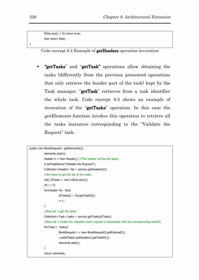
226 Chapter 8. Architectural Extension
if(list.size() > 0) return true;
else return false;
}
Code excerpt 8.4 Example of getHeadersgetHeadersgetHeadersgetHeaders operation invocation
� ““““getTaskgetTaskgetTaskgetTaskssss” and “getTask” getTask” getTask” getTask” operations allow obtaining the
tasks (differently from the previous presented operations
that only retrieve the header part of the task) kept by the
Task manager. “getTaskgetTaskgetTaskgetTask” retrieves from a task identifier
the whole task. Code excerpt 8.5 shows an example of
invocation of the “getTasksgetTasksgetTasksgetTasks” operation. In this case the
getElements function invokes this operation to retrieve all
the tasks instances corresponding to the “Validate the
Request” task.
public List<BookRequest> getElements(){
elements.clear();
Header h = new Header(); //This header will be the query
h.setTaskName("Validate the Request");
Collection<Header> list = service.getHeaders(h);
//We have to get the ids of the tasks
int[] idTasks = new int[list.size()];
int i = 0;
for(Header hd : list){
idTasks[i] = hd.getTaskID();
i++;
}
//Now let´s get the tasks
Collection<Task> tasks = service.getTasks(idTasks);
//Now let´s create the requests (each request is associated with the corresponding taskID)
for(Task t : tasks){
BookRequest r = new BookRequest(t.getPayload());
r.setIdTask(t.getHeader().getTaskID());
elements.add(r);
}
return elements;

Chapter 8. Architectural Extension 227
}
Code excerpt 8.5 Example of getTasksgetTasksgetTasksgetTasks operation invocation
� “doTaskdoTaskdoTaskdoTask” is the operation invoked by the application to
notify the TM-WS for erasing the task whose identifier
coincides with the one passed to the operation. The
following code excerpt includes part of the generated Web
application code where the “doTask” operation is invoked.
public void onFormSubmit(){
BookRequest r = new BookRequest();
for(BookRequest x : elements){
if(x.getIdTask() == getTaskID()) r=x;
}
r.validate(r.isValid());
Document requestxml = r.serialize("Validate_the_Request");
try{
//Send the request to the external service and remove task from the taskManager
SoapClient.sendRequest(humanService, requestxml);
service.doTask(getTaskID());
}catch(SOAPException e){;
}catch(IOException e){;}
}
Code excerpt 8.6 Example of doTadoTadoTadoTasksksksk operation invocation
� “addTaskaddTaskaddTaskaddTask” is the operation invoked by the WS-BPEL
process when a task involving human participation is
reached by the process flow. As parameter, the operation
accepts the identifier of the process instance. The reason
for requiring this identifier is to perform the correlation
between process instances and data. Code excerpt 8.7
shows WS-BPEL portion where the “addTask” operation is
invoked.
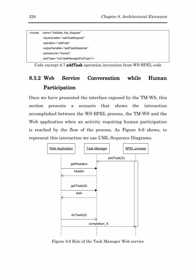
228 Chapter 8. Architectural Extension
<invoke name="Validate_the_Request"
inputVariable="addTaskRequest"
operation="addTask"
outputVariable="addTaskResponse"
partnerLink="human"
portType="ns3:taskManagerPortType"/>
Code excerpt 8.7 addTaskaddTaskaddTaskaddTask operation invocation from WS-BPEL code
8.3.28.3.28.3.28.3.2 Web Service Web Service Web Service Web Service Conversation while Human Conversation while Human Conversation while Human Conversation while Human
ParticipationParticipationParticipationParticipation
Once we have presented the interface exposed by the TM-WS, this
section presents a scenario that shows the interaction
accomplished between the WS-BPEL process, the TM-WS and the
Web application when an activity requiring human participation
is reached by the flow of the process. As Figure 8.6 shows, to
represent this interaction we use UML Sequence Diagrams.
Web Application Task Manager BPEL process
getHeaders
header
getTask(id)
task
addTask(X)
completion_X
doTask(id)
Figure 8.6 Role of the Task Manager Web service

Chapter 8. Architectural Extension 229
The invocation sequence is the following:
• First of all, the process engine starts running a BP (either
short-running or long-running process) which includes some
activities involving human participation (i.e. approve
purchase, review code, etc). Then, when one of these activities
is reached by the flow of the process, the WS-BPEL process
sends a request to the TM-WS to handle it. This interaction is
represented in Figure 8.6 by the asynchronous call invoking
the “addTask” operation.
• Then, the TM-WS creates a work item to represent the
request. Moreover, it stores correlation information so that a
subsequent request to the WS-BPEL process can locate the
originating process instance.
• The Web application, when a user logs into the system,
contacts the TM-WS to reach the set of pending tasks for the
logged user. At this point, the user is responsible for
completing the work item, which is accomplished through the
corresponding user interface from the Web application. The
completion of the work triggers two calls. One the one hand,
the “doTask” operation is invoked to notify the TM-WS that
this task has been completed and can be removed from the
Task manager. On the other hand, the “completion_X”
operation is invoked to pass back the control to the WS-BPEL
process (the “X” references the name of the task which
coincides with the string passed as argument to the “addTask”
operation). This operation is sent together with correlation
230 Chapter 8. Architectural Extension
information to inform the process engine about the completion
of the task for a particular process instance.
8.4 Conclusions
This chapter has presented the extension performed to the
architecture of the generated web applications in order to handle
properly the execution of business processes. This extension
involves on the one hand the introduction, at the business layer, of
a process engine capable of handling BP instances. On the other
hand, in order to cope with the lack of WS-BPEL to support
processes involving human participants, we have defined a new
service (the Task Manager Web Service) which handles this kind
of tasks.
An important issue that we have taken into account is the
portability of the provided solution. It was a must to keep WS-
BPEL process definitions independent of any process engine
vendor. For this reason, the Task Manager Web Service has been
defined as an external partner for the WS-BPEL process, similar
to any other external partner. For instance, instance process
correlation is achieved by means of identifiers generated by the
“objects” handled in the own process instance. This decision allows
us controlling correlation in the same way independently of the
engine used.

Chapter 9
9 Model Transformations
In previous chapters we have presented the necessary concepts for
creating the models that allow represent properly BP-driven Web
applications. However, to get the most from a Model Driven
Development (MDD) approach as the one presented in this thesis,
it is necessary to automate the transformations that allow
translating models to other artefacts, including code. Depending
on the type of generated artefact, a model-to-model (M2M) or
model-to-text (M2T) transformation has been defined. Therefore,
this chapter presents the set of transformations that implement
the mappings between the models defined in the proposal and
other artefacts such as models and code.
The chapter has been structured as follows. First of all, section 9.1
provides an overview of the M2M and M2T transformations
defined along the development process. These transformations
generate two different types of artefacts, which are an executable
WS-BPEL process and a Web application. Then, according to the
different generated artefacts, sections 9.2 and 9.3 present in detail

232 Chapter 9. Model Transformations
the transformations implemented in each case. Finally, section 9.4
presents the conclusions of this chapter.
9.1 The Big Picture
Following the Model Driven Development (MDD) approach, we
have defined and implemented a set of model transformations to
obtain a complete Web application according to the architecture
presented in chapter 8. These transformations are dedicated to
obtain (1) the WS-BPEL definition of the BPs modelled in the
Business Process Model (BPM) and (2) the Web application that
gives support to these BPs in a specific Web framework (the
Tapestry Web Framework). Figure 9.1 and Figure 9.2 present
graphically the set of steps that are necessary to obtain in each
case the required artefacts. The numbers included in both figures
define the order in which these transformations are performed.
Figure 9.1 Transformations Defined for generating the WS-BPEL code
On the one hand, Figure 9.1 details the steps that have been
defined to obtain, from a BP specification represented using the
BPMN notation, an executable BP represented in the WS-BPEL
language. The transformation process includes M2M and M2T
transformations. In addition, the BPMN2BPEL Babel tool has

Chapter 9. Model Transformations 233
been used to generate part of the WS-BPEL document. As this
figure shows, this document is obtained not only from the BPM. It
also requires the Structural and Services Models which are used
to complete some of the WS-BPEL sections.
Figure 9.2 Transformations Defined for generating the Web site for the
Tapestry Framework
On the other hand, Figure 9.2 details the steps that have been
defined to obtain the Web application that supports the BPs
specified in the BPM. Specifically, this application is generated for
the Tapestry Web Framework. For this reason, according to the
architecture imposed by this framework, these transformations
produce a set of .java, .page and .html files.
Although model transformation is a relatively young area, there
already exist different possibilities to perform this task (Czarnecki
& Helsen, 2003). Specifically, the options that have been taken to
implement the transformations defined in this work are the Atlas
Transformation Language (ATL29) to implement M2M
transformations and MOFScript30 to implement M2T
transformations. A key factor on the selection of the
29 http://www.eclipse.org/m2m/atl/
30 http://www.eclipse.org/gmt/mofscript/
234 Chapter 9. Model Transformations
transformation languages was their tool support in order to apply
the proposal in practice. The usage of Eclipse-based tools could
permit seamless tool integration with other projects used by the
present work such as Eclipse Modelling Project31 and SOA Tools
Platform Project32.
The ATL language (Jouault & Kurtev, 2006) is a proposal
developed in parallel to the OMG QVT (OMG, 2005a) standard for
model transformation (Miller & Mukerji, 2003). ATL is a hybrid
language (declarative and imperative) that allows the definition of
rules that describe how source model elements are matched and
navigated to create and initialize the elements of the target
models. Moreover, it provides an IDE developed on top of the
Eclipse platform, which provides a number of standard
development tools providing support to the edition, execution and
debugging of M2M transformations.
With regard to M2T transformations, MOFScript was one of the
candidates in the OMG RFP process on MOF Model to Text
Transformation. It is included in an Eclipse subproject aimed at
developing tools and frameworks for supporting model to text
transformations, e.g., to support generation of implementation
code or documentation from models. Some of the characteristics
that made this tool a good candidate to deal with M2T
transformations were that (1) it allows generating text from MOF-
31 http://www.eclipse.org/modeling/
32 http://www.eclipse.org/stp/

Chapter 9. Model Transformations 235
based models, (2) it defines a set of mechanisms that facilitates
the implementation of transformations (i.e., control mechanisms,
string manipulation, expressions to reference model elements), (3)
it allows specifying the file being generated and (4) it allows keep
traceability between source models and generated files.
9.2 Model Transformations to Generate WS-BPEL
code
The main goal of the BPMN notation is bridging the gap between
the business process design and the process implementation. The
way to bridge this gap has already been documented (White, 2005)
and even implemented in some tools (Borland Together33 or Oracle
BPEL Manager34). With regard to the published documentation,
this is based on a particular example and does not provide a
complete mapping between BPMN diagrams and WS-BPEL. On
the other hand, the limitations of WS-BPEL forces extending the
language in proprietary ways, which works against the language
promised portability. If the required extension were based on Web
services interfaces, the portability would not be compromised.
However, most vendors add proprietary extensions to lock users in
their products.
Therefore, we needed to provide a transformation that (1) would
cover the whole mapping between the graphical notation and the
33 http://www.borland.com/us/products/together/index.html
34 http://www.oracle.com/technology/bpel/index.html

236 Chapter 9. Model Transformations
executable language and (2) would generate an executable
representation 100% compliant with the standard. In this
direction, we found within the Babel project35 developed by the
Business Process Management Group36 the BPMN2BPEL37 tool.
This tool is a Java application that transforms process models
represented in BPMN diagrams into process definitions
represented in WS-BPEL (Ouyang et al., 2006). This tool seems
initially promising but it has some limitations:
1. It does not include a graphical editor for BPMN modelling.
Although providing graphical editors to build models is not
a must for the realization of the MDD approach, it
constitutes in most cases the key factor for the success of
any tool.
2. The generated WS-BPEL code is incomplete and only
generates the code related to activities within a WS-BPEL
document. The completeness of a WS-BPEL document is
necessary in order deploy successfully the process
definition into a process engine.
As can be seen in Figure 9.1, the WS-BPEL complete code
generation process has been defined using both M2M and M2T
transformations and includes the following steps:
35 http://www.bpm.fit.qut.edu.au/projects/babel/
36 http://www.bpm.fit.qut.edu.au/
37 http://www.bpm.fit.qut.edu.au/projects/babel/tools/

Chapter 9. Model Transformations 237
1. First of all, BP definitions depicted graphically following
the BPMN notation are transformed into BPs according
the Babel tool format.
2. In parallel to the first step we can generate the interface
(WSDL file) of the WS-BPEL process as well as the data
types used by it. The interface is generated in the WSDL
language since the executable WS-BPEL process is seen
from the outside as a Web service.
3. Once we have a business process representation according
to the schema defined by the Babel tool we can execute the
BPMN2BPEL tool to obtain a preliminary version of the
WS-BPEL document.
4. Finally, the previously obtained WS-BPEL document is
completed by including the sections that are not built by
the Babel tool (which are the partner link, variables and
correlation set sections) and by associating activities with
the proper partner. Moreover, before sending and receiving
data to and from an external partner it is necessary to
perform a transformation process to map the data types
used by the process to the ones used by the external
partners. Therefore, it is necessary (1) to build a new
partner in charge of this transformation process and (2) to
include the activities that invoke the operations providing
this functionality.
After the application of this set of steps we obtain a complete
executable WS-BPEL document which can be executed in a WS-

238 Chapter 9. Model Transformations
BPEL engine. The following subsections present in detail each of
these steps.
9.2.19.2.19.2.19.2.1 From the BPM to BPMN according to the Babel From the BPM to BPMN according to the Babel From the BPM to BPMN according to the Babel From the BPM to BPMN according to the Babel
ToolToolToolTool
In the context of M2M transformations, we have defined and
implemented the necessary transformation rules to overcome the
BPMN modelling limitation of the BPMN2BPEL tool. Since the
metamodel used by the Babel tool is quite simple (considering just
tasks, links and gateways to control the flow) the set of
transformations defined in this case are quite straight forward as
the following list shows:
� Activities are transformed into nodes (see Code excerpt 9.1)
� Links, which connect two nodes, are transformed into arcs
(see Code excerpt 9.2)
rule Activity2Node{ from a: bpmn!Activity(a.isLocal and (not a.isHuman) and (not a.isSend) and (not a.isReceive) and (not a.isStartEvent)) to node: babel!Node( id<-a.iD, name<- a.name, type <- a.nodeType ) }
Code excerpt 9.1 Rule transforming Activities into nodes
rule Sequence2Arc{ from s: bpmn!SequenceEdge(s.isLocal and not s.target.isInitial) to arc: babel!Arc( id<-s.iD, source<- if s.source.isHuman and (not s.source.isInitial) then thisModule.Human2Complete(s.source).id else

Chapter 9. Model Transformations 239
if s.source.isReceive then thisModule.Activity2Transform(s.source).id else s.source.iD endif endif, target<- if s.target.isSend then thisModule.Activity2Transform(s.target).id else s.target.iD endif, guard<-s.name ) }
Code excerpt 9.2 Rule transforming Links into arcs
In addition to these two transformation rules, a set of additional
helpers functions have been defined in order to inquire some
properties about elements of the model. This is necessary since
BPMN considers more activity types than the ones supported by
the Babel format. Therefore, these helpers constitute the
mappings between the BPMN and the Babel activity types. In the
Code excerpt 9.3 the helper defining the mappings between the
whole set of BPMN start events and the one supported by Babel is
presented.
helper context bpmn!Activity def: isStartEvent:Boolean=
let types: Sequence(bpmn!ActivityType)=
Sequence{#EventStartEmpty,
#EventStartMessage,
#EventStartRule,
#EventStartTimer,
#EventStartLink,
#EventStartMultiple} in
types->includes(self.activityType);
Code excerpt 9.3 Helper to check whether an activity is defined as a start
activity

240 Chapter 9. Model Transformations
A set of helpers have been defined to determine the type of the
activity being handled (isStartEvent, isMessageEvent,
isTimerEvent, isXorJoin, isXorSplit, isEbXorJoin, isEbXorSplit,
isAndJoin, isAndSplit, isEndEvent, isTask, nodeType). For the
complete definition of these helpers see Appendix D38.
However, as we have already mentioned, the WS-BPEL document
generated by the Babel tool constitutes a preliminary version of
the document. The code presented in the Code excerpt 9.4 shows
the WS-BPEL document generated for the “Request Book
Purchase” process (see Appendix C) by the Babel tool.
<?xml version="1.0" encoding="UTF-8"?>
<process xmlns="http://schemas.xmlsoap.org/ws/2003/03/business-process/"
name="output.babel" targetNamespace="http://samples.org/output.babel">
<!--bpmn2bpel Version 1.0-->
<partnerLinks>
<!--List of services participating in this BPEL process-->
<partnerLink name="local" partnerLinkType="localPT" myRole="localService" />
</partnerLinks>
<variables>
<!--List variables used in this BPEL process-->
</variables>
<sequence name="sequenceComponent_6">
<receive name="ProcessInstantiation" partnerLink="client"
portType="localPT" operation="localPT" variable="client_data"
createInstance="yes" />
<sequence name="sequenceComponent_1">
38 Available on-line at
http://www.dsic.upv.es/~vtorres/thesis/appendixes/appendixD

Chapter 9. Model Transformations 241
<invoke name="RequestaBookPurchase" partnerLink="local"
portType="localPT" operation="RequestaBookPurchase"
inputVariable="RequestaBookPurchase_data_in"
outputVariable="RequestaBookPurchase_data_out" />
<invoke name="ValidatetheRequest" partnerLink="local" portType="localPT"
operation="ValidatetheRequest"
inputVariable="ValidatetheRequest_data_in"
outputVariable="ValidatetheRequest_data_out" />
<receive name="complete_ValidatetheRequest" partnerLink="local" portType="localPT"
operation="completion_complete_ValidatetheRequest"
variable="complete_ValidatetheRequest_data" createInstance="no" />
</sequence>
<switch>
<case condition="no">
<invoke name="NotifyRequestRejection" partnerLink="local" portType="localPT"
operation="NotifyRequestRejection"
inputVariable="NotifyRequestRejection_data_in"
outputVariable="NotifyRequestRejection_data_out" />
</case>
<case condition="yes">
<sequence name="sequenceComponent_4">
<sequence name="sequenceComponent_2">
<invoke name="transform_SendRequest" partnerLink="local" portType="localPT"
operation="transform_SendRequest"
inputVariable="transform_SendRequest_data_in"
outputVariable="transform_SendRequest_data_out" />
<invoke name="SendRequest" partnerLink="local" portType="localPT"
operation="SendRequest"
inputVariable="SendRequest_data_in"
outputVariable="SendRequest_data_out" />
<receive name="ReceivePurchaseNotification" partnerLink="local" portType="localPT"
operation="completion_ReceivePurchaseNotification"
variable="ReceivePurchaseNotification_data" createInstance="no" />
<invoke name="transform_ReceivePurchaseNotification" partnerLink="local"
portType="localPT"
operation="transform_ReceivePurchaseNotification"
inputVariable="transform_ReceivePurchaseNotification_data_in"
outputVariable="transform_ReceivePurchaseNotification_data_out" />
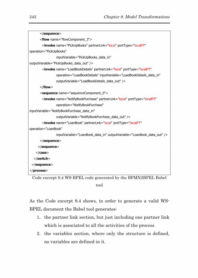
242 Chapter 9. Model Transformations
</sequence>
<flow name="flowComponent_3">
<invoke name="PickUpBooks" partnerLink="local" portType="localPT"
operation="PickUpBooks"
inputVariable="PickUpBooks_data_in"
outputVariable="PickUpBooks_data_out" />
<invoke name="LoadBookDetails" partnerLink="local" portType="localPT"
operation="LoadBookDetails" inputVariable="LoadBookDetails_data_in"
outputVariable="LoadBookDetails_data_out" />
</flow>
<sequence name="sequenceComponent_0">
<invoke name="NotifyBookPurchase" partnerLink="local" portType="localPT"
operation="NotifyBookPurchase"
inputVariable="NotifyBookPurchase_data_in"
outputVariable="NotifyBookPurchase_data_out" />
<invoke name="LoanBook" partnerLink="local" portType="localPT"
operation="LoanBook"
inputVariable="LoanBook_data_in" outputVariable="LoanBook_data_out" />
</sequence>
</sequence>
</case>
</switch>
</sequence>
</process>
Code excerpt 9.4 WS-BPEL code generated by the BPMN2BPEL Babel
tool
As the Code excerpt 9.4 shows, in order to generate a valid WS-
BPEL document the Babel tool generates:
1. the partner link section, but just including one partner link
which is associated to all the activities of the process
2. the variables section, where only the structure is defined,
no variables are defined in it.
Chapter 9. Model Transformations 243
Finally, regarding the Correlation Set section, not even the
structure is built. This limitation of the Babel tool is due to the
lack of expressivity of the metamodel handled by it. In fact, this
metamodel is only composed of two primitives which are nodes
and arcs (the whole metamodel is shown in Appendix D39).
Therefore, it is necessary to add the information that cannot be
generated by the Babel tool.
9.2.29.2.29.2.29.2.2 Completing the WSCompleting the WSCompleting the WSCompleting the WS----BPEL DocumentBPEL DocumentBPEL DocumentBPEL Document
The following subsections explain the transformations defined to
complete the WS-BPEL document generated by the Babel tool.
These explanations are accompanied with some interesting code
excerpts which are also presented in appendixes40 D, E and F.
Adding the Partner Link Adding the Partner Link Adding the Partner Link Adding the Partner Link and Namespace and Namespace and Namespace and Namespace sectionsectionsectionsectionssss
The first section that we are going to focus on is the section related
to the partners interacting with the process. Before going deep
into the details, Figure 9.3 depicts graphically the interaction
schema that is going to be used for each generated WS-BPEL
document.
39 Available on-line at
http://www.dsic.upv.es/~vtorres/thesis/appendixes/appendixD
40 Available on-line at http://www.dsic.upv.es/~vtorres/thesis/appendixes

244 Chapter 9. Model Transformations
Figure 9.3 Interaction between the WS-BPEL process and the set of
Partners
As Figure 9.3 shows the WS-BPEL process interacts with four
different types of Web services which are the Task Manager WS,
the System WS, the Transformer WS and the collection of Partner-
i WS.
1. The Task Manager Web serviceTask Manager Web serviceTask Manager Web serviceTask Manager Web service has been defined to
overcome the WS-BPEL lack for handling human tasks. If
the WS-BPEL process includes tasks involving human
participation, this service must be always present as a
partner. This service provides a set of operations that are
invoked when a task demanding human participation is
reached by the process flow (see chapter 8 for a detailed
description of this service).
2. The System Web serviceSystem Web serviceSystem Web serviceSystem Web service is the partner in charge of
providing all the functionality defined in the local system
and that is associated with process activities. Therefore,

Chapter 9. Model Transformations 245
this service will only be generated when the WS-BPEL
process invokes functionality defined in the local system.
3. The Transformer Web serviceTransformer Web serviceTransformer Web serviceTransformer Web service is a service in charge of
performing format conversions between the data types used
by the WS-BPEL service and the data types used by each of
the business partners. This service is, by the moment, built
manually. However, based on works such as (Benatallah et
al., 2005) where adapters are defined automatically to
integrated different Web services, this service would be
built automatically.
4. Finally, the set of PartnerPartnerPartnerPartner----i Web servicei Web servicei Web servicei Web services s s s represent each
one of the external business partners involved in the
process. There is one per each business partner.
The Code excerpt 9.5 shows the ATL code defined for the
construction of the four types of partners interacting with the WS-
BPEL process. This code can be found in Appendix D.
helper context bpmn!BpmnDiagram def: partnerLinks:Sequence(TupleType(name:String, type:String,myRole:String,partnerRole:String))= let procName:String=self.name.normalize in let ns:String='ns1' in Sequence{ Tuple{name='client', type=ns+':'+procName+'PLT',myRole=procName+'Service'}, Tuple{name='human', type=ns+':'+'humanPLT', myRole='humanTaskRequester',partnerRole='humanTaskService'}, Tuple{name='system', type=ns+':'+'systemPLT',partnerRole='system'}, Tuple{name='transformer', type=ns+':'+'transformerPLT',partnerRole='transformer'} }->union( self.pools->select(p| not p.isLocal)->collect(x| Tuple{name=x.name.normalize, type=ns+':'+x.name.normalize+'PLT', myRole=x.name.normalize+'ServiceRequester',partnerRole=x.name.normalize+'Service'} ) );
Code excerpt 9.5 Helper building the Partner Link section

246 Chapter 9. Model Transformations
Moreover, it is also necessary to include the namespace section to
the WS-BPEL document. The code excerpt in charge of adding this
section is shown in Code excerpt 9.6.
helper context bpel!BPEL def: namespaces:Map(String,String)= let name:String=thisModule.processName in --self.process.name let processName:String= name in let nsBpel:String='http://schemas.xmlsoap.org/ws/2003/03/business-process/' in let nsTMSchema:String='http://taskManager.example.org' in let nsLocal:String='http://www.example.org/'+processName+'/' in let nsLocalSchema:String='http://www.example.org/'+processName+'/xsd' in let nsTM:String='http://example.org/taskManager' in Map{ ('',nsBpel), ('bpel',nsBpel), ('ns',nsTMSchema), ('ns1',nsLocal), ('ns2',nsLocalSchema), ('ns3',nsTM) }; helper def:namespaces:Map(String,String)= bpel!BPEL.allInstancesFrom('IN')->any(x|true).namespaces;
Code excerpt 9.6 Helper related to the generation of the Namespace
section
In these two cases we have included the namespaces explicitly in
the code. However, in a next version of the tool we want to allow
the parameterization of this part of the transformations.
Adding the Variables sectionAdding the Variables sectionAdding the Variables sectionAdding the Variables section
By default, the Babel tool associates input and output variables to
all the invoke activities defined in the WS-BPEL document. The
nomenclature used is the activity name followed by “_data_in” or
“_data_out” depending on the case (i.e
ValidatetheRequest_data_in and ValidatetheRequest_data_out).
However, the process still needs the inclusion of a set of variables
that will be associated to activities that are going to be generated
later on. The set of new variables are defined to:
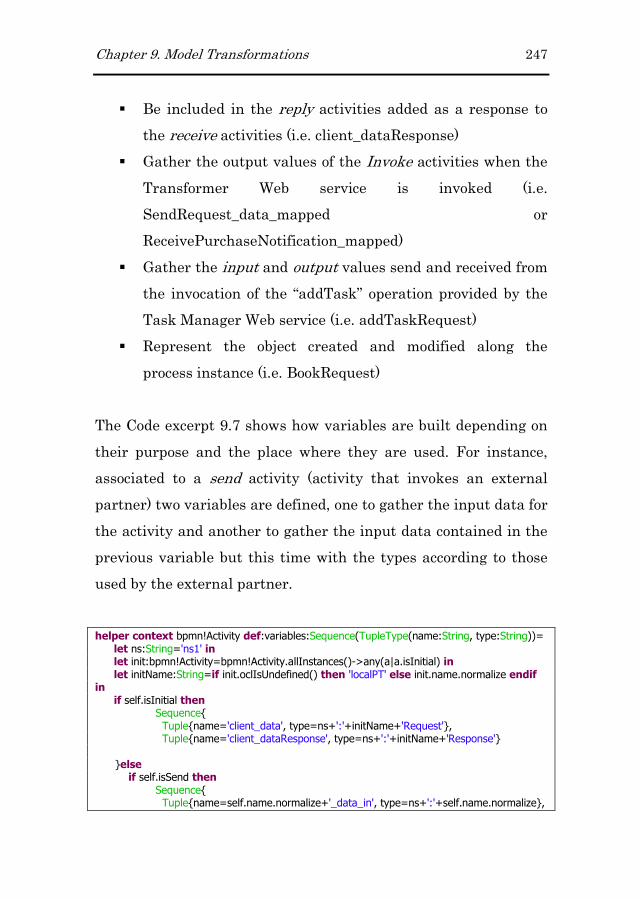
Chapter 9. Model Transformations 247
� Be included in the reply activities added as a response to
the receive activities (i.e. client_dataResponse)
� Gather the output values of the Invoke activities when the
Transformer Web service is invoked (i.e.
SendRequest_data_mapped or
ReceivePurchaseNotification_mapped)
� Gather the input and output values send and received from
the invocation of the “addTask” operation provided by the
Task Manager Web service (i.e. addTaskRequest)
� Represent the object created and modified along the
process instance (i.e. BookRequest)
The Code excerpt 9.7 shows how variables are built depending on
their purpose and the place where they are used. For instance,
associated to a send activity (activity that invokes an external
partner) two variables are defined, one to gather the input data for
the activity and another to gather the input data contained in the
previous variable but this time with the types according to those
used by the external partner.
helper context bpmn!Activity def:variables:Sequence(TupleType(name:String, type:String))= let ns:String='ns1' in let init:bpmn!Activity=bpmn!Activity.allInstances()->any(a|a.isInitial) in let initName:String=if init.oclIsUndefined() then 'localPT' else init.name.normalize endif in if self.isInitial then Sequence{ Tuple{name='client_data', type=ns+':'+initName+'Request'}, Tuple{name='client_dataResponse', type=ns+':'+initName+'Response'} }else if self.isSend then Sequence{ Tuple{name=self.name.normalize+'_data_in', type=ns+':'+self.name.normalize},

248 Chapter 9. Model Transformations
Tuple{name=self.name.normalize+'_data_mapped', type=ns+':'+self.name.normalize+'Request'} }else if self.isReceive then Sequence{ Tuple{name=self.name.normalize+'_mapped', type=ns+':'+self.name.normalize+'Mapped'} , Tuple{name=self.name.normalize+'_data', type=ns+':'+self.name.normalize} }else Sequence{ Tuple{name=self.name.normalize+'_data_in', type=ns+':'+self.name.normalize+'Request'} , Tuple{name=self.name.normalize+'_data_out', type=ns+':'+self.name.normalize+'Response'} }endif endif endif;
Code excerpt 9.7 Helper building the required Variables
Adding the Correlation Set SectionAdding the Correlation Set SectionAdding the Correlation Set SectionAdding the Correlation Set Section
Messages received by BPs require some data in order to identify
the process instance in which they are involved. This ensures that
messages are dispatched to the correct process instance.
Therefore, in order to define a value that is going to identify each
process instance, we create the correlation set section. In
particular we are always going to define a correlation set named
“CS1” whose value is going to be given by the identifier of the
object created and manipulated along the process instance life. For
this purpose, the code shown in the Code excerpt 9.8 creates this
section.
correlationSets: bpel!TCorrelationSets( correlationSet<-correlationSet ), correlationSet: bpel!TCorrelationSet( name<-'CS1', properties<-'ns1'+':'+'identificador' )
Code excerpt 9.8 Code Excerpt creating the Correlation Section

Chapter 9. Model Transformations 249
Moreover, as correlation set names are used in invoke, receive and
reply activities, within the transformations that handle this type
of activities we are going to associate them the generated
correlation set. An example of the code included after these kinds
of activities is shown in Code excerpt 9.9.
<bpel:correlations>
<bpel:correlation initiate="no" set="CS1"/>
</bpel:correlations>
Code excerpt 9.9 Correlation section associated to invoke, receive or reply
activities
The initiate attribute is set to “no” or “yes” depending if the
receive activity corresponds to the first activity of the process
which creates an instance of the process.
Recovering the BusinessRecovering the BusinessRecovering the BusinessRecovering the Business Process Extension Information Process Extension Information Process Extension Information Process Extension Information
We defined an extension to the original BPMN notation to allow
transforming automatically BPMN diagrams into WS-BPEL code
(see chapter 5 for the details). However, since the Babel tool lacks
traceability support for the original elements of the BPMN
notation we have to recover all the information that we loosed
after the execution of this transformation. With this data we can
complete the WS-BPEL code generated by the Babel tool by
specifying Assign activities and Receive and Invoke attributes
such as partner links and port types.
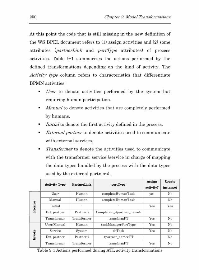
250 Chapter 9. Model Transformations
At this point the code that is still missing in the new definition of
the WS-BPEL document refers to (1) assign activities and (2) some
attributes (partnerLink and portType attributes) of process
activities. Table 9-1 summarizes the actions performed by the
defined transformations depending on the kind of activity. The
Activity type column refers to characteristics that differentiate
BPMN activities:
� User to denote activities performed by the system but
requiring human participation.
� Manual to denote activities that are completely performed
by humans.
� Initial to denote the first activity defined in the process.
� External partner to denote activities used to communicate
with external services.
� Transformer to denote the activities used to communicate
with the transformer service (service in charge of mapping
the data types handled by the process with the data types
used by the external partners).
Activity TypeActivity TypeActivity TypeActivity Type PartnerLinkPartnerLinkPartnerLinkPartnerLink portTportTportTportTypeypeypeype
Assign Assign Assign Assign
activity?activity?activity?activity?
Create Create Create Create
instance?instance?instance?instance?
User Human completeHumanTask yes No
Manual Human completeHumanTask No
Initial - - Yes Yes
Ext. partner Partner-i Completion_<partner_name> Receive
Receive
Receive
Receive
Transformer Transformer transformPT Yes No
User/Manual Human taskManagerPortType Yes No
Service System doTask Yes No
Ext. partner Partner-i <partner_name>PT No
Invoke
Invoke
Invoke
Invoke
Transformer Transformer transformPT Yes No
Table 9-1 Actions performed during ATL activity transformations

Chapter 9. Model Transformations 251
Regarding the values indicated in the remainder columns:
� The Human partner link refers to the service that mediates
between the process and the user.
� The completeHumanTask port type refers to the operation
from the Human service in charge of completing a user task
� Assign activities are required in all cases since it is
necessary to prepare the data to be sent and received to
and from partners.
� The createInstance attribute is only set to “yes” only for
Receive-Initial activities which means that an instance of
the business process is going to be created if it does not
already exists.
� The <partner_name> used in the names of the port types
for Invoke and Receive activities when these are associated
to an external partner refers to the service provided by the
partner.
� For Invoke-User/Manual activities the Assign section has
also to prepare: (1) the group to which the target user
belongs, (2) the name of the task, (3) the user involved in
the task and (4) the current data. All this data is required
since the process is going to invoke an operation of the
Task Manager WS.
Finally, we want to note that after the execution of these
transformations we have a WS-BPEL “model” representing the
WS-BPEL code. However, since we have created the EMF
metamodel of WS-BPEL from the corresponding XML Schema

252 Chapter 9. Model Transformations
document, the serialization of the model to the code is
automatically performed by EMF.
9.2.39.2.39.2.39.2.3 XSD & WSDL GenerationXSD & WSDL GenerationXSD & WSDL GenerationXSD & WSDL Generation
In addition, to complete the WS-BPEL generated code, it is
necessary to make this WS-BPEL code deployable. For this reason
it is necessary to generate also the interface associated to the new
service defined by the WS-BPEL document (expressed in WSDL)
and the data types used by it (expressed in XSD). In this case, also
the Structural and Services model are used to produce these two
files. Specifically, these two models contain a detailed description
of the operations and data types used and produced by the
functionality associated to BP activities. Code excerpt 9.10 shows
how these models are specified at the header of the M2T
transformation which corresponds to:
1. the BPMN metamodel
2. the extension defined to the BPMN notation (defined in the
bpmnx metamodel)
3. the OOWS metamodel, which includes the Structural,
Services, Navigational and Presentation metamodels.
texttransformation ExampleTransformation (in bpmn:"http://stp.eclipse.org/bpmn", in ext:"http://www.example.org/bpmnx", in oows:"http:///oows.ecore") {
Code excerpt 9.10 Header of the MOFScript transformation
In Code excerpt 9.11 the entry point of the transformation is
defined. In it a set of functions are invoked which are in charge of
the generation of each section of the WSDL document (header,
import, types, messages, portTypes, bindings, services,

Chapter 9. Model Transformations 253
partnerLinks and property alias). The complete set of
transformations is included in Appendix E41.
bpmn.BpmnDiagram::main () { //initOperations() file (self.name + ".wsdl"); print(self.xmlHeader()) nl(1) print(self.header()) nl(1) print(self.imports()) nl(1) print(self.types()) nl(1) print(self.messages()) nl(1) print(self.portTypes()) nl(1) print(self.bindings()) nl(1) print(self.services()) nl(1) print(self.partnerLinks()) nl(1) print(self.props()) nl(1)
Code excerpt 9.11 Entry point rule to the transformation to obtain the
WSDL file
The properties and property aliases included in the WSDL file are
used to define the correlation set (set of properties shared by
different messages) defined in the WS-BPEL process. On the one
hand properties define the identifiers used as correlation set in the
WS-BPEL document. On the other hand, since a single property
might exist in several messages, property aliases allow extracting
the value of the property from a message or variable.
bpmn.BpmnDiagram::props():String{ var props:String='' //message ID: props = props + '<vprop:property xmlns:vprop="http://docs.oasis-open.org/wsbpel/2.0/varprop" name="identificador" type="xsd:string"/> ' //Initialize Identifications: oows.objectsOfType(oows.Class)->forEach(c:oows.Class){
41 Available on-line at
http://www.dsic.upv.es/~vtorres/thesis/appendixes/appendixE
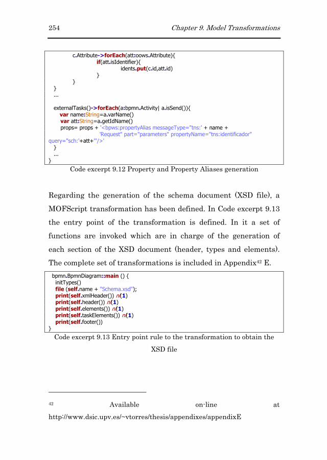
254 Chapter 9. Model Transformations
c.Attribute->forEach(att:oows.Attribute){ if(att.isIdentifier){ idents.put(c.id,att.id) } } } ... externalTasks()->forEach(a:bpmn.Activity| a.isSend()){ var name:String=a.varName() var att:String=a.getIdName() props= props + '<bpws:propertyAlias messageType="tns:' + name + 'Request" part="parameters" propertyName="tns:identificador" query="sch:'+att+'"/>' } ... }
Code excerpt 9.12 Property and Property Aliases generation
Regarding the generation of the schema document (XSD file), a
MOFScript transformation has been defined. In Code excerpt 9.13
the entry point of the transformation is defined. In it a set of
functions are invoked which are in charge of the generation of
each section of the XSD document (header, types and elements).
The complete set of transformations is included in Appendix42 E.
bpmn.BpmnDiagram::main () { initTypes() file (self.name + "Schema.xsd"); print(self.xmlHeader()) nl(1) print(self.header()) nl(1) print(self.elements()) nl(1) print(self.taskElements()) nl(1) print(self.footer()) }
Code excerpt 9.13 Entry point rule to the transformation to obtain the
XSD file
42 Available on-line at
http://www.dsic.upv.es/~vtorres/thesis/appendixes/appendixE

Chapter 9. Model Transformations 255
In this case we generate separately data types and elements. The
operations in charge of this generation are elements() and
taskElements() respectively.
9.3 Model Transformations to Generate the User
Interface
The second type of artefact obtained from the models built at the
modelling level corresponds to the different code files that
constitute the Web application. The different transformations
(M2M and M2T) that have been defined in this case were briefly
presented Figure 9.2 and produce the following assets:
� The Navigational Model that supports the execution of the
original BP definitions.
� The set of files corresponding to the Navigational Model in
terms of the Tapestry Web Framework.
The following subsections detail the process followed in each case.
9.3.19.3.19.3.19.3.1 BPMN to OOWS Navigational ModelBPMN to OOWS Navigational ModelBPMN to OOWS Navigational ModelBPMN to OOWS Navigational Model
The set of M2M transformations defined to obtain a first version of
the OOWS Navigational model uses as input the BPM model as
well as the Structural and Services models. The particularity of
these transformations is that only apply to tasks that are included
in lanes defined in the BPM as «role-one» and «role-any» which
correspond to tasks performed by human beings. In the following
paragraphs we present textually the set of rule transformations
defined to obtain the OOWS Navigational model. The
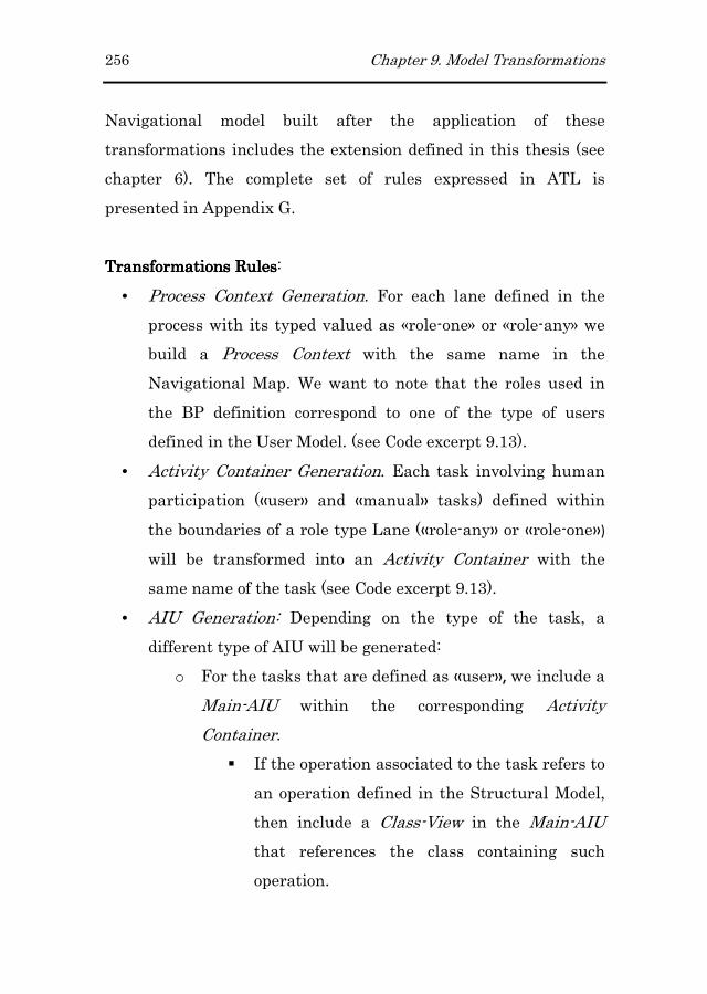
256 Chapter 9. Model Transformations
Navigational model built after the application of these
transformations includes the extension defined in this thesis (see
chapter 6). The complete set of rules expressed in ATL is
presented in Appendix G.
TransformationsTransformationsTransformationsTransformations RulesRulesRulesRules:
• Process Context Generation. For each lane defined in the
process with its typed valued as «role-one» or «role-any» we
build a Process Context with the same name in the
Navigational Map. We want to note that the roles used in
the BP definition correspond to one of the type of users
defined in the User Model. (see Code excerpt 9.13).
• Activity Container Generation. Each task involving human
participation («user» and «manual» tasks) defined within
the boundaries of a role type Lane («role-any» or «role-one»)
will be transformed into an Activity Container with the
same name of the task (see Code excerpt 9.13).
• AIU Generation: Depending on the type of the task, a
different type of AIU will be generated:
o For the tasks that are defined as «user», we include a
Main-AIU within the corresponding Activity
Container.
� If the operation associated to the task refers to
an operation defined in the Structural Model,
then include a Class-View in the Main-AIU
that references the class containing such
operation.
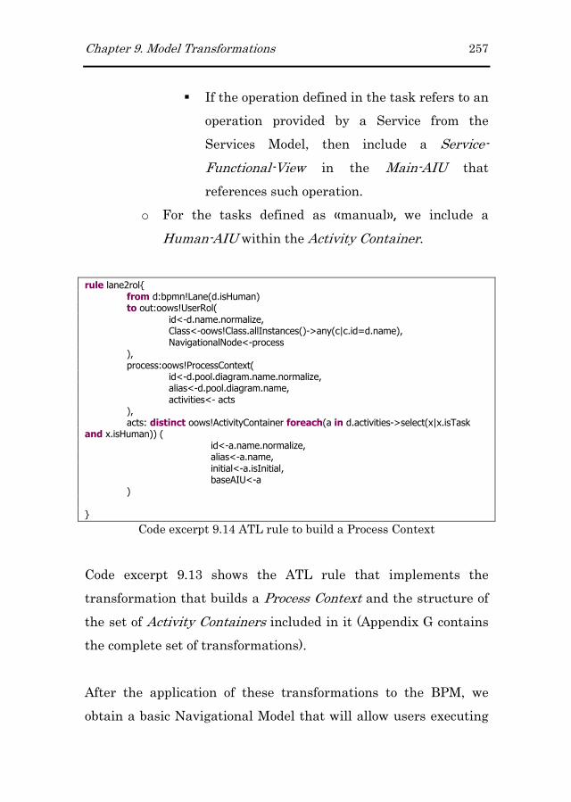
Chapter 9. Model Transformations 257
� If the operation defined in the task refers to an
operation provided by a Service from the
Services Model, then include a Service-
Functional-View in the Main-AIU that
references such operation.
o For the tasks defined as «manual», we include a
Human-AIU within the Activity Container.
rule lane2rol{ from d:bpmn!Lane(d.isHuman) to out:oows!UserRol( id<-d.name.normalize, Class<-oows!Class.allInstances()->any(c|c.id=d.name), NavigationalNode<-process ), process:oows!ProcessContext( id<-d.pool.diagram.name.normalize, alias<-d.pool.diagram.name, activities<- acts ), acts: distinct oows!ActivityContainer foreach(a in d.activities->select(x|x.isTask and x.isHuman)) ( id<-a.name.normalize, alias<-a.name, initial<-a.isInitial, baseAIU<-a ) }
Code excerpt 9.14 ATL rule to build a Process Context
Code excerpt 9.13 shows the ATL rule that implements the
transformation that builds a Process Context and the structure of
the set of Activity Containers included in it (Appendix G contains
the complete set of transformations).
After the application of these transformations to the BPM, we
obtain a basic Navigational Model that will allow users executing

258 Chapter 9. Model Transformations
the corresponding BPs. Based on the case study developed in
Appendix C, Figure 9.4 depicts the Process Context generated for
the secretary role.
«process context»
BookPurchaseRequest
«activity container» ValidateRequest
«Main-AIU»
ValidateRequest
«class-view»
Member
-name
-surname
-login
+validateRequest()
«class-view»
RequestBook
-title
-authors
-editorial
-numEdition
-publishDate
-units
E
state == pending or denied
«activity container» PickUpBooks
«Human-AIU»
PickUpBooks
«class-view»
RequestBook
-title
-isbn
-units
state == approved
Figure 9.4 Basic Process Context Generated for the Secretary role
This Process Context includes two activity containers (one for each
user task assigned to the secretary role), among which are a Main-
AIU and a Human-AIU.

Chapter 9. Model Transformations 259
9.3.29.3.29.3.29.3.2 Code Generation for a Web FrameworkCode Generation for a Web FrameworkCode Generation for a Web FrameworkCode Generation for a Web Framework
Navigational and Presentation models defined by OOWS include
web page abstractions that can be mapped onto any language or
framework capable of implementing web applications. In
particular, in this work we decided to make use of a web
framework that facilitates the construction of the final application.
From the wide range of available web frameworks we finally chose
the open-source framework Tapestry43. Briefly, the main reasons
for this decision were the use made by Tapestry of (1) a
component-based model, (2) the Inversion of Control (IoC) pattern
and (3) the Model-View-Controler (MVC) pattern.
A Tapestry component, technically know as JWC (Java Web
Component) is a web component that can be configured,
instantiated and aggregated to take part in other components.
These components can be from an input text to a flow control
component such as an “if” clause. In addition, the set of
components is extensible allowing the developer defining her own
components.
The IoC pattern avoids the software developer dealing with low
level tasks such as controlling references between objects. This
task is relegated to a container (which is called HiveMind44 in the
43 http://tapestry.apache.org/
44 http://hivemind.apache.org/

260 Chapter 9. Model Transformations
Tapestry framework) which injects all dependencies, references
and objects related to a given object.
The MVC pattern is a software architecture pattern that
separates in three different components the data, the presentation
and the logic of the application. This pattern is widely used in the
development of web applications, where the View is constituted by
HTML templates and the code providing dynamic data for the
page, the Model is constituted by the data model (which is usually
represented by a class diagram) and the Controller is constituted
by the logic of the application.
As a result of this decision, the obtained benefits are the following:
� Simplicity, consistency and efficiency of the built code.
� Tapestry uses standard HTML code for their templates.
Moreover, following the IoC pattern, the semantics of the
components is included in separate configuration files, fact
that allows keeping templates just with HTML code.
Moreover, we can reuse HTML code by converting it into a
Tapestry component, which can then be used by means of
the proper identification.
� Tapestry components are easy to use but also to create.
� The use of the IoC pattern avoids the developer dealing
with low level aspects.
� It includes useful predefined components such as an input
validation system, an error report, own AJAX components,
etc.
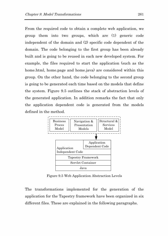
Chapter 9. Model Transformations 261
From the required code to obtain a complete web application, we
group them into two groups, which are (1) generic code
independent of the domain and (2) specific code dependent of the
domain. The code belonging to the first group has been already
built and is going to be reused in each new developed system. For
example, the files required to start the application (such as the
home.html, home.page and home.java) are considered within this
group. On the other hand, the code belonging to the second group
is going to be generated each time based on the models that define
the system. Figure 9.5 outlines the stack of abstraction levels of
the generated application. In addition remarks the fact that only
the application dependent code is generated from the models
defined in the method.
BusinessProces Model
Application Independent Code
Tapestry Framework
Servlet Container
Java
Application Dependent Code
Navigation & Presentation
Models
Structural & Services Model
Figure 9.5 Web Application Abstraction Levels
The transformations implemented for the generation of the
application for the Tapestry framework have been organized in six
different files. These are explained in the following paragraphs.
262 Chapter 9. Model Transformations
Transformations associated to the process itself:
� Model.m2tModel.m2tModel.m2tModel.m2t: This transformation generates the java class
(Model.java) in charge of keeping the information about the
existing processes, activities and roles. Moreover, it also
keeps its data and the way in which processes, activities
and roles are related.
� ProcessJava.m2tProcessJava.m2tProcessJava.m2tProcessJava.m2t: This transformation generates the java
class (Processes.java) in charge of redirecting the user to
the appropriate web page depending on the state of the
process.
Transformations associated to process Activities:
� ActivitiesHTML.m2tActivitiesHTML.m2tActivitiesHTML.m2tActivitiesHTML.m2t: It generates the HTML code of the
application (the view from the MVC pattern).
� ActivitiesPage.m2tActivitiesPage.m2tActivitiesPage.m2tActivitiesPage.m2t: This transformation generates the
.page files gathering the XML code corresponding to the
declarations of the Tapestry components.
� ActivititesJava.m2tActivititesJava.m2tActivititesJava.m2tActivititesJava.m2t: It generates the java code associated
to the HTML generated by the ActivitiesHTML
transformation (the controller from the MVC pattern).
Transformations associated to the Structure of the Domain
� ClassDiagram.m2tClassDiagram.m2tClassDiagram.m2tClassDiagram.m2t: : : : It generates the classes defining the
domain of the application (the Model from the MVC
pattern). Since the logic of the local system is going to be
provided by the OlivaNova tool, the generated classes in
this case represent locally the objects provided by the tool.
This integration is possible since applications generated
Chapter 9. Model Transformations 263
with the OlivaNova Transformation Engines provide
Components and Web Services to make use of the
application logic. In both cases, domain classes are
available to be queried and to access their business logic
functionality.
For a whole description of these transformation see Appendix H45,
where all the MOFScript code to implement these transformations
is included.
After the application of these transformations, a ready to run Web
application is built. The different generated files are distributed
among different folders according to the Tapestry requirements. A
complete description of this structure is presented in chapter 10.
9.4 Conclusions
This chapter has presented in detail the set of transformations
that have been defined to move the system specification performed
following the OOWS approach to a particular implementation. As
transformation languages we have used ATL and MOFScript to
implement M2M and M2T transformations respectively. On the
one hand we have detailed the process performed to obtain from a
business process specification depicted in the BPMN “extended”
notation to an equivalent definition of the process in the
executable WS-BPEL language. For this purpose, in addition to
45 Available on-line at
http://www.dsic.upv.es/~vtorres/thesis/appendixes/appendixH
264 Chapter 9. Model Transformations
the already mentioned transformation languages we have made
use of the BPMN2BPEL java tool. This tool allows us generating a
preliminary version of the executable process in the WS-BPEL
language. Then making use of the BPM, Structural and Services
models we have completed the WS-BPEL document and also
generated the file defining the interface of the process (in a WSDL
file) as well as the data types used by it.
On the other hand we have detailed the process of deriving the
Web application supporting the business processes defined in the
BPM. This process is performed in two steps. First of all, we derive
from the BPM the Navigational and Presentation model which
represent in an abstract way the elements that make up the web
pages of the web application. Then, in a second stage we
instantiate these models into a particular Web framework,
Tapestry in this case. As a result, a ready to run Web application
supporting the execution of the originally specified business
processes is built.

Chapter 10
10 Tool Support
Models in software engineering were initially used for
documentation purposes. These were relegated to play a secondary
role within the software development process. However,
approaches such as the Model Driven Development (MDD)
changed that reality. This approach brought models as first class
citizens during the software development process. The main
advantage of this approach was that software applications could
be automatically generated from models. In addition, nowadays,
the maturity reached by technologies and standards allow turning
the MDD approach into reality. Examples of these mature tools
are the Eclipse Modelling Project (EMP) or the Domain-Specific
Language tools from Microsoft.
This chapter presents the BIZZY tool which has been developed in
the context of the EMP where a set of Eclipse plugin (model
editors and model transformation languages) have been combined
to completely support the development process proposed in this
thesis. On the one hand, the included model editors allow
developers creating and manipulating the set of models defined in
this work (Structural, Services, Business Process Navigation and

266 Chapter 10. Tool Support
Presentation Models). On the other hand, model transformation
languages have been used to implement model-to-model (M2M)
and model-to-text (M2T) transformations that allow obtaining
respectively other models (specifically the Navigational model)
and their equivalent representation but this time in terms of a
technological representation.
The chapter has been organized as follows. First, section 10.1
takes up again the development process presented in chapter 4 to
detail the tools used in each step of the process. Then, in section
10.2, the development process is presented step by step by
detailing the tools used and the artefacts consumed and generated
in each step. Section 10.3 presents how the artefacts obtained
after the execution of the implemented model transformations are
deployed to a Web server. Finally, this chapter is concluded in
section 10.4.
10.1 Tool Overview
The generation of BP-driven Web applications is performed by
using different model editors and model transformations along the
different steps defined in the development process. According with
the development process presented in chapter 4, this process is
divided into two main steps which relate to system specification
(problem space) and system generation (solution space). The
coordinated use of these model editors and model transformations
allows generating the Web application according to the models
specified at the problem space. Figure 10.1 shows the tool support

Chapter 10. Tool Support 267
provided for each of the steps defined in the process. In this figure,
when a model transformation is performed, this has been
indicated by means of a gear image, which includes in the type of
transformation performed (M2M, M2T or both).
1st Stage – Problem Space
2nd Stage – Solution Space
OOWS-BP
Analyst
«human-being»
Developer
«human-being»
Business Process
Analysis
+
System
Specification
+
Web
Specification
Business Process
Design
Bizzy Tool
«system»
«model»
Business Processes
[incomplete]
«model»
OO-Method Model
«model»
Business Processes
[complete]
«model»
OOWS
Models
[basic]
«code»
WS-BPEL
document
Web Application
Generation
Enrich?
+
Enrich Web
Specification
YesNo
+
+
Executable
Business Process
«code»
Tapestry
files
«model»
OOWS
Models
[enriched]
This sub-process
involves
model2text
transformations
«model»
Services Model
This task
includes
model2text
transformations
Structural Model
Functional Model
Dynamic Model
Services Model
BPMN Extension Navigational &
Presentation Models
BP Model
M2M
Transf.
BPMN2BPEL Babel Tool
M2M and M2T Transf.
M2T Transf.
Navigational &
Presentation Models
1.1
1.2
1.3
1.4 2
3
4
Figure 10.1 Tool Support for the OOWS-BP Development Process

268 Chapter 10. Tool Support
Model editors and transformations used along the development
process have been built from a set of tools included in the Eclipse
project, specifically from the Eclipse Modeling Framework46
(EMF). EMF includes tools for the generation, edition and
serialization of models conforming to Ecore metamodels (an
implementation of the OMG’s Essential MOF to represent
metamodels). In the BIZZY tool, all the used metamodels (BPMN,
WS-BPEL and OOWS) are represented as Ecore metamodels. In
some cases, the Ecore metamodels were built from the
corresponding XML Schemas (EMF permits the generation of
Ecore metamodels from XML Schemas). In other cases, a new
Ecore metamodel had to be built.
With regard to model editors, most of the model editors included
in the BIZZY tool are provided as a tree-based EMF editor. The
only graphical editor included in the tool is the BPMN Modeller47
that has been developed in the SOA Tools Platform (STP).
With regard to model transformations, two different languages
have been used. On the one hand, the Atlas Transformation
Language48 (ATL) was used to deal with M2M transformations.
Specifically, we have implemented in this language the
transformations that allow transforming (1) the Business Process
Model (BPM) into the corresponding OOWS Navigational Model
46 http://www.eclipse.org/modeling/emf/
47 http://www.eclipse.org/stp/bpmn/
48 http://www.eclipse.org/m2m/atl/
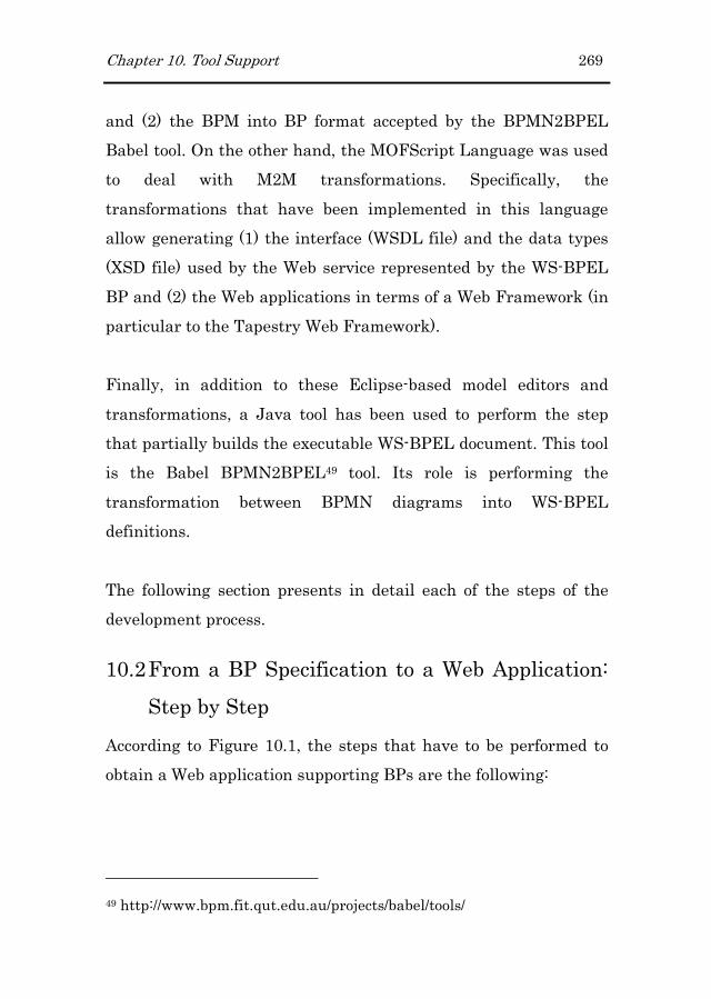
Chapter 10. Tool Support 269
and (2) the BPM into BP format accepted by the BPMN2BPEL
Babel tool. On the other hand, the MOFScript Language was used
to deal with M2M transformations. Specifically, the
transformations that have been implemented in this language
allow generating (1) the interface (WSDL file) and the data types
(XSD file) used by the Web service represented by the WS-BPEL
BP and (2) the Web applications in terms of a Web Framework (in
particular to the Tapestry Web Framework).
Finally, in addition to these Eclipse-based model editors and
transformations, a Java tool has been used to perform the step
that partially builds the executable WS-BPEL document. This tool
is the Babel BPMN2BPEL49 tool. Its role is performing the
transformation between BPMN diagrams into WS-BPEL
definitions.
The following section presents in detail each of the steps of the
development process.
10.2 From a BP Specification to a Web Application:
Step by Step
According to Figure 10.1, the steps that have to be performed to
obtain a Web application supporting BPs are the following:
49 http://www.bpm.fit.qut.edu.au/projects/babel/tools/

270 Chapter 10. Tool Support
1. System System System System SSSSpecification:pecification:pecification:pecification: Specify the different aspects of the
system (Structure, behaviour) by means of the
corresponding editors.
2. Generation of the Web Generation of the Web Generation of the Web Generation of the Web System Navigation:System Navigation:System Navigation:System Navigation: Execute a M2M
transformation that generates the Navigational model
required to support the execution of the BPs defined in step
1. This is an ATL transformation that is executed from the
ATL plug-in for Eclipse.
3. Generation of the Web System GUI:Generation of the Web System GUI:Generation of the Web System GUI:Generation of the Web System GUI: Execute a set of M2T
transformations that generate the Web application in
terms of the Tapestry Web framework. These
transformations are implemented in MOFScript and are
executed from the MOFScript tool developed as an Eclipse
plug-in.
4. Generation of WSGeneration of WSGeneration of WSGeneration of WS----BPEL executable BPsBPEL executable BPsBPEL executable BPsBPEL executable BPs: Execute a set of
M2M, M2T and the BPMN2BPEL Babel tool to obtain an
executable definition of the BPs defined in step 1.
Depending on the case, these transformations have been
implemented in ATL and MOFScript.
The following subsections present each of these steps by means of
the “Book Request Purchase” long-running BP case study (a
complete description is provided in Appendix C). For each step we
detail its sub steps (if any), the required models, the tool used and
the produced artefacts.

Chapter 10. Tool Support 271
10.2.110.2.110.2.110.2.1 Step 1: System SpecificationStep 1: System SpecificationStep 1: System SpecificationStep 1: System Specification
Along this step the system is modelled by the developer in terms of
the models proposed by the method. These models represent the
system in an independent technology manner. This step is made
up in turn of four steps and the order in which these are built can
vary from case to case. However, since we start from a BP
specification, we propose the following order:
1.1 Build an initial BP definition. This step is performed by
means of the BPMN Modeller included in the STP (see
Figure 10.2). This step constitutes the first attempt to build
the Business Process Model (BPM) defined in the proposal.
Figure 10.2 STP BPMN Modeller
1.2 Build the Structural, Dynamic and Functional models
defined by the OO-Method approach. This step is
performed by means of the OLIVANOVA Modeller.

272 Chapter 10. Tool Support
Figure 10.3 Different Editors provided by the OLIVANOVA Modeller
These models are translated into code by means of the
OLIVANOVA Transformation Engines. The integration of the code
generated by these engines was solved in (Valverde et al., 2007).
In this work, authors developed a Business Façade interface which
exposes a set of methods that are redefined according to the
underlying business logic. This façade is used to build and send
XML messages to the components that encapsulate the business
logic specified in the OLIVANOVA Modeller.
1.3 Build the Services Model included in the OO-Method
approach. This model allows specifying the functionality
that is provided by external partners at the modelling level.
Nowadays, this model is built manually from the WSDL
interface provided by external partners. This is performed
by means of the tree-based EMF editor generated for the
Services Model.

Chapter 10. Tool Support 273
Figure 10.4 Tree-based EMF editor for the Services Model
1.4 Complete the BP definition that has been built in step 1.1
according the BPMN extension presented in chapter 5. This
extension allows specifying the functionality that supports
each of the BP activities and the behaviour of the human
roles involved in the BP. This completion is performed by
means of a three-based EMF editor which extends some of
the elements defined in the original BPMN notation (see
Figure 10.5). After this step, the BPM is completed and can
be used to produce different artefacts.
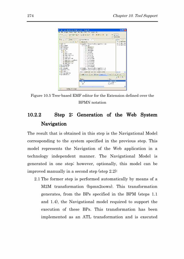
274 Chapter 10. Tool Support
Figure 10.5 Tree-based EMF editor for the Extension defined over the
BPMN notation
10.2.210.2.210.2.210.2.2 Step 2: Step 2: Step 2: Step 2: Generation of the Web System Generation of the Web System Generation of the Web System Generation of the Web System
NavigationNavigationNavigationNavigation
The result that is obtained in this step is the Navigational Model
corresponding to the system specified in the previous step. This
model represents the Navigation of the Web application in a
technology independent manner. The Navigational Model is
generated in one step; however, optionally, this model can be
improved manually in a second step (step 2.2):
2.1 The former step is performed automatically by means of a
M2M transformation (bpmn2oows). This transformation
generates, from the BPs specified in the BPM (steps 1.1
and 1.4), the Navigational model required to support the
execution of these BPs. This transformation has been
implemented as an ATL transformation and is executed

Chapter 10. Tool Support 275
from the ATL plug-in for Eclipse. This transformation50 has
been previously presented in chapter 9. Figure 10.6 shows
the input and output artefacts of the “bpmn2oows”
transformation.
Figure 10.6 From BPM to OOWS Navigational Model
2.2 Although the Navigational model obtained previously in
step 2.1 it already supports the execution of the defined
BPs, this model can be manually enriched to include
information to improve the final generated Web
application. Specifically, in this step we can include
complementary information that is kept in the system to
help users in completing their tasks. This step is performed
manually by the developer and it is done by means of the
tree-based EMF editor built for the Navigational model.
10.2.310.2.310.2.310.2.3 Step 3: Step 3: Step 3: Step 3: Generation of the Web System GUIGeneration of the Web System GUIGeneration of the Web System GUIGeneration of the Web System GUI
Once the whole system is specified at the problem space, we can
proceed with the execution of M2T transformations that generate
the Web application in terms of the Tapestry Web framework.
50 Available on-line at
http://www.dsic.upv.es/~vtorres/thesis/appendixes/appendixG
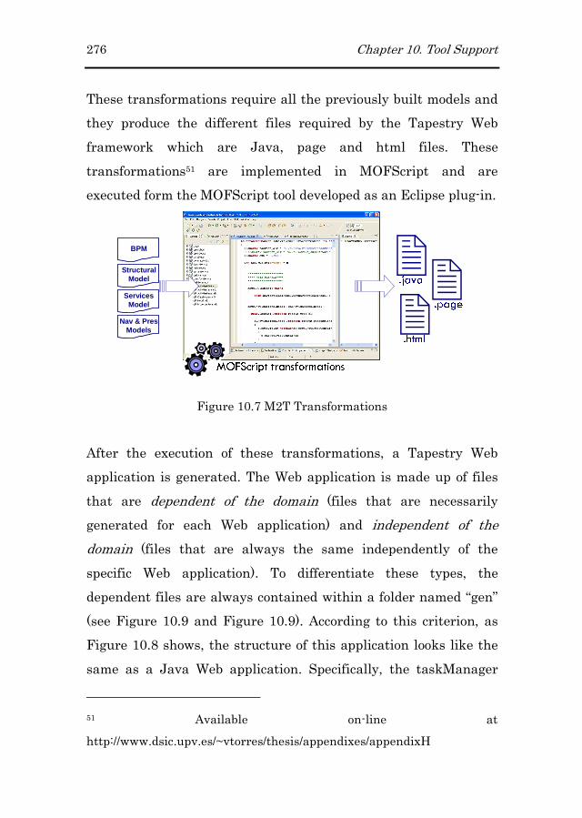
276 Chapter 10. Tool Support
These transformations require all the previously built models and
they produce the different files required by the Tapestry Web
framework which are Java, page and html files. These
transformations51 are implemented in MOFScript and are
executed form the MOFScript tool developed as an Eclipse plug-in.
��
�
BPM
StructuralModel
ServicesModel
Nav & PresModels
Figure 10.7 M2T Transformations
After the execution of these transformations, a Tapestry Web
application is generated. The Web application is made up of files
that are dependent of the domain (files that are necessarily
generated for each Web application) and independent of the
domain (files that are always the same independently of the
specific Web application). To differentiate these types, the
dependent files are always contained within a folder named “gen”
(see Figure 10.9 and Figure 10.9). According to this criterion, as
Figure 10.8 shows, the structure of this application looks like the
same as a Java Web application. Specifically, the taskManager
51 Available on-line at
http://www.dsic.upv.es/~vtorres/thesis/appendixes/appendixH

Chapter 10. Tool Support 277
folder (which corresponds to the “Book Request Purchase” case
study) is made up of three folders (the “gen”, “images” and “WEB-
INF”) and a set of html, page and css files.
Figure 10.8 Web application folder within the TOMCAT Web server
The “gen” folder contains the html templates of the different Web
pages of the application and, when applies, the associated page
files (remember that these files specify the Tapestry components
used in the templates).
The html and page files contained in this folder are files
independent of the domain and correspond to the initial web page
when the Web application is started (Home.html) and the
navigation provided to a specific user regarding to BPs
(Processes.html).
The default.css file is the Cascading Style Sheet used in the Web
application which defines colours, fonts, layout and other aspects
of the presentation of the web pages. The images folder contains
the application’s images used by the Web pages.

278 Chapter 10. Tool Support
Figure 10.9 WEB-INF Folder Structure
Finally, the WEB-INF directory contains all the inner workings of
a Java Web application. This directory contains three subfolders
which are:
� classesclassesclassesclasses folder: This folder contains the Java classes that
implement the functionality of the Web application.
� liblibliblib folder: This folder contains all the libraries required by
the Web application. Specifically, the Tapestry libraries are
placed in this folder.
� METAMETAMETAMETA----INFINFINFINF folder: This directory contains the manifest file
which describes the package that is created from the Web
application.
� web.xmlweb.xmlweb.xmlweb.xml file: This file is the deployment descriptor which
serves to tell the Web server all of the most important
details about the Web application and its configuration.

Chapter 10. Tool Support 279
10.2.410.2.410.2.410.2.4 Step 4: Step 4: Step 4: Step 4: Generation of WSGeneration of WSGeneration of WSGeneration of WS----BPEL executable BPEL executable BPEL executable BPEL executable
BPsBPsBPsBPs
The generation of the WS-BPEL BP is performed in four steps.
The use of the BPMN2BPEL Babel tool to generate a partial
definition of the WS-BPEL document forces us to prepare BP
definitions (those modelled in the BPM) according to the format
required by this tool. Therefore, the steps required to obtain a
complete WS-BPEL document are the following:
4.1 Execute the bpmn2babel M2M transformation to prepare
the BPs defined in step 1.1 into the format accepted by the
BPMN2BPEL Babel tool. This transformation52 has been
implemented in ATL and it is executed from the ATL plug-
in for Eclipse. Figure 10.10 shows the models consumed
and generated by the bpmn2babel transformation.
Figure 10.10 M2M transformation to prepare BP definitions according to
the Babel tool
4.2 Execute the BPMN2BPEL Babel tool to obtain a partial
definition of the executable BP defined in step 1.1. This
52 Available on-line at
http://www.dsic.upv.es/~vtorres/thesis/appendixes/appendixD

280 Chapter 10. Tool Support
step is automated by means of an Ant script which defines
targets to invoke the Babel Java tool. Figure 10.11 shows
the consumed and generated models after the execution of
the BPMN2BPEL Babel tool.
Figure 10.11 Generation of a partial WS-BPEL BP
4.3 Execute the bpelRefinement M2M transformation which
completes the WS-BPEL document obtained in step 4.2. As
Figure 10.12 shows, this transformation uses the
Structural, Services and Business Process Model to
complete the WS-BPEL document generated previously in
step 4.2. This transformation53 has been implemented in
ATL and it is executed from the ATL plug-in for Eclipse.
BPM
StructuralModel
ServicesModel
Figure 10.12 Generation of a complete WS-BPEL BP
53 Available on-line at
http://www.dsic.upv.es/~vtorres/thesis/appendixes/appendixF
Chapter 10. Tool Support 281
4.4 Execute the M2T transformations that generate the
interface and the data type files corresponding to the WS-
BPEL obtained previously. These files are necessary since
the WS-BPEL BP is in turn a Web service. These files are
generated from the Structural, Services and Business
Process Models. These transformations54 have been
implemented in MOFScript and it is executed from the
MOFScript plug-in for Eclipse.
BPM
StructuralModel
ServicesModel
Figure 10.13 Generation of the Interface and Data types used by the WS-
BPEL BP
When the WS-BPEL document and the WSDL and XSD files have
been generated we can bring them into the ActiveBPEL Eclipse
environment to proceed with the deployment of the WS-BPEL BP
(see section 10.3.2).
10.3 Deployment
Once the system has been obtained in terms of an implementation
technology, this has to be deployed in a Web server. Both the Web
applications and the WS-BPEL are deployed in a Web server.
Then, when the server is started both applications will be served
54 Available on-line at
http://www.dsic.upv.es/~vtorres/thesis/appendixes/appendixE

282 Chapter 10. Tool Support
by the server. The following subsections explain how the interface
of the Web application and the WS-BPEL BP are deployed in the
Web server.
10.3.110.3.110.3.110.3.1 Web Application DeploymentWeb Application DeploymentWeb Application DeploymentWeb Application Deployment
Before deploying the Web application in a Web server it is
necessary to compile all the Java files generated in step 3. These
tasks (compilation and deployment) have been automated in an
Ant script (Code excerpt 10.1). After the execution of these tasks, a
Web application with the structure shown in section 10.2.3 is
created.
<target name="build"
description="Compile main source tree java files">
<mkdir dir="${build.dir}"/>
<javac destdir="${build.dir}" target="1.5" debug="true"
deprecation="false" optimize="false"
failonerror="true">
<src path="${src.dir}"/>
<classpath refid="master-classpath"/>
</javac>
</target>
<target name="deploy" depends="build"
description="Deploy application">
<copy todir="${deploy.path}/${name}"
preservelastmodified="true">
<fileset dir="${web.dir}">
<include name="**/*.*"/>
</fileset>
</copy>
</target>
Code excerpt 10.1 Build.xml excerpt

Chapter 10. Tool Support 283
10.3.210.3.210.3.210.3.2 WSWSWSWS----BPEL DeploymentBPEL DeploymentBPEL DeploymentBPEL Deployment
The deployment of a WS-BPEL BP to a Web server is performed
from the ActiveBPEL Eclipse tool (see Figure 10.14). The steps
that have to be done to proceed with the deployment are the
following:
� Import a skeleton project for ActiveBPEL. This skeleton
includes:
o A WSDL folder which contains the wsdl files of the
external partners (in this case this corresponds to
the Central Library partner) and the task manager
(this service is always used by the generated WS-
BPEL process to deal with the human limitation
found in the WS-BPEL version used in this work
(version 1.1)).
o PDD (Process Deployment Description file): This file
indicates the urls where the different services
involved in the WS-BPEL are located.
� Copy the automatically generated .bpel file (see section
10.2.4) into the imported project (bookRequest.bpel in
Figure 10.14).
� Copy the generated wsdl and xsd files (10.2.4) into the
imported project (bookRequest.wsdl and
bookRequestSchema.xsd in Figure 10.14).
� Export the PDD file as a Business Process Archive (.bpr)
file. As a result, an archive deployment file is created
(bookRequest.bprd file in Figure 10.14).

284 Chapter 10. Tool Support
Figure 10.14 ActiveBPEL prepared environment
The WS-BPEL deployed process can be tested from the “BPEL
Administrative Console” which can be reached from the
“Administrative Servlets” provided with the activeBPEL engine.
This console allows checking that the deployment was successful.
After the deployment of the WS-BPEL processes, the active-bpel
folder shown in Figure 10.15 is created.
Figure 10.15 Active-bpel folder within the TOMCAT Web server

Chapter 10. Tool Support 285
10.4 Conclusions
In this chapter we have presented the set of model editors and
transformations used along the development process to generate a
BP-driven Web application. We have detailed for each step of the
process the artefacts consumed and generated and the tool used to
complete each step.
Model editors have been used to specify the different aspects that
characterize BP-driven Web applications. Most of them have been
provided as a tree-based EMF editor. On the other hand, model
transformations have been implemented to obtain (1) a Java Web
application and (2) the set of WS-BPEL BP according to the
system specified at the modelling level. To implement model
transformations we have used two different languages which are
ATL and MOFScript. These languages have been used to
implement model-to-model and model-to-text transformations
respectively.
Additionally, we have explained how the generated artefacts (Web
application in terms of the Tapestry Web Framework and WS-
BPEL processes) are deployed in a Web server. On the one hand,
the Web application has been generated according to the folder
structure required for a Java Web application. On the other hand,
the WS-BPEL process is automatically deployed to the Web server
through the ActiveBPEL Eclipse environment.

Chapter 11
11 Conclusions & Further Work
In this thesis, we have presented a methodological solution to cope
with the automatic generation of BP-driven Web applications. To
achieve this goal, we have developed a solution within the Web
engineering field that is inspired on the architecture of the
Business Process Management Solutions (BPMS). Furthermore,
the proposed solution is also based on the Model Driven
Engineering field, where the definition of model transformations
allows us to move the system that is specified at the modelling
level into a specific implementation technology.
This last chapter introduces the conclusions of the work developed
in this thesis. First, we present the main contributions to the Web
engineering community. Then, we outline the ongoing and future
work that has emerged from this thesis. Finally, we present the
publications that have been produced throughout the development
of this work.
11.1 Main Contributions
The main contributions of this work are:

288 Chapter 11. Conclusions & Further Work
� We have defined a complete process to carry out the
development of BP-driven Web applications. This process
extends from the modelling phase (the phase where the
system is represented in terms of a set of models) through
the generation phase (the phase that applies a set of
transformation rules to obtain the executable artefacts).
� At the modelling level, we have defined a set of
abstractions that represent navigational and presentation
properties found during the business process (BP)
execution. These abstractions have been introduced into
the OOWS Web Engineering method.
� We have modified the architecture of the generated Web
applications to properly handle BPs. As a result, we have
introduced a process engine into the architecture of these
systems. This process engine allows the construction of
more lightweight navigational models, where the process
flow is maintained inside the process definition.
� Based on the MDE, we have defined a set of model
transformations to obtain (1) executable process definitions
expressed in the WS-BPEL language and (2) the set of files
(.java, .html and .page) necessary to deploy an application
in terms of a Web framework, specifically the Tapestry Web
framework55.
� We have developed a tool (the BIZZY tool) that implements
the ideas presented in this work. The tool has been
developed applying the latest trends in the MDE field. It
55 http://tapestry.apache.org/

Chapter 11. Conclusions & Further Work 289
has been built using tools that are included in the Eclipse
development environment (the Eclipse Modeling project
and the SOA Tool Platform project) and the BPMN2BPEL
Java tool56. Tools such as ATL and MOFScript have been
used to implement the transformations defined in the
proposal and EMF has been used to manipulate the models
defined in the method. Finally, the BPMN editor from the
STP Project has been used to model BPs defined in the
Business Process Model included in the proposal.
11.2 Further Work
The research presented here is not a closed work and there are
several interesting directions that can be taken to provide the
proposal with a wider spectrum of application. The following list
summarizes the research activities that are planned to continue
this work.
� Business Business Business Business PPPProcess rocess rocess rocess SSSSemanticsemanticsemanticsemantics. We propose to present
semantic information related to the BPs supported by our
generated Web applications. This extra information will
provide potential consumers with a more complete
description of the offered functionality. To achieve this
goal, these services must be described in semantic
languages such as OWL-S (Burstein et al., 2004) or WSMO
(Roman et al., 2005). In keeping with the MDE trends
applied in this work, we should define mappings that allow
56 http://www.bpm.fit.qut.edu.au/projects/babel/tools/

290 Chapter 11. Conclusions & Further Work
us to translate the BPs represented in our systems into any
semantic language.
� Business Business Business Business RRRRulesulesulesules. Web service technology has propitiated the
existence of multiple service providers offering similar
services. Since performing an automatic selection based on
a set of variables is very important, we plan to study how
these business rules can be defined within the method
following the MDE trends on which this work is based.
� Assisting the User during Business PrAssisting the User during Business PrAssisting the User during Business PrAssisting the User during Business Process Definitionocess Definitionocess Definitionocess Definition. It is
of utmost importance to ensure that the developed system
satisfies user requirements. In order for the system to be
correct and valid and ensure that it corresponds to the user
requirements it is necessary to validate the specification of
the system at the problem space prior to its construction.
To do this, we plan to integrate a mechanism at the
modelling level that assists the user during the BP
specification phase. This mechanism is based on a
recommender system that can validate the semantics of the
BP (Hornung et al., 2007).
� Graphical EditorGraphical EditorGraphical EditorGraphical Editor. The current state of the BIZZY tool does
not provide a graphical editor for handling the
Navigational and Presentation models. Therefore, to
improve the developer’s experience, we plan to complete the
tool with graphical editors. Since the tool has been
developed within the Eclipse environment, the graphical
editor will be developed using the Eclipse Graphical
Modeling Framework (GMF), which allows visualizing
models in a graphical manner.
Chapter 11. Conclusions & Further Work 291
� Automatic generation of Web service adapters. Automatic generation of Web service adapters. Automatic generation of Web service adapters. Automatic generation of Web service adapters. Based on
research works such as (Benatallah et al., 2005), we want
to endow the tool with a mechanism for generating the
transformation service that is in charge of mapping the
data types used in the WS-BPEL process with the data
types that are used by external partners.
� Content Adaptation to Target Devices. Content Adaptation to Target Devices. Content Adaptation to Target Devices. Content Adaptation to Target Devices. We are aware of the
broad range of devices that can be used to access the
WWW. These include desktop computers, PDAs or mobile
phones among others. However, each device defines a set of
characteristics (i.e., small size, voice recognition
capabilities, etc.) that must necessarily be taken into
account when accessing Web applications. We have started
to deal with these issues by defining a model that allows us
to represent the characteristics of these devices to see how
they affect the data and functionality provided by the
accessed systems. This preliminary work has already been
done in (Torres et al., 2007). Extensions to this work will
improve the original proposal.
11.3 Publications
The work developed in this thesis has been published in the
following book chapters, conferences and workshops:
� Victoria TorresVictoria TorresVictoria TorresVictoria Torres, Vicente Pelechano, Marta Ruiz, Pedro
Valderas, “A Model Driven Approach for the Integration of
External Functionality in Web Applications. The Travel

292 Chapter 11. Conclusions & Further Work
Agency System”. Workshop on Model-driven Web
Engineering (MDWE), July, 2005, Sydney (Australia), pp.
1-11
� Victoria TorresVictoria TorresVictoria TorresVictoria Torres, Javier Muñoz, Vicente Pelechano
“A Model-Driven Method for the Integration of Web
Applications”. LA-WEB, October, 2005, Buenos Aires
(Argentina), pp. 32-41
� Victoria TorresVictoria TorresVictoria TorresVictoria Torres, Ricardo Quintero, Marta Ruiz, Vicente
Pelechano. “Towards the Integration of Data and
Functionality in Web Applications. A Model Driven
Approach”, Conference on Advanced Information Systems
Engineering Forum (CAiSE Forum), June, 2005, Porto
(Portugal), pp. 33-38
� Victoria TorresVictoria TorresVictoria TorresVictoria Torres, Vicente Pelechano. “Building business
process driven web applications”. In Dustdar, S., Fiadeiro,
J.L., Sheth, A.P., eds.: Business Process Management.
Volume 4102 of Lecture Notes in Computer Science.,
Springer (2006) 322-337
� Victoria TorresVictoria TorresVictoria TorresVictoria Torres, Vicente Pelechano, Pau Giner.
“Generación de Aplicaciones Web basadas en Procesos de
Negocio mediante Transformación de Modelos”.
XI Jornadas de Ingeniería del Software (JISBD), 2006, pp.
443-452

Chapter 11. Conclusions & Further Work 293
� Victoria TorresVictoria TorresVictoria TorresVictoria Torres, Pau Giner, Vicente Pelechano.
Eder, J.; Tomassen, S. L.; Opdahl, A. L. & Sindre, G. (ed.)
“Modeling Ubiquitous Business Process Driven
Applications”. Conference on Advanced Information
Systems Engineering Forum (CAiSE Forum), CEUR-
WS.org, 2007, 247
� Pau Giner, Victoria TorresVictoria TorresVictoria TorresVictoria Torres, Vicente Pelechano,
“Bridging the Gap between BPMN and WS-BPEL. M2M
Transformations in Practice”.
Proc. of the 3rd International Workshop on Model-Driven
Web Engineering (MDWE), July, 2007, Como (Italy)
� Victoria TorresVictoria TorresVictoria TorresVictoria Torres, Vicente Pelechano and Pau Giner,
"Building business process driven web applications based
on the service oriented paradigm," ERCIM News, vol. 70,
pp. 54-55, July 2007.
� Victoria TorresVictoria TorresVictoria TorresVictoria Torres, Pau Giner, Vicente Pelechano, “Web
Application Development Focused on BP Specifications”,
Taller sobre Procesos de Negocio e Ingeniería del Software
(PNIS), September, 2007, Zaragoza (Spain), pp. 1 - 7
� Pau Giner, Victoria TorresVictoria TorresVictoria TorresVictoria Torres, Vicente Pelechano. “Generation
of Business Process based Web Applications” (Demo). XII
Jornadas de Ingeniería del Software y Bases de Datos
(JISBD), September 2007, Zaragoza (Spain).
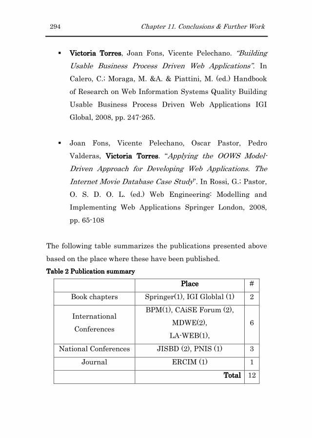
294 Chapter 11. Conclusions & Further Work
� Victoria TorresVictoria TorresVictoria TorresVictoria Torres, Joan Fons, Vicente Pelechano. “Building
Usable Business Process Driven Web Applications”. In
Calero, C.; Moraga, M. &A. & Piattini, M. (ed.) Handbook
of Research on Web Information Systems Quality Building
Usable Business Process Driven Web Applications IGI
Global, 2008, pp. 247-265.
� Joan Fons, Vicente Pelechano, Oscar Pastor, Pedro
Valderas, Victoria TorresVictoria TorresVictoria TorresVictoria Torres. “Applying the OOWS Model-
Driven Approach for Developing Web Applications. The
Internet Movie Database Case Study”. In Rossi, G.; Pastor,
O. S. D. O. L. (ed.) Web Engineering: Modelling and
Implementing Web Applications Springer London, 2008,
pp. 65-108
The following table summarizes the publications presented above
based on the place where these have been published.
Table Table Table Table 2222 Publication summary Publication summary Publication summary Publication summary
PlacePlacePlacePlace #
Book chapters Springer(1), IGI Globlal (1) 2
International
Conferences
BPM(1), CAiSE Forum (2),
MDWE(2),
LA-WEB(1),
6
National Conferences JISBD (2), PNIS (1) 3
Journal ERCIM (1) 1
TotalTotalTotalTotal 12

Appendix A
12 Lybrary4U Case Study
This appendix presents the Lybrary4U case study focusing on
those parts related with pure navigation. Then, appendixes B and
C will extend this part to provide support for short and long-
running Business Processes.
This appendix is structured as follows. First of all, a textual
description of the case study is presented. Then, based on this
description, sections A.2 and A.3 present the domain represented
in the Structural and the Services models respectively. Once these
models are completed, sections A.4 and A.5 develop the User,
Navigation and Presentation models following the OOWS
approach. These three models define (1) the kind of users that are
going to use the application (and the inheritance relationships
between them), (2) the visibility over the system for each kind of
user defined in the user model and (3) the organization of the
contents defined in the Navigational model.
A.1 Description
The Library4U case study is a web application developed basically
to support the information system related with a library. However,
the library also provides its members with an on-line book store

296 Appendix A. Library4U Case Study
service that sends members the shopped books to the address
provided by the member.
Therefore, it is necessary to provide mechanisms that allow users
looking for information contained in the system (for the shake of
simplicity it has been reduced to Authors and Books). Moreover,
this search functional is extended depending on the privileges
granted to specific users. For this reason, there are three levels of
privileges, which are Members, Librarians and Secretary Staff.
Members reference the group of users that can borrow books from
the library and buy books from the on-line store. The Librarian
group characterizes the users that make effective the loan of a
particular book to a particular member. Finally, the Secretary
Staff refers to users that validate proposals made by members (i.e.
including into the library catalogue a particular book).
A.2 Structural Model
According to the two main objectives of the Library4U system
(books loan and books sale), Figure 12.1 shows the class diagram
that represents the structure of the system in terms of classes and
relationships. On the one hand, classes such as copy, loan or
member are clearly associated to the books loan objective. On the
other hand, classes such as ShoppingCart, Offer or itemProduct
are clearly associated to the books sale objective. In addition, the
class Book represents the main class of this diagram being
connected with most of the remainder classes.

Appendix A. Library4U Case Study 297
Figure 12.1 Library4U Class Diagram
The class Book includes the following attributes: title, isbn,
editorial, number of edition, year of publication, price, stock and
asin (Amazon identifier number). This latter identifier number is
kept as book data since is going to be used for retrieving data from
the Amazon Web Service to complement the data that is kept in
the local Library4U database. Moreover, a book has been written
by many authors (represented by means of many-to-many
relationship between Book and Author classes) and it is
catalogued in many subjects (represented by means of many-to-
many relationship between Book and Subjects classes). The
library keeps several copies of the same book, being this
represented by the copy class (Copy) and the one-to-many
relationship. Then, book copies are loan to members in a
particular date, which is represented by the Loan class associated
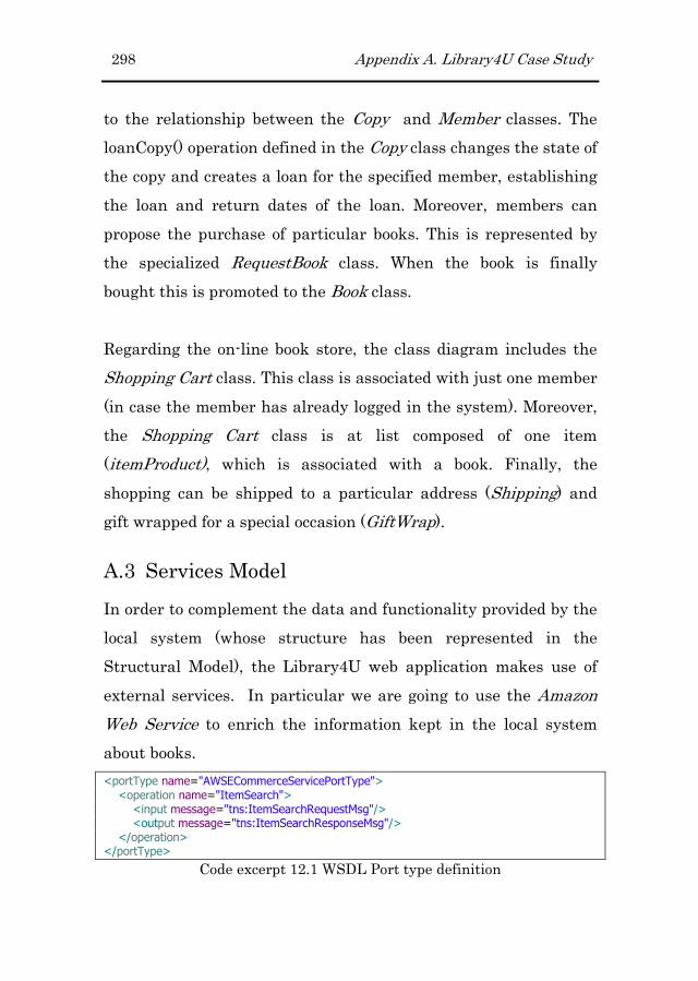
298 Appendix A. Library4U Case Study
to the relationship between the Copy and Member classes. The
loanCopy() operation defined in the Copy class changes the state of
the copy and creates a loan for the specified member, establishing
the loan and return dates of the loan. Moreover, members can
propose the purchase of particular books. This is represented by
the specialized RequestBook class. When the book is finally
bought this is promoted to the Book class.
Regarding the on-line book store, the class diagram includes the
Shopping Cart class. This class is associated with just one member
(in case the member has already logged in the system). Moreover,
the Shopping Cart class is at list composed of one item
(itemProduct), which is associated with a book. Finally, the
shopping can be shipped to a particular address (Shipping) and
gift wrapped for a special occasion (GiftWrap).
A.3 Services Model
In order to complement the data and functionality provided by the
local system (whose structure has been represented in the
Structural Model), the Library4U web application makes use of
external services. In particular we are going to use the Amazon
Web Service to enrich the information kept in the local system
about books.
<portType name="AWSECommerceServicePortType"> <operation name="ItemSearch"> <input message="tns:ItemSearchRequestMsg"/> <output message="tns:ItemSearchResponseMsg"/> </operation> </portType>
Code excerpt 12.1 WSDL Port type definition

Appendix A. Library4U Case Study 299
From the set of services provided by the Amazon Web Service we
are going to make use of the ItemSearch operation (see Code
excerpt 12.1). This operation returns items that satisfy the
specified search criteria. We are going to provide as search criteria
the book title kept in our system. This corresponds to one of the
elements defined in the request type of the ItemSearch operation
(see Code excerpt 12.2).
<xs:element name="ItemSearch"> <xs:complexType> <xs:sequence> <xs:element name="MarketplaceDomain" type="xs:string" minOccurs="0"/> <xs:element name="AWSAccessKeyId" type="xs:string" minOccurs="0"/> <xs:element name="SubscriptionId" type="xs:string" minOccurs="0"/> <xs:element name="AssociateTag" type="xs:string" minOccurs="0"/> <xs:element name="XMLEscaping" type="xs:string" minOccurs="0"/> <xs:element name="Validate" type="xs:string" minOccurs="0"/> <xs:element name="Shared" type="tns:ItemSearchRequest" minOccurs="0"/> <xs:element name="Request" type="tns:ItemSearchRequest" minOccurs="0" maxOccurs="unbounded"/> </xs:sequence> </xs:complexType> </xs:element> <xs:complexType name="ItemSearchRequest"> <xs:sequence> … <xs:element name="Title" type="xs:string" minOccurs="0"/> … </xs:sequence> </xs:complexType>
Code excerpt 12.2 ItemSearch Data Type
A.4 User Model
The kinds of users that can interact with the system are four,
which are categorized into two groups, one related to users that do
not have to be logged into the system (depicted in Figure 12.2 with
the “?” symbol) and another related to users that have to be logged
into the system (depicted in Figure 12.2 with the lock symbol). The
Anonymous user type has been included within the first group.

300 Appendix A. Library4U Case Study
Normally, the visibility of the system for this kind of users is quite
limited. Within the second group the Member, Librarian and
Secretary user types have been defined.
Figure 12.2 User Model
Moreover, all these kinds of users are connected through
inheritance relationships which allow propagating characteristics
(in particular navigational characteristics) from parents to
children.
The following section presents the Navigational Model defined for
each kind of user depending on their responsibilities.
A.5 Anonymous Navigational and Presentation
Model
This section present the Navigational and Presentation Models
defined for the Anonymous type of user identified in the User
Model. Attending to the two steps in which the Navigational
model is built first of all a global description of the navigation is
performed (the Authoring-in-the-large). Then, a detailed
description of the navigation is performed (Authoring-in-the-
small).

Appendix A. Library4U Case Study 301
A.5.1A.5.1A.5.1A.5.1 AuthoringAuthoringAuthoringAuthoring----inininin----thethethethe----largelargelargelarge
The Navigational Map for the Anonymous user is made up of four
navigational contexts providing each of them a different view over
the class diagram (see Figure 12.3).
Figure 12.3 Anonymous User Navigational Map
The “Home” navigational context has been designed to show the
new book purchases and also the available offers. The “H” label
included in the navigational link indicates that the target
navigational context is defined as the default context
(understanding default as home content). The “ShoppingCart”
navigational context shows to the user the state of her shopping
cart. It displays the books included in it, as well as the number of
units and the price of each book. The “Books” and “Authors”
navigational contexts allow the user searching for a particular
book and author respectively.
All these navigational contexts have been defined as Exploration
contexts. This means that anonymous users will be able to reach
any of them from any part of the web application. Moreover, the
Books and Authors contexts are connected through navigational

302 Appendix A. Library4U Case Study
links (solid arrows in Figure 12.3). This connection allows
propagating info that is used during the data retrieval of the
target context. As a result, the target context will show
information related with the received object.
A.5.1.1A.5.1.1A.5.1.1A.5.1.1 AuthoringAuthoringAuthoringAuthoring----inininin----thethethethe----smallsmallsmallsmall
Home Navigational ContextHome Navigational ContextHome Navigational ContextHome Navigational Context
The “Home” navigational context (see Figure 12.4) has been
defined to provide the user with information about (1) the new
books that have been purchased during the last month and (2) the
available book offers. This information is provided in two different
AIUs as it is shown in Figure 12.4.
Figure 12.4 Home Navigational Context
The Home context includes views over the Structural model (class
views defined over the Offer, Book and Copy classes) and the
Services model (a service-data-view defined over the AmazonAWS
web service). In addition, by means of the Context relationships
associated to the Copy and Offer views (solid arrows) we are

Appendix A. Library4U Case Study 303
defining a navigation capability to the Books context. The Offer
and the Copy class views include both a population filter. The
Offer class view retrieves just those offers that are still valid. On
the other hand, the Copy class view retrieves just the copies whose
purchase date is later than the specified date (Today() is a local
function that returns a particular date depending on the passed
arguments. If no arguments are provided, the function returns the
current date. On the contrary, the current date is incremented or
decremented with the provided parameters).
Once the navigational context has been defined we can proceed to
specify the presentation requirements. Figure 12.5 shows how the
elements defined in the navigational contexts are attached with
some properties regarding presentation issues. This information
states the way the data is going to be organized within the
graphical space according to the layout, order criteria, pagination
and occurrence order patterns.
Figure 12.5 Home Navigational Context (Presentation proprieties)
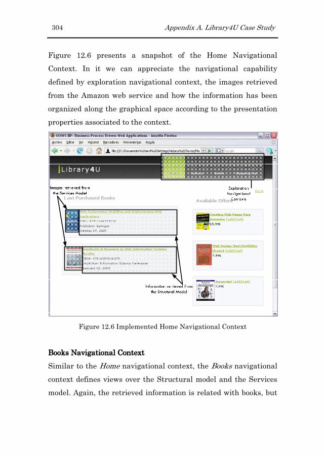
304 Appendix A. Library4U Case Study
Figure 12.6 presents a snapshot of the Home Navigational
Context. In it we can appreciate the navigational capability
defined by exploration navigational context, the images retrieved
from the Amazon web service and how the information has been
organized along the graphical space according to the presentation
properties associated to the context.
Figure 12.6 Implemented Home Navigational Context
Books Books Books Books Navigational ContextNavigational ContextNavigational ContextNavigational Context
Similar to the Home navigational context, the Books navigational
context defines views over the Structural model and the Services
model. Again, the retrieved information is related with books, but

Appendix A. Library4U Case Study 305
in this case, the class view does not define any population filter
(see Figure 12.7).
Figure 12.7 Books Navigational Context
In this case, the AIU defines an index (see bottom section of the
AIU Books) which gets activated when no data is passed to the
unit. This mechanism avoids overloading the web interfaces with
too much data. For instance, when the Books context is achieved
by means of the exploration context, the context retrieves all the
book instances displaying just the information that is indicated in
the index. Then, if an object of the recently obtained set is selected
(by means of the anchor attribute Book.title), the context will be
rendered but now with all the information defined in it.

306 Appendix A. Library4U Case Study
Related to presentation requirements, Figure 12.8 shows the
presentation attributes specified to the navigational elements.
Figure 12.8 Books Navigational Context (Presentation proprieties)
Figure 12.9 and Figure 12.10 correspond to the Book context in
both cases, when the index gets activated (Figure 12.9) and when
the context is passed with an object reference (Figure 12.10).

Appendix A. Library4U Case Study 307
Figure 12.9 Anonymous Book Navigational Context
Each book item shown in Figure 12.9 allows navigating either to
the details of the item book or to its authors (this is possible since
we have associated a context relationship between the book and
the author views).

308 Appendix A. Library4U Case Study
Figure 12.10 Anonymous Book Navigational Context (Detail)
Authors Authors Authors Authors Navigational ContextNavigational ContextNavigational ContextNavigational Context
From the Authors Navigational Context, the anonymous user can
get information about authors and their related books. Figure
12.11 and Figure 12.12 shows the navigational and presentation
details defined for this context.

Appendix A. Library4U Case Study 309
Figure 12.11 Authors Navigational
Context
Figure 12.12 Authors Navigational
Context (Presentation proprierties)
Figure 12.13 shows the implementation of the Authors
Navigational Context. In this case, as we have defined only two
attributes associated to the included view, it is not necessary to
define an index.
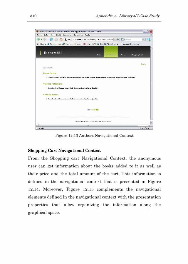
310 Appendix A. Library4U Case Study
Figure 12.13 Authors Navigational Context
Shopping Cart Shopping Cart Shopping Cart Shopping Cart NavigaNavigaNavigaNavigational Contexttional Contexttional Contexttional Context
From the Shopping cart Navigational Context, the anonymous
user can get information about the books added to it as well as
their price and the total amount of the cart. This information is
defined in the navigational context that is presented in Figure
12.14. Moreover, Figure 12.15 complements the navigational
elements defined in the navigational context with the presentation
properties that allow organizing the information along the
graphical space.
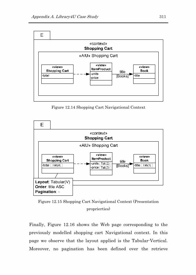
Appendix A. Library4U Case Study 311
Figure 12.14 Shopping Cart Navigational Context
Figure 12.15 Shopping Cart Navigational Context (Presentation
proprierties)
Finally, Figure 12.16 shows the Web page corresponding to the
previously modelled shopping cart Navigational context. In this
page we observe that the layout applied is the Tabular-Vertical.
Moreover, no pagination has been defined over the retrieve

312 Appendix A. Library4U Case Study
instances. Therefore, all instances are going to be included in a
unique block.
Figure 12.16 Shopping Cart Web page

Appendix B
B Short-running BP Case Study
This appendix extends the Library4U case study presented
previously to give support for a short-running BP. Therefore, a
description about the new requirement is presented in section B.1.
Then, from section B.2 to section B.5, the Structural Model,
Services Model, Business Process Model and Navigational Models
are developed to deal with the modelling step of the presented
short-running BP. Finally, section B.6 presents how usability
issues have been considered for this kind of BP.
B.1 Description
The checkout BP is usually found in Web sites that sell products
or services to their customers (sites commonly known as on-line
stores). Basically, this process consist of four activities, three
requiring interaction with the user (payment options, shipping
address details and gift wrapping) and one that is performed
completely by the system (placing the order). This BP has been
classified as a short-running BP because satisfies all the
characteristics found by this kind of BPs: it involves just one
human participant (in this case this refers to the customer) who
launches an instance of the BP. Moreover, the BP includes also

314 Appendix B. Short-running BP Case Study
collaboration with an external system which charges the shopping
to the customer account.
B.2 Structural Model
The part of the Structural model related to the Checkout BP is the
one presented in Figure 12.1. This model just includes the
operations that are invoked by the BPEL process in order to
perform a specific task.
+addToShoppingCart()
-title
-isbn
-editorial
-num_edition
-publish_date
-asin
-price
-stock
Book
Author
1..*
1..*
+liberate_sanction()
+sanction_member()
-dni
-name
-surname
-is_sanctioned
-login
-password
Member
-date
-total
ShoppingCart
0..*
0..*
-units
-price
itemProduct
0..* 1
0..10..1
+addToShoppingCart()
-from_date
-to_date
-description
-price
-valid
Offer
1
1..*
+createShipping()
-address
-city
-postal_code
-country : Country
-telephone
-delivery_date
Shipping
1
0..1
+setWrapOptions()
-ocasion : ocasion_types
-message
GiftWrap
+Birthday
+Friends
+Love
+Birth
«enumeration»
ocasion_types
10..1
+Afghanistan
+Albania
+Algeria
+Andorra
+Angola
+Antigua & Barbuda
+Argentina
+Armenia
+Australia
+Austria
+Azerbaijan
+Bahamas
+Bahrain
+Bangladesh
+Barbados
+Belarus
+...
«enumeration»
Country
Editor
1..*
1..*
-id
-name
Person
Figure B.1 Structural Model
B.3 Services Model
The set of services that are going to be consumed in the current
BP involves just one partner which represents a service providing
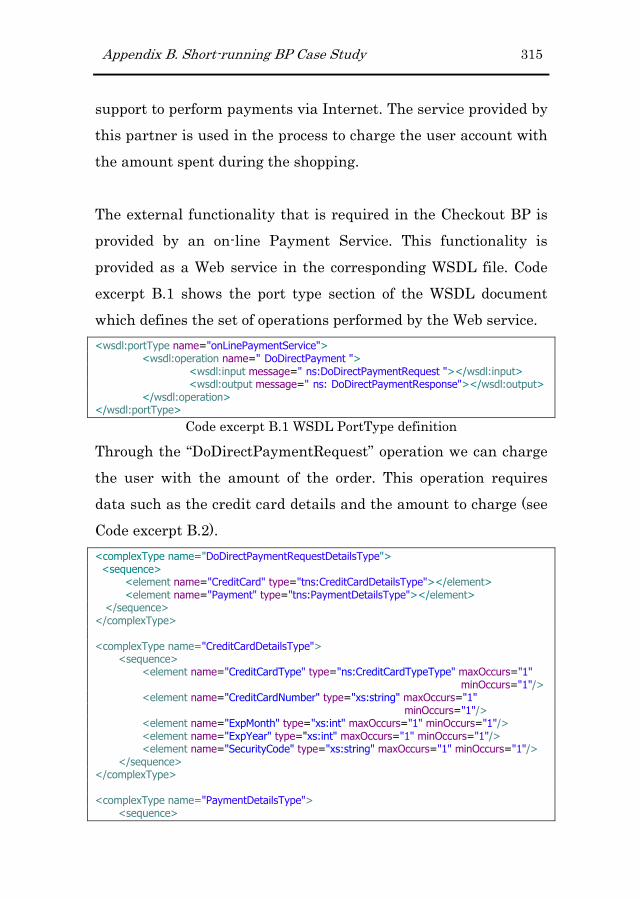
Appendix B. Short-running BP Case Study 315
support to perform payments via Internet. The service provided by
this partner is used in the process to charge the user account with
the amount spent during the shopping.
The external functionality that is required in the Checkout BP is
provided by an on-line Payment Service. This functionality is
provided as a Web service in the corresponding WSDL file. Code
excerpt B.1 shows the port type section of the WSDL document
which defines the set of operations performed by the Web service.
<wsdl:portType name="onLinePaymentService"> <wsdl:operation name=" DoDirectPayment "> <wsdl:input message=" ns:DoDirectPaymentRequest "></wsdl:input> <wsdl:output message=" ns: DoDirectPaymentResponse"></wsdl:output> </wsdl:operation> </wsdl:portType>
Code excerpt B.1 WSDL PortType definition
Through the “DoDirectPaymentRequest” operation we can charge
the user with the amount of the order. This operation requires
data such as the credit card details and the amount to charge (see
Code excerpt B.2).
<complexType name="DoDirectPaymentRequestDetailsType"> <sequence> <element name="CreditCard" type="tns:CreditCardDetailsType"></element> <element name="Payment" type="tns:PaymentDetailsType"></element> </sequence> </complexType> <complexType name="CreditCardDetailsType"> <sequence> <element name="CreditCardType" type="ns:CreditCardTypeType" maxOccurs="1" minOccurs="1"/> <element name="CreditCardNumber" type="xs:string" maxOccurs="1" minOccurs="1"/> <element name="ExpMonth" type="xs:int" maxOccurs="1" minOccurs="1"/> <element name="ExpYear" type="xs:int" maxOccurs="1" minOccurs="1"/> <element name="SecurityCode" type="xs:string" maxOccurs="1" minOccurs="1"/> </sequence> </complexType> <complexType name="PaymentDetailsType"> <sequence>

316 Appendix B. Short-running BP Case Study
<element name="OrderTotal" type="ns:string" maxOccurs="1" minOccurs="1"/> <element name="ItemTotal" type="xs:string" maxOccurs="1" minOccurs="1"/> <element name="ShippingTotal" type="xs:string" maxOccurs="1" minOccurs="1"/> </sequence> </complexType>
Code excerpt B.2 Data types used by the “DoDirectPayment” operation
B.4 Business Process Model
The BP defined in this case is made up of two entities, one
referring to the Library4U Company (the internal system) and
another referring to the payment service (provided by an external
system).
Valid?
No
Yes
«system»
Place Order
«user»
Shipping
«user»
Payment
«user»
Gift wrap
Figure B.2 Business Process Model
Moreover, within the internal system we distinguish two roles, the
human participant (being represented by the member) and the
system, referring this latter to the functionality that is provided
by the internal system and that do not requires interaction with
the user.
B.5 Navigational Model
This section presents the navigational model defined for the
member user.

Appendix B. Short-running BP Case Study 317
B.5.1B.5.1B.5.1B.5.1 AuthoringAuthoringAuthoringAuthoring----inininin----thethethethe----largelargelargelarge
The only navigational capability that we want to add to the
Navigational Model inherited from the anonymous user is the
possibility of proceeding with the check out of the shopping cart.
For this reason, as Figure B.3 shows, we have added just one
Process Context which represents the entry point to the process.
Figure B.3 Registered User Navigational Map
This Process Context has been defined as Exploration Context in
order to make it accessible to the user from any part of the
application. The details of this context are presented in the
following subsection.
B.5.2B.5.2B.5.2B.5.2 AuthoringAuthoringAuthoringAuthoring----inininin----thethethethe----smallsmallsmallsmall
The Checkout Process Context, as Figure B.4 shows, includes
three Activity Containers (one per each activity requiring
interaction with the user, see Member lane within the Library4U
pool in Figure B.2).

318 Appendix B. Short-running BP Case Study
Figure B.4 Checkout Navigational Context
From the set of Activity Containers included in the Checkout
process context, two include views over classes defined in the
Structural model (the Shipping and Gift wrap activity containers)
and one defines a view over a service from the Services model (the
Payment activity container). In this case, all the containers are
used to gather data from the user and no additional information is
shown to the user. Figure B.5, Figure B.6 and Figure B.7 show
respectively the Web pages equivalent to the activity containers
included in the Checkout Process Context.
In these figures we have stressed four areas which correspond to
(A) the set of tasks that has to be completed by the user in order to
complete the process, (B) the entry point to the process (the
context was defined as exploration), (C) the label indicating the
task being performed at each moment and (D) the area provided to
the user to introduce the information required to accomplish the
current activity.
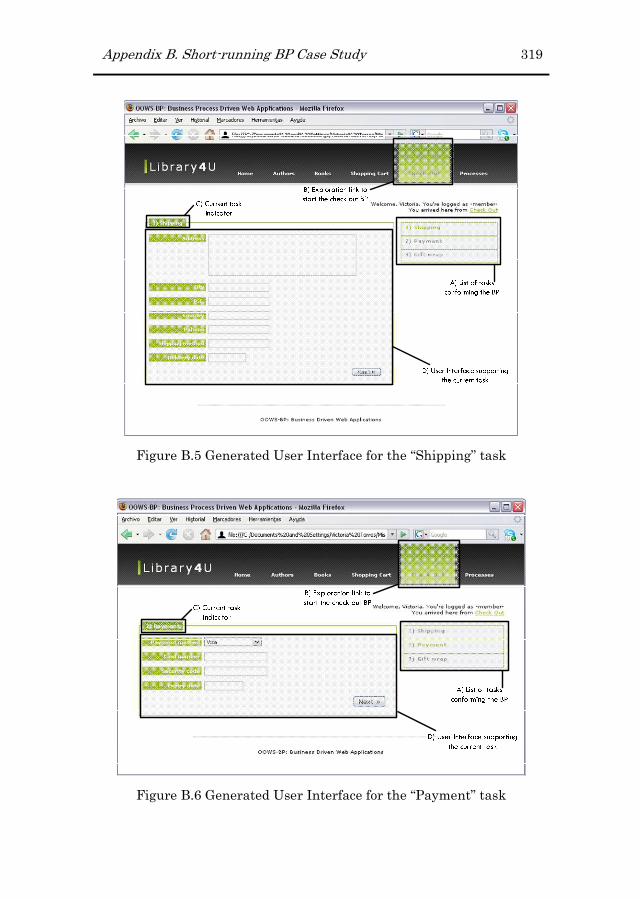
Appendix B. Short-running BP Case Study 319
Figure B.5 Generated User Interface for the “Shipping” task
Figure B.6 Generated User Interface for the “Payment” task

320 Appendix B. Short-running BP Case Study
Figure B.7 Generated User Interface for the “Gift wrap” task
B.6 Usability Aspects
The application of a set of usability guidelines during the
transformation process ensures the production of usable web
applications. For instance, in this case, as the current case study
deals with a short-running process, the generated user interfaces
include the wizard pattern. This pattern can be seen in Figure B.5,
Figure B.6 and Figure B.7 in the remarked area labelled with an
“A” and allow displaying the user the set of tasks that made up
the process. Moreover, an indicator of the current task is also
included in the interface (see the remarked area labelled with a
“C” and also the colour of the corresponding task in the wizard in
Figure B.5, Figure B.6 and Figure B.7).
Appendix C
C Long-running BP Case Study
This appendix extends the case study presented in appendix A
with a long-running process. In particular the extension deals
with the Book Request Purchase BP (hereafter BRP-BP) which is
presented in detail in the first subsection. The remainder of the
appendix is structured as follows. Section C.2 rescues those parts
from the structural model presented in appendix A that are
related with the applicable BP. Section C.3 extends the Services
Model with the service and operations related to the BPR-BP.
Then, section C.4 presents the Business Process Diagram
representing the BRP-BP. Finally, section C.5 develops the
Navigational and Presentation models for the registered users
modelled in the User Model in Appendix A.
C.1 Description
The BRP-BP is a kind of process quite common in any
organization. This kind of processes basically consists in three
steps which are (1) someone applying for something (i.e. a
certificate, a service, a good, etc.) (2) someone validating the
application and (3) in case the validation was positive, provide the

322 Appendix C. Long-running BP Case Study
applicant with the requested thing. In this process, during the last
two steps more than one person or service can be involved.
In particular, the present case study deals with the purchase and
later loan of a book that is not in the library. The request is
launched by a member of the library, validated by the secretary
staff of the library based on a particular criterion, purchased by
the central library (an external system), and finally loan by the
librarian staff.
This BP has been classified as a long-running BP because satisfy
all the characteristics found by this kind of BPs. Multiple human
participants, corresponding to different roles within the
organization, are involved in the BP. Moreover, the BP includes
also collaboration with an external system which performs the
book purchase.
C.2 Structural Model
The excerpt of the structural model presented in this section
includes all the classes that are related to the RBP-BP. These
classes define the operations that are going to be associated to the
activities that make up the process.
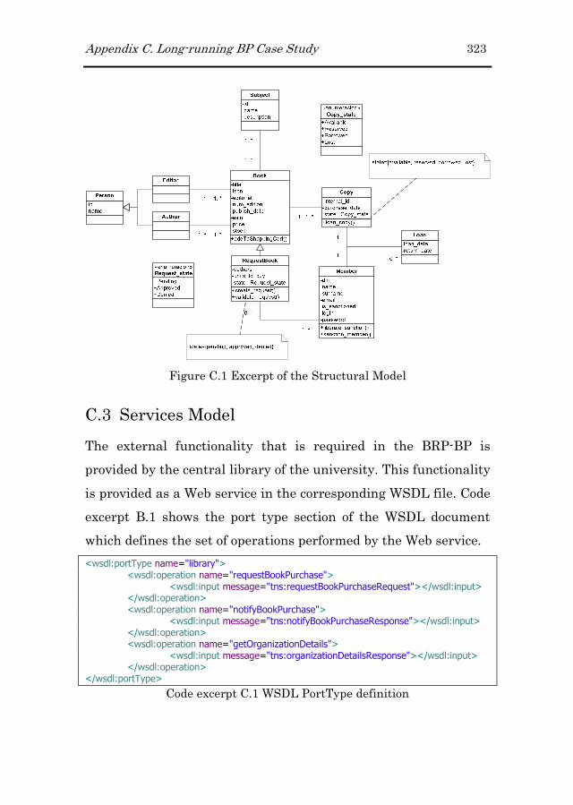
Appendix C. Long-running BP Case Study 323
Figure C.1 Excerpt of the Structural Model
C.3 Services Model
The external functionality that is required in the BRP-BP is
provided by the central library of the university. This functionality
is provided as a Web service in the corresponding WSDL file. Code
excerpt B.1 shows the port type section of the WSDL document
which defines the set of operations performed by the Web service.
<wsdl:portType name="library"> <wsdl:operation name="requestBookPurchase"> <wsdl:input message="tns:requestBookPurchaseRequest"></wsdl:input> </wsdl:operation> <wsdl:operation name="notifyBookPurchase"> <wsdl:input message="tns:notifyBookPurchaseResponse"></wsdl:input> </wsdl:operation> <wsdl:operation name="getOrganizationDetails"> <wsdl:input message="tns:organizationDetailsResponse"></wsdl:input> </wsdl:operation> </wsdl:portType>
Code excerpt C.1 WSDL PortType definition

324 Appendix C. Long-running BP Case Study
The “requestBookPurchase” operation allows us notifying the
central library about the necessity of buying a particular book.
This operation requires some data about the book requested such
as its “isbn” or “title” (see Code excerpt B.2).
<complexType name="book"> <sequence> <choice> <sequence> <element name="isbn" type="string" maxOccurs="1" minOccurs="1" /> <element name="title" type="string" maxOccurs="1" minOccurs="0" /> </sequence> <sequence> <element name="isbn" type="string" maxOccurs="1" minOccurs="0" /> <element name="title" type="string" maxOccurs="1" minOccurs="1" /> </sequence> </choice> <element name="author" type="string" maxOccurs="1" minOccurs="0" /> <element name="year" type="string" maxOccurs="1" minOccurs="0" /> </sequence> </complexType> <element name="book" type="tns:book" /> <complexType name="bookRequest"> <sequence> <element name="requestNumber" type="tns:requestNumber" /> <element name="requester" type="tns:requester" /> <element name="book" type="tns:book" /> </sequence> </complexType>
Code excerpt C.2 Message type required by “requestBookPurchase”
operation
C.4 Business Process Model
The Business Process Model allows defining the set of activities
that have to be performed in order to buy and loan a particular
book. Moreover, it allows distributing these activities among the
involved participants, being these humans or systems.
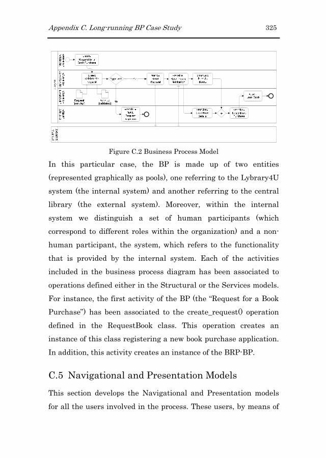
Appendix C. Long-running BP Case Study 325
Figure C.2 Business Process Model
In this particular case, the BP is made up of two entities
(represented graphically as pools), one referring to the Lybrary4U
system (the internal system) and another referring to the central
library (the external system). Moreover, within the internal
system we distinguish a set of human participants (which
correspond to different roles within the organization) and a non-
human participant, the system, which refers to the functionality
that is provided by the internal system. Each of the activities
included in the business process diagram has been associated to
operations defined either in the Structural or the Services models.
For instance, the first activity of the BP (the “Request for a Book
Purchase”) has been associated to the create_request() operation
defined in the RequestBook class. This operation creates an
instance of this class registering a new book purchase application.
In addition, this activity creates an instance of the BRP-BP.
C.5 Navigational and Presentation Models
This section develops the Navigational and Presentation models
for all the users involved in the process. These users, by means of

326 Appendix C. Long-running BP Case Study
the inheritance relationship, extend the navigational map defined
for the anonymous user presented in the appendix A. Again, the
following subsections are going to be organized in two parts
attending to the two steps in which the Navigational model is built
(Authoring-in-the-large and Authoring-in-the-small).
C.5.1C.5.1C.5.1C.5.1 Member Navigational Member Navigational Member Navigational Member Navigational and Presentation and Presentation and Presentation and Presentation ModelModelModelModel
C.5.1.1C.5.1.1C.5.1.1C.5.1.1 AuthoringAuthoringAuthoringAuthoring----inininin----thethethethe----largelargelargelarge
Since the member user is involved in the BRP-BP, a new context
is added into her Navigational map. However, in this case the
context refers to a process context. This new context extends the
navigational map inherited from the anonymous user. Figure C.3
depicts the Navigational Map for the member user. When the
inherited contexts are not modified it is not necessary to include
them in the map again.
Figure C.3 Member Navigational Map
This process context has been defined as Exploration Context
(context labelled with an “E” in Figure C.3) in order to make it
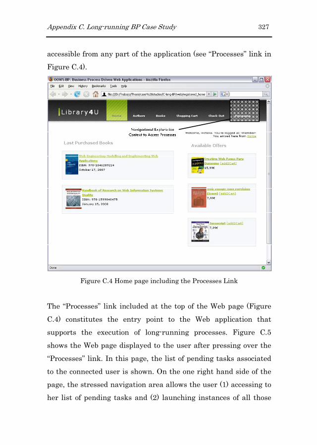
Appendix C. Long-running BP Case Study 327
accessible from any part of the application (see “Processes” link in
Figure C.4).
Figure C.4 Home page including the Processes Link
The “Processes” link included at the top of the Web page (Figure
C.4) constitutes the entry point to the Web application that
supports the execution of long-running processes. Figure C.5
shows the Web page displayed to the user after pressing over the
“Processes” link. In this page, the list of pending tasks associated
to the connected user is shown. On the one right hand side of the
page, the stressed navigation area allows the user (1) accessing to
her list of pending tasks and (2) launching instances of all those
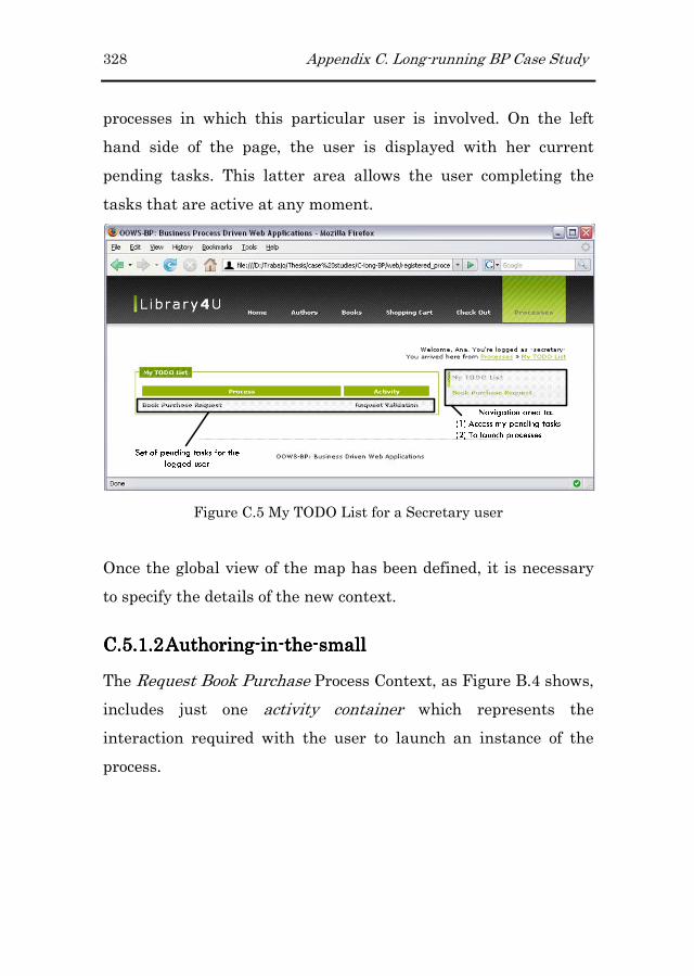
328 Appendix C. Long-running BP Case Study
processes in which this particular user is involved. On the left
hand side of the page, the user is displayed with her current
pending tasks. This latter area allows the user completing the
tasks that are active at any moment.
Figure C.5 My TODO List for a Secretary user
Once the global view of the map has been defined, it is necessary
to specify the details of the new context.
C.5.1.2C.5.1.2C.5.1.2C.5.1.2 AuthoringAuthoringAuthoringAuthoring----inininin----thethethethe----smallsmallsmallsmall
The Request Book Purchase Process Context, as Figure B.4 shows,
includes just one activity container which represents the
interaction required with the user to launch an instance of the
process.
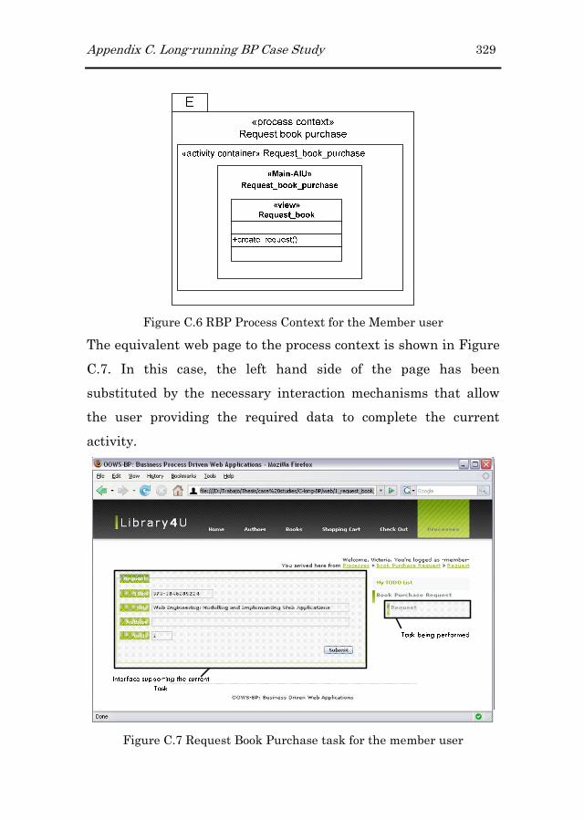
Appendix C. Long-running BP Case Study 329
Figure C.6 RBP Process Context for the Member user
The equivalent web page to the process context is shown in Figure
C.7. In this case, the left hand side of the page has been
substituted by the necessary interaction mechanisms that allow
the user providing the required data to complete the current
activity.
Figure C.7 Request Book Purchase task for the member user

330 Appendix C. Long-running BP Case Study
In this case, since the task simply involves the introduction of
some data from the user, it is not necessary the application of any
presentation pattern. For this reason the definition of
presentation requirements is skipped for this process context.
C.5.2C.5.2C.5.2C.5.2 Secretary Navigational ModelSecretary Navigational ModelSecretary Navigational ModelSecretary Navigational Model
C.5.2.1C.5.2.1C.5.2.1C.5.2.1 AuthoringAuthoringAuthoringAuthoring----inininin----thethethethe----largelargelargelarge
Similarly to the member user, the navigational map of the
secretary user includes a process context associated to the BRP-
BP. However, since we defined a inheritance relationship between
the member and the secretary user types, in this case the process
context is going to be redefined from the one inherited from the
member user (see Figure C.8).
Figure C.8 Secretary User Navigational Map
The redefinition of this context is presented in the following
subsection.
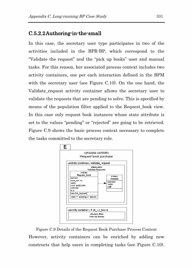
Appendix C. Long-running BP Case Study 331
C.5.2.2C.5.2.2C.5.2.2C.5.2.2 AuthoringAuthoringAuthoringAuthoring----inininin----thethethethe----smallsmallsmallsmall
In this case, the secretary user type participates in two of the
activities included in the BPR-BP, which correspond to the
“Validate the request” and the “pick up books” user and manual
tasks. For this reason, her associated process context includes two
activity containers, one per each interaction defined in the BPM
with the secretary user (see Figure C.10). On the one hand, the
Validate_request activity container allows the secretary user to
validate the requests that are pending to solve. This is specified by
means of the population filter applied to the Request_book view.
In this case only request book instances whose state attribute is
set to the values “pending” or “rejected” are going to be retrieved.
Figure C.9 shows the basic process context necessary to complete
the tasks committed to the secretary role.
Figure C.9 Details of the Request Book Purchase Process Context
However, activity containers can be enriched by adding new
constructs that help users in completing tasks (see Figure C.10).

332 Appendix C. Long-running BP Case Study
In particular, the Validate_request activity container has been
enriched with two complementary AIUs. These AIUs add some
useful information to help the user in the decision of validating or
rejecting the requests. In this case the Last Purchases
Complementary AIU shows the user the book copies that have
been purchased in the last month. On the other hand, the
Sanctioned Members Complementary-AIU shows the department
members that are sanctioned and that cannot apply for any book
purchase.
Figure C.10 RBP Process Context for the Secretary user
In addition, to avoid overloading the user interface with too many
information related to book requests, we have also introduced an
index. In this case, when the index gets activated just the

Appendix C. Long-running BP Case Study 333
attributes specified in the index definition are going to be
displayed (see Figure C.11).
In this case, we are going to specify a presentation requirement
associated to the “Validate_request” activity container. We want to
handle multiple request instances at the same time. For this
reason we have associated the List builder pattern to the activity
container.
Figure C.11 RBP Process Context for the Secretary user (Presentation
properties)
The application of this pattern allows the user solving multiple
activity instances at the same time (see Figure C.12). The
application of this pattern allows reducing the time invested in
some tasks as well as improving the user experience by avoid the
user completing each activity instance one by one. However, the
application of this pattern does not mean that the user cannot

334 Appendix C. Long-running BP Case Study
proceed with each activity instance separately. In fact, this
possibility is still provided to the user. In fact, by selecting the
title of the book she can retrieve all the data associated to the
particular activity instance.
Figure C.12 List Build pattern applied to the Request Validation Activity
Container
In addition, the Detail On Demand pattern has also been applied
(see Figure C.13). In this case we have used this pattern to display
more data related to a particular activity instance but without
leaving the current page. This information is contained in the
page but only shown when the cursor is positioned over the title
link.
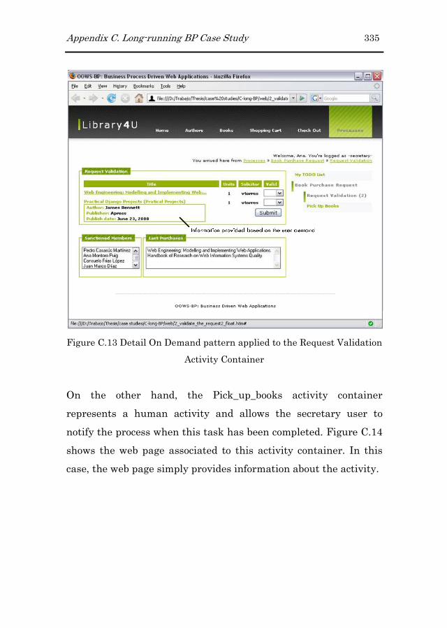
Appendix C. Long-running BP Case Study 335
Figure C.13 Detail On Demand pattern applied to the Request Validation
Activity Container
On the other hand, the Pick_up_books activity container
represents a human activity and allows the secretary user to
notify the process when this task has been completed. Figure C.14
shows the web page associated to this activity container. In this
case, the web page simply provides information about the activity.

336 Appendix C. Long-running BP Case Study
Figure C.14 Generated interface for the “Pick Up Books” activity
C.5.3C.5.3C.5.3C.5.3 Librarian Navigational ModeLibrarian Navigational ModeLibrarian Navigational ModeLibrarian Navigational Modellll
C.5.3.1C.5.3.1C.5.3.1C.5.3.1 AuthoringAuthoringAuthoringAuthoring----inininin----thethethethe----largelargelargelarge
Similarly to the secretary user type, the librarian inherits the
navigational map defined for the member user type. Therefore, in
this case we have to redefine the inherited process context as
Figure C.15 shows.
Figure C.15 Librarians Navigational Map

Appendix C. Long-running BP Case Study 337
C.5.3.2C.5.3.2C.5.3.2C.5.3.2 AuthoringAuthoringAuthoringAuthoring----inininin----thethethethe----smallsmallsmallsmall
In this case, the librarian user type has only one responsibility
regarding the BPR-BP. This activity is related with the loan event
where the system registers that this book copy has been lent to a
particular user. For this reason, the Loan_book activity container
includes the loan_copy operation of the copy class (see Figure
C.16).
«process context»
Request book purchase
«activity container» Loan_book
«Main-AIU»
Loan_book
+loan_copy()
«view»
Copy
E
Figure C.16 Loan book Navigational Context
In this case, the librarian user is simply asked for certifying that
the loan has been performed. For this reason the generated web
interface associated to this activity container simply shows the
information associated to the loan transaction which is the book
copy and the applicant member (see Figure C.17).

338 Appendix C. Long-running BP Case Study
Figure C.17 Generated interface for the “Loan Book” activity
References
Abran, A., Khelifi, A., Suryn, W., & Seffah, A. (2003). Usability
meanings and interpretations in iso standards. Software
Quality Journal, 11(4), 325–338.
Agrawal, A., Amend, M., Das, M., Ford, M., Keller, C.,
Kloppmann, M., König, D., Leymann, F., Müller, R., Pfau, G.,
Plösser, K., Rangaswamy, R., Rickayzen, A., Patrick Schmidt,
M. R., Trickovic, I., Yiu, A., & Matthias, Z. (2007a). Ws-
humantask v1.0. Active Endpoints, Adobe, BEA Systems,
IBM, Oracle and SAP AG.
Agrawal, A., Amend, M., Das, M., Ford, M., Keller, C.,
Kloppmann, M., König, D., Leymann, F., Müller, R., Pfau, G.,
Plösser, K., Rangaswamy, R., Rickayzen, A., Rowley, M.,
Schmidt, P., Trickovic, I., Yiu, A., & Zeller, M. (2007b).
Bpel4people v1.0. Active Endpoints, Adobe, BEA Systems,
IBM, Oracle and SAP AG.
Andrews, T., Curbera, F., Dholakia, H., Goland, Y., Klein, J.,
Leymann, F., Liu, K., Roller, D., Smith, D., Thatte, S.,
Trickovic, I., & Weerawarana, S. (2003). Business process
execution language for web services version 1.1.

340 References
Atterer, R., Schmidt, A., & Hußmann, H. (2006). Extending web
engineering models and tools for automatic usability
validation. J. Web Eng., 5(1), 43–64.
Benatallah, B., Casati, F., Grigori, D., Nezhad, H. R. M., &
Toumani, F. (2005). Developing adapters for web services
integration. In O. Pastor, & J. F. e Cunha (Eds.) CAiSE, vol.
3520 of Lecture Notes in Computer Science, (pp. 415–429).
Springer.
Berners-Lee, T. (1996). WWW: past, present, and future. 29, 69–
77.
Bozzon, A., Comai, S., Fraternali, P., & Carughi, G. T. (2006).
Conceptual modeling and code generation for rich internet
applications. In D. Wolber, N. Calder, C. Brooks, & A. Ginige
(Eds.) ICWE, (pp. 353–360). ACM.
Brambilla, M. (2003). Extending hypertext conceptual models with
process-oriented primitives. In I.-Y. Song, S. W. Liddle, T. W.
Ling, & P. Scheuermann (Eds.) ER, vol. 2813 of Lecture Notes
in Computer Science, (pp. 246–262). Springer.
Brambilla, M., Celino, I., Ceri, S., Cerizza, D., Valle, E. D., &
Facca, F. M. (2006a). A software engineering approach to
design and development of semantic web service applications.
In I. F. Cruz, S. Decker, D. Allemang, C. Preist, D. Schwabe,
P. Mika, M. Uschold, & L. Aroyo (Eds.) International
References 341
Semantic Web Conference, vol. 4273 of Lecture Notes in
Computer Science, (pp. 172–186). Springer.
Brambilla, M., Ceri, S., Comai, S., & Fraternali, P. (2006b). A case
tool for modelling and automatically generating web service-
enabled applications. Int. J. Web Eng. Technol., 2(4), 354–372.
Brambilla, M., Ceri, S., Comai, S., Fraternali, P., & Manolescu, I.
(2003). Specification and design of workflow-driven
hypertexts. In WWW (Posters).
Brambilla, M., Ceri, S., Fraternali, P., & Manolescu, I. (2006c).
Process modeling in web applications. ACM Trans. Softw.
Eng. Methodol., 15(4), 360–409.
Brambilla, M., Comai, S., Fraternali, P., & Matera, M. (2008). Web
Engineering: Modelling and Implementing Web Applications,
chap. Designing Web Applications with Webml and Webratio,
(pp. 221–261). Human-Computer Interaction Series. Springer
London.
Burstein, M., Hobbs, J., Lassila, O., Mcdermott, D., Mcilraith, S.,
Narayanan, S., Paolucci, M., Parsia, B., Payne, T., Sirin, E.,
Srinivasan, N., & Sycara, K. (2004). Owl-s: Semantic markup
for web services. Website.

342 References
Cáceres, P., de Castro, V., & Marcos, E. (2004). Navigation
modelling from a user services oriented approach. In ADVIS,
(pp. 150–160).
Cachero, C., & Gómez, J. (2002). Advanced conceptual modeling of
web applications: Embedding operation interfaces in
navigation design. In M. Celma, O. Pastor, N. J. Juzgado, &
J. J. Moreno-Navarro (Eds.) JISBD, (pp. 235–248).
Casteleyn, S. (2005). Designer Specified Self Re-organizing
Websites,. Ph.D. thesis, Vrije Universiteit Brussel.
Ceri, S., Daniel, F., Facca, F. M., & Matera, M. (2007). Model-
driven engineering of active context-awareness. World Wide
Web, 10(4), 387–413.
Ceri, S., Fraternali, P., & Bongio, A. (2000). Web modeling
language (webml): a modeling language for designing web
sites. In Proceedings of the 9th international World Wide Web
conference on Computer networks : the international journal
of computer and telecommunications netowrking, (pp. 137–
157). Amsterdam, The Netherlands, The Netherlands: North-
Holland Publishing Co.
Cunin, P.-Y., Greenwood, R. M., Francou, L., Robertson, I., &
Warboys, B. (2001). The pie methodology - concept and
application. In V. Ambriola (Ed.) EWSPT, vol. 2077 of Lecture
Notes in Computer Science, (pp. 3–26). Springer.
References 343
Czarnecki, K., & Helsen, S. (2003). Classification of model
transformation approaches. In OOPSLA’03 Workshop on
Generative Techniques in the Context of Model-Driven
Architecture.
de Assis, P. S., Schwabe, D., & Nunes, D. A. (2006). Ashdm -
model-driven adaptation and meta-adaptation. In V. P. Wade,
H. Ashman, & B. Smyth (Eds.) AH, vol. 4018 of Lecture Notes
in Computer Science, (pp. 213–222). Springer.
Distante, D. (2004). Reengineering legacy applications and web
transactions: an extended version of the UWA transaction
design model. Ph.D. thesis, University of Lecce, Italy.
Distante, D., Rossi, G., & Canfora, G. (2007a). Modeling business
processes in web applications: an analysis framework. In
Y. Cho, R. L. Wainwright, H. Haddad, S. Y. Shin, & Y. W. Koo
(Eds.) SAC, (pp. 1677–1682). ACM.
Distante, D., Rossi, G., Canfora, G., & Tilley, S. R. (2007b). A
comprehensive design model for integrating business
processes in web applications. Int. J. Web Eng. Technol., 3(1),
43–72.
Fialho, A. T. S., & Schwabe, D. (2007). Enriching hypermedia
application interfaces. In L. Baresi, P. Fraternali, & G.-J.
Houben (Eds.) ICWE, vol. 4607 of Lecture Notes in Computer
Science, (pp. 188–193). Springer.
344 References
Firesmith, D. G., & Henderson-Sellers, B. (2001). The OPEN
Process Framework. Addison-Wesley Longman.
Fons, J. (2008). OOWS: A Model Driven Method for the
Development of Web Applications. Ph.D. thesis, Technical
University of Valencia.
Fons, J., Pelechano, V., Pastor, O., Valderas, P., & Torres, V.
(2008). Web Engineering: Modelling and Implementing Web
Applications, chap. Applying the OOWS Model-Driven
Approach for Developing Web Applications. The Internet
Movie Database Case Study, (pp. 65–108). Human-Computer
Interaction Series. Springer London.
Garrigós, I., Gomez, J., & Cachero, C. (2003). Modelling dynamic
personalization in web applications. In ICWE, (pp. 472–475).
Garzotto, F., & Perrone, V. (2007). Industrial acceptability of
design methods: an empirical study. Journal of Web
Engineering, 6, 73–96.
Ginige, A., & Murugesan, S. (2001a). Guest editors’ introduction:
The essence of web engineering-managing the diversity and
complexity of web application development. IEEE
MultiMedia, 8(2), 22–25.
References 345
Ginige, A., & Murugesan, S. (2001b). Guest editors’ introduction:
Web engineering an introduction. IEEE MultiMedia, 8(1), 14–
18.
Gómez, J., Cachero, C., & Pastor, O. (2000). Extending a
conceptual modelling approach to web application design. In
B. Wangler, & L. Bergman (Eds.) CAiSE, vol. 1789 of Lecture
Notes in Computer Science, (pp. 79–93). Springer.
Hollingsworth, D. (1995). The workflow reference model.
document number tc00-1003.
Hornung, T., Koschmider, A., & Oberweis, A. (2007). Rule-based
autocompletion of business process models. In CAiSE Forum.
Houben, G.-J. (2000). HERA: Automatically generating
hypermedia front-ends. In EFIS, (pp. 81–88).
Houben, G.-J., Barna, P., Frasincar, F., & Vdovjak, R. (2003).
Hera: Development of semantic web information systems. In
J. M. C. Lovelle, B. M. G. Rodríguez, L. J. Aguilar, J. E. L.
Gayo, & M. del Puerto Paule Ruíz (Eds.) ICWE, vol. 2722 of
Lecture Notes in Computer Science, (pp. 529–538). Springer.
Houben, G.-J., Frasincar, F., Barna, P., & Vdovjak, R. (2004).
Modeling user input and hypermedia dynamics in hera. In
N. Koch, P. Fraternali, & M. Wirsing (Eds.) ICWE, vol. 3140
of Lecture Notes in Computer Science, (pp. 60–73). Springer.

346 References
Houben, G.-J., van der Sluijs, K., Barna, P., Broekstra, J., , S. C.,
Fiala, Z., & Frasincar, F. (2008). Web Engineering: Modelling
and Implementing Web Applications, chap. HERA, (pp. 263–
301). Human-Computer Interaction Series. Springer London.
Jouault, F., & Kurtev, I. (2006). On the architectural alignment of
atl and qvt. In H. Haddad (Ed.) SAC, (pp. 1188–1195). ACM.
Kappel, G., Pröll, B., Reich, S., Retschitzegger, W., Grünbacher,
P., Schwinger, W., Koch, N., Eichinger, C., Austaller, G.,
Hartl, A., Lauff, M., Lyardet, F., Mühlhäuser, M.,
Nussbaumer, M., Gaedke, M., Steindl, C., Ramler, R.,
Altmann, J., Ebner, A., Pröll, B., Werthner, H., Mayr, H.,
Engels, G., Lohmann, M., Wagner, A., Hitz, M., Leitner, G.,
Melcher, R., Kotsis, G., Wimmer, M., Kemper, A., Seltzsam,
S., Behrendt, W., & Arora, N. (2006). Web Engineering. The
Discipline of Systematic Development of Web Applications.
John Wiley & Sons, Ltd.
Kloppmann, M., Koenig, D., Leymann, F., Pfau, G., Rickayzen, A.,
von Riegen, C., Schmidt, P., & Trickovic, I. (2005). Ws-bpel
extension for people – bpel4people.
Knapp, A., Koch, N., Zhang, G., & Hassler, H.-M. (2004). Modeling
business processes in web applications with argouwe. In
T. Baar, A. Strohmeier, A. M. D. Moreira, & S. J. Mellor (Eds.)
UML, vol. 3273 of Lecture Notes in Computer Science, (pp.
69–83). Springer.
References 347
Koch, N. (2001). Software Engineering for Adaptive Hypermedia
Systems: Reference Model, Modeling Techniques and
Development Process. Ph.D. thesis, Ludwig-Maximilians-
University Munich, Germany.
Koch, N. (2006). Transformation techniques in the model-driven
development process of uwe. In ICWE ’06: Workshop
proceedings of the sixth international conference on Web
engineering, (p. 3). New York, NY, USA: ACM.
Koch, N. (2007). Classification of model transformation techniques
used in uml-based web engineering. IET Software Journal,
1(3), 98–111.
Koch, N., Knapp, A., Zhang, G., & Baumeister, H. (2008). Web
Engineering: Modelling and Implementing Web Applications,
chap. Uml-Based Web Engineering, (pp. 157–191). Human-
Computer Interaction Series. Springer London.
Koch, N., & Kraus, A. (2002). The expressive power of uml-based
engineering. In Second International Workshop on Web
Oriented Software Techonlogy (CYTED), (pp. 105–119).
Koch, N., Kraus, A., Cachero, C., & Meliá, S. (2004). Integration of
business processes in web application models. J. Web Eng.,
3(1), 22–49.

348 References
Kraus, A., Knapp, A., & Koch, N. (2007). Model-driven generation
of web applications in uwe. In 3rd International Workshop on
Model-Driven Web Engineering. MDWE 2007 3rd
International Workshop on Model-Driven Web Engineering
(Proceedings) CEUR-WS, Vol 261, July 2007.
Lima, F., & Schwabe, D. (2003). Application modeling for the
semantic web. In Web Congress, 2003. Proceedings. First
Latin American, (pp. 93– 102).
Marcos, E., Cáceres, P., & Castro, V. D. (2004). An approach for
navigation model construction from the use cases model.
CAiSE Forum. Held in conjunction with the 16th Conference
On Advanced Information Systems Engineering.
Marcos, E., de Castro, V., & Vela, B. (2003a). Representing web
services with uml: A case study. In ICSOC, (pp. 17–27).
Marcos, E., Vela, B., & Cavero, J. M. (2003b). A methodological
approach for object-relational database design using uml.
Software and System Modeling, 2(1), 59–75.
Mayhew, D. J. (1992). Principles and guidelines in software user
interface design. Upper Saddle River, NJ, USA: Prentice-Hall,
Inc.
Mendes, E., & Mosley, N. (Eds.) (2006). Web Engineering.
Springer.

References 349
Miller, J., & Mukerji, J. (2003). MDA Guide Version 1.0.1. Tech.
Rep. omg/03-06-01, Object Management Group (OMG).
Murugesan, S., & Ginige, A. (2001). Web engineering: Introduction
and perspectives - overview. In S. Murugesan, &
Y. Deshpande (Eds.) Web Engineering, vol. 2016 of Lecture
Notes in Computer Science, (pp. 1–2). Springer.
Nielsen, J. (1999). Designing Web Usability. Peachpit Press.
OMG (2004). Unified modeling language specification: Version 2,
revised final adopted specification (ptc/04-10-02).
OMG (2005a). MOF QVT Final Adopted Specification.
OMG (2005b). Software process engineering metamodel
specification (SPEM), v1.1. Tech. rep., Object Manament
Group.
OMG (2006). Business process modeling notation (bpmn)
specification, omg final adopted specification. dtc/06-02-01.
OMG (2007a). Business process definition metamodel (bpdm), beta
1.
OMG (2007b). Business process model and notation (bpmn) 2.0
request for proposal, omg document: Bmi/2007-06-05.

350 References
Ouyang, C., van der Aalst, W. M., Dumas, M., & ter Hofstede,
A. H. (2006). From business process models to process-
oriented software systems: The bpmn to bpel way. Tech. rep.,
Queensland University of Technology.
Pastor, O., Gómez, J., Insfrán, E., & Pelechano, V. (2001). The OO-
method approach for information systems modeling: from
object-oriented conceptual modeling to automated
programming. Inf. Syst., 26(7), 507–534.
Paternò, F., Mancini, C., & Meniconi, S. (1997). Concurtasktrees:
A diagrammatic notation for specifying task models. In
INTERACT, (pp. 362–369).
Pressman, R. S., Lewis, T. G., Adida, B., Ullman, E., DeMarco, T.,
Gilb, T., Gorda, B. C., Humphrey, W. S., & Johnson, R. (1998).
Can internet-based applications be engineered? IEEE
Software, 15(5), 104–110.
Quintero, R. (2008). Desarrollo Dirigido por Modelos de
Aplicaciones Web que integran Datos y Funcionalidad a partir
de Servicios Web. Ph.D. thesis, Technical University of
Valencia.
Reenskaug, T. (1979). Models - views - controllers. Tech. rep.,
Technical Note, Xerox Parc.
References 351
Reenskaug, T. (2003). The model-view-controller (mvc) its past
and present.
Rojas, G. (2008). Modelling Adaptive Web Applications in OOWS.
Ph.D. thesis, Technical University of Valencia.
Roman, D., Keller, U., Lausen, H., de Bruijn, J., Lara, R.,
Stollberg, M., Polleres, A., Feier, C., Bussler, C., & Fensel, D.
(2005). Wsmo - web service modeling ontology. In DERI
Working Draft 14, vol. 1, (pp. 77–106). Digital Enterprise
Research Institute (DERI), BG Amsterdam: IOS Press.
Rossi, G., & Schwabe, D. (2008). Web Engineering: Modelling and
Implementing Web Applications, chap. Modeling and
Implementing Web Applications with Oohdm, (pp. 109–155).
Human-Computer Interaction Series. Springer London.
Schmid, H. A., & Rossi, G. (2004). Modeling and designing
processes in e-commerce applications. IEEE Internet
Computing, 8(1), 19–27.
Schmidt, D. C. (2006). Model-driven engineering. IEEE Computer,
39(2), 25–31.
Schwabe, D., & Rossi, G. (1998). An object oriented approach to
web-based applications design. Theor. Pract. Object Syst.,
4(4), 207–225.

352 References
Schwabe, D., Szundy, G., Silva de Moura, S., & Lima, F. (2004).
Design and implementation of semantic web applications. In
WWW Workshop on Application Design, Development and
Implementation Issues in the Semantic Web.
Selic, B. (2003). The pragmatics of model-driven development.
IEEE Software, 20(5), 19–25.
Sousa, K. S., Filho, H. M., & Vanderdonckt, J. (2007). Towards
method engineering of model-driven user interface
development. In M. Winckler, H. Johnson, & P. A. Palanque
(Eds.) TAMODIA, vol. 4849 of Lecture Notes in Computer
Science, (pp. 112–125). Springer.
S.T., M., & G.F., S. (1995). Design and natural science research on
information technology. Decision Support Systems, 15, 251–
266(16).
Torres, V., Giner, P., & Pelechano, V. (2007). Modeling ubiquitous
business process driven applications. In J. Eder, S. L.
Tomassen, A. L. Opdahl, & G. Sindre (Eds.) CAiSE Forum,
vol. 247 of CEUR Workshop Proceedings. CEUR-WS.org.
Torres, V., Pelechano, V., Ruíz, M., & Valderas, P. (2005). A model
driven approach for the integration of external functionality
in web applications. the travel agency system. In Proceedings
of the 1st Workshop on Model-driven Web Engineering
(MDWE 2005).

References 353
Troyer, O. D., & Casteleyn, S. (2004). Designing localized web
sites. In X. Zhou, S. Y. W. Su, M. P. Papazoglou, M. E.
Orlowska, & K. G. Jeffery (Eds.) WISE, vol. 3306 of Lecture
Notes in Computer Science, (pp. 547–558). Springer.
Troyer, O. D., Casteleyn, S., & Plessers, P. (2008). Web
Engineering: Modelling and Implementing Web Applications,
chap. WSDM: Web Semantics Design Method, (pp. 303–351).
Human-Computer Interaction Series. Springer London.
Troyer, O. D., & Leune, C. J. (1998). Wsdm: A user centered
design method for web sites. Computer Networks, 30(1-7), 85–
94.
UWA Consortium (2002). Ubiquitous web applications. In
Proceedings of e2002 eBusiness and eWork Conference.
Vaishnavi, V., & Kuechler, W. (2004). Design research in
information systems, last accessed on September 9th, 2004,
revision from February 20th.
Valderas, P. (2008). A Requirements Engineering Approach for the
Development of Web Applications. Ph.D. thesis, Technical
University of Valencia.
Vallecillo, A., Koch, N., Cachero, C., Comai, S., Fraternali, P.,
Garrigós, I., Gómez, J., Kappel, G., Knapp, A., Matera, M.,
Meliá, S., Moreno, N., Pröll, B., Reiter, T., Retschitzegger, W.,
354 References
Rivera, J. E., Schauerhuber, A., Schwinger, W., Wimmer, M.,
& Zhang, G. (2007). Mdwenet: A practical approach to
achieving interoperability of model-driven web engineering
methods. In Proceedings of the 3rd International Workshop
on Model-Driven Web Engineering. MDWE 2007.
Valverde, F., Valderas, P., Fons, J., & Pastor, O. (2007). A mda-
based environment for web applications development: From
conceptual models to code. In 6th International Workshop on
Web-Oriented Software Technologies (IWWOST). Como
(Italy).
van der Sluijs, K., Houben, G.-J., Broekstra, J., & Casteleyn, S.
(2006). Hera-s: web design using sesame. In D. Wolber,
N. Calder, C. Brooks, & A. Ginige (Eds.) ICWE, (pp. 337–344).
ACM.
van Welie, M. Patterns in interaction design.
http://www.welie.com/.
WfMC (1999). Terminology & glossary. document number wfmc-tc-
1011. document status - issue 3.0.
White, S. A. (2005). Using bpmn to model a bpel process. Object
Management Group. BPMN Articles.