Embed Size (px)
Citation preview
A Web Based System for Capturing Outlines of 2D Objects
Muhammad Sarfraz Department of Information and Computer
Science, King Fahd University of Petroleum and Minerals, KFUPM # 1510,
Dhahran 31261, Saudi Arabia [email protected]
Asif Masood and M. Rafiq Asim Department of Computer Science and
Engineering, University of Engineering and Technology, Lahore, Pakistan
{[email protected] ; [email protected]}
Abstract This paper presents a Web based system for capturing outlines of 2D shapes using Matlab Web Server. From a simple user interface in HTML, any Web user can upload his data and view the results. Cubi c Bezier curve design is used to capture the outlines. In that, outline is divided into curve segments at corner points and curve approximation of each segment is performed by estimation of Bezier control points. Segment subdivision is used to keep the approximation error within specified threshold limits. The proposed method does not require any human interaction. Keywords: Web based systems; Curve approximation; Control point estimation; Cubic Bezier curves; Corner detection 1. Introduction
This paper presents a web based outline capturing technique that can transform various 2D shapes to some suitable computer representations , which are very useful for subsequent computer storage and processing. The 2D shapes may include 2D objects, fonts (including characters and words of different languages like English, Urdu, Arabic etc), Symbol (like music characters, traffic symbols etc), hand-drawn shapes, hand writings and many others. This technique may lead to various applications. It can be used in Computer Aided Design (CAD), Computer Aided Geometric Design (CAGD), Data visualization, word processing applications, font designing applications, digitization of hand-drawn shapes, shape recognition, optical character recognition, animations and computer supported cartooning. This work is in continuation of the work of various other authors [1-6]. For example Sarfraz and Razzak [6] have presented an algorithm for capturing outline font using cubic Bezier and Hermite control parameters to produce more flexible shape s. A genetic approach was adopted in Sarfraz [2] to represent font outlines. Hussain et al. [1] presents a method of intelligent digitization of Arabic fonts. Sarfraz and Khan [4] propose an approach to minimize human interaction in capturing Arabic fonts. This uses cubic Bezier in its description where the control points were optimized using least square approach. Sarfraz and Razzak [5] presented a Web based system for capturing outlines of Arabic fonts which complements the approach in [3]. The main difference between two approaches lies in the curve schemes as one [5] uses Hermite spline and optimizes the shape parameters in the description, the other [4] uses cubic Bezier. This paper not just compliments previous work to fonts, but also generalizes the application to present an automatic system of capturing 2D shapes. The approach adopted is
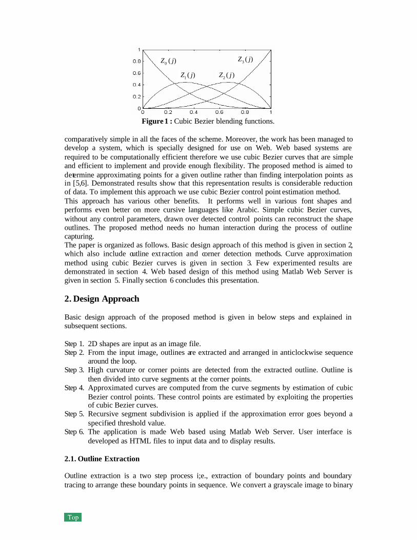
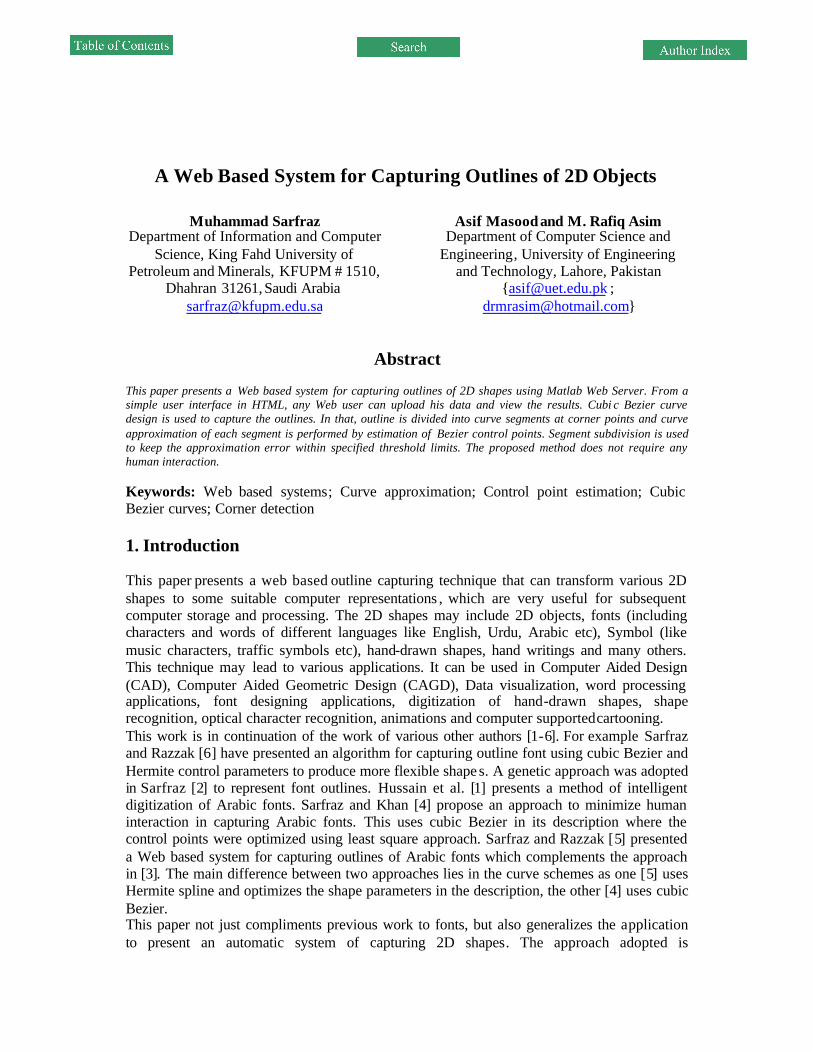
Figure 1 : Cubic Bezier blending functions. comparatively simple in all the faces of the scheme. Moreover, the work has been managed to develop a system, which is specially designed for use on Web. Web based systems are required to be computationally efficient therefore we use cubic Bezier curves that are simple and efficient to implement and provide enough flexibility. The proposed method is aimed to determine approximating points for a given outline rather than finding interpolation points as in [5,6]. Demonstrated results show that this representation results is considerable reduction of data. To implement this approach we use cubic Bezier control point estimation method. This approach has various other benefits. It performs well in various font shapes and performs even better on more cursive languages like Arabic. Simple cubic Bezier curves, without any control parameters, drawn over detected control points can reconstruct the shape outlines. The proposed method needs no human interaction during the process of outline capturing. The paper is organized as follows. Basic design approach of this method is given in section 2, which also include outline ext raction and corner detection methods. Curve approximation method using cubic Bezier curves is given in section 3. Few experimented results are demonstrated in section 4. Web based design of this method using Matlab Web Server is given in section 5. Finally section 6 concludes this presentation. 2. Design Approach Basic design approach of the proposed method is given in below steps and explained in subsequent sections. Step 1. 2D shapes are input as an image file. Step 2. From the input image, outlines are extracted and arranged in anticlockwise sequence
around the loop. Step 3. High curvature or corner points are detected from the extracted outline. Outline is
then divided into curve segments at the corner points. Step 4. Approximated curves are computed from the curve segments by estimation of cubic
Bezier control points. These control points are estimated by exploiting the properties of cubic Bezier curves.
Step 5. Recursive segment subdivision is applied if the approximation error goes beyond a specified threshold value.
Step 6. The application is made Web based using Matlab Web Server. User interface is developed as HTML files to input data and to display results.
2.1. Outline Extraction Outline extraction is a two step process i;e., extraction of boundary points and boundary tracing to arrange these boundary points in sequence. We convert a grayscale image to binary
)(2 jZ
)(0 jZ
)(1 jZ
)(3 jZ
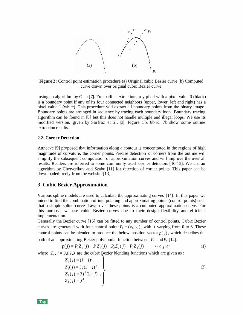
Figure 2: Control point estimation procedure (a) Original cubic Bezier curve (b) Computed
curve drawn over original cubic Bezier curve. using an algorithm by Otsu [7]. For outline extraction, any pixel with a pixel value 0 (black) is a boundary point if any of its four connected neighbors (upper, lower, left and right) has a pixel value 1 (white). This procedure will extract all boundary points from the binary image. Boundary points are arranged in sequence by tracing each boundary loop. Boundary tracing algorithm can be found in [8] but this does not handle multiple and illegal loops. We use its modified version, given by Sarfraz et al. [3]. Figure 5b, 6b & 7b show some outline extraction results. 2.2. Corner Detection Attneave [9] proposed that information along a contour is concentrated in the regions of high magnitude of curvature, the corner points. Precise detection of corners from the outline will simplify the subsequent computation of approximation curves and will improve the over all results. Readers are referred to some commonly used corner detectors [10-12]. We use an algorithm by Chetverikov and Szabo [11] for detection of corner points. This paper can be downloaded freely from the website [13]. 3. Cubic Bezier Approximation Various spline models are used to calculate the approximating curves [14]. In this paper we intend to find the combination of interpolating and approximating points (control points) such that a simple spline curve drawn over these points is a computed approximation curve. For this purpose, we use cubic Bezier curves due to their design flexibility and efficient implementation. Generally the Bezier curve [15] can be fitted to any number of control points. C ubic Bezier curves are generated with four control points ),( iii yxP = , with i varying from 0 to 3. These control points can be blended to produce the below position vector )( jp , which describes the
path of an approximating Bezier polynomial function between 0P and 3P [14]. )()()()()( 33221100 jZPjZPjZPjZPjp +++= 10 ≤≤ j (1)
where iZ , 3,2,1,0=i are the cubic Bezier blending functions which are given as : 3
0 )1()( jjZ −= , 2
1 )1(3)( jjjZ −= , (2) )1(3)( 2
2 jjjZ −= ,
33 )( jjZ = .
(a) (b)
P0
P1 P2
P3
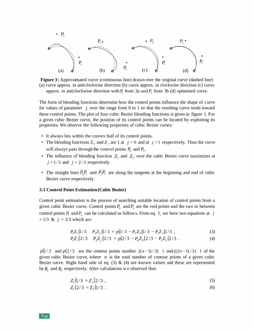
Figure 3: Approximated curve (continuous line) drawn over the original curve (dashed line)
(a) curve approx. in anticlockwise direction (b) curve approx. in clockwise direction (c) curve approx. in anticlockwise direction with 1P from 3a and 1P from 3b (d) optimized curve.
The form of blending functions determine how the control points influence the shape of curve for values of parameter j over the range from 0 to 1 so that the resulting curve tends toward these control points. The plot of four cubic Bezier blending functions is given in figure 1. For a given cubic Bezier curve, the position of its control points can be located by exploiting its properties. We observe the following properties of cubic Bezier curves: • It always lies within the convex hull of its control points. • The blending functions 0Z and 3Z are 1 at 0=j and at 1=j respectively. Thus the curve
will always pass through the control points 0P and 3P . • The influence of blending function 1Z and 2Z over the cubic Bezier curve maximizes at
3/1=j and 3/2=j respectively.
• The straight lines____
10PP and ____
32PP are along the tangents at the beginning and end of cubic Bezier curve respectively.
3.1 Control Point Estimation (Cubic Bezier) Control point estimation is the process of searching suitable location of control points from a given cubic Bezier curve. Control points 0P and 3P are the end points and the two in between control points 1P and 2P can be calculated as follows. From eq. 1, we have two equations at j = 1/3 & j = 2/3 which are:
( ) ( ) ( ) ( ) ( )3/13/13/13/13/1 33002211 ZPZPpZPZP −−=+ , (3) ( ) ( ) ( ) ( ) ( )3/23/23/23/23/2 33002211 ZPZPpZPZP −−=+ . (4)
( )3/1p and ( )3/2p are the contour points number 1)3/)1(( +−n and 1)3/)12(( +−n of the
given cubic Bezier curve, where n is the total number of contour points of a given cubic Bezier curve. Right hand side of eq. (3) & (4) are known values and these are represented by 1R and 2R respectively. After calculations w e observed that:
( ) ( )3/23/1 21 ZZ = , (5) ( ) ( )3/13/2 21 ZZ = . (6)
1P
2P
1P
2P 1P
2P
1P
2P
(a) (b) (c) (d)

Figure 4:. Recursive segment subdivision. Dashed and continues lines are the original and computed curves respectively (a) Before segment subdivision (b) After segment subdivision
By putting the values from eq. (5) & (6) in eq. (4) and substituting 1R and 2R we have:
( ) ( )3/13/1 22111 ZPZPR += , (7) ( ) ( )3/13/1 12212 ZPZPR += . (8)
By multiplying eq. 7 by 2R and eq. 8 by 1R we have:
( ) ( ) ( ) ( )3/13/13/13/1 121211222112 ZPRZPRZPRZPR +=+ . (9)
By simplifying the eq. 9, we have 12 TPP = , (10)
where ( ) ( )( ) ( )3/13/1
3/13/1
2211
2112
ZRZRZRZR
T−−
= , (11)
T is the translation factor between 1P and 2P . As the straight line from control point 0P to 1P is tangent to the cubic Bezier curve and has slope m. Thus control point 1P is to be searched along the tangent line with its slope m. The following procedure can be used to find the control points 1P and 2P
1. Initialize 01 PP =
2. mPP += 11 3. 12 TPP = 4. Draw cubic Bezier curve by calculated control points and determine approximation
error (area between two curves). 5. Repeat step 2 to 4 while approximation error reduces.
Procedure of finding control points 1P and 2P is shown in figure 2. Finally selected control points with minimum approximation error are shown in circles. 3.2 Curve Approximation For a given cubic Bezier curve, curve approximation was computed quite successfully by control point estimation. Approximation error becomes undesirable if the same procedure is used for other curves. It can be seen in figure 3 that the curve approximation is better towards one side (start of curve) and deteriorate towards other side (end of curve). It is because the control point 2P is not along the tangent at 3P which was achieved automatically while
(a) (b)
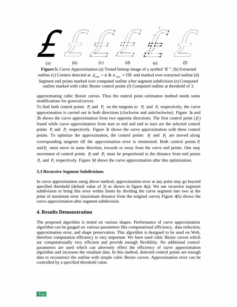
Figure 5: Curve Approximation (a) Tested bitmap image of a symbol “£ ”. (b) Extracted outline (c) Corners detected at 4min =d & 150max =α and marked over extracted outline (d) Segment end points marked over computed outline a fter segment subdivision (e) Computed
outline marked with cubic Bezier control points (f) Computed outline at threshold of 3. approximating cubic Bezier curves. Thus the control point estimation method needs some modifications for general curves. To find both control points 1P and 2P on the tangents to 0P and 3P respectively, the curve approximation is carried out in both directions (clockwise and anticlockwise). Figure 3a and 3b shows the curve approximation from two opposite directions. The first control point ( 1P ) found while curve approximation from start to end and end to start are the selected control points 1P and 2P respectively. Figure 3c shows the curve approximation with these control points. To optimize the approximation, the control points 1P and 2P are moved along corresponding tangents till the approximation error is minimized. Both control points 1P and 2P must move in same direction, towards or away from the curve end points. One step movement of control points 1P and 2P must be proportional to the distance from end points
0P and 3P respectively. Figure 3d shows the curve approximation after this optimization. 3.3 Recursive Segment Subdivisions In curve approximation using above method, approximation error at any point may go beyond specified threshold (default value of 3) as shown in figure 4(a). We use recursive segment subdivision to bring this error within limits by dividing the curve segment into two at the point of maximum error (maximum distance from the original curve). Figure 4(b) shows the curve approximation after segment subdivision. 4. Results Demonstration The proposed algorithm is tested on various shapes. Performance of curve approximation algorithm can be gauged on various parameters like computational efficiency, data reduction, approximation error, and shape preservation. This algorithm is designed to be used on Web, therefore computation efficiency is very important. We have used cubic Bezier curves which are computationally very efficient and provide enough flexibility. No additional control parameters are used which can adversely effect the efficiency of curve approximation algorithm and increases the resultant data. In this method, detected control points are enough data to reconstruct the outline with simple cubic Bezier curves. Approximation error can be controlled by a specified threshold value.
(a) (b) (c) (f) (e) (d)
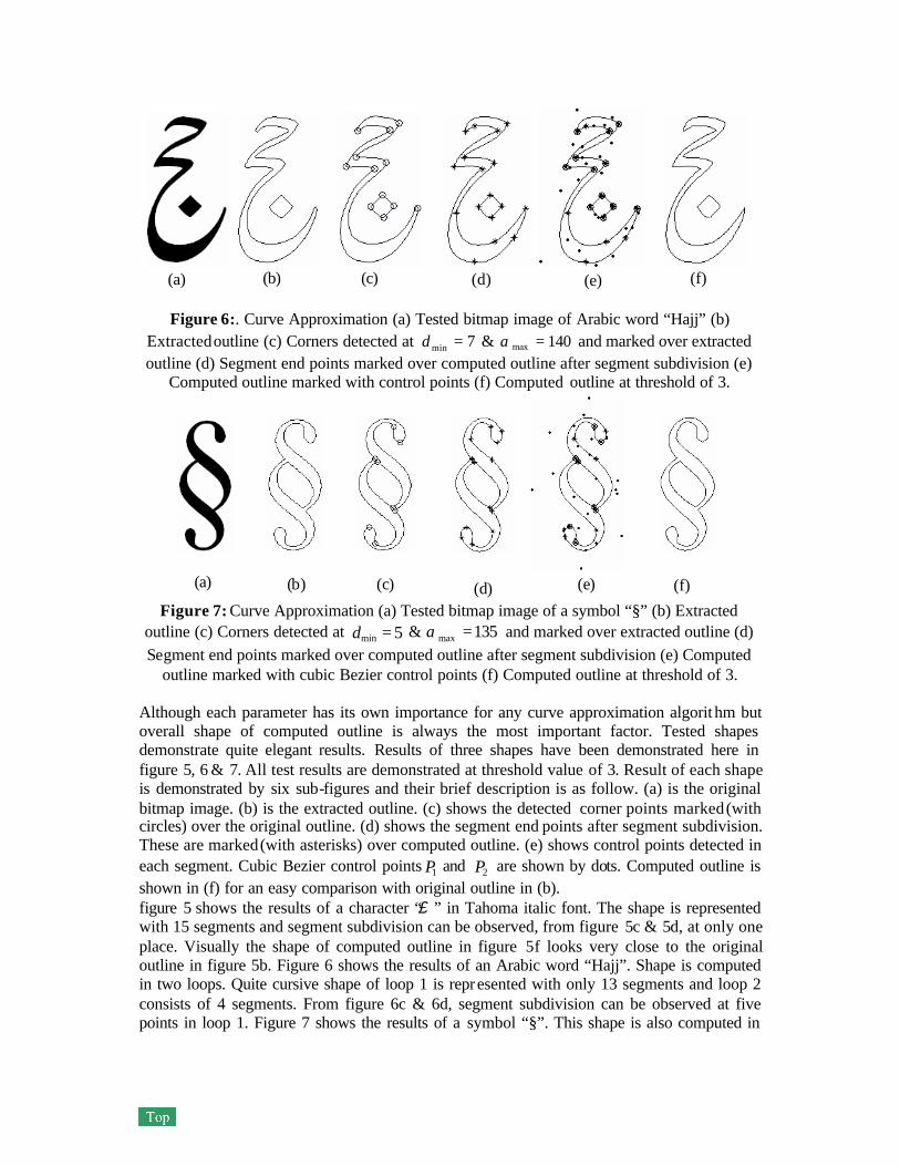
Figure 6:. Curve Approximation (a) Tested bitmap image of Arabic word “Hajj” (b) Extracted outline (c) Corners detected at 7min =d & 140max =α and marked over extracted outline (d) Segment end points marked over computed outline after segment subdivision (e)
Computed outline marked with control points (f) Computed outline at threshold of 3.
Figure 7: Curve Approximation (a) Tested bitmap image of a symbol “§” (b) Extracted outline (c) Corners detected at 5min =d & 135max =α and marked over extracted outline (d) Segment end points marked over computed outline after segment subdivision (e) Computed
outline marked with cubic Bezier control points (f) Computed outline at threshold of 3. Although each parameter has its own importance for any curve approximation algorit hm but overall shape of computed outline is always the most important factor. Tested shapes demonstrate quite elegant results. Results of three shapes have been demonstrated here in figure 5, 6 & 7. All test results are demonstrated at threshold value of 3. Result of each shape is demonstrated by six sub-figures and their brief description is as follow. (a) is the original bitmap image. (b) is the extracted outline. (c) shows the detected corner points marked (with circles) over the original outline. (d) shows the segment end points after segment subdivision. These are marked (with asterisks) over computed outline. (e) shows control points detected in each segment. Cubic Bezier control points 1P and 2P are shown by dots. Computed outline is shown in (f) for an easy comparison with original outline in (b). figure 5 shows the results of a character “£ ” in Tahoma italic font. The shape is represented with 15 segments and segment subdivision can be observed, from figure 5c & 5d, at only one place. Visually the shape of computed outline in figure 5f looks very close to the original outline in figure 5b. Figure 6 shows the results of an Arabic word “Hajj”. Shape is computed in two loops. Quite cursive shape of loop 1 is represented with only 13 segments and loop 2 consists of 4 segments. From figure 6c & 6d, segment subdivision can be observed at five points in loop 1. Figure 7 shows the results of a symbol “§”. This shape is also computed in
(a) (b) (c) (d) (e) (f)
(a) (e) (d) (c) (b) (f)
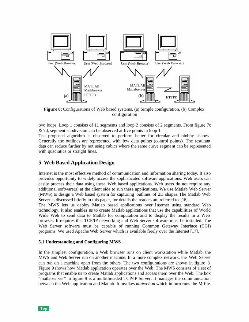
Figure 8: Configurations of Web based systems. (a) Simple configuration. (b) Complex configuration
two loops. Loop 1 consists of 11 segments and loop 2 consists of 2 segments. From figure 7c & 7d, segment subdivision can be observed at five points in loop 1. The proposed algorithm is observed to perform better for circular and blobby shapes. Generally the outlines are represented with few data points (control points). The resultant data can reduce further by not using cubics where the same curve segment can be represented with quadratics or straight lines. 5. Web Based Application Design Internet is the most effective method of communication and information sharing today. It also provides opportunity to widely access the sophisticated software applications. Web users can easily process their data using these Web based applications. Web users do not require any additional software(s) at the client side to run these applications. We use Matlab Web Server (MWS) to design a Web based system for capturing outlines of 2D shapes. The Matlab Web Server is discussed briefly in this paper, for details the readers are referred to [16]. The MWS lets us deploy Matlab based applications over Internet using standard Web technology. It also enables us to create Matlab applications that use the capabilities of World Wide Web to send data to Matlab for computation and to display the results in a Web browser. It requires that TCP/IP networking and Web Server software must be installed. The Web Server software must be capable of running Common Gateway Interface (CGI) programs. We used Apache Web Server which is available freely over the Internet [17]. 5.1 Understanding and Configuring MWS In the simplest configuration, a Web browser runs on client workstation while Matlab, the MWS and Web Server run on another machine. In a more complex network, the Web Server can run on a machine apart from the others. The two configurations are shown in figure 8. Figure 9 shows how Matlab application operates over the Web. The MWS consis ts of a set of programs that enable us to create Matlab applications and access them over the Web. The box “matlabserver” in figure 9 is a multithreaded TCP/IP Server. It manages the communication between the Web application and Matlab. It invokes matweb.m which in turn runs the M file.
User (Web Browser) User (Web Browser) User (Web Browser) User (Web Browser)
MATLAB Matlabserver HTTPD
HTTPD
MATLAB Matlabserver
(a) (b)
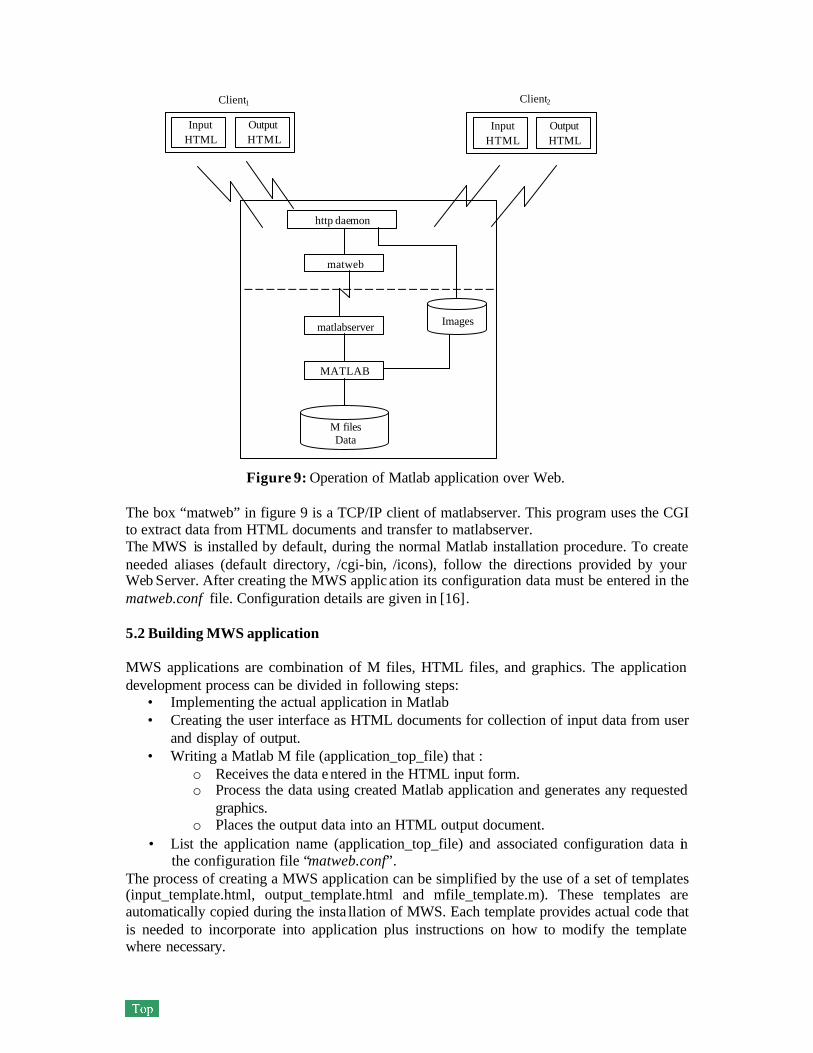
Figure 9: Operation of Matlab application over Web. The box “matweb” in figure 9 is a TCP/IP client of matlabserver. This program uses the CGI to extract data from HTML documents and transfer to matlabserver. The MWS is installed by default, during the normal Matlab installation procedure. To create needed aliases (default directory, /cgi-bin, /icons), follow the directions provided by your Web Server. After creating the MWS applic ation its configuration data must be entered in the matweb.conf file. Configuration details are given in [16]. 5.2 Building MWS application MWS applications are combination of M files, HTML files, and graphics. The application development process can be divided in following steps:
• Implementing the actual application in Matlab • Creating the user interface as HTML documents for collection of input data from user
and display of output. • Writing a Matlab M file (application_top_file) that :
o Receives the data entered in the HTML input form. o Process the data using created Matlab application and generates any requested
graphics. o Places the output data into an HTML output document.
• List the application name (application_top_file) and associated configuration data in the configuration file “matweb.conf”.
The process of creating a MWS application can be simplified by the use of a set of templates (input_template.html, output_template.html and mfile_template.m). These templates are automatically copied during the insta llation of MWS. Each template provides actual code that is needed to incorporate into application plus instructions on how to modify the template where necessary.
Input HTML
Output HTML
Client1
M files Data
Images
MATLAB
matlabserver
matweb
http daemon
Input HTML
Output HTML
Client2
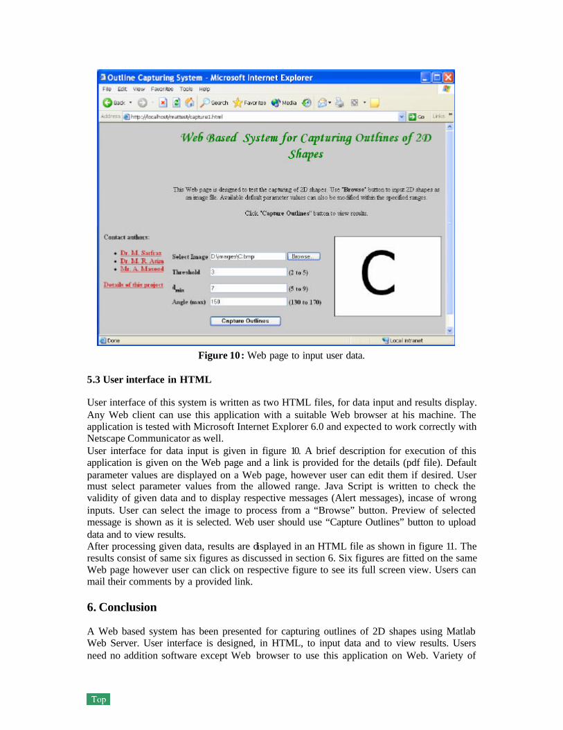
Figure 10: Web page to input user data. 5.3 User interface in HTML User interface of this system is written as two HTML files, for data input and results display. Any Web client can use this application with a suitable Web browser at his machine. The application is tested with Microsoft Internet Explorer 6.0 and expected to work correctly with Netscape Communicator as well. User interface for data input is given in figure 10. A brief description for execution of this application is given on the Web page and a link is provided for the details (pdf file). Default parameter values are displayed on a Web page, however user can edit them if desired. User must select parameter values from the allowed range. Java Script is written to check the validity of given data and to display respective messages (Alert messages), incase of wrong inputs. User can select the image to process from a “Browse” button. Preview of selected message is shown as it is selected. Web user should use “Capture Outlines” button to upload data and to view results. After processing given data, results are displayed in an HTML file as shown in figure 11. The results consist of same six figures as discussed in section 6. Six figures are fitted on the same Web page however user can click on respective figure to see its full screen view. Users can mail their comments by a provided link. 6. Conclusion A Web based system has been presented for capturing outlines of 2D shapes using Matlab Web Server. User interface is designed, in HTML, to input data and to view results. Users need no addition software except Web browser to use this application on Web. Variety of
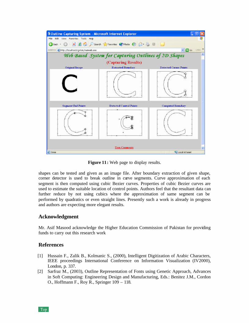
Figure 11: Web page to display results. shapes can be tested and given as an image file. After boundary extraction of given shape, corner detector is used to break outline in curve segments. Curve approximation of each segment is then computed using cubic Bezier curves. Properties of cubic Bezier curves are used to estimate the suitable location of control points. Authors feel that the resultant data can further reduce by not using cubics where the approximation of same segment can be performed by quadratics or even straight lines. Presently such a work is already in progress and authors are expecting more elegant results. Acknowledgment Mr. Asif Masood acknowledge the Higher Education Commission of Pakistan for providing funds to carry out this research work References [1] Hussain F., Zalik B., Kolmanic S., (2000), Intelligent Digitization of Arabic Characters,
IEEE proceedings International Conference on Information Visualization (IV2000), London, p. 337.
[2] Sarfraz M., (2003), Outline Representation of Fonts using Genetic Approach, Advances in Soft Computing: Engineering Design and Manufacturing, Eds.: Benitez J.M., Cordon O., Hoffmann F., Roy R., Springer 109 – 118.
[3] Sarfraz M., Asim M.R., Masood A., (2004) , Capturing Outlines using Cubic Bezier Curves, proc. of 1st IEEE International Conference on Information and Communication Technologies : from Theory to Application. Syria.
[4] Sarfraz, M., and Khan, M., (2000), Towards Automation of Capturing Outlines of Arabic Fonts, The proc. of the Third KFUPM Workshop on Information and Computer Science: Software Development for the New Millennium (WICS’2000), Saudi Arabia, 83-98.
[5] Sarfraz M., Razzak M.F.A., (2003), A Web based system to capture outlines of Arabic fonts, Inf. Sci. 150(3-4): 177-193.
[6] Sarfraz M., Razzak M.F.A., (2002), An Algorithm for Automatic Capturing of Font Outlines, Journal of Computers & Graphics, Elsevier Science, Vol. 26(5), 2002.
[7] Otsu N., (1979), A threshold selection method from gray-level histograms, IEEE Transactions on Systems, Man, and Cybernetics, vol. 9, no. 1, pp. 62-66.
[8] Sonka M., Hlavac V., Boyle R., (2001), Image processing, analysis, and machine vision, Brooks/Cole publication, pp 142-143.
[9] Attneave F., (1954), Some informational aspects of visual perception, Psychological Review, 61:183–193.
[10] Beus H.L., Tiu S.S.H., (1987), An improved corner detection algorithm based on chain coded plane curves, Pattern Recognition, 20:291-296.
[11] Chetverikov D., Szabo Z., (1999), A simple and efficient algorithm for detection of high curvature points in planner curves, Proc. 23rd workshop of Australian Pattern Recognition Group, Steyr, pp.175-184.
[12] Freeman H., Davis L.S., (1977), A corner finding algorithm for chaincoded curves, IEEE Trans. Computers, 26:297-303.
[13] http://visual.ipan.sztaki.hu/publ/oagm99_corn.ps.gz [14] Hearn D., Baker M.P., (1997), Computer Graphics, Prentice Hall publication. [15] Bezier P., (1974), Mathematical and Practical Possibilities of UNISURF in Barnhill,
Riesenfeld R.E., Riesenfeld R.F. , eds. Computer Aided Geometric Design, Academic Press, New York.
[16] Matlab Web Server Manual, (2000), The Mathworks Inc, http://www.mathworks.com/ access/helpdesk/help/pdf_doc/webserver/webserver.pdf.
[17] Apache Server Web Site, http://www.apache.org/