Embed Size (px)
Citation preview
A WATER TUNNEL FLOW VISUALIZATION STUDY
OF THE VORTEX FLOW STRUCTURES
ON THE F/A-18 AIRCRAFT
GRANTOR - NASA AMES RESEARCH CENTER
GRANTEE - CAL POLY STATE UNIVERSITY
GRANT NUMBER NCC 2-620
7/1/89 3/31/91
V_:jL!A!.ITArlr!_N _,TLi_Y __-F TbI _ Vi;_I'_:X kLtJ_4
JCr_?ort, i dul. I -_<>,s - L,t "_<_r. 1 °#}
(r :_I iforni :_ _>ol yL<,chili c St;,J_,.._.o Univ.} 12<* i; ;L, I07
Principal InvestigatorDr. Doral R. Sandlin
Student Investigator
Edgar J. Ramirez
Cal Poly State University
San Luis Obispo, CA 93407
July 1991
https://ntrs.nasa.gov/search.jsp?R=19910017812 2018-07-03T12:03:14+00:00Z
ABSTRACT
A WATER TUNNEL FLOW VISUALIZATION STUDY OF THE
VORTEX FLOW STRUCTURES ON THE F/A-18 AIRCRAFT
Edgar J. Ramirez
November 1990
The vortex flow structures occurring on the F/A-18 aircraft at
high angles of attack have been investigated. A water tunnel was used to
gather extensive flow visualization data on the forebody vortex and the
wing leading-edge extension vortex. The longitudinal location of
breakdown of the leading-edge vortex was found to be consistently
dependent on the angle of attack. Other parameters such as Reynolds
number, model scale, and model fidelity had little influence on the
overall behavior of the flow structures investigated. The lateral location
of the forebody vortex system was greatly influenced by changes in the
angle of sideslip. Strong interactions can occur between the leading-
edge extension vortex and the forebody vortex. Close attention was thus
paid to vortex induced flows on various airframe components of the
F/A-18. Reynolds number and angle of attack greatly affected the
swirling intensity, and therefore the strength of the studied vortices.
Water tunnel results on the F/A-18 correlated well with those obtained
in similar studies at both full- and sub-scale levels. The water tunnel can
provide, under certain conditions, good simulations of realistic flows in
full-scale configurations.
ii

TABLE OF CONTENTS
Chapter Page
List of Symbols ..................................................................................................... v i
List of Tables ......................................................................................................... ix
List of Figures ........................................................................................................ x
1. Introduction ............................................................................................................. 1
Perspective ............................................................................................. 1
The Water Tunnel as a Flow Visualization Tool ..................... 2
Leading Edge and Forebody Vortices ......................................... 4
The NASA High Alpha Technology Program (HATP) ........... 5
The Flow Field Surrounding the F/A-18 ................................. 7
Vortex Flow Studies on the F/A-18 ......................................... 11
Project Justification and Objectives .......................................... 13
2. Experimental Aspects ................................................................................ 16
Flow Visualization Facility ........................................................... 16
Models .................................................................................................. 17
Data Acquisition Methods ............................................................ 18
Test Conditions ................................................................................... 18
Angle of Attack .............................................................. 19
Angle of Sideslip ............................................................. 19
Free Stream Velocity ...................................................... 20
Engine Nacelles Flow Rate ........................................... 20
Test Plan ............................................................................................... 21
iii

o Discussion of Results .............................................................. 23
Examination of Models .................................................. 23
Identification of the Source of Discrepancy in
LEX Vortex Breakdown Data ................................... 25
LEX Vortex Core Breakdown ........................................ 27
Effect of Angle of Attack ..................................... 27
Effect of Angle of Sideslip .................................... 28
Effect of Reynolds Number ................................. 30
Effect of LEX Leading Edge Sharpness and
LEX Surface Smoothness ................................ 31
Effect of Model Scale ........................................... 31
Effect of Model Fidelity ....................................... 31
LEX Vortex Core Location ........................................... 32
Effect of Angle of Attack ..................................... 32
Qualitative analysis .................................... 32
Quantitative analysis ........ . .......................... 33
Effect of Angle of Sideslip .................................... 33
Qualitative analysis .................................... 33
Quantitative analysis ................................... 34
Effect of Reynolds Number .................................. 34
Effect of LEX Leading Edge Sharpness and
LEX Surface Smoothness ................................ 34
Effect of Scale and Model Fidelity ......................... 35
Correlations With Flight Results ............................ 35
Qualitative analysis .................................... 35
iv

o
Quantitative analysis ................................... 35
Forebody Vortex Core Location ..................................... 36
Effect of Angle of Attack ..................................... 36
Effect of Angle of Sideslip ................................... 37
Effect of Reynolds Number ................................. 38
Effect of Forebody Geometry ............................... 38
Effect of Model Scale ........................................... 39
Correlations With Results From Other Studies ......... 39
Location of the Forebody Primary Separation Line .......... 40
Effect of Angle of Attack ..................................... 41
Effect of Reynolds Number .................................. 41
Comparison to a CFD Prediction ........................... 42
Comparison to Flight Results ................................ 42
Interaction Between the LEX and Forebody Vortices ........ 42
Effect of Angle of Attack ..................................... 43
Effect of Angle of Sideslip .................................... 43
Conclusions ........................................................................... 44
References ............................................................................ 47
Appendix A.
Appendix B.
Appendix C.
Computation of Engine Nacelles Flow Rate ......... 52
Vortex Path Reconstruction Method ................... 54
Figures ............................................................ 58

LIST OF SYMBOLS
Ao
Alpha
A/C
b
BART
CFD
CpFMS
F.S., FS
FVF
HARV
HATP
1, L
LEX
NASA
ql
q2
capture area, in2
angle of attack, deg
aircraft
aircraft span, fl
Basic Aerodynamic Research Tunnel
computational fluid dynamics
coefficient of pressure
engine flow rate meter setting
fuselage station, in
Flow Visualization Facility
High Alpha Research Vehicle
High Alpha Technology Program
aircraft or model length, in
leading-edge extension
National Aeronautics and Space
Administration
volume flow rate through one engine
nacelle, gal/min
volume flow rate through both engine
nacelles, gal/min
vf

LIST OF SYMBOLS (continued)
Qmax
R
R1
R 2
R 3
Rec
$1
$2
UHF
VN
go
x, X
No
Xp
maximum volume flow rate through
engine flow meter, gal/min
location of Reattachment Line
primary reattachment line location
secondary reattachment line location
tertiary reattachment line location
Reynolds number based on mean
aerodynamic chord
local span distance from LEX fuselage
junction to LEX leading edge, in
location of primary separation line
location of secondary separation line
ultrahigh frequency
normal component of freestream
velocity, in/sec
free stream velocity, in/sec
longitudinal distance along aircraft or
model measured aft from nose, in
longitudinal world coordinate, in
horizontal picture coordinate, in
vii

LIST OF SYMBOLS (concluded)
Y
Y
No
Yp
zo
O_
8
lateral or spanwise distance measured
outboard from LEX fuselage junction,
in
lateral or vertical distance measured
outboard or vertically from aircraft or
model x axis, in
vertical world coordinate, in
vertical picture coordinate, in
lateral world coordinate, in
angle of attack, deg
angle of sideslip, deg
forebody, cross-sectional
circumferential angle, deg
viii

LIST OF TABLES
Table 1.
Table B. 1.
Table B.2.
Engine Flow Rate Meter Settings as Percentage of
the Maximum Meter Flow
Example of Format Used to Arrange Data for the
V.INIT File
Example of Format Used to Arrange Data for the
VORTEX.IN File
Page
21
55
57
ix

LIST OF FIGURES
Figure
Figure
Figure
Figure
Figure
Figure
Figure
Figure
Figure
Figure
Figure
Figure
o
°
3.
4.
o
o
,
,
o
10.
11.
12.
Page
Vortex Flow Structures on the F/A-18. Angle of
Attack: 30 Degrees; Angle of Sideslip: +6 Degrees 59
The F/A-18 High Alpha Research Vehicle (HARV) 60
The NASA Ames-Dryden Flow Visua!ization Facility 61
Geometry Details of the F/A-18 Aircraft (Figure
From Reference 38) 62
Model of the Cross-Sectional Flow About the LEX
of the F/A- 18 63
Model of the Cross-Sectional Flow About the
Forebody of the F/A- 18 63
Pressure Distributions on the LEX and Forebody of
the F/A-18 HARV (Data and Figures From
Reference 32) 64
Location of LEX Vortex Core Breakdown From
Flight and Ground Facilities 65
Schematic of the NASA Ames-Dryden Water Tunnel 66
F/A- 18 Models Tested 67
Location of Reference Points Used to Attain a Zero-
Degree Angle of Attack 68
Typical Drawing Used to Determine the Angle of
Sideslip 69
X

LIST OF FIGURES (continued)
Figure
Figure
Figure
Figure
Figure
Figure
Figure
Figure
Figure
Figure
13.
14.
15.
16.
17.
18.
19.
20.
21.
22.
Page
Comparison of LEX Local Span Between Water
Tunnel Models 70
Forebody Cross-Sectional Geometry (48A Model and
MD Drawing) 71
Forebody Cross-Sectional Geometry (32A Model and
MD Drawing) 71
Location of LEX Vortex Core Breakdown From the
48A Model and Other Flight and Ground Facilities. 72
Water Tunnel Results of LEX Vortex Core
Breakdown Using 1]48-scale Models of the F/A-18 73
LEX Vortex Core Breakdown on the 48A Model.
Alpha = 15 Degrees; Beta = 0 Degrees 74
LEX Vortex Core Breakdown on the 48A Model
and the 32A Model 75
Longitudinal Variation in the Location of the LEX
Vortex Core Breakdown With Increasing Angle of
Sideslip
LEX Vortex Breakdown Lateral and Longitudinal
Location as a Function of Angle of Attack c_, and
Angle of Sideslip 13 78
Effect of Reynolds Number on the Location of LEX
Vortex Core Breakdown Using the 32A Model 79
76-77
×i

LIST OF HGURES (continued)
Figure
Figure
Figure
Figure
Figure
Figure
Figure
Figure
23.
24.
25.
26.
27.
28.
29.
30.
Page
Comparison of LEX Vortex Core Breakdown
Location Between the Modified and Unmodified
48A Model 79
Effect of Model Scale on the Location of LEX Vortex
Core Breakdown 80
Effect of Model Fidelity on the Location of LEX
Vortex Core Breakdown 80
Variation in the Location of the LEX Vortex Core
With Increasing Angle of Attack
Effect of Angle of Attack (o0 on the Vertical
Location of the LEX Vortex Core. Angle of
Sideslip 13= 0 Degrees 84
Effect of Angle of Attack (o0 on the Lateral Location
of the LEX Vortex Core. Angle of Sideslip 13= 0
Degrees 85
Effect of Angle of Sideslip on the Lateral Location of
the LEX Vortices. Alpha = 25 Degrees; Beta= 5.5
Degrees 86
Effect of Angle of Sideslip (13) on the Vertical
Location of the Leeward LEX Vortex Core.
Angle of Attack oc = 30 Degrees 87
81-83
xii

LIST OF FIGURES (continued)
Figure
Figure
Figure
Figure
Figure
Figure
31.
32.
33.
34.
35.
36.
Effect of Angle of Sideslip (13) on the Lateral
Location of the Leeward LEX Vortex Core.
Angle of Attack o_= 30 Degrees
Comparison of the LEX Vortex Core Location
Between Water Tunnel and Flight Results
Comparison of the LEX Vortex Core Vertical
Location Between Water Tunnel and Flight Data.
Angle of Attack a = 25 Degrees; Angle of Sideslip
13= 0 Degrees
Comparison of the LEX Vortex Core Lateral
Location Between Water Tunnel and Flight Data.
Angle of Attack c_ = 25 Degrees; Angle of Sideslip
13= 0 Degrees
Comparison of the LEX Vortex Core Vertical
Location Between Water Tunnel and Flight Data.
Angle of Attack a = 30 Degrees; Angle of Sideslip
13= 0 Degrees
Comparison of the LEX Vortex Core Lateral
Location Between Water Tunnel and Flight Data.
Angle of Attack ot = 30 Degrees; Angle of Sideslip
13= 0 Degrees
Page
88
89
90
91
92
93
xiii

LIST OF FIGURES (continued)
Figure
Figure
Figure
Figure
Figure
Figure
Figure
Figure
Figure
37.
38.
39.
40.
41.
42.
43.
44.
45.
Page
Location of Forebody Vortices. Alpha = 25 Degrees;
Beta = 0 Degrees 94
Location of Forebody Vortices (Effect of Angle of
Sideslip). Alpha = 25 Degrees; Beta = 4.0 Degrees 95
Location of Forebody Vortices (Effect of Forebody
Geometry). Alpha = 30 Degrees; Beta = 0 Degrees 96
Location of Forebody Vortices (Effect of Model
Scale). Alpha = 25 Degrees; Beta = 0 Degrees 97
Location of Forebody Vortices (Effect of Model
Scale). Alpha = 30 Degrees; Beta = 0 Degrees 98
Comparison of Forebody Vortex Location Between
Water Tunnel and Flight Results [Ref. 23]. Alpha =
30 Degrees; Beta = 0 Degrees 99
Forebody Surface Flow Visualization. Alpha = 20
Degrees; Beta = 0 Degrees 100
Effect of Angle of Attack on the Location of the
Forebody Primary Separation Line 101
Effect of Reynolds Number on the Location of the
Primary Separation Lines of the Forebody 101
x'iv

LIST OF FIGURES (concluded)
Figure 46.
Figure 47.
Figure 48.
Figure 49.
Figure 50.
Figure B.1.
Figure B.2.
Figure B.3.
Page
Comparison of the Location of the Primary
Separation Line Between Water Tunnel Results and
a Laminar Flow CFD Prediction [Ref. 34]. Alpha =
30 Degrees; Beta = 0 Degrees 102
Location of Separation Lines From Water Tunnel
and Flight Results 103
Longitudinal Location of LEX/Forebody Vortex
Interaction and LEX Vortex Breakdown 104
Longitudinal Location of LEX/Forebody Vortex
Interaction From Water Tunnel and Flight Results 104
Comparison Between Flight-measured and Water
Tunnel Results of the Longitudinal Location of the
LEX/Forebody Vortex Interaction as a Function of
the Angle of Sideslip 13(a = 33 Degrees) 105
Location of Cameras and Dimensions Needed for
the Vortex Path Reconstruction Technique 106
Relationships Between Distorted (d) and Undistorted
(u) Picture Coordinates (All Coordinate Values in
Inches) 107
Example of Results Obtained From the Vortex Path
Reconstruction Algorithm 108
×V
CHAPTER1
_oduction
Pgr_pective
Fighter aircraft technology has evolved significantly since World
War II. More demand has been and will continue to be placed on the
aircraft to fly and perform maneuvers under conditions which challenge
not only the physiological capabilities of the pilot, but also the
operational integrity of the aircraft itself. Because of this trend, future
fighter pilots will rely heavily on the ability of their aircraft to quickly
maneuver during an engagement, in order to enjoy the first shot
advantage. In such an environment, aircraft should normally have the
capability for flight at high angles of attack. The flow field about an
aircraft flying in the high angle-of-attack regime is typically dominated
by extensive three-dimensional separated flow. Powerful, concentrated
vortices emanate from various locations of the aircraft, such as the
fuselage forebody, wings, canards, wing leading-edge extensions, etc.
Studies have shown that considerable benefits can be derived from the
presence of the aforementioned vortices in the flow field. For example,
leading-edge extensions can provide increases in maximum lift at high
angles of attack when regular lifting surfaces are stalled. At the same
time, such benefits come with their share of penalties, which are usually
paid in the form of reduced aircraft agility at high angles of attack. It has
been established that this loss of maneuverability (especially lateral-

2
directional) can be attributed to the interaction between the different
vortices occurring at the high angle-of-attack condition [Refs. 1 through
4]. In response to such a drawback, different alternatives have been
explored in an effort to minimize the adverse effects by manipulating
these vortices [Refs. 5 and 6]. Nevertheless, because of the highly
complex nature of such three-dimensional flow structures, a great deal
of basic research on the subject is still needed in order to provide a
better understanding of these fluid dynamics phenomena.
The present study addresses several issues pertaining to high angle-
of-attack aerodynamics through a water tunnel investigation of the
vortex flow structures occurring on the F/A-18 aircraft at high angles of
attack. Particular attention is paid to the behavior of leading-edge
extension (LEX) and forebody vortices. Vortex flow characteristics,
such as vortex location, vortex breakdown, and vortex interactions are
examined, as well as their sensitivity to various parameters such as
angle of attack, angle of sideslip, and Reynolds number. Correlations to
flight test data and to results from wind tunnels and other water tunnels
are also presented.
The Water Tunnel as a Flow Visualization Tool
The study of separated flow using flow visualization techniques has
traditionally been carded out in wind tunnel and full-scale flight tests.
The reason for this trend is the belief that the low Reynolds number
(103 to 104 ) typically found in water tunnels prevents the achievement
of dynamic similarity, a basic requirement for the proper correlation and

3
extrapolation of results to full-scale configurations. Certain types of
flows, however, such as vortex flows occurring at high angles of attack
on thin, sharp-edged slender wings show relatively small sensitivity to
variations in Reynolds number [Ref. 1 ]. Fighter-type aircraft which are
geometrically characterized by the presence of thin, highly-swept
surfaces provide a good example of configurations in which the flow
field at high angles of attack is essentially vortex-dominated. In this
context, vortex-dominated flows refer to those where the size of the
vortices involved is substantially greater than any associated boundary
layer. In some cases of particular interest, the vortices originate from
separation of the lower surface flow at fixed locations along the leading
edges of highly-swept wings, leading-edge extensions, canards, etc. This
phenomenon occurs whether the lower surface boundary layer is
laminar or turbulent. As a result, the overall behavior of leading-edge
vortices is considered to be insensitive to Reynolds number [Ref. 7]. In
slender bodies, such as fuselage forebodies, on the other hand, the
location of separation does vary with Reynolds number. However, the
structure of the vortex at high angles of attack does not change much
with Reynolds number [Ref. 1], because the vortex core is located far
enough from the surface of the body where viscous effects are
significantly reduced.
From the preceding argument, it follows that water tunnels can
provide, under certain conditions, good qualitative simulations of high
angle-of-attack vortex flows encountered on thin, sharp-edged, highly-
swept wings, as well as slender bodies.
4
Some of the vortex flow characteristics that can be assessed in a
water tunnel include vortex core trajectories, vortex core breakdown,
interactions among different vortex systems, and interactions of a vortex
system with other airframe components.
As with any flow visualization method, water tunnels suffer from
some limitations regarding the scope of the investigations that can be
conducted in them. Reference 1 suggests that only flow fields that are
vortex-dominated, such as those at high angles of attack, can provide
good representations of higher Reynolds number flows. By contrast,
vortex flows at low angles of attack (10 degrees or lower) occur at
locations which are closer to body surfaces. In these regions, the flow is
viscosity-dominated, and thus Reynolds number effects can increase and
significantly influence vortex flow characteristics.
A thorough discussion regarding the utility of the water tunnel for
the study of vortex flows can be found in Reference 1. Additionally,
References 8 and 9 describe several flow visualization techniques,
including the water tunnel.
Leading Edge and F0rebody Vortices
A large number of studies have been conducted on the vortex
structures encountered in the flow about slender bodies and highly-
swept delta wings positioned at high angles of attack. Typically, the
flow field in the high angle-of-attack environment involves the presence
of vortex flow which originates upon separation of surface flow [Refs.
10 through 12]. In the case of delta wings, separation takes place along

5
the leading edge; whereas in slender bodies, separation occurs along a
line extending downstream from the nose of the body. The vortices thus
formed in delta wings and slender bodies are generally known as
leading-edge vortices and forebody vortices, respectively. Results from
different studies indicate that the behavior of both leading-edge and
forebody vortices exhibits different levels of sensitivity to the variation
of known parameters such as angle of attack, angle of sideslip, Reynolds
number, geometry of the object, etc. [Refs. 13 through 19 ]. The
knowledge gained from the aforementioned studies has helped explain
the overall effect of vortex flow on the aerodynamic characteristics of
full-aircraft configurations, both generic-type and existing fighter
aircraft.
Different methods have been used to gather information on vortex
flow. On the experimental side, wind tunnels, water tunnels, and full-
scale aircraft have provided representative results. On the computational
side, the rapidly maturing field of computational fluid dynamics (CFD)
has made and will continue to make use of experimental results to
develop and validate computer codes.
The NASA Hi2h Aloha
Technology pl_gram (I-IATP)
Several NASA research centers are currently involved in a
program aimed at investigating the high angle-of-attack flight regime.
The High Alpha Technology Program (HATP) is pursuing this goal
through a close coordination of activities performed by ground-based
and flight facilities. The overall objective of the HATP program is to

6
facilitate the development of technologies required to endow future
fighter aircraft with unprecedented capability for flight at high angles of
attack. Specific objectives of the program are:
1. The development of flight-validated design methods to
accurately predict the aerodynamics and flight mechanics of aircraft
flying at high angles of attack.
2. The development of advanced technologies to significantly
improve the handling qualities of current and future fighter aircraft.
The Northrop/McDonnell Douglas F/A-18 aircraft configuration
was selected as the primary testbed for the HATP program. This
decision was made after careful consideration of key aspects pertaining
to high angle-of-attack technology and the potential usage of several
airplanes for flight validation of results from ground-based research
[Ref. 20]. The F/A-18 provides a prime example of the highly vortical
nature of the flow typically found in advanced fighter aircraft. The two
main vortex systems present in the F/A-18 are the LEX vortex and the
forebody vortex (see Figure 1).
Three specific areas of study are contemplated in the HATP
program. They are high angle-of-attack aerodynamics, advanced control
concepts for high angle-of-attack conditions, and maneuver
management.
In the area of aerodynamics, NASA Ames-Dryden Flight
Research Facility is contributing to the HATP program in various ways
[Ref. 21]. A heavily-instnmaented F/A-18 aircraft known as the High
Alpha Research Vehicle or HARV (see Figure 2) has been used in

7
conjunction with a water tunnel facility (see Figure 3) to gather
extensive flow visualization data of the vortex flow structures on the
F/A-18. Some of the vortex flow aspects investigated on the F/A-18
through the HATP program include: (1) characteristics of the surface
flow on the fuselage forebody and LEX, (2) location of forebody
vortices, (3) location of the LEX vortices and their breakdown, (4)
interaction between LEX and forebody vortices, (5) distribution of the
surface pressure on the forebody and LEX, (6) effect of LEX vortex
breakdown on empennage buffeting, and (7) effect of forebody and
LEX vortices on the stability characteristics of the F/A-18.
The Flow Field Surroundin_ the F/A-18
The F/A-18 is a single place, twin engine, multi-purpose, high
performance aircraft manufactured by McDonnell Douglas Corporation
and Northrop Corporation for the US Navy and the US Marine Corps.
The aircraft has the capability for flight at high angles of attack, making
it a prime candidate for research in this flight regime.
Mounted on each side of the aircraft fuselage are wing leading-
edge extensions (LEX's), which are located between fuselage stations
191 and 401. Some cross-sectional views of the aircraft are shown in
Figure 4. The fuselage forebody is composed of an ogive nose cone with
a circular cross section, which gradually evolves into an oblate, elliptical
fuselage.
At high angles of attack, the flow field about the LEX's features a
system of vortices as shown in Figure 5. The approaching flow (VN)

jl
8
first attaches to the lower surface of the LEX and turns outboard
towards the leading edge. Because of the sharp turn at the leading edge,
the flow is forced to separate (S 1) forming a shear layer or vortex sheet.
A primary vortex is then formed as the vortex sheet rolls up inboard
attracted by a low pressure region. Part of the flow coming over the
primary vortex reattaches to the upper surface of the LEX (R 1) and
begins traveling outboard. The reattached flow is first accelerated and
then decelerated until separation occurs ($2), from which a much
weaker counter-rotating secondary vortex develops. An even weaker
tertiary vortex rotating in the same direction as the primary vortex is
further formed as flow coming from over the secondary vortex
reattaches (R2), migrates inboard, and separates ($3). The location of
the secondary and tertiary vortices can, in turn, influence the location of
the primary vortex. Studies have shown that the location of the
secondary vortex in slender delta wings is highly dependent on
Reynolds number due to the closeness of the vortex to the wing surface
where the flow is viscosity-dominated [Ref. 22]. Throughout this report
the primary LEX vortex will be referred to as the LEX vortex.
As with the case of the LEX, the flow field about the fuselage
forebody of the F/A-18 involves the presence of several vortices. Shown
in Figure 6 is a view of the cross-sectional flow about the forebody at
high angles of attack. In general, the flow field surrounding the
forebody greatly resembles that about an ogive. As the normal
component of the flow reaches the windward stagnation point, it splits
and runs attached to both sides of the forebody. Eventually, this

9
boundary layer flow, facing an adverse pressure gradient, separates from
the forebody ($1) as vortex sheets, which roll up to form two counter-
rotating primary vortices. Flow then reattaches at the leeward meridian
(R). Secondary vortices are then formed on the leeward side of the
forebody by a mechanism similar to that which resulted in the LEX
secondary vortex. A literature review on the subject showed no evidence
as to the existence of a tertiary vortex in the forebody flow field.
In water tunnel flow visualizations of the LEX and forebody
vortices, the LEX vortex exhibits greater strength than the forebody
vortex. This difference in strength can be discerned by the higher level
of swirling in the LEX vortex as compared to that in the forebody
vortex. Pressure measurements obtained from the HARV show a greater
level of suction on the upper surface of the LEX than that on the
leeward side of the forebody for the same flight conditions (see Figure
7). Therefore, it can be inferred that the LEX vortex core has a higher
level of suction than the forebody vortex core. Such a difference in core
suction could account for the higher swirling of the LEX vortex and thus
its greater strength relative to the forebody vortex.
Analogous to the case of the leading edge vortex in delta wings,
the LEX vortex increases in diameter in the downstream direction. The
LEX vortex core, however, remains unchanged in size from its point of
origination at the LEX apex until it undergoes breakdown.
The vortex breakdown phenomenon is generally defined as a
sudden deceleration and stagnation of the axial flow along the vortex
core. Many theories have been proposed in an effort to explain the
10
vortex breakdown phenomenon. However, as of yet, none enjoys
complete acceptance. All theories agree that vortex swirling, core
Reynolds number, and pressure gradient along the core directly affect
breakdown. Reference 22 provides a comprehensive compilation of
different breakdown theories.
Experimental studies on vortex flow have reported that the
longitudinal external pressure gradient is the dominant parameter
affecting vortex flows at high angles of attack [Refs. 1, 3, and 25 ]. This
parameter can be simulated well in a water tunnel, thus suggesting that
certain vortex flow characteristics, such as vortex core breakdown can
also be simulated in a water tunnel.
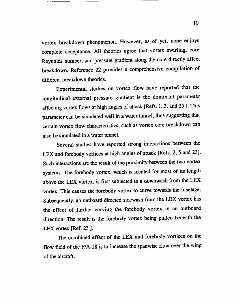
Several studies have reported strong interactions between the
LEX and forebody vortices at high angles of attack [Refs. 2, 5 and 23].
Such interactions are the result of the proximity between the two vortex
systems. The forebody vortex, which is located for most of its length
above the LEX vortex, is first subjected to a downwash from the LEX
vortex. This causes the forebody vortex to curve towards the fuselage.
Subsequently, an outboard directed sidewash from the LEX vortex has
the effect of further curving the forebody vortex in an outboard
direction. The result is the forebody vortex being pulled beneath the
LEX vortex [Ref. 23 ].
The combined effect of the LEX and forebody vortices on the
flow field of the F/A- 18 is to increase the spanwise flow over the wing
of the aircraft.

i
/
11
At high angles of attack, the pressure field about the F/A-18 is
such that strong vortex flows occur over the aircraft, along with
associated increases in lift over what would exist in the absence of
vortex flows.
Vortex Flow Studies on the F/A-18
A significant amount of data on high angle-of-attackl
aerodynamics of the F/A-18 has been gathered from different studies.
Wind tunnel studies have addressed issues such as the degree to
which vortex flows in sub-scale, low speed testing is representative of
the full-scale, in-flight flow field [Ref. 24 ]. Other studies have resulted
in disagreements on the stability characteristics of the F/A-18 [Refs. 2
and 25], even when tested at the same Reynolds number in the same or
different wind tunnels. This apparent scale effect is still not well
understood.
Water tunnel studies have also been conducted on the F/A-18 in
an effort to improve the understanding of the physical aspects of vortex
flows on the aircraft. For example, Reference 2 documents the effects of
different geometrical configurations on forebody and LEX vortex
interactions. The study reports large asymmetries in vortex locations due
to small changes in sideslip, as well as a high sensitivity of vortex
interactions to relatively small variations in geometrical configurations.
Another study has also examined the effects of configuration changes on
the F/A-18's flow field [Ref. 3]. The study concludes that the breakdown
of the LEX vortex produces a highly turbulent region on the aft portion

12
of the F/A-18, accounting for a severe buffeting phenomenon on the
vertical tails of the aircraft, for angles of attack of 25 degrees and
higher. Several other investigations have been directed towards
enhancing the controllability of the F/A-18 at high angles of attack, by
aerodynamically controlling the forebody vortices [Refs. 5, 6 and 26 ].
Reference 26 reports significant improvements in overall forebody
vortex management through the use of blowing, suction, and vortex
generation; with good potential applicability to full-scale aircraft
configurations. The effect of canopy size (single or double seat F/A-18)
on the behavior of LEX and forebody vortices has also been examined
[Ref. 27].
In-flight flow visualization studies have been carded out by
NASA Ames-Dryden using the F/A-18 HARV. Characteristics of both
surface and off-surface flow on the forebody and LEX surfaces have
been investigated. References 28 and 29 report results of surface flow
investigations on the forebody and LEX of the HARV. Primary and
secondary vortex separation lines as well reattachment regions have
been identified using an emitted fluid technique [Ref. 30 ]. Another flow
visualization study on the F/A-18 HARV examined the behavior of LEX
and forebody vortices [Ref. 23]. A smoke generator system allowed the
cores of the vortices to be visualized in flight. The location of LEX
vortex breakdown is shown to be a function of both angle of attack and
angle of sideslip. Flight results are compared to water tunnel results and
show good agreement on LEX vortex breakdown and on the
longitudinal location of interaction between the LEX and the forebody

13
vortices. Pressure measurements on the forebody and LEX of the
HARV have also been obtained [Refs. 31 and 32]. Good correlations of
forebody primary and LEX secondary vortex separation lines with
surface flow visualizations and wind tunnel results are reported.
Numerical predictions of the flow about the F/A-18 using CFD
methods have been performed [Refs. 33 and 34]. Results thus far
obtained agree well with those gathered from in-flight studies on the
HARV and wind tunnel tests using a 6%-scale model of the F/A-18.
project Justification and Objectives
Prior to the time when the present investigation was first
proposed, a number of water tunnel flow visualization studies had been
conducted on the F/A-18. Some of these studies resulted in both
published and unpublished reports on the LEX vortex and forebody
vortex characteristics. One common aspect examined by most of the
aforementioned studies was the longitudinal location of the LEX vortex
core breakdown at different angles of attack. Concurrent with the water
tunnel studies, wind tunnel and flight investigations were assessing the
LEX vortex and forebody vortex behavior. For the most part, data on
LEX vortex characteristics were correlating rather well between the
different facilities involved with F/A-18 high angle-of-attack research.
Only two particular cases had shown difficulties in data correlation. One
involved a discrepancy in lateral stability between different scale
models of the F/A-18 tested in various wind tunnels [Refs. 2 ]. As of
yet, the apparent model scale effect is still not well understood.

14
Reference 2 suggests that the source of discrepancy may be associated
with the location of the primary vortex separation line on the forebody
of the F/A-18; which can greatly influence the interaction of the
forebody vortices with the flow field on the LEX and wing. The other
area of difficulty in data correlation involves conflicting results on the
longitudinal location of LEX vortex breakdown at high angles of attack.
The results in question had been obtained from a water tunnel study
using a 1/48-scale model of the F/A-18 [Ref. 3 ]. The observed location
of LEX vortex breakdown from this study was in conflict with similar
data gathered from a variety of sources, such as wind tunnels, flight
tests, and water tunnels (see Figure 8). The possible cause for these
conflicting results observed in the water tunnel data was believed to be a
model scale effect, a Reynolds number effect, differences between
different water tunnel models, or a combination of these factors.
Consequently, further water tunnel studies were deemed necessary in
order to identify the source of discrepancy in the water tunnel data.
Resolving this issue would help regain some of the confidence that had
been lost on the water tunnel as a valuable tool in helping understand
complex three-dimensional flows. Moreover, the need existed for
expanding the water tunnel data base on forebody vortices. Lastly,
additional correlations of water tunnel results with flight, wind tunnel,
and other water tunnel results were also in great need.
The present study addresses these issues through a flow
visualization study of the F/A-18 aircraft. Flow visualizations were
conducted at the NASA Ames-Dryden water tunnel.

15
The main purpose of the present study is to investigate the high
angle-of-attack vortex flow structures present in the flow surrounding
the F/A-18 aircraft. Specifically, the visualization of LEX and forebody
vortices through water tunnel testing. The objectives of the project are
as follows:
1. Conduct water tunnel tests using scale models of the F/A-18
aircraft. Results from these tests are analyzed to:
a. Verify the existence of a discrepancy in previously
gathered data on LEX vortex breakdown.
b. Determine the cause for conflicting data by examining
the effects of model geometry and model scale effects
on the behavior of LEX vortices.
c. Update the water tunnel data base on F/A-18 LEX
vortex breakdown.
2. Expand the water tunnel data base on F/A-18 forebody
vortices by documenting primary separation lines, surface
flow, vortex core location, and interaction with LEX vortices.
3. Correlate water tunnel test results with flight, wind tunnel, and
other water tunnel test results gathered from previous studies.
CHAPTER 2
Experimental Aspects
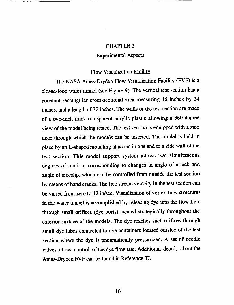
Flow Visualization Facility
The NASA Ames-Dryden Flow Visualization Facility (FVF) is a
closed-loop water tunnel (see Figure 9). The vertical test section has a
constant rectangular cross-sectional area measuring 16 inches by 24
inches, and a length of 72 inches. The walls of the test section are made
of a two-inch thick transparent acrylic plastic allowing a 360-degree
view of the model being tested. The test section is equipped with a side
door through which the models can be inserted. The model is held in
place by an L-shaped mounting attached in one end to a side wall of the
test section. This model support system allows two simultaneous
degrees of motion, corresponding to changes in angle of attack and
angle of sideslip, which can be controlled from outside the test section
by means of hand cranks. The free stream velocity in the test section can
be varied from zero to 12 in/sec. Visualization of vortex flow structures
in the water tunnel is accomplished by releasing dye into the flow field
through small orifices (dye ports) located strategically throughout the
exterior surface of the models. The dye reaches such orifices through
small dye tubes connected to dye containers located outside of the test
section where the dye is pneumatically pressurized. A set of needle
valves allow control of the dye flow rate. Additional details about the
Ames-Dryden FVF can be found in Reference 37.
16

17
Models
Models of the F/A-18 used were constructed from commercially
available hobby shop plastic kits. Scales of the models tested were 1/32
and 1/48. Configuration of the models were landing gear up, no stores,
wing leading-edge flaps deflected 34 degrees down, and trailing-edge
flaps undeflected. This configuration corresponds to flight at angles of
attack of 26 degrees or higher. All models used featured flow-through
inlets to simulate engine inlet suction.
For the present study, the following four models were used (see
Figure 10):
1. An existing 1/48-scale model, which in this report will be
referred to as the "48A model." This model was subjected
to a modification which involved increasing both the LEX
leading-edge sharpness and the LEX upper and lower surface
smoothness.
2. Another 1/48-scale model, from which conflicting
results on LEX vortex breakdown were obtained in an
earlier study [Ref. 3 ]. In this report, this model will be
referred to as the "48B model."
3. A newly-built 1/48-scale model, which is as representative as
possible of the full-scale aircraft. This model is referred to as
the "48C model."
4. An existing 1/32-scale model used in earlier tests, and
which is denoted as the "32A model."

18
All models, except for the 48B model, were marked with lines at
specific fuselage and wing span stations as an aid in identifying the
location of LEX vortex breakdown.
Data Acouisition Methods
All water tunnel tests conducted in the present investigation were
recorded using two video cameras. Two identical still cameras with the
capability for simultaneous triggering were also used. For each test
condition, top views perpendicular to the longitudinal axis of the model
were obtained along with the corresponding side view. An additional 35
mm. camera was used occasionally to document exceptional features of
the flows being visualized.
Because of the highly three-dimensional nature of the flows that
were visualized in the water tunnel, it became apparent that a third
method was necessary to documents those aspects of the flow that can
only be discerned by direct observation. Thus, notes were taken and
sketches were drawn of the flow visualizations as each water tunnel test
was being carded out.
Tes[ Conditions
The Ames-Dryden water tunnel has the capability to vary four
different experimental parameters, even when the facility is operating.
These experimental parameters are angle of attack, angle of sideslip,
free stream velocity, and flow rate through the engine nacelles.

19
An_le of Attack
Angle of attack could be varied by turning a hand crank
connected to the model support system. A seven-inch radius protractor
attached to the inner side of a test section wall was used to read the
angle of attack. Typically, before a test was conducted, the model would
be positioned at zero angle of attack using a plumb line and two
reference points on the model (see Figure 11). This technique assumes
that the test section is accurately oriented vertically. With the model
positioned at zero angle of attack, a reading was taken from the
protractor, which would then be used throughout the test as the zero
angle-of-attack reference. For the present investigation, angle of attack
was varied between zero and 50 degrees for the 1/48-scale models, and
between zero and 45 degrees for the 32A model. This difference was
due to test section size limitations.
An_le of Sideslio
Angle of sideslip could be varied also by turning a hand crank
connected to the model support system. In order to arrive at the correct
setting of sideslip, the following procedure was used. First, the angle of
sideslip was drawn on a top-view sketch of the model (see Figure 12).
The center of rotation in the drawing was located so as to agree with that
on the model support system. A plumb line was then used to place the
model at the no-sideslip condition. Subsequently, the model was
sideslipped until the orientation of the model with respect to the plumb
line agreed with that in the drawing. Angles of sideslip in the 1/48-scale

20
models varied between zero and nine degrees. Because of the bigger
size of the 32A model, angles of sideslip for this model could only be
varied between zero and 6.5 degrees.
Free Stream V_locity
Variation of the free stream velocity provided a means to vary the
Reynolds number. However, it is important to recognize that increases
in free stream velocities can invariably lead to increments in the level of
free stream turbulence in the test section of the water tunnel. For the
ranges of free stream velocities employed in the present study, it was
assumed that the effects of increased free stream turbulence were
minimal. Most of the tests in the present study were conducted at a free
stream velocity of 3 inches/second, which corresponds to a unit
Reynolds number of 2.3 x 10 4 per foot, and which has been found to
produce good flow visualizations. A few selected tests were carded out
with a free stream velocity of 9 inches/second, corresponding to a unit
Reynolds number of 7.0 x 10⁴ per foot.
Eneine Nacelles Flow Ratev
In order to realistically simulate the flow patterns about the
models, water was drawn through the engine inlets of the models to
simulate engine flow. A pair of flexible plastic tubes connected to the
exhaust nozzles carded the simulated engine flow to a flow meter gauge
located outside of the test section. By changing the setting in the gauge,
it was possible to vary the flow through the engine nacelles.The

21
following table shows the different flow meter settings used in the
present study (computations are presented in Appendix A).
Table 1
Engine How Rate Meter Settings as Percentage
of the Maximum Meter Flow
Free Stream
Velocity (in/sec)
3
9
Model Scale
1/48 1/32
22.94 a
68.83 a
51.62 a
54.45 b
asetting using a 1.80 gal/min flow meter
bsetting using a 5.12 gal/min flow meter
Test Plan
Water tunnel testing for the present study was divided into three
phases:
1. Phase I: Testing conducted on the 48A model and on the 48B
model. Objective: Verify the existence of a discrepancy in previously
gathered data on LEX vortex breakdown, and investigate the effect of
LEX surface smoothness and leading-edge sharpness on the behavior of
LEX and forebody vortices.
2. Phase II: Testing conducted on the 32A model. Objective:
Examine the effect of model scale, Reynolds number, angle of attack,
and angle of sideslip on LEX and forebody vortex characteristics,
including location, breakdown, and interaction between the two vortex

1/
22
systems. Additionally, forebody surface flow visualizations are included
in this phase.
3. Phase 1II: Testing conducted on the 48C model. Objective:
Study the effect of model fidelity on LEX and forebody vortex
characteristics.
CHAPTER 3
Discussion of Results
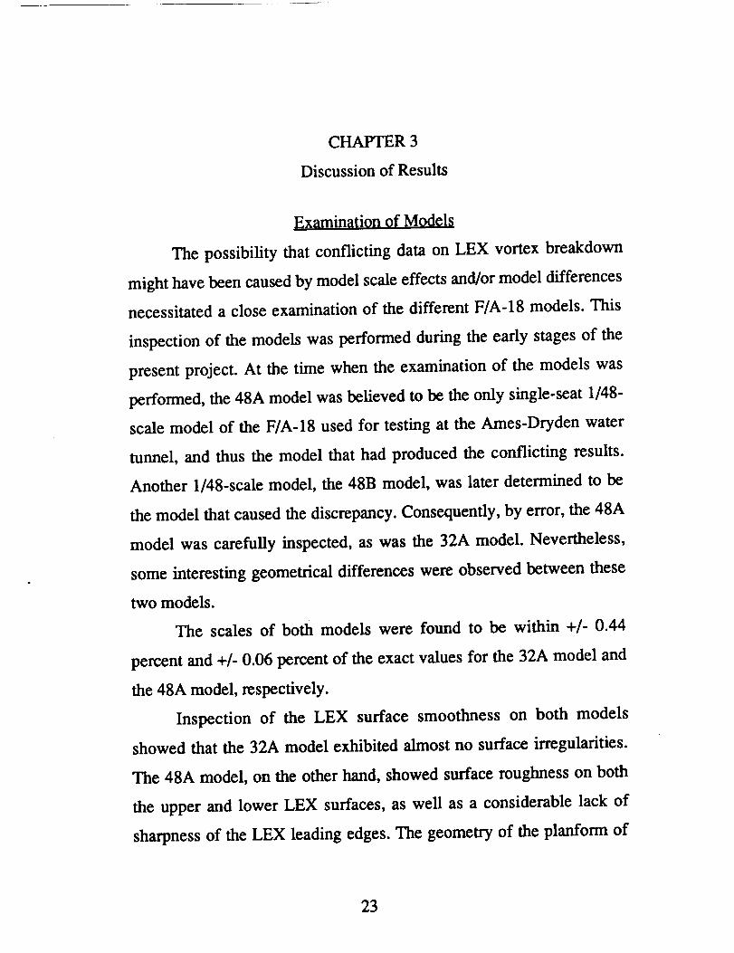
Examination of Models
The possibility that conflicting data on LEX vortex breakdown
might have been caused by model scale effects and/or model differences
necessitated a close examination of the different F/A-18 models. This
inspection of the models was performed during the early stages of the
present project. At the time when the examination of the models was
performed, the 48A model was believed to be the only single-seat 1/48-
scale model of the F/A-18 used for testing at the Ames-Dryden water
tunnel, and thus the model that had produced the conflicting results.
Another 1/48-scale model, the 48B model, was later determined to be
the model that caused the discrepancy. Consequently, by error, the 48A
model was carefully inspected, as was the 32A model. Nevertheless,
some interesting geometrical differences were observed between these
two models.
The scales of both models were found to be within +/- 0.44
percent and +/- 0.06 percent of the exact values for the 32A model and
the 48A model, respectively.
Inspection of the LEX surface smoothness on both models
showed that the 32A model exhibited almost no surface irregularities.
The 48A model, on the other hand, showed surface roughness on both
the upper and lower LEX surfaces, as well as a considerable lack of
sharpness of the LEX leading edges. The geometry of the planform of
23

24
the LEX was also studied between the two models. Figure 13 shows a
comparison of LEX planforms measured from the two models, from a
full-scale F/A-18 aircraft, and from a drawing of the F/A-18 provided by
McDonnell Douglas (MD). As can be seen, the models' LEX shape
agrees well with that of the aircraft and the drawing.
The forebodies of the models were also examined; again showing
that the 32A model exhibited much less surface roughness than the 48A
model. A vernier caliper was used to measure the height and width of
the forebodies of the two models, as well as that on the MD drawing.
Results are presented in Figures 14 and 15. As shown in Figure 14, the
forebody cross section in the 48A model evolves from a horizontal
ellipse into a vertical ellipse, which disagrees with the MD drawing. For
any station on the forebody of the 48A model, the cross section area is
larger than that obtained from the MD drawing. Figure 15 shows results
for the 32A model. As can be seen, the forebody cross section in the
32A model agrees well with that in the drawing by evolving from a
circle into a vertical ellipse. Moreover, for much of the forebody the
elliptical cross-sectional area is larger than that in the MD drawing.
Based on the above observations, the decision was then made to
study the effect of LEX leading-edge sharpness, LEX surface
smoothness, and forebody geometry on some LEX and forebody vortex
characteristics. For this purpose, the 48A model was subjected to
modifications to study LEX geometry effects, and a 1/48-scale model
was built to investigate forebody geometry and overall model fidelity
effects.

jt
25
Identification of the Source of
Discrepancy in LEX Vortex Breakdown Data
As part of the investigation to determine the source of conflicting
data on the LEX vortex breakdown, the 48A model was tested in the
water tunnel at a Reynolds number (Rec) of 5.5 x 10³ based on a mean
aerodynamic chord of 2.88 inches in 1/48 scale. This Reynolds number
corresponds to that of the test involving the conflicting results. Figure
16 presents results on the location of the LEX vortex core breakdown
from the test conducted on the 48A model. As shown, data from the
48A model did not duplicate the discrepant results [Ref. 3], but instead
are closer to the results from various other tests. This situation raised
questions as to whether the 48A model was in fact that which produced
the controversial results. The decision was then made to examine all
published water tunnel results on LEX vortex breakdown from 1/48-
scale models in an effort to establish the identity of the controversial
model. After a thorough review of available photographs from different
water tunnel studies on the F/A-18, it was determined that the
conflicting data belonged to an earlier water tunnel test for which
apparently a different model than the 48A model had been used [Ref. 3].
Having identified the model from which the discrepant results were
obtained (the 48B model), it was deemed logical to conduct a separate
test using the model in question. Figure 17 shows results of the
foregoing investigations. As can be seen, vortex core breakdown results
reported in Reference 3 lay close to those obtained by examining
photographs of top views of the model, which were taken for the same

26
study. On the other hand, breakdown locations identified from side view
photographs nearly match the results from testing the 48A model.
Moreover, results from retesting the 48B model are also close to those
of the 48A model.
Based on the above findings, the following conclusion was
reached as to the possible source of conflicting water tunnel data. The
location of the LEX vortex core breakdown reported in Reference 3
seems to have been interpreted from photographs taken of the top view
of the model. However, these results are in disagreement with results
from side views of the model from the same study. This difference
strongly suggests that parallax was not considered when LEX vortex
core breakdown locations were identified in the study reported in
Reference 3.
In order to properly interpret the longitudinal location of the LEX
vortex core breakdown from a top view of the model, the observer's line
of sight must be kept normal to the plane formed by the longitudinal
axis and the transverse axis of the model; otherwise parallax must be
taken into consideration. Because of this complication, the longitudinal
location of the LEX vortex core breakdown is usually identified from
side views; while the lateral or spanwise location is interpreted from top
views.
27
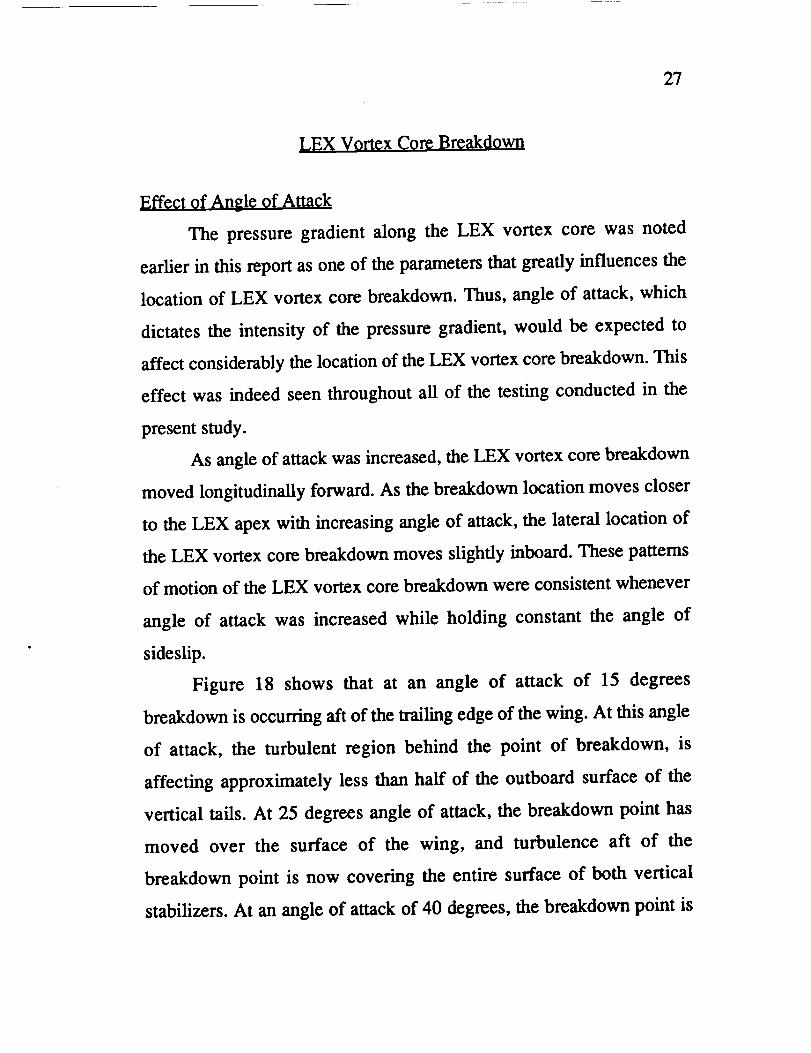
LEX Vort¢x Core Breakdown
Effeqt 9f Angle of Attack
The pressure gradient along the LEX vortex core was noted
earlier in this report as one of the parameters that greatly influences the
location of LEX vortex core breakdown. Thus, angle of attack, which
dictates the intensity of the pressure gradient, would be expected to
affect considerably the location of the LEX vortex core breakdown. This
effect was indeed seen throughout all of the testing conducted in the
present study.
As angle of attack was increased, the LEX vortex core breakdown
moved longitudinally forward. As the breakdown location moves closer
to the LEX apex with increasing angle of attack, the lateral location of
the LEX vortex core breakdown moves slightly inboard. These pattems
of motion of the LEX vortex core breakdown were consistent whenever
angle of attack was increased while holding constant the angle of
sideslip.
Figure 18 shows that at an angle of attack of 15 degrees
breakdown is occurring aft of the trailing edge of the wing. At this angle
of attack, the turbulent region behind the point of breakdown, is
affecting approximately less than half of the outboard surface of the
vertical tails. At 25 degrees angle of attack, the breakdown point has
moved over the surface of the wing, and turbulence aft of the
breakdown point is now covering the entire surface of both vertical
stabilizers. At an angle of attack of 40 degrees, the breakdown point is

28
positioned over the upper surface of the LEX. At an angle of attack of
50 degrees, the point of breakdown is very near the LEX apex. At this
angle of attack, most of the flow field over the aircraft is affected by the
turbulence aft of the breakdown of the LEX vortex cores.
Shown in Figure 19 are results of the LEX vortex core breakdown
from the present study, as compared to flight and wind tunnel results.
Because of the unsteady nature of the LEX vortex core breakdown, the
breakdown locations were obtained from video images by estimating an
average location of the breakdown. The correlations in Figure 19 are
good despite the enormous differences in Reynolds numbers. Moreover,
there seems to be a small parametric trend. As Reynolds number is
increased for constant angle of attack, the location of the LEX vortex
core breakdown appears to move forward. Because of the scatter of the
data points, however, the foregoing trend can only be proposed as
probable. Nevertheless, the overall agreement of results is good,
suggesting that the water tunnel can properly simulate LEX vortex core
breakdown.
Effect of Angl¢ 9f Sideslip
Variation in the angle of sideslip had the following effect on the
longitudinal location of the LEX vortex core breakdown. For constant
angles of attack, increase in the angle of sideslip caused the windward
LEX vortex core breakdown to travel forward, while the leeward LEX
vortex core breakdown moved aft. This trend is graphically depicted in
Figure 20. At an angle of attack of 25 degrees, the asymmetric location

29
of LEX vortex core breakdown with sideslip causes the windward wing
panel to experience a decrease in its spanwise flow, since the swirling in
the turbulent region aft of the point of breakdown is lower than forward
of the point of breakdown. The opposite situation takes place in the
leeward wing panel, where the vortex flow with greater swirling in front
of the point of breakdown affects a larger area of the leeward wing
panel than its counterpart on the windward wing panel. In addition, the
reported vortex breakdown asymmetry would be expected to produce, in
turn, asymmetric lift forces between the LEX's, thus affecting the lateral
stability characteristics of the F/A-18.
Flow around the vertical tails would also be expected to be
affected by asymmetric LEX vortex core breakdown, especially at
moderately high angles of attack (20 degrees to 35 degrees). As angle of
sideslip increases, the longitudinal proximity of the leeward LEX vortex
core breakdown to the leeward vertical tail increases, while the opposite
takes place on the windward side; i.e. LEX vortex core breakdown on
the windward side moves longitudinally away from the windward
vertical tail with increasing angle of sideslip. This differential effect
would be expected to induce differential side forces on the vertical tails,
thus affecting the lateral-directional stability of the F/A-18.
The longitudinal and lateral locations of the LEX vortex core
breakdown have been plotted in Figure 21 for various angles of attack
and sideslip. As reported above, breakdown location on the windward
side moves forward with increased sideslip, while on the leeward side
breakdown location moves aft. Moreover, increases in angle of sideslip

30
causes the windward breakdown point to move inboard, whereas the
opposite happens to the leeward breakdown point, i.e. breakdown moves
outboard. Increases in angle of attack are seen to decrease the
longitudinal and lateral asymmetry of the location of breakdown.
EffeCt of Reynolds N0mber
As explained earlier in this report, Reynolds number was
increased in the water tunnel by increasing the free stream velocity in
the test section. Plotted in Figure 22 are the locations of the LEX vortex
core breakdown for two different Reynolds number. For angles of attack
between 15 and 40 degrees, the higher Reynolds number breakdown
locations are slightly forward of the lower Reynolds number locations of
breakdown. This difference cannot be explained, although it is believed
by the author that increased free stream velocity may be accompanied
by higher free stream turbulence, which could promote early
breakdown. Further experimentation might be necessary to address this
issue. For angles of attack higher than 40 degrees, the trend apparently
is reversed. No definitive statements can be made about such a reversal
in the trend, because the model used for this particular investigation was
the 32A model, which at angles of attack of 45 degrees and higher is
almost in contact with one of the test section walls. Such a proximity to
the wall may cause adverse effects which could influence the quality of
the flow visualizations.

31
Effect of LEX Leading Edge
Sharpness and LEX Surface Smoothness
Increasing the LEX leading-edge sharpness and surface
smoothness produced no appreciable changes in the location of the LEX
vortex core breakdown, as shown in Figure 23. LEX surface smoothness
was expected to produce negligible effects on the LEX vortex core
breakdown, since the LEX vortex core is located far enough from the
LEX upper surface so that changes in the LEX upper surface boundary
layer would be unnoticed by the LEX vortex. Increased sharpness of the
LEX leading edge provided a more fixed flow separation location.
However, Reynolds number effects which become noticeable on
rounded leading-edge, highly-swept surfaces [Ref. 1], did not show in a
clear manner. These observations further emphasize that the adverse
pressure gradient is one of the dominant parameters affecting LEX
vortex core breakdown.
Effect of Model Scale
Shown in Figure 24 is the effect of model scale on the location of
LEX vortex core breakdown. As can be seen, results from two different
scale models agree well, suggesting no influence of model scale in the
location of the LEX vortex core breakdown.
Effect of Model Fidelity
Results on LEX vortex core breakdown from the unmodified 48A
model and the 32A model are compared in Figure 25 to those obtained
32
from the 48C model. Again, no significant differences are observed in
the location of the LEX vortex core breakdown.
LI_X Vortex Core Location
Effect of An_le of Attack
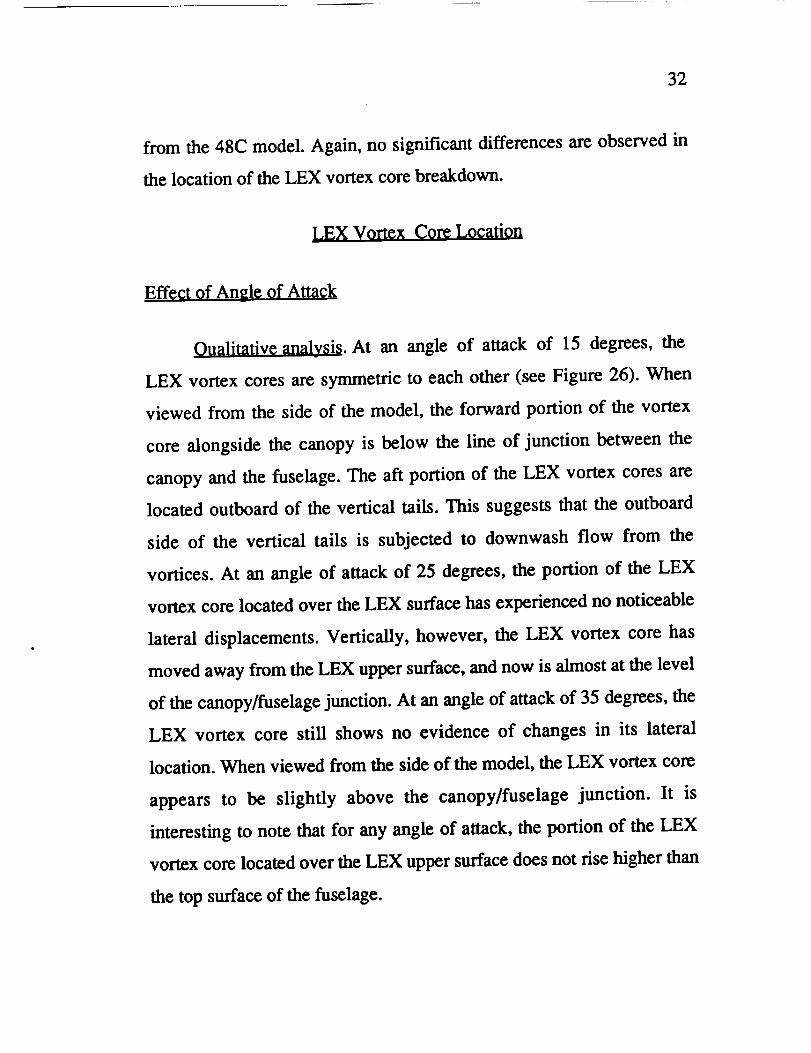
Oualitative analysis. At an angle of attack of 15 degrees, the
LEX vortex cores are symmetric to each other (see Figure 26). When
viewed from the side of the model, the forward portion of the vortex
core alongside the canopy is below the line of junction between the
canopy and the fuselage. The aft portion of the LEX vortex cores are
located outboard of the vertical tails. This suggests that the outboard
side of the vertical tails is subjected to downwash flow from the
vortices. At an angle of attack of 25 degrees, the portion of the LEX
vortex core located over the LEX surface has experienced no noticeable
lateral displacements. Vertically, however, the LEX vortex core has
moved away from the LEX upper surface, and now is almost at the level
of the canopy/fuselage junction. At an angle of attack of 35 degrees, the
LEX vortex core still shows no evidence of changes in its lateral
location. When viewed from the side of the model, the LEX vortex core
appears to be slightly above the canopy/fuselage junction. It is
interesting to note that for any angle of attack, the portion of the LEX
vortex core located over the LEX upper surface does not rise higher than
the top surface of the fuselage.
33
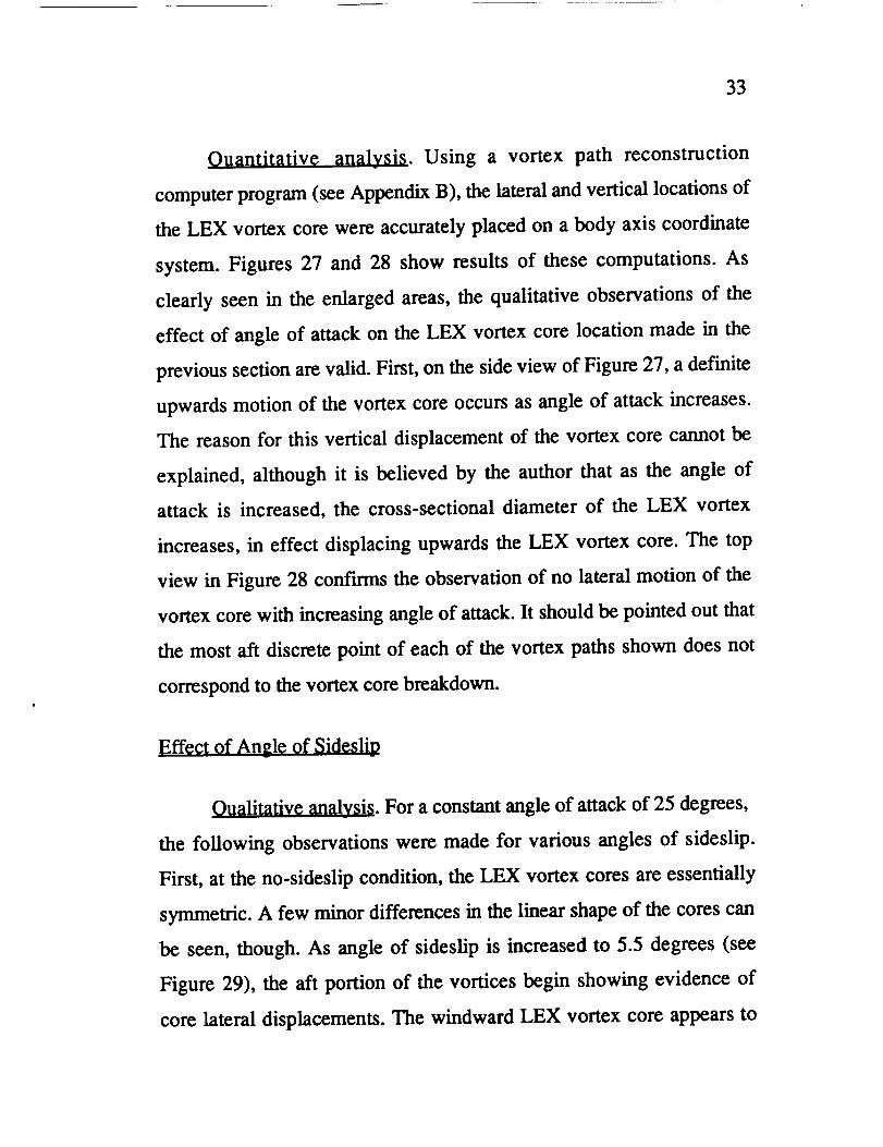
Ouantitative analy_i_. Using a vortex path reconstruction
computer program (see Appendix B), the lateral and vertical locations of
the LEX vortex core were accurately placed on a body axis coordinate
system. Figures 27 and 28 show results of these computations. As
clearly seen in the enlarged areas, the qualitative observations of the
effect of angle of attack on the LEX vortex core location made in the
previous section are valid. First, on the side view of Figure 27, a definite
upwards motion of the vortex core occurs as angle of attack increases.
The reason for this vertical displacement of the vortex core cannot be
explained, although it is believed by the author that as the angle of
attack is increased, the cross-sectional diameter of the LEX vortex
increases, in effect displacing upwards the LEX vortex core. The top
view in Figure 28 confirms the observation of no lateral motion of the
vortex core with increasing angle of attack. It should be pointed out that
the most aft discrete point of each of the vortex paths shown does not
correspond to the vortex core breakdown.
Effect of An_le of Sideslio
Oualitative analysis. For a constant angle of attack of 25 degrees,
the following observations were made for various angles of sideslip.
First, at the no-sideslip condition, the LEX vortex cores are essentially
symmetric. A few minor differences in the linear shape of the cores can
be seen, though. As angle of sideslip is increased to 5.5 degrees (see
Figure 29), the aft portion of the vortices begin showing evidence of
core lateral displacements. The windward LEX vortex core appears to

34
be closer to the center line of the model than the leeward LEX vortex
core. No discernible differences can be visually detected between the
lateral location of the forward portion of the LEX vortex cores; probably
because of the small angle of sideslip.
Ouantitative analysis. Using again the vortex path reconstruction
computer algorithm, locations of the leeward LEX vortex core for three
sideslip conditions and for an angle of attack of 30 degrees were
obtained. Results are presented in Figures 30 and 31. First, the side view
shows hardly any changes in the vertical location of the vortex core with
increasing angle of sideslip. The top view, on the other hand, does show
an outboard motion of the leeward vortex core as sideslip increases.
Effect of Reynolds Number
No appreciable changes could be observed in the location of LEX
vortex core with increased Reynolds number.
Effect of LEX LeadinE-Ed_e
Sharpness and LEX Surface Smoothness
No visible variations could be identified in the location of the
LEX vortex core, after the LEX's of the 48A model were modified. A
line of reasoning similar to that used to explain the insensitivity of the
LEX vortex core breakdown to geometrical modifications of the LEX
could also be used here to explain why the LEX vortex core location is
also insensitive. The behavior of the vortex core is not affected by
disturbances in the boundary layer on the LEX upper surface.
35
Effect of Scale and Model Fidelity
The scale and degrees of fidelity of the models employed in the
present investigation proved to produce no appreciable impact on the
location of the LEX vortex core.
Correlations With Flight Resultsv
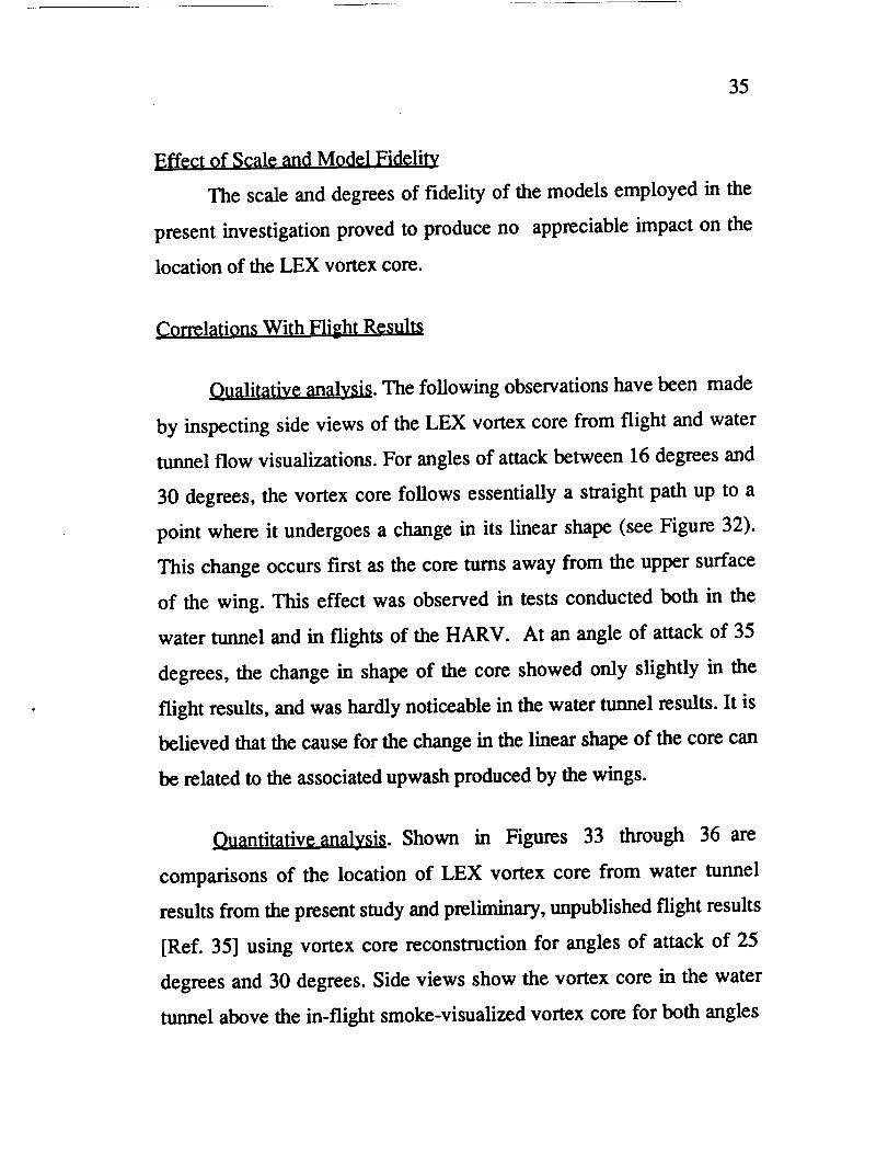
Qualitative analysis. The following observations have been made
by inspecting side views of the LEX vortex core from flight and water
tunnel flow visualizations. For angles of attack between 16 degrees and
30 degrees, the vortex core follows essentially a straight path up to a
point where it undergoes a change in its linear shape (see Figure 32).
This change occurs first as the core turns away from the upper surface
of the wing. This effect was observed in tests conducted both in the
water tunnel and in flights of the HARV. At an angle of attack of 35
degrees, the change in shape of the core showed only slightly in the
flight results, and was hardly noticeable in the water tunnel results. It is
believed that the cause for the change in the linear shape of the core can
be related to the associated upwash produced by the wings.
Ouantitativeanalysis. Shown in Figures 33 through 36 are
comparisons of the location of LEX vortex core from water tunnel
results from the present study and preliminary, unpublished flight results
[Ref. 35] using vortex core reconstruction for angles of attack of 25
degrees and 30 degrees. Side views show the vortex core in the water
tunnel above the in-flight smoke-visualized vortex core for both angles

jt
36
of attack. The only possible explanation for this disagreement is a
difference between the pressure fields on the LEX. Top view
correlations are not as consistent. The 25-degree angle-of-attack case
shows the flight vortex core farther outboard than the water tunnel
vortex core. However, in the 30-degree angle-of-attack case, the results
nearly match. Reference 35 indicates that flight results are accurate to
+/- 8 inches (full scale), which could account for the above difference in
the lateral location of the LEX vortex core between water tunnel and
flight results.
Forebodv Vortex Core Location
Effect of Anele of Attackv
For angles of attack up to 20 degrees, flow on the forebody is
attached. For 25 degrees angle of attack, evidence of separated flow on
the leeward side of the forebody begins to show (see Figure 37). Two
weak primary vortices originate near the nose tip of the forebody, the
cores of which extend downstream near the upper surface of the
fuselage. When viewed from the side of the model, the vortex looks
straight from the nose tip to the highest point of the canopy. Aft of the
canopy, the core curves towards the fuselage to the point where it is
drawn down towards the upper surface of the wing or the LEX. At
moderately high angles of attack (20 to 35 degrees), the core is pulled
laterally outboard over the surface of the wing and beneath the swirling
turbulent region behind the LEX vortex core breakdown. For angles of
attack of 40 degrees and higher, the vortex core is still being drawn

37
laterally, but now flows over the surface of the LEX. In general, as
angle of attack increased, the forebody vortices became stronger as the
level of swirling was observed to increase.
Effect of Anele of Sideslipw
Variations in the angle of sideslip had an effect on the location of
the forebody vortex cores similar to that observed on the LEX vortices.
Increase in angle of sideslip caused the windward forebody vortex core
to move inboard, while the leeward forebody vortex core traveled
outboard (see Figure 38). The displacement of the windward forebody
vortex core was found to be considerably more sensitive to changes in
the angle of sideslip than that of the leeward forebody vortex core. With
no sideslip, and for any high angle of attack, both vortex core remain
symmetrical to each other; laterally located on the outer edge of the
canopy, aft of which they were positioned close to the model's center
line. For angles of sideslip as small as three degrees, the windward
forebody vortex core essentially lined-up with the model's center line,
while the leeward forebody vortex core experienced a much smaller
outboard motion. For angles of sideslip greater than three degrees, the
windward forebody vortex core crosses over the model's center line, and
the leeward forebody vortex core is drawn into the leeward LEX vortex
system. When viewed from the side of the model, the forebody vortex
cores underwent the following changes in their location. With no
sideslip, the cores were essentially lined-up one behind the other. This
condition was kept forward of the canopy for angles of sideslip up to

38
four degrees and angles of attack up to 30 degrees. As sideslip
increased, the windward forebody vortex core moved farther away from
the upper surface of the fuselage. The curvature of the forebody vortex
core aft of the canopy reported previously (effect of angle of attack
section) was reduced. On the other hand, increase in sideslip caused the
leeward forebody vortex core to move closer to the top of the model,
which resulted in it being susceptible to be drawn into the LEX vortex
system.
Effect of Reynolds N_lm_r
Increases in Reynolds number were found to produce no visible
changes in the location of the forebody vortex cores. However, the
forebody vortices exhibited much more strength, which could be
discerned by the increased swirling. Additionally, increase in Reynolds
number caused the unstable and turbulent portions of the forebody
vortex cores to move forward. These changes occurred consistently in
all models and for all angles of attack considered in the present study.
Effect of Forebodv Geometry
Comparison of the forebody vortices between the 48A model and
the 48C model produced the following results. As viewed from the side,
no significant differences were observed in the location of the forebody
vortex cores. When viewed from the top of the model at an angle of
attack of 30 degrees, the forebody vortex cores on the 48A model
showed a curvature directed outboard and located approximately
halfway between the nose tip and the forward most point of the canopy.

je
4
39
Evidence of such a curvature in the forebody vortex cores could not be
seen in the 48C model (see Figure 39). Moreover, the curvature was
found to move forward with increasing angle of attack.
Effect of Model Scale
The lateral location of the forebody vortex cores of the 32A
model and the 48C model seemed nearly identical for the most part.
However, the aft portion of the forebody vortices, near the leading edge
of the vertical tails, showed some differences between the two scale
models at various angles of attack. For example, for an angle of attack
of 25 degrees (see Figure 40), the aft portion of the forebody vortex core
flowed completely over the wing surface on the 32A model; while on
the 48C model the forebody vortex core flowed mostly through the
inboard side of the vertical tails. For angles of attack of 30 degrees and
higher (see Figure 41), the foregoing flow pattern shifted between the
models, so that now the aft portion of the forebody vortex core on the
48C model was drawn farther outboard than in the 32A model. When
observed from the side of the model, hardly any differences could be
noticed on the location of the forebody vortex cores for any angle of
attack.
Correlations With Results From Other S_dies
For angles of attack up to 25 degrees, the forebody vortex core is
located very near the upper surface of the forebody. This observation
was made from both water tunnel and flight test results [Ref. 36]. Aft of
the canopy, however, results from the water tunnel seem to indicate that

40
the forebody vortex core is farther away from the upper surface of the
fuselage than in the flight case. At an angle of attack of 30 degrees,
water tunnel data show that the forebody vortex core still remains very
close to the forebody for most of the forebody, which agrees with the
flight results. Moreover, aft of the canopy the forebody vortex core in
the water tunnel results again seemed farther away from the fuselage
than in the flight results (see Figure 42). Angles of attack of 35 degrees
and higher caused the forebody vortex core to move even further away
from the fuselage in both water tunnel and flight results. In addition, the
curvature of the forebody vortex core aft of the canopy increased with
increasing angle of attack.
Location of the Forelpody prirlaary Separation Line
As part of the effort to expand the water tunnel data base on the
F/A-18, surface flow investigations on the forebody of the F/A-18 were
conducted.
Before results are presented, it is important to point out that
quantitative characteristics of surface flow as documented from a water
tunnel possess limited practical utility due to the presence of strong
viscous effects near the surfaces of the body [Ref. 1]. Nevertheless,
given the current need to improve the understanding of the physics of
vortex flow on the F/A-18, any information that can be gathered on F/A-
18 vortex flows, even if limited in practical applications, would be of
great value.

41
Lack of knowledge of an effective method to visualize surface
flows in water tunnels, coupled with very limited information available
on the subject from existing literature, necessitated conducting surface
flow experiments to develop an effective surface flow visualization
technique. After several trials using different approaches, it was opted
for the method of releasing a stream of dye in front of the object from an
external dye source.
Using this technique, surface flow patterns on the F/A-18
forebody were revealed. However, the only clear piece of information
that could be gathered was the location of the primary separation line.
Figure 43 shows an example of forebody surface flow visualization at
an angle of attack of 20 degrees.
Effect of Ande of Attack
Shown in Figure 44 are the circumferential locations of the
primary separation lines for various angles of attack. As would be
expected, the separation lines move closer to the windward side of the
forebody with increased angle of attack. The noticeable "dip" seen in the
plot is directly attributed to the presence of an antenna cover located on
both sides of the forebody, which causes the boundary layer to separate
closer to the windward side than anywhere else on the forebody.
Effect of Reynolds Number
Increase in Reynolds number caused the primary separation line
to move towards the windward side of the forebody (see Figure 45).
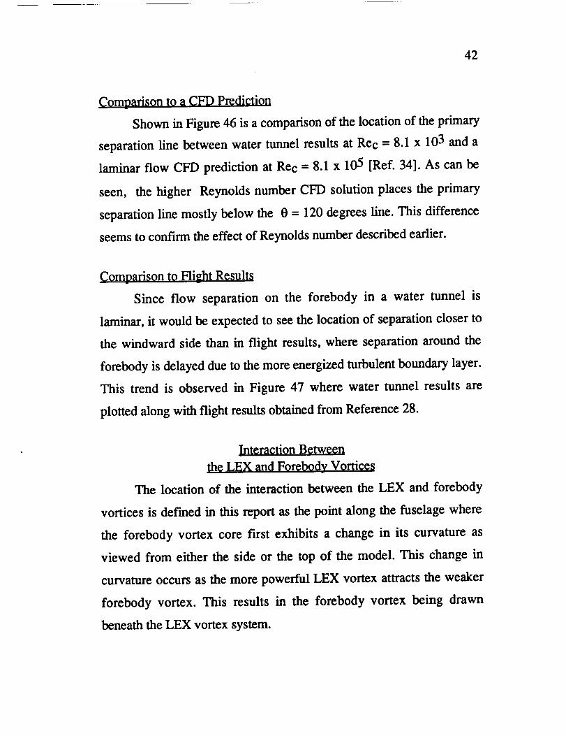
42
Comparisorl to it CFD Prediction
Shown in Figure 46 is a comparison of the location of the primary
separation line between water tunnel results at Rec -- 8.1 x 10³ and a
laminar flow CFD prediction at Rec --- 8.1 x 10⁵ [Ref. 34]. As can be
seen, the higher Reynolds number CFD solution places the primary
separation line mostly below the 0 = 120 degrees line. This difference
seems to confirm the effect of Reynolds number described earlier.
Comoarison to Hight Results
Since flow separation on the forebody in a water tunnel is
laminar, it would be expected to see the location of separation closer to
the windward side than in flight results, where separation around the
forebody is delayed due to the more energized turbulent boundary layer.
This trend is observed in Figure 47 where water tunnel results are
plotted along with flight results obtained from Reference 28.
Interaction Between
the LEX and Forebodv Vorticesv
The location of the interaction between the LEX and forebody
vortices is def'med in this report as the point along the fuselage where
the forebody vortex core first exhibits a change in its curvature as
viewed from either the side or the top of the model. This change in
curvature occurs as the more powerful LEX vortex attracts the weaker
forebody vortex. This results in the forebody vortex being drawn
beneath the LEX vortex system.
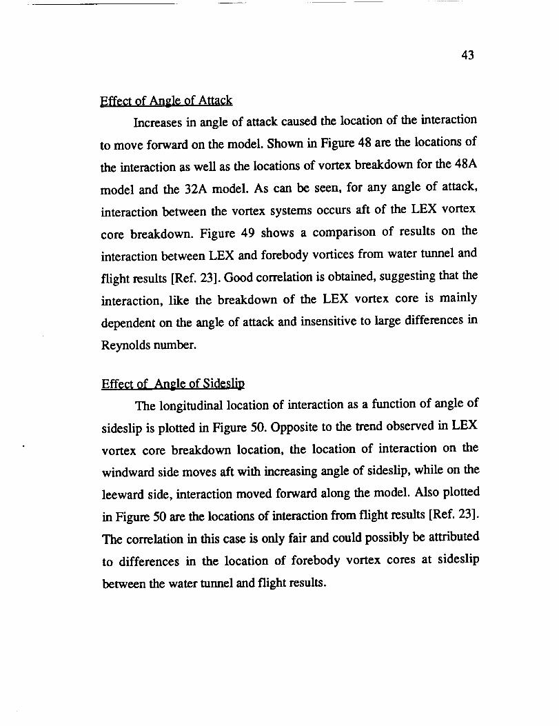
43
]Effect of Angle of Attack
Increases in angle of attack caused the location of the interaction
to move forward on the model. Shown in Figure 48 are the locations of
the interaction as well as the locations of vortex breakdown for the 48A
model and the 32A model. As can be seen, for any angle of attack,
interaction between the vortex systems occurs aft of the LEX vortex
core breakdown. Figure 49 shows a comparison of results on the
interaction between LEX and forebody vortices from water tunnel and
flight results [Ref. 23]. Good correlation is obtained, suggesting that the
interaction, like the breakdown of the LEX vortex core is mainly
dependent on the angle of attack and insensitive to large differences in
Reynolds number.
Effect of Angle of Sideslip
The longitudinal location of interaction as a function of angle of
sideslip is plotted in Figure 50. Opposite to the trend observed in LEX
vortex core breakdown location, the location of interaction on the
windward side moves aft with increasing angle of sideslip, while on the
leeward side, interaction moved forward along the model. Also plotted
in Figure 50 are the locations of interaction from flight results [Ref. 23].
The correlation in this case is only fair and could possibly be attributed
to differences in the location of forebody vortex cores at sideslip
between the water tunnel and flight results.

CHAPTER 4
Conclusions
A flow visualization study has been conducted on the high angle-
of-attack vortex flow structures surrounding the F/A-18 aircraft. The
NASA Ames-Dryden water tunnel was used to investigate the
characteristics of the LEX vortex and forebody vortex systems.
Conflicting results from an earlier water tunnel study involving
the longitudinal location of the LEX vortex core breakdown were
identified. Results from the present study did not duplicate those from
the earlier study. Therefore, an in-depth examination of results from the
earlier study led to the conclusion that a possible source for the
discrepancy was parallax not being taken into consideration in the
interpretation of the location of LEX vortex core breakdown in the
earlier water tunnel study.
The water tunnel database on LEX vortex core breakdown has
been updated. Angle of attack, and thus, pressure gradient was found to
be the main parameter affecting the location of LEX vortex core
breakdown. Other parameters, such as scale of the model tested was
shown to have no significant effect on the location of the LEX vortex
core breakdown. Similarly, LEX leading-edge sharpness and LEX
surface smoothness did not vary the location of the LEX vortex core
breakdown. Assessments of flow visualizations indicate that both
longitudinal and lateral asymmetries in LEX vortex core breakdown
44

45
location have the potential to significantly alter the lateral and
directional stability of the F/A-18. Additionally, for angles of attack of
approximately 25 degrees, the vertical tails of the F/A-18 were
immersed in turbulent flow coming from the breakdown of the LEX
vortex cores.
Angle of attack and angle of sideslip were observed to have
different effects on the vertical and lateral location of the LEX vortex
core. Angle of attack produced no significant lateral but vertical
displacements of the core. Conversely, angle of sideslip caused the core
to displace significantly more laterally than vertically.
Forebody vortex core location was very sensitive to changes in
sideslip. The windward forebody vortex core was observed to move
laterally more than the leeward forebody vortex core with increasing
sideslip. The angle of sideslip also produced changes in the vertical
location of the forebody vortex cores.
The swirling intensity and thus the strength of the LEX and
forebody vortices became greater whenever angle of attack or Reynolds
number was increased.
Primary separation lines on the forebody were observed in the
water tunnel to move closer to the windward side of the forebody with
increasing angle of attack and Reynolds number. These trends agreed
with flight results and CFD predictions, further demonstrating the utility
of the water tunnel as a flow simulation facility.
The location of the interaction between the LEX vortex and the
forebody vortex moved forward as angle of attack was increased. Angle

46
of sideslip produced an effect on the location of the interaction opposite
to that of LEX vortex core breakdown. As sideslip increased, the
windward location of interaction moved aft, while the leeward location
of interaction moved forward.
Extensive correlations were performed between results from the
present study and results from different flight and ground-based
facilities. The best correlations were obtained for those flow
characteristics which were independent of Reynolds number. Thus,
realistic simulations in the water tunnel of full-scale configurations were
successful. This will be the case so long as care is exercised in the
selection of the types of flows to be visualized in the water tunnel.

REFERENCES
1. Erickson, Gary E. Vortex Flow Correlation. AF'WAL:-TR-80-3143,
Wright-Patterson Air Force Base, Ohio, 1980
2. Erickson, Gary E. Water Tunnel F10w Visualization and Wind
Tunnel Data Analysis of the F/A-18. NASA CR- 165859
Northrop Corporation, Aircraft division, Hawthorne, California,
1982.
3. Wentz, William H. Jr. Vortex-f'm In_emetion on a Fighter Aircraft.
AIAA Paper #87-2474-CP, Institute for Aviation Research,
Whichita State University, Wichita, Kansas.
4. McDonnell Aircraft Personnel "F/A-18 Fin Buffet, Project Briefings
on Fin Buffet." Naval Air Developmental Center, May 21, 1986.
5. Malcolm, Gerald N., Skow, Andrew M. ]_nhaneed Controllability
Through Vortex Maninulation on Fighter Aircraft at High An_les
of Attack. Eidetics International, Inc. Visual Aerodynamics
Division, Torrance, California, 1986.
6. Malcolm, G. N., Ng, T.T., Lewis, L.C., and Murri, D.G.,
Develooment of Non-Conventional Control Methods for High
angle of Attack Flight Using Vortex Manioulation. AIAA Paper
89-2192, AIAA 7th applied Aerodynamics Conference, Seattle,
Washington, July 31-August 2, 1989.
Erickson, Gary E., t_xperimental Investigation of Forebodv and
Wing Leading-E_Ige Vortex Intemctions at High Angles of
.
47

48
1
Attack. NASA CR- 165859. NASA Langley Research Center,
Hampton, Virginia, 1982.
Werle, H. Flow Visualization Technioues for the Study of High
Incidence Aerodynamics. AGARD
342. Aerodynamics of Vortical
Dimensions, 25-28 April, 1983.
Conference Proceedings
Type Flows in Three
9. Merzkirch, W., F10w Visualization. Second Edition, Academic
Press, Inc., 1987.
10. Fartshore, I. S., Djilali, N. Flow Separation - Problems and
Possibilities. 9th Australasian Fluid Mechanics Conference,
Auckland, New Zealand, 8-12 December, 1986.
11. Peake, David J., Tobak, Murray. Three-dimensional Separation and
Reattachment. NASA Ames Research Center, Moffett Field,
California.
12. Payne, F.M., Ng, T.T., Nelson, R.C., Schiff, L.B. Visualization
and Flow Surveys of the Leading Edge Vortex Structure on Delta
Wing Planforms. AIAA-86-0330, AIAA 24th Aerospace
Sciences Meeting, January 6-9, 1986.
13. Brandon, Jay M., Nguyen, Luat T. Experimental Study of Effects of
Forebody Geometry on High Angle-of-Attack Stabili _ty. NASA
Langley Research Center, Hampton, Virginia, 1988.
14. Carr, P., Gilbert, W. Effects of Fuselage Forebodv Geometry_ on
Low-Soeed Lateral-Directional Characteristics of a Twin-Tail
Fighter Model at Hi_,h Angles of Attack. NASA TP 1592, 1979.

49
15. Brandon, J.M., Nguyen, L.T. Experimental Study of Effects of
Forebody Geometry_ on High Angle of Attack Static and
Dynamic Stability. AIAA Paper 86-0331, 1986.
16. Wortman, A. Qn Reynolds Number Effects in Vortex Flow Over
_ircraft Wings. AIAA Paper 84-0137,.
17. Keener, Earl R. Flow-Separation Patterns on Symmetric
Forebodies. NASA Technical Memorandum 86016, 1986.
18. Erickson, Gary E. "Water Tunnel Studies of Leading-Edge
Vortices," _I,Aircraft. Vol 19, No. 6, June (1982): 442-448.
19. Wentz, W.H. Effects of Leading-Edge Camber on Low-Speed
Characteristics of Slender delta Win_s. NASA CR-2002,v
October, 1972.
20. NASA. High Alpha Technology Program Official Plan. NASA
Unclassified Internal Document, March 19, 1990.
21. Scott, William B., "NASA Adds to Understanding of High Angle of
Attack Regime". Aviation Week and Space Technology
Magazine, 22 May 1989: 36-42.
22. Payne, Francis M. The Structure of Leading Edge Vortex Flows
Includin_ Vortex Breakdown. University of Notre Dame, Notre
Dame, Indiana, May 1987.
23. DelFrate, John H., Zuniga, Fanny A. In-Flight Flow Field Analysis
on the NASA F-18 High Alpha Research Vehicle With
Comparisons to Ground Facility Data. AIAA Paper 90-0231,
1990.

,/
50
24. Erickson, G.E. et al Experimental Investigation of the F/A-18
Vortex Hows at Subsorlic Through Transonic Soeeds. Invited
AIAA Paper 89-2222, 1989.
25. Banks, D.W., Wind Tunnel Investigation of the Forebody
Aerodynami_ of a Vort¢x -Lift Fighter Configuration at High
Angles of Attack. SAE Paper 881419, October 1988.
26. Ng, T. Terry, Malcolm, Gerald N. Aerodynamic Control of the
F/A-18 Usin_ Forebodv Vortex Control. Eidetics International
Aeronautical Research Division, NASA Contract No. NAS2-
13155, TR90-004, 1990
27. Johnson, Steven A., Fisher, David F. W_t_r T_nn¢l R_sults of a
TF/A-18 and F/A-18 Canopy Flow Visualization Study NASA
Document, June, 1989.
28. Fisher, David F., Richwine, David M., Banks, Daniel W. Surface
Flow Visualization of Separated Flows on the Forebodv of an F-
18 Aircraft anal Wind-Tunnel Mo_lel NASA TM 100436, 1988.
29. Fisher, David F., Del Frate, John H., Richwine, David M. In-Flight
Flow Visualization Characteristics of the NASA F-18 High
Alpha Research Vehicle at High Angles of Attack SAE Paper
892222, 1989.
30. Fisher, David F., Meyer, Robert R., Jr. Flow Visualization
Technioues for Flight Research NASA TM 100455, 1988.
31. Fisher, David F., Banks, Daniel W., Richwine, David M. F-18
High Alpha Research Vehicle Surface Pressures: Initial In-

51
Flieht Results and Correlation with Flow Visualization and
Wind-Tunnel Data NASA TM 101724, 1990.
32. Del Frate, John H., Fisher, David F., Zuniga, Fanny A. In-Flight
F10w Visualization with Pressure Measurements at Low Soeeds
on the NASA F-18 High Alpha Research Vehicle NASA TM
101726, 1990.
33. Ghaffari, F., Luckring, J.M., Thomas, J.L., Bates, B.L. Navi¢r-
Stokes Solutions about the F/A-18 Forebodv LEX Configuration
AIAA Paper 89-0338, 1989.
34. Schiff, Lewis B., Cummings, Russell M., Sorenson, Reese L., Rizk,
Yehia M. Numerical Simulation of High-In_id_n_ Fl0w 9v_r
the F-18 Fuselage Forebodv AIAA Paper 89-0339, 1989.
35. Zuniga, Fanny A. Private Communication with NASA Researcher,
1990.
36. Del Frate, John H. Private Communication with NASA Researcher,
1990.
37. Hall, Capt. Robert M., Del Frate, John H. Interaction Between
Forebodv and Wine Vortices. A Water Tunnel Study AFWAL-
TM-85252, 1986.
38. Linn, Don F-18 Hornet in detail & scale Aero Publishers, Inc.
1982.
39. Bjarke, Lisa. Private Communication with NASA Researcher,
1990.
APPENDIX A
Computation of Engine Nacelles Flow Rate
The flow characteristics of the F/A-18 are well represented in a
water tunnel if the testing facility provides a means to simulate the air
flow through the engine nacelles. The NASA Ames-Dryden Water
Tunnel has such a capability, which was used in the present
investigation to obtain the best possible simulation of flow about the
F/A-18.
The following is a summary of the procedure to determine the
settings for the flow rate meters that were used to control the flow
through the engine nacelles of the different F/A-18 models.
Data needed for the computation:
1. Capture Area (Ao), which is def'med as the cross-sectional
area of the freestream being drawn into the engine inlet. For
the flight regime under study (high angle of attack), the
capture area has an average value of 610.56 in2 (full scale) for
one engine inlet [Ref. 39].
2. Freestream velocity (Vo). For the present study, the freestream
velocities used were 3 in/see and 9 in/sec.
3. Maximum flow through flow meters (Qmax). Two flow
meters are currently operational at the Ames-Dryden water
tunnel. One can indicate up to 1.8 gal/min, while the other
5.12 gal/min.
52

r
f
53
Given the above information, the flow rate (q l) through one
engine nacelle of a 1/48-scale model in a freestream velocity of 3 in/sec
is:
ql = (Ao/482)*Vo
ql -- (610.56 in2/2304)'3 in/sec
ql - 0.795 in3/sec or q1=0.2065 gal/min.
Then the flow rate for both engine nacelles of the 1/48-scale
model of the F/A-18 will be:
q2 = 2*ql
q2 - 2*0.2065 gal/min or q2 ---0.4130 gal/min
the 1.8 ga!/min flow meter, then the setting (FMS) for suchUsing
a meter is:
or
FMS= (q2/Qum)*100%
FMS = [(0.4130 ga./min)/(1.8 gaYmin)]*100%
FMS = 22.94%.
Following a similar procedure, the engine flow rates can then be
computed for the other cases involving the 1/32-scale model and for a
freestream velocity of 9 in/sec.

APPENDIX B
Vortex Path Reconstruction Method
A mathematical formulation making use of photogrammetry has
been developed at NASA Ames-Dryden for the purpose of mapping out
the path followed by the cores of the vortices occurring on the F/A-18 at
high angles of attack. Using this technique, the LEX vortex core
location on a body axis coordinate system has been determined for the
F/A-18 HARV from in-flight flow visualization photographic and video
images. The method uses as input picture coordinates corresponding to
the path of the vortex core from two different views. Additionally, data
regarding the location of the cameras and two different reference points
are supplied to the algorithm as input.
For the present investigation, two still cameras were used for
LEX vortex path reconstruction, which were positioned facing two
adjacent test section walls of the water tunnel. Figure B.1 shows on the
left a "primary view" camera and on the right a "secondary view"
camera. Using a system of rectangular coordinates Xo,Yo,Zo (world
coordinates), each camera is assigned a location in space with respect to
such a coordinate system. The coordinates of two different reference
points are also needed. Such reference points must be chosen so as to
be visible through both cameras. Additionally, the coordinates of points
in the line of sight of each camera must also be known.
54

55
From photographs of each view, the measured horizontal distance
in each photograph between the two reference points is obtained.
The data is arranged in the following format and saved as a file
named: V.INIT.
Table B.1
Example of Format Used to Arrange Data for the V.INIT File
where:
1.
2.
3.
1 13.5944 37.4055 -2.93752 19.4526 28.0175 -10.70233 2.1754 11.2031 36.0000 -28.89585 11.2031 36.0000 -20.09386 -5.0780 40.0469 -9.984407 28.0000 40.0469 -9.98440
8 2.4438
Line 1 contains the world coordinates of reference point 1.
Line 2 contains the world coordinates of reference point 2.
Line 3 contains the horizontal distance between the two
reference points measured from a primary view image.
4. Line 4 contains the world coordinates of the primary view
camera.
5. Line 5 contains the world coordinates of the point in the line of
sight of the primary view camera.
6. Line 6 contains the world coordinates of the secondary view
camera.
7. Line 7 contains the world coordinates of the point in the
line of sight of the secondary view camera.

56
8. Line 8 contains the horizontal distance between the two
reference points measured from a secondary view image.
As the initial data is being gathered and saved in the V.INIT file,
the picture coordinates of the vortex core can also be obtained from
images of both the primary and the secondary view. For the primary
view, an Xp and a yp coordinate of discrete points of the vortex core are
obtained, while for the secondary view only the xp coordinate of the
corresponding points is needed.
Because of the distortion effect described above, it became
necessary to correct the values of the picture coordinates read from the
"distorted" views of the vortex cores. This correction was done by
using relationships between distorted and undistorted picture
coordinates. Such relationships were obtained from knowing in advance
the location of certain specific points on the F/A-18 such as the LEX
apex, the UHF antenna on the top of the fuselage, the intersection of the
left vertical tail leading edge with the fuselage, etc. Thus, by working
"backwards", the undistorted picture coordinates of such points were
obtained and plotted against the distorted values. Figure B.2. shows
such plots and the linear relationships obtained. These formulas were
then used to correct all the distorted picture coordinates of the vortex
cores.
Having corrected the picture coordinates for distortion, the
resulting values are then arranged in the following format and saved in a
file called VORTEX.IN.

57
Table B.2.
Example of Format Used to Arrange Data for the VORTEX .IN File
.6673 2.3375 -.8694
.6228 2.1909 -.9388
.5949 2.0763 -.9735
.5382 1.9297 -.9977
.4833 1.7831 -.9977
.4493 1.6479 -1.0026.3909 1.5022 -.9994.2924 1.3441 -.9638
999.
where:
1. The first column represents the corrected xp coordinate from
the primary view.
2. The second column represents the corrected yp coordinate from
the primary view.
3. The third column represents the corrected Xp coordinate from
the secondary view.
Subsequently, the vortex path reconstruction program (VORTEX)
is run. The results are dumped into a file called VXYZ, which contains
the world coordinates (Xo,Yo,Zo) of the vortex cores.
These coordinates are further transformed to
coordinate system and plotted as shown in
a body axis
Figure B.3.

APPENDIX C
Figures
This appendix contains all the figures. Included are half-tone
pictures made from original color photographs, showing F/A-18 water
tunnel flow visualizations, as well as various other aspects relevant to
the present investigation.
58

59
Forebody VortexCores
Figure 1. Vortex Flow Structures on the F/A-18. Angle of Attack:
30 degrees; Angle of Sideslip: +6 degrees
OR_rNAL PAGE ISOF"P.30,m _,.'_JALrTY
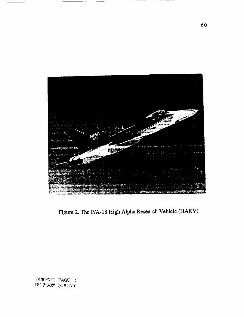
60
Figure 2. The F/A-18 High Alpha Research Vehicle (HARV)

61
Figure 3. The NASA Ames-Dryden Flow Visualization Facility
ORIGINAL PAG£ _3OF PCC;" c),,_ rT'y

62
Figure 4. Geometry Details of the F/A-18 Aircraft (Figure
From Reference 38)

r
/
63
!
m
i_-,lllll
YN
Figure 5. Model of the Cross-Sectional Flow About the LEX of
the F/A-18
Primary vortex
ondary
I vortex core
Figure 6. Model of the Cross-Sectional Flow About the Forebody
of the F/A- 18

64
+ I
Cp "5 i "-_
1,0 .............. Jo . 1,o ,. .o _ _oe, deg, F.S. 70
-.5
_,._._ ..... __.,.,_i
e,_,F.LU
Cp -_:
II M I_ +II0 140 _00 310
e, a_, F.L s,m,
-.5
". _ 13 "oc(1o6)
0.37 10.0 0.1 15.0
---0-.- 0.32 15.2 0.1 12.7
0.30 19.7 -0.1 11.5
Solid symbols - lower sur/lce
41
Cp .1
0
I
4
41
C p -1
0
+I
-3
.:I
Cp -1
0
I.!
t,,s,:W
I ,.
i_.-- _ ,
F,I_ m
=',,>2_ _____"=
F.S. 17
I.
q Ip_ _
]ml
b)LEX
¢pFm....... _;
0 IO f_O rio J40 lOO ' ' MO
e, _ F.S. le4
a) Forebody = kLM&.k F.I-m(WI.0_I} ' : : "ramm +
"*'o'_,.u._4 If / / / \ \ r-t'--4 \P"L 14_.._/' __O"IsRl'J I / / / _ t l
_JL 114 OVJ, 0.1110),, J I/ \\"_.m++_,.m.,,_//
F,S. _rt l_j. o._4l ../
Figure 7. Pressure Distributions on the LEX and Forebody of the
F/A-18 HARV (Data and Figures From Reference 32)

65
Angle of Attack,
degrees
5O
4O
3O
2O
t _te
e*
5t
4
• Water Tunnel - Ref. 3
4 Water Tunnel - Ref. 23
BART Wind Tunnel - Ref. 23
• Flight Smoke - Ref. 23
I I I I I I0.0 0.2 0.4 0.6 0.8 1.0
X/L
4,
. |
0.810 ! - ! • | • ! - ! - i
0.3 0.4 0.5 0.6 0.7 0.9 1.0
X_
Figure 8. Location of LEX Vortex Core Breakdown From Flight
and Ground Facilities
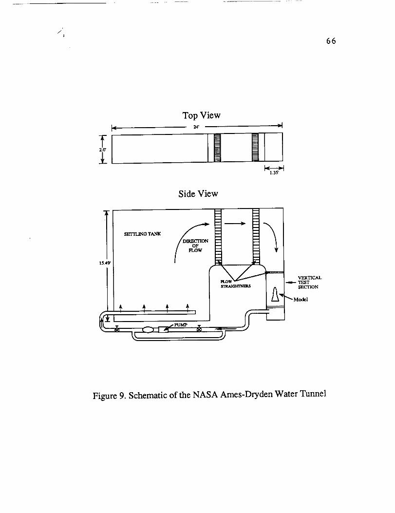
/
66
Top Viewr|
F_
Side View
SETTLING TANK
VERTICALTF__T_.CrlON
Figure 9. Schematic of the NASA Ames-Dryden Water Tunnel

67
48A Model
48B Model
48C Model
32A Model
Figure 10. F/A-18 Models Tested
ORIGINAL PAGE ISOF POOR Q(JAL_

68
Cover of ExteriorAntenna Used asReference Point I
Reference Point 2
Figure 11. Location of Reference Points Used to Attain a Zero-
Degree Angle of Attack

69
= 5 deg_= lOdeg [3 = 15deg
Equivalent Location ofCenter of Rotation ofModel Support System
Figure 12. Typical Drawing Used to Determine the Angle of
Sideslip

7O
35
3O
25
Y,
2Oinches
15
10
• 48A Model
• 32A Model• Full Scale A/C
• Drawing
0
200 22O 240 260 280 300 320
Fuselage Station, in
340 360 380
Figure 13. Comparison of LEX Local SpanBetween Water Tunnel Models

71
Height or
Width, in
50-
4O
3O
I
_'/ o Height Dining0 W_dth l_'awing
10 • = I " 1 • ! • ! " a • i • | " i " !
80 9"0 100 110 120 130 140 150 160 170 180
Funlage Statlon (In)
!
190
Figure 14. Forebody Cross-Sectional Geometry(48A Model and MD Drawing)
Height m"Width, In
SO =
40 _
30,
20 _
m
/ • _ht t_,m,m0 W_lth Drawing
10 - w .... ! - | - - | - J -
80 90 100 1_0 120 130 140 1S0 160 170 180
Fuselage Station (in)
- m
19o
Figure 15. Forebody Cross-Sectional Geometry(32A Model and MD Drawing)

72
Angle ofAttack, deg
o
40-
30
20
_ Water Tunnel 48A Model
B-_ e .__._e BART._..WindTunnel - Ref. 23
;.\-.
"".'__.
10 • I " • I ....0.2 0.3 oi, o.s ols o17 o18 olgXIL
Figure 16. Location of LEX Vortex Core Breakdown Fromthe 48A Model and Other Flight and Ground Facilities

73
6O
,50
4O
30
20'
o
o
• 48B Model - Ref. 3
• 48A Model
'_ 48B Model - I_f. 3 - R_plot top view
[] 48B Model - Ref. 3 - Replot side view
Retest 48B Model
10 • I • i - I • i • I - i • i
0.2 0.3 0.4 0,5 0.6 0.7 0.8 0.9
x_
• '"I
1.0
Figure 17. Water Tunnel Results of LEX Vortex Core BreakdownUsing 1/48-scale Models of the F/A-18

ORIGIN,a.L p,aGE
BLACK AND WHITE FHOTOGRAPH
74
Figure 18. LEX Vortex Core Breakdown on the 48A Model.
Alpha = 15 Degrees; Beta = 0 Degrees

75
60-
Alpha,
degrees
5O
4O
3O
2O
m
I_ra
0
• N
B Water Tunnel 48A Model
• Water Tunnel 32A Model
• BART Wind Tunnel - Ref. 23
• Flight Smoke - Ref. 23
• o He
10 I " i " 1 " I " I " I " l
0.2 0.3 0.4 0.5 0.6 0.7 0.8 0.g
X/L
Figure 19. LEX Vortex Core Breakdown,on the 48A Model and the 32A Model

ORIGINAL PAGE
BLACK AND WHITE PHOTOGRAPH
76
a) Alpha = 25 Degrees; Beta = 3.5 Degrees
b) Alpha = 25 Degrees; Beta = 4.5 Degrees
Figure 20. Longitudinal Variation in the Location of the LEXVortex Core Breakdown With Increasing Angle of Sideslip

p
/
77
0,.,I _ l_Ja,12P.".GE
c) Alpha = 25 Degrees; Beta = 5.5 Degrees
Figure 20. Concluded

78
Y
0.2-
0.3 ¸
0.4
0.50.4
o_= 20 deg
,",= 25 dog
...... _- ..... a. = 30 deg
Note: All _ values shown are m degrees
p,=5.5
_I= P= 5.5
i i i i
0.5 0.6 0.7 0.8
x_
Y
b/2
-1.o
-o.8
.0.6
.o.4
-o.2
o
0.2
0A
O.6
O.8
1.0
/e-.'--"
D
i
3
\\
0 0.2 0.4 0.6 0.8 1.0
X/L
Figure 21. LEX Vortex Breakdown Lateral and Longitudinal Location asa Function of Angle of Attack or,and Angle of Sideslip 13

79
6O
Re ., 2.31F_.,4 per_. (Preeetremnveloc.,,3tn/sec)50 ...... . . (P'r,eestrean_ veloc. - 9 _/see)
10 - , - , - , - . - . . . - ,02 os o., 05 o6 07 oo ooz/L
Figure 22. Effect of Reynolds Number on the Location of LEXVortex Core Breakdown Using the 32A Model
40
3O
2O
6O
50
4O
3O
a
m
ND
I • Unn_ed 48A Model [• ModtOed 48,8, Model
80
10 ' - a - '! - e " • " • I
0.2 0.3 0.4 0.5 0.6 1.0
z/l,
mo
- m -o_7 o., oT.
Figure 23. Comparison of LEX Vortex Core Breakdown Location Between
the Modified and Unmodified 48A Model

/
6O
50
4O
3O
20'
100.2
In
in
B
Arl
D 48A Model
• 32A Model
i
- l - l - i - i - i
0.3 0.4 0.5 0.6 0.7
X_
D&
il
- I
0.8
Figure 24. Effect of Model Scale on the Location of LEX
Vortex Core Breakdown
8O
60-
40'
30 ¸
20
100.2
A
d 48A Model
_._ 4" 3ZA ModeJ
d _ 48C ModeJ
I " | " l " | " | " I " •
0.3 0,4 0,5 0.6 0.7 0.8 0.9
X/Z,
' Figure 25. Effect of Model Fidelity on the Location of LEX
Vortex Core Breakdown

ORIGINAL PAGE
BLACK AND WHITE P!.IOTOGR/_,PN81
........._.!_"-_!i_::','.;._' -_,_.,
a) Alpha = 15 Degrees; Beta = 0 Degrees
b) Alpha = 15 Degrees; Beta = 0 Degrees
Figure 26. Variation in the Location of the LEX Vortex CoreWith Increasing Angle of Attack
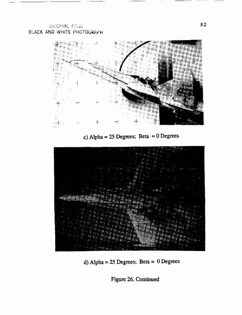
I_'r_iC)rJAL r;,",_ i.:.
BLACK AND WHITE PHOTOGEAFH
82
• .,i... ""1
c) Alpha = 25 Degrees; Beta = 0 Degrees
d) Alpha = 25 Degrees; Beta = 0 Degrees
Figure 26. Continued
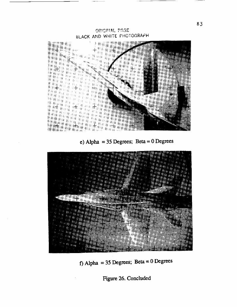
BLACK
OR!QIrJ,aL _" "_"
AND WHITE PHOTOGRAPH
83
e) Alpha = 35 Degrees; Beta = 0 Degrees
f) Alpha = 35 Degrees; Beta = 0 Degrees
Figure 26. Concluded

8d
150
125
Z
100
z
2OO
150
I00
5O
Q _ = 25 deg Area enlmx_ed xbove / I
o a=30d_g I I / /
_ ' .i I I i I i l
100 200 300 400 500 600 700
x
Figure27.EffectofAngle ofAttack(or)on theVerticalLocation
oftheLEX VortexCore.Angle ofSideslip13= 0 Degrees

85
20O _0 240 260 280 3_ 3_ 340
X
360
Y
250
200
150
1oo
50
o
-5o
-I00
-150
-200
a=25 deg
a = 30deg
a=40 deg
0 I00 200 300 400
X
5oo 6OO 700 800
Figure 28. Effect of Angle of Attack (a) on the Lateral Location
of the LEX Vortex Core. Angle of Sideslip [3 = 0 Degrees

86
Figure 29. Effect of Angle of Sideslip on the Lateral Location of
the LEX Vortices. Alpha = 25 Degrees; Beta = 5.5 Degrees

87
150
I00
75
I I ! I I l i I
2QO 22O 240 260 280 3O0 3_0 34O
X
360
Z
2O0
150'
tO0
5O
o
A
= 0.0 deg
_ = 3.5 deg
I I I I I I I
I00 200 300 400 500 600 700
X
Figure 30. EffectofAnglc of Sideslip(13)on the VerticalLocation
of theLeeward LEX Vortex Core. Angle of Attack a = 30 Degrees
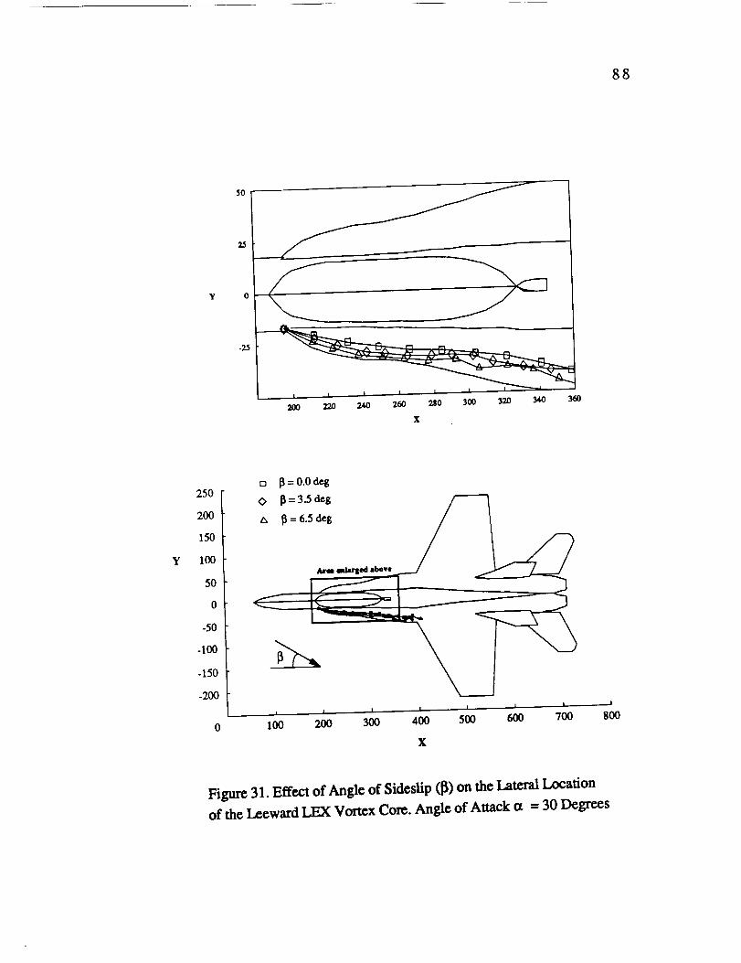
88
5O
Y
23
200 220 240 2_ _0 3_
X
Y
250
2O0
150
100
50
0
-50
-100
-150
-200
___..t___A- -----------J
100 200 300 400 500 600 700 800
X
Figure 31. Effect of Angle of Sideslip ([_) on the Lateral Location
of the Leeward LEX Vortex Core. Angle of Attack cz = 30 Degrees

ORIGINAL PAGE
BLACK AND WHITE PHOTOGRAPH
89
a) Alpha = 15 Degrees; Beta = 0 Degrees
b) Alpha = 15.8 Degrees; Beta = 0.2 Degrees
Figure 32. Comparison of the LEX Vortex Core LocationBetween Water Tunnel and Flight Results

9O
Z
175
150
125
lO0
75
5O i i i i i i i i
180 200 220 _0 260 _0 3_ 3_ 3_ 3_
x
Z
20O
150
100
50
0
0
m_
I I I I I I I
100 200 300 400 500 600 700
X
Figure 33. Comparison of the LEX Vortex Core Vertical Location
Between Water Tunnel and Flight Data. Angle of Attack a = 25 Degrees;
Angle of Sideslip [_= 0 Degrees

/
91
Y
Y
50
40
30
2O
1o
o
-lO
-20
-30
-40
-5O180 200 220 240 260 280 300 320 340 360
X
250
2OO
150
100
50
0
-50
-100
-150
-200
-250| I
0 100 800
wilde8 dx_vc _
I I I I I I
20O 3OO 4OO 5O0 6OO 700
X
Figar¢ 34. Comparison of the LEX Vortex Core Lateral Location
Between Water Tunnel and Flight Data. Angle of Attack a = 25 Degrees;
Angle of SideslipJ3= 0 Degrees
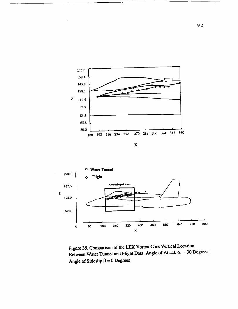
92
z
175.0
159.4
143.8
128.1
112.5
96.9
81.3
65.6
50.0 I I I I I I I I
180 198 216 234 252 270 288 306 324 342 360
X
250.0
187.5
125.0
62.5
ca Water Tunnel
O Right
I I I I I I I I I I
80 160 240 320 400 480 560 640 720 800
X
Figure 35. Comparison of the LEX Vortex Core Vertical Location
Between Water Tunnel and Flight Data. Angle of Attack (x = 30 Degrees;
Angle of Sideslip13= 0 Degrees

93
50.0
37.5
25.0
12.5
y 0
-12.5
-25.0
-37.5
-50.0180 198 216 234 252 270 288 308 324 342 380
x
Y
250.0
187.5
125.0
62.5
0
-62.5
-125.0
-187.5
-250.0 !
0 80O
Water Tunnel
0 Flight /
I I I I I I I I I
80 160 240 320 400 480 560 640 720
X
Figure 36. Comparison of the LEX Vortex Core Lateral Location
Between Water Tunnel and Flight Data. Angle of Attack ot = 30 Degrees;
Angle of Sideslip 13= 0 Degrees

i
J4
ORIGINAL PAGE
BLACK AND WHITE PHOTOGRAPN
94
a) Side View
b) Top View
Figure 37. Location of Forebody Vortices. Alpha = 25 Degrees;
Beta = 0 Degrees

ORIGINAL P,_,GE
BLACK AND WHITE PHOTOGi_APH
95
a) Side View
b) Top View
Figure 38. Location of Forebody Vortices (Effect of Angleof Sideslip). Alpha = 25 Degrees; Beta = 4.0 Degrees

ORIGINAl. P_'_,GE
BI.ACK AND WHt'_E PHOTOGRAPH
96
:_:!
a) 48A Model
b) 48C Model
Figure 39. Location of Forebody Vortices (Effect of ForebodyGeometry). Alpha = 30 Degrees; Beta = 0 Degrees

:L':' _ .L r .,.__
BLACK AP;D WklfTE Fi--IC-[C,'G_/_I. _-, 97
a) 32A Model
b) 48C Model
Figure 40. Location of Forebody Vortices (Effect of ModelScale). Alpha = 25 Degrees; Beta = 0 Degrees

,.'_ * O's 1_ h AOt,I_INAL P,'-,,._r_.
BLACK AND Wt'ilTE FNOTOGRAFH 98
a) 32A Model
b) 48C Model
Figure 41. Location of Forebody Vortices (Effect of ModelScale). Alpha - 30 Degrees; Beta = 0 Degrees

99
-_- 4- +
a) 48A Water Tunnel Model
b) F/A-18 HARV
Figure 42. Comparison of Forebody Vortex Location Between
Water Tunnel and Flight Results [Ref. 23]. Alpha -- 30 Degrees;Beta = 0 Degrees

OR ,'31r,,k_!. PL:';.'_':
b. P,g;_ ANO W.,-IiTE t:;HO;O,'3RAPH100
a) Side View of the Forebody
b) Top View of the Forebody
Figure 43. Forebody Surface Flow Visualization. Alpha = 20
Degrees; Beta = 0 Degrees

101
e9
degrees
180
170
160 '
150 -
140 -
130 "
120
110
100 -
90
71
U I" oha- oo ( "
I:_ 1 1 o Alpha : 34deg
| - J " ! " ! " | " ! " ! " ! " I " • " |
81 91 101 111 121 131 141 151 161 171 181
Fuselage Station, in.
Figure 44. Effect of Angle of Attack on the Locationof the Forebody Primary Separation Line
140
130
120
o
degrees
11o
100
go
• Vel = 3 ird_c (or = 30 deg)
• Vel = 9 L,_ec (o. = 30 dolt,,)
• Vel=3 i.,_¢¢ (am4OdelO
8Om m | m | i
100 120 140 160 180 200
Fuselage Station (in)
Figure 45. Effect of Reynolds Number on the Location ofthe Primary Separation Lines of the Forebody

OP..[G1NAL PAGE
BLACK A,_,_D WHITE PHOTOGRAPH102
Primary Separation Line
a) Water Tunnel Result
0._120 deg
Primary Separation Line
b) CFD Solution
Figure 46. Comparison of the Location of the Primary SeparationLine Between Water Tunnel Results and a Laminar Flow CFD
Prediction [Ref.34]. Alpha = 30 Degrees; Beta = 0 Degrees
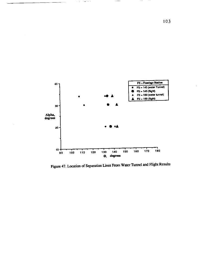
I03
40"
30'
Alpha,degrees
2O
• ,a_lJ_A
• • A
• OAA
I FS = Fmelqie StaXloa
• I_ - 145 (wate¢ Tunnel)
0 FS - 145 (night)• FS - 189 (water funnel)
FS. 189 (flight)
,o .,.,-;-,';''''';''90 100 110 1 0 130 1 0 150 160 1 0 180
0, degrees
Figure 47. Location of Separation Lines From Water Tunnel and Flight Results

104
Alpha(degrees)
60 =
50'
40'
30,
20'
• 1/32du:_Model
MI 1/484calcModel
1/32-S_leModelLEX votmxtnv_down
• "-" 1/48-Scai¢ModelLEX voc_xbreakdown
m
D@
|0 • a • | • I • i • I • I • I
0.2 0.3 0.4 0,5 0.6 0.7 0.6 0.9
X/L
Figure 48. Longitudinal Location of LEX/Forcbody Vortex Interaction andLEX Vortex Breakdown
.Alpha(degrees)
6o
5o
4O
3O
A
AD
0 •
G0
o
• 32A Model
D 48C Mode]
O Flight
A 32A Model (Ref. 23)
20 ! !
0.3 0.4 0_S 016 0.7
X/L
Fisure 49. Longitudinal Location of LEXlForebody Vortex Interaction
From Water Tunnel and Hight Results

/' 105
X/L
0.7"
0.6
0.5
0.4'
0.3IO
! - . | -s _ 4 _ o _ 4]_ (degrees)
Windward Side
Figure 50. Comparison Between Right-measured and Water Tunnel Results ofthe Longitudinal Location of the LEX/Forebody Vortex Interaction as aFunction of the Angle of Sideslip [_(¢z = 33 Degrees)

106
Figure B.1. Location of Cameras and Dimensions Neededfor the Vortex Path Reconstruction Technique

107
CORI_I_"_Off FOR DI_FO'JE_NON
Y_
..........i........._.................................... i.........*.........i................iY,. o.oel _7 + ,.s_, x_Y, _ i i
, ---_._ w-_. Looo.......... ..: i' _I
i i :
Yd
m,
CC_I_'T[ON FOR DIST_YF/GNPlUM VE_
X CCCRZ_DIA_E
'................l...............i................i................................................', .I .... ! !
.] ._ .... ,
-| -1 _
o_:
o.!:
o.o:
-,oA:
•u :
-I.0 '
OOR]I_CT[ON FOR DIwI_r/'[ORvocl
• COORDINATB
o- ........ "....... ._....... $..... "................................. _ .....................
°"...........i........."_........._ ..... _........r ........• .........._.........+.................._-.._.u.o_,_,..._.l ...... 1........J_ ...........
ltA:l. 1.000 JI z : l I l ./ i
. ,
......... i..........•....... *.........:...... _ ................ *.................! ! • i/" !
i i _/r... .... i ..: _ i : i
........i........'...........................i..........-...........,.o .o., .o., -o., .o., o.o o., o., o., o., ,.o
Figure B.2. Relationships Between Distorted (d) and Undistorted (u)Picture Coordinates (All Coordinate Values in Inches)
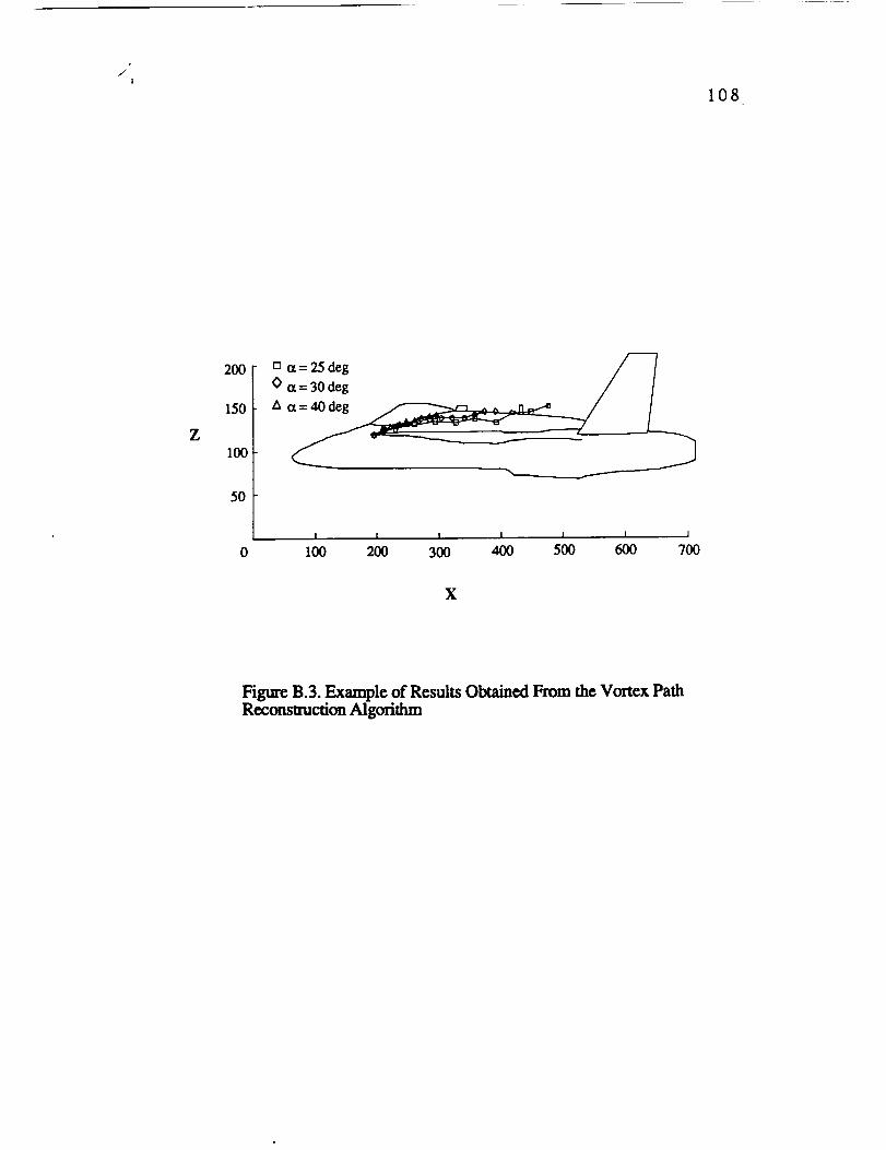
i
/
108
Z
200
150
I00
5O
[] a= 25 deg ,_
(> a=30 deg / /
I I I I I I l
0 1_ 200 3_ 400 5_ 600 7_
X
Figure B.3. Example of Results Obtained From the Vortex PathReconstruction Algorithm