Embed Size (px)
Citation preview
applied sciences
Article
A Waste Heat-Driven Cooling System Based onCombined Organic Rankine and VapourCompression Refrigeration Cycles
Youcai Liang, Zhibin Yu * and Wenguang Li
School of Engineering, University of Glasgow, Glasgow G12 8QQ, UK; [email protected] (Y.L.);[email protected] (W.L.)* Correspondence: [email protected]; Tel.: +44-(0)-141-330-2530
Received: 11 September 2019; Accepted: 9 October 2019; Published: 11 October 2019�����������������
Abstract: In this paper, a heat driven cooling system that essentially integrated an organic Rankinecycle power plant with a vapour compression cycle refrigerator was investigated, aiming to providean alternative to absorption refrigeration systems. The organic Rankine cycle (ORC) subsystemrecovered energy from the exhaust gases of internal combustion engines to produce mechanicalpower. Through a transmission unit, the produced mechanical power was directly used to drive thecompressor of the vapour compression cycle system to produce a refrigeration effect. Unlike the bulkyvapour absorption cooling system, both the ORC power plant and vapour compression refrigeratorcould be scaled down to a few kilowatts, opening the possibility for developing a small-scale wasteheat-driven cooling system that can be widely applied for waste heat recovery from large internalcombustion engines of refrigerated ships, lorries, and trains. In this paper, a model was firstlyestablished to simulate the proposed concept, on the basis of which it was optimized to identify theoptimum operation condition. The results showed that the proposed concept is very promising forthe development of heat-driven cooling systems for recovering waste heat from internal combustionengines’ exhaust gas.
Keywords: organic Rankine cycle; vapour compression cycle; waste heat recovery; marine engine;cascade utilisation
1. Introduction
Internal combustion (IC) engines have been the primary power source for automobiles, long-haultrucks, locomotives, and ships over the past century [1]. Over this time, periods of high fuel costs andconcerns about foreign oil dependence have resulted in increasingly complex engine designs to reducefuel consumption [2]. Although the most efficient mode of the modern large diesel engines is about48–51% efficient in utilising the fuel energy [3], the remainder is still lost as waste to the environmentthrough exhaust gas and jacket water. It appears that developing concepts for utilising the waste heatis important in the area of IC engine application.
Current interest in reducing emissions and engine operating costs has led to the use of efficientwaste heat recovery (WHR). For marine engines, the waste heat was originally used for direct heatingservices, including space heating in winter [4], heavy fuel oil (HFO) heating [5], ballast water heating [6],and hot water supply. However, the heating loads needed for shipboard service on a conventional vesselare usually much less than the available waste heat, resulting in a large amount of heat being unused.
WHR technology for power production was then proposed to be coupled with the powerpropulsion plants or to meet the demand for auxiliary services without additional fuel costs and zeroassociated CO2 emissions. Steam-based WHR systems for both four- and two-stroke marine enginesare available commercially, among others by MAN, ABB, Wärtsilä, Mitsubishi heavy industries, and
Appl. Sci. 2019, 9, 4242; doi:10.3390/app9204242 www.mdpi.com/journal/applsci
Appl. Sci. 2019, 9, 4242 2 of 18
Cummins [3]. Some work on marine WHRs has been reported in the past few years. The workconducted by Theotokatos and Livanos analysed a single pressure steam Rankine cycle (SRC) for amarine engine WHR [7], finding that the WHR is more attractive to combine with two-stroke IC enginethan four-stroke IC engine from an economic perspective [8]. Altosole et al. [9] compared SRC-WHRsof a new design with a retrofitting one on board a passenger ship equipped with diesel–electricpropulsion. Benvenuto et al. [10] studied a dual pressure SRC as a WHR system of a two-stroke dieselengine used for the propulsion of a tanker.
As the exhaust gas temperature of marine engines is usually lower than 370 ◦C, it is economicallyunviable to operate a steam Rankine cycle system [11]. Organic Rankine cycle (ORC) has since beenproposed as an alternative solution for two-stroke engines because of their low exhaust temperatures.Singh [12] conducted a review of different waste heat recovery systems for power generation,including Rankine cycle, Kalina cycle, exhaust gas turbine system, thermoelectric generation system,and the combination of these technologies, focusing on the utilisation of WHR for the supply ofmechanical/electrical power to the ship. Baldi and Gabrielii [13] made comparisons between SRC,ORC, and Kalina cycle for marine WHR, and indicated that ORC produced about 7% additional powerand that the SRC and Kalina cycles produced about 5% additional power. A comparison between ORCand conventional steam Rankine cycle was conducted by Andreasen et al. [14], which showed thatORC has better performance, as higher turbine efficiencies can be achieved for the ORC comparedwith the steam Rankine cycle system. These studies aimed to explore the ORC system’s potential as analternative to SRC and demonstrated its potential to improve fuel efficiency at relatively low engineexhaust temperatures.
Apart from heating and electricity, cooling is also required for food preservation and airconditioning, especially for cruise ships. Thermally powered cooling technologies have gainedconsiderable interest. Liang et al. [15–17] proposed an electricity-cooling combined system (ECCS)for waste heat recovery of marine engines, in which the condensation heat of SRC is used to heatthe generator of the absorption refrigeration cycle. Some scholars proposed to integrate power withcooling cycles, in which the ammonia mixture is used as the working medium [18–20].
In addition to the absorption refrigeration cycle, vapour compression cycle refrigerator is anothertechnology that requires mechanical power/electricity to drive the compressor. Therefore, the conceptof combining ORC and vapour compression cycle (VCC) was proposed as an alternative heat-drivenrefrigeration technology by Prigmore and Barber [21]. Compared to the thermally powered absorptioncooling technologies, the ORC-VCC has some potential advantages in terms of performance andsimplicity. Furthermore, the VCC powered by an ORC can make use of the heat source throughoutthe year [22] to provide either cooling or electricity when cooling is not required [23], increasing theoperational flexibility and improving the economic profitability. Great efforts have been devoted tothe development of ORC-VCC systems since such a concept was proposed. Wali [24,25] comparedthe performance of solar powered ORC-VCC systems for building cooling applications with fivedifferent working fluids. R113 and FC88 were considered as the best working fluids. To reduce thesystem complexity, Aphornratana and Sriveerakul [26] proposed an ORC-VCC concept, of which thecompressor and expander are integrated in the same unit, use the same working fluid, and sharethe same condenser. Bu et al. [27–29] carried out a series of investigations on the working fluid ofORC-VCC ice makers and found that R600 is the most suitable working fluid. An experimental test onthe ORC-VCC system was conducted by Wang [23], and reported a coefficient of performance (COP)of 0.48. Biancardi et al. [30] introduced the design, fabrication, and test of a solar-powered organicRankine cycle heat pump and chiller system capable of delivering 63.3 kW of heating and cooling.When R11 was used as the working fluid, the heating COP of the system ranged from 1.6 to 2.25,while the cooling COP varied between 0.5 and 0.75. In addition to the above studies, several otherresearchers [31–35] have also reported the performance of the ORC-driven VCC for heating purposes.
Despite numerous studies on individual WHR technologies for marine diesel engines, the effectof transmission ratio on the performance of the thermodynamic WHR has not been tackled thus far.
Appl. Sci. 2019, 9, 4242 3 of 18
In this paper, a marine engine waste heat recovery and cooling system with combined ORC and VCCis proposed. A comprehensive energy and exergy analysis was carried out and the potential of theproposed thermodynamic system was demonstrated.
2. Thermodynamics and Operational Conditions of the Proposed System
2.1. System Components
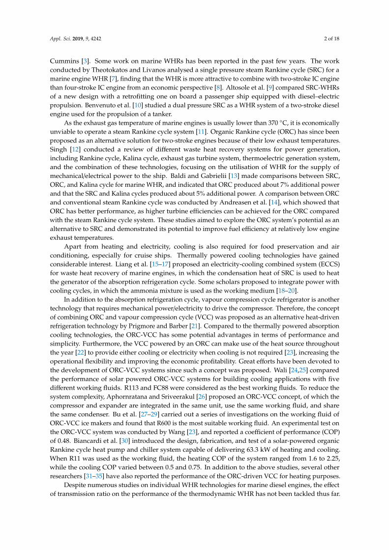
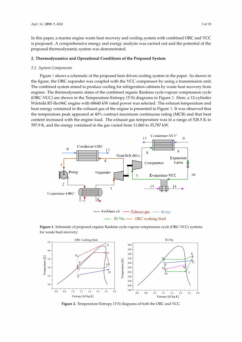
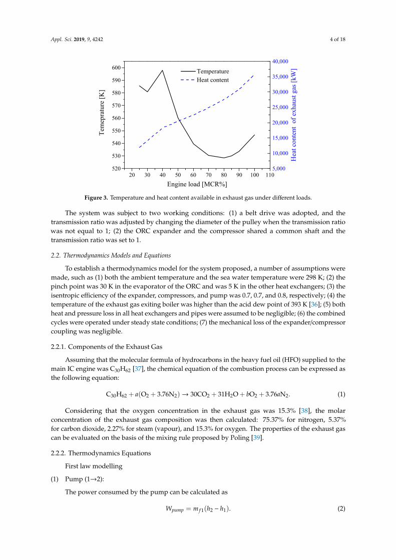
Figure 1 shows a schematic of the proposed heat driven cooling system in the paper. As shown inthe figure, the ORC expander was coupled with the VCC compressor by using a transmission unit.The combined system aimed to produce cooling for refrigeration cabinets by waste heat recovery fromengines. The thermodynamic states of the combined organic Rankine cycle-vapour compression cycle(ORC-VCC) are shown in the Temperature-Entropy (T-S) diagrams in Figure 2. Here, a 12-cylinderWärtsilä RT-flex96C engine with 68640 kW rated power was selected. The exhaust temperature andheat energy contained in the exhaust gas of the engine is presented in Figure 3. It was observed thatthe temperature peak appeared at 40% contract maximum continuous rating (MCR) and that heatcontent increased with the engine load. The exhaust gas temperature was in a range of 528.5 K to597.9 K, and the energy contained in the gas varied from 11,860 to 35,787 kW.
Appl. Sci. 2019, 9, x FOR PEER REVIEW 3 of 20
Despite numerous studies on individual WHR technologies for marine diesel engines, the effect of transmission ratio on the performance of the thermodynamic WHR has not been tackled thus far. In this paper, a marine engine waste heat recovery and cooling system with combined ORC and VCC is proposed. A comprehensive energy and exergy analysis was carried out and the potential of the proposed thermodynamic system was demonstrated.
2. Thermodynamics and Operational Conditions of the Proposed System
2.1. System Components
Figure 1 shows a schematic of the proposed heat driven cooling system in the paper. As shown in the figure, the ORC expander was coupled with the VCC compressor by using a transmission unit. The combined system aimed to produce cooling for refrigeration cabinets by waste heat recovery from engines. The thermodynamic states of the combined organic Rankine cycle-vapour compression cycle (ORC-VCC) are shown in the Temperature-Entropy (T-S) diagrams in Figure 2. Here, a 12-cylinder Wärtsilä RT-flex96C engine with 68640 kW rated power was selected. The exhaust temperature and heat energy contained in the exhaust gas of the engine is presented in Figure 3. It was observed that the temperature peak appeared at 40% contract maximum continuous rating (MCR) and that heat content increased with the engine load. The exhaust gas temperature was in a range of 528.5 K to 597.9 K, and the energy contained in the gas varied from 11,860 to 35,787 kW.
Figure 1. Schematic of proposed organic Rankine cycle-vapour compression cycle (ORC-VCC) systems for waste heat recovery.
0.6 0.8 1.0 1.2 1.4 1.6 1.8 2.0
200
250
300
350
400
450ORC working fluid
4
3
2
112
0
6
Tem
pera
ture
[K]
Entropy [kJ/kg⋅K]
5
0.6 0.8 1.0 1.2 1.4 1.6 1.8 2.0
180
200
220
240
260
280
300
320
340
360
380
R134a
Entropy [kJ/kg⋅K]
13 12
110
8
10
8
Tem
pera
ture
[K]
7
Figure 1. Schematic of proposed organic Rankine cycle-vapour compression cycle (ORC-VCC) systemsfor waste heat recovery.
Appl. Sci. 2019, 9, x FOR PEER REVIEW 3 of 20
Despite numerous studies on individual WHR technologies for marine diesel engines, the effect of transmission ratio on the performance of the thermodynamic WHR has not been tackled thus far. In this paper, a marine engine waste heat recovery and cooling system with combined ORC and VCC is proposed. A comprehensive energy and exergy analysis was carried out and the potential of the proposed thermodynamic system was demonstrated.
2. Thermodynamics and Operational Conditions of the Proposed System
2.1. System Components
Figure 1 shows a schematic of the proposed heat driven cooling system in the paper. As shown in the figure, the ORC expander was coupled with the VCC compressor by using a transmission unit. The combined system aimed to produce cooling for refrigeration cabinets by waste heat recovery from engines. The thermodynamic states of the combined organic Rankine cycle-vapour compression cycle (ORC-VCC) are shown in the Temperature-Entropy (T-S) diagrams in Figure 2. Here, a 12-cylinder Wärtsilä RT-flex96C engine with 68640 kW rated power was selected. The exhaust temperature and heat energy contained in the exhaust gas of the engine is presented in Figure 3. It was observed that the temperature peak appeared at 40% contract maximum continuous rating (MCR) and that heat content increased with the engine load. The exhaust gas temperature was in a range of 528.5 K to 597.9 K, and the energy contained in the gas varied from 11,860 to 35,787 kW.
Figure 1. Schematic of proposed organic Rankine cycle-vapour compression cycle (ORC-VCC) systems for waste heat recovery.
0.6 0.8 1.0 1.2 1.4 1.6 1.8 2.0
200
250
300
350
400
450ORC working fluid
4
3
2
112
0
6
Tem
pera
ture
[K]
Entropy [kJ/kg⋅K]
5
0.6 0.8 1.0 1.2 1.4 1.6 1.8 2.0
180
200
220
240
260
280
300
320
340
360
380
R134a
Entropy [kJ/kg⋅K]
13 12
110
8
10
8
Tem
pera
ture
[K]
7
Figure 2. Temperature-Entropy (T-S) diagrams of both the ORC and VCC.
Appl. Sci. 2019, 9, 4242 4 of 18
Appl. Sci. 2019, 9, x FOR PEER REVIEW 4 of 20
Figure 2. Temperature-Entropy (T-S) diagrams of both the ORC and VCC.
20 30 40 50 60 70 80 90 100 110520
530
540
550
560
570
580
590
600
Tem
epra
ture
[K]
Engine load [MCR%]
Temperature
5,000
10,000
15,000
20,000
25,000
30,000
35,000
40,000
Heat content
Hea
t con
tent
of e
xhau
st ga
s [kW
]
Figure 3. Temperature and heat content available in exhaust gas under different loads.
The system was subject to two working conditions: (1) a belt drive was adopted, and the transmission ratio was adjusted by changing the diameter of the pulley when the transmission ratio was not equal to 1; (2) the ORC expander and the compressor shared a common shaft and the transmission ratio was set to 1.
2.2. Thermodynamics Models and Equations
To establish a thermodynamics model for the system proposed, a number of assumptions were made, such as (1) both the ambient temperature and the sea water temperature were 298 K; (2) the pinch point was 30 K in the evaporator of the ORC and was 5 K in the other heat exchangers; (3) the isentropic efficiency of the expander, compressors, and pump was 0.7, 0.7, and 0.8, respectively; (4) the temperature of the exhaust gas exiting boiler was higher than the acid dew point of 393 K [36]; (5) both heat and pressure loss in all heat exchangers and pipes were assumed to be negligible; (6) the combined cycles were operated under steady state conditions; (7) the mechanical loss of the expander/compressor coupling was negligible.
2.2.1. Components of the Exhaust Gas
Assuming that the molecular formula of hydrocarbons in the heavy fuel oil (HFO) supplied to the main IC engine was C30H62 [37], the chemical equation of the combustion process can be expressed as the following equation:
2222226230 76.33130)76.3( aNbOOHCONOaHC +++→++ . (1)
Considering that the oxygen concentration in the exhaust gas was 15.3% [38], the molar concentration of the exhaust gas composition was then calculated: 75.37% for nitrogen, 5.37% for carbon dioxide, 2.27% for steam (vapour), and 15.3% for oxygen. The properties of the exhaust gas can be evaluated on the basis of the mixing rule proposed by Poling [39].
2.2.2. Thermodynamics Equations
First law modelling
Figure 3. Temperature and heat content available in exhaust gas under different loads.
The system was subject to two working conditions: (1) a belt drive was adopted, and thetransmission ratio was adjusted by changing the diameter of the pulley when the transmission ratiowas not equal to 1; (2) the ORC expander and the compressor shared a common shaft and thetransmission ratio was set to 1.
2.2. Thermodynamics Models and Equations
To establish a thermodynamics model for the system proposed, a number of assumptions weremade, such as (1) both the ambient temperature and the sea water temperature were 298 K; (2) thepinch point was 30 K in the evaporator of the ORC and was 5 K in the other heat exchangers; (3) theisentropic efficiency of the expander, compressors, and pump was 0.7, 0.7, and 0.8, respectively; (4) thetemperature of the exhaust gas exiting boiler was higher than the acid dew point of 393 K [36]; (5) bothheat and pressure loss in all heat exchangers and pipes were assumed to be negligible; (6) the combinedcycles were operated under steady state conditions; (7) the mechanical loss of the expander/compressorcoupling was negligible.
2.2.1. Components of the Exhaust Gas
Assuming that the molecular formula of hydrocarbons in the heavy fuel oil (HFO) supplied to themain IC engine was C30H62 [37], the chemical equation of the combustion process can be expressed asthe following equation:
C30H62 + a(O2 + 3.76N2)→ 30CO2 + 31H2O + bO2 + 3.76aN2. (1)
Considering that the oxygen concentration in the exhaust gas was 15.3% [38], the molarconcentration of the exhaust gas composition was then calculated: 75.37% for nitrogen, 5.37%for carbon dioxide, 2.27% for steam (vapour), and 15.3% for oxygen. The properties of the exhaust gascan be evaluated on the basis of the mixing rule proposed by Poling [39].
2.2.2. Thermodynamics Equations
First law modelling
(1) Pump (1→2):
The power consumed by the pump can be calculated as
Wpump = m f 1(h2 − h1). (2)
Appl. Sci. 2019, 9, 4242 5 of 18
The isentropic efficiency of the pump can be calculated as
ηpump,is =h2is − h1
h2 − h1. (3)
(2) Evaporator-ORC (2→3, 5→6):
The heat transferred in the evaporator-ORC can be calculated as
Qeva,ORC = m f 1(h3 − h2), (4)
Qeva,ORC = mg(h5 − h6). (5)
(3) Expander (3→4):
The power generated in the expander can be calculated as
Wexp = m f 1(h3 − h4). (6)
The isentropic efficiency of the expander can be calculated as
ηexp,is =h3 − h4
h3 − h4is. (7)
(4) Condenser-ORC (4→1, 0→12):
The heat transferred in condenser-ORC can be calculated as
Qcond,ORC = m f 1(h4 − h1), (8)
Qcond,ORC = mw1(h12 − h0). (9)
(5) Compressor (7→8):
The power consumed by compressor can be calculated as
Wcom = m f 2(h8 − h7), (10)
Wcom = Wexp. (11)
The isentropic efficiency of the compressor can be calculated as
ηcom,is =h8is − h7
h8 − h7. (12)
(6) Condenser-VCC (8→9, 0→11):
The heat transferred in the condenser-VCC can be calculated as
Qcond,VCC = m f 2(h8 − h9), (13)
Qcond,VCC = mw2(h11 − h0). (14)
(7) Expansion valve (9→10):
The working fluid flowing through the expansion valve can be taken as an isenthalpicthrottling process
h9 = h10. (15)
Appl. Sci. 2019, 9, 4242 6 of 18
(8) Evaporator-VCC (10→7, 13→14):
The heat transferred in the evaporator-ORC can be calculated as
Qeva,VCC = m f 2(h7 − h10), (16)
Qeva,VCC = mair(h13 − h14). (17)
Second law efficiencyThe exergy at state point i in the system can be defined by
Ei = m f [(hi − h0) − T0(si − s0)]. (18)
The exergy destruction caused in each component can be calculated as
Ii =∑
Ein −∑
Eout. (19)
Expressions for exergy destruction are shown in following:Pump-ORC:
Ipump,ORC = Wpump + E1 − E2. (20)
Evaporator-ORC:Ieva,ORC = E5 + E2 − (E6 + E3). (21)
Expander-ORC:Iexp,ORC = E3 − E4 −Wexp. (22)
Condenser-ORC:Icond,ORC = E0 + E4 − (E1 + E12). (23)
Compressor-VCC:Icom,VCC = Wcom + E7 − E8. (24)
Condenser-VCC:Icond,VCC = E8 + E0 − (E11 + E9). (25)
Expansion Valve:Ival,VCC = E9 − E10. (26)
Evaporator-VCC:Ieva,VCC = E10 + E13 − (E7 + E14). (27)
The total exergy destruction caused in this system can be expressed as
Itotal = Ieva,ORC + Iexp,ORC + Ipump,ORC + Icond,ORC + Icond,VCC + Ival,VCC + Ieva,VCC + Icom,VCC. (28)
The exergy efficiency of the ORC-VCC waste heat recovery system can be calculated asthe following:
ηex−WHR = Eout/Ein. (29)
In this case, the exergy input Ein included the exergy difference of exhaust gas stream, the powerof the pump.
Eout = (T0/Tcabin,in − 1)Qeva−VCC, (30)
Ein = Eexh + WPump. (31)
Appl. Sci. 2019, 9, 4242 7 of 18
The term EER (energy efficiency ratio) is a ratio of the useful cooling provided to the work requiredof air conditioners. Higher EER equates to lower operating costs.
EER =Qeva,VCC
Wexp. (32)
2.3. Operational Conditions
The heat transfer process should meet two requirements simultaneously. Firstly, the pinch pointtemperature difference (PPTD) should not be lower than 30 K in the modelling of ORC evaporatorduring the phase change process to ensure the feasible heat exchanger design in practical applications.Furthermore, the exhaust gas temperature should be higher than the acid dew point to avoid thepossible corrosion in the evaporator (exhaust side), which is normally taken to be 393 K [40,41].
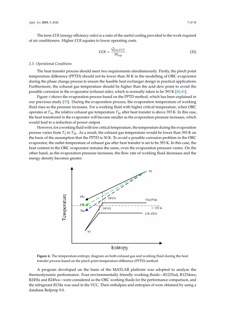
Figure 4 shows the evaporation process based on the PPTD method, which has been explained inour previous study [35]. During the evaporation process, the evaporation temperature of workingfluid rises as the pressure increases. For a working fluid with higher critical temperature, when ORCoperates at T3a, the relative exhaust gas temperature T6a after heat transfer is above 393 K. In this case,the heat transferred in the evaporator will become smaller as the evaporation pressure increases, whichwould lead to a reduction of power output.
However, for a working fluid with low critical temperature, the temperature during the evaporationprocess varies from T2 to T3b. As a result, the exhaust gas temperature would be lower than 393 K onthe basis of the assumption that the PPTD is 30 K. To avoid a possible corrosion problem in the ORCevaporator, the outlet temperature of exhaust gas after heat transfer is set to be 393 K. In this case, theheat content in the ORC evaporator remains the same, even the evaporation pressure varies. On theother hand, as the evaporation pressure increases, the flow rate of working fluid decreases and theenergy density becomes greater.Appl. Sci. 2019, 9, x FOR PEER REVIEW 8 of 20
Figure 4. The temperature-entropy diagram on both exhaust gas and working fluid during the heat transfer process based on the pinch point temperature difference (PPTD) method.
A program developed on the basis of the MATLAB platform was adopted to analyse the thermodynamic performance. Four environmentally friendly working fluids—R1233zd, R1234zez, R245fa and R245ca—were considered as the ORC working fluids for the performance comparison, and the refrigerant R134a was used in the VCC. Their enthalpies and entropies of were obtained by using a database Refprop 9.0.
3. Results
3.1. Belt Drive as the Transmission Unit
When a belt drive was used as the transmission unit for the coupling of expander and compressor, both the ORC and VCC could be operated at their optimum conditions simultaneously. In this case, the transmission ratio could be adjusted by changing the diameters of two pulleys.
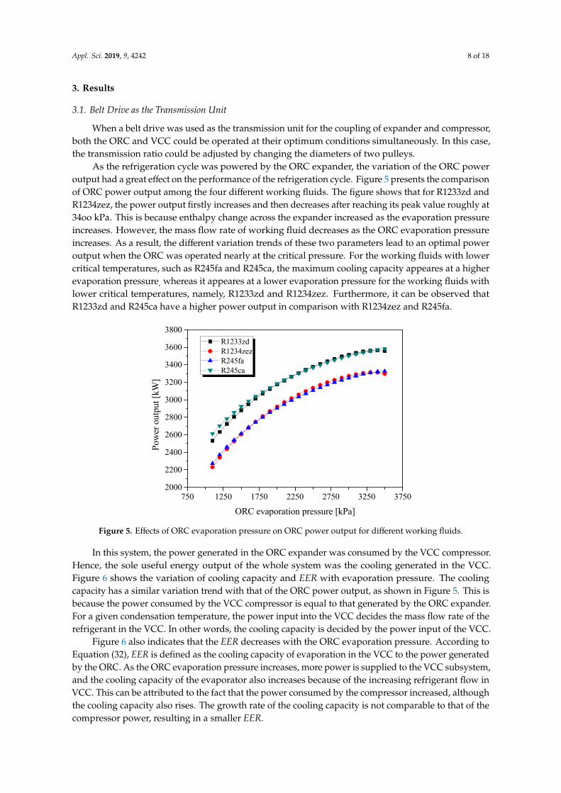
As the refrigeration cycle was powered by the ORC expander, the variation of the ORC power output had a great effect on the performance of the refrigeration cycle. Figure 5 presents the comparison of ORC power output among the four different working fluids. The figure shows that for R1233zd and R1234zez, the power output firstly increases and then decreases after reaching its peak value roughly at 34oo kPa. This is because enthalpy change across the expander increased as the evaporation pressure increases. However, the mass flow rate of working fluid decreases as the ORC evaporation pressure increases. As a result, the different variation trends of these two parameters lead to an optimal power output when the ORC was operated nearly at the critical pressure. For the working fluids with lower critical temperatures, such as R245fa and R245ca, the maximum cooling capacity appeares at a higher evaporation pressure, whereas it appeares at a lower evaporation pressure for the working fluids with lower critical temperatures, namely, R1233zd and R1234zez. Furthermore, it can be observed that R1233zd and R245ca have a higher power output in comparison with R1234zez and R245fa.
Figure 4. The temperature-entropy diagram on both exhaust gas and working fluid during the heattransfer process based on the pinch point temperature difference (PPTD) method.
A program developed on the basis of the MATLAB platform was adopted to analyse thethermodynamic performance. Four environmentally friendly working fluids—R1233zd, R1234zez,R245fa and R245ca—were considered as the ORC working fluids for the performance comparison, andthe refrigerant R134a was used in the VCC. Their enthalpies and entropies of were obtained by using adatabase Refprop 9.0.
Appl. Sci. 2019, 9, 4242 8 of 18
3. Results
3.1. Belt Drive as the Transmission Unit
When a belt drive was used as the transmission unit for the coupling of expander and compressor,both the ORC and VCC could be operated at their optimum conditions simultaneously. In this case,the transmission ratio could be adjusted by changing the diameters of two pulleys.
As the refrigeration cycle was powered by the ORC expander, the variation of the ORC poweroutput had a great effect on the performance of the refrigeration cycle. Figure 5 presents the comparisonof ORC power output among the four different working fluids. The figure shows that for R1233zd andR1234zez, the power output firstly increases and then decreases after reaching its peak value roughly at34oo kPa. This is because enthalpy change across the expander increased as the evaporation pressureincreases. However, the mass flow rate of working fluid decreases as the ORC evaporation pressureincreases. As a result, the different variation trends of these two parameters lead to an optimal poweroutput when the ORC was operated nearly at the critical pressure. For the working fluids with lowercritical temperatures, such as R245fa and R245ca, the maximum cooling capacity appeares at a higherevaporation pressure, whereas it appeares at a lower evaporation pressure for the working fluids withlower critical temperatures, namely, R1233zd and R1234zez. Furthermore, it can be observed thatR1233zd and R245ca have a higher power output in comparison with R1234zez and R245fa.
Appl. Sci. 2019, 9, x FOR PEER REVIEW 9 of 20
750 1250 1750 2250 2750 3250 37502000
2200
2400
2600
2800
3000
3200
3400
3600
3800
Pow
er o
utpu
t [kW
]
ORC evaporation pressure [kPa]
R1233zd R1234zez R245fa R245ca
Figure 5. Effects of ORC evaporation pressure on ORC power output for different working fluids.
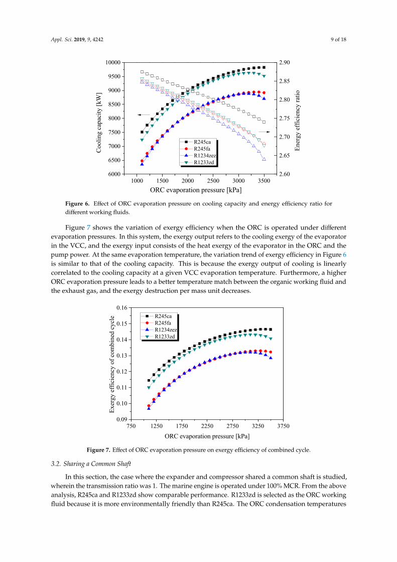
In this system, the power generated in the ORC expander was consumed by the VCC compressor. Hence, the sole useful energy output of the whole system was the cooling generated in the VCC. Figure 6 shows the variation of cooling capacity and EER with evaporation pressure. The cooling capacity has a similar variation trend with that of the ORC power output, as shown in Figure 5. This is because the power consumed by the VCC compressor is equal to that generated by the ORC expander. For a given condensation temperature, the power input into the VCC decides the mass flow rate of the refrigerant in the VCC. In other words, the cooling capacity is decided by the power input of the VCC.
Figure 6 also indicates that the EER decreases with the ORC evaporation pressure. According to Equation (32), EER is defined as the cooling capacity of evaporation in the VCC to the power generated by the ORC. As the ORC evaporation pressure increases, more power is supplied to the VCC subsystem, and the cooling capacity of the evaporator also increases because of the increasing refrigerant flow in VCC. This can be attributed to the fact that the power consumed by the compressor increased, although the cooling capacity also rises. The growth rate of the cooling capacity is not comparable to that of the compressor power, resulting in a smaller EER.
Figure 5. Effects of ORC evaporation pressure on ORC power output for different working fluids.
In this system, the power generated in the ORC expander was consumed by the VCC compressor.Hence, the sole useful energy output of the whole system was the cooling generated in the VCC.Figure 6 shows the variation of cooling capacity and EER with evaporation pressure. The coolingcapacity has a similar variation trend with that of the ORC power output, as shown in Figure 5. This isbecause the power consumed by the VCC compressor is equal to that generated by the ORC expander.For a given condensation temperature, the power input into the VCC decides the mass flow rate of therefrigerant in the VCC. In other words, the cooling capacity is decided by the power input of the VCC.
Figure 6 also indicates that the EER decreases with the ORC evaporation pressure. According toEquation (32), EER is defined as the cooling capacity of evaporation in the VCC to the power generatedby the ORC. As the ORC evaporation pressure increases, more power is supplied to the VCC subsystem,and the cooling capacity of the evaporator also increases because of the increasing refrigerant flow inVCC. This can be attributed to the fact that the power consumed by the compressor increased, althoughthe cooling capacity also rises. The growth rate of the cooling capacity is not comparable to that of thecompressor power, resulting in a smaller EER.
Appl. Sci. 2019, 9, 4242 9 of 18Appl. Sci. 2019, 9, x FOR PEER REVIEW 10 of 20
1000 1500 2000 2500 3000 35006000
6500
7000
7500
8000
8500
9000
9500
10000
Ener
gy e
ffici
ency
ratio
Cool
ing
capa
city
[kW
]
ORC evaporation pressure [kPa]
R245ca R245fa R1234zez R1233zd
2.60
2.65
2.70
2.75
2.80
2.85
2.90
Figure 6. Effect of ORC evaporation pressure on cooling capacity and energy efficiency ratio for different working fluids.
Figure 7 shows the variation of exergy efficiency when the ORC is operated under different evaporation pressures. In this system, the exergy output refers to the cooling exergy of the evaporator in the VCC, and the exergy input consists of the heat exergy of the evaporator in the ORC and the pump power. At the same evaporation temperature, the variation trend of exergy efficiency in Figure 6 is similar to that of the cooling capacity. This is because the exergy output of cooling is linearly correlated to the cooling capacity at a given VCC evaporation temperature. Furthermore, a higher ORC evaporation pressure leads to a better temperature match between the organic working fluid and the exhaust gas, and the exergy destruction per mass unit decreases.
750 1250 1750 2250 2750 3250 37500.09
0.10
0.11
0.12
0.13
0.14
0.15
0.16
Exer
gy e
ffici
ency
of c
ombi
ned
cycl
e
ORC evaporation pressure [kPa]
R245ca R245fa R1234zez R1233zd
Figure 7. Effect of ORC evaporation pressure on exergy efficiency of combined cycle.
Figure 6. Effect of ORC evaporation pressure on cooling capacity and energy efficiency ratio fordifferent working fluids.
Figure 7 shows the variation of exergy efficiency when the ORC is operated under differentevaporation pressures. In this system, the exergy output refers to the cooling exergy of the evaporatorin the VCC, and the exergy input consists of the heat exergy of the evaporator in the ORC and thepump power. At the same evaporation temperature, the variation trend of exergy efficiency in Figure 6is similar to that of the cooling capacity. This is because the exergy output of cooling is linearlycorrelated to the cooling capacity at a given VCC evaporation temperature. Furthermore, a higherORC evaporation pressure leads to a better temperature match between the organic working fluid andthe exhaust gas, and the exergy destruction per mass unit decreases.
Appl. Sci. 2019, 9, x FOR PEER REVIEW 10 of 20
1000 1500 2000 2500 3000 35006000
6500
7000
7500
8000
8500
9000
9500
10000
Ener
gy e
ffici
ency
ratio
Cool
ing
capa
city
[kW
]
ORC evaporation pressure [kPa]
R245ca R245fa R1234zez R1233zd
2.60
2.65
2.70
2.75
2.80
2.85
2.90
Figure 6. Effect of ORC evaporation pressure on cooling capacity and energy efficiency ratio for different working fluids.
Figure 7 shows the variation of exergy efficiency when the ORC is operated under different evaporation pressures. In this system, the exergy output refers to the cooling exergy of the evaporator in the VCC, and the exergy input consists of the heat exergy of the evaporator in the ORC and the pump power. At the same evaporation temperature, the variation trend of exergy efficiency in Figure 6 is similar to that of the cooling capacity. This is because the exergy output of cooling is linearly correlated to the cooling capacity at a given VCC evaporation temperature. Furthermore, a higher ORC evaporation pressure leads to a better temperature match between the organic working fluid and the exhaust gas, and the exergy destruction per mass unit decreases.
750 1250 1750 2250 2750 3250 37500.09
0.10
0.11
0.12
0.13
0.14
0.15
0.16
Exer
gy e
ffici
ency
of c
ombi
ned
cycl
e
ORC evaporation pressure [kPa]
R245ca R245fa R1234zez R1233zd
Figure 7. Effect of ORC evaporation pressure on exergy efficiency of combined cycle.
Figure 7. Effect of ORC evaporation pressure on exergy efficiency of combined cycle.
3.2. Sharing a Common Shaft
In this section, the case where the expander and compressor shared a common shaft is studied,wherein the transmission ratio was 1. The marine engine is operated under 100% MCR. From the aboveanalysis, R245ca and R1233zd show comparable performance. R1233zd is selected as the ORC workingfluid because it is more environmentally friendly than R245ca. The ORC condensation temperatures
Appl. Sci. 2019, 9, 4242 10 of 18
are set as 308 K by using sea water as the heat sink. In this system, the pressure difference across theexpander is equal to that across the compressor (P3-P4 = P8-P7).
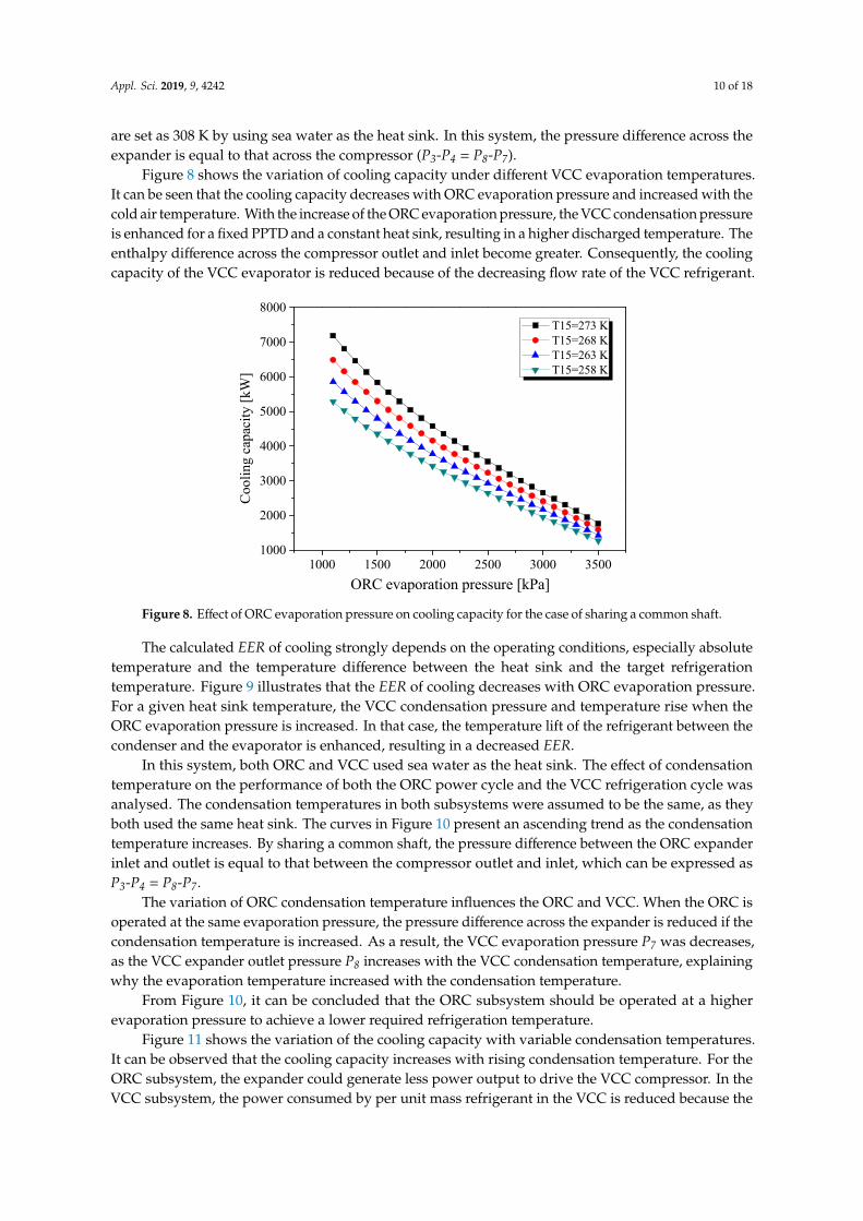
Figure 8 shows the variation of cooling capacity under different VCC evaporation temperatures.It can be seen that the cooling capacity decreases with ORC evaporation pressure and increased with thecold air temperature. With the increase of the ORC evaporation pressure, the VCC condensation pressureis enhanced for a fixed PPTD and a constant heat sink, resulting in a higher discharged temperature. Theenthalpy difference across the compressor outlet and inlet become greater. Consequently, the coolingcapacity of the VCC evaporator is reduced because of the decreasing flow rate of the VCC refrigerant.
Appl. Sci. 2019, 9, x FOR PEER REVIEW 11 of 20
3.2. Sharing a Common Shaft
In this section, the case where the expander and compressor shared a common shaft is studied, wherein the transmission ratio was 1. The marine engine is operated under 100% MCR. From the above analysis, R245ca and R1233zd show comparable performance. R1233zd is selected as the ORC working fluid because it is more environmentally friendly than R245ca. The ORC condensation temperatures are set as 308 K by using sea water as the heat sink. In this system, the pressure difference across the expander is equal to that across the compressor (P3-P4 = P8-P7).
Figure 8 shows the variation of cooling capacity under different VCC evaporation temperatures. It can be seen that the cooling capacity decreases with ORC evaporation pressure and increased with the cold air temperature. With the increase of the ORC evaporation pressure, the VCC condensation pressure is enhanced for a fixed PPTD and a constant heat sink, resulting in a higher discharged temperature. The enthalpy difference across the compressor outlet and inlet become greater. Consequently, the cooling capacity of the VCC evaporator is reduced because of the decreasing flow rate of the VCC refrigerant.
1000 1500 2000 2500 3000 35001000
2000
3000
4000
5000
6000
7000
8000
Cool
ing
capa
city
[kW
]
ORC evaporation pressure [kPa]
T15=273 K T15=268 K T15=263 K T15=258 K
Figure 8. Effect of ORC evaporation pressure on cooling capacity for the case of sharing a common shaft.
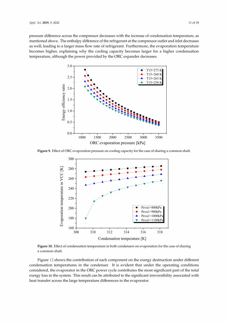
The calculated EER of cooling strongly depends on the operating conditions, especially absolute temperature and the temperature difference between the heat sink and the target refrigeration temperature. Figure 9 illustrates that the EER of cooling decreases with ORC evaporation pressure. For a given heat sink temperature, the VCC condensation pressure and temperature rise when the ORC evaporation pressure is increased. In that case, the temperature lift of the refrigerant between the condenser and the evaporator is enhanced, resulting in a decreased EER.
Figure 8. Effect of ORC evaporation pressure on cooling capacity for the case of sharing a common shaft.
The calculated EER of cooling strongly depends on the operating conditions, especially absolutetemperature and the temperature difference between the heat sink and the target refrigerationtemperature. Figure 9 illustrates that the EER of cooling decreases with ORC evaporation pressure.For a given heat sink temperature, the VCC condensation pressure and temperature rise when theORC evaporation pressure is increased. In that case, the temperature lift of the refrigerant between thecondenser and the evaporator is enhanced, resulting in a decreased EER.
In this system, both ORC and VCC used sea water as the heat sink. The effect of condensationtemperature on the performance of both the ORC power cycle and the VCC refrigeration cycle wasanalysed. The condensation temperatures in both subsystems were assumed to be the same, as theyboth used the same heat sink. The curves in Figure 10 present an ascending trend as the condensationtemperature increases. By sharing a common shaft, the pressure difference between the ORC expanderinlet and outlet is equal to that between the compressor outlet and inlet, which can be expressed asP3-P4 = P8-P7.
The variation of ORC condensation temperature influences the ORC and VCC. When the ORC isoperated at the same evaporation pressure, the pressure difference across the expander is reduced if thecondensation temperature is increased. As a result, the VCC evaporation pressure P7 was decreases,as the VCC expander outlet pressure P8 increases with the VCC condensation temperature, explainingwhy the evaporation temperature increased with the condensation temperature.
From Figure 10, it can be concluded that the ORC subsystem should be operated at a higherevaporation pressure to achieve a lower required refrigeration temperature.
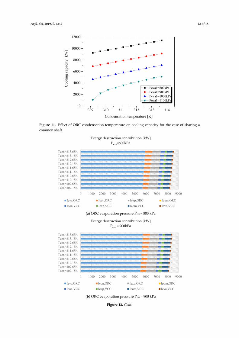
Figure 11 shows the variation of the cooling capacity with variable condensation temperatures.It can be observed that the cooling capacity increases with rising condensation temperature. For theORC subsystem, the expander could generate less power output to drive the VCC compressor. In theVCC subsystem, the power consumed by per unit mass refrigerant in the VCC is reduced because the
Appl. Sci. 2019, 9, 4242 11 of 18
pressure difference across the compressor decreases with the increase of condensation temperature, asmentioned above. The enthalpy difference of the refrigerant at the compressor outlet and inlet decreasesas well, leading to a larger mass flow rate of refrigerant. Furthermore, the evaporation temperaturebecomes higher, explaining why the cooling capacity becomes larger for a higher condensationtemperature, although the power provided by the ORC expander decreases.
Appl. Sci. 2019, 9, x FOR PEER REVIEW 12 of 20
1000 1500 2000 2500 3000 35000.0
0.5
1.0
1.5
2.0
2.5
3.0
En
ergy
effi
cien
cy ra
tio
ORC evaporation pressure [kPa]
T15=273 K T15=268 K T15=263 K T15=258 K
Figure 9. Effect of ORC evaporation pressure on cooling capacity for the case of sharing a common shaft.
In this system, both ORC and VCC used sea water as the heat sink. The effect of condensation temperature on the performance of both the ORC power cycle and the VCC refrigeration cycle was analysed. The condensation temperatures in both subsystems were assumed to be the same, as they both used the same heat sink. The curves in Figure 10 present an ascending trend as the condensation temperature increases. By sharing a common shaft, the pressure difference between the ORC expander inlet and outlet is equal to that between the compressor outlet and inlet, which can be expressed as P3-P4 = P8-P7.
The variation of ORC condensation temperature influences the ORC and VCC. When the ORC is operated at the same evaporation pressure, the pressure difference across the expander is reduced if the condensation temperature is increased. As a result, the VCC evaporation pressure P7 was decreases, as the VCC expander outlet pressure P8 increases with the VCC condensation temperature, explaining why the evaporation temperature increased with the condensation temperature.
From Figure 10, it can be concluded that the ORC subsystem should be operated at a higher evaporation pressure to achieve a lower required refrigeration temperature.
Figure 9. Effect of ORC evaporation pressure on cooling capacity for the case of sharing a common shaft.
Appl. Sci. 2019, 9, x FOR PEER REVIEW 13 of 20
308 310 312 314 316 318160
180
200
220
240
260
280
300
Evap
orat
ion
tem
pera
ture
in V
CC [K
]
Condensation temperature [K]
Peva1=800kPa Peva1=900kPa Peva1=1000kPa Peva1=1100kPa
Figure 10. Effect of condensation temperature in both condensers on evaporation for the case of sharing a common shaft.
Figure 11 shows the variation of the cooling capacity with variable condensation temperatures. It can be observed that the cooling capacity increases with rising condensation temperature. For the ORC subsystem, the expander could generate less power output to drive the VCC compressor. In the VCC subsystem, the power consumed by per unit mass refrigerant in the VCC is reduced because the pressure difference across the compressor decreases with the increase of condensation temperature, as mentioned above. The enthalpy difference of the refrigerant at the compressor outlet and inlet decreases as well, leading to a larger mass flow rate of refrigerant. Furthermore, the evaporation temperature becomes higher, explaining why the cooling capacity becomes larger for a higher condensation temperature, although the power provided by the ORC expander decreases.
309 310 311 312 313 3140
2000
4000
6000
8000
10000
12000
Cool
ing
capa
city
[kW
]
Condensation temperature [K]
Peva1=800kPa Peva1=900kPa Peva1=1000kPa Peva1=1100kPa
Figure 11. Effect of ORC condensation temperature on cooling capacity for the case of sharing a common shaft.
Figure 10. Effect of condensation temperature in both condensers on evaporation for the case of sharinga common shaft.
Figure 12 shows the contribution of each component on the exergy destruction under differentcondensation temperatures in the condenser. It is evident that under the operating conditionsconsidered, the evaporator in the ORC power cycle contributes the most significant part of the totalexergy loss in the system. This result can be attributed to the significant irreversibility associated withheat transfer across the large temperature differences in the evaporator.
Appl. Sci. 2019, 9, 4242 12 of 18
Appl. Sci. 2019, 9, x FOR PEER REVIEW 13 of 20
308 310 312 314 316 318160
180
200
220
240
260
280
300
Evap
orat
ion
tem
pera
ture
in V
CC [K
]
Condensation temperature [K]
Peva1=800kPa Peva1=900kPa Peva1=1000kPa Peva1=1100kPa
Figure 10. Effect of condensation temperature in both condensers on evaporation for the case of sharing a common shaft.
Figure 11 shows the variation of the cooling capacity with variable condensation temperatures. It can be observed that the cooling capacity increases with rising condensation temperature. For the ORC subsystem, the expander could generate less power output to drive the VCC compressor. In the VCC subsystem, the power consumed by per unit mass refrigerant in the VCC is reduced because the pressure difference across the compressor decreases with the increase of condensation temperature, as mentioned above. The enthalpy difference of the refrigerant at the compressor outlet and inlet decreases as well, leading to a larger mass flow rate of refrigerant. Furthermore, the evaporation temperature becomes higher, explaining why the cooling capacity becomes larger for a higher condensation temperature, although the power provided by the ORC expander decreases.
309 310 311 312 313 3140
2000
4000
6000
8000
10000
12000
Cool
ing
capa
city
[kW
]
Condensation temperature [K]
Peva1=800kPa Peva1=900kPa Peva1=1000kPa Peva1=1100kPa
Figure 11. Effect of ORC condensation temperature on cooling capacity for the case of sharing a common shaft.
Figure 11. Effect of ORC condensation temperature on cooling capacity for the case of sharing acommon shaft.
Appl. Sci. 2019, 9, x FOR PEER REVIEW 14 of 20
Figure 12 shows the contribution of each component on the exergy destruction under different condensation temperatures in the condenser. It is evident that under the operating conditions considered, the evaporator in the ORC power cycle contributes the most significant part of the total exergy loss in the system. This result can be attributed to the significant irreversibility associated with heat transfer across the large temperature differences in the evaporator.
In the VCC subsystem, the irreversibility across the compressor is the maximum under most working conditions. However, the exergy destruction in the compressor is higher than that when the condensation temperature is lower than 309.65 K and Peva = 1100 kPa. This suggests that in order to improve the performance of the proposed system, special attention should be paid to reducing the irreversibility that exists in these components during machine design.
The irreversibility of the compressor and expander essentially depends on their isentropic efficiency; thus, their proper design can reduce this irreversibility. In particular, in order to reduce the irreversibility of the condenser and evaporator, they should be designed in such a way that the temperature difference between the fluids can be maintained as small as possible.
(a) ORC evaporation pressure Peva = 800 kPa
(b) ORC evaporation pressure Peva = 900 kPa
0 1000 2000 3000 4000 5000 6000 7000 8000 9000
Tcon=309.15KTcon=309.65KTcon=310.15KTcon=310.65KTcon=311.15KTcon=311.65KTcon=312.15KTcon=312.65KTcon=313.15KTcon=313.65K
Exergy destruction contribution [kW] Peva=800kPa
Ieva,ORC Icon,ORC Iexp,ORC Ipum,ORCIcon,VCC Iexp,VCC Icom,VCC Ieva,VCC
0 1000 2000 3000 4000 5000 6000 7000 8000 9000
Tcon=309.15KTcon=309.65KTcon=310.15KTcon=310.65KTcon=311.15KTcon=311.65KTcon=312.15KTcon=312.65KTcon=313.15KTcon=313.65K
Exergy destruction contribution [kW] Peva = 900kPa
Ieva,ORC Icon,ORC Iexp,ORC Ipum,ORCIcon,VCC Iexp,VCC Icom,VCC Ieva,VCC
Figure 12. Cont.
Appl. Sci. 2019, 9, 4242 13 of 18Appl. Sci. 2019, 9, x FOR PEER REVIEW 15 of 20
(c) ORC evaporation pressure Peva = 1000 kPa
(d) ORC evaporation pressure Peva = 1100 kPa
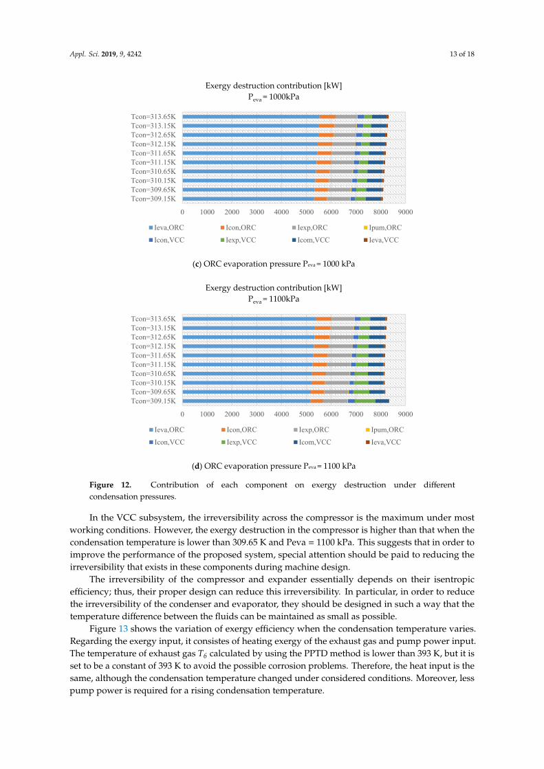
Figure 12. Contribution of each component on exergy destruction under different condensation pressures.
Figure 13 shows the variation of exergy efficiency when the condensation temperature varies. Regarding the exergy input, it consistes of heating exergy of the exhaust gas and pump power input. The temperature of exhaust gas T6 calculated by using the PPTD method is lower than 393 K, but it is set to be a constant of 393 K to avoid the possible corrosion problems. Therefore, the heat input is the same, although the condensation temperature changed under considered conditions. Moreover, less pump power is required for a rising condensation temperature.
Regarding the useful exergy output, the cooling exergy is found to be reduced at its higher VCC evaporation temperature, explaining the reason as to why the exergy efficiency declines as the condensation temperature increases, except at Peva = 1100 kPa.
For Peva = 1100 kPa, the exergy destruction of the expansion valve decreases sharply when the condensation temperature increases from 309.2 to 309.7 K (see Figure 12d), and a valley value at 309.7 K appeared, explaining why there is the maximum exergy efficiency under this condition.
0 1000 2000 3000 4000 5000 6000 7000 8000 9000
Tcon=309.15KTcon=309.65KTcon=310.15KTcon=310.65KTcon=311.15KTcon=311.65KTcon=312.15KTcon=312.65KTcon=313.15KTcon=313.65K
Exergy destruction contribution [kW] Peva = 1000kPa
Ieva,ORC Icon,ORC Iexp,ORC Ipum,ORCIcon,VCC Iexp,VCC Icom,VCC Ieva,VCC
0 1000 2000 3000 4000 5000 6000 7000 8000 9000
Tcon=309.15KTcon=309.65KTcon=310.15KTcon=310.65KTcon=311.15KTcon=311.65KTcon=312.15KTcon=312.65KTcon=313.15KTcon=313.65K
Exergy destruction contribution [kW] Peva = 1100kPa
Ieva,ORC Icon,ORC Iexp,ORC Ipum,ORCIcon,VCC Iexp,VCC Icom,VCC Ieva,VCC
Figure 12. Contribution of each component on exergy destruction under differentcondensation pressures.
In the VCC subsystem, the irreversibility across the compressor is the maximum under mostworking conditions. However, the exergy destruction in the compressor is higher than that when thecondensation temperature is lower than 309.65 K and Peva = 1100 kPa. This suggests that in order toimprove the performance of the proposed system, special attention should be paid to reducing theirreversibility that exists in these components during machine design.
The irreversibility of the compressor and expander essentially depends on their isentropicefficiency; thus, their proper design can reduce this irreversibility. In particular, in order to reducethe irreversibility of the condenser and evaporator, they should be designed in such a way that thetemperature difference between the fluids can be maintained as small as possible.
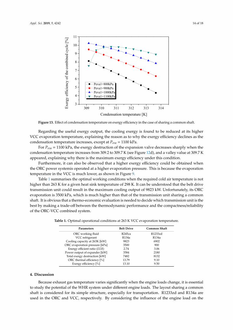
Figure 13 shows the variation of exergy efficiency when the condensation temperature varies.Regarding the exergy input, it consistes of heating exergy of the exhaust gas and pump power input.The temperature of exhaust gas T6 calculated by using the PPTD method is lower than 393 K, but it isset to be a constant of 393 K to avoid the possible corrosion problems. Therefore, the heat input is thesame, although the condensation temperature changed under considered conditions. Moreover, lesspump power is required for a rising condensation temperature.
Appl. Sci. 2019, 9, 4242 14 of 18
Appl. Sci. 2019, 9, x FOR PEER REVIEW 16 of 20
Furthermore, it can also be observed that a higher exergy efficiency could be obtained when the ORC power systemis operated at a higher evaporation pressure. This is because the evaporation temperature in the VCC is much lower, as shown in Figure 9.
309 310 311 312 313 3143
4
5
6
7
8
9
10
11
Exer
gy e
ffici
ency
of t
he c
ombi
ned
cycl
e [%
]
Condensation temperature [K]
Peva1=800kPa Peva1=900kPa Peva1=1000kPa Peva1=1100kPa
Figure 13. Effect of condensation temperature on exergy efficiency in the case of sharing a common shaft.
Table 1 summarises the optimal working conditions when the required cold air temperature is not higher than 263 K for a given heat sink temperature of 298 K. It can be understood that the belt drive transmission unit could result in the maximum cooling output of 9823 kW. Unfortunately, its ORC evaporation is 3500 kPa, which is much higher than that of the transmission unit sharing a common shaft. It is obvious that a thermo-economic evaluation is needed to decide which transmission unit is the best by making a trade-off between the thermodynamic performance and the compactness/reliability of the ORC-VCC combined system.
Table 1. Optimal operational conditions at 263 K VCC evaporation temperature.
Parameters Belt Drive Common Shaft ORC working fluid R245ca R1233zd
VCC refrigerant R134a R134a Cooling capacity at 263K [kW] 9823 6902
ORC evaporation pressure [kPa] 3500 900 Energy efficient ratio (EER) 2.74 3.06
Power output of expander [kW] 3584 2180 Total exergy destruction [kW] 7482 8132
ORC thermal efficiency [%] 13.79 9.10 Exergy efficiency [%] 13.10 9.50
4. Discussion
Because exhaust gas temperature varies significantly when the engine loads change, it is essential to study the potential of the WHR system under different engine loads. The layout sharing a common shaft is considered for its simple structure, especially for transportation. R1233zd and R134a are used in the ORC and VCC, respectively. By considering the influence of the engine load on the operation of the ORC-VCC WHR system, an evaluation of the performance was conducted in this
Figure 13. Effect of condensation temperature on exergy efficiency in the case of sharing a common shaft.
Regarding the useful exergy output, the cooling exergy is found to be reduced at its higherVCC evaporation temperature, explaining the reason as to why the exergy efficiency declines as thecondensation temperature increases, except at Peva = 1100 kPa.
For Peva = 1100 kPa, the exergy destruction of the expansion valve decreases sharply when thecondensation temperature increases from 309.2 to 309.7 K (see Figure 12d), and a valley value at 309.7 Kappeared, explaining why there is the maximum exergy efficiency under this condition.
Furthermore, it can also be observed that a higher exergy efficiency could be obtained whenthe ORC power systemis operated at a higher evaporation pressure. This is because the evaporationtemperature in the VCC is much lower, as shown in Figure 9.
Table 1 summarises the optimal working conditions when the required cold air temperature is nothigher than 263 K for a given heat sink temperature of 298 K. It can be understood that the belt drivetransmission unit could result in the maximum cooling output of 9823 kW. Unfortunately, its ORCevaporation is 3500 kPa, which is much higher than that of the transmission unit sharing a commonshaft. It is obvious that a thermo-economic evaluation is needed to decide which transmission unit is thebest by making a trade-off between the thermodynamic performance and the compactness/reliabilityof the ORC-VCC combined system.
Table 1. Optimal operational conditions at 263 K VCC evaporation temperature.
Parameters Belt Drive Common Shaft
ORC working fluid R245ca R1233zdVCC refrigerant R134a R134a
Cooling capacity at 263K [kW] 9823 6902ORC evaporation pressure [kPa] 3500 900
Energy efficient ratio (EER) 2.74 3.06Power output of expander [kW] 3584 2180Total exergy destruction [kW] 7482 8132
ORC thermal efficiency [%] 13.79 9.10Exergy efficiency [%] 13.10 9.50
4. Discussion
Because exhaust gas temperature varies significantly when the engine loads change, it is essentialto study the potential of the WHR system under different engine loads. The layout sharing a commonshaft is considered for its simple structure, especially for transportation. R1233zd and R134a areused in the ORC and VCC, respectively. By considering the influence of the engine load on the
Appl. Sci. 2019, 9, 4242 15 of 18
operation of the ORC-VCC WHR system, an evaluation of the performance was conducted in thispaper with respect to the cooling output at the same temperature. The following analysis is based onthe flowing operating conditions. The ambient temperature and the sea water (heat sink) are both298 K, the refrigeration temperature T15 is 263 K, which is low enough for both air conditioning andfood preservation. The condensation ranges from 309 to 313 K, and the low temperature is limited bythe heat sink temperature. The ORC evaporation pressure is the optimal pressure of 900 kPa listed inTable 1.
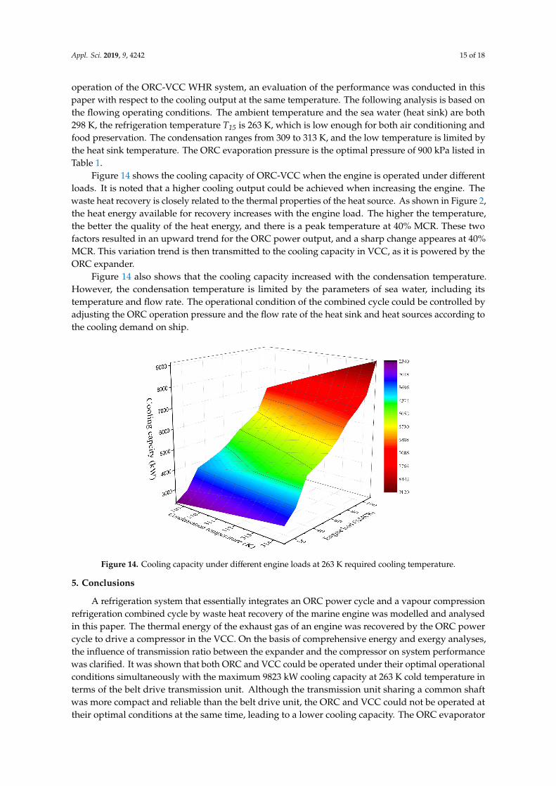
Figure 14 shows the cooling capacity of ORC-VCC when the engine is operated under differentloads. It is noted that a higher cooling output could be achieved when increasing the engine. Thewaste heat recovery is closely related to the thermal properties of the heat source. As shown in Figure 2,the heat energy available for recovery increases with the engine load. The higher the temperature,the better the quality of the heat energy, and there is a peak temperature at 40% MCR. These twofactors resulted in an upward trend for the ORC power output, and a sharp change appeares at 40%MCR. This variation trend is then transmitted to the cooling capacity in VCC, as it is powered by theORC expander.
Figure 14 also shows that the cooling capacity increased with the condensation temperature.However, the condensation temperature is limited by the parameters of sea water, including itstemperature and flow rate. The operational condition of the combined cycle could be controlled byadjusting the ORC operation pressure and the flow rate of the heat sink and heat sources according tothe cooling demand on ship.
Appl. Sci. 2019, 9, x FOR PEER REVIEW 17 of 20
paper with respect to the cooling output at the same temperature. The following analysis is based on the flowing operating conditions. The ambient temperature and the sea water (heat sink) are both 298 K, the refrigeration temperature T15 is 263 K, which is low enough for both air conditioning and food preservation. The condensation ranges from 309 to 313 K, and the low temperature is limited by the heat sink temperature. The ORC evaporation pressure is the optimal pressure of 900 kPa listed in Table 1.
Figure 14 shows the cooling capacity of ORC-VCC when the engine is operated under different loads. It is noted that a higher cooling output could be achieved when increasing the engine. The waste heat recovery is closely related to the thermal properties of the heat source. As shown in Figure 2, the heat energy available for recovery increases with the engine load. The higher the temperature, the better the quality of the heat energy, and there is a peak temperature at 40% MCR. These two factors resulted in an upward trend for the ORC power output, and a sharp change appeares at 40% MCR. This variation trend is then transmitted to the cooling capacity in VCC, as it is powered by the ORC expander.
Figure 14 also shows that the cooling capacity increased with the condensation temperature. However, the condensation temperature is limited by the parameters of sea water, including its temperature and flow rate. The operational condition of the combined cycle could be controlled by adjusting the ORC operation pressure and the flow rate of the heat sink and heat sources according to the cooling demand on ship.
Figure 14. Cooling capacity under different engine loads at 263 K required cooling temperature.
5. Conclusions
A refrigeration system that essentially integrates an ORC power cycle and a vapour compression refrigeration combined cycle by waste heat recovery of the marine engine was modelled and analysed in this paper. The thermal energy of the exhaust gas of an engine was recovered by the ORC power cycle to drive a compressor in the VCC. On the basis of comprehensive energy and exergy analyses, the influence of transmission ratio between the expander and the compressor on system performance was clarified. It was shown that both ORC and VCC could be operated under their optimal operational conditions simultaneously with the maximum 9823 kW cooling capacity at 263 K cold temperature in terms of the belt drive transmission unit. Although the transmission unit sharing a common shaft was more compact and reliable than the belt drive unit, the ORC and VCC could not be operated at their optimal conditions at the same time, leading to a lower cooling capacity. The
Figure 14. Cooling capacity under different engine loads at 263 K required cooling temperature.
5. Conclusions
A refrigeration system that essentially integrates an ORC power cycle and a vapour compressionrefrigeration combined cycle by waste heat recovery of the marine engine was modelled and analysedin this paper. The thermal energy of the exhaust gas of an engine was recovered by the ORC powercycle to drive a compressor in the VCC. On the basis of comprehensive energy and exergy analyses,the influence of transmission ratio between the expander and the compressor on system performancewas clarified. It was shown that both ORC and VCC could be operated under their optimal operationalconditions simultaneously with the maximum 9823 kW cooling capacity at 263 K cold temperature interms of the belt drive transmission unit. Although the transmission unit sharing a common shaftwas more compact and reliable than the belt drive unit, the ORC and VCC could not be operated attheir optimal conditions at the same time, leading to a lower cooling capacity. The ORC evaporator
Appl. Sci. 2019, 9, 4242 16 of 18
contributed the most significant part of the exergy loss in the ORC-VCC combined system because ofits significant irreversibility associated with heat transfer across large temperature differences. Thecooling capacity showed an upward trend with increasing engine load. A sharp change appeared at40% MCR because of the high temperature in the exhaust gas. The thermo-economic evaluation of thesystem and corresponding experimental validations will be conducted in the future work.
Author Contributions: Y.L. built the model of the combined ORC-VCC cycle, analysed the results and write thewhole papers. Z.Y. provided the supervision of the paper writing and revision. W.L. participated in the paperrevision. All the authors read and approve the manuscript.
Funding: Engineering and Physical Sciences Research Council: EP/N020472/1, Engineering and Physical SciencesResearch Council: EP/N005228/1, Engineering and Physical Sciences Research Council: EP/R003122/1, Engineeringand Physical Sciences Research Council: EP/P028829/1
Acknowledgments: This research was funded by Engineering and Physical Sciences Research Council(EP/N020472/1, EP/N005228/1, EP/R003122/1, and EP/P028829/1) in the United Kingdom. We gratefullyacknowledge the assistance of Hongyang Li in proofreading.
Conflicts of Interest: The authors declare no conflict of interest.
Abbreviations
NomenclatureIC Internal combustionECCS Electricity-cooling combined systemMCR Contract maximum continuous ratingCOP Coefficient of performanceEER Energy efficiency ratioHFO Heavy fuel oilPPTD Pinch point temperature differenceORC Organic Rankine cycleSRC Steam Rankine cycleVCC Vapour compression cycleWHR Waste heat recoverySymbolsE Exergy (kW)h Specific enthalpy (kJ/kg)I Exergy destructionm Mass flow rate (kg/s)Q Heat (kW)T Temperature (K)W Power (kW)η EfficiencySubscriptcond Condenserexp Expanderexh Exhaust gascom Compressoreva Evaporatorex Exergyin Inputis Isentropic processf1 Working fluid in ORCf2 Working fluid in VCCpump Fluid pumpout Outputw Water0 Reference environment
Appl. Sci. 2019, 9, 4242 17 of 18
References
1. UNEP. Green Economy in a Blue World; Synthesis Report; The WordFish Center Working Papers: Geneva,Switzerland, 2012.
2. Tsitsilonis, K.M.; Theotokatos, G. A novel systematic methodology for ship propulsion engines energymanagement. J. Clean. Prod. 2018, 204, 212–236. [CrossRef]
3. Shu, G.; Liang, Y.; Wei, H.; Tian, H.; Zhao, J.; Liu, L. A review of waste heat recovery on two-stroke IC engineaboard ships. Renew. Sustain. Energy Rev. 2013, 19, 385–401. [CrossRef]
4. Bidini, G.; di Maria, F.; Generosi, M. Micro-cogeneration system for a small passenger vessel operating in anature reserve. Appl. Therm. Eng. 2005, 25, 851–865. [CrossRef]
5. Tien, W.K.; Yeh, R.H.; Hong, J.M. Theoretical analysis of cogeneration system for ships. Energy Convers.Manag. 2007, 48, 1965–1974. [CrossRef]
6. Rigby, G.R.; Hallegraeff, G.M.; Sutton, C. Novel ballast water heating technique offers cost-effective treatmentto reduce the risk of global transport of harmful marine organisms. Mar. Ecol. Prog. Ser. 1999, 191, 289–293.[CrossRef]
7. Theotokatos, G.; Livanos, G. Exhaust gas waste heat recovery in marine propulsion plants. In SustainableMaritime Transportation and Exploitation of Sea Resources; CRC Press: Boca Raton, FL, USA, 2001; pp. 663–671.
8. Theotokatos, G.; Livanos, G. Techno-Economical analysis of single pressure exhaust gas waste heat recoverysystems in marine propulsion plants. Proc. Inst. Mech. Eng. Part M J. Eng. Marit. Environ. 2013, 227, 83–97.[CrossRef]
9. Altosole, M.; Laviola, M.; Trucco, A.; Sabattini, A. Waste heat recovery systems from marine diesel engines:Comparison between new design and retrofitting solutions. In Maritime Technology and Engineering; CRCPress: Boca Raton, FL, USA, 2014; pp. 735–742.
10. Benvenuto, G.; Trucco, A.; Campora, U. Optimization of waste heat recovery from the exhaust gas of marinediesel engines. Proc. Inst. Mech. Eng. Part M J. Eng. Marit. Environ. 2014, 230, 83–94. [CrossRef]
11. Hung, T.C. Waste heat recovery of organic Rankine cycle using dry fluids. Energy Convers. Manag. 2001, 42,539–553. [CrossRef]
12. Singh, D.V.; Pedersen, E. A review of waste heat recovery technologies for maritime applications. EnergyConvers. Manag. 2016, 111, 315–328. [CrossRef]
13. Baldi, F.; Gabrielii, C. A feasibility analysis of waste heat recovery systems for marine applications. Energy2015, 80, 654–665. [CrossRef]
14. Andreasen, J.G.; Meroni, A.; Haglind, F. A comparison of organic and steam Rankine cycle power systemsfor waste heat recovery on large ships. Energies 2017, 10, 547. [CrossRef]
15. Liang, Y.; Shu, G.; Tian, H.; Liang, X.; Wei, H.; Liu, L. Analysis of an electricity–cooling cogeneration systembased on RC–ARS combined cycle aboard ship. Energy Convers. Manag. 2013, 76, 1053–1060. [CrossRef]
16. Liang, Y.; Shu, G.; Tian, H.; Wei, H.; Liang, X.; Liu, L.; Wang, X. Theoretical analysis of a novelelectricity–cooling cogeneration system (ECCS) based on cascade use of waste heat of marine engine.Energy Convers. Manag. 2014, 85, 888–894. [CrossRef]
17. Liang, Y.; Shu, G.; Tian, H.; Sun, Z. Investigation of a cascade waste heat recovery system based on couplingof steam Rankine cycle and NH3-H2O absorption refrigeration cycle. Energy Convers. Manag. 2018, 166,697–703. [CrossRef]
18. Zhang, N.; Lior, N. Methodology for thermal design of novel combined refrigeration/power binary fluidsystems. Int. J. Refrig. 2007, 30, 1072–1085. [CrossRef]
19. Pouraghaie, M.; Atashkari, K.; Besarati, S.M.; Nariman-Zadeh, N. Thermodynamic performance optimizationof a combined power/cooling cycle. Energy Convers. Manag. 2010, 51, 204–211. [CrossRef]
20. Demirkaya, G.; Vasquez, P.R.; Goswami, D.Y.; Stefanakos, E.; Rahman, M.M. Analysis of a combined powerand cooling cycle for low-grade heat sources. Int. J. Energy Res. 2011, 35, 1145–1157. [CrossRef]
21. Prigmore, D.; Barber, R. Cooling with the Sun’s heat design consideration and test data for a Rankine cycleprototype. Sol. Energy 1975, 17, 185–192. [CrossRef]
22. Wang, H.; Peterson, R.; Harada, K.; Miller, E.; Ingram-Goble, R.; Fisher, L.; Yih, J.; Ward, C. Performance of acombined organic Rankine cycle and vapor compression cycle for heat activated cooling. Energy 2011, 36,447–458. [CrossRef]
Appl. Sci. 2019, 9, 4242 18 of 18
23. Wang, H.; Peterson, R.; Herron, T. Design study of configurations on system COP for a combined ORC(organic Rankine cycle) and VCC (vapor compression cycle). Energy 2011, 36, 4809–4820. [CrossRef]
24. Wali, E. Working fluids for solar, Rankine-cycle cooling systems. Energy 1980, 5, 631–639. [CrossRef]25. Wali, E. Optimum working fluids for solar powered Rankine cycle cooling of buildings. Sol. Energy 1980, 25,
235–241. [CrossRef]26. Aphornratana, S.; Sriveerakul, T. Analysis of a combined Rankine-vapor-compression refrigeration cycle.
Energy Convers. Manag. 2010, 51, 2557–2564. [CrossRef]27. Bu, X.; Wang, L.; Li, H. Performance analysis and working fluid selection for geothermal energy-powered
organic Rankine-vapor compression air conditioning. Geotherm. Energy 2013, 1, 2. [CrossRef]28. Bu, X.B.; Li, H.S.; Wang, L.B. Performance analysis and working fluids selection of solar powered organic
Rankine-vapor compression ice maker. Sol. Energy 2013, 95, 271–278. [CrossRef]29. Bu, X.; Wang, L.; Li, H. Working fluids selection for fishing boats waste heat powered organic Rankine-vapor
compression ice maker. Heat Mass Transf. 2014, 50, 1479–1485. [CrossRef]30. Biancardi, F.R.; Sitler, J.W.; Melikian, G. Development and test of solar Rankine cycle heating and cooling
systems. Int. J. Refrig. 1982, 5, 351–360. [CrossRef]31. Demierre, J.; Henchoz, S.; Favrat, D. Prototype of a thermally driven heat pump based on integrated Organic
Rankine Cycles (ORC). Energy 2012, 41, 10–17. [CrossRef]32. Demierre, J.; Favrat, D.; Schiffmann, J.; Wegele, J. Experimental investigation of a Thermally Driven Heat
Pump based on a double Organic Rankine Cycle and an oil-free Compressor-Turbine Unit. Int. J. Refrig.2014, 44, 91–100. [CrossRef]
33. Wan, X.; Cai, L.; Yan, J.; Ma, X.; Chen, T.; Zhang, X. Power management strategy for a parallel hybrid-powergas engine heat pump system. Appl. Therm. Eng. 2017, 110, 234–243. [CrossRef]
34. Shang, S.; Li, X.; Wu, W.; Wang, B.; Shi, W. Energy-saving analysis of a hybrid power-driven heat pumpsystem. Appl. Therm. Eng. 2017, 123, 1050–1059. [CrossRef]
35. Liang, Y.; Al-Tameemi, M.; Yu, Z. Investigation of a gas-fuelled water heater based on combined power andheat pump cycles. Appl. Energy 2018, 212, 1476–1488. [CrossRef]
36. Liang, Y.; Bian, X.; Qian, W.; Pan, M.; Ban, Z.; Yu, Z. Theoretical analysis of a regenerative supercriticalcarbon dioxide Brayton cycle/organic Rankine cycle dual loop for waste heat recovery of a diesel/natural gasdual-fuel engine. Energy Convers. Manag. 2019, 197, 111845. [CrossRef]
37. Prevention of Air Pollution from Ships-Updated 2000 Study on Greenhouse Gas Emissions from Ships Phase 1 Report;MEPC 58/INF. 6; International Maritime Organization (IMO): London, UK, 2008.
38. Technical File for Hyundai-Man B&W 12K98MC-C Mk6; Hyundai Heavy Industries Co., Ltd.: Ulsan, Korea,2006.
39. Poling, B.E.; Prausnitz, J.M.; O’Connell, J.P. The Properties of Gases and Liquids; McGraw-Hill: New York, NY,USA, 2001; Volume 5.
40. Shu, G.; Liu, L.; Tian, H.; Wei, H.; Liang, Y. Analysis of regenerative dual-loop organic Rankine cycles(DORCs) used in engine waste heat recovery. Energy Convers. Manag. 2013, 76, 234–243. [CrossRef]
41. Li, X.; Song, J.; Yu, G.; Liang, Y.; Tian, H.; Shu, G.; Markides, C.N. Organic Rankine cycle systems for enginewaste-heat recovery: Heat exchanger design in space-constrained applications. Energy Convers. Manag. 2019,199, 111968. [CrossRef]
© 2019 by the authors. Licensee MDPI, Basel, Switzerland. This article is an open accessarticle distributed under the terms and conditions of the Creative Commons Attribution(CC BY) license (http://creativecommons.org/licenses/by/4.0/).