Embed Size (px)
Citation preview
Paper ID #7298
A Versatile Guide and Rubric to Scaffold and Assess Engineering DesignProjects
Dr. Robert L. Nagel, James Madison University
Dr. Robert Nagel is an Assistant Professor in the Department of Engineering at James Madison University.Dr. Nagel joined the James Madison University after completing his Ph.D. in mechanical engineering atOregon State University. He has a B.S. from Tri-State University (now Trine University) and a M.S. fromthe University of Missouri-Rolla (now Missouri University of Science and Technology), both in mechani-cal engineering. Dr. Nagel has performed research with the United States Army Chemical Corps, GeneralMotors Research and Development Center, and the United States Air Force Academy. His research in-terests are in the area of conceptual design and engineering design education. Specifically, Dr. Nagel’sresearch activities include understanding customer needs, the use functional and process modeling tounderstand design problems, design for sustainability, and design for accessibility.
Dr. Olga Pierrakos, James Madison University
OLGA PIERRAKOS is an associate professor and founding faculty member of the James Madison Uni-versity Department of Engineering, which graduated its inaugural class in May 2012. At JMU, Dr. Pier-rakos is the Director of the Center for Innovation in Engineering Education (CIEE) and Director of theAdvanced Thermal Fluids Laboratory. Her interests in engineering education research center aroundrecruitment and retention, engineer identity, engineering design instruction and methodology, learningthrough service, problem based learning methodologies, assessment of student learning, as well as com-plex problem solving. Her other research interests lie in cardiovascular fluid mechanics, sustainability, andK-12 engineering outreach. Dr. Pierrakos is a 2009 NSF CAREER Awardee. Dr. Pierrakos holds a B.S.in Engineering Science and Mechanics, an M.S. in Engineering Mechanics, and a Ph.D. in BiomedicalEngineering from Virginia Tech.
Dr. Jacquelyn Kay Nagel, James Madison University
Dr. Jacquelyn K. Nagel is an Assistant Professor in the Department of Engineering at James MadisonUniversity. Prior to JMU she worked as engineering contractor at Mission Critical Technologies workingon the DARPA funded Meta-II Project. Dr. Nagel has seven years of diversified engineering design ex-perience, both in academia and industry, and has experienced engineering design in a range of contexts,including: product design, biomimetic design, electrical and control system design, manufacturing systemdesign and design for the factory floor. She earned her Ph.D. in Mechanical Engineering from OregonState University, and her M.S. and B.S. in Manufacturing Engineering and Electrical Engineering, respec-tively, from the Missouri University of Science & Technology (formerly University of Missouri-Rolla).Dr. Nagel’s research interests include biomimicry, sensors, sustainable energy, engineering design, andmanufacturing.
c©American Society for Engineering Education, 2013
A Versatile Guide and Rubric to Scaffold and Assess Engineering Design Projects
Abstract
This paper presents a versatile guide and rubric for assessment of engineering design projects throughout an engineering curriculum. The guide is comprised of three key parts: (1) a typical design process-to-semester mapping for capstone projects, (2) a design process rubric applicable to engineering design projects in the curriculum, and (3) a mapping between the design process and engineering design tools taught within the curriculum. The design process guide is presented as a tool which can be used to guide students through directed exploration of the design process during a first design class as well as to scaffold students’ undirected design process exploration. Implementation of the guide during the engineering design sequence will be discussed as well as the lessons learned after applying the guide to senior and junior projects as a grading rubric, feedback mechanism, and as an in-class guide for student reflection on a project’s process.
Introduction
The relatively new James Madison University (JMU) engineering program has been designed to train the Engineer of 20201,2. The program was developed from the ground up to not be an engineering discipline-specific program, but to provide students training with an emphasis on engineering design, systems thinking, and sustainability while also providing a strong foundation in engineering science3. The vision of the program is to produce cross-disciplinary engineer versatilists. At the heart of the program is the six-course engineering design sequence which provides instruction on design theory (thinking, process, methods, tools, etc.), sustainability, ethics, team management, and technical communication (both oral and written), while incorporating elements of engineering science and analysis4,5. Students apply design instruction in the context of two projects during the six-course sequence—a cornerstone project spanning the fall and spring semesters of the sophomore year, and a capstone project spanning the junior and senior academic years. As the inaugural class neared their graduation and the program grew, it became clear that an engineering design process rubric that could be used from the first semester of the sophomore year through the final semester of senior year would be needed to ensure consistency across projects. The diversity of projects has varied widely with projects spanning a variety of traditional engineering disciplines. Example projects include electric motorcycles and scooters, composting reactors, fire-fighting robots, biology-inspired drag reduction systems, a health clinic for sub-Saharan Africa, and a distributable hearing test system. This project diversity resulted in students being exposed to a variety of different manifestations of the design process. In other words, the design process (i.e. linearity of steps followed, methods and techniques used, duration of each design stage, etc.) varied across projects because the design process was customized to each project and each team. During the first two runs of the capstone design experience, this diversity of design processes caused confusion among students and faculty advisors. The outcome for getting all these individuals on the same page was the design of a versatile guide and rubric for assessment of engineering design projects.
The design faculty led the development and piloting of this versatile design process guide. Three fundamental requirements were identified for this design process guide to include: (1) a typical design process-to-semester mapping for capstone projects, (2) a design process rubric applicable to all engineering design projects across the JMU curriculum, and (3) a mapping between the design process and engineering design tools taught within the curriculum. With design as a core element of the program, the guide was designed such that it can be mapped to one-semester, two-semester, and four-semester student projects spanning an engineering curriculum. In this paper, the design process guide is presented as a tool which can be used to guide students through directed exploration of the design process during a first design class as well as scaffold students first undirected design process exploration. Implementation of the guide during the engineering design sequence will be discussed as well as the lessons learned after applying the guide to senior and junior projects as a grading rubric, feedback mechanism, and as an in-class guide for student reflection on a project’s process. Curriculum Overview
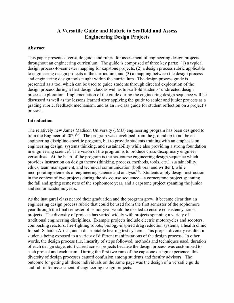
The curriculum of the JMU general engineering program, shown graphically in Figure 1, combines a campus-wide, liberal arts general educational core with courses in math, science, engineering design, engineering science, business, systems analysis, and sustainability6,7. Individual skills taught developmentally through the curriculum, beginning with the freshman year, are blended with engineering design theory and utilized in projects in the design sequence. The engineering design sequence is meant to be the core or spine of the engineering curriculum. During the engineering design courses, students not only learn engineering design tools and methods but also learn about creativity, sustainability, business, ethics, values, engineering science, math, and manufacturing. It is during this engineering design sequence where students are provided with a hands-on environment to apply the theory learned in other courses5.
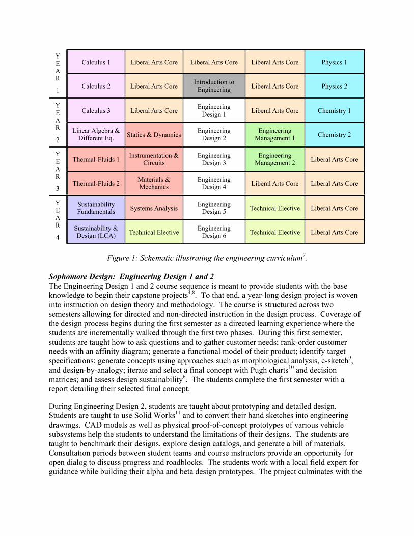
Figure 1: Schematic illustrating the engineering curriculum7. Sophomore Design: Engineering Design 1 and 2 The Engineering Design 1 and 2 course sequence is meant to provide students with the base knowledge to begin their capstone projects4,8. To that end, a year-long design project is woven into instruction on design theory and methodology. The course is structured across two semesters allowing for directed and non-directed instruction in the design process. Coverage of the design process begins during the first semester as a directed learning experience where the students are incrementally walked through the first two phases. During this first semester, students are taught how to ask questions and to gather customer needs; rank-order customer needs with an affinity diagram; generate a functional model of their product; identify target specifications; generate concepts using approaches such as morphological analysis, c-sketch9, and design-by-analogy; iterate and select a final concept with Pugh charts10 and decision matrices; and assess design sustainability6. The students complete the first semester with a report detailing their selected final concept.
During Engineering Design 2, students are taught about prototyping and detailed design. Students are taught to use Solid Works11 and to convert their hand sketches into engineering drawings. CAD models as well as physical proof-of-concept prototypes of various vehicle subsystems help the students to understand the limitations of their designs. The students are taught to benchmark their designs, explore design catalogs, and generate a bill of materials. Consultation periods between student teams and course instructors provide an opportunity for open dialog to discuss progress and roadblocks. The students work with a local field expert for guidance while building their alpha and beta design prototypes. The project culminates with the
YEAR
1
Calculus 1 Liberal Arts Core Liberal Arts Core Liberal Arts Core Physics 1YEAR
1Calculus 2 Liberal Arts Core Introduction to
Engineering Liberal Arts Core Physics 2
YEAR
2
Calculus 3 Liberal Arts Core Engineering Design 1 Liberal Arts Core Chemistry 1
YEAR
2Linear Algebra &
Different Eq. Statics & Dynamics Engineering Design 2
Engineering Management 1 Chemistry 2
YEAR
3
Thermal-Fluids 1 Instrumentation & Circuits
EngineeringDesign 3
Engineering Management 2 Liberal Arts Core
YEAR
3Thermal-Fluids 2 Materials &
MechanicsEngineering
Design 4 Liberal Arts Core Liberal Arts Core
YEAR
4
Sustainability Fundamentals Systems Analysis Engineering
Design 5 Technical Elective Liberal Arts CoreYEAR
4Sustainability & Design (LCA) Technical Elective Engineering
Design 6 Technical Elective Liberal Arts Core
students demonstrating their final product (a beta prototype) to the client as well as the University and the local community. Junior/Senior Design: Engineering Design 3 through 6 The Engineering Design 3 through 6 course sequence, respectively in the four semesters of the junior and senior years, is meant to provide students with advanced design instruction and also a capstone design experience. Topics covered through these courses includes: team code of conducts, technical communication, engineering ethics, professionalism, holistic design, psychology of design12, Theory of Inventive Problem Solving (TRIZ)13,14, Design for X, patents, marketing, Six Sigma and lean production, and Failure Mode and Effects Analysis (FMEA). The course is scheduled for three meetings times per week. One of those meetings is allocated for course instruction, a second is allocated for team/advisor meetings, and a third is allocated for team meetings. Considering that the allotted instructional time is one hour per week, the goal for these topics is to provide students a good exposure and some practice (either in the context of their capstone design project or a small PBL assignment such as a design challenge). During these full-class instruction periods, students consider and solve unstructured problems related to design and sustainability through case studies using visualization, writing, and personal reflection7. Students explore reciprocal effects of their potential decisions and the related ethical dilemmas inherent in environmental, social, and professional contexts. During the team/advisor meetings, teams focus on the technical aspects of their projects by meeting with their faculty advisors, who help to guide students through the engineering design process and technical details of the project. Also critical during these four-semester junior and senior design courses is a common and consistent schedule of key deadlines and deliverables (reports and presentations) for all capstone projects. Both capstone project advisors and design course instructors evaluate these deliverables and provide students feedback. For the capstone project experience, the capstone project advisors serve the role of technical advisors and provide their capstone teams with feedback in that capacity, whereas the course instructors serve the role of coordinators in setting common deliverables for all capstone teams, evaluating and providing all capstone teams feedback, and facilitating capstone teams and advisors when/if needed. In this four-semester capstone design experience, students apply the engineering design process and design tools and methods learned during the sophomore design sequence to their new projects. Projects are proposed by faculty members, and students bid into teams. Ultimately, each student is placed in either his or her first, second, or third choice project. The capstone project model is inspired by an industry design model that can be summarized in terms of five design reviews: systems requirement review, preliminary design review, critical design review, testing readiness review, and production readiness review. Overall, the first semester of the project is focused on problem formulation, research, and planning with some teams being able to start on the concept development design phase. At the core, for most capstone teams, the second semester focused on concept development and initial efforts towards prototyping and modeling, both of which continue into the third semester. Detailed designs are the culmination of efforts in the third semester and accompany testing and evaluation efforts. For several teams, the fourth semester continues to focus on testing and evaluation as well as redesign processes.
Development of the Design Process Guide The design process guide was designed to be a versatile tool applicable to a wide variety of student design projects seen throughout the curriculum whether they span one-semester, two, or four. The roots of the design process guide began as an effort to map design tools and design processes into a common framework that could be used to teach different models of engineering design within a single course15. In this work, Nagel et al. compared four different, yet complimentary, design methods: (1) Pahl and Beitz’s Systematic Approach to Design16, (2) Suh’s Axiomatic Design17,18, (3) Altshuller’s Theory of Inventive Problem Solving13,14, and (4) Ulwick’s Outcome-Driven Method19,20 to identify commonalities which could allow the four methods to be taught in a single semester by following a common process for engineering design. To arrive a common design process, the authors studied eleven published design processes in common engineering design texts21-31. Through this process, Nagel et al. deduced four broad activities of engineering design: Preliminary Design consists of exploration and learning; Conceptual Design consists of exploring the solution space; Embody Design consists of defining physical attributes; Detail Design consists of engineering analysis, manufacturing details, engineering drawings15. Additionally, in developing the guide, it was necessary to consider the student’s exposure to the design process throughout the curriculum. Students in the JMU engineering program are exposed to three different engineering design processes through their text books; these include: Engineering Design: A Project-Based Introduction by Dym and Little, Product Design and Development by Ulrich and Eppinger, and Engineering Design by Dieter and Schmidt. Descriptions of each exposure follows:
• During the sophomore design sequence, students learn from the Dym and Little text which follows a five-stage (problem definition, conceptual design, preliminary design, detailed design, and design communication) prescriptive model22. Each phase is comprised of a series of steps, and during the sophomore year, students follow each step of each phase in near-linear progression toward a final design.
• During the engineering management courses, students use Ulrich and Eppinger’s text and are exposed to the following six-phase generic product development process—Planning, Concept Development, System-Level Design, Detailed Design, Testing and Refinement, and Production Ramp-Up—and between each phase is a design review acting as a gate for transition into the next phase30.
• During the four course capstone design sequence, students use the Dieter and Schmidt
text which follows an eight-phase engineering design process—Define Problem, Gather Information, Concept Generation, Evaluate and Select Concept, Product Architecture, Configuration Design, Parametric Design, Detail Design32, which is also accompanied by a six phase product development process—planning, concept development, system-level design, detail design, testing and refinement, and production ramp-up—with its roots in the work of Asimow33 and represents a market driven perspective on the engineering design process.
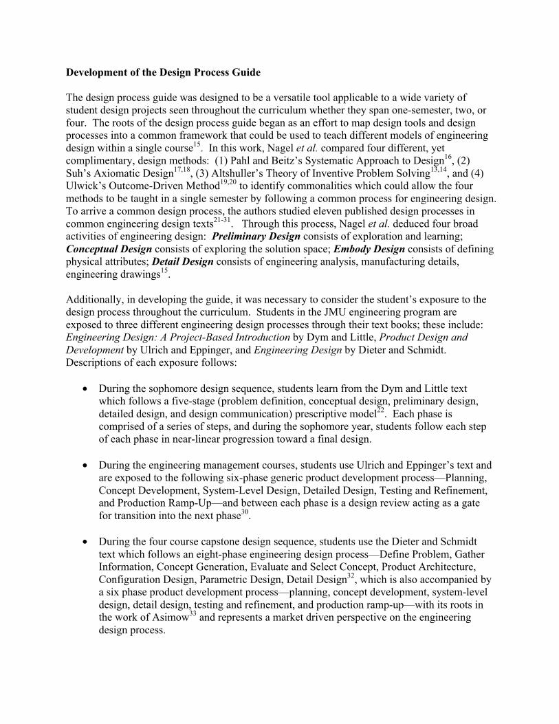
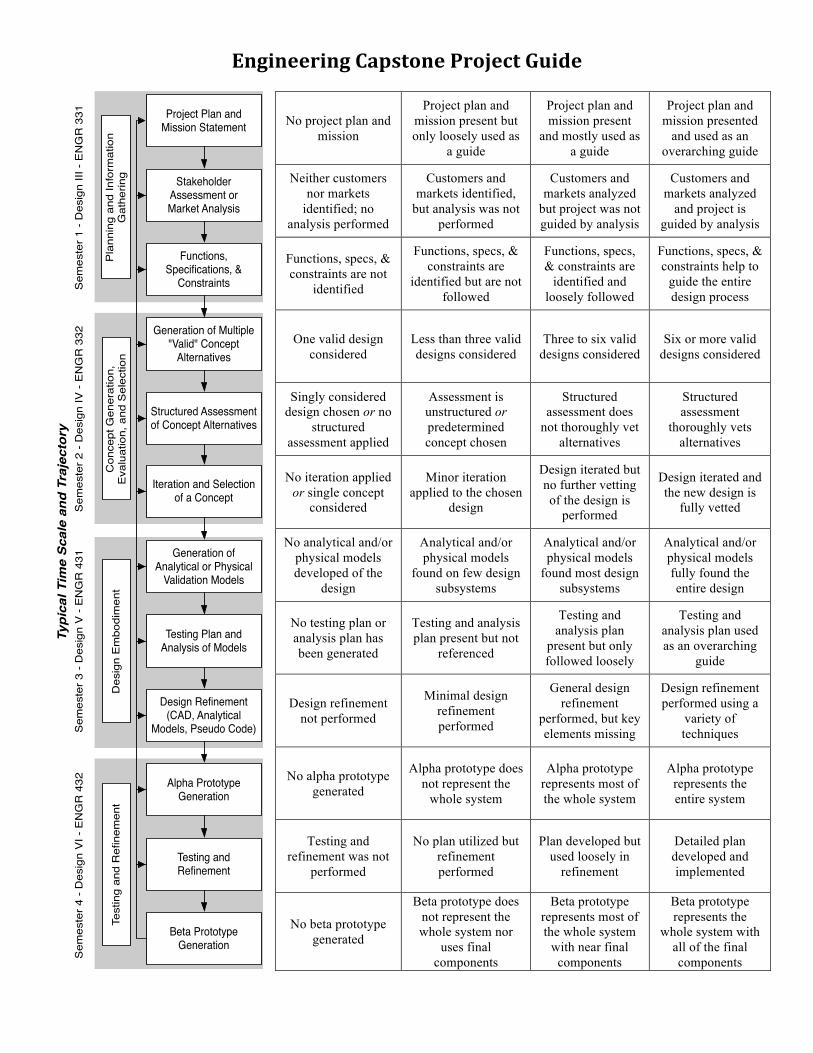
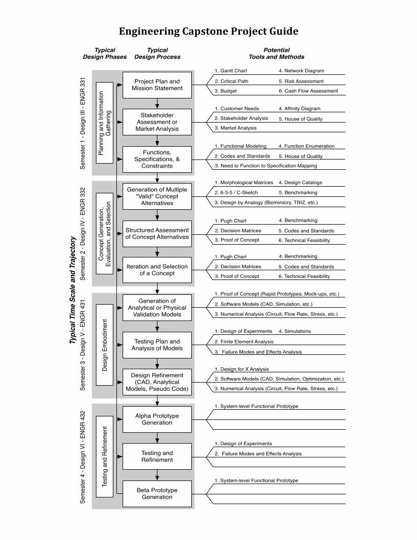
Consequently, while initial research efforts focused broadly, the design faculty wanted to ensure commonalities between the guide and the design processes published in the texts of Dym & Little22, Ulrich & Eppinger30, and Dieter & Schmidt21. Additionally, since the capstone design course sequence runs for four semesters, a desired design constraint of the design rubric was to incorporate just four phases rather than the five to eight in the design processes to which the students are exposed. This allows for coverage of two phases per semester during the two sophomore design courses and coverage of one phase per semester (see Figure 1 for reference on the structure of the design courses in the engineering curriculum) during the capstone design courses (junior and senior years). To arrive at the desired four-semester mapping, the authors returned to the original vision document5 of the capstone design sequence which called out four key phases: Planning and Conceptualization with a System Requirement Review (SRR) which focuses on addressing: problem identification and statement, project goals, literature review, market analysis, stakeholder analysis, analysis of available resources, feasibility study, and project management plan (budget, timeline, team member roles and responsibilities); Conceptualization, Modeling, and Prototyping with a Preliminary Design Review (PDR) which focuses on the evaluation of the conceptual design and planning of the project to ensure that teams are meeting the necessary requirements; Prototyping, Testing, and Evaluation with a Critical Design Review (CDR) which focuses on the evaluation of the detailed designs, prototyping models, and planning of the project to ensure the design implementation plan and a Testing Readiness Review (TRR) which focuses on the evaluation of testing preparations, readiness, and procedures; and Evaluation, Redesign, and Production with a Production Readiness Review (PRR) which focuses on the evaluation of the design to ensure that it is completely and accurately documented and ready for formal release to manufacturing. Marketability and commercialization of the design could also be evaluated. Design Process Guide In order to meet the constraints established by the engineering curriculum and maintain the original vision of the program while also basing the process on established literature, the authors initially went back to the four phases identified in the research of Nagel et al.15 which provided a semester-to-phase mapping. Then, to capture the additional phases that the students were familiar with, the names of each phase were adjusted to incorporate elements of the vision document as well as the design processes published in the student’s engineering design texts. The resultant four phases are: Planning and Information Gathering; Concept Generation, Evaluation, and Selection; Design Embodiment; and Testing and Refinement. Each phase was then divided into three additional distinct divisions that are likely to be completed during a phase. This design process represents the first portion of the engineering design guide. The specifics of each division of each phase follow and are provided as Figure 2:
• Planning and Information Gathering is divided into (1) project planning and mission statement, (2) stakeholder assessment and/or market analysis, and (3) functions, specifications, and constraints.
• Concept Generation, Evaluation, and Selection is divided into (1) generation of multiple ‘valid’ concept alternatives, (2) structured assessment of concept alternatives, and (3) iteration and selection of a concept.
• Design Embodiment is divided into (1) generation of analytical or physical validation
models, (2) testing plan and analysis of models, and (3) design refinement (CAD, analytical models, pseudo code, et cetera).
• Testing and Refinement is divided into (1) alpha prototype generation, (2) testing and
refinement, and (3) beta prototype generation.
Figure 2: Representation of the engineering design process used in the engineering design process guide.
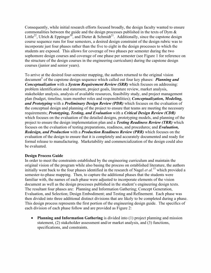
The second portion of the design process guide is the rubric which provides a breakdown from low to high quality completion for each of the three divisions comprising each phase of the design process outlined in the guide. This breakdown provides descriptions of quality at four levels ranging from absent to excellent for each step. Each is described textually so that a student and capstone faculty advisors can know what is expected of them as they work toward an excellent mark in each step of each phase of the process. An example portion correlating to the planning and information gathering phase of the design process is provided in Figure 3.
Figure 3: Engineering design rubric portion of the engineering design process guide.
Stakeholder Assessment or Market Analysis
Functions, Specifications, &
Constraints
Project Plan and Mission Statement
Plan
ning
and
Info
rmat
ion
Gat
herin
g
Generation of Multiple "Valid" Concept
Alternatives
Structured Assessment of Concept Alternatives
Iteration and Selection of a Concept
Con
cept
Gen
erat
ion,
Ev
alua
tion,
and
Sel
ectio
n
Testing Plan and Analysis of Models
Generation of Analytical or Physical
Validation Models
Design Refinement (CAD, Analytical
Models, Pseudo Code)
Des
ign
Embo
dim
ent
Testing Plan and Analysis of Models
Generation of Analytical or Physical
Validation Models
Design Refinement (CAD, Analytical
Models, Pseudo Code)
Des
ign
Embo
dim
ent
Typical Time Scale and TrajectorySemester 1- Design III - ENGR 331 Semester 2- Design IV - ENGR 332 Semester 3- Design V - ENGR 431 Semester 4- Design VI - ENGR 432
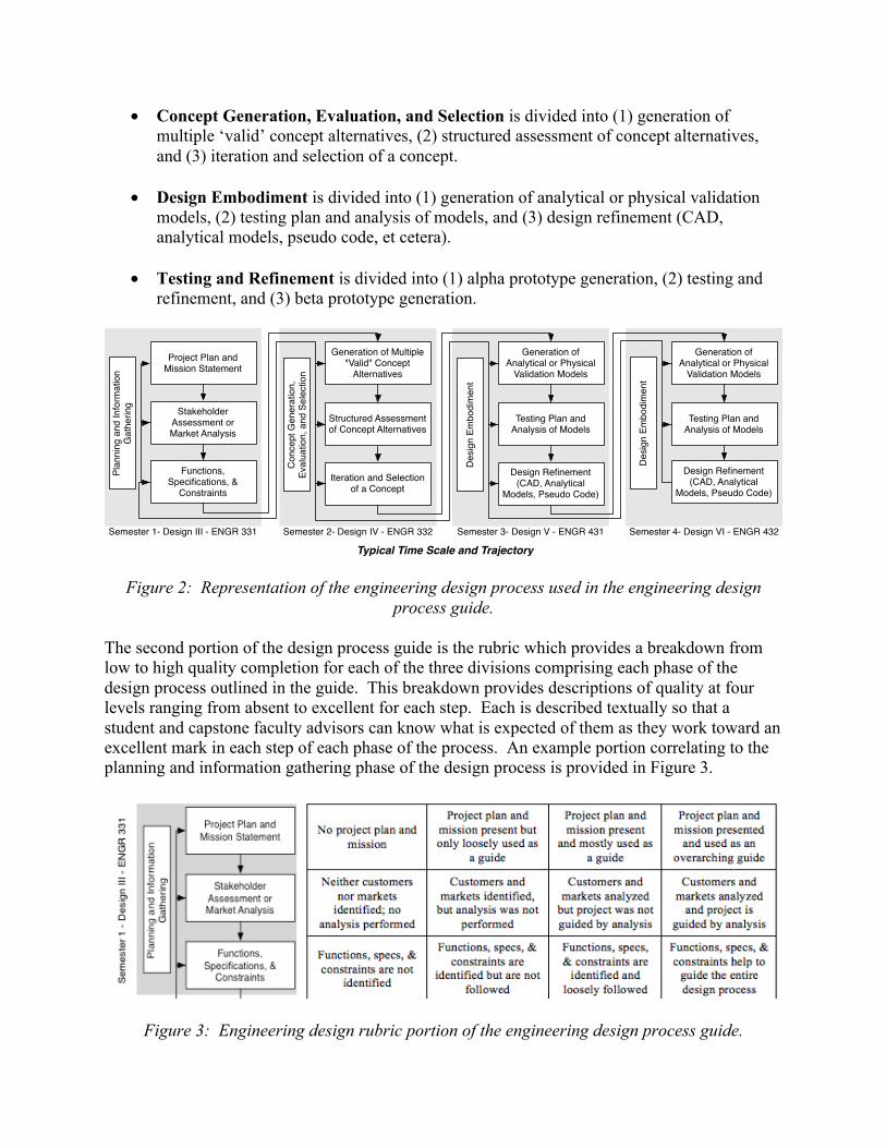
The third portion of the design process guide is a mapping between the design tools taught throughout the engineering curriculum and the design process presented on the rubric. Empirically it was noted that students in the program struggled to make the connections between their courses. Consequently, students were not integrating their knowledge, nor using the methods and tools learned throughout their courses in the engineering curriculum into the capstone experience. To help students through this process, the mapping was created as a scaffold that students could refer to at each step in each phase of the design process to help build the connections necessary to integrate knowledge. An example portion correlating to the planning and information gathering phase of the design process is provided in Figure 4.
Figure 4: Engineering design tools portion of the engineering design process guide.
The complete engineering design guide is provided as the last two pages of this paper. When provided to students and faculty, the guide is printed front to back on a single sheet of paper as to allow the user to read the process, understand what is required for an excellent in a particular phase of the design process, and then to review the tools and methods taught that can be used in each step of each phase of the design process. Implementation At present, the design process rubric is used implicitly in the sophomore design course and explicitly junior/senior design course sequence. The following two subsections describe how the rubric is used in each of these course sequences. Sophomore Design: Engineering Design 1 and 2 During the sophomore design course sequence, engineering students initially learn about the design process as a prescriptive approach to design completion, and as phases of the design process are completed, students reflect on their progression through the design process. The prescriptive introduction to the design process begins in Engineering Design 1 with a reading in Dym and Little’s Engineering Design; at the completion of the reading, students must compose their own definition of the engineering design process. Then at the completion of Engineering
Design 1 (following concept selection), the course instructor leads the class through a reflection/discussion of the design process followed during the term. Students map the tools and methods learned during the course onto the design process. During Engineering Design 2, students continue to follow a prescriptive engineering design process being taught appropriate engineering design tools at each step of the process. At the completion of Engineering Design 2, students again reflect on the engineering design process followed through the course. Students are asked to reflect on how each step was completed through the entire academic year. The final exam question for the entire course sequence consists of an essay question asking students to reflect on the process and describe their process for a new design challenge. It is important to note that the design process rubric is not explicitly used during Engineering Design 1 and 2, but the students are frequently exposed to its framework through course reflections. Junior/Senior Design: Engineering Design 3 through 6 During Engineering Design 3, students begin their two-year capstone experience. Students perform research on the faculty and student proposed projects and rank order their top four choices. Based on project and teammate preferences, students are placed in a capstone team of 4-5 students. The capstone goal of Engineering Design 3 is for student teams to develop a strong understanding of the project and foundational knowledge that will assist with meeting the project goals and deliverables. Students are provided the design process guide in the third week and during the last week in the semester during Engineering Design 3. Early in the semester the students are introduced to the design process guide to motivate the structure of the capstone course sequence as well as provide them a rubric for self assessing capstone project progress. Similar to the sophomore design courses, students reflect on the progress made on their course project at the completion of the Engineering Design 3 course. Emphasis, however, is put on progress through the design process rather than the process itself. Students are asked to reflect individually on the progress their team has made in the first semester of the project using the rubric portion of the design process guide. This is meant to capture the individual perceptions of how the project is progressing. Students then share their individual view on capstone project progress and discuss differences and similarities. Discovering there are multiple perceptions of progress instantly motivates discussion and assists teams with communicating. After reflecting on current progress, or lack there of, students are asked to work as a team to chart on the design process guide the progress they want to achieve by the end of Engineering Design 4, or the first year of capstone. Again, the design process guide is used as a means to encourage capstone teams to think about and discuss project progression, while simultaneously assess mastery of the design process. Use of the design process guide through the remaining courses in the engineering design sequence follows a process similar to the use during Engineering Design 3. At the beginning of Engineering Design 4 through 6 students reflect on their progress through the design process in prior semesters marking their attainment in each of the steps on the rubric portion of the guide. Through this reflection process, students are not expected to hit excellent attainment in all areas through linear progression. Students are taught that engineering design is a process by which an engineer is continually posing questions and seeking answers to those questions. Through asking
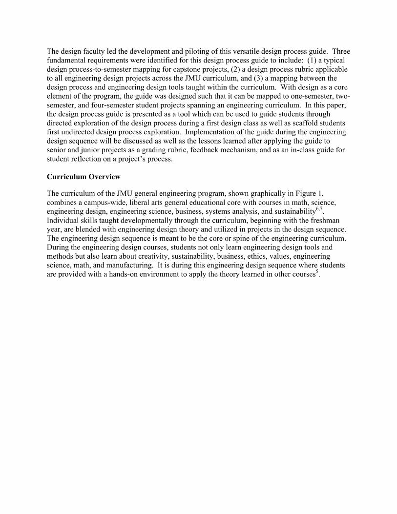
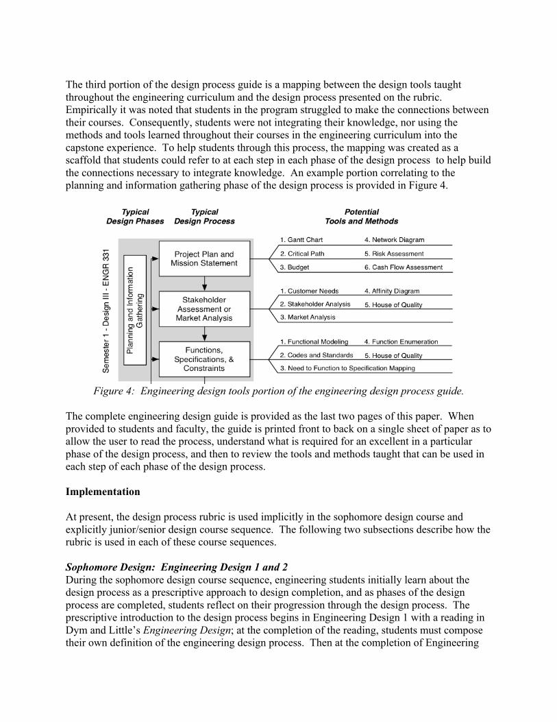
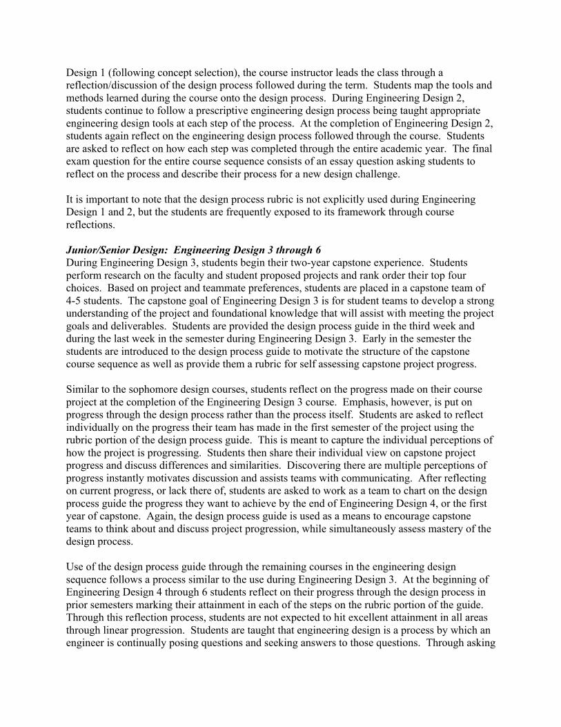
questions and seeking answers, student teams will move from the left hand side of the rubric to the right hand side of the rubric. Additionally, as students progress through the design courses, they will progress from the top of the page toward the bottom of the page. It is important for students to realize that they will not have excellent attainment in each step on first pass through a step. Students should understand that the process, while drawn and represented linearly, is not linear and is in fact iterative, collaborative, and unique to the capstone project and capstone team, and involves fact checking, updates, and dead-ends. And once an ‘expert’ designer, they may be able to reduce their wrong turns and dead-ends, but that these are a natural part of following a design process that results from learning new information as one seeks answers to questions posed. Example Capstone Implementations The following two subsections illustrate the use of the rubric portion of the guide during the engineering design course sequence. First, use of the rubric as a reflection tool at the completion of Engineering Design 3 is discussed. Second, two examples are provided of projects at the completion of Engineering Design 6. Students at the end of Engineering Design 6 use the rubric to reflect on their process as they prepare for their final oral exams and poster presentations. Capstone Team 1—Engineering Design 3 Completion Figure 5 provides a comparison between the perception of three students toward the engineering design process at the completion of their first semester in the capstone design sequence. Interestingly, the students agree with where they began in the design process at the start of the semester, and they are in agreement with their progress in the latter phases of the engineering design process. However, there is considerable disagreement between the students in how well stakeholder assessment and/or market analysis was fulfilled as well as how well function, specifications, and constraints were identified to inform their design process. It is at these disagreement points where there is fertile grounds for discussion between engineering students faculty advisors, and design instructors. These disagreements could also point to weaknesses in the student’s understanding of the design process and tools. For example, Student B had a distinctly different perspective on the team’s progress at the generation of multiple valid concept alternatives. These disagreements will hopefully lead to discussions where peers can learn from each other as they come to consensus on their actual progress through the semester.
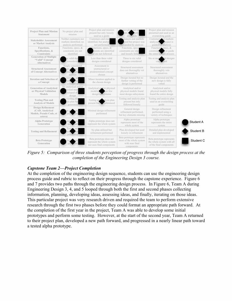
Figure 5: Comparison of three students perception of progress through the design process at the
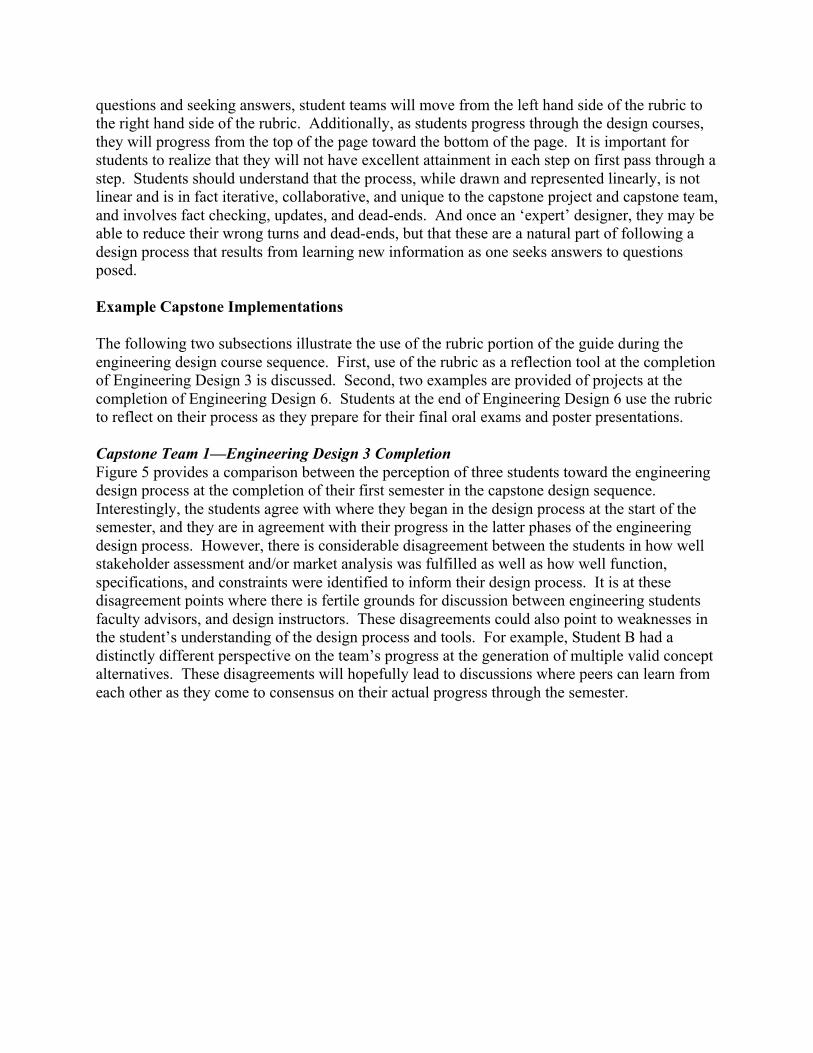
completion of the Engineering Design 3 course. Capstone Team 2—Project Completion At the completion of the engineering design sequence, students can use the engineering design process guide and rubric to reflect on their progress through the capstone experience. Figure 6 and 7 provides two paths through the engineering design process. In Figure 6, Team A during Engineering Design 3, 4, and 5 looped through both the first and second phases collecting information, planning, developing ideas, assessing ideas, and finally, iterating on those ideas. This particular project was very research driven and required the team to perform extensive research through the first two phases before they could format an appropriate path forward. At the completion of the first year in the project, Team A was able to develop some initial prototypes and perform some testing. However, at the start of the second year, Team A returned to their project plan, developed a new path forward, and progressed in a nearly linear path toward a tested alpha prototype.
Project Plan and Mission Statement
No project plan and mission
Project plan and mission present but only loosely
used as a guide
Project plan and mission present and mostly used
as a guide
Project plan and mission presented and used as an
overarching guide
Stakeholder Assessment or Market Analysis
Neither customers nor markets identified; no
analysis performed
Customers and markets identified, but analysis was
not performed
Customers and markets analyzed but project was not guided by analysis
Customers and markets analyzed and project is
guided by analysis Functions,
Specifications, & Constraints
Functions, specs, & constraints are not
identified
Functions, specs, & constraints are identified
but are not followed
Functions, specs, & constraints are identified
and loosely followed
Functions, specs, & constraints help to guide the entire design process
Generation of Multiple “Valid” Concept
Alternatives
One valid design considered
Less than three valid designs considered
Three to six valid designs considered
Six or more valid designs considered
Structured Assessment of Concept Alternatives
Singly considered design chosen or no
structured assessment applied
Assessment is unstructured or
predetermined concept chosen
Structured assessment does not thoroughly vet
alternatives
Structured assessment thoroughly vets
alternatives
Iteration and Selection of a Concept
No iteration applied or single concept
considered
Minor iteration applied to the chosen design
Design iterated but no further vetting of the design is performed
Design iterated and the new design is fully
vetted
Generation of Analytical or Physical Validation
Models
No analytical and/or physical models developed of the
design
Analytical and/or physical models found on few
design subsystems
Analytical and/or physical models found
most design subsystems
Analytical and/or physical models fully
found the entire design
Testing Plan and Analysis of Models
No testing plan or analysis plan has been
generated
Testing and analysis plan present but not referenced
Testing and analysis plan present but only followed loosely
Testing and analysis plan used as an overarching
guide Design Refinement (CAD, Analytical
Models, Pseudo Code, et cetera)
Design refinement not performed
Minimal design refinement performed
General design refinement performed,
but key elements missing
Design refinement performed using a
variety of techniques
Alpha Prototype Generation
No alpha prototype generated
Alpha prototype does not represent the whole system
Alpha prototype represents most of the
whole system
Alpha prototype represents the entire
system
Testing and Refinement Testing and
refinement was not performed
No plan utilized but refinement performed
Plan developed but used loosely in refinement
Detailed plan developed and implemented
Beta Prototype Generation
No beta prototype generated
Beta prototype does not represent the whole system nor uses final components
Beta prototype represents most of the whole system
with near final components
Beta prototype represents the whole system with all of the final components
!
4
3
2
1
5
6
7
8
9
1011
12
5
5
5
5
5
5
5
5
5
5
5
5
5
5
5
5
5
5
5
5
5
5
5
5
1
5
5
Student A
Student B
Student C
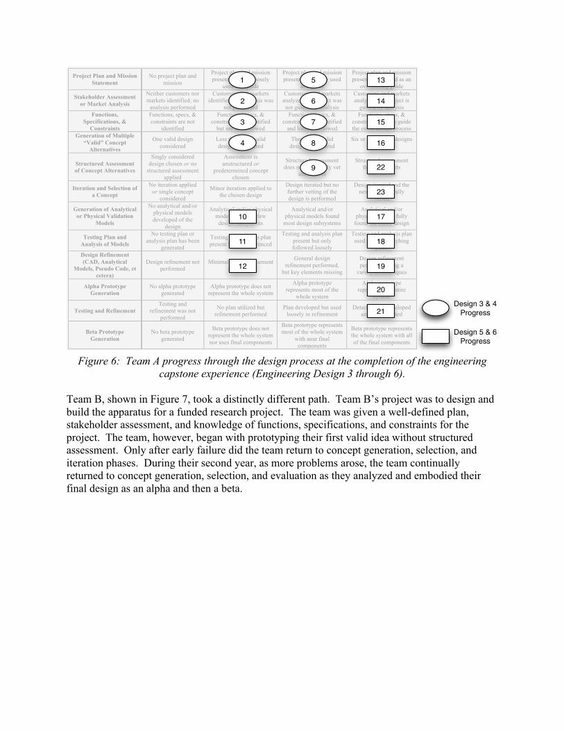
Figure 6: Team A progress through the design process at the completion of the engineering
capstone experience (Engineering Design 3 through 6).
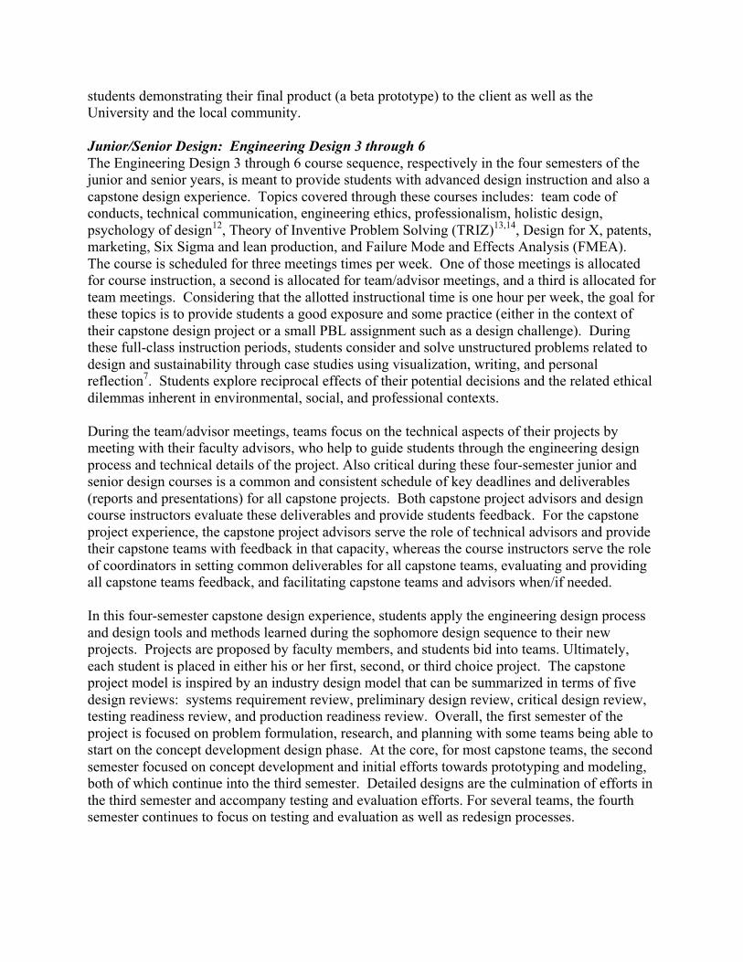
Team B, shown in Figure 7, took a distinctly different path. Team B’s project was to design and build the apparatus for a funded research project. The team was given a well-defined plan, stakeholder assessment, and knowledge of functions, specifications, and constraints for the project. The team, however, began with prototyping their first valid idea without structured assessment. Only after early failure did the team return to concept generation, selection, and iteration phases. During their second year, as more problems arose, the team continually returned to concept generation, selection, and evaluation as they analyzed and embodied their final design as an alpha and then a beta.
Project Plan and Mission Statement
No project plan and mission
Project plan and mission present but only loosely
used as a guide
Project plan and mission present and mostly used
as a guide
Project plan and mission presented and used as an
overarching guide
Stakeholder Assessment or Market Analysis
Neither customers nor markets identified; no
analysis performed
Customers and markets identified, but analysis was
not performed
Customers and markets analyzed but project was not guided by analysis
Customers and markets analyzed and project is
guided by analysis Functions,
Specifications, & Constraints
Functions, specs, & constraints are not
identified
Functions, specs, & constraints are identified
but are not followed
Functions, specs, & constraints are identified
and loosely followed
Functions, specs, & constraints help to guide the entire design process
Generation of Multiple “Valid” Concept
Alternatives
One valid design considered
Less than three valid designs considered
Three to six valid designs considered
Six or more valid designs considered
Structured Assessment of Concept Alternatives
Singly considered design chosen or no
structured assessment applied
Assessment is unstructured or
predetermined concept chosen
Structured assessment does not thoroughly vet
alternatives
Structured assessment thoroughly vets
alternatives
Iteration and Selection of a Concept
No iteration applied or single concept
considered
Minor iteration applied to the chosen design
Design iterated but no further vetting of the design is performed
Design iterated and the new design is fully
vetted
Generation of Analytical or Physical Validation
Models
No analytical and/or physical models developed of the
design
Analytical and/or physical models found on few
design subsystems
Analytical and/or physical models found
most design subsystems
Analytical and/or physical models fully
found the entire design
Testing Plan and Analysis of Models
No testing plan or analysis plan has been
generated
Testing and analysis plan present but not referenced
Testing and analysis plan present but only followed loosely
Testing and analysis plan used as an overarching
guide Design Refinement (CAD, Analytical
Models, Pseudo Code, et cetera)
Design refinement not performed
Minimal design refinement performed
General design refinement performed,
but key elements missing
Design refinement performed using a
variety of techniques
Alpha Prototype Generation
No alpha prototype generated
Alpha prototype does not represent the whole system
Alpha prototype represents most of the
whole system
Alpha prototype represents the entire
system
Testing and Refinement Testing and
refinement was not performed
No plan utilized but refinement performed
Plan developed but used loosely in refinement
Detailed plan developed and implemented
Beta Prototype Generation
No beta prototype generated
Beta prototype does not represent the whole system nor uses final components
Beta prototype represents most of the whole system
with near final components
Beta prototype represents the whole system with all of the final components
!
1
10
2
3
4
5
6
7
8
9
11
12
13
14
15
16
17
18
19
20
21
22
23
Design 3 & 4 Progress
Design 5 & 6 Progress
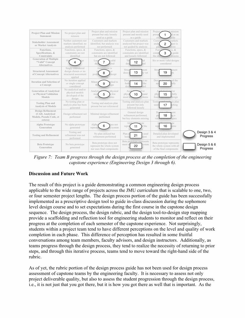
Figure 7: Team B progress through the design process at the completion of the engineering
capstone experience (Engineering Design 3 through 6). Discussion and Future Work The result of this project is a guide demonstrating a common engineering design process applicable to the wide range of projects across the JMU curriculum that is scalable to one, two, or four semester project lengths. The design process portion of the guide has been successfully implemented as a prescriptive design tool to guide in-class discussion during the sophomore level design course and to set expectations during the first course in the capstone design sequence. The design process, the design rubric, and the design tool-to-design step mapping provide a scaffolding and reflection tool for engineering students to monitor and reflect on their progress at the completion of each semester of the capstone experience. Not surprisingly, students within a project team tend to have different perceptions on the level and quality of work completion in each phase. This difference of perception has resulted in some fruitful conversations among team members, faculty advisors, and design instructors. Additionally, as teams progress through the design process, they tend to realize the necessity of returning to prior steps, and through this iterative process, teams tend to move toward the right-hand side of the rubric. As of yet, the rubric portion of the design process guide has not been used for design process assessment of capstone teams by the engineering faculty. It is necessary to assess not only project deliverable quality, but also to assess the student progression through the design process, i.e., it is not just that you got there, but it is how you got there as well that is important. As the
Project Plan and Mission Statement
No project plan and mission
Project plan and mission present but only loosely
used as a guide
Project plan and mission present and mostly used
as a guide
Project plan and mission presented and used as an
overarching guide
Stakeholder Assessment or Market Analysis
Neither customers nor markets identified; no
analysis performed
Customers and markets identified, but analysis was
not performed
Customers and markets analyzed but project was not guided by analysis
Customers and markets analyzed and project is
guided by analysis Functions,
Specifications, & Constraints
Functions, specs, & constraints are not
identified
Functions, specs, & constraints are identified
but are not followed
Functions, specs, & constraints are identified
and loosely followed
Functions, specs, & constraints help to guide the entire design process
Generation of Multiple “Valid” Concept
Alternatives
One valid design considered
Less than three valid designs considered
Three to six valid designs considered
Six or more valid designs considered
Structured Assessment of Concept Alternatives
Singly considered design chosen or no
structured assessment applied
Assessment is unstructured or
predetermined concept chosen
Structured assessment does not thoroughly vet
alternatives
Structured assessment thoroughly vets
alternatives
Iteration and Selection of a Concept
No iteration applied or single concept
considered
Minor iteration applied to the chosen design
Design iterated but no further vetting of the design is performed
Design iterated and the new design is fully
vetted
Generation of Analytical or Physical Validation
Models
No analytical and/or physical models developed of the
design
Analytical and/or physical models found on few
design subsystems
Analytical and/or physical models found
most design subsystems
Analytical and/or physical models fully
found the entire design
Testing Plan and Analysis of Models
No testing plan or analysis plan has been
generated
Testing and analysis plan present but not referenced
Testing and analysis plan present but only followed loosely
Testing and analysis plan used as an overarching
guide Design Refinement (CAD, Analytical
Models, Pseudo Code, et cetera)
Design refinement not performed
Minimal design refinement performed
General design refinement performed,
but key elements missing
Design refinement performed using a
variety of techniques
Alpha Prototype Generation
No alpha prototype generated
Alpha prototype does not represent the whole system
Alpha prototype represents most of the
whole system
Alpha prototype represents the entire
system
Testing and Refinement Testing and
refinement was not performed
No plan utilized but refinement performed
Plan developed but used loosely in refinement
Detailed plan developed and implemented
Beta Prototype Generation
No beta prototype generated
Beta prototype does not represent the whole system nor uses final components
Beta prototype represents most of the whole system
with near final components
Beta prototype represents the whole system with all of the final components
!
1
2
3
4
5
6
7
8
9
10
11
12
13
14
15
16
17
18
19
20
21
22
Design 3 & 4 Progress
Design 5 & 6 Progress
rubric begins to be used as an assessment tool in addition to an educational tool, it will become necessary to measure inter-rater reliability, and potentially iterate the rubric to ensure consistency between both faculty and external capstone project evaluators. Bibliography 1. National Academy of Engineering. The Engineer of 2020: Visions of Engineering in the New Century.
Washington DC: National Academies Press; 2004. 2. National Academy of Engineering. Educating the Engineer of 2020: Adapting Engineering Education to
the New Century. Washington D.C.: The National Academies Press; 2005. 3. Pierrakos O, Kander R, Pappas E, Prins R. An Innovative Engineering Curriculum at James Madison
University: Transcending Disciplinary Boundaries Through Innovative Problem Based Learning Practices. ASME International Mechanical Engineering Congress & Exposition. Boston, MA2008.
4. Nagel RL, Pierrakos O, Pappas E, Nagel JK. On a Client-Centered, Sophomore Design Course Sequence. 119th ASEE Annual Conference & Exposition. San Antonio, TX: ASEE; 2012.
5. Pierrakos O, Nagel RL, Pappas E, Nagel JK. A New Vision for Engineering Design Instruction: On the Innovative Six Course Design Sequence of James Madison University. 119th ASEE Annual Conference & Exposition. San Antonio, TX2012.
6. Nagel RL, Pappas EC, Pierrakos O. On a Vision to Educating Students in Sustainability and Design—The James Madison University School of Engineering Approach. Sustainability. 2012;4(1):72-91.
7. Nagel RL, Pierrakos O, Pappas EC, Ogundipe A. The Integration of Sustainability, Systems, and Engineering Design in the Engineering Curriculum at James Madison University. ASME 2011 International Design Engineering Technical Conferences (IDETC). Vol DECT2011. Washington, DC: ASME; 2011.
8. Nagel J, Nagel R, Pappas E, Pierrakos O. Integration of a Client-based Design Project into the Sophomore Year. ASME 2012 International Design Engineering Technical Conferences (IDETC). Vol 2012. Chicago, IL: ASME; 2012.
9. Shah JJ, Vargas-Hernandez N, Summers JD, Kulkarni S. Collaborative Sketching (C-Sketch) - An Idea Generation Technique for Engineering Design. The Journal of Creative Behavior. 2001;35(3):168-198.
10. Pugh S. Total Design: Integrated Methods for Successful Product Engineering. Wokingham, England: Addison-Wesley Publishing Company; 1991.
11. Dassault Systèmes SolidWorks Corp. 3D CAD Design Software SolidWorks. 2011; http://www.solidworks.com/. Accessed Jan. 5, 2011.
12. Norman DA. The Design of Everyday Things. New York: Basic Books; 2002. 13. Altshuller G. Creativity As An Exact Science: The Theory of the Solution of Inventive Problems.
Luxembourg: Gorden and Breach Science Publishers Inc.; 1995. 14. Altshuller G. 40 Principles (Extended Edition): TRIZ Keys to Technical Innovation. Worcester, MA:
Technical Innovation Center, Inc.; 2005. 15. Nagel RL, Poppa K, Stone RB. Teaching Multiple Approaches to Engineering Design within a Unified
Curriculum. ASME 2010 International Design Engineering Technical Conferences (IDETC). Vol DETC2010. Montreal, Quebec, Canada: ASME; 2010.
16. Pahl G, Beitz W, Feldhusen J, Grote KH. Engineering Design: A Systematic Approach. 3rd ed: Springer Verlag; 2007.
17. Suh N. The Principles of Design. New York, NY: Oxford University Press, Inc.; 1990. 18. Suh NP. Axiomatic Design: Advances and Applications. New York: Oxford University Press; 2001. 19. Ulwick AW. What Customers Want: Using Outcome-Driven Innovation to Create Breakthrough Products
and Services. New York: McGraw-Hill; 2005. 20. Ulwick AW. Turn Customer Input into Innovation. Harvard Business Review. 2002;80(1):91-97 21. Dieter G. Engineering Design: A Materials and Processing Approach. 2nd ed. New York: McGraw-Hill;
1991. 22. Dym CL, Little P. Engineering Design: A Project-based Introduction. Hoboken: John Wiley & Sons,
INC.; 2009.
23. Earle JH. Engineering Design Graphics. Reading, Mass: Addison Wesley; 1990. 24. Hill PH. The Science of Engineering Design. New York: Holt, Rinehart and Winston; 1970. 25. Hyman B. Fundamentals of Engineering Design. Upper Saddle River, New Jersey: Prentice Hall; 1998. 26. Lindbeck. Product Design and Manufacturing. Englewood Cliffs, NJ: Prentice Hall; 1994. 27. Niku SB. Creative Design of Products and Systems. Hoboken, NJ: John Wiley & Sons, Inc.; 2009. 28. Otto K, Wood K. Product Design: Techniques in Reverse Engineering, Systematic Design, and New
Product Development. New York: Prentice-Hall; 2001. 29. Ullman DG. The Mechanical Design Process. 4th ed. Boston: McGraw-Hill; 2010. 30. Ulrich KT, Eppinger SD. Product Design and Development. 3rd ed. Boston, MA: McGraw-Hill/Irwin;
2004. 31. Voland G. Engineering By Design. 2nd ed. Upper Saddle River, NJ: Pearson Prentice Hall; 2004. 32. Dieter GE, Schmidt LC. Engineering Design. 5 ed. New York: McGraw-Hill; 2012. 33. Asimow M. Introduction to Design. Englewood Cliffs, NJ: Prentice-Hall; 1962.
Engineering Capstone Project Guide
No project plan and mission
Project plan and mission present but only loosely used as
a guide
Project plan and mission present
and mostly used as a guide
Project plan and mission presented
and used as an overarching guide
Neither customers nor markets
identified; no analysis performed
Customers and markets identified,
but analysis was not performed
Customers and markets analyzed
but project was not guided by analysis
Customers and markets analyzed
and project is guided by analysis
Functions, specs, & constraints are not
identified
Functions, specs, & constraints are
identified but are not followed
Functions, specs, & constraints are
identified and loosely followed
Functions, specs, & constraints help to
guide the entire design process
One valid design considered
Less than three valid designs considered
Three to six valid designs considered
Six or more valid designs considered
Singly considered design chosen or no
structured assessment applied
Assessment is unstructured or predetermined concept chosen
Structured assessment does
not thoroughly vet alternatives
Structured assessment
thoroughly vets alternatives
No iteration applied or single concept
considered
Minor iteration applied to the chosen
design
Design iterated but no further vetting of the design is
performed
Design iterated and the new design is
fully vetted
No analytical and/or physical models developed of the
design
Analytical and/or physical models
found on few design subsystems
Analytical and/or physical models
found most design subsystems
Analytical and/or physical models fully found the entire design
No testing plan or analysis plan has been generated
Testing and analysis plan present but not
referenced
Testing and analysis plan
present but only followed loosely
Testing and analysis plan used as an overarching
guide
Design refinement not performed
Minimal design refinement performed
General design refinement
performed, but key elements missing
Design refinement performed using a
variety of techniques
No alpha prototype generated
Alpha prototype does not represent the
whole system
Alpha prototype represents most of the whole system
Alpha prototype represents the entire system
Testing and refinement was not
performed
No plan utilized but refinement performed
Plan developed but used loosely in
refinement
Detailed plan developed and implemented
No beta prototype generated
Beta prototype does not represent the whole system nor
uses final components
Beta prototype represents most of the whole system
with near final components
Beta prototype represents the
whole system with all of the final components
Stakeholder Assessment or Market Analysis
Functions, Specifications, &
Constraints
Generation of Multiple "Valid" Concept
Alternatives
Structured Assessment of Concept Alternatives
Iteration and Selection of a Concept
Testing Plan and Analysis of Models
Generation of Analytical or Physical
Validation Models
Design Refinement (CAD, Analytical
Models, Pseudo Code)
Alpha Prototype Generation
Testing and Refinement
Beta Prototype Generation
Sem
este
r 1 -
Des
ign
III -
EN
GR
331
Sem
este
r 2 -
Des
ign
IV -
EN
GR
332
Sem
este
r 3 -
Des
ign
V -
EN
GR
431
Sem
este
r 4 -
Des
ign
VI -
EN
GR
432
Project Plan and Mission Statement
Typi
cal T
ime
Sca
le a
nd T
raje
ctor
y
Pla
nnin
g an
d In
form
atio
n G
athe
ring
Con
cept
Gen
erat
ion,
E
valu
atio
n, a
nd S
elec
tion
Des
ign
Em
bodi
men
tTe
stin
g an
d R
efine
men
t
Engineering Capstone Project Guide
Stakeholder Assessment or Market Analysis
Functions, Specifications, &
Constraints
Generation of Multiple "Valid" Concept
Alternatives
Structured Assessment of Concept Alternatives
Iteration and Selection of a Concept
Testing Plan and Analysis of Models
Generation of Analytical or Physical
Validation Models
Design Refinement (CAD, Analytical
Models, Pseudo Code)
Alpha Prototype Generation
Testing and Refinement
Beta Prototype Generation
Sem
este
r 1 -
Desig
n III
- EN
GR 3
31Se
mes
ter 2
- De
sign
IV -
ENGR
332
Sem
este
r 3 -
Desig
n V
- ENG
R 43
1Se
mes
ter 4
- De
sign
VI -
ENGR
432
Project Plan and Mission Statement
Typi
cal T
ime
Scal
e an
d Tr
ajec
tory
1. Gantt Chart
2. Critical Path 5. Risk Assessment
3. Budget 6. Cash Flow Assessment
1. Customer Needs
2. Stakeholder Analysis
3. Market Analysis
4. Network Diagram
4. Affinity Diagram
1. Functional Modeling
3. Need to Function to Specification Mapping
4. Function Enumeration
2. Codes and Standards
TypicalDesign Process
Potential Tools and Methods
1. Morphological Matrices 4. Design Catalogs
3. Design by Analogy (Biomimicry, TRIZ, etc.)
2. 6-3-5 / C-Sketch 5. Benchmarking
4. Benchmarking
5. House of Quality
5. House of Quality
1. Pugh Chart
2. Decision Matrices
3. Proof of Concept
5. Codes and Standards
4. Benchmarking1. Pugh Chart
2. Decision Matrices
3. Proof of Concept
5. Codes and Standards
6. Technical Feasibility
6. Technical Feasibility
1. Proof of Concept (Rapid Prototypes, Mock-ups, etc.)
2. Software Models (CAD, Simulation, etc.)
1. Design of Experiments
2. Finite Element Analysis
3. Numerical Analysis (Circuit, Flow Rate, Stress, etc.)
3. Failure Modes and Effects Analysis
1. Design for X Analysis
2. Software Models (CAD, Simulation, Optimization, etc.)
3. Numerical Analysis (Circuit, Flow Rate, Stress, etc.)
1. Design of Experiments
1. System-level Functional Prototype
1. System-level Functional Prototype
Typical Design Phases
Plan
ning
and
Info
rmat
ion
Gath
ering
Conc
ept G
ener
ation
, Ev
aluat
ion, a
nd S
electi
onDe
sign
Embo
dimen
tTe
sting
and
Refi
nem
ent
4. Simulations
2. Failure Modes and Effects Analysis