Embed Size (px)
Citation preview
RATIONAL AERONAUtlCM FITAUlmMCNf
,LIBRAWY, lKB SEP I954
C.P. No. 469 (16.777)
ARC Technkal Report
MINISTRY OF SUPPLY
AERONAUTICAL RESEARCH COUNCIL
CURRENT PAPERS
A Variable Inductance Acceleration Transducer
BY .
H. K. P. Neubert, Dr.-kg
LONDON: HER MAJESTY’S STATIONERY OFFICE
1954 .
Price 2s. Qd. net

C.P. No. 109
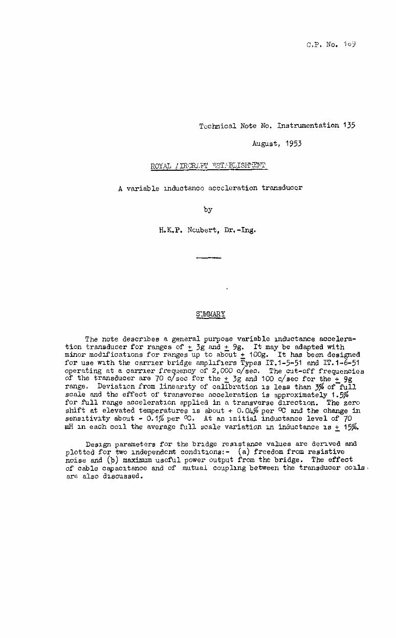
Technical Note No. Instrumentation 135
J-w.=% 1953
A variable lnductsncc accclemtion transducer
H.K.P. Ncubert, Dr.-In&
The note describes a general purpose variable inductance accelera- tion transducer for rsnges of +- 3g snd + Yg. It may be adapted with minor modifications for ranges up to about + 1OOg. It has been designed for use with the carrier bridge amplifiers Types IT.l-5-51 and IT.i-6-51 operating at a oarrier fre uency of 2,000 c/set. of the transducer are 70 o 3
The cut-off frequenoics set for the + 3g and 100 c/sea for the + Yg
range, Deviation from linearity of cal.?bration is less than 3% of-full scale snd the effect of transverse acceleration is approximately 1.5% for full rsnge acceleration applied in a transverse direction. The zero shift at elevated temperatures is about + O.O&per Oc and the change in sensitivity about - 0.1% per Oc. At an initial. inductance level of 70 ah in each coil the average full scale variation in inductance is + 15%.
Design parameters for the bridge resistance values are derived and plotted for two independent conditions:- (a) freedom from resistive noise and (b) maximum useful power output from the bridge. The effect of cable capacitance and of mutual coupling between the trsnsduoer tolls, are also discussed.

LIST OF CONCERTS
1 Introduction
2 Description
3 Mechsnioal characteristics
3.1 Range and linearity
3.2 Frequency response
3.3 Transverse sensitivity
3.4 Temperature sensitivity
4 Electrioal characteristics
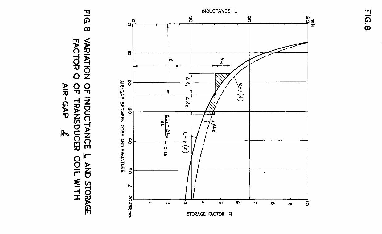
4.1 Variation of inductance and storage factor
4.2 Current sensitivity
4.3 Power sensitivity
4.4 Effect of mutual coupling between transducer coils
4.5 Effect of cable capaoitancc
References
P*
3
3
3
3
4
4
4
5
5
6‘
LIST OF ILLUSTRATIONS --- - F-
Construction of acoeleratmn transducer Type IT.i-22F-31 1 Photo raph of
b
2 a complete transducer b exploded transducer
Typical calibration curve of transducer Useful Nnplitude ranges of transducer for various frequencies 2 Frequency respcnsc of transducer to sinusoidal acceleration 5 Variation of damping ratio of tr,snsduoer with temperature 6 Impedance of transducer ccrl
(a) at various frequencies 7
(b) at various air gaps Variaticn,cf .induotance and storage factor of transducer coil with 8
9
IO
11
-2-

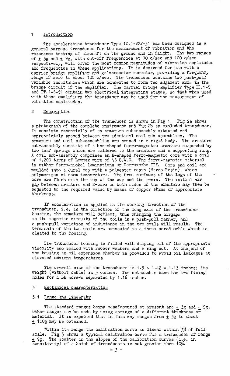
I Introduction
The acceleration transducer Type IT.l-22F-31 has been designed as a general purpose transducer for the measurement of vibration and the resonance testing of aircraft on the ground and in flight. The two ranges of + 3g and + Pg, with cut-off frequencies at 70 c/set and 100 c/set respectively; will cover the most common magnitudes of vibration sn@itudes and frequenoles in these applications. It is designed for use with a carrier bridge smplifier and galvsnometer reCOrder, providing a frequen"y range of eero to about 100 c/set. The transducer contains two push-pull variable inductances whioh are connected to form two adJacent arms in the bridge circuit of the amplifier. The carrier bridge amplifier Type IT.1 -5 and IT.l-6-51 contain two electrical integrating stages, so that when used with these amplifiers the transducer msy bc used for the measurement of vibration smplitudes.
2 Description
The construction of the transducer is shown in Fig 1. Fig 2a shows a photograph of the complete instrument and Fig 2b an exploded transducer. It consists essentially of an armature sub-assembly situated and appropriately spaced between two adentical coil sub-assemblies. The armature end coil sub-assemblies are housed in a rigid body. The armature sub-assembly consists of a bar-shaped ferro-magnetic armature suspended by two leaf springs which are soldered to the armature and a supporting ring. A coil sub-assembly comprises an E-shaped ferro-m,agnetic core with a coil of 1,200 turns of Lewmex wire of 46 S.W.G. The fen-o-magnetic material is either ferro-nickel laminations or Ferroxcube III. Core and coil are moulded into a dural cup with a polyester resin (Eharco Resin), which polymerises at room temperature. The free surfaces of the legs of the . core iare flush with the top of the cup and the resin. The initial air gap between armature and E-core on both sides of the armature may then be adJustCd to the required value by mesns of copper shims of appropriate thickness.
If acceleration 1s applied in the working direction of the transducer, i.e. in the direction of the long axis of the transducer housing, the armature will deflect, thus changing the airgaps in the mngnetic osrcuits of the coils in a push-pull manner, and a push-pull variation of mductsnce 111 the two coils will result. The terminals of the two coils sre connected to a three cored cable which is cleated to the housing.
The transducer housing is flllcd with damping oil of the appropriate viscosity and sealed with rubber washers and a ring nut. At one,end of' the housing 3~. oil expansion chamber IS provided to avoid 011 leakages at elevated smbient temperatures.
The overall siee of the transducer is I.9 x 1.42 x 1 .I3 inches; its weight (wlthout cable) I.E 3 ounces. The detachable base has two fixing holes for 4 BA sorews separated by 1.16 inches.
3 Mechanical characteristics
3.1 Rwe sndlinear~
The standard ranges being manufactured at present are + 3g end +- 99. Other ranges may be made by using springs of a different tgokness or material. It is expected that in this way ranges from + 39 to shout +- IOOg may be obtained.
Within its range the calibration curve is linear within 3% of full scale. Fig 3 shows a typlcsl calibration curve for a transducer of range + Tg. The scatter in the slopes of the calibration curves (i.e. U-I sensitivity) of a batch of transducers IS not greater then I@.
-3-
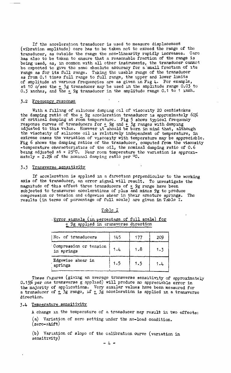
If the acceleration transducer is used to measure displacement (vibration amplitude) care has to be taken not to exceed the range of the transducer, as outside the range the non-linearity rapidly increases. Care has also to be taken to ensure that a reasonable fraction of the range is being used, as, in common with all other instruments, the transducer cannot be expected to give the same absolute accuracy for a-small fraction of its
range as for its full range. Taking the usable range of the transducer as from 0.1 times full range to full range, the upper and lower limits of amplitude at various frequencies are as given in Fig 4. For example, at IO c/set the t jg transducer may be used in the amplitude range 0.03 to 0.3 aches, and The +- gg transducer in the amplitude range 0.1 to 1 inch.
3.2 Frequencv resuonse
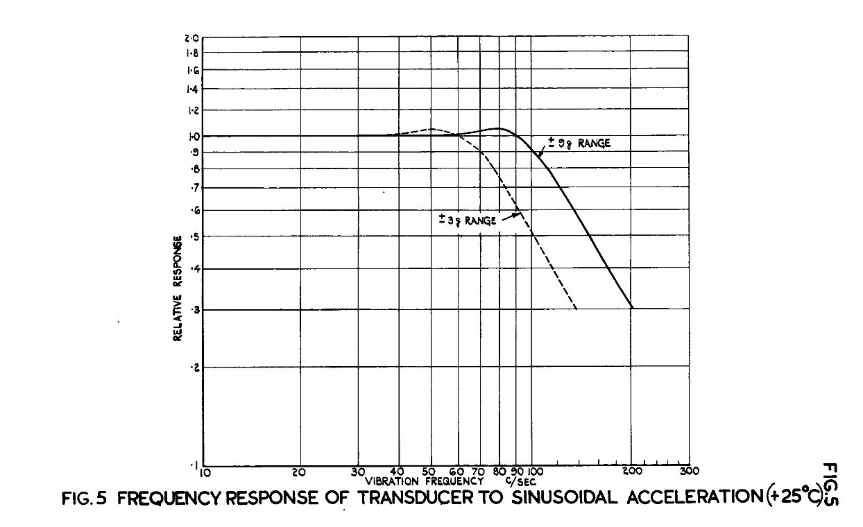
With a filling of salicone damping oil of viscosity 20 centistokes the damping ratio of the + 9g acceleration transducer is approximately 60% of critical damping at room temperature. Fig 5 shows typical frequency response curves of transducers for t 9g and +- 3g ranges with damping adjusted to this value. However It should be born in mind that, although the viscbsity of silicone oil is relatively independent of temperature, in extreme cases the variation of viscosity with temperature may be apprecisble. Fig 6 shows the damping ratios of the transducer, computed from the viscosity -temperature ch<aracteristics of the oil, being adjusted at + 2.5%.
the nominal damping ratio of 0.6 Near room temperature the vsriation is spproxi-
mately - 2.23 of the nominal damping ratio per OC.
3.3 Tmsverse sensitivity
If acceleration is applied in a direction perpendicular to the working axis of the transducer, an error signal will result. To investigate the magnitude of this effect three transducers of +- 9g range have been subjected to transverse accelerations of plus snd minus gg to produce compression or tension end edgewioe shear in their armature sprangs. The results (in terms of percentage of full scnle) are given in Tsble I.
Table I
.Error signals (in Dercentage of full scale) for t 9g applied in cransvcrse direction
No. of transducers 145 177 209
'Compression or tension in springs 1.4 1.8 I.3
Edgewise shear in 1 springs / 1.5 1.5 1.4
These figures (giving en average transverse sensitivity of approximately C.i5$ per one transverse g applied) will produce no appreciable error in the majority of applicaticnS. Very similar values have been measured for a trsnsducer of +, 3g rsnge, if +- 3g acceleration is applied an a transverse direction. 3.4 Temperature sensitivity
A change in the temperature of a ‘mu&UCer may result in two effects: (a) Variation of zero setting under the no-load condition. (zero-shift)
(b) Variation of slope of the calibration curve (variation in sensitivity)
-4-
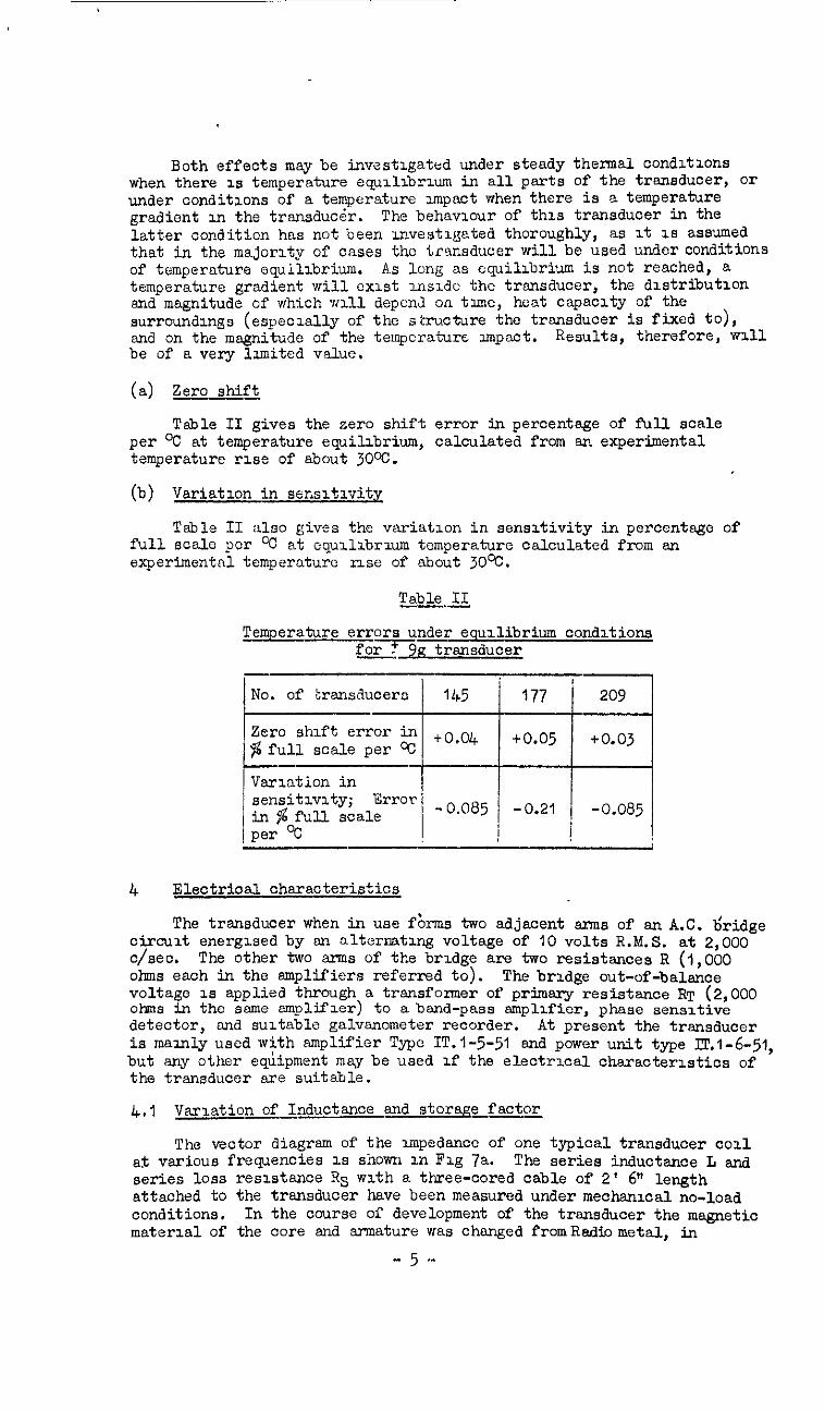
Both effects may be investigated under steady thermal conditions when there is temperature equilibrium in all parts of the transducer, Or
under conditions of a temperatur e impact when there is a temperature gradient in the transducer. The behaviour of this transducer in the latter condition has not been investigated thoroughly, as it as assumed that in the majority of cases the transducer will be used under conditions of temperature equilibrium. As long as equilibrium is not reached, a temperature gradient will exist inside the transducer, the dlstributlon and magnitude of which will depcnJ on time, heat capacity of the surroundings (especially of the structure the transducer is fixed to), and on the magnitude of the temperature Impact. Results, therefore, will be of a very limited value.
(a) Zero shift
Table II gives the sero shift error in percentage of full scale per oC at temperature equilibrium, calculated from sn experimental temperature rise of about 30%.
(b) Variation in sensitlvite
Table II also gives the variation in sensitivity in percentage of full SC&Z pCr % at equilibriwn temperature calculated from an experimentnl temperature nse of about 30%.
Table II ---
Temperature errors under ecuilibrium conditions forfg transducer
4 Electrioal~cteristics
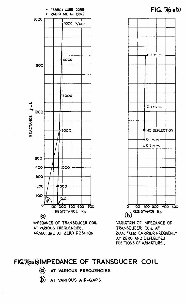
The transducer when in use fbrms two adjacent arms of an A.C. b'ridge circuit energised by sn alternating voltage of 10 volts R.M.S. at 2,000 o/set. The other two arms of the bridge are two resistances R (1,000 ohns each in the amplifiers referred to). The bridge out-of-balance voltage is applied through a trsnsfonaer of primary resistance RT (2,000 ohms in the same amplifier) to a band-pass amplifier, phase sensitive detector, and suitable galvsnometer recorder. At present the transducer is mainly used with amplifier Type IT.l-5-51 and power unit type ml-6-51, but any other eqiipment may be used lf the electrxal charaoterlstics of the transducer are suitable.
4.1 Variation of Inductance and storage factor
The veotor diagram of the impedsnoc of one typical transducer coil af various frequencies 1s shown m Fig Ta. The series inductance L snd series loss reslstsnce Rs with a three-cored cable of 2' 6" length attached to the transducer have been measured under mechanxal no-load conditions. In the course of development of the transducer the magnetic material of the core and annature was changed PromRadiometal, in
-5"
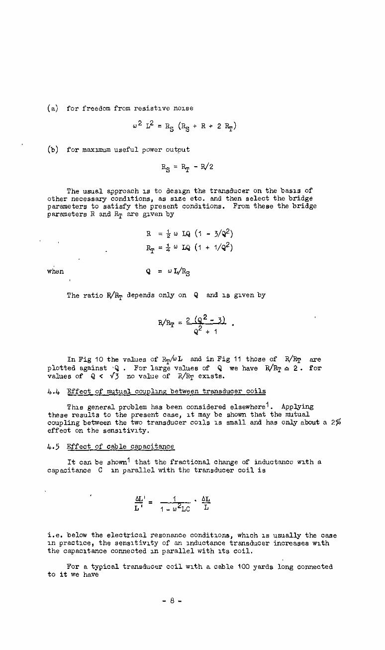
(a) for freedom from resistive noise
.* L* = RS (RR + R + 2 RT)
(b) for maxxmum useful power output
Rs=RT-R/2
The usual approach is to design the transducer on the basis of other necessary conditions, as size etc. and then select the bridge parameters to satisfy the present conditions. From these the bridge parsmeters X and RT are givenby
R = $ w XQ (1 - 3/Q*)
when Q = wL/RR
The ratio R/RT depends only on Q and 1s givenby
In Fig 10 the values of RT/WL and in Fig 11 those of R/RT are plotted against ~Q . For large values of Q we have R&T c 2. for values of Q < \‘5 no value of R/Pq exists.
4.4 Effect of mutual coupling between transducer coils
This general problem has been considered elsewhere'. Applying these results to the present case, It may be shown that the mutual coupling between the two transducer coils 1s small and has only about a 2$ effect on the sensitivity.
4.5 Effect of cable capacitance
It can be shown' that the fractional change of inductance with a capacitance C in parallel with the transducer coil is
i.e. below the electrical resonance conditions, whxh IS usually the case in practice, the sensitivity of an inductance transducer increases with the capacitance connected m parallel with its coil.
For a typical transducer coil with a cable 100 yards long connected to it we have
-8-
L = 64 mIi at 2,000 c/set
c = 0.005 p n
u = 2;; 2,000 set -1
i.e. jn increase in sensitivity 0;‘ 5%. This has been verified experimentally in the present case.
No. - Author Title, etc.
1 H.K.P. Neubert Design and. performance of inductance pick-ups and their associated circuits. S.A.E. F&port No. Instruwntation 7.

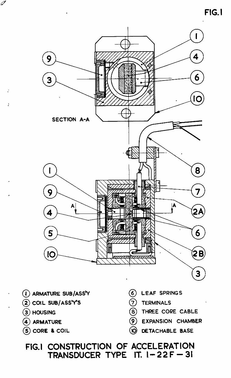
FIG. I
SECTION A-A \ /
‘0 28 \
‘0 3
0 J ARMATURE SUB/ASSh, 0 6 LEAF SPRINGS
0 2 COIL SUS/ASS’Y% 0 7 TERMINALS
0 3 HOUSING 0 8 THREE CORE CABLE
0 4 ARMATURE 0 9 EXPANSION CHAMBER
0 5 CORE 6 COIL 0 IO DETACHABLE BASE
FIG.1 CONSTRUCTION OF ACCELERATION TRANSDUCER TYPE IT. 1.022 F - 31
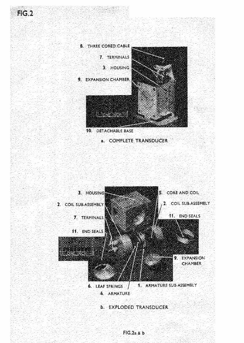
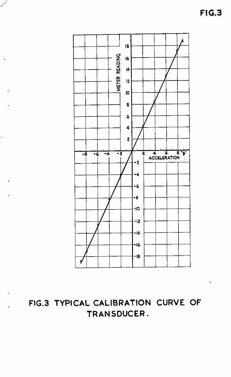
FIG.3
FIG.3 TYPICAL CALIBRATION CURVE OF TRANSDUCER.
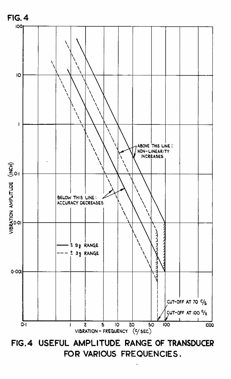
FIG. 4
‘!
\ \
\ Y- \ \ \
rCCURACY DECREASES
i-l -+-So RANGE --- +, 31 RANGE
tl L I 2 5 7
l-
L-
\ Y \
I-
,/’ \ ,
\
0 -3 VIBRATION - FREQUENCY
/ABOVE MIS I NON-LINEAF
INCREASE!
JNI lITI 5
j- / , / I / I I I I I I
( /
/C
lO(
:.
I
-
-
-
:UT-OFF AT 70 C/S
;UT-OFF AT 100 ‘/s I I
1 IO1
FIG.4 USEFUL AMPLITUDE RANGE OF TRANSDUCER FOR VARIOUS FREQUENCIES.
-
-
-
-
1 'IO 20 30
“lB&iON 5PEc+.f
FIG.5 FREQUENCY RESPONSE OF TRANSDUCI
-
-
-
- r w EC
3 : 3 3 TO SINUSOIDAL ACCELERATION (+25’&
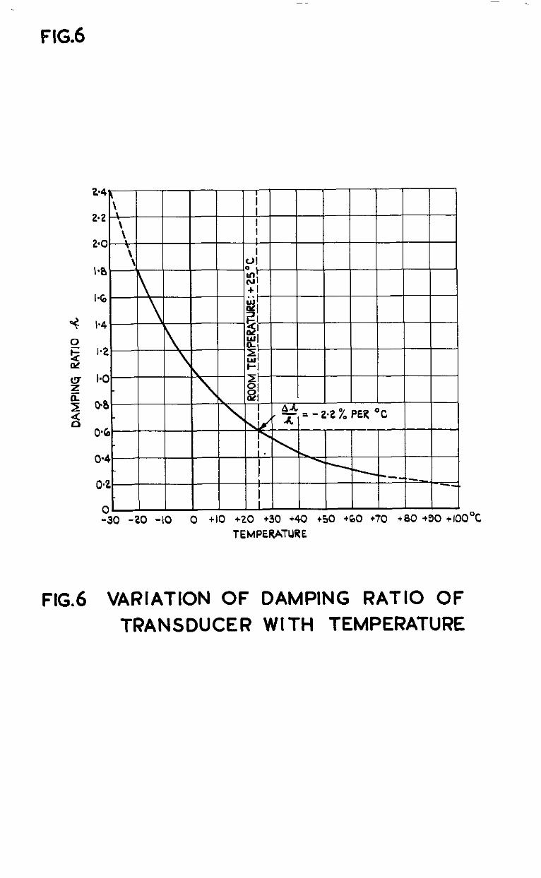
FIG.6
TEMPERATURE
FIG.6 VARIATION OF DAMPING RATIO OF TRANSDUCER WITH TEMPERATURE
0 FERROX CUBE CORE x RADIO METAL CORE
2000 I I ~000 C/SEC
RESISTANCE R s
@ IMPEDANCE OF TRANSDUCER COIL AT VARlOU3 FREQUENCIES. ARMATURE AT ZERO POSITION
1 0
FIG. 7@ a b)
6) RESISTANCE Rs
VARIATION OF IMPEDANCE OF TR4NSDUCEFi: COIL AT 2000 ‘/SEC CARRIER FREQUENCY AT ZERO AND DEFLECTED WSITIONS OF ARMATURE .
FIG7~rb)lMPEDANCE OF TRANSDUCER COIL (a> AT VARIOUS FREOUENCIES
0 AT VARIOUS AIR-GAPS
;-
i- I
INDUCTANCE L
T--Y---
- N G, a ul 63 rl ID cp
STORAGE FACTOR Q
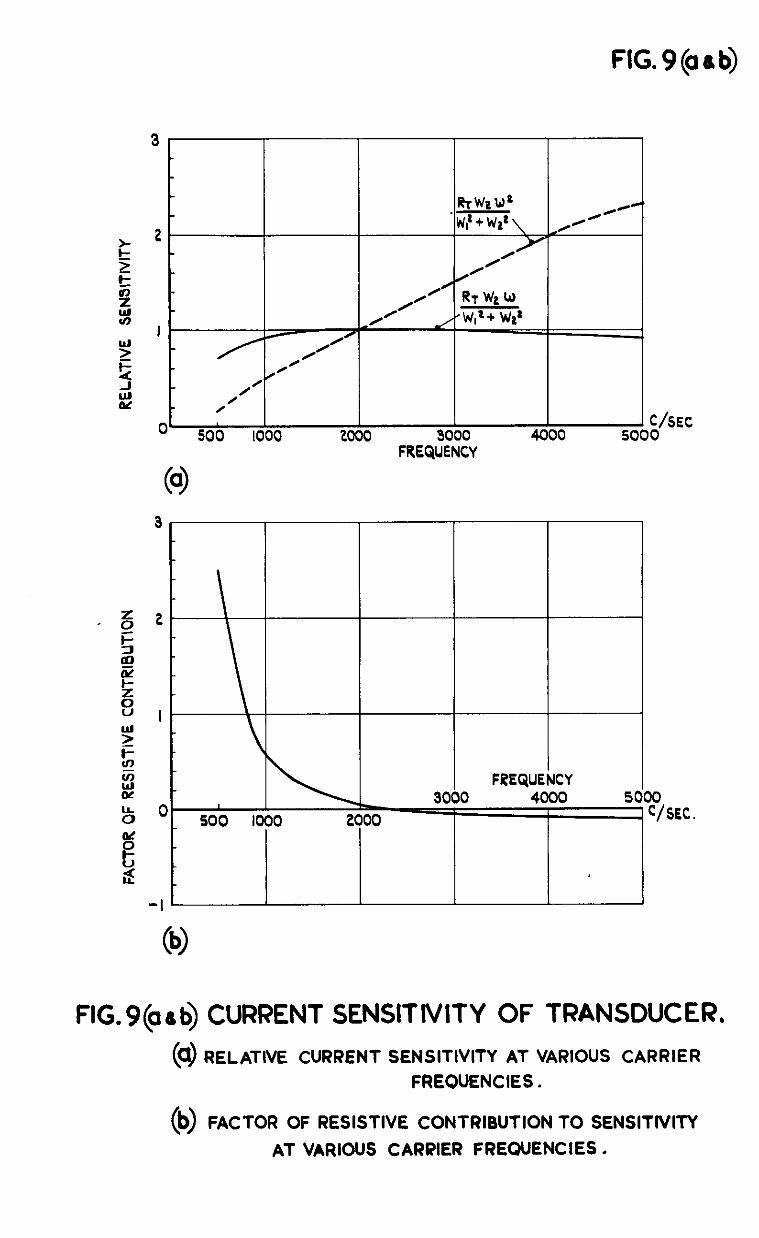
FIG9(aab)
0 C/SEC 500 1000 2000 3000 4000 5000
FREQUENCY
3
2 .
I
0 _ 500 II
-I ’
\ loI I
FREQUENCY 3000 4000 5 -.-
3 2000 IO C/SEC.
FIG9@ati) CURRENT SENSITIVITY OF TRANSDUCER.
(c13 RELATIVE CURRENT SENSITIVITY AT VARIOUS CARRIER FREQUENCIES.
0 FACTOR OF RESISTIVE CONTRIBUTION TO SENSITNITY
AT VARIOUS CARRIER FREQUENCIES.
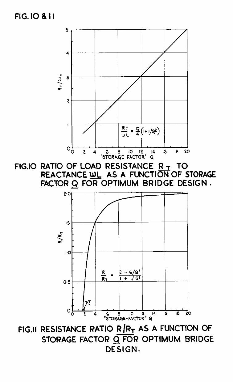
FIG. IO & I I
FIG.10
FIG.11
I’ ’ 8 1” c 1” ” * ” ‘I 1 Oo 2 4
“S~ORA& &&* : 16 10 20
RATIO OF LOAD RESISTANCE & TO REACTANCE WJ AS A FUNCTION OF STORAGE FACTOR9 FOR OPTIMUM BRIDGE DESIGN l
RESISTANCE RATIO RIRT AS A FUNCTION OF STORAGE FACTOR Q FOR OPTIMUM BRIDGE
DESIGN.
C.P. No. f69 (16.777)
A.&C. Technical Report
Crown Copyright Reserved
P”aLtsHeD BY HER MUEIIY’S srA?lomY OFRCB
To be purchased fmm York House, Ingrway, LONDON, wc2. 423 Oxford Street, U)HDON, w 1
P 0. Box 569, LONDON, se 1 13a castle street, !mMa”mH, 2 I St Andrew’s Crescent, c*uzm 39 Kmg street, t.iANcm 2 Tower Lane, -I-, I
2 Edmund Street, m-w, 3 80 chtchestcr stnet. BELFAST or from any Bookseller
1954
Price 2s. Od. net
PRINTED IN GRWT BR,TA,N
S.O. Cods No. 23-9007-69