Embed Size (px)
Citation preview

This content has been downloaded from IOPscience. Please scroll down to see the full text.
Download details:
IP Address: 202.207.208.79
This content was downloaded on 18/11/2014 at 13:12
Please note that terms and conditions apply.
A valve-maintained high-frequency induction furnace and some notes on the performance of
induction furnaces
View the table of contents for this issue, or go to the journal homepage for more
1927 Proc. Phys. Soc. 40 193
(http://iopscience.iop.org/0959-5309/40/1/327)
Home Search Collections Journals About Contact us My IOPscience

I93 High-Frequency Induction Furnaces.
XXV1.-A VALVE-MAINTAINED HIGH-FREQUENCY INDUCTION FURNACE AND SOME NOTES ON THE PERFORMANCE OF
INDUCTION FURNACES.
By G. ERIC BELL, B.Sc., A.last.P., Physics Department, National Physical Laboratory, Teddington, Middlesex.
Received March 8, 1928.
ABSTRACT. In Part I the electrical design is given of a valve-
operated high-frequency induction furnace, together with some details of its performance, and in Part I1 a theory of the behaviour of induction furnaces in general is developed, and some experimental results supporting the theory are given.
This paper is divided into two parts.
PART 1.-A VALVE-OPERATED HIGH-FREQUENCY INDUCTION FURNACE. T H E principles of heating by high-h-equency (or ironless) induction are too
widely known to render it necessary to discuss them here ; it will suffice to say that the substance to be heated (which must be an electrical conductor or be contained in a conducting crucible) is surrounded by a coil in which alternating current of a suitable frequency is flowing, the eddy-currents induced in the sub- stance serving to heat it. Several attempts have been made to propound a theory of heating by high-frequency induction, notably by Northrup,* Burch and Davis,? and Fischer.1
There are at least four accepted ways of producing the necessary alternating current in the inductor-coil, viz. :-
( U ) The spark-oscillator, as used on a commercial scale by Northrup. (b) The high-frequency alternator, as used extensively in Germany and in
(c) The thermionic valve oscillator. (d) The Poulsen arc, which may be useful for giving high output at compara-
tively low frequency. The high-frequency furnace to be described was required to be of a flexible
type, capable of meeting the varied demands of a research laboratory. The valve- oscillator type lends itself admirably to' the purpose, since it is possible to vary the frequency and other constants over a wide range, and also to obtain a very steady, delicately-controlled output. It may be added that the furnace was required in the first instance for the purpose of making measurements of the melting points of pure metals in a vacuum or a controlled atmosphere.
The valve-maintained induction furnace does not appear to have been used extensively on a large scale commercially, and there is practically no information published on the design and operation of such furnaces. The following notes dealing with the construction of a valve-maintained high-frequency induction furnace of 12 to 15 k.v.a. input may consequently be of interest.
The subject is referred to in Part I1 of this paper.
America.
* Northrup, E. F., Trans. Am. Electrochem. Soc., Vol. XXXV, p. 69 (1919). t Bur& and Davis, Phil. Xag., Vol. I, p. 768 (1928). $ Fischer, W., Zeits. f . t e c h . Phys., Vol. VII, p. 613 (1926).

I94 MY. G. E . Bell on
The choice of a suitable frequency presents some difficulty. Theoretical inves- tigations suggest that above a particular frequency the efficiency of an induction furnace is constant, although it falls off rapidly below this frequency. This point is dealt with more fully in Part I1 of this paper.
The actual value of the frequency above which the efficiency is constant is a complicated function of the geometric dimensions of the charge, its electrical resistivity and its permeability ; and, in general, it is found that the critical fie- quency is comparatively low.
When we consider the construction of an actual furnace, however, other con- siderations enter. Low-frequency resonating systems demand high capacity con- densers capable of passing heavy currents, and, since these are both bulky and expensive, it may be advantageous to operate on a much higher frequency, even though the efficiency may be rather less. This has been done in the furnace described in this paper, and the desired results have been obtained satisfactorily at frequencies ranging from 700 to 1,000 kilocycles per second. For the immediate purpose in hand, charges of metal not greater than about 2 kilogrammes had to be legislated for, and it transpired that the appropriate inductor coil had an inductance
of about 12 microhenries. The corresponding capacity is about
- 0.003 or 0,004 microfarad ; this can easily be obtained using compara- tively inexpensive air-dielectric condensers in the oscillatory-circuit.
The choice of circuit for the valve-oscillator was governed by
(1) Reliability; (2) safety in operation ; (3) flexibility ; (4) simplicity, especially simplicity of the inductor coil, which in an
induction furnace becomes the furnace coil surrounding the material to be heated. A modification of the well-known Hartley circuit, employing a centre-tapped
coil, satisfies these conditions, and was therefore adopted. Preliminary expen- ments were made with other circuits, but none seemed to exhibit any marked superiority over this simple circuit. The " parallel-feed " system ensures safety in operating, since the furnace coil is a t earth-potential from the low frequency point of view, and the high-frequency potential developed across it is not dangerous. The high-frequency circuit used is shown diagrammatically in Fig. 1. It will be seen that two valves (of which details are given later) are used, directly in parallel, in preference to the " back-to-back " or " push-pull " system, which is in some cases more satisfactory. This procedure was adopted owing to the limitations of the power supply available. Fig. 1 is self-explanatory, but it may be useful to record the values adopted for various components. The high-frequency choke is a single layer solenoid wound on a skeleton former 12 inches in diameter, and con- sisting of about 250 turns of 22 S.W.G. silk-covered copper, spaced ten turns to the inch, giving an inductance of about 7,000 microhenries. The anode feed condenser, which serves to prevent the flow of low-fxequency current without hindering the high-frequency current or appreciably changing the phase relations, has a capacity
Fur".
@,.- the following principles :-
Eorrh
FIG. l.-DIAGRAM OF HIGH-F~EQUENCY CIRCVIT.

High-Frequuency Induction Furnaces. I95 of 0.002-0.004 microfarad. The grid condenser has a capacity of 0.005 microfarad, and the grid-leak, which is wire wound and oil cooled, has a resistance of 10,000
The bypass condenser across the H.T. transformer has a capacity of 0.002 microfarad, and those across the L.T. transformer are each 0.01 microfarad.
DETAILS OF COMPONENTS. (U) Valves.-These are silica transmitting valves of the type O.C.2.5 KW.
The following are their chief supplied by the Mullard Radio Valve Company. operating charactefistics :- Rating ... . . . 3 kw. continuous Filament current ... 4Oamps.
Max. anode voltage 10,000 volts. Impedance . . . . . . 42,000 ohms, Filament voltage . . .
The electrode seals must be cooled by an air blast, which is supplied by blowers. In the present furnace two blowers connected to two independent supply circuits
are used. and. since each blower alone is caDable
anode dissipa- Total emission . . . ... 3 amps. tion. Amplification factor . . . 62.
17.2 volts.
X--
FIG. 2.-DIAGRAM O F CONDENSERS USED IN OSCII,I,ATORY CIRCUIT.
Plan (b ) and Sectionthrough XY (a).
of supplying .the necessary cooling air-blast: the valves should not be damaged by failure of one of the blowers. Signal lamps on the control panel indicate that the blowers are operating, and an electro-magnetic relay incorporated in the main circuit-breaker makes it impossible to switch on power until the blower circuits are complete, thus ensuring that the filaments of the valves cannot be heated until the air-blast is operating.
(b) High-tension S.uppZy.-This is supplied from a 20 K.V.A. oil-cooled transformer, and is not rectified. The high-tension voltage is r e p - lated by means of variable resistances in series with the primary of the transformer. An alternative - though, for this purpose, a less favourable-means of control would be by a suitably designed auto-transformer or an induc- tion regulator. The regulating resistance is in two parts. The first part is designed to carry about 20 amps., and has a total resistance of 30 ohms, thus serving to keep down the H.T. voltage to about 3,000 volts until the filament
voltage is properly adjusted. This portion is then short-circuited by means of a link-switch, and the second rheostat of 2 ohms total resistance, divided among sixteen studs, serves to give the necessary fine regulation.
(c ) Filament Heatiwg Current.-This is supplied by a 1s K.V.A. transformer stepping down from 100 to 25 volts. Regulation is obtained partly by a rheostat included in the primary circuit of this transformer, and partly by fine adjustment rheostats in each filament circuit.

196 (4 Condensers.-AU condensers, except those in the output oscillatory circuit,
are mica-dielectric condensers. Those in the main oscillatory circuit are air-dielectfic condensers designed and made at the Laboratory. Their general construction cm be seen from Fig. 2. The plates (of which there are fourteen in each condenser) are of zinc sheet + inch thick and 15 inches square, and the separation between the plates is 1 inch. Each condenser has a capacity of about 0.001 microfarad. Care
has been taken to avoid points and sharp edges in the construction of the condensers.
(e) High-frequency Ammeter.-The various instruments used on the switch-board are standard A.C. instruments. Mention may be made, however, of the ammeter used for measuring the high-frequency current, for which purpose an ordinary hot-wire ammeter giving a full-scale deflection for 0.8 amp. is linked with the oscillatory circuit
3 . - s E C T 1 0 N through a current transformer of the type described by Campbell and Dye.* This consists essentially of a THROUGH DYE CURRENT
TRANSFORMER. laminated annular core of s t q o y on which are wound a
hundred turns of " Litz wire." The actual construction is shown in Fig. 3. The large central hole in the ebonite casing of the transformer is threaded on to one of the leads from the coil to the condenser, and the ends of the Litz Winding are connected to the ammeter. The transformer thus steps down the current in the
GIuz. mndrr. ratio of 100:1, and the ammeter has been re- calibrated to read current directly when used in conjunction with this transformer.
(f) The Furnace Proper.-This is shown in Fig. 7, and also diagrammatically in Fig. 4. It consists of a silica tube round which is the in- ductor coil. This coil may be of solid copper strip or of flattened copper tubing wound edge- wise, through which cooling water may be passed. In this furnace the coils are designed to have an inductance of about 12 microhenries. The one most frequently used (for loads of one or two kilogrammes of metal) consists of about fifteen turns of 6 inches internal diameter, space & inch between turns; of these, eight turns are included between b and c (Fig. l) , and carry the main
FIG. &-DIAGRAM OF FURNACE oscillatory current. The presence of the charge PROPER, SHOWING CHARGE within the coil causes the load-impedance between poslT1oN As ARRAh'GED the anodes of the valves and earth to be very
low, as it increases the effective resistance of the oscillatory circuit. Since such a load is
undesirable, it is necessary to increase the impedance of the load artificially by connecting the valves (via the feed condenser) not to the point " b," but
* Campbell and Dye, Proc. Roy. Soc., A, Vol. XC, p. 621 (1914) ; and Nat. Phys. Lab. Collected Researches, Vol. XII, p. 14 (1915) ; Dye, Inst. Elec. Eng. J., Vol. LXIII, P. 597 (1926).
Mr. G. E. Bell on
DETERMINATION OF MELTING POWTS.

* _ . I
v I G . O.--GISPXAI. VII:\\ nil S \ \ ~ r c i i i ~ n . \ ~ ~ ASD I:URNACR.
- -- I i IG. 7 . \ I / '!', ' / I I I I , ~ . \ ( ' I . > 1 1 1 ~ \ \ I \ < ; \',\1,V1<3.
[To face pago 197

High-Frequency Induction Furnaces. I97 to Some other point “ a ” on the coil. The best position of the I‘ anode tap ” (as the adjustable contact a is called) must be found by trial under working conditions. As the anode tap is moved away from “ b ” it is in general found that, up to a certain point, the output rises and the anode current falls ; beyond this point the output falls, as also does the anode current. The best position of the anode tap is that which gives the maximum high-frequency current together with a reasonably low anode current. The tapping point d is approximately the mid- point of that portion of the coil between b and c. The silica tube is closed at each end by brass end pieces seating on rubber gaskets. The upper end-piece has a window for sighting into the metal, and also a tube through which the enclosure may be evacuated. The specimen to be heated is placed within the tube, as shown, being carefully positioned to be in the centre of the effective portion of the coil, and packed round with suitable lagging.
GENERAL LAY-OUT. Fig. 5 shows the arrangement of the circuits used on the low-frequency side
of theequipment. To theleft of the diagram is the main circuit-breaker, which controls the main circuit feeding the primary of the high-tension and filament current transformers, and is itself controlled by two subsidiary circuits. One of these subsidiary circuits must be com- pleted before the main switch can be thrown in, and includes switches linked mechanically with the blower switches, and also a short-circuiting contact on the door to a safety cubicle in which the equipment other than the furnace proper is housed. It is thus impossible to switch on power until the door giving access to the cubicle is properly
FIG. DIAGRAM OF LOW-F~QUENCY CIRCUIT. fastened and the blowers =e operating. The other subsidiary
circuit consists of a coil and trip connected to conveniently placed emergency pushes, and so arranged that when these are pressed all A.C. power is i”e- diately switched off.
The main circuit-breaker (CB) is seen on the panel on the extreme right of the photo- graph; above the circuit-breaker are an ammeter ( A ) and a voltmeter (V) for measuring the power input, and above the switchboard, well out of reach, is an electrostatic voltmeter ( H T V ) giving the high-tension voltage. Immediately above the circuit-breaker is the control handle of the 30 ohm rheostat (RI), the link switch for short-circuiting it being at the bottom of the panel. Just above this switch is the control handle (R) of the main 2-ohm rheostat.
O U ~ P V ~
A general view of the switchboard and control panels is given in Fig. 6.
'98 MY. G. E . Bell on
On the adjacent panel are the instruments pertaining to the filament-heathg circuits and the blowers. The centre rheostat (R,) is in series with the primary of the filament-current transformer, and the two outer ones (R,,R,) are in series respectively with the filament of each valve. In the centre of this panel are the switches controlling the blowers and signal lamps (L) to indicate the behaviour of the blowers ; at either side of these lamps are voltmeters and ammeters used adjusting filament temperatures; above this panel are ammeters (U, a) for measuring the D.C. component of the anode current through the valves.
Further to the left is a wire grid, through which the valves, etc., in the cubicle may be observed. In front of this grid is the furnace itself, mounted on a table. Above the wire grid is the ammeter (HFA) for measuring the high-frequency current in the furnace coil, and just below it is a U-gauge to indicate the pressure within the silica tube.
OPERATION AND PERFORMANCE.
This portion is shown more clearly in Fig. 7.
Given a particular crucible of metal to be melted, one must first select an inductor-coil of suitable size for efficient heating. For small charges not exceeding one or two kilogrammes, experience has shown that the radius of the coil should usually be about twice that of the crucible ; complications occur, however, in certain instances, especially in the case of relatively poor conductors (such as carbon and ferromagnetic materials), since loads of this nature impose a heavy damping on the oscillator. To some extent the undesirable effects of this very low load-impedance may be compensated by raising the position of the anode tap " a " (Fig. 1) ; but it is generally necessary to use an inductor coil of considerably greater diameter in order to obtain stable oscillations. The inductance of the coil should be made approxi- mately the correct value to suit the oscillator, this value being decided chiefly by the frequency and the oscillatory current to be passed at a given high-tension voltage.
If a coil of small diameter is required, it usually happens that its ohmic resistance is unduly large, since it is necessary to have a large number of turns, and as it is desirable to make the ohmic resistance as low as possible, another arrangement must be adopted. The total inductance associated with the oscillatory circuit is divided between two separate coils, one of which has the radius and length necessary to give efficient heating, and the second being designed to have minimum high- frequency resistance (i.e., its diameter is about 1.5 times its length). The two coils are then connected in series, and the crucible inserted in the appropriate one.
The furnace has proved capable of meeting the demands of an investigation dealing with high melting points. For example : Kilogramme charges of palladium (M.P. about 1550°C.), nickel (M.P. about 1450'), chromium (M.P. about 1630'), and iron (M.P. about 1530') have each been melted successfully, using about 84 kilowatts input.
PART II.-PERFORMANCE OF HIGH-FREQUENCY INDUCTION FURNACES. htrodaction.
Several attempts have been made to analyse mathematically the problem of heating by high-frequency induction since the original account of the furnace was published by Northrup,* and, as has been pointed out by Burch and Davis, some
* Nortatup, Trans. Am. Electrochem. Soc., Vol. XXXV, p. 69 (1919).

High-Frequency Induction Furnaces. I99 of these analyses are not reliable. Burch and Davis* have themselves published a fairly rigid solution to the problem for the case in which the charge consists of a solid cylinder, and the inductor consists of a single cylindrical sheet, long compared with its radius, and complete except for an infinitesimal longitudinal gap across which the condenser is connected.
The " efficiency " of a furnace may be defined as the ratio of the energy appear- ing as heat in the charge to the total energy in the whole system of inductor and charge. Thus, if WO watts appear as heat in the charge, and W, watts are lost in heating the coil, and W x watts are lost by radiation, the efficiency of the furnace may be defined as
q1=wC/(wC+w73+wR)
This definition df efficiency takes no account of the energy inherently lost in what- ever device is used for producing the necessary high-frequency current. If ylz is the efficiency of conversion from low-frequency current to high-frequency current, the quantity qlqz represents the ratio of energy appearing as heat in the charge to the total energy supplied to the entire system, and may be defined as the " over-all efficiency."
In the definition of q l given above it has been assumed that the losses in the synchronising condensers are negligibly small, and it can easily be shown that the loss by radiation ( Wa) is also small compared with W, and W,.
The efficiency of the furnace is a function of the following variables :- Radius of coil (R,) ; radius of charge (R) ; resistivity of charge material ( p) ;
resistivity of coil material ( p') ; permeability of charge material (,U) ; permeability of coil material (assumed to be unity) ; frequency (f) ; length of charge ( I ) ; and to determine the thermal input to the charge we shall also require the R.M.S. value of the high-frequency current I.
The following parameters also occur in the discussion
b'=d p/47ci$,u (used by Burch and Davis)
and m = d W p = W p
where p is the pulsatance in radians per second and i = G In their analysis of the efficiency of a high-frequency induction furnace constructed as already explained, Burch and Davis find that the efficiency is independent of frequency, provided that R/p'>3, and has a value
if p is assumed to be unity. A similar result is obtained as a result of the following discussion, which, although
not claiming the mathematical rigidity of the solution of Burch and Davis, possibly brings out more clearly the physical processes involved, and, by taking approximate values for the resistance of a coil a t high frequency, corresponds perhaps a little more closely to the real case.
* Burch and Davis, Phil. Mag., Vol. I, p. 768 (1926).

200 MY. G. E. Bell on
OPERATION OF HIGH-FREQUENCY INDUCTION FURNACES. Thus the determination of rl conveniently resolves itself into a determination
of (U) the heat generated in the charge, and (b) the heat generated in the inductor coil as a result of its resistance.
The problem of determining the heat developed in the charge is analogom to that of determining the losses by eddy currents in a transformer core, which problem has been solved by Heaviside* and by Russell? for the case in which the coil is indefinitely long, so that the value of the field between the coil and the boundary of the charge has everywhere a value of 4x121 (where n is the number o j turns per unit length in the coil) and the alternating current varies according to a harmonic law. Using the method adopted by the latter, the core loss (which is, in this case, the heat generated in the specimen) is found to be
where H is the R.M.S. value of the magnetic intensity a t the boundary of the core, Z(mR) =ber(mR)ber’(mR) +bei(mR) bei’(mR) and X(mR) = ber2(mR) +bei2(mR).
If (mR) is sufficiently great, Z(mR)/X(mR) approaches the limit 1/fi the exact value being only slightly less if mR> 10. When this value is taken we have
we=& . RZHWK~. 10-7 watts
(2) =4xaRZnaIaZ/~f . lo-’ watts . . . . . . These expressions give the heat generated by eddy currents in the charge if the coil is indefinitely long. To the general accuracy contemplated (say 10-15 per cent.) it can be shown that the field within the coil is sufficiently nearly uniform and of value 4xnI if the coil is only slightly longer than its diameter. Hence the energy generated in the charge can be approximately calculated for most practical cases. It wil l be shown later in this Paper that the agreement between this calculated value and an observed one is sufficiently good. The length of the charge must clearly not be so great that part of it lies in a field of intensity widely different from that given by 47cnI.
(b) The coil loss may be calculated approximately from the values given by Howe$ for the high-frequencyresistance of coils wound of wire of square or rectangular section. The corresponding problem for coils wound with wire of circular cross- section has been treated by Butterworth.§ As the coils usually employed in induc- tion furnaces are wound with wire of square or rectangular section, only this type is considered in detail. The relation between low-frequency resistance (R,) and high-frequency resistance (Ra) for such coils is
Ra= Ro,h/y . . . . . . . . . . . (3)
wherezisthe radial thicknessof thewire, ,6=2ndfp/ p, and y=(cosh 2,6t-cos 2,6z)/ -
(sinh 2pz -sin 2/34. * Heaviside, Electrican (1864). and Collected Researches. t Russell, Alternating Current, Vol. I, p. 603.
Howe, Proc. I.E.E., Vol. LVIII, p. 162 (1920). Butterworth, Wireless World, Vol. XIX, p. 764 and 811 (1926). .
High-Frequency Induction Furnaces. 201
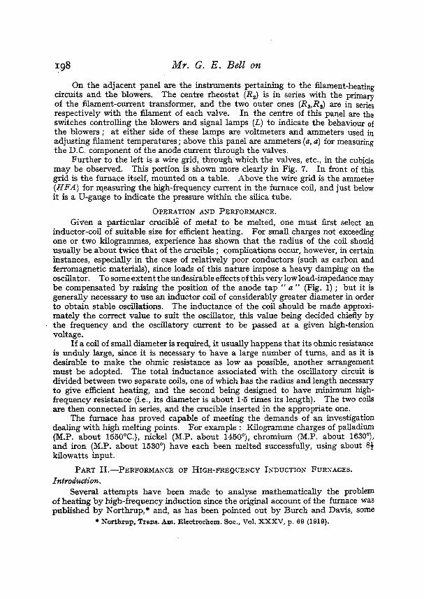
Fig. 8 (reproduced from the paper by Mowe) shows the relation between Rc/Ro It will be seen that if Bz is greater than about 2, R,/R, becomes very nearly
directly proportional to Bz, that is, other things being equal, directly proportional to the square root of the frequency.
The expression Rc= R&/y holds for closely-wound, indefinitely long coils: if the’ turns are slightly separated, the flux density will be reduced. The same result would be brought about by a decrease of permeability from unity to w t l , where tl is the axial thickness of the wire. Further, the effect of the finite length of the coil may be allowed for by taking a further reduced value of the flux density. For a coil whose length is greater than its diameter, this correction does not amount to more than a few per cent.
Thus spaced winding and finite length can be allowed for by taking, instead of Bz, a value
The correction factor l /B1/B may be determined from the
1’/2R, 1 a 0 2 .o 4.0
a d Bz.
o
FIG.~.-CURVE(AFTERHOWE) sE”G RELATION BETWEEN
R.b ~y BE FOR ANY V U U E OF B‘t.
,W’nz,. d B 7 B . following values of HJH given by Howe.
R,IR, AND ,%, FROM WHICH
- (LOC. cit.).
H J H 0.91 0.96 0.98
It is thus possible to determine the behaviour of the furnace under any given con- ditions to an accuracy sufficient for most purposes, when the charge consists of a
solid right circular cylinder of conducting material p 1 a c e d coaxially within the inductor.
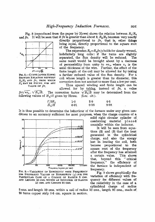
It will be seen from equa- tions (2) and (3) that the heat generated in the cylindrical charge, and also the energy lost in heating the coil, both become proportional to the square root of the frequency after the frequency has attained
t o a certain value. This shows that, beyond this ‘ I critical frequency,” the efficiency of
0 ,000 the furnace is independent of frequency.
100
80
EO
%
& 40 P
Frequency (cycles per sec)
FIG. %-VARIATION OF EFFICIENCY WITH F R E Q W N C Y Fig. 9 shows the FOR DIFFERENT V U T J E S OF RESISTIVITY ( p) FOR THE PARTICTJI,AR CASE OF A CHARGE OF RADIUS 6 CMS. variation Of efficiency with AND LENGTH 10 CMS. WITHIN AN INDUCTOR OF RADIUS quency for different values of
the resistivity in the case of a cylindrical charge of radius
5 cms. andlength 10 cms. within a coil of radius 10 cms., length 20 cms., made af 20 turns copper strip 0.5 cm. square in section.
10 CMS. AND LENGTH 20 CMS.

202 MY. G. E . Bell oh
EXPERIMENTAL RESULTS. An investigation into the behaviour of. induction furnaces was undertaken
with the aid of the valve-maintained furnace described in Part I of this paper. . In this investigation the energy supplied as heat to the charge and that lost
by heating the inductor were separately determined. The inductor consisted of a water-cooled coil 7 cms. radius of 10 turns spaced
1.2 t u n s per centimetre, constructed of copper tubing of circular section & diameter externally.
The inductor fitted closely round a silica tube, and within this was a second non-conducting refractory tube, packed round with asbestos wool, as shown in Fig. 10. The object of this second tube was to permit the specimen under inves- tigation to be inserted and withdrawn without disturbing the lagging.
In making a determination of W, and Wa the specimen was put in the inductor and the high-frequency current maintained at a constant value. Under these
conditions the charge attained a certain steady temperature, at which the heat supplied by the furnace was equal to that lost to the surround- ings. This temperature was measured by means of an optical pyrometer, and subsequently used to determine the energy input to the charge. The energy lost in heating the coil was determined by noting the temperature of the cooling water on entering and leaving the coil and measuring the flow. This was done during the early stages of the experiment, before any appreciable heat reached the coil from the charge by conduction through the lagging. By this means the coil resistance was found to be 0.34 ohm, as a mean of manv observations under different conditions.
After the charge had attained a final steady FIG. l o * - D ~ G ~ OF -A- temperature, the power was switched off and, TIONS THg pERFo-cB after cooling sufficiently, the charge was with-
INDUCTION -ACES. drawn carefully, so as not to disturb the lagging, and wrapped with a heating coil of nichrome wire,
separated from the specimen by the thinnest possible layer of mica for insulation pyposes. The specimen was then carefully replaced within the coil, and a steady drect current passed through the heating coil, so as to raise the specimen to the same h a l temperature as with the induction furnace. It was assumed that the energy necessary to raise the specimen to the steady temperature was approxi- mately the same as that supplied by the furnace. This seem probable, since heating takes place primarily at the surface in each case, and the lagging which determines the heat loss is the same in each case. Actually it was found necessary to ascertain the temperature corresponding to values of the energy supplied by the heating coil, and determine the energy developed in the charge when heated by the induction furnace from the curve representing these observations.
The results of these observations for various specimens at a frequency of 10' cycles per sec. are given in Table I. The energy is given as watts per amp. current in the coil.
ARRAXGED FOR MAKING OBSERVA-

High-Freq.uency Induction Furnaces. 203 TABLE I.
- Nickel cylinder ... Graphite cylinder
...
...
I , I
2.8 Ems. 7.5 cms. 4 x 10⁻⁶ 16.2 x 10⁻⁵ -1 1 8 6 x 10-p
2.6 ., 6.7 ,, 1.6 x 68.6 x 47.4 x 10-0 7.6 X 10⁻¹ 8.0 X lo-' 2.6 ,, 3.8 ,, 4 X 10⁻⁶
4.0 ,, 6.0 ,, , 1 * 5 ~ 1 0 - ~ 106 X10-* 96*0X10-*
Material.
Nickel shot ... ... Chromium pieces ...
Radius Length Energy (of (of 1 Resistivity. observed
crucible). charge). I (watts per amp.). - 2.5 cms. 6 cms. 4 X lo-' 49.0 X lo-' 2.5 ,, 6 ,, j 16X10-' 67.0 X

204 MY. G. E . Bell on
possibility of X-radiation from the apparatus, which is intended for use by non-sp&asts ? The speaker had recently found, in testing a commercial apparatus employing valves of lauge power, that at a particular adjustment the anode voltage rose t o double the high-tension supply. In the present case it was conceivable that X-radiation equivalent in volume to 10 mg. of radium and sufficiently hard to be dangerous, in the absence of protective screening, might be produced.
Dr. R. T. BEATTY noted with interest the author’s conclusion that high frequencies, per- mitting the use of small condensers, are to be preferred in induction furnaces. The paper should have considerable iduence on commercial practice. On what basis had the inductor coil men. tioned in the penultimate paragraph of Part I been designed 1 a prescribed diameter the optimum length of an inductance solenoid is W t e , with a prescribed volume it is zero, and with a prescribed surface it is, according to Butterworth, half the diameter, whereas in the present case the length was two-thirds of the diameter.
Dr. W. H. ECCGES said that the Author had done valuable work in attacking the problem of induction-furnace design from first principles, since high-frequency apparatus has hitherto been designed for wireless purposes, which require high voltages, whereas the present apparatus requires large currents. For instance, the Poulsen arc as designed by wireless engineers might be quite unsuited for the present purpose. What were the relative efhciencies of the Northpp furnace and the present furnace ? Valve apparatus seemed more suitable than high-frequency alternators for such furnaces, since the variation in load produced by the melting of the charge affects the circuit constants of the valve system so as t o cause some degree of self-adjustment. Had the author found a change of frequency corresponding to such a change in load? The conclusion that above 10,000 cycles the frequency is immaterial t o efficiency was an important one.
Dr. H. D. H. DUE (communicated) : The author’s treatment of the essentials of funace design and operation in Part I is very clearly put, and useful from a practical standpoint. I note that the arrangement shown in Fig. 1 was adopted “ owing to limitations of the power supply available.” Since the valves take only a half cycle supply, this arrangement would seem Zikely further to cramp the existing limited power supply. The back to back arrangement would not only evade the objectionable feature of half-cyclic working, but also halve the ampli- tude of the current supply pulses experienced with the arrangement of Fig. 1. It cannot be doubted that with industrial conations of operation, power supply companies would object to the non-cyclic operation which the Author has adopted. A high-frequency furnace which I have had in use satisfactorily for about three years for experimental work upon ceramic materials overcomes these and other dii3iculties. In this two 10 kw. (anode dissipation) silica valves are arranged so that each works upon its appropriate half of the supply current cycle, and the demand upon the public power supply is thus regulatised. The high-frequency side is correspondingly improved, since a sustained wave train is obtained, in place of intermittent wave trains sand- wiched between idle half cycles given by the arrangement of Fig. 1. The Author would seem to sacriiice some efficiency and a measure of satisfactory operation by using the simple expedient of a grid leak and condenser only. For good and foolproof operation a permanent grid potential should be applied, and in the much larger generator to which I have referred above this b arranged by means of a specially designed grid transformer in conjunction with the grid network. With a rectified anode voltage supply this generator would give about 80 kw. output, though as at present arranged its maximum output is 16 kw.
The production of X-radiation from the anodes of valves during operation for furnace work, mentioned by Mr. Gosling, is not a risk to the operator under industrial conditions. With peak voltages of the order 16-20 kv. the X-radiation produced is not very penetrating ; and with either a silica valve or with a water-cooled anode type valve, the X-radiation is emitted, almost exclusively, axially from the anode cylinder. which, with usual valve mountings, means away from the operator.
AUTHOR’S reply : With reference to the remarks of Mr. Gosling and Dr. Drane c o n c w the alternative I ‘ push pull I ’ arrangement, I freely admit that there is every reason t o believe that, in general, this would be more satisfactory from many points of view. The furnace just described, although a permanent addition to the range of furnaces in use in the departmat, is erected in a temporary building, in which the voltage of the available A.C. supply is far below normal ; consequently it is impossible, with the existing apparatus, to obtain the 18,000 t o 20,000 volts necessary for symmetrical working. The voltage could, of course, be raised initially by Using a low-ratio step-up transformer ; but as the furnace fu16ls its immediate requirements, this step is not necessary at the moment. The modilkations necessary for symmetrical working
It had been shown that

High-Freqzcency Induction Furnaces. 205
=e very slight, and the v a l ~ ~ e s of the various capacities, inductances, etc., would probably not be appreciably altered.
NO experiments have been made with regard t o the production'of X-rays from the valva, but tests will be made at the next opportunity. The only protection from X-rays is about 7 ft.. of &, which is much more than the minimum given by the makers of the valves. As a result of the discussion f o ~ o w h g a series of Papers on various kinds of valves read before the 1.E.B (see Inst. El. Eng. J., 65. pp. 812-822, 1927), it was considered that there was not likely t o be anp danger from this source. The experience of Mr. Gosling shows very clearly that no appa- ratus should be considered as safe until it has actually been proved t o be safe by suitable measurements.
With regard to the question about coils asked by Dr. Beatty, the problem arises when it is required t o heat a very small crucible of metal-say, three quarters of an inch in diameter a d two inches long. The coil must fit fairly closely round the crucible, and hence must have a diameter of only about one or one and a half inches ; further, its inductancemust be of the order of 12 microhenries. To obtain this inductance in a single layer coil a large number of turns is required, and the coil is unwieldy, as well as having an unnecessarily high ohmic resistance. Consequently, it is advantageous to make a coil of convenient shape and reasonably low ohmic resistance t o give the required inductance, and t o put this in series with the small coil of only a very few turns which serves t o heat the metal. To meet the case of heating a small charge, Northrup devised what he calls the " focus inductor," which is described in his Paper i the Trans. Am. Electro-Chem. Soc. already mentioned. Efforts t o utilise this in the valve- maintained furnace have not been successful.
Although no definite information is available, there is reason t o believe that the efficiencies of the valve furnace and the Northrup furnace are comparable.
The interesting point regarding the change of frequency on melting also raised by the Presi- dent wiU be investigated aa soon as possible ; but I think that little change will be found when the charge consists of a solid cylindrical ingot. It is a suprising fact that there is, in general, no appreciable change in the operating constants (output current, etc.) in these circumstances. On melting, the shape of the ingot does not alter, and hence it would appear that there can be no abrupt change of resistivity on pasing from the solid t o the liquid state.
On melting a crucible full of pieces of metal a very de6nite increase of oscillatory curtent occurs on melting, and presumably there is a correspondingly great change of frequency.