Embed Size (px)
Citation preview

Volume 2 • Issue 3 • 1000113J Aeronaut Aerospace EngISSN: 2168-9792 JAAE, an open access journal
Open AccessTechnical Note
Isaac and Graham, J Aeronaut Aerospace Eng 2013, 2:3 DOI: 10.4172/2168-9792.1000113
When we think of CFD (computational fluid dynamics) in the aerospace and aeronautical industries, we often limit our thinking to the aerodynamic analysis of wing/tail structure or fuselages. But CFD analysis applies to almost all of the critical components and systems of an aircraft. For example, excessive heat in the electronic components can lead to failure and reliability issues. Fuel delivery and engine cooling systems must be optimized. Cabin air conditioning/heating systems need to be analyzed. And the industry cannot afford to either over-conservatively design these systems (excessive cost) or prove efficiency/reliability by building multiple physical prototypes, testing in labs, and then re-designing, which is a long and expensive process. Because of these issues, CFD comes into play early and throughout the design process for multiple components and systems in the aircraft.
Using CFD is no longer relegated to the realm of the specialist. A new class of CFD analysis software, “Concurrent CFD,” is proving to be highly effective at performing these analyses, enabling design engineers as well as specialists to accelerate key decisions at their workstations as they experiment with design scenarios and as they hone in on the best, most efficient, reliable, and cost-effective design. With CFD embedded into the MCAD environment, this intuitive process allows design engineers to optimize a product during the design stages; and that first physical prototype will often be the design that goes into final manufacturing.
Until recently, the commercial software available for CFD typically has been geared toward only the specialists, limiting its widespread use. Besides being expensive, these tools have been challenging to use. As a result, engineering analysis for applications such as pressure drop, heat transfer, fluid flow, etc. traditionally have been carried out only by CFD specialists in analysis departments, separate from mainstream design and development departments. This limited the number of design approaches tested and taxed the overburdened specialists.
Fortunately, new tools have emerged that embed a complete range of flow analyses within mainstream MCAD toolsets such as CATIA® V5, PTC Creo®, and Siemens NXTM. For example, the FloEFDTM design/analysis technology offered by Mentor Graphics is specifically targeted at the design engineer as well as the specialist. It has the combination of simulation accuracy plus the ease-of-use and speed needed to be used as an integral part of the design process.
With these new CFD tools, a design engineer with standard training and working in any size company can use his or her existing knowledge to successfully perform analyses, all within the familiar MCAD environment of choice. Certainly, there will always be a few very demanding applications where more advanced CFD knowledge is needed to fine-tune the meshing and solver settings to converge to a solution. However, taking CFD out of the exclusive domain of specialists and bringing it into the mainstream enables design engineers with little specific training in CFD to analyze problems in roughly 80 to 90% of the time compared to using traditional tools. This offers designers a fundamental breakthrough in design efficiency.
Characteristics of CFD Targeted at the Design EngineerFor example, some CFD simulation software provides a complete
environment for performing analysis such as heat transfer by combining all the phases of analysis in one single package: from solid modeling, to problem set up, running, results visualization, validating the design, and reporting. Figure 1 illustrates some of the important characteristics of CFD software that enables it to be useful to design engineers and not just specialists.
MCAD system embedded
All the designer needs is knowledge of the MCAD system and the physics of the product to use next-generation CFD. After installation, all the menus and commands necessary to run a full CFD flow analysis are created in the MCAD package’s menu system. This CFD embedded within the MCAD system makes it extremely easy to use. The design engineer is already familiar with the menu structures. The CFD analysis tool uses the same GUI structures so the engineer does not have to learn a completely new interface (Figure 2).
The starting point of any heat transfer and fluid flow analysis is to define the overall boundary conditions of the problem. A wizard is available to direct the setup, including the selection of models. This lets a designer take advantage of existing MCAD models for analysis, without having to export or import additional data, saving significant amount of time and effort. The embedded CFD software can use newly
*Corresponding author: Suzanne Graham, Senior Public Relations Manager,Mechanical Analysis Division, Mentor Graphics Corporation, Wilsonville Oregon,USA, Tel: 503-685-7789; 503 789-2766; E-mail: [email protected]
Received May 24, 2013; Accepted June 26, 2013; Published July 04, 2013
Citation: Isaac J, Graham S (2013) CFD in the Aerospace and AeronauticsIndustries. J Aeronaut Aerospace Eng 2: 113 doi:10.4172/2168-9792.1000113
Copyright: © 2013 Isaac J, et al. This is an open-access article distributed underthe terms of the Creative Commons Attribution License, which permits unrestricted use, distribution, and reproduction in any medium, provided the original author and source are credited.
CFD in the Aerospace and Aeronautics IndustriesJohn Isaac and Suzanne Graham*Mechanical Analysis Division, Mentor Graphics Corporation, Wilsonville Oregon, USA
Intuitive Easy-to-use
Interfaces forEngineers
CAD-Embedded withinPLM Packages
NX SIE MENS
Fast AutomatedImmersedBoundaryCartesianMeshing
UniqueTransitionalTurbulence
model
...leads to Concurrent CFD
Multi-variant
Parametric’’What if”Analysis
AutomatedSolution
ConvergenceBuilt-in
Unique Modified 2Layer Wall Function
for BoundaryLayers
Figure 1: Enabling design engineers as well as specialists to perform CFD analysis requires technologies that automate difficult processes like meshing, integration with the MCAD system, guidance through the setup with wizards, etc.
Journal of Aeronautics & Aerospace EngineeringJo
urna
l of A
eron
autics & Aerospace Engineering
ISSN: 2168-9792

Citation: Isaac J, Graham S (2013) CFD in the Aerospace and Aeronautics Industries. J Aeronaut Aerospace Eng 2: 113 doi:10.4172/2168-9792.1000113
Page 2 of 4
Volume 2 • Issue 3 • 1000113J Aeronaut Aerospace EngISSN: 2168-9792 JAAE, an open access journal
created or existing 3D CAD geometry and solid model information to simulate designs in real-world conditions.
Automated cartesian meshing
Once a model is created, the model needs to be meshed. Developing a mesh is one of those skills that previously separated CFD specialists from mechanical design engineers. With FloEFD, meshes are created automatically in a matter of minutes rather than requiring hours of tedious proportioning of regions and cells. The software actually creates an adaptive mesh that reduces the cell size (increasing the resolution of the analysis) to ensure more accurate simulation results in complex areas of the model, as shown in Figure 3.
Easy-to-Use engineer oriented interfaces
Stepping through the analysis process can be very confusing to the non-specialist. However, with a next-generation CFD tool, the design engineer is stepped through the process by wizards that ensure all data such as materials, fluid characteristics, boundary conditions, and execution parameters are properly defined.
Multi-Variant parametric modeling
This feature enables the design engineer to set up a series of experiments and submit multiple analyses for batch runs. The engineer can define a range of values and then modify the design (number of fins on the heat sink, dimensions of an outlet, etc.) or boundary conditions (pressure, flow volume, temperature, etc.) across a spectrum. The software automatically generates a series of analysis runs and submits them for execution. The results of these experiments can be compared and visualized, and then the best design can be chosen.
Laminar-Turbulent transitional modeling
The modeling of a fluid flow is extremely complex while the flow transitions from laminar to turbulent or vice versa. In typical CFD software, this requires two different models and an understanding on the part of the engineer as to which one should be used. A model that senses this transition and automatically employs the correct modeling at the correct time in the transition eliminates the need for two different models and the intervention of the engineer (Figure 4).
Automated/Guaranteed convergence
One of the most difficult tasks even for the CFD specialist is to ensure that the CFD analysis converges. Many factors can contribute to a CFD analysis non-convergence. Model complexity, meshing, boundary conditions, etc. can all cause older-generation software not to converge. The specialist must then experiment, sometimes using trial and error, to urge the software into convergence. With software such as FloEFD, convergence is virtually guaranteed, thus eliminating the need for the design engineer to tweak the model.
These are just some examples of the technologies that enable complex CFD to be put into the hands of the design engineer as well as the specialist.
CFD Analysis from Complex Components to SystemsWhen we think of CFD analysis, we might limit our thinking to the
individual components of an aircraft or satellite, such as the electronics in a navigation computer for proper heat management, the fuel flow through an injector, or the capability of an oil cooling component. We might not imagine, given the size and complexity of a complete system such as fuel delivery, that we could analyze it with all the feet of piping, pumps, valves, etc. in an efficient manner. Using a traditional 3D CFD tool for this type of analysis would create a huge model requiring excessive computing power to analyze.
On the other hand, if we limited our analysis to the straight one-dimensional (1D) flow of the fuel through the piping, we would compromise accuracy by not considering the effects of the complex components in the system. A good solution is to analyze the many feet of piping using a 1D CFD analysis software, such as the Mentor GraphicFlowmaster1D flow simulation software, while inserting the models for the more complex components using 3D CFD analysis. Figure 5 shows an example of this type of system: an air-to-air refueling
Figure 2: This example shows the FloEFD analysis software as embedded into the CATIAV5 MCAD system—same look/feel and GUI.
Figure 3: Using a rectangular adaptive mesh, FloEFD can automatically adjust cell size to deliver better resolution anywhere it is needed.
10 2
10 1
10 0
10-1
10 - 1 100 101 102 103 104 105 106 107
Experiment
FloEFD Technology
CD=
PV2
Fd
D
Figure 4: A nalysis and experimental results are closely correlated using the laminar/turbulent transitional modeling.
Citation: Isaac J, Graham S (2013) CFD in the Aerospace and Aeronautics Industries. J Aeronaut Aerospace Eng 2: 113 doi:10.4172/2168-9792.1000113
Page 3 of 4
Volume 2 • Issue 3 • 1000113J Aeronaut Aerospace EngISSN: 2168-9792 JAAE, an open access journal
system with pipes and the refueling nozzle and how the combination of the 1D-3D analysis works.
The output from such an analysis could be a determination of the flow rates to refuel the jet or the “water hammer” effects if the aircraft were to suddenly disengage (Figure 6).
Example of Using CFD—Bell Helicopter Improves Safety, Saves Cost on Fuel Tank DesignRequirements
Bell Helicopter manufactures helicopters designed for a broad range of commercial and military applications. The latter class of aircraft includes defensive features designed to protect the helicopter and its occupants in the most adverse situations. Bell Helicopter needed a cost-effective evaluation solution that would give reliable results and guide the design of these and other complex features.
Bell engineers were tasked with reviewing and refining a system that
injects nitrogen gas into the helicopter’s fuel tank to displace oxygen as the fuel is consumed. This makes the tank less likely to ignite if it is hit by an incendiary projectile. The incoming nitrogen must fill the tank’s recesses rapidly since, after all, the assumption is that the helicopter is under hostile fire and needs to escape as quickly as possible.
How long must the pilot wait before taking off from the “hot” landing zone? When can he or she be confident that air in the fuel tank won’t jeopardize the aircraft’s safety? It is a question of time, and seconds matter.
Historically, the question has been answered by running physical tests with actual hardware components—pumps, valves, and the tank itself. This method of testing is very expensive and time-consuming. And in Bell’s case the costs are multiplied because the venting system is built by a subcontractor in Europe, and personnel from the other companies involved must travel to the test site with expensive equipment to set up and run the test.
Solution
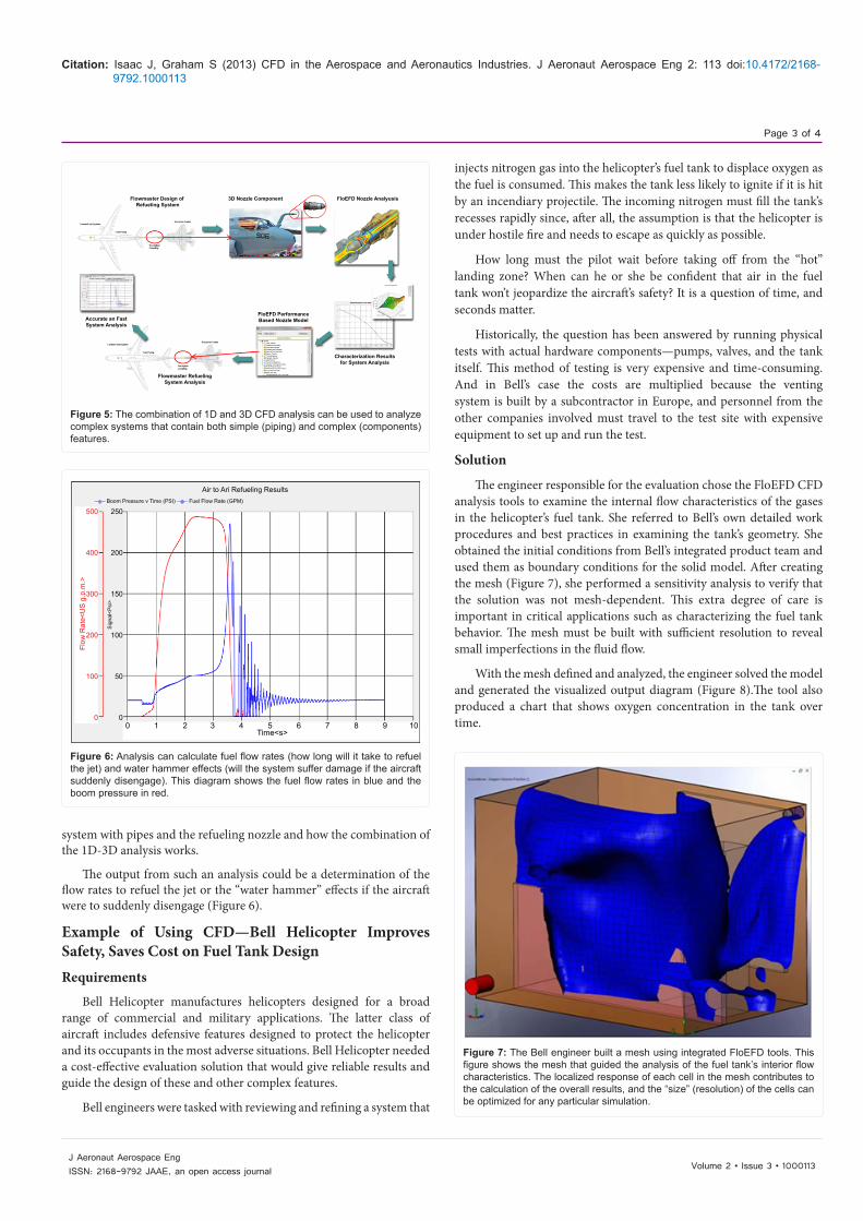
The engineer responsible for the evaluation chose the FloEFD CFD analysis tools to examine the internal flow characteristics of the gases in the helicopter’s fuel tank. She referred to Bell’s own detailed work procedures and best practices in examining the tank’s geometry. She obtained the initial conditions from Bell’s integrated product team and used them as boundary conditions for the solid model. After creating the mesh (Figure 7), she performed a sensitivity analysis to verify that the solution was not mesh-dependent. This extra degree of care is important in critical applications such as characterizing the fuel tank behavior. The mesh must be built with sufficient resolution to reveal small imperfections in the fluid flow.
With the mesh defined and analyzed, the engineer solved the model and generated the visualized output diagram (Figure 8).The tool also produced a chart that shows oxygen concentration in the tank over time.
Flowmaster Design of Refueling System
Accurate an FastSystem Analysis
FloEFD PerformanceBased Nozzle Model
Flowmaster RefuelingSystem Analysis
Characterization Resuitsfor System Analysis
3D Nozzle Component FloEFD Nozzle Analyusis
Figure 5: The combination of 1D and 3D CFD analysis can be used to analyze complex systems that contain both simple (piping) and complex (components) features.
0 1 2 3 4 5 6 7 8 9 10Time<s>
250
200
150
100
50
0
Boom Pressure v Time (PSI) Fuel Flow Rate (GPM)
500
400
300
200
100
0
Flow
Rat
e<U
S g
.p.m
.>
Air to Ari Refueling Results
Sig
nal<
Psi
>
Figure 6: Analysis can calculate fuel flow rates (how long will it take to refuel the jet) and water hammer effects (will the system suffer damage if the aircraft suddenly disengage). This diagram shows the fuel flow rates in blue and the boom pressure in red.
Figure 7: The Bell engineer built a mesh using integrated FloEFD tools. This figure shows the mesh that guided the analysis of the fuel tank’s interior flow characteristics. The localized response of each cell in the mesh contributes to the calculation of the overall results, and the “size” (resolution) of the cells can be optimized for any particular simulation.

Citation: Isaac J, Graham S (2013) CFD in the Aerospace and Aeronautics Industries. J Aeronaut Aerospace Eng 2: 113 doi:10.4172/2168-9792.1000113
Page 4 of 4
Volume 2 • Issue 3 • 1000113J Aeronaut Aerospace EngISSN: 2168-9792 JAAE, an open access journal
Results
The iso surfaces of oxygen concentration resulting from the simulation revealed that several areas in the tank were not being adequately vented. Consequently, a potential problem was identified
and solved at very low cost compared to physical testing. Among the design changes included were adding a second redistribution nozzle. Had this issue remained undetected until the prototype phase, it would have been far more expensive to correct the problem and moreover, might have delayed the project.
Here, CFD analysis made it possible for a staff-level engineer to evaluate and correct a suspected problem without the intervention of a specialized fluid dynamics analyst.
SummaryAerospace companies are under pressure to create the best
performing products and to design those products on schedule.CFD analysis plays an important role in the design process by reducing the need for multiple time- and cost-consuming physical prototypes that must be manufactured and tested, problems discovered, and re-designed if necessary. Prototypes will always play an important role in the development process but reducing the time and money expended on them can help a company meet its business goals.
It is also apparent that putting CFD in the hands of the design engineer as well as the CFD specialist opens the door to additional and efficient experimentation with design approaches. This can result in a much more optimized product and reduce the need to over-conservatively engineer. Modern CFD software now has technologies that enable mechanical engineers to use CFD as an integral part of their design process.
Figure 8: This figure shows a visualization of the flow of gases within the helicopter fuel tank produced by FloEFD. The study revealed several areas that were not adequately vented.